Embed Size (px)
Citation preview
OPERATION AND MAINTENANCE MANUAL FOR
JO-NA’s WASTEWATER TREATMENT PLANT
Prepared by: Voltaire L. Acosta
1. WASTEWATER TREATMENT FACILITY
JO-NA’s International Philippines, Inc. is a
manufacturing firm that is engaged primarily on the
production of noodles, snack foods, and preserved
products such as nata de coco (coco gel) and kaong, with
markets in the U.S., Japan, and Europe.
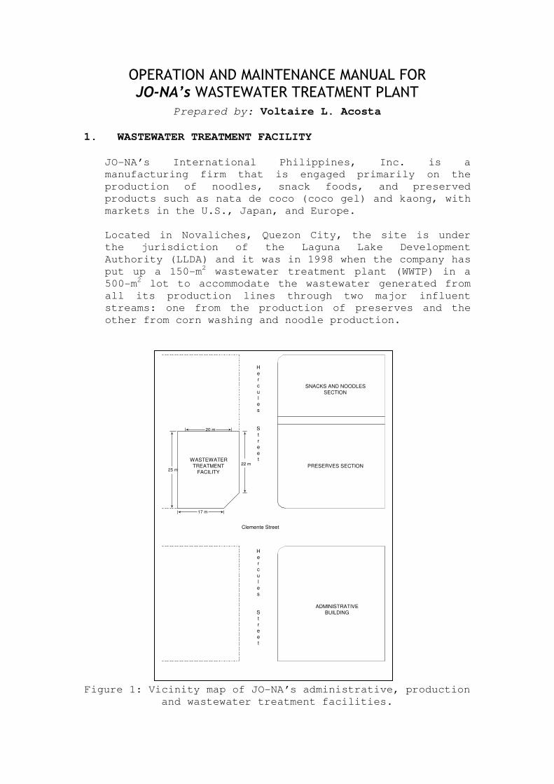
Located in Novaliches, Quezon City, the site is under
the jurisdiction of the Laguna Lake Development
Authority (LLDA) and it was in 1998 when the company has
put up a 150-m2 wastewater treatment plant (WWTP) in a
500-m2 lot to accommodate the wastewater generated from
all its production lines through two major influent
streams: one from the production of preserves and the
other from corn washing and noodle production.
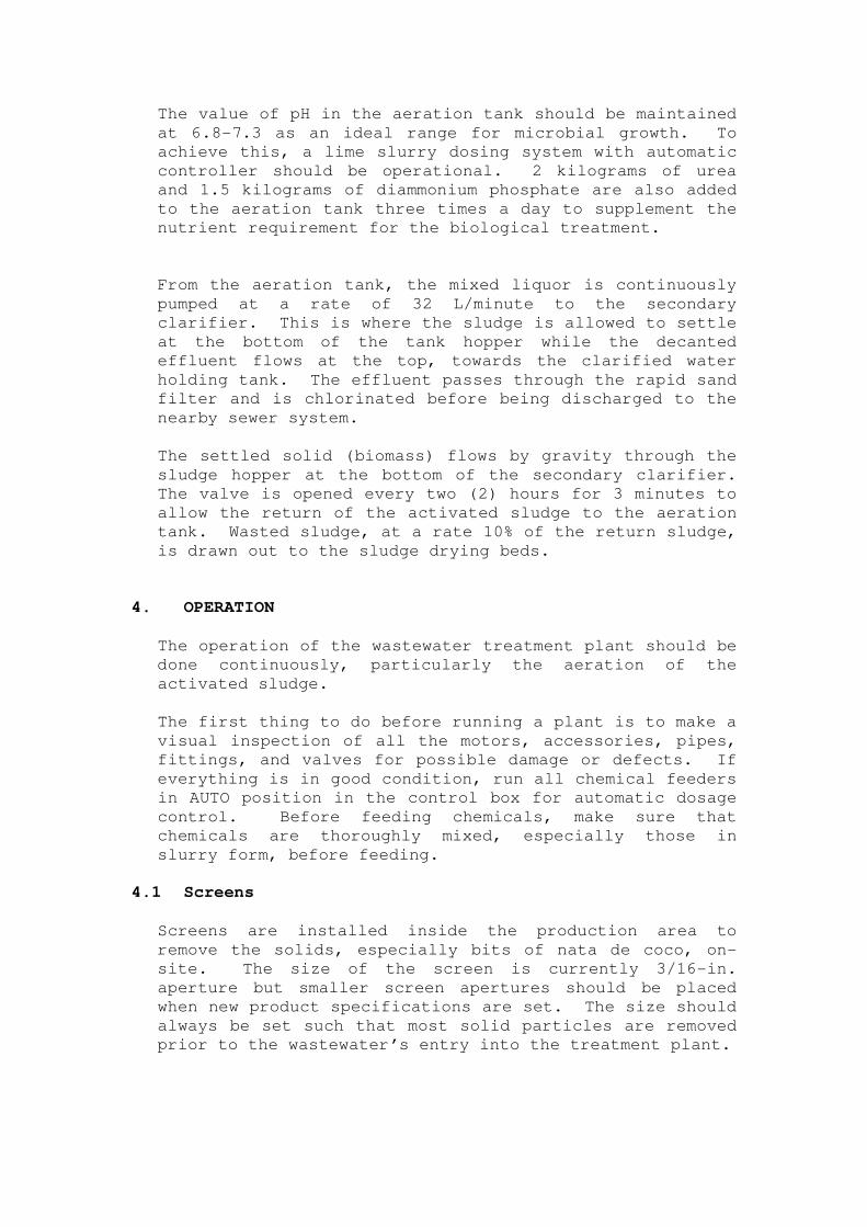
Figure 1: Vicinity map of JO-NA’s administrative, production
and wastewater treatment facilities.
WASTEWATER
TREATMENTFACILITY
SNACKS AND NOODLES
SECTION
PRESERVES SECTION
ADMINISTRATIVE
BUILDING
25 m
17 m
20 m
22 m
He
r
c
u
le
s
S
t
r
e
et
Clemente Street
H
e
rc
u
l
e
s
S
tr
e
e
t
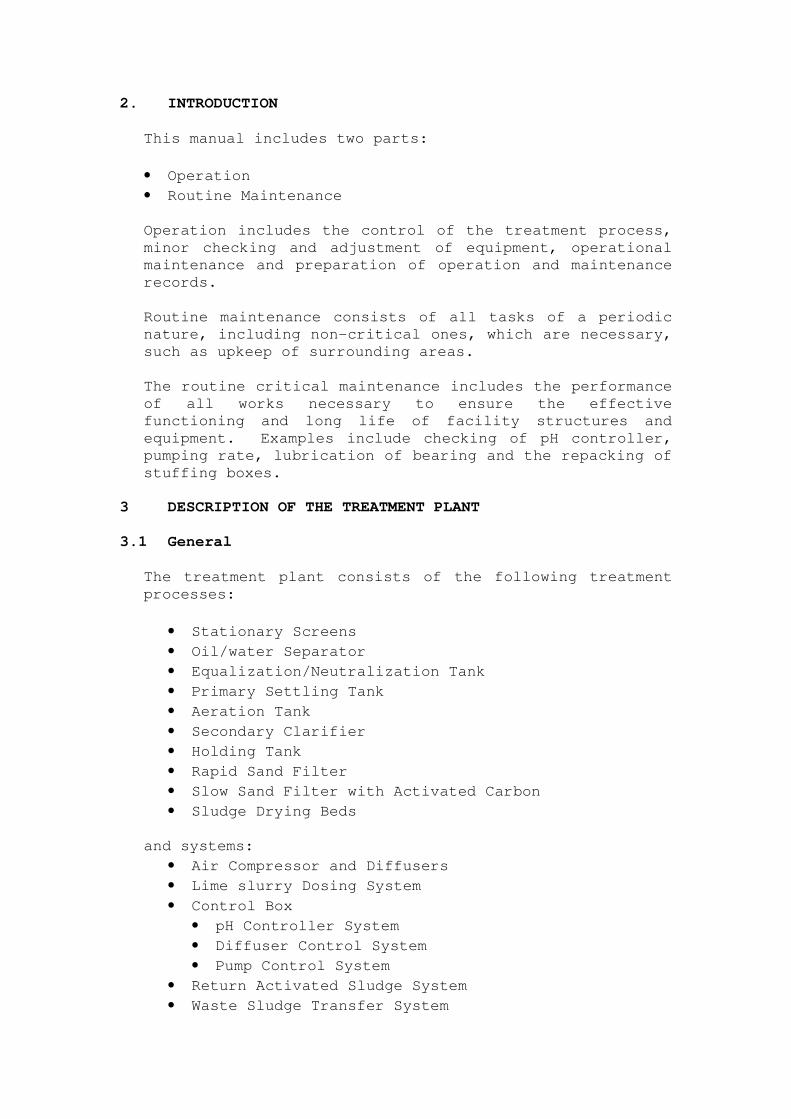
2. INTRODUCTION
This manual includes two parts:
• Operation
• Routine Maintenance
Operation includes the control of the treatment process,
minor checking and adjustment of equipment, operational
maintenance and preparation of operation and maintenance
records.
Routine maintenance consists of all tasks of a periodic
nature, including non-critical ones, which are necessary,
such as upkeep of surrounding areas.
The routine critical maintenance includes the performance
of all works necessary to ensure the effective
functioning and long life of facility structures and
equipment. Examples include checking of pH controller,
pumping rate, lubrication of bearing and the repacking of
stuffing boxes.
3 DESCRIPTION OF THE TREATMENT PLANT
3.1 General
The treatment plant consists of the following treatment
processes:
• Stationary Screens
• Oil/water Separator
• Equalization/Neutralization Tank
• Primary Settling Tank
• Aeration Tank
• Secondary Clarifier
• Holding Tank
• Rapid Sand Filter
• Slow Sand Filter with Activated Carbon
• Sludge Drying Beds
and systems:
• Air Compressor and Diffusers
• Lime slurry Dosing System
• Control Box
• pH Controller System
• Diffuser Control System
• Pump Control System
• Return Activated Sludge System
• Waste Sludge Transfer System
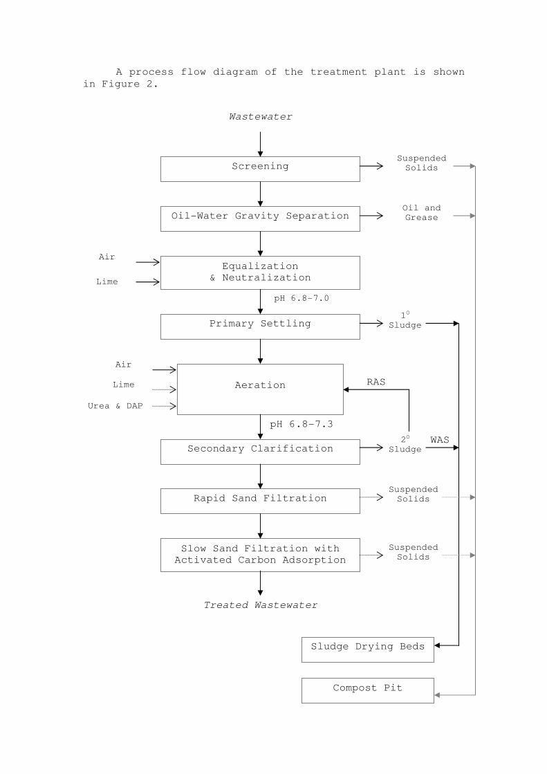
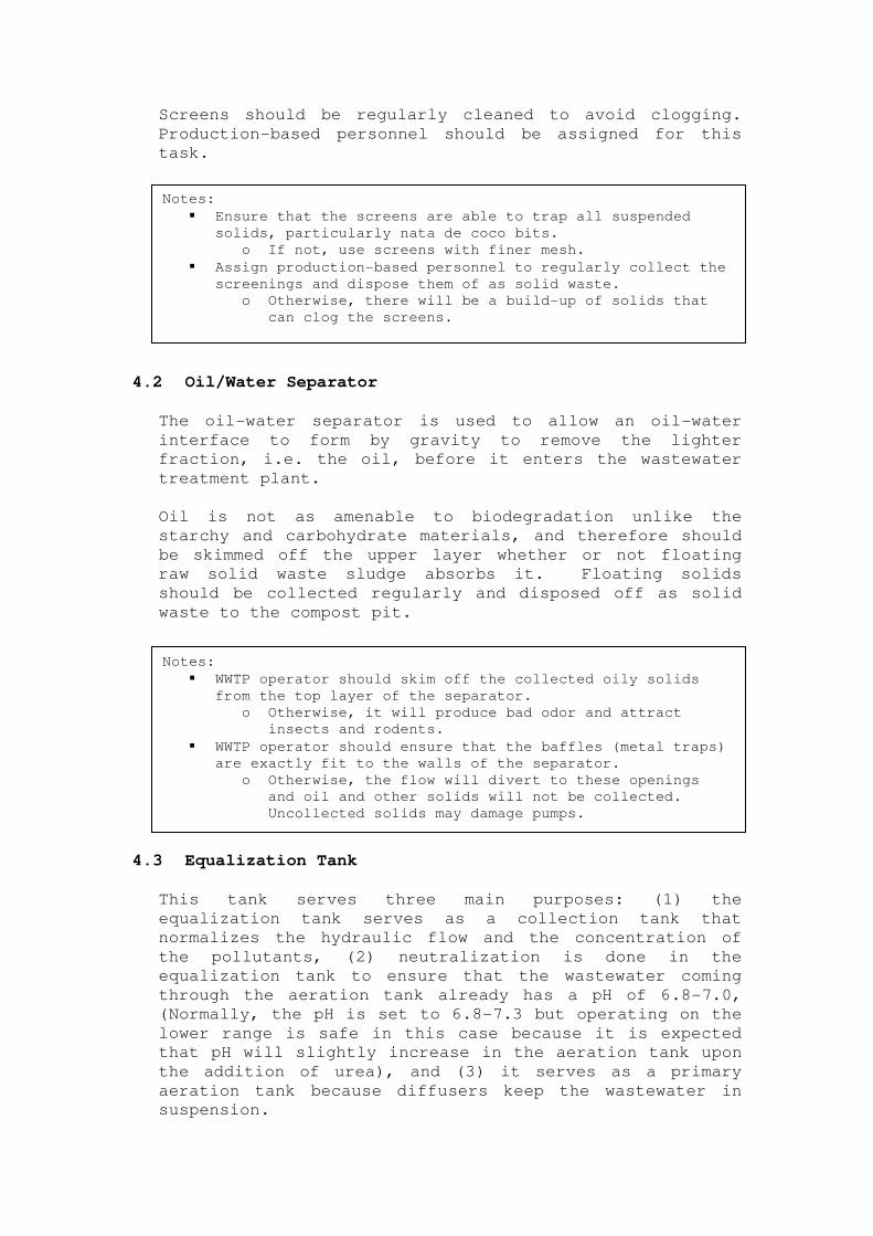
A process flow diagram of the treatment plant is shown
in Figure 2.
Screening
Oil-Water Gravity Separation
Equalization
& Neutralization
Primary Settling
Aeration
Secondary Clarification
Rapid Sand Filtration
Slow Sand Filtration with
Activated Carbon Adsorption
Wastewater
Suspended Solids
Oil and Grease
Air
Lime
pH 6.8-7.0
1O
Sludge
pH 6.8-7.3
Air
Lime
Urea & DAP
2O
Sludge
Suspended Solids
Suspended Solids
Sludge Drying Beds
Compost Pit
RAS
WAS
Treated Wastewater
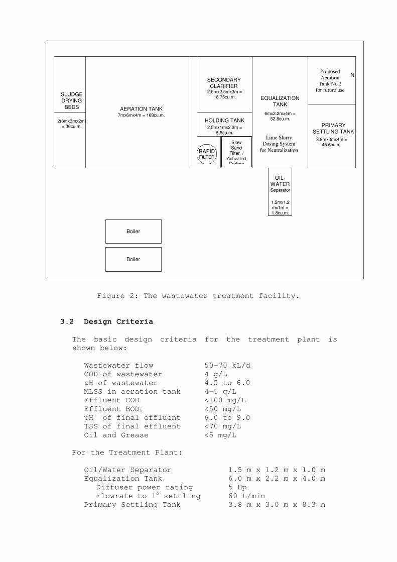
Figure 2: The wastewater treatment facility.
3.2 Design Criteria
The basic design criteria for the treatment plant is
shown below:
Wastewater flow 50-70 kL/d
COD of wastewater 4 g/L
pH of wastewater 4.5 to 6.0
MLSS in aeration tank 4-5 g/L
Effluent COD <100 mg/L
Effluent BOD5 <50 mg/L
pH of final effluent 6.0 to 9.0
TSS of final effluent <70 mg/L
Oil and Grease <5 mg/L
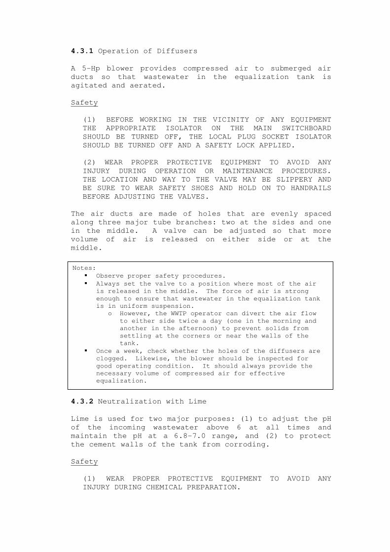
For the Treatment Plant:
Oil/Water Separator 1.5 m x 1.2 m x 1.0 m
Equalization Tank 6.0 m x 2.2 m x 4.0 m
Diffuser power rating 5 Hp
Flowrate to 1o settling 60 L/min
Primary Settling Tank 3.8 m x 3.0 m x 8.3 m
RAPIDFILTER
OIL-WATERSeparator
Boiler
Boiler
NEUTRALIZATION
TANK
PRIMARYSETTLING TANK
EQUALIZATIONTANK
SECONDARYCLARIFIER
HOLDING TANK
CHLORI-NATION
TANK
AERATION TANK
SLUDGEDRYING
BEDS
2(3mx3mx2m)= 36cu.m.
1.5mx1.2mx1m =1.8cu.m.
7mx6mx4m = 168cu.m. 6mx2.2mx4m =52.8cu.m.
2.5mx2.5mx3m =18.75cu.m.
2.5mx1mx2.2m =
5.5cu.m.
1mx1mx2m =2cu.m.
3.8mx3mx4m =45.6cu.m.
3.8mx3mx4m =45.6cu.m.
Proposed
Aeration
Tank No.2
for future use
Lime Slurry
Dosing System
for Neutralization
Slow Sand
Filter / ActivatedCarbon
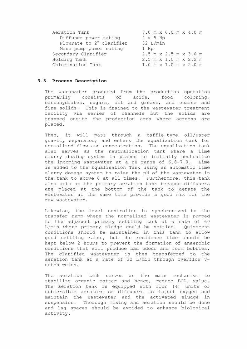
Aeration Tank 7.0 m x 6.0 m x 4.0 m
Diffuser power rating 4 x 5 Hp
Flowrate to 2o clarifier 32 L/min
Mono pump power rating 1 Hp
Secondary Clarifier 2.5 m x 2.5 m x 3.6 m
Holding Tank 2.5 m x 1.0 m x 2.2 m
Chlorination Tank 1.0 m x 1.0 m x 2.0 m
3.3 Process Description
The wastewater produced from the production operation
primarily consists of acids, food coloring,
carbohydrates, sugars, oil and grease, and coarse and
fine solids. This is drained to the wastewater treatment
facility via series of channels but the solids are
trapped onsite the production area where screens are
placed.
Then, it will pass through a baffle-type oil/water
gravity separator, and enters the equalization tank for
normalized flow and concentration. The equalization tank
also serves as the neutralization tank where a lime
slurry dosing system is placed to initially neutralize
the incoming wastewater at a pH range of 6.8-7.0. Lime
is added to the Equalisation Tank using an automatic lime
slurry dosage system to raise the pH of the wastewater in
the tank to above 6 at all times. Furthermore, this tank
also acts as the primary aeration tank because diffusers
are placed at the bottom of the tank to aerate the
wastewater at the same time provide a good mix for the
raw wastewater.
Likewise, the level controller is synchronized to the
transfer pump where the normalized wastewater is pumped
to the adjacent primary settling tank at a rate of 60
L/min where primary sludge could be settled. Quiescent
conditions should be maintained in this tank to allow
good settling rates, but the residence time should be
kept below 2 hours to prevent the formation of anaerobic
conditions that will produce bad odour and form bubbles.
The clarified wastewater is then transferred to the
aeration tank at a rate of 32 L/min through overflow v-
notch weirs.
The aeration tank serves as the main mechanism to
stabilize organic matter and hence, reduce BOD5 value.
The aeration tank is equipped with four (4) units of
submersible aerators or diffusers to inject oxygen and
maintain the wastewater and the activated sludge in
suspension. Thorough mixing and aeration should be done
and lag spaces should be avoided to enhance biological
activity.
The value of pH in the aeration tank should be maintained
at 6.8-7.3 as an ideal range for microbial growth. To
achieve this, a lime slurry dosing system with automatic
controller should be operational. 2 kilograms of urea
and 1.5 kilograms of diammonium phosphate are also added
to the aeration tank three times a day to supplement the
nutrient requirement for the biological treatment.
From the aeration tank, the mixed liquor is continuously
pumped at a rate of 32 L/minute to the secondary
clarifier. This is where the sludge is allowed to settle
at the bottom of the tank hopper while the decanted
effluent flows at the top, towards the clarified water
holding tank. The effluent passes through the rapid sand
filter and is chlorinated before being discharged to the
nearby sewer system.
The settled solid (biomass) flows by gravity through the
sludge hopper at the bottom of the secondary clarifier.
The valve is opened every two (2) hours for 3 minutes to
allow the return of the activated sludge to the aeration
tank. Wasted sludge, at a rate 10% of the return sludge,
is drawn out to the sludge drying beds.
4. OPERATION
The operation of the wastewater treatment plant should be
done continuously, particularly the aeration of the
activated sludge.
The first thing to do before running a plant is to make a
visual inspection of all the motors, accessories, pipes,
fittings, and valves for possible damage or defects. If
everything is in good condition, run all chemical feeders
in AUTO position in the control box for automatic dosage
control. Before feeding chemicals, make sure that
chemicals are thoroughly mixed, especially those in
slurry form, before feeding.
4.1 Screens
Screens are installed inside the production area to
remove the solids, especially bits of nata de coco, on-
site. The size of the screen is currently 3/16-in.
aperture but smaller screen apertures should be placed
when new product specifications are set. The size should
always be set such that most solid particles are removed
prior to the wastewater’s entry into the treatment plant.
Screens should be regularly cleaned to avoid clogging.
Production-based personnel should be assigned for this
task.
4.2 Oil/Water Separator
The oil-water separator is used to allow an oil-water
interface to form by gravity to remove the lighter
fraction, i.e. the oil, before it enters the wastewater
treatment plant.
Oil is not as amenable to biodegradation unlike the
starchy and carbohydrate materials, and therefore should
be skimmed off the upper layer whether or not floating
raw solid waste sludge absorbs it. Floating solids
should be collected regularly and disposed off as solid
waste to the compost pit.
4.3 Equalization Tank
This tank serves three main purposes: (1) the
equalization tank serves as a collection tank that
normalizes the hydraulic flow and the concentration of
the pollutants, (2) neutralization is done in the
equalization tank to ensure that the wastewater coming
through the aeration tank already has a pH of 6.8-7.0,
(Normally, the pH is set to 6.8-7.3 but operating on the
lower range is safe in this case because it is expected
that pH will slightly increase in the aeration tank upon
the addition of urea), and (3) it serves as a primary
aeration tank because diffusers keep the wastewater in
suspension.
Notes:
� Ensure that the screens are able to trap all suspended
solids, particularly nata de coco bits.
o If not, use screens with finer mesh.
� Assign production-based personnel to regularly collect the
screenings and dispose them of as solid waste.
o Otherwise, there will be a build-up of solids that
can clog the screens.
Notes:
� WWTP operator should skim off the collected oily solids
from the top layer of the separator.
o Otherwise, it will produce bad odor and attract
insects and rodents.
� WWTP operator should ensure that the baffles (metal traps)
are exactly fit to the walls of the separator.
o Otherwise, the flow will divert to these openings
and oil and other solids will not be collected.
Uncollected solids may damage pumps.
4.3.1 Operation of Diffusers
A 5-Hp blower provides compressed air to submerged air
ducts so that wastewater in the equalization tank is
agitated and aerated.
Safety
(1) BEFORE WORKING IN THE VICINITY OF ANY EQUIPMENT
THE APPROPRIATE ISOLATOR ON THE MAIN SWITCHBOARD
SHOULD BE TURNED OFF, THE LOCAL PLUG SOCKET ISOLATOR
SHOULD BE TURNED OFF AND A SAFETY LOCK APPLIED.
(2) WEAR PROPER PROTECTIVE EQUIPMENT TO AVOID ANY
INJURY DURING OPERATION OR MAINTENANCE PROCEDURES.
THE LOCATION AND WAY TO THE VALVE MAY BE SLIPPERY AND
BE SURE TO WEAR SAFETY SHOES AND HOLD ON TO HANDRAILS
BEFORE ADJUSTING THE VALVES.
The air ducts are made of holes that are evenly spaced
along three major tube branches: two at the sides and one
in the middle. A valve can be adjusted so that more
volume of air is released on either side or at the
middle.
4.3.2 Neutralization with Lime
Lime is used for two major purposes: (1) to adjust the pH
of the incoming wastewater above 6 at all times and
maintain the pH at a 6.8-7.0 range, and (2) to protect
the cement walls of the tank from corroding.
Safety
(1) WEAR PROPER PROTECTIVE EQUIPMENT TO AVOID ANY
INJURY DURING CHEMICAL PREPARATION.
Notes:
� Observe proper safety procedures.
� Always set the valve to a position where most of the air
is released in the middle. The force of air is strong
enough to ensure that wastewater in the equalization tank
is in uniform suspension.
o However, the WWTP operator can divert the air flow
to either side twice a day (one in the morning and
another in the afternoon) to prevent solids from
settling at the corners or near the walls of the
tank.
� Once a week, check whether the holes of the diffusers are
clogged. Likewise, the blower should be inspected for
good operating condition. It should always provide the
necessary volume of compressed air for effective
equalization.
(2) OBSERVE PROPER PRECAUTIONARY MEASURES IN HANDLING
CHEMICALS. ALWAYS POUR IN CHEMICALS IN WATER AND NOT
THE OTHER WAY AROUND!
For the automatic dosage, prepare 20 kgs. of lime and mix
with 100 liters of tap water (If an 8-liter pail is used,
add 1.5 kgs of lime and then fill the container with
water). Mix them slowly while adding to completely
dissolve the chemicals in water before feeding. Then
pour the slurry into the lime slurry-dosing tank.
Switch the slurry dosing control system connected to the
pH control system to automatically dose the required lime
to achieve the pH range of 6.8-7.0. Pour in another
batch of lime slurry when the slurry level is almost ¼ of
the container.
Lime is not completely soluble in water and settles under
quiescent conditions inside the slurry tank. Instead of
a paddle mixer, a small air tube, which is connected to
the diffuser line, is used to agitate the chemical
mixture.
4.3.3 Pumping into Primary Settling Tank
Wastewater coming from the equalization tank should be
transferred to the primary settling tank to remove the
raw sludge from the wastewater. Presently, the pump used
delivers wastewater at a rate of 60 L/min. This is a
relatively high flowrate and may prevent the wastewater
to settle properly under undisturbed conditions.
A pipe branch was used to decrease the pump flow by
diverting some of the wastewater back to the equalization
tank. However, Jo-Na’s may replace the pump with another
one that delivers flow at 25-35 L/min at a low rpm. In
this case, a single pipe (without elbows) can be used.
The pump should operate continuously.
Notes:
� Observe proper safety procedures.
� Prepare a lime slurry solution by adding 1.5 kgs. of lime
powder to an 8-L pail of water and then pour the mixture
into the lime slurry dosing tank. Repeat procedure until
the slurry tank is almost full.
� Add succeeding batches of lime slurry to make sure that
the content of the tank is no less than ¼ full.
� In case that the lime slurry is not sufficiently agitated,
check for leaks in the aeration tube line.
Safety
(1) BEFORE WORKING IN THE VICINITY OF ANY EQUIPMENT
THE APPROPRIATE ISOLATOR ON THE MAIN SWITCHBOARD
SHOULD BE TURNED OFF, THE LOCAL PLUG SOCKET ISOLATOR
SHOULD BE TURNED OFF AND A SAFETY LOCK APPLIED.
(2) WEAR PROPER PROTECTIVE EQUIPMENT TO AVOID ANY
INJURY DURING OPERATION OR MAINTENANCE PROCEDURES.
THE LOCATION AND WAY TO THE PUMP MAY BE SLIPPERY AND
BE SURE TO WEAR SAFETY SHOES AND HOLD ON TO HANDRAILS
BEFORE OPERATING THE PUMP.
Faults
The following fault conditions may occur:
� No-flow
� Thermal overload
� Thermistor-Motor overheat
� Low level alarm
� High level alarm
No-flow
This can be due to blockage in pump or pipelines or no
liquid in the equalization tank.
Thermal Overload
A common cause of a thermal overload is pump blockage.
4.4 Primary Settling Tank
Ideally, the function of the primary settling tank is to
settle out raw undigested sludge at the bottom of the tank
and at the same time to collect the scum that floats on the
top of the tank. Hydraulic retention time should only be
between 1-2 hrs, velocity be kept below 0.3 m/s.
Notes:
� Observe proper safety procedures.
� Operate the pump continuously.
� Check for faults, as described above.
o If not operating properly, repair the pump OR
o Replace the pump with a low-rpm mono pump.

0.6m
3.0m
3.8m
2.2m
2.8m
0.3m
1.15m 1.25m
1.55m
1.65m
60
0.3m
0.5m
As shown in figure 3, the primary
settling tank consists of a
center well with a perforated
plate to provide a laminar regime
for sedimentation, a sloped
bottom to enhance settling, a
sludge hopper to collect the
sludge, a sludge collection line
to remove the settled sludge
using a submersible pump, and a
weirs to provide an overflow
leading to the aeration tank.
The wastewater should only stay
in the primary settling tank for
less than two hours, just enough
time for the raw sludge to settle
but not keeping it too long to
create anaerobic conditions. If
the operator notices bubble
formation, it is an indication
that the water stays there too
long. The settled solids should
be removed and the effluent needs
to be transferred to the aeration
tank.
Note that these gas bubbles may
be poisonous or flammable and
proper precautionary measures
should be observed.
Figure 3: 1O Settling Tank Design
Figure 4: Settling Operation
4.4.1 Transfer of wastewater to aeration tank
Wastewater is transferred to the aeration tank through v-
notch weirs located at all sides of the primary tank.
This will lead to a common duct located at one side of
the tank to be transferred by gravity to the aeration
tank.
4.4.2 Pumping out of primary sludge
Primary sludge should be pumped out regularly to prevent
decomposition and formation of bubbles and bad smell.
The presence of scum shows that the primary tank is not
in good condition.
Safety
(1) SEE SAFETY PROCEDURES IN SECTION 4.3.3 FOR PUMP
INSPECTIONS.
(2) USE APPROVED LIFTING TRIPOD SYSTEM AND HOIST TO
REMOVE PUMPS FROM WET WELL FOR INSPECTION.
4.5 Aeration Tank
The aeration tank is where the heart of the activated
sludge process takes place. This is where raw wastewater
mixes with the activated sludge and consequently,
synthesized by the latter.
It is also where proper conditions for growth should be
strictly observed to ensure a more efficient BOD/COD
removal. Proper aeration, sunlight, pH conditions, and
nutrients are amended for more effective reduction of
BOD/COD.
Notes:
� Ensure that the duct is not clogged.
� Check for any scum that rises at the surface of the tank.
o If present, skim the floating solids off the surface
and handle them as solid wastes.
Notes:
� To prevent the rising of solids, o Operate the transfer pump from the equalization tank
continuously.
o Use the submersible pump to pump out the primary
sludge once every two hours during peak production
rates. Otherwise, the submersible pump need not be
operated if all the sludge has been removed.
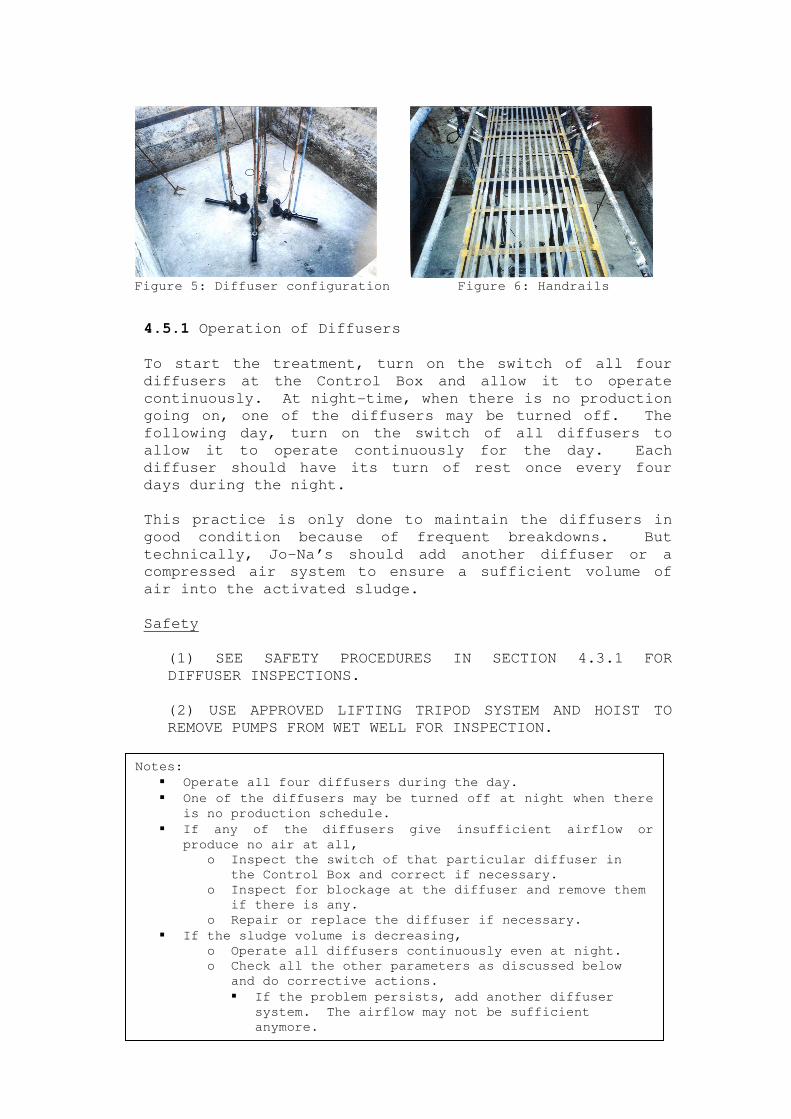
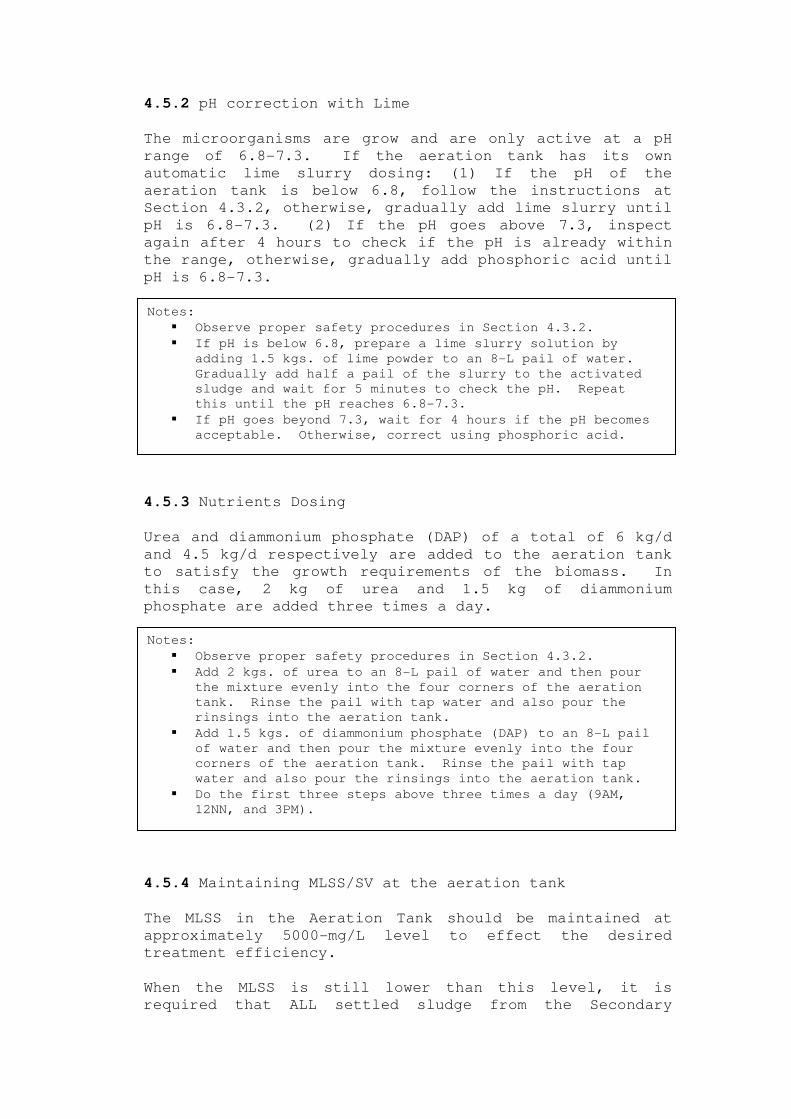
4.5.1 Operation of Diffusers
To start the treatment, turn on the switch of all four
diffusers at the Control Box and allow it to operate
continuously. At night-time, when there is no production
going on, one of the diffusers may be turned off. The
following day, turn on the switch of all diffusers to
allow it to operate continuously for the day. Each
diffuser should have its turn of rest once every four
days during the night.
This practice is only done to maintain the diffusers in
good condition because of frequent breakdowns. But
technically, Jo-Na’s should add another diffuser or a
compressed air system to ensure a sufficient volume of
air into the activated sludge.
Safety
(1) SEE SAFETY PROCEDURES IN SECTION 4.3.1 FOR
DIFFUSER INSPECTIONS.
(2) USE APPROVED LIFTING TRIPOD SYSTEM AND HOIST TO
REMOVE PUMPS FROM WET WELL FOR INSPECTION.
Notes:
� Operate all four diffusers during the day.
� One of the diffusers may be turned off at night when there
is no production schedule.
� If any of the diffusers give insufficient airflow or
produce no air at all,
o Inspect the switch of that particular diffuser in
the Control Box and correct if necessary.
o Inspect for blockage at the diffuser and remove them
if there is any.
o Repair or replace the diffuser if necessary.
� If the sludge volume is decreasing,
o Operate all diffusers continuously even at night.
o Check all the other parameters as discussed below
and do corrective actions.
� If the problem persists, add another diffuser
system. The airflow may not be sufficient
anymore.
Figure 5: Diffuser configuration Figure 6: Handrails
4.5.2 pH correction with Lime
The microorganisms are grow and are only active at a pH
range of 6.8-7.3. If the aeration tank has its own
automatic lime slurry dosing: (1) If the pH of the
aeration tank is below 6.8, follow the instructions at
Section 4.3.2, otherwise, gradually add lime slurry until
pH is 6.8-7.3. (2) If the pH goes above 7.3, inspect
again after 4 hours to check if the pH is already within
the range, otherwise, gradually add phosphoric acid until
pH is 6.8-7.3.
4.5.3 Nutrients Dosing
Urea and diammonium phosphate (DAP) of a total of 6 kg/d
and 4.5 kg/d respectively are added to the aeration tank
to satisfy the growth requirements of the biomass. In
this case, 2 kg of urea and 1.5 kg of diammonium
phosphate are added three times a day.
4.5.4 Maintaining MLSS/SV at the aeration tank
The MLSS in the Aeration Tank should be maintained at
approximately 5000-mg/L level to effect the desired
treatment efficiency.
When the MLSS is still lower than this level, it is
required that ALL settled sludge from the Secondary
Notes:
� Observe proper safety procedures in Section 4.3.2.
� If pH is below 6.8, prepare a lime slurry solution by
adding 1.5 kgs. of lime powder to an 8-L pail of water.
Gradually add half a pail of the slurry to the activated
sludge and wait for 5 minutes to check the pH. Repeat
this until the pH reaches 6.8-7.3.
� If pH goes beyond 7.3, wait for 4 hours if the pH becomes
acceptable. Otherwise, correct using phosphoric acid.
Notes:
� Observe proper safety procedures in Section 4.3.2.
� Add 2 kgs. of urea to an 8-L pail of water and then pour
the mixture evenly into the four corners of the aeration
tank. Rinse the pail with tap water and also pour the
rinsings into the aeration tank.
� Add 1.5 kgs. of diammonium phosphate (DAP) to an 8-L pail
of water and then pour the mixture evenly into the four
corners of the aeration tank. Rinse the pail with tap
water and also pour the rinsings into the aeration tank.
� Do the first three steps above three times a day (9AM,
12NN, and 3PM).
Clarifier be returned to the aeration tank to ensure
sufficient population of microorganisms to eat up the
organic matter. This is called return activated sludge
(RAS).
When the MLSS is higher than this level, it is required
to draw out appropriate volume of settled sludge from the
Secondary Clarifier leading to the sludge drying bed to
reduce the mass of sludge returned to the Aeration Tank.
This is called waste activated sludge (WAS).
In order to determine the amount of sludge to be drawn
out, the operator will require to carry out settling test
on the Aeration Tank activated sludge sample using a 1-
liter Imhoff cone every morning when the production line
was in operation the day before. The test results will
then be used to estimate the volume of settled sludge to
be drawn out from the Secondary Clarifier.
A simple operational procedure has been developed and is
summarised below to assist the operator to carry out the
test and estimate the volume of sludge to be drawn out
for disposal.
1. Collect 1 litre sample of activated sludge from the Aeration Tank.
2. Pour the sample into a 1-liter Imhoff cone. 3. After 30 minutes of settling measure the volume of settled sludge.
The reading, which is the sludge volume, should be at a
range of 700-800 mL/L. Above 850, open the waste
activated sludge line for 3 minutes, instead of going to
the return activated sludge line. Continue wasting until
the sludge volume reaches a little less than 800 mL/L.
Notes:
� Monitor and record the sludge volume using the Imhoff
cone.
o Collect two 1-L sample from the aeration tank.
o Pour into the Imhoff cones.
o Get the reading after 30 minutes.
� In case the SV is within the 700-800 range, continue with
the operation.
o If SV is below 700, return all settled sludge from
the secondary clarifier to the aeration tank and
check other parameters such as pH, diffusers, and
records of nutrient amendments (urea and DAP).
� It is also important to check whether CIP
(cleaning-in-place) is done only at one
schedule within the day. Antibacterial
solutions and chlorine can kill all the
activated sludge at one abrupt discharge.
o If SV goes beyond 850, gradually waste the sludge
through the WAS line going to the drying beds.
4.5.5 Additional pointers
Ensure that the diffusers are running all the time 24
hours a day and 7 days a week, except for provisions
discussed in Section 4.5.1.
Do not throw away the contents of the aeration tank! It
takes 6 months to a year to grow and acclimate the
biomass.
Remove any floating material at the surface of the
aeration tank as it may block the sunlight. Removing the
floating scum will also promote surface aeration of the
activated sludge using wind forces.
Regularly inspect the water level at the aeration tank,
as the present diffusers may not be able to accommodate a
high water level.
4.5.6 Pumping into Secondary Clarifier
Wastewater coming from the aeration tank should be
transferred to the secondary clarifier to separate the
activated sludge from the clean or treated water. A 1-Hp
pump is used to deliver wastewater at a rate of 32 L/min,
a flowrate good enough to promote undisturbed and better
settling of the sludge.
The pump should operate continuously.
Safety
(1) SEE SAFETY PROCEDURES IN SECTION 4.3.3 FOR PUMP
OPERATIONS.
Faults
(1) SEE POSSIBLE CAUSES OF PUMP FAILURE IN SECTION
4.3.3 FOR PUMP OPERATIONS.
Notes:
� Free the aeration tank from scum and other floating
materials.
� Regularly inspect the water level.
� Do not throw away the contents of the aeration tank at any
time! It takes 6 months to a year to grow and acclimate
the biomass.Exceptional cases would be for irreparable
system error inside the tank, as declared by the Pollution
Control Officer (PCO).
Notes:
� Observe proper safety procedures.
� Operate the pump continuously.
� Check for faults, as described above, and repair if
necessary.
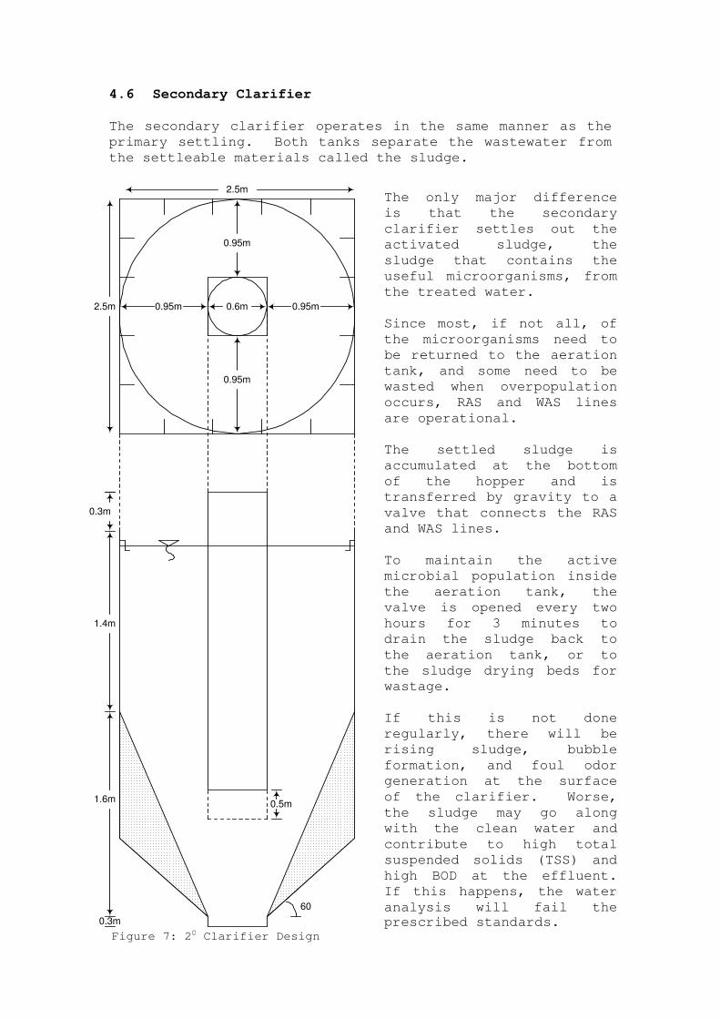
4.6 Secondary Clarifier
The secondary clarifier operates in the same manner as the
primary settling. Both tanks separate the wastewater from
the settleable materials called the sludge.
0.6m
2.5m
2.5m
1.4m
0.3m
0.95m 0.95m
0.95m
0.95m
1.6m
60
0.3m
0.5m
The only major difference
is that the secondary
clarifier settles out the
activated sludge, the
sludge that contains the
useful microorganisms, from
the treated water.
Since most, if not all, of
the microorganisms need to
be returned to the aeration
tank, and some need to be
wasted when overpopulation
occurs, RAS and WAS lines
are operational.
The settled sludge is
accumulated at the bottom
of the hopper and is
transferred by gravity to a
valve that connects the RAS
and WAS lines.
To maintain the active
microbial population inside
the aeration tank, the
valve is opened every two
hours for 3 minutes to
drain the sludge back to
the aeration tank, or to
the sludge drying beds for
wastage.
If this is not done
regularly, there will be
rising sludge, bubble
formation, and foul odor
generation at the surface
of the clarifier. Worse,
the sludge may go along
with the clean water and
contribute to high total
suspended solids (TSS) and
high BOD at the effluent.
If this happens, the water
analysis will fail the prescribed standards.
Figure 7: 2O Clarifier Design
The WWTP operator may follow the instructions and safety
procedures as discussed in Section 4.4.1. In case of
removing the settled sludge from the clarifier, the operator
should merely inspect for blockage along the gravity
transfer line to RAS and WAS.
4.7 Rapid Sand Filter
The rapid sand filter is used to further remove any
suspended solids from the clear water. However, the sand
filter needs to be backwashed whenever the pressure
differential reaches 10 psi. The initial pressure going to
the filter tank and the pressure loss inside the tank. Sand
filter will be backwashed at the flow rate of 27.5 gallons
per minute for 15 minutes. The backwash water will be
deviated back to the neutralization tank.
4.8 Slow Sand Filter with Activated Carbon
The slow sand filter has the same purpose as the rapid sand
filter with the objective of removing the residual or finer
solids that the rapid sand filter has missed. The activated
carbon inside the filter tank is used to further remove the
odor and color from the wastewater.
Notes:
� Ensure that RAS and WAS lines are not clogged.
o If clogged, repair the pipes.
o Use a submersible pump to clear out the sludge
completely.
� Check for any scum that rises at the surface of the tank.
o If present, skim the floating solids off the surface
and transfer them to sludge drying beds.
o Otherwise, there will be high TSS and BOD values in
the effluent analysis.
� To prevent the rising of solids,
o regularly open the valve leading to the RAS line to
return the activated sludge once every 2 hours for a
3-minute period or as soon as the RAS becomes clear.
o The WWTP operator should ensure that all the sludge
is removed from the secondary clarifier after each
production day before he goes home.
Notes:
� Ensure that the sand filter line is not clogged.
o If clogged, repair the line.
o Backwash, if necessary.
Notes:
� Ensure that the flow is not held back.
o Backwash if necessary.
o Regenerate the activated carbon.

5. ROUTINE MAINTENANCE
5.1 Screens
Inspect the screens every hour if the solids become
too much for the screens to handle. Replace or add a
successive screen with finer mesh when solids still
manage to pass through the slots.
5.2 Oil-Water Separator
Inspect the baffles inside the tank once on a daily
basis and cover any opening near the walls of the
tank. Replace the baffles when they become weak with
rust. Remove any coarse solids retained at the bottom
to avoid clogging of pipes and pumps as soon as
wastewater enters the equalization tank.
5.3 Equalization Tank
Inspect the tank once daily and remove any floating
coarse solids from the tank.
5.4 Primary Settling Tank
Inspect the tank once daily and remove any floating
solids from the tank. Ensure that the raw sludge is
removed once every 2 hours. If there is uneven flow
through all four sides of the v-notch weirs, adjust
the weirs.
5.5 Aeration Tank
Free the aeration tank from any material that had been
accidentally gone into the tank as they may cause
damage to diffusers. Remove all floating material
from the tank every hour.
5.6 Secondary Clarifier
Inspect the tank once daily and remove any floating
solids from the tank. Ensure no blockage along the
line.
5.7 Pumps and Diffusers
Inspect all motorised equipment, which include
submersible pumps, mono pumps, chemical dosing pump,
compressor, air flow lines, and diffusers once daily.
During the operation, the following checks should be
made:

� Excessive or abnormal noise and vibration
� Temperature (by hand touch or any metering device)
of motor, casing, bearings, gearboxes and other
accessories
� Leakage from joints, pipes, valves and fittings
� Lubricant spillage or leakage
Once every month, the following checks should be made:
� Accumulated dust / dirt on the equipment
� Abnormal vibration of moving parts
� Voltage supply of the motor
� Running condition of the motor
� Tighten all electrical connections
Quarterly, the following checks should be made:
� Winding resistance of the motors
� Valve seats of chemical pumps
Once every year, the following checks should be made:
� Lubricant levels in gear boxes
� belt drives
� Machine guards and safety equipment
� Repaint all rusted portion if necessary
� Clean motor winding with motor cleaner and revarnish
if necessary.
Refer to the Maintenance Manual supplied by the
Manufacturer for maintenance procedures.
5.8 pH Controller
Check the pH reading of the pH controller once every
day. Collect a 500 mL sample from the equalization
and/or aeration tanks and measure its pH with the
calibrated pH meter in the laboratory. Compare the
reading obtained with that of the pH controller.
If the two readings are the same, no calibration of
the pH controller is required. If the two readings
are different, calibrate the pH controller in the
Control Box. Refer to the calibration procedure in
the Maintenance Manual provided by the manufacturer.