Embed Size (px)
Citation preview


WASHINGTON DULLES INTERNATIONAL AIRPORT IT0702 MAIN TERMINAL EAST STORM WATER PUMPING STATION REHABILITATION NOVEMBER 7, 2008
SECTION 007300 — SUPPLEMENTARY CONDITIONS
PART 1 - GENERAL
1.1 RELATED DOCUMENTS
A. Drawings, Contract Provisions, Special Provisions, and other Division 01 Specification Sections, apply to this Section.
1.2 SUMMARY
A. The articles and paragraphs of this Section represent supplements or additions to the Contract Provisions or the Special Provisions.
1.3 WORK UNDER OTHER CONTRACTS
A. During the period of this Project, the contractor shall cooperate fully with other contractors working in the area. It is the contractor’s responsibility to contact the Authority prior to start of construction to identify any such activity in the area.
1.4 PERMITTING
A. Comply with all requirements set forth in the Authority's “Building Codes Manual”. This manual describes Building Codes organization, Construction permitting process, Building Code inspection process, Certificate of Occupancy requirements, and information regarding elevators, escalators, and moving walks.
1.5 MAINTENANCE OF PEDESTRIAN AND VEHICULAR TRAFFIC
A. Maintain adequate pedestrian and vehicular traffic flow and safety along the service roads, sidewalks, parking lots and other roadways on Airport property. In addition, this requirement applies to crossroads, approaches, and entrances affected by or made necessary by the Work. Coordinate activities throughout the project in a manner that allows emergency access, without delays to emergency response vehicles, to all areas of the Project that are occupied by employees.
B. Comply with requirements indicated in the Traffic Maintenance Plan provided in the contract documents. Obtain the Authority's written approval prior to implementing any deviations from the provided plan.
C. Prior to starting construction operations affecting pedestrian or vehicular traffic movement, submit and obtain the Authority’s written approval of a Traffic Maintenance Plan. Develop plan in accordance with the safety requirements of the Commonwealth of Virginia Department of Transportation’s “Manual of Uniform Traffic Control Devices”. Utilize the form indicated in the latest edition of the Virginia Department of Transportation’s “Virginia Work Area Protection Manual – Standards and Guidelines”.
SUPPLEMENTARY CONDITIONS 007300 - 1

WASHINGTON DULLES INTERNATIONAL AIRPORT IT0702 MAIN TERMINAL EAST STORM WATER PUMPING STATION REHABILITATION NOVEMBER 7, 2008
D. Provide and maintain temporary signage, "Jersey barriers," and such other traffic control devices or personnel as required complying with approved Traffic Maintenance Plan.
E. Maintain the construction operations affecting pedestrian or vehicular traffic movement from the beginning of construction operations until final acceptance of the project. The maintenance shall constitute continuous and effective work prosecuted day by day with adequate equipment and forces to the end of project to ensure that roadways and structures are maintained in satisfactory condition at all times, including barricades and warning signs as necessary for performance of the work.
F. Keep the portions of the project being used by public, pedestrian, and vehicular traffic, whether it is through or local traffic, in such condition that traffic will be adequately accommodated. Remove snow and control all ice within the project boundaries. Removal of snow and ice for the benefit of the traveling public will be performed by the Authority. Bear all cost of maintenance work during construction for constructing and maintaining approaches, crossings, intersections and other features as may be necessary.
G. Keep the portions of the road being used by the public free from irregularities, obstructions, mud, dirt, snow, ice, and any characteristic that might present a hazard or annoyance to traffic in such condition that traffic will be adequately accommodated. Maintain a vacuum/sweeper and flusher truck at the site at all times to clean roadway and aircraft surfaces affected by construction traffic at the request of Airport Operations or the Authority `
1.6 TERMINAL BUILDING OPERATIONAL REQUIREMENTS
A. The Work, or a portion thereof, will be performed within and nearby the public Terminal or Concourse buildings. Normal airport operations and public activities will continue adjacent to the Work during all phases of the Project. These include:
1. Passenger enplaning and deplaning. 2. Passenger baggage deposit/retrieval. 3. Ground transportation arrivals/departures. 4. Maintenance, custodial and support activities.
B. Phase construction activities as necessary to accommodate all airport operations without disruption. Adhere to all current Airport Orders and Instructions (O & Is), Airport Bulletins, and Airport Advisories. The Authority will provide relevant Orders and Instructions to Offerors in the Solicitation Package. Bulletins and Advisories will be provided to the offeror by the Authority as they are issued.
1.7 ENVIRONMENTAL PROTECTION
A. Comply with all Federal, state and local laws and regulations controlling pollution of the environment. Take necessary precautions to prevent pollution of streams, rivers, lakes, ponds, and reservoirs with fuels, oils, bitumens, chemicals, or other harmful materials and to prevent pollution of the atmosphere from particulate and gaseous matter.
B. Notify the Authority immediately in the event that abnormalities, discolorations, odors, oil, or other signs of potential contamination by hazardous materials are encountered during
SUPPLEMENTARY CONDITIONS 007300 - 2

WASHINGTON DULLES INTERNATIONAL AIRPORT IT0702 MAIN TERMINAL EAST STORM WATER PUMPING STATION REHABILITATION NOVEMBER 7, 2008
excavation or other construction activities. Follow with written notice within 24 hours, indicating date, time, and location of potential contaminants encountered. The Authority will provide further direction to Contractor regarding disposition of materials encountered.
C. All painted surfaces are assumed to contain lead-based paint. The Contractor shall maintain the necessary health and safety requirements for all personnel in accordance with OSHA regulations to work in these conditions. The removal and disposal of lead-based paint is part of this contract.
D. Petroleum contaminated soils and water may be encountered during the construction of this project. Petroleum impacted soils range from saturated to 1.0 ppm. Petroleum impacted water ranges from free product to “non - detect.” Maintain the necessary health and safety requirements for all personnel in accordance with OSHA regulations.
1. Do not use petroleum-contaminated soils as backfill around new piping or utilities. Transport petroleum contaminated soils to a location identified by the Authority. Place the contaminated soils on two layers of reinforced 6 mil plastic sheeting, install and maintain sediment and erosion controls, and adequately cover the stockpile to prevent water infiltration.
1.8 DAMAGES AND PRE-EXISTING CONDITIONS
A. Be responsible for all damages caused by Contractor’s construction activities. Provide all labor, materials, etc. to return any damaged areas, systems or equipment to their original condition at no additional cost to the Authority.
B. Perform a survey of pre-existing conditions in the vicinity of Contractor’s construction activities, utilizing photographs and other means as necessary to document existing damage or conditions. Submit two copies of this survey to the Contracting Officer within 21 calendar days after Notice-to-Proceed. This survey will assist in resolving any damage claims against the Contractor during and after construction.
C. Preserve all roadways, pedestrian and directional signage. Deliver all signs removed and not required for reinstallation to the Authority.
D. Replace or repair lost or damaged signs at no cost to the Authority.
1.9 SECURITY DURING CONSTRUCTION
A. Maintain the integrity of the Airport Security fence. Maintain the integrity of doors and walls between public areas and Air Operations Area (AOA) at all times. Comply with Title 49 Code of Federal Regulations, Parts 1500, 1540, 1542 and 1544.
B. Possession of and display of a proper and current Airport Identification Badge, issued by Airport Operations is required for all Contractor personnel passing into the AOA. Refer to "Airport Orders and Instructions" attached as part of the Contract for specific requirements. Security requirements have increased significantly at Washington Dulles International Airport. Contractor can expect up to two hours waiting time to clear construction vehicles into the AOA.Offerors shall become intimately familiar with all TSA and Authority security requirements.
SUPPLEMENTARY CONDITIONS 007300 - 3

WASHINGTON DULLES INTERNATIONAL AIRPORT IT0702 MAIN TERMINAL EAST STORM WATER PUMPING STATION REHABILITATION NOVEMBER 7, 2008
No increase in contract price will be provided to the Contractor should the contractor not be aware of any security procedure in place at time of submitting their offer that leads to increased time and inconvenience to accomplish the work.
C. Pay all fines levied by the Transportation Security Administration for penalties resulting from security infractions perpetrated by or caused by Contractor’s personnel or work forces of Contractor’s subcontractors or suppliers.
D. Establish and maintain the security of Contractor’s staging areas, equipment and materials.
E. Do not park within 300 feet of a terminal building unless specifically authorized by Airport Operations.
F. All workers in the sterile areas, which are defined as areas accessible to ticketed passengers only, may utilize tools in their work provided that:
1. Tools are essential and necessary to the Work. 2. Keep tools controlled at all times. 3. Do not leave tools unattended. 4. Store tools in locked boxes.
G. No knives will be permitted in the sterile areas.
H. When Work involves need for access to restricted areas under jurisdiction of U.S. Customs & Border Protection (CBP), secure necessary special security clearances to operate in the International Arrivals Building areas as prescribed by the U.S. Customs & Border Protection. Each company working in the CBP area shall apply for and obtain a bond from the CBP.
I. No firearms or weapons of any type are allowed on the airport.
J. No cartridge style nail guns, nor any tools that use a cartridge or any explosive charge, are allowed without prior written notification of the Authority. Obtain written approval from the Authority before bringing such tools on the project.
1.10 RADIO COMMUNICATIONS
A. Provide two-way radio communication between certain of the Contractor’s personnel on the job site. Provide radios with a minimum of 5 watts transmitting power. Select the frequency utilized for these transmissions. Submit proposed frequencies to the Authority in writing for approval.. Frequencies shall not conflict with or overlay any of the Airports radio frequencies.
B. Provide, at a minimum, the following with radio equipment: The Project Superintendent, Foreman of all work groups physically separated from the general vicinity of the Project Superintendent, and others who may be working in a separate and remote area.
1.11 SAFETY
A. Comply with all requirements set forth in the most current edition of the Authority Construction Safety Manual”. Offerors are provided with the most recent addition when obtaining contract documents prior to proposal. Requirements included in this Section are in addition to the
SUPPLEMENTARY CONDITIONS 007300 - 4
WASHINGTON DULLES INTERNATIONAL AIRPORT IT0702 MAIN TERMINAL EAST STORM WATER PUMPING STATION REHABILITATION NOVEMBER 7, 2008
Authority’s Construction Safety Manual. Comply with all local, State and Federal requirements. Where conflicts or discrepancies exist between requirements, the more stringent requirement shall govern. For additional information see Division 01 Section “Quality Requirements”.
B. Contractor Safety Organization:
1. Safety Engineer.
a. Duties: Outlined in The Authority Construction Safety Manual.b. Qualifications: Outlined in The Authority Construction Safety Manual.
C. Submit the résumés of individuals proposed to serve in the role of Contractor’s Safety Engineer, and Safety Supervisor to the Authority for approval in writing. In addition to indicating the qualifications in the Authority Construction Safety Manual résumés shall include but not be limited to such items as: work experience, education, safety and health training completed, memberships in professional associations, professional certifications, professional registrations and professional references confirming the qualifications and personal references of contacts for verification shall also be required.
D. Provide safe and healthful working conditions on each operation at all times during execution the work of this Contract. Conduct the various operations connected with the Work so that they will not be injurious to safety or health. Comply with all provisions, regulations and recommendations issued pursuant to the Occupational Safety and Health Act of 1970 and the Construction Safety Act of 1969, as well as amendments to these laws. Comply with laws, rules and regulations of other authorities having jurisdiction, with regard to all matters relating to the safety and health of workers and the general public. Compliance with government requirements is mandated by law and considered only a minimum level of safety performance. Perform all work in accordance with best safe work practices recognized by the construction industry. Stop work whenever a work procedure or a condition at a work site is deemed unsafe by the either of the following individuals: Authority, Program Safety Manager (PSM), the Contractor’s Project Manager, the Contractor’s Foreman, and the Contractor’s Safety Engineers.
E. Provide a full-time on-site Contractor Safety Engineer for the duration of this Contract. The Safety Engineer shall be responsible for all safety and health requirements as included herein and as required by the Authority’s Construction Safety Manual. If night shift work is short-term, less than 30 days duration and 15 craft workers or less, a Safety Supervisor may be used in lieu of Safety Engineer if approved by the Program Safety Manager. Résumé submission and interview by the Program Safety Manager is required and if approved, the Safety Supervisor reports directly to and is supervised by the contractors approved Safety Engineer. The Safety Supervisor shall be experienced in the craftwork being performed.
F. The contractor shall submit the resumes of all proposed safety and health professionals who shall serve in the role of Contractor’s Safety Engineers to the Authority for approval. The resumes shall include, but not be limited to such items as: work experience, education, safety and health training completed, memberships in professional associations, professional certifications, professional registrations, and professional references confirming the qualifications shall also be required. Documentation confirming the qualifications and personal references of contacts for verification shall also be required.
SUPPLEMENTARY CONDITIONS 007300 - 5

WASHINGTON DULLES INTERNATIONAL AIRPORT IT0702 MAIN TERMINAL EAST STORM WATER PUMPING STATION REHABILITATION NOVEMBER 7, 2008
G. Comply with all requirements set forth in the Authority's "Construction Safety Manual." Provide during the Work the services of Safety Engineer as outlined in the Authority’s “Construction Safety Manual” and in Division 01 Section “Quality Requirements.” The Safety Engineer shall undertake the duties and responsibilities as stated in the Authority's "Construction Safety Manual."
H. Flagmen Training: The Authority will sponsor Flagman training sessions. Contractor's personnel who will be assigned flagmen duties on the Airport for this project shall attend training sessions.
I. Fire Safety: Conform to the following requirements:
1. Obtain a permit to perform any welding, cutting, or hot work from the Office of the Authority Fire Marshal.
2. Ensure adequate access to all construction areas for emergency response. 3. Obtain a permit from the Office of the Authority Fire Marshal to store, handle, or use any
hazardous material, including but not limited to fuels for equipment. Complete an application prior to issuance.
4. Remove combustible debris from the site daily. 5. Provide at least seven (7) days notice for any request for inspections, tests, permits, etc.,
required of personnel from the Office of the Authority Fire Marshal. 6. Provide to the Office of the Authority Fire Marshal a list of emergency contact numbers
prior to the commencement of Work.
J. Submit Site-Specific Safety and Health Plans to the Authority within 15 calendar days of Notice to Proceed and prior to the start of any construction activities. Prepare this plan using the Authority’s Guidelines as defined in the Authority’s “Construction Safety Manual” and as supplemented by these specifications for each and every work zone as shown on the drawings or as anticipated by the Contractor. Authority must approve the Site-Specific Safety Plan prior to the start of any work.
K. Be responsible for the safe operation of all job site motor vehicles. Provide a “spotter” or flagman for all backing operations of construction vehicles with restricted rear vision.
L. All motorized equipment and vehicles working on or entering MWAA construction project work areas shall be equipped with functional audible backup alarms.
M. Crane Operators. On Airports Authority projects, Crane Operators shall be certified to operate the equipment by an approved independent certifying agency.
1.12 HEIGHT LIMITATION
A. For all demolition and construction within the Airport, limit the height of Contractor's equipment to a maximum of 35 feet.
B. Prior to beginning any work coordinate with the Authority the height of all cranes, boom trucks, scaffolds or similar vehicles of construction. Properly mark all construction equipment with safety flags and warning lights in accordance with current FAA and Airport Operations requirements. Submit FAA Form 7460, provided by the Authority, for all variations on approved crane heights.
SUPPLEMENTARY CONDITIONS 007300 - 6

WASHINGTON DULLES INTERNATIONAL AIRPORT IT0702 MAIN TERMINAL EAST STORM WATER PUMPING STATION REHABILITATION NOVEMBER 7, 2008
1.13 NOISE CONTROL
A. The Authority recognizes and can tolerate a normal level of noise created by a majority of construction activity. However, in the interest of the Authority's neighbors, the maximum acceptable noise level between the hours of 5:00 pm and 7:00 am the following morning is limited to 55 decibels. During daytime hours of 7:00 am through 5:00 pm, the maximum acceptable noise level for sustained or repetitive noises is 72 decibels. Measure the noise level using an "A" scale at a point 4'-0" above ground at property line nearest noise source.
B. Secure advance written approval from the Authority prior to scheduling any activity that is anticipated to produce a sustained or repetitive noise level higher than the decibel limits indicated above.
C. In and around terminal facilities and buildings whose normal occupancy is from 7 a.m. to 7 p.m., perform work that causes noise that is disruptive to the airport’s tenants or the traveling public between the hours of 11:00 pm and 5:00 am. Measure noise for this situation using an “A” scale at a point 4’-0” above ground at the closest point to airport tenants or the traveling public.
1.14 EXAMINATION OF PLAN, SPECIFICATIONS AND SITE OF WORK
A. The offeror is expected t examine carefully the site of the proposed work, the proposal, plans, specifications, solicitation provisions, contract provisions, special provisions and contract forms before submitting a proposal. The submission of a proposal will be considered conclusive evidence that the offeror has made such examination and is satisfied as t the conditions to be encountered in performing the work as to the requirements of the Contract.
PART 2 - PRODUCTS (Not Used)
PART 3 - EXECUTION (Not Used)
END OF SECTION 007300
SUPPLEMENTARY CONDITIONS 007300 - 7

WASHINGTON DULLES INTERNATIONAL AIRPORT IT0702 MAIN TERMINAL EAST STORM WATER PUMPING STATION REHABILITATION NOVEMBER 7, 2008
THIS PAGE INTENTIONALLY LEFT BLANK
SUPPLEMENTARY CONDITIONS 007300 - 8

WASHINGTON DULLES INTERNATIONAL AIRPORT IT0702 MAIN TERMINAL EAST STORM WATER PUMPING STATION REHABILITATION NOVEMBER 7, 2008
SECTION 011000 - SUMMARY
PART 1 - GENERAL
1.1 RELATED DOCUMENTS
A. Drawings, Contract Provisions, Special Provisions, Supplementary Conditions, and other Division 01 Specification Sections apply to this Section.
1.2 SUMMARY
A. This Section includes the following:
1. Work covered by the Contract Documents. 2. Type of the Contract. 3. Work phases. 4. Work under other contracts. 5. Products ordered in advance. 6. Authority-furnished products. 7. Use of premises. 8. The Authority's occupancy requirements. 9. Work restrictions. 10. Specification formats and conventions.
B. Related Sections include the following:
1. Division 01 Section "Temporary Facilities and Controls" for limitations and procedures governing temporary use of the Authority's facilities.
1.3 WORK COVERED BY CONTRACT DOCUMENTS
A. Project Identification: Project consists of rehabilitating the Main Terminal East Storm Water Pumping Station. Details are as described in Paragraph E below.
1. Project Location: Washington Dulles International Airport.
B. Architect/Engineer Identification: The Contract Documents, dated November 2008, were prepared for Project by Burns Engineering, Inc, .6700 Old McLean Village Drive, Suite 201, McLean, Virginia 22101.
C. Construction Manager: Airport Authority.
SUMMARY 011000 - 1

WASHINGTON DULLES INTERNATIONAL AIRPORT IT0702 MAIN TERMINAL EAST STORM WATER PUMPING STATION REHABILITATION NOVEMBER 7, 2008
D. The Work consists of providing of all labor, materials, equipment and incidentals for replacement of storm water pumping station waste water pumps, sump pumps, pump control panel, associated electrical, communications and controls, pump discharge piping and valves, and general construction work for rehabilitation of the East Storm Water Pumping Station, including all appurtenances as shown on drawings and or specified.
1. The Work includes removal of existing column type storm water pumps, sump pumps, variable frequency drive control panel, pump discharge piping and valves, and associated electrical components located in underground pumping station equipment vault.
Replacement pumping system will include submersible type waste water pumps wet well sump pump, pump discharge piping and valves, remote mounted control panel, associated electrical and communications devices and equipment, and general construction work. Existing ten inch storm water header located within each station will be reused in new work.
2. For additional requirements for the examination of plans, specifications, and Project site see Section "Supplementary Conditions."
1.4 TYPE OF CONTRACT
A. Project will be constructed under a mechanical construction contract.
1.5 USE OF PREMISES
A. Use of Site: Limit use of premises to work in areas indicated. Do not disturb portions of site beyond areas in which the Work is indicated.
1. Authority Occupancy: Allow for Authority occupancy of site and day-to-day use by d the public.
2. Contractor shall have full use of premises for construction operations within the Contract Limit Lines indicated during construction period, during the hours indicated, and as directed by the Authority. Contractor's use of premises is limited only by the Authority's right to perform work or to retain other contractors on portions of Project.
3. Roadways: Keep roadways clear and available to the Authority, the Authority's employees, tenants, air carriers, and emergency vehicles at all times. Do not use roadways for parking or storage of materials.
a. Schedule deliveries to minimize use of roadways. b. Schedule deliveries to minimize space and time requirements for storage of
materials and equipment on-site.
SUMMARY 011000 - 2

WASHINGTON DULLES INTERNATIONAL AIRPORT IT0702 MAIN TERMINAL EAST STORM WATER PUMPING STATION REHABILITATION NOVEMBER 7, 2008
1.6 CONTRACTOR HOURS OF OPERATION
A. Contractor Working Hours: The Authority anticipates that the Contractor may be required to work multiple shifts to accomplish the work of this Contract within the established schedule. Contractor will be allowed and may be required by the nature of the Project to work 24 hours a day, seven days a week in the performance of the Work. Work is subject to restrictions of the Airport operational requirements. Notify the Authority 24-hours in advance of any change to the work schedule.
1.7 SPECIFICATION FORMATS AND CONVENTIONS
A. Specification Format: With the exception of Federal Aviation Administration (FAA) standard specifications and Virginia Department of Transportation standard specifications the Specifications are organized into Divisions and Sections using the 33-Division format using the CSI/CSC's "MasterFormat 2004" numbering system.
1. Section Identification: The Specifications use Section titles to help with cross-referencing in the Contract Documents. Sections in the Project Manual are in numeric sequence; however, the sequence is incomplete as all available Sections and Section numbers are not used and the CSI numbering system is not sequentially complete. Consult the table of contents at the beginning of the Project Manual to determine numbers and names of sections in the Contract Documents.
B. Specification Content: The Specifications use certain conventions for the style of language and the intended meaning of certain terms, words, and phrases when used in particular situations. These conventions are as follows:
1. Abbreviated Language: Language used in the Specifications and other Contract Documents is abbreviated. Interpret words and meanings as appropriate. Infer words implied, but not stated, as the sense requires. Interpret singular words as plural, and plural words as singular where applicable as the context of the Contract Documents indicates.
2. Imperative mood and streamlined language are used in these Specifications. This imperative language is directed to the Contractor, unless specifically noted otherwise. Requirements expressed in the imperative mood are to be performed by Contractor. Occasionally, the indicative or subjunctive mood may be used in the Section Text for clarity to describe responsibilities that must be fulfilled indirectly by Contractor or by others when so noted.
a. The words "shall," "shall be," or "shall comply with," depending on the context, are implied where a colon (:) is used within a sentence or phrase.
SUMMARY 011000 - 3

WASHINGTON DULLES INTERNATIONAL AIRPORT IT0702 MAIN TERMINAL EAST STORM WATER PUMPING STATION REHABILITATION NOVEMBER 7, 2008
1.8 MARKING UTILITY SERVICES
A. Employ underground utilities location subcontractor to locate and mark the horizontal location of all utility lines that might be impacted by construction activities, including, but not limited to, the following:
1. Electric power lines. 2. Natural gas lines. 3. Sanitary Sewers. 4. Storm Sewers. 5. FAA communications, signal, and security lines. 6. Water supply piping. 7. Telephone lines. 8. Data lines. 9. Dedicated Fire System (DFS) lines.
B. Contact the Airport Communications System (ACS) Help Desk at (703) 417-8300 a minimum of 72 hours prior to starting activities that include but are not limited to location and marking of horizontal locations of telephone and telecommunications lines belonging to the Authority as part of the Airport Communication System. Contact the Airport Communications System (ACS) Help Desk a minimum of 72 hours prior to beginning operations, that include but are not limited to excavating, digging or planting. Note the ACS does not locate utilities. Location is the responsibility of the Contractor’s underground utilities location subcontractor. The Airport Communications System (ACS) is merely notified as indicated previously.
C. The information in the Contract Documents concerning the type and location of underground utilities is neither guaranteed nor inclusive. The Contractor is responsible for determining the type and location of underground utilities, regardless of whether such utilities are indicated or not, so as to avoid damage thereto.
D. Check and verify the horizontal and vertical location (coordinates and elevation) of all utility lines that may exist within the limits of new work, regardless of whether such utilities are indicated or not, by use of a Subsurface Utility Engineering company. Reconfirm such locations and verification of utilities discovered, regardless of whether such utilities are indicated or not, and submit to the Authority a dimensional survey with such notations.
E. Dig test pits by hand shovel in the vicinity of the discovered utilities. Excavate test holes utilizing a vacuum excavator.
F. Repair any damage to discovered utility lines due to construction operations at no expense to the Authority. The Authority will assist the Contractor by making available any known information.
G. Submit to the Authority, for written approval, the name of the independent subsurface utility engineering company to be used.
SUMMARY 011000 - 4

WASHINGTON DULLES INTERNATIONAL AIRPORT IT0702 MAIN TERMINAL EAST STORM WATER PUMPING STATION REHABILITATION NOVEMBER 7, 2008
H. The individual who performs the utility detection and location work shall have as a minimum five (5) years of similar experience in the area of subsurface utility detection and location engineering.
I. Submit to the Authority the following:
1. List of utility detection equipment along with product information and data sheets that will be used specifically for this contract.
2. List of employee qualifications and résumés of those individuals who will be assigned specifically to this contract.
3. Within 60 calendar days of Notice to Proceed, a survey of all subsurface utility engineering results indicating the horizontal and vertical location, coordinates and elevation of all utilities.
PART 2 - PRODUCTS (Not Used)
PART 3 - EXECUTION (Not Used)
END OF SECTION 011000
SUMMARY 011000 - 5

WASHINGTON DULLES INTERNATIONAL AIRPORT IT0702 MAIN TERMINAL EAST STORM WATER PUMPING STATION REHABILITATION NOVEMBER 7, 2008
THIS PAGE INTENTIONALLY LEFT BLANK
SUMMARY 011000 - 6

WASHINGTON DULLES INTERNATIONAL AIRPORT IT0702 MAIN TERMINAL EAST STORM WATER PUMPING STATION REHABILITATION NOVEMBER 7, 2008
SECTION 012900 – APPLICATION FOR PAYMENT
PART 1 - GENERAL
1.1 RELATED DOCUMENTS
A. Drawings, Contract Provisions, Special Provisions, Supplementary Conditions, and other Division 01 Specification Sections apply to this Section.
1.2 SUMMARY
A. This Section specifies administrative and procedural requirements necessary to prepare and process Applications for Payment.
1. Coordinate the Schedule of Values and Applications for Payment with Contract CPM Schedule, List of Subcontracts, and Submittal Log.
B. Related Sections include the following:
1. Division 01 Section "Construction Progress Documentation" for administrative requirements governing preparation and submittal of Contractor's Construction Schedule and Submittals Schedule.
2. Division 01 Section “Project Closeout” for submittal of items required before final payment.
3. Division 01 Section “Project Record Documents” for procedural requirements governing the submission of Project Record Documents.
4. Division 01 Section “Operation and Maintenance Data” for submittal of items required before final payment.
1.3 DEFINITIONS
A. Schedule of Values: A statement furnished by Contractor allocating portions of the Contract Price to various portions of the Work and once accepted, to be used as the basis for reviewing Contractor's Applications for Payment.
1.4 SCHEDULE OF VALUES
A. Coordination: Coordinate preparation of the Schedule of Values with preparation of Contractor's Construction Schedule.
1. Correlate line items in the Schedule of Values with other required administrative forms and schedules, including the following:
a. Application for Payment forms with Continuation Sheets. b. Submittals Schedule. c. Contract CPM Schedule.
APPLICATION FOR PAYMENT 012900 - 1
WASHINGTON DULLES INTERNATIONAL AIRPORT IT0702 MAIN TERMINAL EAST STORM WATER PUMPING STATION REHABILITATION NOVEMBER 7, 2008
d. List of products. e. List of principal suppliers and fabricators.
2. Submit the Schedule of Values to Contracting Officer at earliest possible date, but no later than 21 calendar days after the date of the Notice to Proceed.
a. On projects requiring cost-loaded CPM Schedules, the accepted cost loading will satisfy the requirements for the Schedule of Values.
B. Format and Content: Use the Project Manual table of contents as a guide to establish line items for the Schedule of Values. Provide at least one line item for each Specification Section.
1. Identification: Include the following Project identification on the Schedule of Values:
a. Project name and location. b. Name of Architect/Engineer. c. The Authority’s Project number. d. Contractor's name and address. e. Date of submittal.
2. Arrange the Schedule of Values in tabular form with separate columns to indicate the following for each item listed:
a. Related Specification Section or Division. b. Description of the Work. c. Name of subcontractor. d. Name of manufacturer or fabricator. e. Name of supplier. f. Contract Modifications (numbers) that affect value. g. Dollar value.
1) Percentage of the Contract Price to nearest one-hundredth percent, adjusted to total 100 percent.
3. Provide a breakdown of the Contract Price in enough detail to facilitate continued evaluation of Applications for Payment and progress reports. Coordinate with the Project Manual table of contents. Provide several line items for principal subcontract amounts, where appropriate. Include separate line items under required principal subcontracts for the following items. The value assigned to the total of these line items shall be 5 percent of the Contract Price:
a. Testing and commissioning activities. b. Operation and Maintenance manuals. c. Punch list activities. d. Project Record Documents. e. Bonds and warranties. f. Demonstration and training.
4. Round amounts to nearest whole dollar. Total shall equal the Contract Price.
APPLICATION FOR PAYMENT 012900 - 2
WASHINGTON DULLES INTERNATIONAL AIRPORT IT0702 MAIN TERMINAL EAST STORM WATER PUMPING STATION REHABILITATION NOVEMBER 7, 2008
5. Provide a separate line item in the Schedule of Values for each part of the Work where Application for Payment may include materials or equipment purchased or fabricated and stored, but not yet installed.
a. Differentiate between potential items stored on-site and items stored off-site. Include evidence of insurance or bonded warehousing if required.
6. Provide separate line items in the Schedule of Values for initial cost of materials, for each subsequent stage of completion, and for total installed value of that part of the Work.
7. Each item in the Schedule of Values and Application for Payment shall be complete. Include total cost and proportionate share of general overhead and profit for each item.
a. At Authority’s option, temporary facilities and other major cost items that are not direct cost of actual work-in-place may be shown either as separate line items in the Schedule of Values or distributed as general overhead expense.
8. Schedule Updating: Update and resubmit the Schedule of Values with the next Applications for Payment when Contract Modifications result in a change in the Contract Price.
1.5 APPLICATION FOR PAYMENT
A. Each Application for Payment shall be consistent with previous applications and payments as certified by Contracting Officer and paid for by the Authority.
1. Initial Application for Payment, Application for Payment at time of Substantial Completion, and final Application for Payment involve additional requirements.
B. Payment Application Times: Application for Payment shall coincide with CPM schedule monthly update, or as otherwise indicated in the Agreement between the Authority and Contractor. The period covered by each Application for Payment starts on the day following the end of the preceding period and shall not exceed one calendar month, unless otherwise approved by the Authority.
C. Payment Application Forms: Use forms provided by the Contracting Officer, but supplied by the Authority for Application for Payment.
D. Application Preparation: Complete every entry on form. Notarize and execute by a person authorized to sign legal documents on behalf of Contractor. The Authority will return incomplete applications without action.
1. Entries shall match data on the Schedule of Values and Contractor's Construction Schedule. Use updated schedules if revisions were made.
2. Include amounts of Contract Modifications issued before last day of construction period covered by application.
E. Transmittal: Submit one original and four copies of Application for Payment to the address indicated in the Section VII - Contract Provision, paragraph 04.B, each one signed and notarized. Include waivers of lien and similar attachments if required.
APPLICATION FOR PAYMENT 012900 - 3

WASHINGTON DULLES INTERNATIONAL AIRPORT IT0702 MAIN TERMINAL EAST STORM WATER PUMPING STATION REHABILITATION NOVEMBER 7, 2008
1. Transmit Applications for Payment with a transmittal form listing attachments and recording appropriate information about application in a manner acceptable to Contracting Officer.
F. Waivers of Mechanic's Lien: With Final Application for Payment, submit waivers of mechanic's liens from subcontractors, sub-subcontractors, and suppliers.
1. The Authority reserves the right to designate which entities involved in the Work must submit waivers.
2. Waiver Forms: Submit waivers of lien on forms, executed in a manner acceptable to the Authority.
G. Initial Application for Payment: Administrative actions and submittals that shall precede or coincide with submittal of first Application for Payment include the following:
1. List of subcontractors. 2. Schedule of Values. 3. Contractor's Construction Schedule (preliminary if not final). 4. Products list. 5. Submittals Schedule (preliminary if not final). 6. List of Contractor's staff assignments. 7. List of Contractor's principal consultants. 8. Copies of building permits. 9. Copies of authorizations and licenses from authorities having jurisdiction for performance
of the Work. 10. Initial progress report. 11. Report of pre-construction conference. 12. Performance and payment bonds. 13. Initial settlement survey and damage report if required. 14. Submittal and approval of Contractor Safety Plan. 15. Subcontractor Payment Form: (Form J, "Contract Conditions," Section IX, "LDBE").
H. Monthly Application for Payment: Administrative actions and submittals that shall accompany the submittal of Contractor's monthly Application for Payment include the following:
1. Subcontractor Payment Form. 2. Monthly Progress Report, prepared according to requirements specified in Division 01
Section "Construction Progress Documentation." 3. Evidence of payment for material on-site if reimbursement for such material is being
requested.4. Updated Inspection Control Log. Highlight changes from previous month. 5. Update of Contract Record Documents.
I. Application for Payment at Substantial Completion: After issuance of the Certificate of Substantial Completion, submit an Application for Payment showing 100 percent completion for portion of the Work claimed as substantially complete.
1. Include documentation supporting claim that the Work is substantially complete and a statement showing an accounting of changes to the Contract Price.
2. This application shall reflect Certificates of Partial Substantial Completion issued previously for Authority occupancy of designated portions of the Work, if applicable.
APPLICATION FOR PAYMENT 012900 - 4
WASHINGTON DULLES INTERNATIONAL AIRPORT IT0702 MAIN TERMINAL EAST STORM WATER PUMPING STATION REHABILITATION NOVEMBER 7, 2008
3. Advise the Authority of change-over in security provisions.
J. Final Payment Application: Submit final Application for Payment with releases and supporting documentation not previously submitted and accepted, including, but not limited, to the following:
1. Evidence of completion of Project closeout requirements. 2. Insurance certificates for products and completed operations where required and proof
that taxes, fees, and similar obligations were paid. 3. Updated final statement, accounting for final changes to the Contract Price. 4. Evidence that claims have been settled. 5. Final, liquidated damages settlement statement. 6. Return of all Airport identification badges and keys.
PART 2 - PRODUCTS (Not Used)
PART 3 - EXECUTION (Not Used)
END OF SECTION 012900
APPLICATION FOR PAYMENT 012900 - 5
WASHINGTON DULLES INTERNATIONAL AIRPORT IT0702 MAIN TERMINAL EAST STORM WATER PUMPING STATION REHABILITATION NOVEMBER 7, 2008
THIS PAGE INTENTIONALLY LEFT BLANK
APPLICATION FOR PAYMENT 012900 - 6
WASHINGTON DULLES INTERNATIONAL AIRPORT IT0702 MAIN TERMINAL EAST STORM WATER PUMPING STATION REHABILITATION NOVEMBER 7, 2008
SECTION 013100 - PROJECT MANAGEMENT AND COORDINATION
PART 1 - GENERAL
1.1 RELATED DOCUMENTS
A. Drawings, Contract Provisions, Special Provisions, Supplementary Conditions, and other Division 01 Specification Sections apply to this Section.
1.2 SUMMARY
A. This Section includes administrative provisions for coordinating construction operations on Project including, but not limited to, the following:
1. General project coordination procedures. 2. Conservation. 3. Coordination drawings. 4. Administrative and supervisory personnel. 5. Project meetings.
a. Pre-award conference. b. Pre-construction conference. c. Pre-installation conference. d. Progress meetings.
B. Related Sections include the following:
1. Division 01 Section: "Execution " for the coordination of general installation and field-engineering services, including establishment of benchmarks and control points.
2. Division 01 Section "Project Closeout" for coordinating Contract closeout.
1.3 COORDINATION
A. Coordination: Coordinate construction operations included in various Sections of the Specifications to ensure efficient and orderly installation of each part of the Work. Coordinate construction operations, included in different Sections that depend on each other for proper installation, connection, and operation.
1. Schedule construction operations in sequence required to obtain the best results where installation of one part of the Work depends on installation of other components, before or after its own installation.
2. Coordinate installation of different components with other contractors to ensure maximum accessibility for required maintenance, service, and repair.
3. Where availability of space is limited, coordinate installation of different components to ensure maximum performance and accessibility for required maintenance, service, and repair of all components, mechanical, electrical, and otherwise. Contractor is cautioned that, where specific dimensions are not indicated or where Drawings are schematic in
PROJECT MANAGEMENT AND COORDINATION 013100 - 1

WASHINGTON DULLES INTERNATIONAL AIRPORT IT0702 MAIN TERMINAL EAST STORM WATER PUMPING STATION REHABILITATION NOVEMBER 7, 2008
nature, as with most Electrical and Mechanical Drawings, Contractor shall have sole responsibility to coordinate the work to meet this requirement. Prepare and submit Coordination Drawings to the Authority for review and approval as provided in "Coordination Drawings" Paragraph in "Submittals" Article of this Section.
4. Make adequate provisions to accommodate items scheduled for later installation.
B. Prepare memoranda for distribution to each party involved, outlining special procedures required for coordination. Include such items as required notices, reports, and list of attendees at meetings.
1. Prepare similar memoranda for the Authority and separate contractors if coordination of their Work is required.
C. Administrative Procedures: Coordinate scheduling and timing of required administrative procedures with other construction activities and activities of other contractors to avoid conflicts and to ensure orderly progress of the Work and completion within the specified Contract duration. Such administrative activities include, but are not limited to, the following:
1. Preparation of Contractor's Construction Schedule. 2. Preparation of the Schedule of Values. 3. Installation and removal of temporary facilities and controls. 4. Delivery and processing of submittals. 5. Progress meetings. 6. Pre-installation conferences. 7. Start-up, check-out, and final acceptance of systems. 8. Project closeout activities. 9. Protection of existing and new work.
D. Conservation: Coordinate construction activities to ensure that operations are carried out with consideration given to conservation of energy, water, and materials.
1. Salvage materials and equipment involved in performance of, but not actually incorporated into, the Work. Refer to other sections for disposition of salvaged materials that are designated as the Authority's property.
E. Temporary Utility Outages: Comply with requirements in Division 01 Section "Summary."
1.4 SUBMITTALS
A. Coordination Drawings: Before start of the Work, prepare Coordination Drawings for areas with limited space availability that necessitate maximum utilization of space for efficient installation of different components, and areas requiring coordination for installation of products and materials fabricated by separate entities.
1. Indicate relationship of components shown on separate Shop Drawings. 2. Indicate all dimensions provided on Contract Drawings and make specific note of
dimensions that appear to be in conflict with submitted equipment, minimum clearance requirements, amounts of equipment and material to be installed, or other requirements. Provide alternate sketches for resolution of such conflicts to the Authority for review.
PROJECT MANAGEMENT AND COORDINATION 013100 - 2
WASHINGTON DULLES INTERNATIONAL AIRPORT IT0702 MAIN TERMINAL EAST STORM WATER PUMPING STATION REHABILITATION NOVEMBER 7, 2008
Minor dimension changes and difficult installations shall not be considered changes to the Contract.
3. Indicate required installation sequences. 4. Comply with requirements contained in Division 01 Section "Submittals." 5. Prepare coordination drawings of involved trades in a scale of not less than 1/4 inch = 1
foot or larger for integration of different construction elements. Show sequences and relationships of separate components to avoid conflicts in use of space. Any Work installed prior to review of coordination drawings will be at the Contractor’s risk and subsequent relocation require to avoid interference shall be made at no additional cost to the Authority.
B. Key Personnel Names: At the pre-construction meeting, submit a list of Contractor's key personnel assignments. Key personnel shall include but not necessarily be limited to Project Manager, Project Superintendent, Safety Engineer, Quality Control Manager, Project Scheduler, Soil Excavation Engineers, and other personnel in attendance at Project site along with alternates. Identify individuals and their duties and responsibilities; list addresses and telephone numbers, including home and office telephone numbers. Provide names, addresses, and telephone numbers of individuals assigned as standbys in the absence of individuals assigned to Project.
1. Post copies of list in Project meeting room, in temporary field office, and by each temporary telephone. Keep the list current at all times.
1.5 ADMINISTRATIVE AND SUPERVISORY PERSONNEL
A. General: In addition to Project Superintendent, provide other administrative and supervisory personnel as required for proper performance of the Work.
1.6 PROJECT MEETINGS
A. Pre-award Conference:
1. General: At the request of the Contracting Officer, a pre-award conference with Contractor may be held before actual award of the Contract. The meeting will review Contractor's understanding of the Contract Documents, cost and pricing data, contractual requirements, and Contractor's capabilities, financial standing, and past experience prior to award.
a. Minutes: Authority will record and distribute meeting minutes to all attendees and all relevant parties.
2. Attendees: Contracting Officer, Authority Design Project Manager, Architect/Engineer, Contractor and its key personnel nominated for assignment to the Contract, and major subcontractors if so requested by the Contracting Officer. Concerned parties shall each be represented by persons thoroughly familiar with and authorized to conclude matters relating to the work described in the Contract Documents. The Contracting Officer will chair the pre-award meeting.
3. Agenda: Significant discussion items that could affect award include, but are not limited to, the following:
PROJECT MANAGEMENT AND COORDINATION 013100 - 3

WASHINGTON DULLES INTERNATIONAL AIRPORT IT0702 MAIN TERMINAL EAST STORM WATER PUMPING STATION REHABILITATION NOVEMBER 7, 2008
a. Provision and acceptability of payment and performance bonds. b. LDBE/MBE/WBE/DBE participation. c. Qualifications of key individuals. d. Quality-control experience. e. Percentage of work performed by own forces. f. Contractor's experience with similar work, including previous Authority contracts. g. Scheduling capabilities of Contractor. h. Financial standing of Contractor. i. Mobilization plan. j. Understanding of work described in the Contract Documents and the physical
constraints associated with work at the Airport. k. Equipment and manpower availability. l. Cost and pricing data.
4. Representations and commitments made by Contractor or its subcontractors shall be construed as binding to the Contract.
B. Pre-construction Conference:
1. General: Authority will schedule pre-construction conference and organizational meeting with Contractor after the Contracting Officer issues a notice of intent to award, or actually awards the Contract. The meeting will review the parties' responsibilities and personnel assignments.
a. Minutes: Authority will record and distribute meeting minutes to all attendees and relevant parties.
2. Attendees: Contracting Officer, the Authority, Architect/Engineer, and their sub-consultants; Contractor and its superintendent; major subcontractors; manufacturers; suppliers; and other concerned parties. All participants at the conference shall be familiar with Project and authorized to conclude matters relating to the Work.
3. Agenda: Discuss items of significance that could affect progress, including the following:
a. Airport security. b. LBDE/MBE/WBE/DBE participation and certifications. c. Authority-controlled wrap-up insurance program. d. Airport Operations coordination. e. Preliminary construction schedule. f. Critical work sequencing. g. Designation of key personnel. h. Procedures for processing field decisions and Contract Modifications. i. Procedures for processing Applications for Payment. j. Distribution of the Contract Documents. k. Authority Construction guidelines. l. Submittal procedures. m. Preparation of Record Documents. n. Use of the premises. o. Responsibility for temporary facilities and controls. p. Parking availability. q. Office, work, and storage areas.
PROJECT MANAGEMENT AND COORDINATION 013100 - 4

WASHINGTON DULLES INTERNATIONAL AIRPORT IT0702 MAIN TERMINAL EAST STORM WATER PUMPING STATION REHABILITATION NOVEMBER 7, 2008
r. Equipment deliveries and priorities. s. Safety procedures. t. Quality-control requirements. u. First aid. v. Progress cleaning. w. Working hours. x. Authority Building Code requirements/permits.
4. Refer to Contract Provision "Pre-construction Requirements" for required submittals due at the pre-construction conference.
C. Pre-installation Conferences:
1. General: The Authority will conduct a pre-installation conference at Project site before each construction activity that requires coordination with other construction.
a. Minutes: The Authority will record and distribute meeting minutes.
2. Attendees: Contractor, Installer, and representatives of manufacturers and fabricators involved in or affected by the installation and its coordination or integration with other materials and installations that have proceeded, or will follow.
3. Agenda: Review progress of other construction activities and preparations for the particular activity under consideration, including requirements for the following:
a. Contract Documents. b. Purchases.c. Deliveries.d. Submittals. e. Possible conflicts. f. Compatibility problems. g. Time schedules. h. Weather limitations. i. Manufacturer's written recommendations. j. Warranty requirements. k. Compatibility of materials. l. Acceptability of substrates. m. Temporary facilities and controls. n. Space and access limitations. o. Governing regulations and permits. p. Safety. q. Testing and inspecting requirements. r. Required performance results. s. Protection of construction and personnel. t. Review material selection. u. Fabrication and installation procedures. v. Coordination of involved trades.
4. Do not proceed with installation if the conference cannot be successfully concluded. Initiate whatever actions are necessary to resolve impediments to performance of the Work and reconvene the conference at earliest feasible date.
PROJECT MANAGEMENT AND COORDINATION 013100 - 5

WASHINGTON DULLES INTERNATIONAL AIRPORT IT0702 MAIN TERMINAL EAST STORM WATER PUMPING STATION REHABILITATION NOVEMBER 7, 2008
D. Weekly Progress Meetings:
1. General: The Authority will conduct progress meetings weekly at regularly scheduled times convenient for all parties involved. Progress meetings are in addition to specific meetings held for other purposes, such as coordination and special pre-installation meetings. Additionally, discussions will address administrative and technical issues of concern, determining resolutions, and development of deadlines for resolution within allowable time frames.
a. Minutes: The Authority will record and distribute meeting minutes.
2. Attendees: As may be required addition representatives of the Authority and Contractor, each subcontractor, supplier, Contractor’s Project Scheduler, and other entities concerned with current progress or involved in planning, coordination, or performance of future activities. All participants at the conference shall be familiar with Project and authorized to conclude matters relating to the Work.
3. Agenda: Review and correct or approve minutes of previous progress meeting. Review other items of significance that could affect progress. Include topics for discussion as appropriate to status of Project.
a. Contractor's Construction Schedule: Review progress since the last meeting. Determine whether each activity is on time, ahead of schedule, or behind schedule, in relation to Contractor's Construction Schedule. Determine how construction behind schedule will be expedited; secure commitments from parties involved to do so. Discuss whether schedule revisions are required to ensure that current and subsequent activities will be completed within the Contract Time.
b. Review present and future needs of each entity present, including the following:
1) Safety and Security. 2) Interface requirements. 3) Time. 4) Sequence of operations. 5) Status of submittals. 6) Deliveries.7) Off-site fabrication. 8) Storage Areas 9) Access. 10) Site utilization. 11) Requests for information. 12) Submittals. 13) Noncompliance notices. 14) Temporary facilities and controls. 15) Work hours. 16) Resource allocation. 17) Hazards and risks. 18) Progress cleaning. 19) Quality and work standards. 20) Contract Modifications. 21) Documentation of information for payment requests. 22) Preparation of Record Documents.
PROJECT MANAGEMENT AND COORDINATION 013100 - 6
WASHINGTON DULLES INTERNATIONAL AIRPORT IT0702 MAIN TERMINAL EAST STORM WATER PUMPING STATION REHABILITATION NOVEMBER 7, 2008
4. Submit at the weekly progress meeting, a two-week look-ahead schedule. This schedule shall include a three-week period, one week showing actual progress from the previous week and two weeks showing planned work for the two weeks after the meeting date. Include in the schedule all activities in sufficient detail as approved by the Authority. A two-week look-ahead schedule form will be distributed at the pre-construction conference. Submit a list of subcontractors identifying dates of when subcontractors will be on-site or off-site. A form for this information will be provided by the Authority.
5. Schedule Updating: Revise Contractor's Construction Schedule after each progress meeting where revisions to the schedule have been made or recognized. Issue revised schedule concurrently with the report of each meeting.
E. Schedule Update Meetings:
1. Conduct schedule update meetings before submittal of Contractor's Application for Payment. Determine where each activity is, in relation to Contractor's CPM Schedule. Ensure the incorporation of all changes made to the sequence of work and all change notices issued by the Contracting Officer. Submit the narrative and information specified in Division 01 Section "Construction Progress Documentation" if applicable.
2. Attendees: Contractor's Project manager or superintendent, the Contractor’s Project Scheduler, and the Authority's representative.
3. Submit the updated schedule, as bilaterally agreed on, along with the Application for Payment.
4. Present delay claims for discussion and, when possible, resolution.
PART 2 - PRODUCTS (Not Used)
PART 3 - EXECUTION (Not Used)
END OF SECTION 013100
PROJECT MANAGEMENT AND COORDINATION 013100 - 7

WASHINGTON DULLES INTERNATIONAL AIRPORT IT0702 MAIN TERMINAL EAST STORM WATER PUMPING STATION REHABILITATION NOVEMBER 7, 2008
THIS PAGE INTENTIONALLY LEFT BLANK
PROJECT MANAGEMENT AND COORDINATION 013100 - 8

WASHINGTON DULLES INTERNATIONAL AIRPORT IT0702 MAIN TERMINAL EAST STORM WATER PUMPING STATION REHABILITATION NOVEMBER 7, 2008
SECTION 013200 - CONSTRUCTION PROGRESS DOCUMENTATION
PART 1 - GENERAL
1.1 RELATED DOCUMENTS
A. Drawings, Contract Provisions, Special Provisions, Supplementary Conditions, and other Division 1 Specification Sections apply to this Section.
1.2 SUMMARY
A. This Section specifies administrative and procedural requirements for various schedules and reports required for proper performance of the Work.
B. All costs incurred by Contractor to correctly implement and update the schedule shall be borne by Contractor and are part of this Contract.
C. Schedules required include the following:
1. Contract Construction Progress Schedule related narrative and cash flow projection curves.
2. Submittals Schedule. 3. Schedule of Tests and Inspections. 4. Record, As-Built Schedule.
D. Reports required include the following:
1. Daily Construction Reports. 2. Material Location Reports. 3. Field Correction Reports. 4. Special Reports. 5. Monthly Progress Reports. 6. Contractor Quality Control Reports.
E. Related Sections include the following:
1. Division 1 Section "Application for Payment" for Schedule of Values. 2. Division 1 Section "Project Coordination and Meetings" for Project meeting minutes. 3. Division 1 Section "Quality Requirements" for test and inspection reports. 4. Division 1 Section "Product Requirements" for Product List.
1.3 DEFINITIONS
A. Activity: The fundamental unit of work in a Project plan and schedule. Each activity has defined geographical boundaries and a detailed estimate of resources required to construct the task. Each activity is assigned a unique description, activity number, activity codes, and dollar value.
CONSTRUCTION PROGRESS DOCUMENTATION 013200 - 1

WASHINGTON DULLES INTERNATIONAL AIRPORT IT0702 MAIN TERMINAL EAST STORM WATER PUMPING STATION REHABILITATION NOVEMBER 7, 2008
B. Contract Duration/Time: The total time, in calendar days identified in Section III, "Schedule," representing the duration necessary for completion of all physical and administrative requirements under this Contract and any authorized extension thereof.
C. Excusable Delay: An unforeseeable delay, beyond the control of Contractor, experienced due to no fault or negligence by Contractor, its subcontractors, or suppliers.
D. Predecessor Activity: An activity that precedes another activity in the network.
E. Cost Loading: The allocation of the Schedule of Values for the completion of an activity as scheduled. The sum of costs for all activities shall equal the total Contract Price, unless otherwise approved by the Authority.
F. Successor Activity: An activity that follows another activity in the network.
G. Total Float: The amount of time an activity can be delayed from its earliest start date without delaying the end of Project.
1. Float time is not for the exclusive use or benefit of either the Authority or Contractor, but is a jointly owned, expiring Project resource available to both parties as needed to meet schedule milestones and Contract completion date.
2. Free float is the amount of time an activity can be delayed without adversely affecting the early start of the successor activity.
1.4 PLANNING
A. The total Contract Duration and intermediate milestones if applicable, as indicated in Section III, "Schedule," are the Contract requirements.
B. Contractor shall prepare a practical work plan to complete the Work within the Contract Duration, and complete those portions of work relating to each intermediate milestone date and other Contract requirements.
C. Failure to include any work item required for performance of this Contract shall not excuse Contractor from completing all work within applicable completion dates, regardless of the Authority’s approval of the Schedule.
D. Failure of Contractor to comply with requirements of this Section may be considered cause for withholding progress payments or termination for default.
1.5 SUBMITTALS
A. General: Contractor shall provide all schedule submittals on computer disk media as well as tabular printouts, resource curves and histograms, and 24-by-36-inch time-scaled logic diagrams. All costs incurred by Contractor to correctly implement, computerize and update the Schedule shall be borne by Contractor and are included in the Contract Price. The number of copies of each submittal shall be as described in this Section or as may be requested by the Authority.
CONSTRUCTION PROGRESS DOCUMENTATION 013200 - 2

WASHINGTON DULLES INTERNATIONAL AIRPORT IT0702 MAIN TERMINAL EAST STORM WATER PUMPING STATION REHABILITATION NOVEMBER 7, 2008
B. Contract Schedule: The Contract Schedule and its related narrative as described in this Section shall be submitted along with the projected cash-flow curve as early as practicable after the Notice to Proceed, but in no event later than 30 calendar days after the Notice to Proceed. Within 15 calendar days, the Authority will respond with approval or direction to change and Contractor shall resubmit within 10 calendar days, if required.
C. Daily Progress Report: Submit duplicate copies to the Authority by noon on the day following the date of actual progress.
D. Monthly Progress Report: All components of the Monthly Progress Report described in this Section shall be submitted as attachments to Contractor's monthly Application for Payment.
E. Record As-Built Schedule: A Record Schedule accurately reflecting actual progress of Work shall be submitted, as part of this Contract's Record Documents. All activities shall have actual dates that are true and accurate.
F. Qualification Data: For Project Scheduler.
PART 2 - PRODUCTS (Not Used)
PART 3 - EXECUTION
3.1 CONTRACT SCHEDULE
A. Scheduling Requirements: The Contract Schedule shall include the following:
1. The order, sequence, and interdependence of all significant work items including mobilization, demobilization, testing and commissioning, construction, procurement, fabrication, and delivery of critical or special materials and equipment; utility interruption coordination; submittals and approvals of critical Samples, Shop Drawings, procedures, or other reasonable requirements that may be requested by the Authority.
2. Work by the Authority, or utility agencies, and other third parties that may affect or be affected by Contractor's activities.
3. Adequate referencing of all work items to identify subcontractors or other performing parties.
4. Activity Coding may be provided by the Authority to establish minimum requirements for structure and values for the first 5 code fields.
5. Activity durations not in excess of 14 calendar days, except nonconstruction activities such as procurement and fabrication. Activities shall be broken down in the level of detail prescribed by the Authority.
6. Activities that are cost loaded to show the direct costs required to perform the Work, including work by subcontractors.
7. A narrative that explains the basis for Contractor's determination of construction logic, estimated durations, cost allocations, estimated quantities and production rates, hours per shift, workdays per week, and types, numbers, and capacities of major construction equipment to be used. A listing of nonworking days and holidays incorporated into the schedule shall be provided.
CONSTRUCTION PROGRESS DOCUMENTATION 013200 - 3

WASHINGTON DULLES INTERNATIONAL AIRPORT IT0702 MAIN TERMINAL EAST STORM WATER PUMPING STATION REHABILITATION NOVEMBER 7, 2008
B. Assignment of Costs to Activities for Progress Payments:
1. Contractor shall assign cost to construction activities on the Contract Schedule. Costs shall not be assigned to submittal activities unless specified otherwise but may, with theAuthority's approval, be assigned to fabrication and delivery activities. Costs shall be assigned to testing and commissioning activities, O&M manuals, punchlist activities, and Project Record Documents.
2. Each activity cost shall reflect an accurate value subject to approval by the Authority. 3. The total cost assigned to activities shall equal the total Contract Price. 4. Activities shall be cost coded as directed by the Authority.
C. Required Submittals: On a monthly basis, Contractor shall submit five copies of the updated construction schedule.
3.2 DAILY CONSTRUCTION REPORTS
A. Prepare a daily construction report, recording the following information concerning events at the site, coordinate with requirements in Division 1 Section "Quality Requirements," and submit duplicate copies to the Authority by noon of the day following day of actual progress:
1. List of subcontractors (by trade group) at the site. 2. List of separate contractors at the site. 3. Approximate count of personnel (by trade group) at the site. 4. Equipment (by trade group) at the site. 5. High and low temperatures, general weather conditions. 6. Accidents (refer to accident reports). 7. Meetings and significant decisions. 8. Unusual events (refer to special reports). 9. Stoppages, delays, shortages, losses. 10. Meter readings and similar recordings. 11. Emergency procedures. 12. Orders and requests of governing authorities. 13. Change Notices/Directives and Contract Modifications received, implemented. 14. Services connected, disconnected. 15. Equipment or system tests and startups. 16. Partial Completions, occupancies. 17. Substantial Completions authorized. 18. Material deliveries.
3.3 MATERIAL LOCATION REPORTS
A. At weekly intervals, prepare a comprehensive list of materials delivered to and stored at the site. List shall be cumulative, showing materials previously reported plus items recently delivered. Include with list a statement of progress on and delivery dates for all materials or items of equipment being fabricated or stored away from the building site. Submit copies of list to the Authority at weekly intervals.
CONSTRUCTION PROGRESS DOCUMENTATION 013200 - 4

WASHINGTON DULLES INTERNATIONAL AIRPORT IT0702 MAIN TERMINAL EAST STORM WATER PUMPING STATION REHABILITATION NOVEMBER 7, 2008
3.4 FIELD CORRECTION REPORT
A. When the need to take corrective action that requires a departure from the Contract Documents arises, prepare a detailed report including a statement describing the problem and recommended changes. Indicate reasons the Contract Documents cannot be followed. Submit a copy to the Authority immediately.
3.5 SPECIAL REPORTS
A. When an event of unusual or significant nature occurs at the site, prepare and submit a special report. List the chain of events, persons participating, response by Contractor's personnel, an evaluation of the results or effects, and similar pertinent information. Advise the Authority in advance when such events are known or predictable.
1. Include tabular reports, time-scaled logic diagrams, resource curves and histograms, and narratives as requested by the Authority.
B. Submit special reports directly to the Authority within seven calendar days of an occurrence. Submit a copy to other parties affected by the occurrence.
3.6 MONTHLY PROGRESS REPORTING
A. General: Approval of Contractor's monthly Application for Payment shall be contingent, among other factors, on the submittal of a satisfactory monthly schedule update.
B. Monthly Schedule Update Meetings: Monthly schedule updates shall be the product of joint review meetings between Contractor, the Authority, and major active subcontractors. The joint review shall focus on actual progress for the preceding month, planned progress for the upcoming month supported by a Contractor-prepared Four-Week Look-Ahead Schedule, impact to schedule if any due to change notices issued, adverse weather, and any effected changes to the Construction Schedule. The agreed on progress, and changes, if any, shall be incorporated into the schedule update to be submitted. The update shall always represent the actual history of accomplishment of all activities, and will form the basis for Contractor's Application for Payment. Contractor's delay claims shall be presented for discussion and, when possible, resolution.
C. If critical activities of the schedule are delayed and such delay is not excusable as defined in this Section, the remaining sequence of activities and/or duration thereof shall be adjusted by Contractor through such measures as additional manpower, additional shifts, or the implementation of concurrent operations until the schedule produced indicates Work will be completed on schedule. Except as provided elsewhere in the Contract, all costs incurred by Contractor to recover from inexcusable delays shall be borne by Contractor.
D. The monthly schedule update shall form the basis for Contractor's Application for Payment. The progress payment for an activity shall be based on its agreed on percentage of completion. On unit-priced contracts, the approval of Contractor's monthly requisition is contingent on the submittal of a satisfactory monthly schedule update; however, the basis of payment will be the actual measurement of the Authority-accepted, in-place units of work.
CONSTRUCTION PROGRESS DOCUMENTATION 013200 - 5

WASHINGTON DULLES INTERNATIONAL AIRPORT IT0702 MAIN TERMINAL EAST STORM WATER PUMPING STATION REHABILITATION NOVEMBER 7, 2008
3.7 DELAYS AND REQUESTS FOR EXTENSION OF TIME
A. The determination for an extension of the Contract Time will be made by the Contracting Officer according to the Contract Provision "Default."
B. Contractor acknowledges and agrees that delays in activities, irrespective of the party causing the delay, which according to the computer mathematical analysis do not affect any critical activity or milestone dates on the network at the time of the delay, shall not become the basis for an extension of the Contract Time. The only basis for any extension of time will be the demonstrated impact of an excusable delay on the critical path. In demonstrating such impact, Contractor shall provide adequate detail as required by the Contract, and Contractor shall prove that:
1. An event occurred. 2. Contractor was not responsible for the event in that the event was beyond the control of
Contractor, and was without fault or negligence of Contractor, subcontractor, or supplier, and the event was unforeseeable.
3. The event was the type for which an excuse is granted according to the "Default" provision of this Contract.
4. Activities on the critical path of the Work were delayed. 5. The event in fact caused the delay of the Work. 6. The requested additional time is an appropriate and reasonable extension of the Contract
Time, given the actual delay encountered.
C. Time Extensions for Unusually Severe Weather:
1. If unusually severe weather conditions are the basis for a request for an extension of the Contract Time, such request shall be documented by data substantiating that weather conditions were abnormal for the period of time and could not have been reasonably anticipated, and that weather conditions had an adverse effect on the critical activities of the scheduled construction.
2. The schedule of anticipated adverse weather below will constitute the base line for monthly (or a prorated portion thereof) weather/time evaluation by the Contracting Officer. On issuance of the Notice to Proceed and continuing throughout the Contract on a monthly basis, actual adverse weather days will be recorded by Contractor on a calendar day basis (include weekends and holidays) and compared to the monthly anticipated adverse weather days set forth below.
a. For purposes of this clause, the term "actual adverse weather days" shall include days that can be demonstrated to have been impacted by adverse weather.
b. Monthly Anticipated Adverse Weather Calendar Days:
1) January - 7. 2) February - 5. 3) March - 6. 4) April - 6. 5) May - 8. 6) June - 6. 7) July - 6. 8) August - 7. 9) September - 5.
CONSTRUCTION PROGRESS DOCUMENTATION 013200 - 6

WASHINGTON DULLES INTERNATIONAL AIRPORT IT0702 MAIN TERMINAL EAST STORM WATER PUMPING STATION REHABILITATION NOVEMBER 7, 2008
10) October - 5. 11) November - 5. 12) December - 6.
c. The number of actual adverse weather days shall be calculated chronologically from the first to the last day in each month. Contractor shall not be entitled to any claim for time extension based on adverse weather unless the number of actual adverse weather days exceeds the number of anticipated adverse weather days, and unless such adverse weather days prevent work for 50 percent or more of Contractor's workday. In preparing the Contract Schedule, Contractor shall reflect the above anticipated adverse weather days on all weather-dependent activities. Weather-caused delays shall not result in any additional compensation to Contractor.
3. On days where adverse weather is encountered, Contractor shall list all critical activities under progress and shall indicate the impact adverse weather had, if any, on the progress of such activities. This information shall be presented at the end of the adverse weather day to the Authority or its authorized representative for its review and approval.
4. If Contractor is found eligible for an extension of the Contract Time, the Contracting Officer will issue a modification extending the time for Contract completion. The extension of time will be made on a calendar day basis.
D. Required Submittals:
1. Provide time-impact analysis that illustrates impact during update period in which event occurred, that event has been mitigated to greatest possible extent, and that event still impacts overall completion of Project.
2. Include with request, two copies of submittal of impacted schedule, in electronic format, and photocopies of all relevant documents that support the claim.
3. Submit all required items within the following time periods:
a. 10 calendar days of event occurrence. b. 10 calendar days of Contractor's knowledge of impact. c. 14 calendar days of written request by the Authority.
4. Expiration of time periods without submittal shall constitute forfeiture of rights for these specific impacts.
3.8 RECORD SCHEDULE
A. After all Contract work items are complete, and as a condition of final payment, Contractor shall submit three copies of a Record, As-Built Schedule showing actual start and finish dates for all work activities and milestones, based on the accepted monthly updates.
END OF SECTION 013200
CONSTRUCTION PROGRESS DOCUMENTATION 013200 - 7

WASHINGTON DULLES INTERNATIONAL AIRPORT IT0702 MAIN TERMINAL EAST STORM WATER PUMPING STATION REHABILITATION NOVEMBER 7, 2008
THIS PAGE INTENTIONALLY LEFT BLANK
CONSTRUCTION PROGRESS DOCUMENTATION 013200 - 8

WASHINGTON DULLES INTERNATIONAL AIRPORT IT0702 MAIN TERMINAL EAST STORM WATER PUMPING STATION REHABILITATION NOVEMBER 7, 2008
SECTION 013233 - PHOTOGRAPHIC DOCUMENTATION
PART 1 - GENERAL
1.1 RELATED DOCUMENTS
A. Drawings, Contract Provisions, Special Provisions, Supplementary Conditions, and other Division 1 Specification Sections apply to this Section.
1.2 SUMMARY
A. This Section includes administrative and procedural requirements for the following:
1. Preconstruction photographs. 2. Periodic construction photographs. 3. Final Completion construction photographs. 4. Demonstration and training videotapes.
B. Related Sections include the following:
1. Division 1 Section "Submittals" for submitting construction photographs. 2. Division 1 Section "Closeout Procedures" for submitting photographic negatives and construction video tapes as Project Record Documents at Project closeout. 3. Division 1 Section “Demonstration and Training” for submitting videotapes of demonstration of equipment and training of the Authority’s personnel.
1.3 UNIT PRICES
A. Basis for Proposals: Base number of construction photographs on four photographs per month over the duration of Project.
1.4 SUBMITTALS
A. Qualification Data: For firms and persons specified in "Quality Assurance" Article to demonstrate their capabilities and experience. Include lists of completed projects with project names and addresses, names and addresses of architects and owners, and other information specified.
B. Construction Photographs: Submit photos on CD within five days of taking photographs.
C. Videotapes: Submit two copies of an authored DVD containing every second of the images contained on each of the mini DVs seven calendar days after recording.
1. Identification: On each DVD, provide a label printed directly on the DVD, no stick on labels are allowed, with the following information:
PHOTOGRAPHIC DOCUMENTATION 013233 - 1
WASHINGTON DULLES INTERNATIONAL AIRPORT IT0702 MAIN TERMINAL EAST STORM WATER PUMPING STATION REHABILITATION NOVEMBER 7, 2008
a. Name of Project. b. Name and address of photographer. c. Name of the Authority. d. Name of Architect/Engineer. e. Name of Contractor. f. Date videotape was recorded. g. Description of vantage point, indicating location, direction (by compass point), and
elevation or story of construction.
1.5 QUALITY ASSURANCE
A. Photographer and Videographer Qualifications:
1. Photographer: Individual of established reputation who has been regularly engaged as a professional construction photographer for not less than three years.
2. Videographer: Individual of established reputation who has been regularly engaged as a professional construction videographer for not less than three years.
B. Costs: Include photographer's and videographer’s services in the Contract Price.
1.6 EXTRA PRINTS
A. Extra Prints: If requested by the Authority, photographer shall prepare extra prints of photographs. Contractor will not be responsible for the cost of such additional prints.
PART 2 - PRODUCTS
2.1 PHOTOGRAPHIC MEDIA
A. Photographic Film: Manual Single Lens Reflex camera using 35 mm, 100, 200 or 400 speed, color film. Do not use point and shoot cameras. Use lenses with focal length of either 50 mm or 55 mm.
B. Videotape Format: Digital mini-DV. Finished product shall be an authored DVD.
PART 3 - EXECUTION
3.1 PHOTOGRAPHS, GENERAL
A. Photographer: Engage a qualified commercial photographer to take construction photographs.
B. Date Stamp: Unless otherwise indicated, date and time stamp each photograph as it is being taken so stamp is integral to photograph.
PHOTOGRAPHIC DOCUMENTATION 013233 - 2

WASHINGTON DULLES INTERNATIONAL AIRPORT IT0702 MAIN TERMINAL EAST STORM WATER PUMPING STATION REHABILITATION NOVEMBER 7, 2008
3.2 CONSTRUCTION PHOTOGRAPHS
A. Preconstruction Photographs: Before starting construction, take color photographs of Project site and surrounding properties from different vantage points, as directed by the Authority.
1. Take four photographs to show existing conditions adjacent to the project before starting the Work.
2. Take four photographs of existing buildings either on or adjoining the project to accurately record the physical conditions at the start of construction.
B. Periodic Construction Photographs: Take a minimum of 10 color photographs monthly, coinciding with the cutoff date associated with each Application for Payment. The Authority will select vantage points to best show status of construction and progress since the last photographs were taken.
C. Final Completion Construction Photographs: Take eight color photographs after date of Substantial Completion for submission as Project Record Documents. The Authority will direct photographer for desired vantage points.
1. Do not include date stamp.
D. Additional Photographs: The Authority may issue requests for additional photographs, in addition to periodic photographs specified. Additional photographs will be paid for by Contract Modification and are not included in the Contract Price.
1. Photographer will be given three days notice, where feasible. 2. In emergency situations, photographer shall take additional photographs within 24 hours
of request. 3. Circumstances that could require additional photographs include, but are not limited to,
the following:
a. Special events planned at Project site. b. Immediate follow-up when on-site events result in construction damage or losses. c. Photographs to be taken at fabrication locations away from Project site. These
photographs are not subject to unit prices or unit-cost allowances. d. Substantial Completion of a major phase or component of the Work. e. Extra record photographs at time of final acceptance. f. The Authority's request for special publicity photographs.
3.3 CONSTRUCTION VIDEOTAPES, GENERAL
A. Videographer: Engage a qualified commercial videographer to record construction videotapes.
B. Recording: Mount camera on tripod before starting recording, unless otherwise necessary to show area of construction. Display continuous running time. At start of each videotape, record weather conditions from local newspaper or television and the actual temperature reading at Project site.
C. Narration: Describe scenes on videotape by audio narration by microphone while videotape is recorded. Include description of items being viewed, recent events, and planned activities.
PHOTOGRAPHIC DOCUMENTATION 013233 - 3

WASHINGTON DULLES INTERNATIONAL AIRPORT IT0702 MAIN TERMINAL EAST STORM WATER PUMPING STATION REHABILITATION NOVEMBER 7, 2008
Describe vantage point, indicating location, direction (by compass point), and elevation or story of construction.
D. Transcript: Provide a typewritten transcript of the narration. Display images and running time captured from videotape opposite the corresponding narration segment.
E. Demonstration and Training Videotapes: Record instruction of the Authority's personnel in the operation and maintenance of equipment and systems. Edit videotape to remove non-instructional conversation. Videographer shall select vantage points to best show equipment, systems, and procedures demonstrated. Provide movie file of each unique training session in its entirety. Record videotapes at the highest recording quality, namely “SP”.
END OF SECTION 013233
PHOTOGRAPHIC DOCUMENTATION 013233 - 4

WASHINGTON DULLES INTERNATIONAL AIRPORT IT0702 MAIN TERMINAL EAST STORM WATER PUMPING STATION REHABILITATION NOVEMBER 7, 2008
SECTION 013300 - SUBMITTALS
PART 1 - GENERAL
1.1 RELATED DOCUMENTS
A. Drawings, Contract Provisions, Special Provisions, Supplementary Conditions, and other Division 01 Specification Sections apply to this Section.
1.2 SUMMARY
A. This Section includes administrative and procedural requirements for submitting Shop Drawings, Product Data, Samples, and other miscellaneous submittals.
B. Related Sections include the following:
1. Division 01 Section "Project Closeout" for submitting warranties. 2. Division 01 Section "Project Record Documents" for submitting Record Drawings,
Record Specifications, and Record Product Data. 3. Divisions 02 through 33 Sections for specific requirements for submittals in those
Sections.
1.3 DEFINITIONS
A. Action Submittals: Written and graphic information that requires Authority’s responsive action.
B. Informational Submittals: Written information that does not require Authority’s approval. Submittals may be rejected for not complying with requirements.
1.4 SUBMITTAL PROCEDURES
A. General: Authority will provide electronic copies of CADD electronic files of the drawings for Contractor's use in preparing submittals.
B. Coordination: Coordinate preparation and processing of submittals with performance of construction activities.
1. Coordinate each submittal with fabrication, purchasing, testing, delivery, other submittals, and related activities that requires sequential activity.
2. Coordinate transmittal of different types of submittals for related parts of the Work so processing will not be delayed because of need to review submittals concurrently for coordination.
a. Without change to the Contract Duration, the Authority reserves the right to withhold action on a submittal requiring coordination with other submittals until related submittals are received.
SUBMITTALS 013300 - 1
WASHINGTON DULLES INTERNATIONAL AIRPORT IT0702 MAIN TERMINAL EAST STORM WATER PUMPING STATION REHABILITATION NOVEMBER 7, 2008
C. Submittals Schedule: Comply with requirements in Division 01 Section "Construction Progress Documentation" for list of submittals and time requirements for scheduled performance of related construction activities.
D. Contractor's Responsibilities: Contractor is responsible for the scheduling and submission of all submittals. Submit to the Authority all required Submittals. The Authority will forward submittals to the appropriate parties for review.
E. Processing Time: Allow enough time for submittal review, including time for re-submittals, as follows. Time for review shall commence on Authority’s receipt of submittal. No extension of the Contract Time will be authorized because of failure to transmit submittals enough in advance of the Work to permit processing, including re-submittals.
1. Initial Review: Allow 15 calendar days for initial review of each submittal. Allow additional time if coordination with subsequent submittals is required. The Authority will advise Contractor when a submittal processed must be delayed for coordination. Allow an additional 45 calendar days for submittals related to fire-protection systems.
2. Intermediate Review: If intermediate submittal is necessary, process it in same manner as initial submittal.
3. Re-submittal Review: Allow 15 calendar days for review of each re-submittal.
F. Identification: Place a permanent label or title block on each submittal for identification.
1. Indicate name of firm or entity that prepared each submittal on label or title block. 2. Provide a space approximately 6 by 8 inches on label or beside title block to record
Contractor's review and approval markings and action taken by the Authority and Engineer.
3. Include the following information on label for processing and recording action taken:
a. Contract name and number. b. Date.c. Name and address of Architect/Engineer. d. Name and address of Contractor. e. Name and address of subcontractor, if applicable. f. Name and address of supplier, if applicable. g. Name of manufacturer, if applicable. h. Submittal number or other unique identifier, including revision identifier.
1) Submittal number shall use Specification Section number followed by a decimal point and then a sequential number (e.g., 06 10 00.01). Re-submittals shall include an alphabetic suffix after another decimal point (e.g., 06 10 00.01.A).
i. Alphanumeric project Identifier. Identifier is shown on the Project Drawings cover sheet.
j. Number and title of appropriate Specification Section. k. Drawing number and detail references, as appropriate. l. Location(s) where product is to be installed, as appropriate. m. Transmittal number. n. Allow 15 calendar days for processing each re-submittal.
SUBMITTALS 013300 - 2
WASHINGTON DULLES INTERNATIONAL AIRPORT IT0702 MAIN TERMINAL EAST STORM WATER PUMPING STATION REHABILITATION NOVEMBER 7, 2008
G. Resubmissions: Re-submittal procedure shall follow the same procedures and same number as the initial submittal with the following exceptions:
1. Transmittal shall contain the same information as the first transmittal and the submission number shall indicate second, third, etc., submission. The drawing number/description shall be identical to the initial submission and the date shall be the revised date for that submission.
2. No new material shall be included on the same transmittal for a resubmission. 3. Authority rejection shall not warrant a claim by Contractor for additional time or cost.
H. Deviations: Highlight, encircle, or otherwise specifically identify deviations from the Contract Documents on submittals. Where significant deviations from the Contract requirements exist, follow the guidelines set forth in Division 01 Section "Product Requirements" for substitutions.
I. Additional Copies: Unless additional copies are required for final submittal, and unless the Authority observes noncompliance with provisions of the Contract Documents, initial submittal may serve as final submittal.
1. Additional copies submitted for Operations and Maintenance manuals will be marked with action taken and will be returned.
J. Transmittal: Package each submittal individually and appropriately for transmittal and handling. Transmit each submittal from Contractor to the Authority using the approved transmittal form provided by the Authority. Authority will return submittals, without review,received from sources other than Contractor.
1. Transmittal Form: Use transmittal forms and follow other submittal procedures according to information provided to Contractor at the preconstruction meeting.
K. Distribution: Furnish copies of final submittals to manufacturers, subcontractors, suppliers, fabricators, installers, and authorities having jurisdiction, and others as necessary for performance of construction activities. Show distribution on transmittal forms.
1. Bear all costs incurred for such reproduction and distribution. Prints of all reviewed Shop Drawings may be made from transparencies that carry the appropriate review stamps.
L. Use for Construction: Use only final submittals with mark indicating “approved” by the Authority in connection with construction.
1.5 SUBMITTAL LOG
A. Prepare a log that contains a complete listing of all submittals required by Contract. Submit the log at the preconstruction meeting along with Contractor's schedule specified in Division 01 Section "Construction Progress Documentation." Organize the submittal log by Section number. Assign each submittal a sequential number for identification and tracking purposes.
1. Coordinate the submittal log with Division 01 Section "Construction Progress Documentation." The submittal log shall be submitted for Authority review. Include the following information:
SUBMITTALS 013300 - 3

WASHINGTON DULLES INTERNATIONAL AIRPORT IT0702 MAIN TERMINAL EAST STORM WATER PUMPING STATION REHABILITATION NOVEMBER 7, 2008
a. Title of submittal/description. b. Submittal number (sequential). c. Scheduled date for the first submittal. d. Drawing number, if applicable. e. Applicable Section number. f. Name of subcontractor/vendor. g. Scheduled date of Authority final release or approval.
PART 2 - PRODUCTS
2.1 ACTION SUBMITTALS
A. General: Prepare and submit Action Submittals required by individual Specification Sections
B. Product Data: Collect information into a single submittal for each element of construction and type of product or equipment.
1. If information must be specially prepared for submittal because standard printed data are not suitable for use, submit as Shop Drawings, not as Product Data.
2. Mark each copy of each submittal to show which products and options are applicable. 3. Include the following information, as applicable:
a. Manufacturer's written recommendations. b. Manufacturer's product specifications. c. Manufacturer's installation instructions. d. Manufacturer's catalog cuts. e. Wiring diagrams showing factory-installed wiring. f. Printed performance curves. g. Operational range diagrams. h. Mill reports. i. Standard product operating and maintenance manuals. j. Compliance with recognized trade association standards. k. Compliance with recognized testing agency standards. l. Application of testing agency labels and seals. m. Notation of coordination requirements.
4. Number of Copies: Submit six copies, in addition to the number of copies to be returned to Contractor.
5. Do not submit Product Data until compliance with requirements of the Contract Documents has been confirmed.
C. Shop Drawings: Prepare Project-specific information, drawn accurately to scale. Do not base Shop Drawings on reproductions of the Contract Documents or standard printed data.
1. Preparation: Include the following information, as applicable:
a. Dimensions. b. Identification of products. c. Fabrication and installation drawings.
SUBMITTALS 013300 - 4

WASHINGTON DULLES INTERNATIONAL AIRPORT IT0702 MAIN TERMINAL EAST STORM WATER PUMPING STATION REHABILITATION NOVEMBER 7, 2008
d. Roughing-in and setting diagrams. e. Wiring diagrams showing field-installed wiring, including power, signal, and
control wiring. Differentiate between manufacturer-installed and field-installed wiring.
f. Shopwork manufacturing instructions. g. Templates and patterns. h. Schedules.i. Design calculations. j. Compliance with specified standards. k. Notation of coordination requirements. l. Notation of dimensions established by field measurement. m. Relationship to adjoining construction clearly indicated.
2. Sheet Size: Except for templates, patterns, and similar full-size drawings, submit Shop Drawings on sheets at least 8-1/2 by 11 inches but no larger than 30 by 40 inches.
3. Number of Copies: Submit one reproducible transparency and two black-line prints of each submittal. Authority will return the marked up reproducible transparency for Contractor’s distribution.
a. Both the reproducible transparency and the prints shall bear Contractor's approval stamp on each sheet.
D. Coordination Drawings:
1. Coordination Drawings are Shop Drawings prepared by Contractor that detail the relationship and integration of different construction elements that require careful coordination during fabrication or installation. Preparation of Coordination Drawings is specified in Division 01 Section "Project Management and Coordination."
2. Submit Coordination Drawings for integration of different construction elements. Show sequences and relationships of separate components to avoid conflicts in use of space.
E. Product Schedule or List: As required in individual Specification Sections, prepare a written summary indicating types of products required for the Work and their intended location. Include the following information in tabular form:
1. Type of product. Include unique identifier for each product. 2. Number of Copies: Submit three copies of product schedule or list, unless otherwise
indicated. AUTHORITY will return two copies.
a. Mark up and retain one returned copy as a Project Record Document.
F. Submittals Schedule: Comply with requirements in Division 01 Section "Construction Progress Documentation."
G. Application for Payment: Comply with requirements in Division 01 Section "Application for Payment."
H. Schedule of Values: Comply with requirements in Division 01 Section "Application for Payment."
SUBMITTALS 013300 - 5

WASHINGTON DULLES INTERNATIONAL AIRPORT IT0702 MAIN TERMINAL EAST STORM WATER PUMPING STATION REHABILITATION NOVEMBER 7, 2008
I. Subcontract List: Prepare a written summary identifying individuals or firms proposed for each portion of the Work, including those who are to furnish products or equipment fabricated to a special design. Include the following information in tabular form:
1. Name, address, and telephone number of entity performing subcontract or supplying products.
2. Number and title of related Specification Section(s) covered by subcontract. 3. Drawing number and detail references, as appropriate, covered by subcontract.
J. Contractor Warranty Letter: Comply with requirements in Contract Provision "Warranty of Construction." Provide the dates of warranty coverage and provide point of contact information for warranty service.
K. Special Warranty Letters: Provide dates of warranty coverage and provide point of contact information for warranty service for special warranties required in Division 02 through 33 Sections.
2.2 INFORMATIONAL SUBMITTALS
A. General: Prepare and submit Informational Submittals required by other Specification Sections.
1. Number of Copies: Submit four copies of each submittal, unless otherwise indicated. Authority will not return copies.
2. Certificates and Certifications: Provide a notarized statement that includes signature of entity responsible for preparing certification. An officer shall sign certificates and certifications or other individual authorized to sign documents on behalf of that entity.
3. Test and Inspection Reports: Comply with requirements in Division 01 Section "Quality Requirements."
B. Contractor's Construction Schedule: Comply with requirements in Division 01 Section "Construction Progress Documentation."
C. Qualification Data: Prepare written information that demonstrates capabilities and experience of firm or person. Include lists of completed projects with project names and addresses, names and addresses of Architects and Owners, and other information specified.
D. Product Certificates: Prepare written statements on manufacturer's letterhead certifying that product complies with requirements.
E. Welding Certificates: Prepare written certification that welding procedures and personnel comply with requirements. Submit record of Welding Procedure Specification (WPS) and Procedure Qualification Record (PQR) on AWS forms. Include names of firms and personnel certified.
F. Installer Certificates: Prepare written statements on manufacturer's letterhead certifying that Installer complies with requirements and, where required, is authorized for this specific Project.
G. Manufacturer Certificates: Prepare written statements on manufacturer's letterhead certifying that manufacturer complies with requirements. Include evidence of manufacturing experience where required.
SUBMITTALS 013300 - 6

WASHINGTON DULLES INTERNATIONAL AIRPORT IT0702 MAIN TERMINAL EAST STORM WATER PUMPING STATION REHABILITATION NOVEMBER 7, 2008
H. Material Certificates: Prepare written statements on manufacturer's letterhead certifying that material complies with requirements.
I. Material Test Reports: Prepare reports written by a qualified testing agency, on testing agency's standard form, indicating and interpreting test results of material for compliance with requirements.
J. Preconstruction Test Reports: Prepare reports written by a qualified testing agency, on testing agency's standard form, indicating and interpreting results of tests performed before installation of product, for compliance with performance requirements.
K. Compatibility Test Reports: Prepare reports written by a qualified testing agency, on testing agency's standard form, indicating and interpreting results of compatibility tests performed before installation of product. Include written recommendations for primers and substrate preparation needed for adhesion.
L. Field Test Reports: Prepare reports written by a qualified testing agency, on testing agency's standard form, indicating and interpreting results of field tests performed either during installation of product or after product is installed in its final location, for compliance with requirements.
M. Product Test Reports: Prepare written reports indicating current product produced by manufacturer complies with requirements. Base reports on evaluation of tests performed by manufacturer and witnessed by a qualified testing agency, or on comprehensive tests performed by a qualified testing agency.
N. Maintenance Data: Prepare written and graphic instructions and procedures for operation and normal maintenance of products and equipment. Comply with requirements in Division 01 Section "Operation and Maintenance Data."
O. Design Data: Prepare written and graphic information, including, but are not limited to, performance and design criteria, list of applicable codes and regulations, and calculations. Include list of assumptions and other performance and design criteria and a summary of loads. Include load diagrams if applicable. Provide name and version of software, if any, used for calculations. Include page numbers.
P. Manufacturer's Instructions: Prepare written or published information that documents manufacturer's recommendations, guidelines, and procedures for installing or operating a product or equipment. Include name of product and name, address, and telephone number of manufacturer. Include the following, as applicable:
1. Preparation of substrates. 2. Required substrate tolerances. 3. Sequence of installation or erection. 4. Required installation tolerances. 5. Required adjustments. 6. Recommendations for cleaning and protection.
Q. Manufacturer's Field Reports: Prepare written information documenting factory-authorized service representative's tests and inspections. Include the following, as applicable:
SUBMITTALS 013300 - 7

WASHINGTON DULLES INTERNATIONAL AIRPORT IT0702 MAIN TERMINAL EAST STORM WATER PUMPING STATION REHABILITATION NOVEMBER 7, 2008
1. Name, address, and telephone number of factory-authorized service representative making report.
2. Statement on condition of substrates and their acceptability for installation of product. 3. Statement that products at Project site comply with requirements. 4. Summary of installation procedures being followed, whether they comply with
requirements and, if not, what corrective action was taken. 5. Results of operational and other tests and a statement of whether observed performance
complies with requirements. 6. Statement on whether conditions, products, and installation will affect warranty. 7. Other required items indicated in individual Specification Sections.
R. Bonds: Prepare written information indicating current status of bonding coverage. Include name of entity covered by insurance or bond, limits of the coverage, amounts of deductibles, if any and term of coverage.
S. Manufacturers' warranties.
T. Construction Photographs: Comply with requirements in Division 01 Section "Photographic Documentation."
U. Material Safety Data Sheets: Submit information directly to the Authority.
2.3 DELEGATED DESIGN
A. Performance and Design Criteria: Where professional design services or certifications by a design professional are specifically required of Contractor by the Contract Documents, provide products and systems complying with specific performance and design criteria indicated.
1. If criteria indicated are not sufficient to perform services or certification required, submit a written request for additional information to the Authority.
PART 3 - EXECUTION
3.1 CONTRACTOR'S REVIEW
A. Review each submittal and check for compliance with the Contract Documents. Note corrections and field dimensions. Mark with approval stamp before submitting to Authority.
1. In checking Shop Drawings and Product Data, verify all dimensions and field conditions and check and coordinate Shop Drawings and Product Data of any Section or trade with the requirements of other sections or trades as related thereto, as required for proper and complete installation of the Work.
B. Approval Stamp: Stamp each submittal with a uniform, approval stamp. Include Project name and location, submittal number, Section title and number, name of reviewer, date of Contractor's approval, and statement certifying that submittal has been reviewed, checked, and approved for compliance with the Contract Documents, which shall include dimensions, clearances,
SUBMITTALS 013300 - 8

WASHINGTON DULLES INTERNATIONAL AIRPORT IT0702 MAIN TERMINAL EAST STORM WATER PUMPING STATION REHABILITATION NOVEMBER 7, 2008
compatibility, and coordination with Shop Drawings and Product Data submitted for other work.
C. If Contractor has not checked the submittals carefully, even though stamped as checked and approved, submittals shall be returned to Contractor for proper checking before further processing or review by Authority regardless of any urgency claimed by Contractor. In such a situation, Contractor will be responsible for any resulting delays to the scheduled Contract completion. Furthermore, Contracting Officer may hold Contractor responsible for increased Authority costs resulting from Contractor's failure to comply with the requirements set forth herein.
3.2 AUTHORITY’S ACTION
A. General: Authority will not review submittals that do not bear Contractor's approval stamp and will return them without action.
B. Authority’s Responsibilities: The review of Shop Drawings and other submittals by the Authority will be for general conformance with the Contract only, and the review shall not be interpreted as a checking of detailed dimensions, quantities, or approval of deviations from the Contract Documents. Authority review shall not relieve Contractor of its responsibility for accuracy of Shop Drawings nor for the furnishing and installation of materials or equipment according to the Contract requirements.
1. Approval of Shop Drawings or other submittals is not to be interpreted as approval of a substitute material. Approval of substitutions will be accomplished according to requirements set forth in Division 01 Section "Product Requirements."
C. Action Submittals: Authority will review each submittal, make marks to indicate corrections or modifications required, and return it. Authority will stamp each submittal with an action stamp and will mark stamp appropriately to indicate action taken, as follows. Do not permit submittals marked "Revise and Resubmit" or "Rejected" to be used at Project site, or elsewhere where Work is in progress.
1. Approved: Means fabrication/installation may be undertaken. Approval does not authorize changes to the Contract Price or the Contract Time.
2. Approved as Corrected: Same as "Approved," providing Contractor complies with corrections noted on submittal. Resubmission required only if Contractor is unable to comply with noted corrections.
3. Revise and Resubmit: Fabrication and/or installation may not be undertaken. Make appropriate revisions and resubmit, limiting corrections to items marked.
4. Rejected: Submittal does not comply with requirements. Fabrication and/or installation may not be undertaken. Prepare a new submittal according to requirements and submit without delay.
D. Informational Submittals: Authority will review each submittal and will not return it, or will reject and return it, if it does not comply with requirements. Authority will forward each submittal to appropriate party.
E. Partial submittals are not acceptable, will be considered non-responsive, and will be returned without review.
SUBMITTALS 013300 - 9

WASHINGTON DULLES INTERNATIONAL AIRPORT IT0702 MAIN TERMINAL EAST STORM WATER PUMPING STATION REHABILITATION NOVEMBER 7, 2008
F. Submittals not required by the Contract Documents will not be reviewed and may be discarded.
END OF SECTION 013300
SUBMITTALS 013300 - 10

WASHINGTON DULLES INTERNATIONAL AIRPORT IT0702 MAIN TERMINAL EAST STORM WATER PUMPING STATION REHABILITATION NOVEMBER 7, 2008
SECTION 014000 - QUALITY REQUIREMENTS
PART 1 - GENERAL
1.1 RELATED DOCUMENTS
A. Drawings and Contract Provisions, Special Provisions, Supplementary Conditions, and other Division 1 Specification Sections apply to this Section.
1.2 SUMMARY
A. This Section includes the following:
1. Administrative and procedural requirements for Contractor to provide and maintain an effective Quality-Control Program that complies with this Section and with requirements of the "Contract Provisions," Section VII, "Inspection of Construction and Final Inspection and Acceptance."
2. Establish a QC Program that consists of the following:
a. QC Organization b. QC Meetings c. Phases of Control d. Submittal review and approval e. Operation & Maintenance data and Warranty receipt verification prior to product
delivery f. Material verification at delivery g. Testing, completion inspections, and QC certifications and documentation
necessary to provide materials, equipment, workmanship, fabrication, construction and operations that comply with the requirements of this Contract.
3. Contractor shall provide Special Inspection services according to requirements of the current Virginia Uniform Statewide Building Code (USBC). Contractor shall engage a third-party inspection agency to perform all USBC special inspections, if required, and prepare all inspection reports, certifications, and summary letters. Submit reports, certifications, and summary letters to the Authority. Provide additional copies of all reports, certifications, and summary letters to the Authority Building Codes/Environmental Department and the Architect/Engineer of record as required by the USBC. Throughout the IBC portion of the USBC, substitute "Contractor" for "Owner." Provide Special Inspections for all concrete construction including footings of buildings.
a. Special inspections are required for, but are not necessarily limited to, the following:
1) Steel construction. 2) Concrete construction. 3) Masonry construction.
QUALITY REQUIREMENTS 014000 - 1
WASHINGTON DULLES INTERNATIONAL AIRPORT IT0702 MAIN TERMINAL EAST STORM WATER PUMPING STATION REHABILITATION NOVEMBER 7, 2008
4) Foundation systems including concrete footings of buildings three stories or less in height which are fully supported on earth or rock.
5) Prepared fill requirements.
4. Specific quality-control requirements for individual construction activities are specified in the Sections that require those activities. Requirements in those Sections may also cover production of standard products.
5. Schedule of Values: Contractor shall include all test and inspection activities in its CPM and establish a Schedule of Values for all quality test and inspection activities; and all required reports, and procedures required in the Contract on a Section-by-Section basis. Additionally, Contractor shall include a pay line item specifically for CQC activities and QCM position(s) required by the General Conditions. CQC activities shall be reported per Division 1 Section "Applications for Payment."
6. Testing and inspecting services are required to verify compliance with requirements specified or indicated. These services do not relieve Contractor of its responsibilities for compliance with the Contract Document requirements.
7. Specified tests, inspections, and related actions do not limit Contractor's quality-control procedures that facilitate compliance with the Contract Document requirements.
8. The provisions of this Section shall not limit requirements for Contractor to provide quality-control services required by the Authority or other agencies having jurisdiction.
1.3 REFERENCES
A. Related Sections:
1. Division 1 Section “Submittals” for process required to submit the Contractor’s Quality Control Plan.
2. Division 1 Section “Construction Progress Documentation” for developing a schedule of required tests and inspections.
3. Division 1 Section “Operation And Maintenance Data” 4. Division 1 Section “a Project Closeout” 5. Division 1 Section “Cutting and Patching” for repair and restoration of construction
disturbed by testing and inspecting activities.
B. The publications listed below form a part of this specification to the extent referenced. The publications are referred to in the text by the basic designation only.
1. AMERICAN SOCIETY FOR TESTING AND MATERIALS (ASTM)
a. ASTM A 880 Criteria for Used in Elevation of Testing Laboratories and Organization for Examination and Inspection of Steel, Stainless Steel, and Related Alloys latest edition.
b. ASTM C 1077 Laboratories Testing Concrete and Concrete Aggregates for Use in Construction and Criteria for Laboratory Evaluation latest edition.
c. ASTM D 3666 Minimum Requirements for Agencies Testing and Inspecting Road and Paving Materials latest edition.
QUALITY REQUIREMENTS 014000 - 2
WASHINGTON DULLES INTERNATIONAL AIRPORT IT0702 MAIN TERMINAL EAST STORM WATER PUMPING STATION REHABILITATION NOVEMBER 7, 2008
d. ASTM D 3740 Minimum Requirements for Agencies Engaged in the Testing and/or Inspection of Soil and Rock as Used in Engineering Design and Construction latest edition.
e. ASTM E 329 Agencies engaged in the Testing and/or Inspection of Materials Used in Construction latest edition. ASTM E 543 Agencies Performing Nondestructive Testing latest edition.
2. METROPOLITAN WASHINGTON AIRPORT AUTHORITY
a. Construction Safety Manual, most current edition
1.4 DEFINITIONS
A. Quality: Conformance to the requirements established by the contract specifications and drawings.
B. Control: To guide and have influence over.
C. Contractor Quality Control (CQC): The construction contractor’s system to manage, control, and document their own, their supplier’s, and their subcontractor’s activities to comply with the contract requirements.
D. Quality-Assurance Services: Activities, actions, and procedures performed by the Authority before and during execution of the Work to guard against defects and deficiencies and substantiate that proposed construction will comply with requirement. Additionally, the Authority fulfills its responsibility to be certain that the CQC is functioning and the specified end product is achieved.
E. Mockups: Full-size, physical example assemblies that are constructed on site to illustrate finishes and materials. Mockups are used to verify selections made under Sample submittals, to demonstrate aesthetic effects or details and, where indicated, qualities of materials and execution, and to review construction, coordination, testing, or operation; they are not Samples. Mockups establish the standard by which the Work shall be judged. Mockups supersede samples in the approval and acceptance of the Work. Construct mockups away from the work. Do not use mockups as part of the work.
F. Definable Feature of Work: A definable feature of work (DFOW) is a task, which is separate and distinct from other tasks, has the same control requirements and work crews.
G. Experienced: When used with an entity, “experienced” means having successfully completed a minimum of 10 projects similar in size and scope to this Project; being familiar with special requirements indicated; and having complied with requirements of authorities having jurisdiction. Specific experience requirements enumerated in these specifications supersede this requirement.
1.5 CONFLICTING REQUIREMENTS
A. General: If compliance with two standards is specified and the standards establish different or conflicting requirements for minimum quantities or quality levels, comply with the most
QUALITY REQUIREMENTS 014000 - 3

WASHINGTON DULLES INTERNATIONAL AIRPORT IT0702 MAIN TERMINAL EAST STORM WATER PUMPING STATION REHABILITATION NOVEMBER 7, 2008
stringent requirement. Refer uncertainties and requirements that are different, but apparently equal, to the Authority for a decision before proceeding. This paragraph refers to industry and government standards. In case of a difference between drawings and the specifications, the specifications shall govern.
1.6 SUBMITTALS
A. Submit the following in accordance with Division 1 Section, "Submittals."
1. Action Submittals.
a. Quality Control (QC) Plan.
B. NOTE: Coordinate the submittal requirement dates with the submittal dates in Division 1 Section “Construction Progress Documentation”.
C. Submit a QC plan within 20 calendar days after receipt of Notice to Proceed. The QC Plan shall include a preliminary submittal of the list of definable features of work that shall cover the first 90 calendar days of construction.
1. Submit at this time résumés of key personnel to be assigned to this contract and the limits of their authority. Show how this project management structure fits into the Contractor’s corporate management structure.
D. Any approval by the Authority of the QC Plan shall be treated as “accepted, predicated upon successful implementation.” Stop work if the QC Plan becomes disapproved. The exception is the work authorized in the paragraph entitled "Preliminary Work Authorized Prior to Approval," shall stop.
1.7 INFORMATION FOR THE CONTRACTING OFFICER
A. Superintendent’s Daily Report: Original and 6, by 12:00 noon the next working day after each day that work is performed, attached to the Quality Control Daily Report.
1. Monthly Summary Report of Tests: 2 copies, do not attach to a Quality Control Daily Report.
2. Project Quality Control Monthly Summary Report: 2 copies, do not attach to a Quality Control Daily Report.
3. QC Meeting Minutes: 2 copies, within 2 working days after the meeting. 4. QC Certifications: As required by paragraph entitled "QC Certifications."
1.8 QC PROGRAM REQUIREMENTS
A. Establish and maintain a QC Program as described in this Section. The QC Program consists of but is not limited to the following:
1. QC Organization. 2. QC Plan. 3. QC Plan Meeting.
QUALITY REQUIREMENTS 014000 - 4

WASHINGTON DULLES INTERNATIONAL AIRPORT IT0702 MAIN TERMINAL EAST STORM WATER PUMPING STATION REHABILITATION NOVEMBER 7, 2008
4. Coordination and Mutual Understanding Meeting 5. QC meetings. 6. Phases of Control. 7. Submittal review and approval. 8. Operations and Maintenance data. 9. Warranty receipt verification prior to product delivery. 10. Material verification at delivery. 11. Testing.12. Completion inspections. 13. QC certifications and documentation necessary to provide materials, equipment,
workmanship, fabrication, construction and operations that comply with the requirements of this Contract.
14. The QC Program shall cover on-site and off-site work and shall be keyed to the work sequence.
15. No work or testing may be performed unless the QCM or a pre-approved alternate is on the work site.
16. The QCM shall report to an officer of the firm and shall not be subordinate to the Project Superintendent or the Project Manager.
17. Quality Control Manager is the primary individual responsible for quality control. The QCM, Project Superintendent and Project Manager shall be responsible for the quality of work on the job. Project Superintendent shall be held responsible for the quality of production.
B. Notification of Changes
1. Notify the Authority, in writing, of any proposed change, including changes in the QC organization personnel, a minimum of seven calendar days prior to a proposed change. Proposed changes shall be subject to acceptance by the Contracting Officer.
1.9 QC PLAN MEETING
A. Within 10 calendar days of notice of award and prior to submission of the QC plan, meet with the Authority to discuss the QC plan requirements of this Contract. The purpose of this meeting is to communicate expectations and facilitate understanding of the QC plan requirements prior to plan development and submission.
1.10 QUALITY CONTROL (QC) PLAN
A. Provide, for approval by the Authority, a QC plan submitted in a 3-ring binder with pages numbered sequentially that covers both on-site and off-site work and includes but may not necessarily be limited to the following:
B. A table of contents listing the major sections identified with tabs in the following order:
1. QC ORGANIZATION 2. PERSONNEL MATRIX 3. NAMES AND QUALIFICATIONS 4. DUTIES, RESPONSIBILITY AND AUTHORITY OF QC PERSONNEL 5. APPOINTMENT LETTERS
QUALITY REQUIREMENTS 014000 - 5

WASHINGTON DULLES INTERNATIONAL AIRPORT IT0702 MAIN TERMINAL EAST STORM WATER PUMPING STATION REHABILITATION NOVEMBER 7, 2008
6. OUTSIDE ORGANIZATIONS INCLUDING BOCA INSPECTION COMPANIES 7. TESTING LABORATORY INFORMATION AND CERTIFICATIONS 8. TESTING PLAN AND LOG 9. SUBMITTAL PROCEDURES AND INITIAL SUBMITTAL REGISTER 10. LIST OF DEFINABLE FEATURES 11. PROCEDURES FOR PERFORMING THE PHASES OF CONTROL 12. SPECIAL INSPECTIONS 13. DOCUMENTATION PROCEDURES 14. PROCEDURES TO COMPLETE REWORK ITEMS 15. PROCEDURES FOR COMPLETION INSPECTION 16. FORMS17. ATTACHMENTS
1.11 PHASES OF CONTROL
A. The Phases of Control shall adequately cover both on-site and off-site work and shall include the following for each definable feature of work.
B. Material Receiving Inspection: Contractor shall establish a formal material receiving inspection program to verify material compliance to approved Shop Drawings, approved submittals, and the contract plans and specifications.
C. Preparatory Phase: Notify the Authority at least 2 workdays in advance of each preparatory phase. This phase shall include a meeting conducted by the QCM and attended by the QC specialists, the superintendent, and the foreman responsible for the definable feature. Document the results of the preparatory phase actions in the daily Quality Control Daily Report and in the Preparatory Phase Report. As a minimum the following should be covered prior to beginning work on each definable feature of work:
1. Review each paragraph of the applicable specification sections. 2. Review the Contract drawings. 3. Verify that appropriate shop drawings, O & M data, Warranties, and submittals for
materials and equipment have been submitted and approved. Verify receipt of approved factory test results, when required.
4. Establish control to be utilized to assure work complies with the contract plans and specifications.
5. Review the testing plan and ensure that provisions have been made to provide the required QC testing.
6. Examine the work area to ensure that the required preliminary work has been completed. 7. Examine the required materials, equipment and sample work to ensure that they are on
hand and conform to the approved shop drawings and submitted data. 8. Discuss construction methods, construction tolerances, workmanship standards, and the
approach that shall be used to provide quality construction by planning ahead and identifying potential problems for each definable feature of work.
9. Review the safety plan and appropriate activity hazard analysis to ensure that applicable safety requirements are met, and that required Material Safety Data Sheets (MSDS) are submitted.
D. Initial Phase: Notify the Authority at least 2 workdays in advance of each initial phase. When construction crews are ready to start work on a definable feature of work, conduct the initial
QUALITY REQUIREMENTS 014000 - 6

WASHINGTON DULLES INTERNATIONAL AIRPORT IT0702 MAIN TERMINAL EAST STORM WATER PUMPING STATION REHABILITATION NOVEMBER 7, 2008
phase with the QC Specialists, the superintendent, and the foreman responsible for that definable feature of work. Observe the initial segment of the definable feature of work to ensure that the work complies with Contract requirements. Document the results of the initial phase in the daily Quality Control Daily Report and in the Initial Phase Report. Repeat the initial phase for each new crew to work on-site, or when acceptable levels of specified quality are not being met. As a minimum the following should be covered for each definable feature of work:
1. Ensure controls established during Preparatory Phase are adequate to allow work to proceed in compliance with the plans and specifications.
2. Establish the quality of workmanship required. 3. Resolve conflicts. 4. Ensure that testing is performed by the approved laboratory. 5. Check work procedures for compliance with the Safety Plan and the appropriate activity
hazard analysis to ensure that applicable safety requirements are met.
E. Follow-Up Phase: Perform the following for on-going work daily, or more frequently as necessary until the completion of each definable feature of work and document in the daily Quality Control Daily Report:
1. Ensure the work is in compliance with Contract requirements. 2. Maintain the quality of workmanship required. 3. Ensure that testing is performed [by the approved laboratory]. 4. Ensure that rework items are being corrected. 5. Perform safety inspections.
F. Code-Required Inspections:
1. Comply with current edition approved by the Commonwealth of Virginia of the USBC, "Special Inspections” or other agencies having jurisdiction. Notwithstanding references to the Authority's actions, perform and document all tests, inspections, and other activities listed in the USBC or other agencies having jurisdiction.
2. Notice to the Authority: Notify the Authority, in writing, at least 48 hours in advance of all code-required inspections. T he Authority should be apprised in advance of every preparatory and initial inspection. All preparatory, initial, and follow-up inspections shall be made a matter of record in Contractor's quality-control documentation.
1.12 SUBMITTAL REVIEW AND APPROVAL
A. Procedures for submission, review and approval of submittals are described in Division 1 Section “Submittals”.
1.13 TESTING
A. Except as stated otherwise in the technical specification sections, perform sampling and testing required under this Contract.
B. Independent Testing Laboratory: When tests are required by civil, electrical, USBC and other codes in effect, a corporately and financially independent testing organization that can function
QUALITY REQUIREMENTS 014000 - 7

WASHINGTON DULLES INTERNATIONAL AIRPORT IT0702 MAIN TERMINAL EAST STORM WATER PUMPING STATION REHABILITATION NOVEMBER 7, 2008
as an unbiased testing authority, professionally independent of manufacturers, suppliers, and installers of equipment, or systems evaluated by the testing organization shall be contracted by the Contractor to perform the contractually required tests. The various types of independent laboratories and their requirements are listed below:
C. Accreditation Requirements: Construction materials testing laboratories performing work for Authority construction contracts shall be accredited by one of the laboratory accreditation authorities. The laboratory's scope of accreditation shall include the ASTM standards listed in the paragraph titled "Construction Materials Testing Laboratory Requirements" as appropriate to the testing field. The policy applies to the specific laboratory performing the actual testing, not just the "Corporate Office".
D. Electrical testing of components, equipment and systems: The testing firm shall be regularly engaged in the testing of electrical equipment, devices, installations, and systems. The testing firm shall have at least five years experience in the testing of electrical equipment of the type, rating, and voltage used on this Project. The testing laboratories shall be a current full-member company of the International Electrical Testing Association (http://www.neta.org/). This independent testing firm shall perform duties as required under the terms of this Contract.
E. Structural and Pipe Welding: An independent testing firm shall perform all structural and pipe welding examinations as required by this Contract. The inspectors employed by the firm shall hold current certification as an AWS Certified Welding Inspector (CWI) for visual weld examinations and ASNT-TC-1A Certification for nondestructive examination of welds. ASNT-TC-1A certifications shall be by an ASNT-TC-1A ACCP Level III.
F. Construction Materials Testing Laboratory Requirements: Provide an independent construction material testing laboratory accredited by an acceptable laboratory accreditation authority to perform sampling and tests required by this Contract. Testing laboratories that have obtained accreditation by an acceptable laboratory accreditation authority listed in the paragraph entitled "Laboratory Accreditation Authorities" submit with the Quality Control Plan, a copy of the Certificate of Accreditation and Scope of Accreditation. The scope of the laboratory's accreditation shall include the test methods required by the Contract. On-site testing facilities shall submit a certified statement by the Supervising Professional Engineer, licensed in the Commonwealth of Virginia, as meeting the requirements of the following minimum ASTM standards listed below as appropriate to the testing field.
1. Laboratories engaged in testing of construction materials shall meet the requirements of ASTM E 329.
2. Laboratories engaged in testing of concrete and concrete aggregates shall meet the requirements of ASTM C 1077.
3. Laboratories engaged in testing of bituminous paving materials shall meet the requirements of ASTM D 3666.
4. Laboratories engaged in testing of soil and rock, as used in engineering design and construction, shall meet the requirements of ASTM D 3740.
5. Laboratories engaged in inspection and testing of steel, stainless steel, and related alloys shall be evaluated according to ASTM A 880.
6. Laboratories engaged in nondestructive testing (NDT) shall meet the requirements of ASTM E 543.
7. Laboratories engaged in Hazardous Materials Testing shall meet the requirements of OSHA and EPA.
QUALITY REQUIREMENTS 014000 - 8
WASHINGTON DULLES INTERNATIONAL AIRPORT IT0702 MAIN TERMINAL EAST STORM WATER PUMPING STATION REHABILITATION NOVEMBER 7, 2008
G. Laboratory Accreditation Authorities: Laboratory Accreditation Authorities are the National Voluntary Laboratory Accreditation Program (NVLAP) administered by the National Institute of Standards and Technology, the American Association of State Highway and Transportation Officials (AASHTO) program, ICBO Evaluation Service, Inc. (ICBO ES), and the American Association for Laboratory Accreditation (A2LA) program and the Washington Area Council of Engineering Laboratories (WACEL). Furnish to the Authority, a copy of the current Certificate of Accreditation and Scope of Accreditation. The scope of the laboratory's accreditation shall include the test methods required by the Contract.
H. Capability Check: The Authority retains the right to check laboratory equipment in the proposed laboratory and the laboratory technician's testing procedures, techniques, and other items pertinent to testing, for compliance with the standards set forth in this Contract.
I. Capability Recheck: If non-conformities are discovered during the capability check or any succeeding recheck, Contractor shall be assessed a charge of $750.00 to reimburse the Authority for each recheck of the laboratory or the checking of a subsequently selected laboratory. These charges shall be deducted from the total amount due Contractor.
J. Test Results: Cite applicable Contract requirements, tests or analytical procedures used. Provide actual results and include a statement that the item tested or analyzed conforms or fails to conform to specified requirements. If the item fails to conform, notify the Authority immediately. Conspicuously stamp the cover sheet for each report in large red letters "CONFORMS" or "DOES NOT CONFORM" to the specification requirements, whichever is applicable. A testing laboratory representative authorized to sign certified test reports shall sign test results. Furnish the signed reports, certifications, and other documentation to the Authority via the QCM. Furnish a summary report of field tests at the end of each month. Attach a copy of the summary report to the last daily Quality Control Daily Report of each month.
K. Test Reports and Monthly Summary Report of Tests:
1. The QCM shall furnish the signed reports, certifications, and a summary report of field tests at the end of each month to the Authority. Attach a copy of the summary report to the last daily Quality Control Daily Report of each month.
L. Control and Verification Tests: Control tests are those tests made for Contractor under the Quality Control Plan to assist Contractor in maintaining control of his operations. As described above, Contractor shall procure the services of an independent commercial laboratory to perform the required control tests. The Specifications contain the minimum of the following:
1. Testing criteria 2. Frequency of testing 3. Procedures4. Methods of construction 5. Number of control tests to be made for each phase of the Work. 6. Notify the Authority a minimum of 24 hours in advance of the time samples shall be
taken by Contractor for quality control testing. The Authority shall then notify its own testing laboratory contractor so that verification test samples may be taken.
M. Check Tests: Contractor shall furnish to the Authority the quantities of materials to be used for check testing as required in the Specifications. Check testing shall be performed by the
QUALITY REQUIREMENTS 014000 - 9

WASHINGTON DULLES INTERNATIONAL AIRPORT IT0702 MAIN TERMINAL EAST STORM WATER PUMPING STATION REHABILITATION NOVEMBER 7, 2008
Authority at an independent laboratory at no cost to Contractor. No direct payment shall be made to Contractor for the furnishing of materials used for check testing.
N. Staffing: All labs’ personnel shall work under the supervision of a Professional Engineer licensed in the Commonwealth of Virginia.
END OF SECTION 014000
QUALITY REQUIREMENTS 014000 - 10

WASHINGTON DULLES INTERNATIONAL AIRPORT IT0702 MAIN TERMINAL EAST STORM WATER PUMPING STATION REHABILITATION NOVEMBER 7, 2008
SECTION 014200 - REFERENCES
PART 1 - GENERAL
1.1 RELATED DOCUMENTS
A. Drawings, Contract Provisions, Special Provisions, Supplementary Conditions, and other Division 01 Specification Sections apply to this Section.
1.2 SUMMARY
A. This Section defines many of the terms used elsewhere in the Construction Documents and lists complete names and telephone numbers for many of the associations and agencies identified elsewhere in the Construction Documents by their acronym.
B. Abbreviations, where not defined in the Contract Documents, will be interpreted by the Contracting Officer to mean the normal construction industry terminology.
C. Plural words will be interpreted as singular and singular words will be interpreted as plural where applicable for context of the Contract Documents.
1.3 DEFINITIONS
A. General: Basic Contract definitions are included in Sections I and II of the Authority Solicitation Offer and Award. Certain terms used in the Contract Documents are defined generally in this Article. Definitions and explanations contained in this Section are not necessarily either complete or exclusive, but are general for the Work to the extent that they may not be stated more explicitly in another element of the Contract Documents.
B. Approve: The term "approved," where used in regard to Authority’s' action on Contractor's submittals, applications, and requests, is limited to Authority’s duties and responsibilities as delegated by the Contracting Officer in the Contract and Special Provisions.
C. Architect/Engineer: For the purpose of this Project, the "Design Professional of Record." To distinguish from the Contracting Officer and Contracting Officer's Technical Representative (AUTHORITY’S).
D. Authority: Metropolitan Washington Airports Authority
E. Award: The acceptance, by the Authority, of the successful offeror's proposal.
F. Award Date: The date on which the Authority gives notice of acceptance to the successful offeror.
G. AOA (or A.O.A.): Air Operations Area. The area of the Airport used or intended to be used for landing, taking off, surface maneuvering, loading, unloading, or servicing aircraft. This security area requires security badging. Workers in this area are required to obtain and display an AOA
REFERENCES 014200 - 1

WASHINGTON DULLES INTERNATIONAL AIRPORT IT0702 MAIN TERMINAL EAST STORM WATER PUMPING STATION REHABILITATION NOVEMBER 7, 2008
photo I.D. credential. Drivers in this area are required to obtain an Airport Vehicle Operator's Permit for the Air Operations Area.
H. Beneficial Use: Use by the Authority prior to 100 percent completion and final acceptance.
I. Contract Documents: Documents containing requirements of the Work. These include all Contract provisions and attachments made thereto or referenced therein.
J. Contract Provisions: The administrative and procedural requirements starting at Award Date and ending at Final Acceptance, as provided for in Section VII, "Contract Provisions."
K. Contract Time or Duration (Time Limit): The number of calendar days established in Section III, "Schedule," indicating the time allowed for the completion of all physical and administrative work contemplated in the Contract, including any authorized extensions thereto.
L. Contracting Officer's Technical Representative: .The Contracting Officer's designated representative, as defined in Section VII, "Contract Provisions."
M. Contractor: Individual, partnership, corporation or joint venture under Contract to the Authority for performance of prescribed Work.
N. Drawings: Erection/installation/construction plans, or any other supplementary plans or similar graphic data, illustrating work to be performed that are provided to Contractor as part of the Contract Documents.
O. Directed: A command or instruction by the Authority. Other terms including "requested," "authorized," "selected," "required," and "permitted" have the same meaning as "directed."
P. Final Acceptance: Refer to Division 01 Section "Project Closeout."
Q. "Indicated": Requirements expressed by graphic representations or in written form on drawings, in Specifications, and in other Contract Documents. Other terms including "shown," "noted," "scheduled," and "specified" have the same meaning as "indicated."
R. "Regulations": Laws, ordinances, statutes, and lawful orders issued by authorities having jurisdiction, and rules, conventions, and agreements within the construction industry that control performance of the Work.
S. "Furnish": Supply and deliver to Project site, ready for unloading, unpacking, assembly, installation, and similar operations.
T. "Install": Operations at Project site including unloading, temporarily storing, unpacking, assembling, erecting, placing, anchoring, applying, working to dimension, finishing, curing, protecting, cleaning, and similar operations.
U. "Provide": Furnish and install, complete and ready for the intended use.
V. "Installer": Contractor or another entity engaged by Contractor as an employee, Subcontractor, or Sub-subcontractor, to perform a particular construction operation, including installation, erection, application, and similar operations.
REFERENCES 014200 - 2
WASHINGTON DULLES INTERNATIONAL AIRPORT IT0702 MAIN TERMINAL EAST STORM WATER PUMPING STATION REHABILITATION NOVEMBER 7, 2008
1. Using a term such as "carpentry" does not imply that certain construction activities must be performed by accredited or unionized individuals of a corresponding generic name, such as "carpenter." It also does not imply that requirements specified apply exclusively to trades people of the corresponding generic name.
W. "Experienced": When used with an entity, "experienced" means having successfully completed a minimum of ten previous projects similar in size and scope to this Project; being familiar with special requirements indicated; and having complied with requirements of authorities having jurisdiction.
X. "Project Site": Space available for performing construction activities. The extent of Project site is indicated.
Y. Punch list Work: Minor corrective actions required to achieve "Final Acceptance." Occurs after "Substantial Completion" of the Work in strict compliance with quality-control requirements.
Z. Roadway: General term denoting a public way for purposes of vehicular travel, including the entire area within the right-of-way.
AA. Special Provisions: For the purpose of this Contract, the directions and requirements provided for in Section VI of the Contract Documents.
BB. Shop Drawings: Refer to Division 01 Section "Submittals."
CC. Specifications: General term comprising all directions, provisions and requirements contained herein, together with any other contractual requirements such as may be added or adopted as the Contract Provisions, Special Provisions, or Supplementary Conditions, all of which are necessary for the proper performance of the Contract.
DD. Substantial Completion: Refer to Division 01 Section "Project Closeout."
1.4 INDUSTRY STANDARDS
A. Applicability of Standards: Unless the Contract Documents include more stringent requirements, applicable construction industry standards have the same force and effect as if bound or copied directly into the Contract Documents to the extent referenced. Such standards are made a part of the Contract Documents by reference.
B. Publication Dates: Comply with standards in effect as of date of the Contract Documents, unless otherwise indicated.
C. Conflicting Requirements: Refer to Division 01 Section "Quality Requirements" for additional information regarding conflicting requirements.
1. Minimum Quantity or Quality Levels: The quantity or quality level shown or specified shall be the minimum provided or performed. The actual installation may comply exactly with the minimum quantity or quality specified, or it may exceed the minimum within reasonable limits. To comply with these requirements, indicated numeric values are
REFERENCES 014200 - 3

WASHINGTON DULLES INTERNATIONAL AIRPORT IT0702 MAIN TERMINAL EAST STORM WATER PUMPING STATION REHABILITATION NOVEMBER 7, 2008
minimum or maximum, as appropriate, for the context of requirements. Refer uncertainties to the Authority for a decision before proceeding.
D. Copies of Standards: Each entity engaged in construction on Project shall be familiar with industry standards applicable to its construction activity. Copies of applicable standards are not bound with the Contract Documents.
1. Where copies of standards are needed to perform a required construction activity, obtain copies directly from publication source and make them available on request.
1.5 ABBREVIATIONS AND ACRONYMS
A. Industry Organizations: Where abbreviations and acronyms are used in Specifications or other Contract Documents, they shall mean the recognized name of the entities in the following list. Names, telephone numbers, and Web site addresses are subject to change and are believed to be accurate and up-to-date as of the date of the Contract Documents.
AISC American Institute of Steel Construction (800) 644-2400 www.aisc.org (312) 670-2400
AISI American Iron and Steel Institute (202) 452-7100 www.steel.org
ANSI
ASME
American national Standards Institute www.ansi.org
ASME International
(202) 293-8020
(800) 843-2763 (The American Society of Mechanical Engineers International) (212) 591-7722 www.asme.org
ASTM
AWS
ASTM International (American Society for Testing and Materials International) www.astm.org
American Welding Society
(610) 832-9585
(800) 442-9353 www.aws.org (305) 443-9353
AWWA American Water Works Association (800) 926-7337 www.awwa.org (303) 794-7711
EIA Electronic Industries Alliance (703) 907-7500 www.eia.org
HI Hydronics Institute (908) 464-8200 www.gamanet.org
ICEA Insulated Cable Engineers Association, Inc. (770) 830-0369 www.icea.net
REFERENCES 014200 - 4

WASHINGTON DULLES INTERNATIONAL AIRPORT IT0702 MAIN TERMINAL EAST STORM WATER PUMPING STATION REHABILITATION NOVEMBER 7, 2008
IEC
IEEE
International Electro technical Commission www.iec.ch
Institute of Electrical and Electronics Engineers, Inc. (The)
(412) 291-9021
(212) 419-7900 www.ieee.org
IESNA Illuminating Engineering Society of North America (212) 248-5000 www.iesna.org
NECA National Electrical Contractors Association (301) 657-3110
NEMA
NETA
NFPA
TIA/EIA
UL
http://www.necanet.org
National Electrical Manufacturers Association www.nema.org
International Electrical Testing Association www.netaworld.org
NFPAwww.nfpa.org
Telecommunications Industry Association/Electronic Industries Alliance www.tiaonline.org
Underwriters Laboratories Inc. www.ul.com
(703) 841-3200
(303) 697-8441
(800) 344-3555 (617) 770-3000
(703) 907-7700
(800) 285-4476 (847) 272-8800
B. Code Agencies: Where abbreviations and acronyms are used in Specifications or other Contract Documents, they shall mean the recognized name of the entities in the following list. Names, telephone numbers, and web site addresses are subject to change and are believed to be accurate and up-to-date of the Contract Documents.
ICC International Code Council (Formerly: CABO – Council of American Building Officials) (703) 931-4533 www.iccsafe.org
ICC-ES ICC Evaluation Services, Inc. (800) 423-6587 www.icc-ees.org (562) 699-0543
C. Federal Government Agencies: Where abbreviations and acronyms are used in Specifications or other Contract Documents, they shall mean the recognized name of the entities in the following list. Names, telephone numbers, and Web site addresses are subject to change and are believed to be accurate and up-to-date as of the date of the Contract Documents.
REFERENCES 014200 - 5

WASHINGTON DULLES INTERNATIONAL AIRPORT IT0702 MAIN TERMINAL EAST STORM WATER PUMPING STATION REHABILITATION NOVEMBER 7, 2008
OSHA Occupational Safety & Health Administration (800) 321-6742 www.osha.gov (202) 693-1999
D. State Government Agencies: Where abbreviations and acronyms are used in Specifications or other Contract Documents, they shall mean the recognized name of the entities in the following list. Names, telephone numbers, and Web site addresses are subject to change and are believed to be accurate and up-to-date as of the date of the Contract Documents.
USBC The Virginia Statewide Building Code (USBC) The Commonwealth of Virginia – Uniform Statewide Building Code
(804) 371- 7160
VDOT Virginia Department of Transportation (703) 383-8368www.virginiadot.org
VDEQ Virginia Department of Environmental Quality 1-800-592-5482www.deq.state.va.us
PART 2 - PRODUCTS (Not Used)
PART 3 - EXECUTION (Not Used)
END OF SECTION 014200
REFERENCES 014200 - 6

WASHINGTON DULLES INTERNATIONAL AIRPORT IT0702 MAIN TERMINAL EAST STORM WATER PUMPING STATION REHABILITATION NOVEMBER 7, 2008
SECTION 015000 - TEMPORARY FACILITIES AND CONTROLS
PART 1 - GENERAL
1.1 RELATED DOCUMENTS
A. Drawings and Contract Provisions, Special Provisions, Supplementary Conditions, and other Division 01 Specification Sections apply to this Section.
1.2 SUMMARY
A. This Section includes requirements for temporary facilities and controls, including temporary utilities, support facilities, security, and protection facilities for Contractor staging area.
B. Temporary utilities include, but are not limited to, the following:
1. Sewers and drainage. 2. Electric power service.
C. Support facilities include, but are not limited to, the following:
1. Project identification and temporary signs. 2. Lifts and hoists.
D. Security and protection facilities include, but are not limited to, the following: 1. Site enclosure fence. 2. Barricades, warning signs, and lights.
E. Related Sections include the following:
1. Division 01 Section "Submittals" for procedures for submitting copies of implementation and termination schedule and utility reports.
1.3 USE CHARGES
A. General: Temporary utilities are available from the Authority at no charge unless otherwise noted. Provide necessary labor and materials to connect to the Authority's utilities at points designated by the Authority and extend utilities pumping station.
1. Provide Authority approved meters for water, and electricity, used for Project. Supply utilities to Subcontractors' temporary facilities through Contractor's meters. The requirement to provide meters for utilities does not imply that the Contractor will be charged for these utilities, except under provisions outlined in this and other Sections.
2. Report consumption of each utility to the Authority each month. Contractor is expected to consume reasonable amounts of each utility. Should Contractor, in Authority’s opinion, use excessive amounts of any utility or waste a utility, Contractor may be required to pay for temporary utilities.
TEMPORARY FACILITIES AND CONTROLS 015000 - 1

WASHINGTON DULLES INTERNATIONAL AIRPORT IT0702 MAIN TERMINAL EAST STORM WATER PUMPING STATION REHABILITATION NOVEMBER 7, 2008
B. Allow other entities to use temporary services and facilities without cost, including, but are not limited to, the following:
1. The Authority’s construction forces. 2. Occupants of Project. 3. Architect/Engineer. 4. Testing agencies. 5. Personnel of authorities having jurisdiction.
1.4 SUBMITTALS
A. Shop Drawings: Submit to the Authority, for review and approval, site plans indicating all temporary facilities, support and security; utility connections and traffic flows. Provide detailed drawings of utility connections and special facilities.
B. Temporary Utility Reports: Submit reports of tests, inspections, meter readings, and similar procedures performed on temporary utilities at both staging area and the Project site.
1.5 QUALITY ASSURANCE
A. Regulations: Comply with industry standards and applicable laws and regulations of authorities having jurisdiction, that include but are not limited to, the following:
1. Building Code requirements. 2. Health and safety regulations. 3. Police and Fire Department regulations. 4. Environmental protection regulations.
B. Standards: Comply with ANSI A10.6, NECA's "Temporary Electrical Facilities," and NFPA 241.
1. Trade Jurisdictions: Assigned responsibilities for installation and operation of temporary utilities are not intended to interfere with trade regulations and union jurisdictions.
2. Electrical Service: Comply with NECA, NEMA, and UL standards and regulations for temporary electrical service. Install service to comply with NFPA 70.
C. Tests and Inspections: Arrange for the Authority's Building Codes/Environmental Department to test and inspect each temporary utility before use. Coordinate with the Authority’s Building Codes/Environmental Department for requirements for certifications, permits, and inspections.
1. Obtain permits from the Authority's Building Codes/Environmental Department for temporary construction and temporary utilities.
D. Fire-retardant and Flame Spread Requirements: Unless otherwise noted, fire – retardant treat all wood and wood composition products utilized in the Project and preservative treat all wood utilized on the exterior of any building. Preservative treat all wood utilized on other items indicated or specified with preservative treatment. Provide lumber and plywood with an Underwriters’ Laboratory (UL) stamp certifying a value of 25 or less flame spread and a value of 200 or less smoke development. Fire retardant lumber shall not be ripped or milled.
TEMPORARY FACILITIES AND CONTROLS 015000 - 2
WASHINGTON DULLES INTERNATIONAL AIRPORT IT0702 MAIN TERMINAL EAST STORM WATER PUMPING STATION REHABILITATION NOVEMBER 7, 2008
1.6 PROJECT CONDITIONS
A. Temporary Utilities: At earliest feasible time, when acceptable to the Authority, change over from use of temporary service to use of permanent service.
1. Temporary Use of Permanent Facilities: Installer of each permanent service shall assume responsibility for operation, maintenance, and protection of each permanent service during its use as a construction facility before the Authority's acceptance, regardless of previously assigned responsibilities.
B. Conditions of Use: The following conditions apply to use of temporary services, permanent services, and facilities by all parties engaged in the Work:
1. Keep temporary services and facilities clean and neat. 2. Relocate temporary services and facilities as required by progress of the Work. 3. Take necessary fire-prevention measures. 4. Do not overload facilities. 5. Do not allow hazardous, dangerous, or unsanitary conditions, or public nuisances to
develop or persist on-site.
1.7 CONTRACTOR PERSONNEL PARKING
A. The Contractor's personnel will be allowed to park their personal vehicles in staging areas or in areas designated by the Authority. Such designated parking areas are not necessarily fenced or otherwise protected and temporary fencing for such parking areas is a requirement of this Contract.
B. Display a Vehicle special, non-transferable parking permit available from the Authority on all vehicles parked in such area. Each employee will be required to obtain and pay for their own parking permit and shall be responsible for fines for not displaying permit or for parking in other than designated contractor parking areas. The Authority will provide application forms and explain method of obtaining parking permits at the Pre-Construction Conference.
C. Contractor is responsible for busing his employees from the off airport parking lot to the Contractor's Staging areas or work areas.
PART 2 - PRODUCTS
2.1 EQUIPMENT
A. Drinking-Water Fixtures: Containerized, tap-dispenser, bottled-water drinking-water units, including paper cup supply.
B. Electrical Outlets: Properly configured, NEMA-polarized outlets that will prevent insertion of 110v or 120v plugs into higher-voltage outlets, and equipped with ground-fault circuit interrupters with reset button.
C. Power Distribution System Circuits: Where permitted, overhead, and visible wiring circuits, not exceeding 125-V ac, 20-A rating, and lighting circuits may be nonmetallic-sheathed cable.
TEMPORARY FACILITIES AND CONTROLS 015000 - 3

WASHINGTON DULLES INTERNATIONAL AIRPORT IT0702 MAIN TERMINAL EAST STORM WATER PUMPING STATION REHABILITATION NOVEMBER 7, 2008
D. Electrical Power Cords: Provide grounded extension cords; use hard-service as defined by NFPA 70, Article 400, where exposed to abrasion and traffic. If single lengths of extension cords will not reach areas where construction activities are in progress provide waterproof connectors to connect separate lengths of electrical extension cords.
PART 3 - EXECUTION
3.1 INSTALLATION, GENERAL
A. Prior to installation of temporary facilities and utilities, submit to the Authority a site layout providing locations and details of the facilities and utilities.
B. Use qualified personnel for installation of temporary facilities. Locate facilities where they will serve Project adequately and result in minimum interference with performance of the Work. Relocate and modify facilities as required.
C. Provide each facility ready for use when needed to avoid delay. Maintain and modify as required. Do not remove until facilities are no longer needed or are replaced by authorized use of completed permanent facilities.
3.2 CONTRACTOR STAGING AREA - GENERAL
A. Contractor will be allowed to store and stage his materials in a staging area located on Airport property as indicated or as designated by the Authority for such purposes. Space is limited to area indicated. Authority and Contractor will make a joint site visit to document condition of staging area prior to occupancy. Take photos for the record.
B. Protect all stored equipment from the weather. The Authority accepts no responsibility for items stored in this area.
C. Upon completion of Construction, remove all temporary staging area facilities and return the areas to their original condition.
D. Park construction equipment in the storage site or storage area identified by the Authority when equipment is not engaged in construction activity.
E. Do not stockpile construction materials, spoils, debris or refuse in any area other than that specifically approved for such purpose by the Authority.
3.3 TEMPORARY UTILITY INSTALLATION
A. General: Provide temporary service for each utility required. Comply with requirements of the Authority's Building Codes Manual, the Authority's Construction Safety Manual, and the requirements of all Sections of these specifications.
1. Arrange with the Authority for time when service can be interrupted, if necessary, to make connections for temporary services. For additional information on utility outages see Division 01 Section, "Summary."
TEMPORARY FACILITIES AND CONTROLS 015000 - 4
WASHINGTON DULLES INTERNATIONAL AIRPORT IT0702 MAIN TERMINAL EAST STORM WATER PUMPING STATION REHABILITATION NOVEMBER 7, 2008
2. Provide adequate capacity at each stage of construction. Before temporary utility is available, provide trucked-in services.
3. Perform work associated with utilities owned by the Authority as approved by the Authority.
4. See additional information in Contract Provisions entitled "Availability and Use of Utility Service."
B. Sewers and Drainage: Provide temporary connections to remove effluent that can be discharged lawfully. Revise first subparagraph below to suit Project. See MASTERSPEC Evaluations.
C. When using Authority sewers:
1. Filter out excessive soil, construction debris, chemicals, oils, and similar contaminants that might clog sewers or pollute waterways before discharge.
2. Connect temporary sewers to the Authority's system as directed by the Authority. 3. Maintain temporary sewers and drainage facilities in a clean, sanitary condition. After
heavy use, restore normal conditions promptly.
D. Water Service: Provide temporary water service and distribution piping in sizes and pressures adequate for construction. Provide Badger Recordall, Turbo II Utility type water meter to meter all water usage for 2-inch water feed lines and above. Provide Badger Recordall bronze disc water meter for to meter all water usage for water feed lines under 2-inches. Authority will approve water meters, in writing prior to installation of water meters. Do not install water meters until written approval has been received from Authority. Provide Watts Model 909, Type RPZ backflow preventers. Do not install backflow preventers until written approval of backflow preventers has been received from the Authority.
E. Electric Power Service: Provide weatherproof, grounded electric power service and distribution system of sufficient size, capacity, and power characteristics during construction period. Include meters, transformers, overload-protected disconnecting means, automatic ground-fault interrupters, and main distribution switchgear. Provide kilowatt-hour meters with demand capability.
1. Connect temporary service to the Authority's existing power source, as directed by Authority.
F. Electrical Distribution: Provide receptacle outlets adequate for connection of power tools and equipment.
1. Provide waterproof connectors to connect separate lengths of electrical power cords if single lengths will not reach areas where construction activities are in progress. Do not exceed safe length-voltage ratio.
2. Provide warning signs at power outlets other than 110 to 120 V. 3. Provide metal conduit, tubing, or metallic cable for wiring exposed to possible damage.
Provide rigid steel conduits for wiring exposed on grades, floors, decks, or other traffic areas.
4. Provide metal conduit enclosures or boxes for wiring devices. 5. Provide 4-gang outlets, spaced so 100-foot extension cord can reach each area for power
hand tools and task lighting. Provide a separate 125-V ac, 20-A circuit for each outlet.
TEMPORARY FACILITIES AND CONTROLS 015000 - 5

WASHINGTON DULLES INTERNATIONAL AIRPORT IT0702 MAIN TERMINAL EAST STORM WATER PUMPING STATION REHABILITATION NOVEMBER 7, 2008
G. Lighting: Provide temporary lighting with local switching that provides adequate illumination for construction operations and traffic conditions.
1. Provide and operate temporary lighting that fulfills security and protection requirements without operating entire system.
2. Provide exterior-yard site lighting that will provide adequate illumination for construction operations, traffic conditions, and signage visibility when the Work is being performed. Provide exterior yard and site lighting aligned as directed by the Authority. Provide lighting so as not to interfere with ground, air traffic and air traffic control.
3. Install lighting for Project identification signs. 4. Provide a portable cellular telephone for superintendent's use in making and receiving
telephone calls.
3.4 SECURITY AND PROTECTION FACILITIES INSTALLATION
A. Environmental Protection: Provide protection, operate temporary facilities, and conduct construction in ways and by methods that comply with environmental regulations and that minimize possible air, waterway, and subsoil contamination or pollution or other undesirable effects. Avoid using tools and equipment that produce harmful noise. Restrict use of noisemaking tools and equipment to hours of 11:00 p.m. to 5:00 a.m., unless directed otherwise by the Authority, which will minimize complaints from persons or firms near Project site.
B. Tree and Plant Protection: Comply with requirements in Division 01 Section "Tree and Plant Protection."
C. Site Enclosure Fence: Before construction operations begin, provide portable chain-link site enclosure fence. Minimum 2-inch, 9-gage, galvanized steel, chain-link fabric fencing; minimum 8 feet high with galvanized steel pipe posts; minimum 2-3/8-inch-OD line posts and 2-7/8-inch-OD corner and pull posts, with 1-5/8-inch-OD top and bottom rails. Provide concrete bases for supporting posts. Contractor is responsible for providing support to protect against wind damage and meeting safety requirements.
1. Entrance into the site: Only through the lockable entrance gates.
D. Barricades, Warning Signs, and Lights: Comply with standards and code requirements for erecting structurally adequate barricades. Paint with appropriate colors, graphics, and warning signs to inform personnel and public of possible hazard. Where appropriate and needed, provide lighting, including flashing red or amber lights. See the Authority's Construction Safety Manual for additional requirements.
E. Storage: Where materials and equipment are stored, and are of value or attractive for theft, provide secure lockup. Enforce discipline in connection with installation and release of material to minimize opportunity for theft and vandalism.
3.5 OPERATION, TERMINATION, AND REMOVAL
A. Supervision: Enforce strict discipline in use of temporary facilities. Limit availability of temporary facilities to essential and intended uses to minimize waste and abuse.
TEMPORARY FACILITIES AND CONTROLS 015000 - 6

WASHINGTON DULLES INTERNATIONAL AIRPORT IT0702 MAIN TERMINAL EAST STORM WATER PUMPING STATION REHABILITATION NOVEMBER 7, 2008
B. Maintenance: Maintain facilities in good operating condition until removal. Protect from damage caused by freezing temperatures and similar elements.
1. Maintain operation of temporary enclosures, heating, cooling, humidity control, ventilation, and similar facilities on a 24-hour basis where required to achieve indicated results and to avoid possibility of damage.
2. Prevent water-filled piping from freezing. Maintain markers for underground lines. Protect from damage during excavation operations.
C. Termination and Removal: Remove each temporary facility when need for its service has ended, when it has been replaced by authorized use of a permanent facility, or no later than Substantial Completion. Complete or, if necessary, restore permanent construction that may have been delayed because of interference with temporary facility. Repair damaged Work, clean exposed surfaces, and replace construction that cannot be satisfactorily repaired.
1. Properly recondition and restore those portions of the site occupied by temporary facilities and controls to condition acceptable to the Authority, at least equal to condition at time of start of Work, unless otherwise authorized in writing by the Authority.
END OF SECTION 015000
TEMPORARY FACILITIES AND CONTROLS 015000 - 7

WASHINGTON DULLES INTERNATIONAL AIRPORT IT0702 MAIN TERMINAL EAST STORM WATER PUMPING STATION REHABILITATION NOVEMBER 7, 2008
THIS PAGE INTENTIONALLY LEFT BLANK
TEMPORARY FACILITIES AND CONTROLS 015000 - 8

WASHINGTON DULLES INTERNATIONAL AIRPORT IT0702 MAIN TERMINAL EAST STORM WATER PUMPING STATION REHABILITATION NOVEMBER 7, 2008
SECTION 016000 - PRODUCT REQUIREMENTS
PART 1 - GENERAL
1.1 RELATED DOCUMENTS
A. Drawings, Contract Provisions, Special Provisions, Supplementary Conditions, and other Division 01 Specification Sections apply to this Section.
1.2 SUMMARY
A. This Section includes the following administrative and procedural requirements: selection of products for use in Project; product delivery, storage, and handling; manufacturers' standard warranties on products; special warranties; product substitutions; and comparable products.
1. This Section includes substitutions made for "or as approved by the Authority" items.
B. Related Sections include the following: .1. Division 01 Section "References" for applicable industry standards for products
specified.2. Divisions 02 through 33 Sections for specific requirements for warranties on products
and installations specified to be warranted.
1.3 DEFINITIONS
A. Products: Items purchased for incorporating into the Work, whether purchased for Project or taken from previously purchased stock. The term "product" includes the terms "material," "equipment," "system," and terms of similar intent.
1. Named Products: Items identified by manufacturer's product name, including make or model number or other designation, shown or listed in manufacturer's published product literature that is current as of date of the Contract Documents.
2. New Products: Items that have not previously been incorporated into another project or facilities. Products salvaged or recycled from other projects are not considered new products.
3. Comparable Product: Product that is demonstrated and approved through submittal process, or where indicated as a product substitution, to have the indicated qualities related to type, function, dimension, in-service performance, physical properties, appearance, and other characteristics that equal or exceed those of specified product.
B. Substitutions: Changes in products, materials, equipment, and methods of construction from those required by the Contract Documents and proposed by Contractor.
PRODUCT REQUIREMENTS 016000 - 1

WASHINGTON DULLES INTERNATIONAL AIRPORT IT0702 MAIN TERMINAL EAST STORM WATER PUMPING STATION REHABILITATION NOVEMBER 7, 2008
1.4 SUBMITTALS
A. Product List: Submit a list, in tabular form acceptable to Authority, showing specified products. Include generic names of products required. Include manufacturer's name and proprietary product names for each product.
1. Coordinate product list with Contractor's Construction Schedule and Submittals Schedule.
2. Form: Tabulate information for each product under the following column headings:
a. Specification Section number and title. b. Generic name used in the Contract Documents. c. Proprietary name, model number, and similar designations. d. Manufacturer's name and address. e. Supplier's name and address. f. Installer's name and address. g. Projected delivery date or time span of delivery period. h. Identification of items that require early submittal approval for scheduled delivery
date.i. Item Tag Number or similar ID if identified in the drawings j. Serial Number (once available)
3. Initial Submittal: Within 90 calendar days after the Notice to Proceed, submit 3 copies of initial product list. Include a written explanation for omissions of data and for variations from the Contract requirements.
4. Authority’s Action: Authority will respond in writing to Contractor within 15 calendar days of receipt of initial product list. Authority's response will include a list of unacceptable product selections and a brief explanation of reasons for this action. Authority's response, or lack of response, does not constitute a waiver of requirement that products comply with the Contract Documents.
B. Substitution Requests: Submit six copies of each request for consideration. Identify product or fabrication or installation method to be replaced. Include Section number and title and Drawing numbers and titles.
1. Substitution Request Form: Submit requests in the form and according to procedures required for Contract Modification proposals supplied to Contractor at the pre-construction meeting or as directed by Authority. Do not submit requests for substitutions as "Requests for Information" (RFIs).
2. Documentation: Show compliance with requirements for substitutions and the following, as applicable:
a. Statement indicating why specified material or product cannot be provided. b. Coordination information, including a list of changes or modifications needed to
other parts of the Work and to construction performed by the Authority and separate contractors that will be necessary to accommodate proposed substitution.
c. Detailed comparison of significant qualities of proposed substitution with those of the Work specified. Significant qualities may include attributes such as performance, weight, size, durability, visual effect, and specific features and requirements indicated.
PRODUCT REQUIREMENTS 016000 - 2

WASHINGTON DULLES INTERNATIONAL AIRPORT IT0702 MAIN TERMINAL EAST STORM WATER PUMPING STATION REHABILITATION NOVEMBER 7, 2008
d. Product Data, including drawings and descriptions of products and fabrication and installation procedures.
e. List of similar installations for completed projects with project names and addresses and names and addresses of architects and owners.
f. Material test reports from a qualified testing agency indicating and interpreting test results for compliance with requirements indicated.
g. Detailed comparison of Contractor's Construction Schedule using proposed substitution with products specified for the Work, including effect on the overall Contract Time. If specified product or method of construction cannot be provided within the Contract Time, include letter from manufacturer, on manufacturer's letterhead, stating lack of availability or delays in delivery.
h. Cost information, including a proposal of change, if any, in the Contract Price. i. Contractor's certification that proposed substitution complies with requirements in
the Contract Documents and is appropriate for applications indicated. j. Contractor's waiver of rights to additional payment or time that may subsequently
become necessary because of failure of proposed substitution to produce indicated results.
k. Failure by Contractor to include the above requirements in the submittal may cause rejection of the submittal in its entirety.
3. Authority's Action: If necessary, Authority will request additional information or documentation for evaluation within 15 calendar days of receipt of a request for substitution. Authority will notify Contractor of acceptance or rejection of proposed substitution within 15 calendar days of receipt of request, or two weeks of receipt of additional information or documentation, whichever is later.
a. Form of Acceptance: Change notice. b. Use product specified if Authority couldn’t make a decision on use of a proposed
substitution within time allocated.
C. Comparable Product Requests: Submit three copies of each request for consideration. Identify product or fabrication or installation method to be replaced. Include Specification Section number and title and Drawing numbers and titles.
1. Authority’s Action: If necessary, Authority will request additional information or documentation for evaluation within 7 working days of receipt of a comparable product request. Authority will notify Contractor of approval or rejection of proposed comparable product request within 15 calendar days of receipt of request, or 7 calendar days of receipt of additional information or documentation, whichever is later.
a. Form of Approval: As specified in Division 01 Section "Submittals." b. Use product specified if Authority couldn’t make a decision on use of a
comparable product request within time allocated.
D. Basis-of-Design Product Specification Submittal: Comply with requirements in Division 01 Section "Submittals." Show compliance with requirements.
PRODUCT REQUIREMENTS 016000 - 3

WASHINGTON DULLES INTERNATIONAL AIRPORT IT0702 MAIN TERMINAL EAST STORM WATER PUMPING STATION REHABILITATION NOVEMBER 7, 2008
1.5 QUALITY ASSURANCE
A. Compatibility of Options: If Contractor is given option of selecting between two or more products for use on Project, product selected shall be compatible with products previously selected, even if previously selected products were also options.
1.6 PRODUCT DELIVERY, STORAGE, AND HANDLING
A. Deliver, store, and handle products using means and methods that will prevent damage, deterioration, and loss, including theft. Comply with manufacturer's written instructions.
B. Delivery and Handling:
1. Schedule delivery to minimize long-term storage at Project site and to prevent overcrowding of construction spaces.
2. Coordinate delivery with installation time to ensure minimum holding time for items that are flammable, hazardous, easily damaged, or sensitive to deterioration, theft, and other losses.
3. Deliver products to Project site in an undamaged condition in manufacturer's original sealed container or other packaging system, complete with labels and instructions for handling, storing, unpacking, protecting, and installing.
4. Inspect products on delivery to ensure compliance with the Contract Documents and to ensure that products are undamaged and properly protected.
C. Storage:
1. Store products to allow for inspection and measurement of quantity or counting of units. 2. Store materials in a manner that will not endanger Project structure. 3. Store products that are subject to damage by the elements, under cover in a weather tight
enclosure above ground, with ventilation adequate to prevent condensation. 4. Comply with product manufacturers written instructions for temperature, humidity,
ventilation, and weather-protection requirements for storage. 5. Store foam plastic from exposure to sunlight, except to extent necessary for period of
installation and concealment. 6. Store cementitious products and materials on elevated platforms. 7. Protect stored products from damage. 8. Replace products and materials damaged by the elements due to improper storage at no
additional cost to the Authority. This damage can be, but not limited to, oxidization, mold, mildew, warping, and rust.
1.7 PRODUCT WARRANTIES
A. Warranties specified in other Sections shall be in addition to, and run concurrent with, other warranties required by the Contract Documents. Manufacturer's disclaimers and limitations on product warranties do not relieve Contractor of obligations under requirements of the Contract Documents.
PRODUCT REQUIREMENTS 016000 - 4

WASHINGTON DULLES INTERNATIONAL AIRPORT IT0702 MAIN TERMINAL EAST STORM WATER PUMPING STATION REHABILITATION NOVEMBER 7, 2008
1. Manufacturer's Warranty: Preprinted written warranty published by individual manufacturer for a particular product and specifically endorsed by manufacturer to Authority.
2. Special Warranty: Written warranty required by or incorporated into the Contract Documents, either to extend time limit provided by manufacturer's warranty or to provide more rights for Authority.
B. Special Warranties: Prepare a written document that contains appropriate terms and identification, ready for execution. Submit a draft for approval before final execution.
1. Manufacturer's Standard Form: Modified to include Project-specific information and properly executed.
2. Specified Form: When specified forms are included with the Specifications, prepare a written document using appropriate form properly executed.
3. Refer to Divisions 02 through 33 Sections for specific content requirements and particular requirements for submitting special warranties.
C. Submittal Time: Comply with requirements in Division 01 Section "Project Closeout."
PART 2 - PRODUCTS
2.1 PRODUCT OPTIONS
A. General Product Requirements: Provide products that comply with the Contract Documents, that are undamaged and, unless otherwise indicated, that are new at time of installation.
1. Provide products complete with accessories, trim, finish, fasteners, and other items needed for a complete installation and indicated use and effect.
2. Standard Products: If available, and unless custom products or nonstandard options are specified, provide standard products of types that have been produced and used successfully in similar situations on other projects.
3. The Authority reserves the right to limit selection to products with warranties not in conflict with requirements of the Contract Documents.
4. Where products are accompanied by the term "as selected," Authority will make selection.
5. Descriptive, performance, and reference standard requirements in the Specifications establish "salient characteristics" of products.
6. "Or as approved by the Authority": Note that products submitted under an "or as approved by the Authority” provision are considered to be substitutions. Substitutions shall follow the requirements of Paragraph VII-42 of Contract Provisions and provisions in "Comparable Products" Article to obtain approval for use of an unnamed product.
B. Product Selection Procedures:
1. Product: Where Specifications name a single product and manufacturer, provide the named product that complies with requirements.
2. Manufacturer/Source: Where Specifications name a single manufacturer or source, provide a product by the named manufacturer or source that complies with requirements.
PRODUCT REQUIREMENTS 016000 - 5

WASHINGTON DULLES INTERNATIONAL AIRPORT IT0702 MAIN TERMINAL EAST STORM WATER PUMPING STATION REHABILITATION NOVEMBER 7, 2008
3. Products: Where Specifications include a list of names of both products and manufacturers, provide one of the products listed that complies with requirements.
4. Manufacturers: Where Specifications include a list of manufacturers' names, provide a product by one of the manufacturers listed that complies with requirements.
5. Available Products: Where Specifications include a list of names of both products and manufacturers, provide one of the products listed, or an unnamed product, that complies with requirements. Comply with provisions in Part - 2 "Comparable Products" Article for consideration of an unnamed product.
6. Available Manufacturers: Where Specifications include a list of manufacturers, provide a product by one of the manufacturers listed, or an unnamed manufacturer, that complies with requirements. Comply with provisions in Part - 2 "Comparable Products" Article for consideration of an unnamed product.
7. Product Options: Where Specifications indicate that sizes, profiles, and dimensional requirements on Drawings are based on a specific product or system, provide the specified product or system. Comply with provisions in Part 2 "Product Substitutions" Article for consideration of an unnamed product or system.
8. Basis-of-Design Product: Where Specifications name a product and include a list of manufacturers, provide the specified product or a comparable product by one of the other named manufacturers. Drawings and Specifications indicate sizes, profiles, dimensions, and other characteristics that are based on the product named. Comply with provisions in Part 2 "Comparable Products" Article for consideration of an unnamed product by the other named manufacturers.
2.2 PRODUCT SUBSTITUTIONS
A. Timing: Authority will consider requests for substitution if received within 60 calendar days after issuance of the Notice to Proceed. Requests received after that time may be considered or rejected at the sole discretion of the Contracting Officer.
B. Conditions: Authority will consider Contractor's request for substitution when the following conditions are satisfied. If the following conditions are not satisfied, Authority will return requests without action, except to record noncompliance with these requirements:
1. Requested substitution does not require extensive revisions to the Contract Documents. 2. Requested substitution is consistent with the Contract Documents and will produce
indicated results. 3. Substitution request is fully documented and properly submitted. 4. Requested substitution will not adversely affect Contractor's Construction Schedule. 5. Requested substitution has received necessary approvals of authorities having
jurisdiction.6. Requested substitution is compatible with other portions of the Work. 7. Requested substitution has been coordinated with other portions of the Work. 8. Requested substitution provides specified warranty. 9. If requested substitution involves more than one contractor, requested substitution has
been coordinated with other portions of the Work, is uniform and consistent, is compatible with other products, and is acceptable to all contractors involved.
C. Contractor's submittal and Authority's review or approval of Shop Drawings, Product Data, or Samples that relate to a substitute does not by itself constitute a final approval of the requested substitution, nor does it relieve Contractor from fulfilling existing Contract requirements.
PRODUCT REQUIREMENTS 016000 - 6

WASHINGTON DULLES INTERNATIONAL AIRPORT IT0702 MAIN TERMINAL EAST STORM WATER PUMPING STATION REHABILITATION NOVEMBER 7, 2008
D. If a substitution offers a substantial advantage to the Authority, in terms of cost, time, energy conservation, or other considerations of merit, after deducting offsetting responsibilities the Authority may be required to bear, the substitution shall be submitted as a Value Engineering Change Proposal.
2.3 COMPARABLE PRODUCTS
A. Conditions: Authority will consider Contractor's request for comparable product when the following conditions are satisfied. If the following conditions are not satisfied, Authority will return requests without action, except to record noncompliance with these requirements:
1. Evidence that the proposed product does not require extensive revisions to the Contract Documents, it is consistent with the Contract Documents, it will produce the indicated results, and that it is compatible with other portions of the Work.
2. Detailed comparison of significant qualities of proposed product with those named in the Specifications. Significant qualities include attributes such as performance, weight, size, durability, visual effect, and specific features and requirements indicated.
3. Evidence that proposed product provides specified warranty. 4. List of similar installations for completed projects with project names and addresses and
names and addresses of architects and owners, if requested.
PART 3 - EXECUTION (Not Used)
END OF SECTION 016000
PRODUCT REQUIREMENTS 016000 - 7
WASHINGTON DULLES INTERNATIONAL AIRPORT IT0702 MAIN TERMINAL EAST STORM WATER PUMPING STATION REHABILITATION NOVEMBER 7, 2008
THIS PAGE INTENTIONALLY LEFT BLANK
PRODUCT REQUIREMENTS 016000 - 8

WASHINGTON DULLES INTERNATIONAL AIRPORT IT0702 MAIN TERMINAL EAST STORM WATER PUMPING STATION REHABILITATION NOVEMBER 7, 2008
SECTION 017300 - EXECUTION
PART 1 - GENERAL
1.1
1.2
1.3
3.1
RELATED DOCUMENTS
A. Drawings, Contract Provisions, Special Provisions, Supplementary Conditions, and other Division 01 Specification Sections apply to this Section.
SUMMARY
A. This Section includes general procedural requirements governing execution of the Work including, but not limited to, the following:
1. Construction layout. 2. Field engineering and surveying. 3. General installation of products. 4. Progress cleaning. 5. Starting and adjusting. 6. Protection of installed construction. 7. Correction of the Work.
B. Related Sections include the following:
1. Division 01 Section "Project Management and Coordination" for procedures for coordinating field engineering with other construction activities.
SUBMITTALS
A. Project Record Documents: Submit a record of Work performed (materials tests, inspections, acceptance tests, etc.) and record survey data as required under provisions in Division 01 Sections "Submittals" and "Project Closeout."
PART 2 - PRODUCTS (Not Used)
PART 3 - EXECUTION
EXAMINATION
A. Existing Conditions: The existence and location of site improvements, utilities, and other construction indicated as existing are not guaranteed. Before beginning work, investigate and verify the existence and location of mechanical and electrical systems and other construction affecting the Work, including all site utility systems.
EXECUTION 017300 - 1

WASHINGTON DULLES INTERNATIONAL AIRPORT IT0702 MAIN TERMINAL EAST STORM WATER PUMPING STATION REHABILITATION NOVEMBER 7, 2008
1. Before construction, verify the location and points of connection of utility services.
B. Existing Utilities: The existence and location of underground and other utilities and construction indicated as existing are not guaranteed. Before beginning site work, investigate and verify the existence and location of underground utilities and other construction affecting the Work.
1. Before construction, verify the location and invert elevation at points of connection of storm sewer, and water-service piping; and underground electrical and communication services.
2. For additional requirements for locating and marking existing utilities, see Division 01 Section "Summary."
C. Acceptance of Conditions: Examine substrates, areas, and conditions, with Installer or Applicator present where indicated, for compliance with requirements for installation tolerances and other conditions affecting performance. Record observations.
3.2
3.3
PREPARATION
A. Existing Utility Information: Furnish information to Authority that is necessary to adjust, move, or relocate existing utility structures, utility poles, lines, services, or other utility appurtenances located in or affected by construction.
B. Field Measurements: Take field measurements as required to fit the Work properly. Recheck measurements before installing each product. Where portions of the Work are indicated to fit to other construction, verify dimensions of other construction by field measurements before fabrication. Coordinate fabrication schedule with construction progress to avoid delaying the Work.
C. Space Requirements: Verify space requirements and dimensions of items shown diagrammatically on Drawings.
D. Review of Contract Documents and Field Conditions: Immediately on discovery of the need for clarification of the Contract Documents, submit a request for information (RFI) to Authority. Include a detailed description of problem encountered, together with recommendations for changing the Contract Documents.
INSTALLATION
A. Inspection of Conditions: Require Installer of each major component to inspect both the substrate and conditions under which Work is to be performed. Proceed only after unsatisfactory conditions have been corrected in a manner acceptable to Authority. Coordinate this requirement with Division 01 Section "Quality Requirements."
B. General: Locate the Work and components of the Work accurately, in correct alignment and elevation, as indicated.
1. Make vertical work plumb and make horizontal work level.
EXECUTION 017300 - 2
WASHINGTON DULLES INTERNATIONAL AIRPORT IT0702 MAIN TERMINAL EAST STORM WATER PUMPING STATION REHABILITATION NOVEMBER 7, 2008
2. Where space is limited, install components to maximize space available for maintenance and ease of removal for replacement.
3. Conceal pipes, ducts, and wiring in finished areas, unless otherwise indicated.
C. Comply with manufacturer's written instructions and recommendations for installing products in applications indicated.
D. Install products at the time and under conditions that will ensure the best possible results. Maintain conditions required for product performance until Substantial Completion.
E. Tools and Equipment: Do not use tools or equipment that produce harmful noise levels. For additional requirements see Section "Supplementary Conditions."
F. Anchors and Fasteners: Provide anchors and fasteners as required to anchor each component securely in place, accurately located and aligned with other portions of the Work.
3.4 PROGRESS CLEANING
A. General: Clean Project site and work areas daily, including common areas. Coordinate progress cleaning for joint-use areas where more than one installer has worked. Enforce requirements strictly. Dispose of materials lawfully.
1. Comply with requirements in NFPA 241 for removal of combustible waste materials and debris.
2. Remove combustible debris from the site daily. 3. Do not hold materials more than 7 days during normal weather or 3 days if the
temperature is expected to rise above 80 deg F.4. Containerize hazardous and unsanitary waste materials separately from other waste.
Mark containers appropriately and dispose of legally, according to regulations.
B. Site: Maintain Project site free of waste materials and debris.
C. Work Areas: Clean areas where work is in progress to the level of cleanliness necessary for proper execution of the Work.
1. Remove liquid spills promptly.
D. Installed Work: Keep installed work clean. Clean installed surfaces according to written instructions of manufacturer or fabricator of product installed, using only cleaning materials specifically recommended. If specific cleaning materials are not recommended, use cleaning materials that are not hazardous to health or property and that will not damage exposed surfaces.
E. Cutting and Patching: Clean areas and spaces where cutting and patching are performed. Completely remove paint, mortar, oils, putty, and similar materials.
F. Waste Disposal: Burying or burning waste materials on-airport property will not be permitted. Washing waste materials down sewers or into waterways will not be permitted.
EXECUTION 017300 - 3

WASHINGTON DULLES INTERNATIONAL AIRPORT IT0702 MAIN TERMINAL EAST STORM WATER PUMPING STATION REHABILITATION NOVEMBER 7, 2008
G. During handling and installation, clean and protect construction in progress and adjoining materials already in place. Apply protective covering where required to ensure protection from damage or deterioration at Substantial Completion.
H. Clean and provide maintenance on completed construction as frequently as necessary through the remainder of the construction period. Adjust and lubricate operable components to ensure operability without damaging effects.
I. Limiting Exposures: Supervise construction operations to ensure that no part of the construction completed or in progress, is subject to harmful, dangerous, damaging, or otherwise deleterious exposure during the construction period.
J. Grass Mowing: Mow grass areas contained in Project site, or made inaccessible to the Authority's mowing contractors.
3.5
3.6
3.7
STARTING AND ADJUSTING
A. Follow equipment manufacturer's startup procedures, unless otherwise directed by Authority.
B. Start equipment and operating components to confirm proper operation. Remove malfunctioning units, replace with new units, and retest.
C. Adjust operating components for proper operation without binding. Adjust equipment for proper operation.
D. Test each piece of equipment to verify proper operation. Test and adjust controls and safeties. Replace damaged and malfunctioning controls and equipment.
E. Manufacturer's Field Service: If a factory-authorized service representative is required to inspect field-assembled components and equipment installation, comply with qualification requirements in Division 01 Section "Quality Requirements."
PROTECTION OF INSTALLED CONSTRUCTION
A. Provide final protection and maintain conditions that ensure that installed Work is without damage or deterioration at time of Substantial Completion.
CORRECTION OF THE WORK
A. Repair or remove and replace defective construction. Restore damaged substrates and finishes. Comply with requirements in Division 01 Section "Cutting and Patching."
1. Repairing includes replacing defective parts, refinishing damaged surfaces, touching up with matching materials, and properly adjusting operating equipment.
B. Restore permanent facilities used during construction to their specified condition.
C. Remove and replace damaged surfaces that are exposed to view if surfaces cannot be repaired without visible evidence of repair.
EXECUTION 017300 - 4

WASHINGTON DULLES INTERNATIONAL AIRPORT IT0702 MAIN TERMINAL EAST STORM WATER PUMPING STATION REHABILITATION NOVEMBER 7, 2008
D. Repair components that do not operate properly. Remove and replace operating components that cannot be repaired.
END OF SECTION 017300
EXECUTION 017300 - 5

WASHINGTON DULLES INTERNATIONAL AIRPORT IT0702 MAIN TERMINAL EAST STORM WATER PUMPING STATION REHABILITATION NOVEMBER 7, 2008
THIS PAGE INTENTIONALLY LEFT BLANK
EXECUTION 017300 - 6

WASHINGTON DULLES INTERNATIONAL AIRPORT IT0702 MAIN TERMINAL EAST STORM WATER PUMPING STATION REHABILITATION NOVEMBER 7, 2008
SECTION 017329 - CUTTING AND PATCHING
PART 1 - GENERAL
1.1 RELATED DOCUMENTS
A. Drawings, Contract Provisions, Special Provisions, Supplementary Conditions, and other Division 01 Specification Sections apply to this Section.
1.2 SUMMARY
A. This Section includes procedural requirements for cutting and patching.
B. Related Sections include the following:
1. Division 02 Section "Selective Structure Demolition" for demolition of selected portions of the building for alterations.
2. Division 07 Section "Penetration Firestopping" for patching fire-rated construction. 3. Divisions 02 through 33 Sections for specific requirements and limitations applicable to
cutting and patching individual parts of the Work.
1.3 DEFINITIONS
A. Cutting: Removal of in-place construction necessary to permit installation or performance of other Work.
B. Patching: Fitting and repair work required to restore surfaces to original conditions after installation of other Work.
1.4 SUBMITTALS
A. Cutting and Patching Proposal: Submit a proposal, requesting approval from the Authority to proceed, describing procedures at least 10 days before the time cutting and patching will be performed,. Include the following information:
1. Extent: Describe cutting and patching, show how they will be performed, and indicate why they cannot be avoided.
2. Changes to Existing Construction: Describe anticipated results. Include changes to structural elements and operating components as well as changes in building's appearance and other significant visual elements.
3. Products: List products to be used and firms or entities that will perform the Work. 4. Dates: Indicate when cutting and patching will be performed. 5. Utility Services and Mechanical/Electrical Systems: List utilities that cutting and
patching procedures will disturb or affect. List utilities that will be relocated and those that will be temporarily out of service. Indicate how long service will be disrupted. Before cutting/core drilling the slab, structural members, concrete walls, etc. X-ray the
CUTTING AND PATCHING 017329 - 1

WASHINGTON DULLES INTERNATIONAL AIRPORT IT0702 MAIN TERMINAL EAST STORM WATER PUMPING STATION REHABILITATION NOVEMBER 7, 2008
slab, beam, wall, etc. to determine whether any embedded items such as conduit and reinforcing steel would be cut or disturbed and provide X-rays to the Authority. If the cutting/core drilling will cut any conduits, notify the Authority to re-locate the opening or take other action as required. If reinforcing steel is encountered, notify the Authority to either re-locate the opening or evaluate the effect of cutting the reinforcement. Perform this evaluation by a registered professional engineer licensed in the Commonwealth of Virginia. Refer to Division 01 Section “Summary” for utility outage requirements.
6. Structural Elements: Where cutting and patching involve adding reinforcement to structural elements, submit details and engineering calculations showing integration of reinforcement with original structure. When cutting and patching involves welding or open flame cutting, obtain the approval of the Authority's Fire Marshal for such work prior to its start. Before cutting or drilling a structural element, X-ray the element to determine whether any embedded items such as conduit and reinforcing steel would be cut or disturbed and provide X-rays to the Authority. If the cutting/drilling will cut any rebar or conduits, notify the Authority to re-locate the opening or take other action as required. If reinforcing steel is encountered, notify the Authority to either re-locate the opening or evaluate the effect of cutting the reinforcement. Perform this evaluation by a registered professional engineer licensed in the Commonwealth of Virginia.
7. The Authority's Approval: Obtain the Authority’s approval in writing of cutting and patching proposal before cutting and patching. Approval does not waive the Authority’s right to later require removal and replacement of unsatisfactory work.
1.5 QUALITY ASSURANCE
A. Structural Elements: Do not cut and patch structural elements in a manner that could change their load-carrying capacity or load-deflection ratio.
B. Operational Elements: Do not cut and patch the following operating elements and related components in a manner that results in reducing their capacity to perform as intended or that results in increased maintenance or decreased operational life or safety. Obtain the Authority's written approval of the cutting and patching of the following operating elements or safety related items:
1. Control systems. 2. Communication systems. 3. Electrical wiring systems.
C. Miscellaneous Elements: Do not cut and patch miscellaneous elements or related components in a manner that could change their load-carrying capacity that results in reducing their capacity to perform as intended, or that results in increased maintenance or decreased operational life or safety. Miscellaneous elements include the following:
1. Water, moisture, or vapor barriers. 2. Membranes and flashings. 3. Equipment supports. 4. Piping, ductwork, vessels, and equipment. 5. Insulating systems.
D. Cutting and Patching Conference: Before proceeding, meet at Project site with parties involved in cutting and patching, including mechanical and electrical trades. Review areas of potential
CUTTING AND PATCHING 017329 - 2

WASHINGTON DULLES INTERNATIONAL AIRPORT IT0702 MAIN TERMINAL EAST STORM WATER PUMPING STATION REHABILITATION NOVEMBER 7, 2008
interference and conflict. Coordinate procedures and resolve potential conflicts before proceeding.
1.6 WARRANTY
A. Existing Warranties: Remove, replace, patch, and repair materials and surfaces cut or damaged during cutting and patching operations, by methods and with materials so as not to void existing warranties.
PART 2 - PRODUCTS
2.1 MATERIALS
A. General: Comply with requirements specified in other Sections of these Specifications.
B. Existing Materials: Use materials identical to existing materials. For exposed surfaces, use materials that visually match existing adjacent surfaces to the fullest extent possible.
1. If identical materials are unavailable or cannot be used, use materials that, when installed, will match the visual and functional performance of existing materials.
PART 3 - EXECUTION
3.1 EXAMINATION
A. Examine surfaces to be cut and patched and conditions under which cutting and patching are to be performed.
1. Compatibility: Before patching, verify compatibility with and suitability of substrates, including compatibility with existing finishes or primers.
2. Proceed with installation only after unsafe or unsatisfactory conditions have been corrected.
3.2 PREPARATION
A. Temporary Support: Provide temporary support of Work to be cut.
B. Protection: Protect existing construction during cutting and patching to prevent damage. Provide protection from adverse weather conditions for portions of Project that might be exposed during cutting and patching operations.
C. Adjoining Areas: Avoid interference with use of adjoining areas or interruption of free passage to adjoining areas.
CUTTING AND PATCHING 017329 - 3

WASHINGTON DULLES INTERNATIONAL AIRPORT IT0702 MAIN TERMINAL EAST STORM WATER PUMPING STATION REHABILITATION NOVEMBER 7, 2008
D. Existing Utility Services and Mechanical/Electrical Systems: Where existing services/systems are required to be removed, relocated, or abandoned; bypass such services/systems before cutting to prevent interruption to occupied areas.
3.3 PERFORMANCE
A. General: Employ skilled workers to perform cutting and patching. Proceed with cutting and patching at the earliest feasible time, and complete without delay.
1. Cut existing construction to provide for installation of other components or performance of other construction, and subsequently patch as required to restore surfaces to their original condition.
B. Cutting: Cut existing construction by sawing, drilling, breaking, chipping, grinding, and similar operations, including excavation, using methods least likely to damage elements retained or adjoining construction. If possible, review proposed procedures with original Installer; comply with original Installer's written recommendations.
1. In general, use hand or small power tools designed for sawing and grinding, not hammering and chopping. Cut holes and slots as small as possible, neatly to size required, and with minimum disturbance of adjacent surfaces. Temporarily cover openings when not in use.
2. Existing Finished Surfaces: Cut or drill from the exposed or finished side into concealed surfaces.
3. Concrete: Cut using a cutting machine, such as an abrasive saw or a diamond-core drill. 4. Excavating and Backfilling: Should excavating and backfilling be required by cutting
and patching operations comply with requirements in applicable Division 31 Sections. 5. Mechanical and Electrical Services: Cut off pipe or conduit in walls or partitions to be
removed. Cap, valve, or plug and seal remaining portion of pipe or conduit to prevent entrance of moisture or other foreign matter after cutting. Remove conductors back to source of supply.
6. Proceed with patching after construction operations requiring cutting are complete.
C. Patching: Patch construction by filling, repairing, refinishing, closing up, and similar operations following performance of other Work. Patch with durable seams that are as invisible as possible. Provide materials and comply with installation requirements specified in other Sections of these Specifications.
1. Inspection: Where feasible, test and inspect patched areas after completion to demonstrate integrity of installation.
2. Exposed Finishes: Restore exposed finishes of patched areas and extend finish restoration into retained adjoining construction in a manner that will eliminate evidence of patching and refinishing.
3. Floors and Walls: Where walls or partitions that are removed extend one finished area into another, patch and repair floor and wall surfaces in the new space. Provide an even surface of uniform finish, color, texture, and appearance. Remove existing floor and wall coverings and replace with new materials, if necessary, to achieve uniform color and appearance.
CUTTING AND PATCHING 017329 - 4

WASHINGTON DULLES INTERNATIONAL AIRPORT IT0702 MAIN TERMINAL EAST STORM WATER PUMPING STATION REHABILITATION NOVEMBER 7, 2008
a. Where patching occurs in a painted surface, apply primer and intermediate paint coats over the patch and apply final paint coat over entire unbroken surface containing the patch. Provide additional coats until patch blends with adjacent surfaces.
4. Ceilings: Patch, repair, or re-hang existing ceilings as necessary to provide an even-plane surface of uniform appearance.
5. Exterior Building Enclosure: Patch components in a manner that restores enclosure to a weather tight condition.
END OF SECTION 017329
CUTTING AND PATCHING 017329 - 5

WASHINGTON DULLES INTERNATIONAL AIRPORT IT0702 MAIN TERMINAL EAST STORM WATER PUMPING STATION REHABILITATION NOVEMBER 7, 2008
THIS PAGE INTENTIONALLY LEFT BLANK
CUTTING AND PATCHING 017329 - 6

WASHINGTON DULLES INTERNATIONAL AIRPORT IT0702 MAIN TERMINAL EAST STORM WATER PUMPING STATION REHABILITATION NOVEMBER 7, 2008
SECTION 017700 - PROJECT CLOSEOUT
PART 1 - GENERAL
1.1 RELATED DOCUMENTS
A. Drawings, Contract Provisions, Special Provisions, Supplementary Conditions, and other Division 01 Specification Sections apply to this Section.
1.2 SUMMARY
A. This Section includes administrative and procedural requirements for Project closeout, including, but not limited to, the following:
1. Inspection procedures. 2. Warranties.3. Final cleaning.
B. Related Sections include the following:
1. Division 01 Section “Quality Requirements” for final requirements of the Warranty Manual.
2. Division 01 Section "Photographic Documentation" for submitting Final Acceptance construction photographs and negatives.
3. Division 01 Section "Project Record Documents" for submitting Record Drawings, Record Specifications, Record Product Data, and other Record Documents.
4. Division 01 Section "Operation and Maintenance Data" for operation and maintenance manual requirements.
5. Divisions 02 through 33 Sections for specific closeout and special cleaning requirements for products of those Sections.
1.3 SUBSTANTIAL COMPLETION
A. Definition: "Substantial Completion" is the stage in the progress of the work when Authority determines that all the Work, or a designated portion thereof, is sufficiently complete and functional according to the Contract Documents so that the Authority can occupy or utilize the Work for its intended use. The only remaining physical work shall be the completion of punch list work prior to Final Acceptance.
B. Preliminary Procedures: Before requesting inspection for determining date of Substantial Completion, complete the following. List items below that are incomplete in request.
1. Prepare a list of items to be completed and corrected (punch list), the value of items on the list, reasons why the Work is not complete, and a schedule for completing punch list work according to Section III of the Contract.
2. Ensure previously outstanding technical submittals and Shop Drawings have been submitted and approved.
PROJECT CLOSEOUT 017700 - 1

WASHINGTON DULLES INTERNATIONAL AIRPORT IT0702 MAIN TERMINAL EAST STORM WATER PUMPING STATION REHABILITATION NOVEMBER 7, 2008
3. Advise Authority of pending insurance changeover requirements. 4. Submit warranties required by Contract Documents, workmanship bonds, maintenance
service agreements, final certifications, and similar documents.
a. Submit Contractor Warranty Letter, for review and approval, a minimum of 60 days before requesting inspection for determining date of Substantial Completion. After date of Substantial Completion has been determined revise the Contractor’s Warranty Letter to include that date as start of Warranty period.
5. Obtain and submit releases permitting the Authority unrestricted use of the Work and access to services and utilities. Include occupancy permits, operating certificates, and similar releases.
6. Prepare and submit Project Record Documents except Record Contract CPM Schedule; also prepare and submit Operation and Maintenance manuals, Final Completion construction photographs and photographic negatives, damage or settlement surveys, and similar final record information.
7. Prepare and submit proof that specified testing and code inspections have been completed, accepted and certified, including, but not limited to, structural work, and electrical system testing.
8. Deliver tools, spare parts, extra materials, and similar items to location designated by Authority. Label with manufacturer's name and model number where applicable.
9. Complete startup testing of systems. 10. Submit test/adjust/balance records. 11. Terminate and remove temporary facilities from Project site, along with mockups,
construction tools, and similar elements. 12. Advise the Authority of changeover in utilities. 13. Submit changeover information related to the Authority's occupancy, use, operation, and
maintenance. 14. Instruct the Authority's personnel in operation, adjustment, and maintenance of products,
equipment, and systems, as required by Division 01 Section "Demonstration and Training.
15. Complete final cleaning requirements, including touchup painting. 16. Touch up and otherwise repair and restore marred exposed finishes to eliminate visual
defects.
C. Inspection: Submit a written request for inspection for Substantial Completion. On receipt of request, Authority will either proceed with inspection or notify Contractor of unfulfilled requirements. Authority will prepare the Certificate of Substantial Completion after inspection or will notify Contractor of items, either on Contractor's list or additional items identified by Authority, that must be completed or corrected before certificate will be issued.
1. Re-inspection: Request re-inspection when the Work identified in previous inspections as incomplete is completed or corrected.
2. Punch list work must be completed within the duration specified in Section III, "Schedule." Failure to complete the punch list work within the duration specified may result in the Contracting Officer ordering the work to be completed by others at the cost to Contractor.
3. Results of completed inspection will form the basis of requirements for Final Acceptance.
PROJECT CLOSEOUT 017700 - 2

WASHINGTON DULLES INTERNATIONAL AIRPORT IT0702 MAIN TERMINAL EAST STORM WATER PUMPING STATION REHABILITATION NOVEMBER 7, 2008
1.4 FINAL COMPLETION AND ACCEPTANCE
A. Definition: "Final Completion" is the stage in the Contract when the Contracting Officer determines that all Work has been 100 percent completed according to the terms and conditions of the Contract Documents, including administrative obligations. The date of Final Acceptance is the date of execution by the Contracting Officer of a Certificate of Final Acceptance.
B. Preliminary Procedures: Before requesting final inspection for determining date of Final Completion, complete the following:
1. Submit a final Application for Payment according to Division 01 Section "Application for Payment."
2. Submit certified copy of Authority's Substantial Completion inspection list of items to be completed or corrected (punch list), endorsed and dated by Authority. The certified copy of the list shall state that each item has been completed or otherwise resolved for acceptance.
3. Submit a Contractor/Authority joint statement evidencing that all Record Documents, Operation and Maintenance Manuals, warranties, and similar required submittals have been approved.
4. Complete demobilization and removal of temporary facilities from the site including construction equipment and facilities, and other similar elements. Restore areas to previously existing condition, if applicable.
5. Execute final Contract Modification and submit final Subcontractor Payment Form. 6. Submit evidence of final, continuing insurance coverage complying with insurance
requirements. 7. Submit Record Contract CPM Schedule. 8. Submit warranty book.
C. Inspection: Submit a written request for final inspection for acceptance. On receipt of request, Authority will either proceed with inspection or notify Contractor of unfulfilled requirements. Authority will prepare a final Certificate for Payment after inspection or will notify Contractor of construction that must be completed or corrected before certificate will be issued.
1. Re-inspection: Request re-inspection when the Work identified in previous inspections as incomplete is completed or corrected.
1.5 LIST OF INCOMPLETE ITEMS (PUNCH LIST)
A. Preparation: Submit four copies of list. Include name and identification of each space and area affected by construction operations for incomplete items and items needing correction including, if necessary, areas disturbed by Contractor that are outside the limits of construction.
1. Organize list of spaces in sequential order. 2. Organize items applying to each area or space by major element. 3. Include the following information at the top of each page:
a. Contract name and number. b. Date.c. Name of Authority Representative. d. Name of Architect/Engineer.
PROJECT CLOSEOUT 017700 - 3

WASHINGTON DULLES INTERNATIONAL AIRPORT IT0702 MAIN TERMINAL EAST STORM WATER PUMPING STATION REHABILITATION NOVEMBER 7, 2008
e. Name of Contractor. f. Page number.
1.6 WARRANTIES
A. Submittal Time: Submit one draft copy of proposed Warranty Manual Specified below within 90 days of Notice to Proceed. Authority will return comments to the Contractor no later than 30 calendar days after receipt.
1. Provide Manufacturer’s Standard Warranties, made out to the Authority, and statement of willingness to provide any applicable Special Warranties required by the Contract Documents 14 calendar days prior to shipping of materials and equipment. Products and Equipment shall not be considered delivered (for payment purposes) until the approved warranties have been received.
2. Submit written warranties on request of Authority for designated portions of the Work where commencement of warranties other than date of Substantial Completion is indicated.
B. Partial Occupancy: Submit properly executed warranties within 15 days of completion of designated portions of the Work that are completed and occupied or used by the Authority during construction period by separate agreement with Contractor.
C. Warranty Manual: Organize warranty documents into an orderly sequence based on the table of contents of the Contract Specifications. Warranty documents include Contractor and major subcontractors warranty letters, special warranty documents, and manufacturer's warranties.
1. Binders: Heavy-duty, 3-ring, vinyl-covered, loose-leaf binders, in thickness necessary to accommodate contents, sized to hold 8-1/2-by-11-inch paper; with clear plastic sleeve on spine to hold label describing contents. Binders shall not be filled beyond 75 percent of their rated capacity. Binders shall also have boomerang plastic sheet lifters, metal backbone, concealed rivet construction, and three-trigger position locking mechanism (lock, unlock, open) on top and bottom. Binder color shall be black unless another color is selected by Authority.
a. Provide maximum 3-inch binder thickness. b. Identify each binder on front and spine, with printed title "PROJECT
WARRANTIES," Contract number and name, and subject matter of contents. If identification cannot be attached to the front include it as the first page in the manual. Indicate volume number for multiple-volume sets. The use of business labels is prohibited.
2. Dividers: Provide three-hole, heavyweight, plastic tabbed dividers, (, or as approved by the Authority) for each separate section. Provide laser printed description for each tabbed section on the front and back of tabs. Tabs shall indicate the appropriate Specification Section. Provide a description of the warranty or heading for sub tabs using the same laser printed format on the dividers. Provide an index of the contents in each section on the first page behind each section divider. The index shall be generated using a word processor and printed on a laser printer. Include a matching master table of contents for each volume using the same indexing system. Install a colored sheet between each different warranty within a tabbed section.
PROJECT CLOSEOUT 017700 - 4

WASHINGTON DULLES INTERNATIONAL AIRPORT IT0702 MAIN TERMINAL EAST STORM WATER PUMPING STATION REHABILITATION NOVEMBER 7, 2008
D. Provide additional copies of each warranty that shall be included in Operation and Maintenance Manuals.
PART 2 - PRODUCTS
2.1 MATERIALS
A. Cleaning Agents: For final cleaning, use cleaning materials and agents recommended by manufacturer or fabricator of the surface to be cleaned. Do not use cleaning agents that are potentially hazardous to health or property or that might damage finished surfaces.
PART 3 - EXECUTION
3.1 FINAL CLEANING
A. General: Provide final cleaning. Conduct cleaning and waste-removal operations to comply with Authority requirements, local laws and ordinances and Federal and local environmental and antipollution regulations. General cleaning during construction is included in Division 01 Section "Execution."
B. Cleaning: Employ experienced workers or professional cleaners for final cleaning. Clean each surface or unit to condition expected in an average commercial building cleaning and maintenance program. Comply with manufacturer's written instructions.
1. Complete the following cleaning operations before requesting inspection for certification of Substantial Completion for entire Project or for a portion of Project:
a. Clean Project site, yard, and grounds, in areas disturbed by construction activities, including landscape development areas, of rubbish, waste material, litter, and other foreign substances.
b. Sweep paved areas broom clean. Remove petrochemical spills, stains, and other foreign deposits.
c. Rake grounds that are neither planted nor paved to a smooth, even-textured surface.
d. Remove tools, construction equipment, machinery, and surplus material from Project site.
e. Remove snow and ice to provide safe access to storm water pumping station. f. Clean exposed exterior and interior hard-surfaced finishes to a dirt-free condition,
free of stains, films, and similar foreign substances. Avoid disturbing natural weathering of exterior surfaces. Restore reflective surfaces to their original condition.
g. Remove debris and surface dust from limited access spaces, including equipment vaults, manholes, and similar spaces.
h. Sweep concrete floors broom clean in unoccupied spaces. i. Remove labels that are not permanent.
PROJECT CLOSEOUT 017700 - 5

WASHINGTON DULLES INTERNATIONAL AIRPORT IT0702 MAIN TERMINAL EAST STORM WATER PUMPING STATION REHABILITATION NOVEMBER 7, 2008
j. Touch up and otherwise repair and restore marred, exposed finishes and surfaces. Replace finishes and surfaces that cannot be satisfactorily repaired or restored or that already show evidence of repair or restoration.
1) Do not paint over "UL" and similar labels, including mechanical and electrical nameplates.
k. Wipe surfaces of mechanical and electrical equipment, and similar equipment. Remove excess lubrication, paint and mortar droppings, and other foreign substances.
l. Replace parts subject to unusual operating conditions. m. Clean light fixtures, lamps, globes, and reflectors to function with full efficiency.
Replace burned-out bulbs, and those noticeably dimmed by hours of use, and defective and noisy starters in fluorescent and high intensity discharge fixtures to comply with requirements for new fixtures.
n. Leave Project clean and ready for occupancy.
C. Comply with safety standards for cleaning. Do not burn waste materials. Do not bury debris or excess materials on the Authority's property. Do not discharge volatile, harmful, or dangerous materials into drainage systems. Remove waste materials from Project site and dispose of lawfully.
1. Where extra materials of value remaining after completion of associated Work have become the Authority's property, arrange for disposition of these materials as directed by Authority.
END OF SECTION 017700
PROJECT CLOSEOUT 017700 - 6

WASHINGTON DULLES INTERNATIONAL AIRPORT IT0702 MAIN TERMINAL EAST STORM WATER PUMPING STATION REHABILITATION NOVEMBER 7, 2008
SECTION 017823 - OPERATION AND MAINTENANCE DATA
PART 1 - GENERAL
1.1 RELATED DOCUMENTS
A. Drawings, Contract Provisions, Special Provisions, Supplementary Conditions, and other Division 01 Specification Sections apply to this Section.
1.2 SUMMARY
A. This Section includes administrative and procedural requirements for preparing operation and maintenance manuals, including the following:
1. Operation and Maintenance Documentation Directory and formatting. 2. Manuals, General and formatting 3. Emergency Information Manuals and formatting. 4. Operation Information Manuals and formatting for systems, subsystems, and equipment. 5. Maintenance Information Manuals and formatting for the care and maintenance of
products, materials, finishes, systems, and equipment.
B. Related Sections include the following:
1. Division 01 Section “Application for Payment” for values assigned to Operation and Maintenance Manuals
2. Division 01 Section “Quality Requirements” for ensuring the development and continuing update of the Operation and Maintenance Documentation Directory and Operation and Maintenance Manual.
3. Division 01 Section “Submittals” for submitting copies of submittals for operation and maintenance manuals.
4. Division 01 Section “Project Closeout” for submitting operation and maintenance manuals.
5. Division 01 Section “Project Record Documents” for preparing Record Drawings for operation and maintenance manuals.
6. Divisions 02 through 33 Sections for specific operation and maintenance manual requirements for products in those Sections.
C. For purposes of payment, O & M and Material and Finishes Manuals are to be valued at 3% of Contract.
D. Payment for materials and equipment will be withheld if complete O & M manual material is not received from the contractor at time of material or equipment delivery. Namely, instruction sheets, operation manuals, installation instructions, and other documents received from the manufacturer at the time of delivery.
OPERATION AND MAINTENANCE DATA 017823 - 1

WASHINGTON DULLES INTERNATIONAL AIRPORT IT0702 MAIN TERMINAL EAST STORM WATER PUMPING STATION REHABILITATION NOVEMBER 7, 2008
1.3 DEFINITIONS
A. System: An organized collection of parts, equipment, or subsystems united by regular interaction.
B. Subsystem: A portion of a system with characteristics similar to a system.
C. Equipment: An instrument or appliance designed for a specific operation.
D. Product: Items purchased for incorporating into the Work, whether purchased for Project or taken from previously purchased stock. The term "product" includes the terms "material," "equipment," "system," and terms of similar intent.
E. Location: A defined area such as, pavement, wall, or floor that has special maintenance requirements that are documented in the Operation and Maintenance Data.
1.4 SUBMITTALS
A. Operation and Maintenance Manual Format: Submit to Authority within 90 calendar days of Notice to Proceed one draft copy of the proposed Operation and Maintenance Manual Format. Format shall include a table of contents and be as specified in Part 2 of this Section. Authority will return comments regarding the Operation and Maintenance Manual Format and planned contents of the completed manual within 30 calendar days of receipt. Throughout the construction period of the project, Operation and Maintenance data shall be continually inserted in the appropriate sections/parts of the Manual as it is approved.
B. Operation and Maintenance Manuals Initial Submittal: Submit four draft copies of each Manual in the approved format at least 90 calendar days before requesting inspection for Substantial Completion. Include a complete Operations and Maintenance Directory. Authority will return a copy of draft within 30 calendar days of receipt, and mark whether general scope and content of Manuals are acceptable.
C. Operation and Maintenance Manuals Revised Submittals: Submit 4 revised copies of each manual in final form, including one CD containing electronic O & M documentation, at least 45 calendar days before substantial completion or training, whichever occurs first. Authority will return a copy with comments within 15 calendar days after receipt.
D. Operation and Maintenance Manuals Final Submittal: Correct or modify each manual to comply with Authorty’s comments. Submit 6 copies of the Document Directory and each corrected manual at least 15 calendar days before substantial completion or training whichever occurs first.
1. Provide four copies of all Operation and Maintenance Data in electronic format on CD-ROM consistent with the organization and format in the “Manuals, General” section. All electronic files shall be in Adobe PDF format and limited to 10 megabytes in size per file.
OPERATION AND MAINTENANCE DATA 017823 - 2

WASHINGTON DULLES INTERNATIONAL AIRPORT IT0702 MAIN TERMINAL EAST STORM WATER PUMPING STATION REHABILITATION NOVEMBER 7, 2008
1.5 COORDINATION
A. Where operation and maintenance documentation includes information on installations by more than one factory-authorized service representative, the General Contractor shall assemble and coordinate information furnished by representatives and prepare manuals.
PART 2 - PRODUCTS
2.1 OPERATION AND MAINTENANCE DOCUMENTATION DIRECTORY
A. Provide the Operation and Maintenance Documentation Directory in separate binder from operation and maintenance information. Binders, dividers and all portions of the Directory shall comply with requirements of “Manuals, General” as applicable. Size of binder for directory shall be appropriate for quantity of contents. Information in O & M Directory shall be in alphabetical order with references to contract Division and Specification Section.
B. Organization: Include a section in the directory for each of the following:
1. General Information. 2. List of systems and subsystems. 3. List of equipment. 4. List of Products 5. Table of contents.
C. General Information: Include documents that are pertinent to the project, including, but not limited to, a detailed description of the facility or project, general safety information and a users guide to the project operation and maintenance manuals.
D. List of Systems and Subsystems: List systems alphabetically. Include references to operation and maintenance manuals that contain information about each system.
E. List of Equipment: List equipment for each system, organized alphabetically by system. For pieces of equipment not part of system, list alphabetically in separate list. Include references to operation and maintenance manuals that contain information about each system.
F. List of Products: List products alphabetically to include all products not part of a system, subsystem, or component of equipment. Include references to operation and maintenance manuals that contain information about each product.
G. Tables of Contents: Include a complete table of contents for each volume of the Operation and Maintenance Manuals.
H. Identification: In the documentation directory and in each operation and maintenance manual, identify each system, subsystem, and piece of equipment and products with the same designation used by the Authority.
I. Provide a draft of the proposed “Operation and Maintenance Documentation Directory” at least 90 calendar days before requesting inspection for Substantial Completion. Submit draft to Authority for approval in writing.
OPERATION AND MAINTENANCE DATA 017823 - 3

WASHINGTON DULLES INTERNATIONAL AIRPORT IT0702 MAIN TERMINAL EAST STORM WATER PUMPING STATION REHABILITATION NOVEMBER 7, 2008
2.2 MANUALS, GENERAL
A. Organization: Unless otherwise indicated, organize information by Division and then into a separate section for each system and subsystem, and a separate section for each piece of equipment not part of a system. Each manual shall contain the following in the order listed:
1. Title page. 2. Table of contents. 3. Manual contents.
B. Title Page: Enclose title page in transparent plastic sleeve. Include the following information on the title page:
1. Specific subject matter included in manual such as Division number and title, Specification Section number and title, equipment, systems and subsystems.
2. Name and number of the Contract. 3. Date of submittal. 4. Name, address, telephone number, and contact person of Contractor, Subcontractor, and
supplier.5. Name and address of Architect/Engineer. 6. Cross-reference to related systems in other portions of the Operation and Maintenance
Manuals.
C. Table of Contents: Include a printed, printed by a laser printer, table of contents for each volume, arranged according to the specification format. List each product included in manual, identified by product name, indexed to the content of the volume, and cross-referenced to Specification Section number in the Contract Documents.
1. If operation or maintenance documentation requires more than one volume to accommodate data, include comprehensive table of contents for all volumes in each volume of the set.
D. Manual Contents: Organize into sets of manageable size. Arrange contents by Division then by system, subsystem, and equipment. If possible, assemble instructions for subsystems, equipment, and components of one system into a single binder.
1. Binders: Heavy-duty, 3-ring thermoplastic loose-leaf binders, in thickness necessary to accommodate contents, sized to hold 8-1/2-by-11-inch paper; with clear plastic sleeve on spine to hold label describing contents. Binders shall not be filled beyond 75 percent of their rated capacity. Binders shall also have boomerang plastic sheet lifters, concealed rivet construction, and three-trigger position Dublock mechanism (lock, unlock, open) on top and bottom of binders. Binder color shall be black unless another color is selected by Authority.
a. Provide maximum 3 inch binder thickness. Smaller binders are acceptable as long as 75 percent rated binder capacity is not exceeded.
OPERATION AND MAINTENANCE DATA 017823 - 4

WASHINGTON DULLES INTERNATIONAL AIRPORT IT0702 MAIN TERMINAL EAST STORM WATER PUMPING STATION REHABILITATION NOVEMBER 7, 2008
b. If two or more binders are necessary to accommodate data for a system, organize data in each binder into groupings by subsystem and related components. Cross-reference other binders if necessary to provide essential information for proper operation or maintenance of equipment or system.
c. Identify each binder on front (If Identification cannot be placed on the front provide as the first page) and spine, with printed title “OPERATION AND MAINTENANCE MANUAL,” Contract number and name, and specific subject matter of contents. such as “Division 22 “Plumbing,” to include Specification Section. Indicate volume number for multiple-volume sets. The use of business labels is prohibited.
2. Dividers: Provide three-hole, heavyweight, plastic tabbed dividers, for each separate section. Provide laser printed description for each tab section (front and back of tabs), to indicate the appropriate Specification Section. Provide a description of the product or heading for sub tabs using the same laser printed format on the dividers.
3. Provide a typed index describing each product, equipment, and subject addressed in each section on the first page behind each section divider. Include a matching master table of contents for each volume using the same indexing system. Install a colored sheet between major topics and each different device within a tabbed section.
4. Protective Plastic Sleeves: Provide protective transparent plastic sheet protectors to enclose the Title Page, all Table of Content pages, and photographs.
a. For CD-ROMs, provide transparent plastic three-ring sleeves designed to accommodate CD-ROMs.
5. Text: Prepared on 8-1/2-by-11-inch, 20-lb/sq. ft. white bond paper. Copies of faxed materials may be rejected. Two-sided text shall be provided on 24-lb/sq. ft. white bond paper to eliminate “bleed through” of text with a minimum brightness of 96.
6. Drawings: Attach reinforced, punched binder tabs on drawings and bind with text.
a. If oversize drawings are necessary, fold drawings to same size as text pages and use as foldouts.
b. If drawings are too large to be used as foldouts, fold and place drawings in transparent envelopes and bind envelopes with text. Insert typewritten pages indicating drawing titles, descriptions of contents, in the transparent envelopes along with drawings. Drawings shall cross-reference the appropriate manual volume and Specification Section. Drawing holding envelopes are not acceptable.
c. Provide operation and maintenance material on CD-ROM.
E. Transfer Cases: Manuals shall be submitted in durable, multiple thickness fiberboard transfer boxes (legal-size boxes, 15 inches wide by 24 inches long by 10 inches high) with plastic tote handles string and button closures, reinforced poly edge, and a large labeling area that accurately describes the contents. Banker box, Fast Hold Liberty Plus P-12112 or as approved by the Authority.
OPERATION AND MAINTENANCE DATA 017823 - 5

WASHINGTON DULLES INTERNATIONAL AIRPORT IT0702 MAIN TERMINAL EAST STORM WATER PUMPING STATION REHABILITATION NOVEMBER 7, 2008
2.3 EMERGENCY INFORMATION MANUAL
A. Content: Organize information by Division into a separate section for each of the following:
1. Type of emergency. 2. Emergency instructions. 3. Emergency procedures.
B. Type of Emergency: Where applicable for each type of emergency indicated below, include instructions and procedures for each system, subsystem, piece of equipment, and component:
1. Flood.2. Water leak. 3. Power failure. 4. System, subsystem, or equipment failure. 5. Weather related events, thunderstorms, hurricanes, tornados, etc.
C. Emergency Instructions: Describe and explain warnings, trouble indications, error messages, and similar codes and signals. Include responsibilities of the Authority’s operating personnel for notification of Installer, supplier, and manufacturer to maintain warranties.
D. Emergency Procedures: Include the following, as applicable:
1. Instructions on stopping. 2. Shutdown instructions for each type of emergency. 3. Operating instructions for conditions outside normal operating limits. 4. Required sequences for electric or electronic systems. 5. Special operating instructions and procedures.
E. Provide a draft of the proposed Emergency Information Manual. Submit draft at least 90 calendar days before requesting inspection for Substantial Completion to Authority for approval in writing.
2.4 OPERATION INFORMATION MANUAL
A. Content: In addition to requirements in this Section, include operation data required in individual Specification Sections and the following information. Organize manuals into separate and distinct volumes by Division.
1. System, subsystem, and equipment descriptions. 2. Safety instruction and related issues. 3. Operating standards. 4. Operating procedures. 5. Wiring diagrams, including color-coding and terminal designations. Include all factory
preset or field-set dip switch and jumper settings for all electronic equipment. 6. Control diagrams. 7. Piped system diagrams.
OPERATION AND MAINTENANCE DATA 017823 - 6

WASHINGTON DULLES INTERNATIONAL AIRPORT IT0702 MAIN TERMINAL EAST STORM WATER PUMPING STATION REHABILITATION NOVEMBER 7, 2008
8. Precautions against improper use.
B. Operating Procedures: Include the following, as applicable:
1. Startup procedures. 2. Equipment or system break-in procedures. 3. Routine and normal operating instructions. 4. Regulation and control procedures. 5. Instructions on stopping. 6. Normal shutdown instructions. 7. Required sequences for electric or electronic systems. 8. Special operating instructions and procedures. 9. Procedures or operations that may void warranty. 10. Copies of equipment warranties.
C. Systems and Equipment Controls: Describe the sequence of operation, and diagram controls as installed.
D. Piped Systems: Diagram piping as installed.
E. Provide a draft of the proposed Operation Information Manual. Submit draft at least 90 calendar days before requesting inspection for Substantial Completion to Authority for approval in writing.
2.5 SYSTEMS AND EQUIPMENT MAINTENANCE INFORMATION MANUAL
A. Content: For each system, subsystem, and piece of equipment not part of a system, include source information, manufacturers’ maintenance documentation, preventative maintenance program, maintenance procedures, maintenance and service schedules, spare parts list and source information, maintenance service contracts, and warranty and bond information, as described below. Organize information into separate and distinct volumes by Division, and further divided into separate volumes by system (for example, Electrical and plumbing systems).
B. Source Information: List each system, subsystem, and piece of equipment included in manual identified by product name and arranged to match manual’s table of contents. For each product, list name, address, and telephone number of Installer or supplier and maintenance service agent, and cross-reference Specification Section number and title in Project Manual.
C. Descriptions: Include the following:
1. Product name, model number, and location. 2. Manufacturer’s name. 3. Equipment identification with serial number of each component. 4. Operating characteristics. 5. Performance curves. 6. Engineering data and tests. 7. Complete nomenclature and number of replacement parts.
OPERATION AND MAINTENANCE DATA 017823 - 7

WASHINGTON DULLES INTERNATIONAL AIRPORT IT0702 MAIN TERMINAL EAST STORM WATER PUMPING STATION REHABILITATION NOVEMBER 7, 2008
8. Circuit directories of panelboards for electric and electronic systems, including the following:
a. Electric service. b. Controls.c. Telecommunications.
D. Manufacturers’ Maintenance Documentation: Manufacturers’ maintenance documentation including the following information for each component part or piece of equipment:
1. Safety information. 2. Standard printed maintenance instructions and bulletins. 3. Drawings, diagrams, and instructions required for maintenance, including disassembly
and component removal, replacement, and assembly. 4. Identification and nomenclature of parts and components. 5. List of items recommended to be stocked as spare parts.
E. Preventative Maintenance and Maintenance and Repair Procedures: Include the following information and items that detail essential preventative maintenance and maintenance and repair procedures:
1. Maintenance and Repairs:
a. Include information and detailed diagnostic testing and inspection instructions, and procedures that detail essential system and equipment maintenance procedures including but not limited to:
1) Examination of shaft seal for excessive leakage. 2) Monitoring of systems for excessive bearing noise. 3) Checking equipment motor housing for excessive heat buildup. 4) Checking motor amperes drawn at full load. 5) Performing thermographic scanning of motor starters, motors, pumps and all
mechanical and electrical equipment that requires a connection. 6) Procedures for maintenance including precautions against improper
maintenance.
b. Include the following information and items that detail essential system and equipment repair procedures:
1) Complete troubleshooting guide. 2) Complete repair instructions including equipment and component removal,
disassembly, repair, and replacement; and reassembly instructions. 3) Aligning, adjusting, and checking instructions including noise, vibration and
efficiency adjustments.
OPERATION AND MAINTENANCE DATA 017823 - 8

WASHINGTON DULLES INTERNATIONAL AIRPORT IT0702 MAIN TERMINAL EAST STORM WATER PUMPING STATION REHABILITATION NOVEMBER 7, 2008
F. Maintenance Service Schedules
1. Provide recommended frequencies, inspections, service and lubrication requirements, list of required lubricants for equipment, and separate schedules for preventive and maintenance and service with standard time allotment.
a. Scheduled Maintenance and Service: Tabulate actions for daily, weekly, monthly, quarterly, semiannual, and annual frequencies.
b. Maintenance and Service Record: Include manufacturers’ forms for recording maintenance.
G. Spare Parts List, Recommended Inventory Requirements and Source Information: Include lists of replacement and repair parts, with parts identified and cross-referenced to manufacturers’ maintenance documentation and local sources of maintenance materials and related services.
H. Warranties and Bonds: Include copies of all applicable warranties and bonds and lists of circumstances and conditions that would affect validity of warranties or bonds.
1. Include procedures to follow and required notifications for warranty claims. 2. Clearly indicate commencement and expiration dates.
I. Provide a draft of the proposed Product Maintenance Information Manual. Submit draft at least 90 calendar days before requesting inspection for Substantial Completion to Authority for approval in writing.
2.6 WARRANTY INFORMATION MANUAL
A. Organize warranty documents into an orderly sequence based on the table of contents of the Contract Specifications. Warranty documents include Contractor and Major Subcontractors warranty letters, special warranty documents, and manufacturer's warranties.
B. Binders: Heavy-duty, 3-ring thermoplastic loose-leaf binders in thickness necessary to accommodate contents, sized to hold 8-1/2-by-11-inch paper; with clear plastic sleeve on spine to hold label describing contents. Binders shall not be filled beyond 75 percent of their rated capacity. Binders shall also have boomerang plastic sheet lifters, metal backbone, concealed rivet construction, and three-trigger position DublLock mechanism (lock, unlock, open) on top and bottom. Binder color shall be black unless another color is selected by Authority.
C. Identify each binder on front (If identification can not be attached to the front include it as the first page in the manual) and spine, with printed title "PROJECT WARRANTIES," Contract number and name. The use of business labels is prohibited.
D. Dividers: Provide three-hole, heavyweight, tabbed dividers, for each separate section. Provide laser printed description front and back of tabs, to indicate the appropriate Specification Section. Provide a typed index of the contents in each section on the first page behind each section divider. Include a matching master table of contents for the manual using the same
OPERATION AND MAINTENANCE DATA 017823 - 9

WASHINGTON DULLES INTERNATIONAL AIRPORT IT0702 MAIN TERMINAL EAST STORM WATER PUMPING STATION REHABILITATION NOVEMBER 7, 2008
indexing system. Install a colored sheet between each different warranty within a tabbed section.
E. Provide additional copies of each warranty to include in operation and maintenance manuals.
F. Provide a draft of the proposed Warranty Manual. Submit draft at least 90 calendar days before requesting inspection for Substantial Completion to Authority for approval in writing.
PART 3 - EXECUTION
3.1 MANUAL PREPARATION
A. Compile all required information, as it is approved, into volumes grouped first by specification Division and then by Section in accordance with the information requirements outlined in Part 2 of this specification section and the approved Operation and Maintenance Manual Format.
B. For the first Directory Submittal, prepare a separate manual that provides an organized reference to the complete manual set. Subsequent submittals of the Directory shall integrate this information by Division.
C. Emergency Information: Assemble a complete set of emergency information indicating procedures for use by emergency personnel and by the Authority’s operating personnel for types of emergencies indicated.
D. Product Maintenance Information: Assemble a complete set of maintenance data indicating manufacturer’s product information, part numbers, description and care and maintenance instructions for each product, material, and finish incorporated into the Work.
E. Operation and Maintenance Information: Assemble a complete set of operation and maintenance and repair data providing complete information for each system, subsystem and piece of equipment. Include complete operation, preventative maintenance, maintenance and repair instructions, and parts listing with sources indicated; recommended parts inventory listing, and similar information. Include all diagnostic and repair information available to manufacturer’s and Installer’s maintenance personnel.
1. Engage a factory-authorized service representative to assemble and prepare information for each system, subsystem, and piece of equipment not part of a system.
2. Prepare a separate manual for each system and subsystem, in the form of an instructional manual for use by the Authority’s operating personnel.
F. Manufacturers’ Data: Where manuals contain manufacturers’ standard printed data, include only sheets pertinent to product or component installed. Mark each sheet with black arrows to identify each product or component incorporated into the Work. If data include more than one item in a tabular format, identify each item using appropriate references from the Contract Documents. Identify data applicable to the Work and delete references to information not applicable.
OPERATION AND MAINTENANCE DATA 017823 - 10

WASHINGTON DULLES INTERNATIONAL AIRPORT IT0702 MAIN TERMINAL EAST STORM WATER PUMPING STATION REHABILITATION NOVEMBER 7, 2008
1. Provide supplementary text if manufacturers’ standard printed data is not provided by the manufacturer. Provide supplementary text where the information is necessary for proper operation and maintenance of equipment or systems.
G. Drawings: Prepare drawings supplementing manufacturers’ printed data to illustrate the relationship of component parts of equipment and systems and to illustrate control sequence and flow diagrams and their relation to the structure or facility. Coordinate these drawings with information contained in Record Drawings to ensure correct illustration of completed installation.
1. Do not use original Project Record Documents as part of Operation and Maintenance Manuals.
2. Comply with requirements of newly prepared Record Drawings in Division 01 Section “Project Record Documents.”
H. Comply with Division 01 Section “Project Closeout” for a schedule for submitting operation and maintenance documentation.
END OF SECTION 017823
OPERATION AND MAINTENANCE DATA 017823 - 11
WASHINGTON DULLES INTERNATIONAL AIRPORT IT0702 MAIN TERMINAL EAST STORM WATER PUMPING STATION REHABILITATION NOVEMBER 7, 2008
THIS PAGE INTENTIONALLY LEFT BLANK
OPERATION AND MAINTENANCE DATA 017823 - 12

WASHINGTON DULLES INTERNATIONAL AIRPORT IT0702 MAIN TERMINAL EAST STORM WATER PUMPING STATION REHABILITATION NOVEMBER 7, 2008
SECTION 017839 - PROJECT RECORD DOCUMENTS
PART 1 - GENERAL
1.1 RELATED DOCUMENTS
A. Drawings, Contract Provisions, Special Provisions, Supplementary Conditions and other Division 01 Specification Sections, apply to this Section.
1.2 SUMMARY
A. This Section includes administrative and procedural requirements for Project Record Documents, including the following:
1. Record Drawings. 2. Record Specifications 3. Record Product Data. 4. Record Schedule. 5. Miscellaneous Record Submittals. 6. Computer Aided Design and Drafting (CADD) requirements for Record Drawings.
B. Related Sections include the following:
1. Division 01 Section “Construction Progress Documentation" for construction schedules as basis for Record Schedule.
2. Division 01 Section “Quality Requirements” for ensuring the record drawings and specifications are kept current on a daily basis and marked to show deviations which have been made from the original Contract documents
3. Division 01 Section "Project Closeout " for general closeout procedures 4. Division 01 Section "Operation and Maintenance Data" for operation and maintenance
manual requirements. 5. Divisions 02 through 33 Sections for specific requirements for Project Record
Documents of products in those Sections.
1.3 SUBMITTALS
A. Record Drawings. Comply with the following:
1. Submit copies of Record Drawings as follows:
a. Initial Submittal: Submit one set of complete, full-sized, marked-up Record Drawings. Contractor shall retain the originals for correction and final reproduction. The drawings are not to be copied and submitted until after substantial completion to insure all changes are shown on the drawings. The Authority will facilitate review of drawings and indicate whether the mark-ups are acceptable. The Authority will return review comments indicating any corrections that need to be made to the drawings. The corrected record drawings may then be
PROJECT RECORD DOCUMENTS 017839 - 1

WASHINGTON DULLES INTERNATIONAL AIRPORT IT0702 MAIN TERMINAL EAST STORM WATER PUMPING STATION REHABILITATION NOVEMBER 7, 2008
reproduced, and organized into sets, printed, bound, and submitted as final submittal.
b. Final Submittal: After construction is complete and changes are recorded on the drawings, submit three complete, full-sized, printed sets and four CD ROMs of marked-up Record Drawings. The CD ROM’s shall include all of the files necessary to duplicate the printed material. Include each sheet, whether or not changes and additional information were recorded. In addition, submit the original set of marked-up record drawings onto which the mark-ups were made.
c. Final Submittal of CADD files:
1) If Contractor prepares any Record Drawings in CADD, the drawings shall be submitted as described in “Final Submittal” above. In addition, two copies of all drawing files shall be submitted in approved electronic format. Examples of these are drawing markups, shop drawings, coordination drawings and other submittals.
2) Under this specification, Contractor is not required to prepare Record Drawings in CADD. However, if Contractor elects to prepare the Record Drawings in CADD, Authority will provide the approved CADD Standards and Specification for these submittals.
B. CADD Record Drawings. Comply with the following:
1. Submit copies of CADD Record Drawings as follows:
a. Initial Submittal: Submit one set of complete, full-sized, CADD Record Drawings. Additional sets of drawings are not to be copied and submitted until after substantial completion to insure all changes are shown on the drawings. The Authority will facilitate review of drawings and indicate whether the CADD Record Drawings are acceptable. The Authority will return review comments indicating any corrections that need to be made to the drawings. The corrected CADD Record Drawings may then be reproduced, and organized into sets, printed, bound, and submitted as final submittal.
b. Final Submittal: After construction is complete and changes are recorded, submit six complete, full-sized, printed sets of CADD Record Drawings. Include each sheet, whether or not changes and additional information were recorded. Submit two copies of the CADD Record drawings in the approved electronic format. In addition, submit the original set of marked-up record drawings onto which the mark-ups were made.
C. Record Specifications: Submit two copies of Project Specifications, including addenda and contract modifications.
D. Record Product Data: Submit one copy of each Product Data submittal at the direction of the Authority.
1. Where Record Product Data is required as part of operation and maintenance manuals, submit marked-up Product Data as an insert in the manual instead of submittal as Record Product Data.
E. Record Samples: Submit Record Samples as specified.
PROJECT RECORD DOCUMENTS 017839 - 2

WASHINGTON DULLES INTERNATIONAL AIRPORT IT0702 MAIN TERMINAL EAST STORM WATER PUMPING STATION REHABILITATION NOVEMBER 7, 2008
F. Record Schedule: Submit three copies of Record Schedule.
G. Miscellaneous Record Submittals: Submit miscellaneous Record Submittals as specified.
PART 2 - PRODUCTS
2.1 RECORD DRAWINGS
A. Record Prints: During construction, maintain one complete, full sized, set of blue- or black-line prints of the Contract Drawings, applicable shop drawings and coordination drawings for record purposes.
1. Maintenance of Drawings: Maintain the drawings in a clean, dry, legible condition. Keep drawings available during normal working hours for inspection by the Authority.
2. Preparation: Routinely mark Record Prints to show the actual installation where installation varies from that shown originally. Require individual or entity who obtained record data, whether individual or entity is Installer, subcontractor, or similar entity, to prepare the mark-ups on the record set.
a. Give particular attention to information on concealed elements that would be difficult to identify or measure and record later especially underground structures.
b. Record information in an understandable drawing technique. Ensure mark-ups are legible and reproducible.
c. Record data as soon as possible after obtaining it. Record and check markups before enclosing concealed installations.
3. Content: Types of items requiring marking include, but are not limited to, the following:
a. Dimensional changes to Drawings. b. Revisions to details shown on Drawings. c. Locations and depths of underground utilities. d. Revisions to routing of piping and conduits. e. Revisions to electrical circuitry. f. Actual equipment locations. g. Changes made by Change Notice and RFI. h. Changes made following Authority's written orders. i. Details not on the original Drawings. j. Record information on the Work that is shown only schematically.
4. Mark the Drawings or Shop Drawings, whichever is most capable of showing actual physical conditions, completely and accurately. If Shop Drawings are marked, insert them into drawing set and assign an appropriate sheet number (one that follows the number sequence of the drawings). Show cross-references to the new sheets on the Drawings. Update drawing index as needed to reflect new sheets.
5. Mark record drawings with red pen that will reproduce clearly. Use different colors to distinguish between changes for different categories of the Work at the same location.
6. Mark important additional information that was either shown schematically or not indicated on the original Drawings.
PROJECT RECORD DOCUMENTS 017839 - 3

WASHINGTON DULLES INTERNATIONAL AIRPORT IT0702 MAIN TERMINAL EAST STORM WATER PUMPING STATION REHABILITATION NOVEMBER 7, 2008
7. Note applicable Construction Change Notices, Requests for Information, Technical Support Requests, and similar identification numbers, where applicable. Copies of change documentation shall be inserted into the set for clarification but are not a substitute for mark-ups. If identification numbers for documentation are marked on the drawing when no change resulted, indicate "No Change".
B. Record Prints: During construction, maintain one complete, full sized, set of blue- or black-line prints of the Drawings, applicable shop drawings, and coordination drawings for record purposes. These drawings shall be updated periodically, by the contractor, in CADD to replace the hand mark-ups. The mark-ups shall be preserved for the record. A complete set of Drawings in CADD will be provided to the Contractor for his use in maintaining the CADD Record Drawings. The CADD files will be provided in Autodesk AutoCAD.
1. Maintenance of Drawings: Maintain the drawings in a clean, dry, legible condition. Keep drawings available during normal working hours for inspection by the Authority.
2. Preparation: Routinely mark Record Prints to show the actual installation where installation varies from that shown originally. Require individual or entity who obtained record data, whether individual or entity is Installer, subcontractor, or similar entity, to prepare the mark-ups on the record set.
a. Give particular attention to information on concealed elements that would be difficult to identify or measure and record later especially underground structures.
b. Record information in an understandable drawing technique. Ensure mark-ups are legible and reproducible.
c. Record data as soon as possible after obtaining it. Record and check markups before enclosing concealed installations.
3. Content: Types of items requiring marking include, but are not limited to, the following:
a. Dimensional changes to Drawings. b. Revisions to details shown on Drawings. c. Locations and depths of underground utilities. d. Revisions to routing of piping and conduits. e. Revisions to electrical circuitry. f. Actual equipment locations. g. Changes made by Change Notice and RFI. h. Changes made following Authority's written orders. i. Details not on the original Drawings. j. Field records for variable and concealed conditions. k. Record information on the Work that is shown only schematically.
4. Mark the Drawings or Shop Drawings, whichever is most capable of showing actual physical conditions, completely and accurately. If Shop Drawings are marked, insert them into drawing set and assign an appropriate sheet number (one that follows the number sequence of the contract drawings). Show cross-references to the new sheets on the Drawings. Update drawing index as needed to reflect new sheets.
5. Mark record drawings with red pen that will reproduce clearly. Use different colors to distinguish between changes for different categories of the Work at the same location.
6. Mark important additional information that was either shown schematically or not indicated on the original Drawings.
PROJECT RECORD DOCUMENTS 017839 - 4

WASHINGTON DULLES INTERNATIONAL AIRPORT IT0702 MAIN TERMINAL EAST STORM WATER PUMPING STATION REHABILITATION NOVEMBER 7, 2008
7. Note applicable Construction Change Notices, Requests for Information, Technical Support Requests, and similar identification numbers, where applicable. Copies of change documentation shall be inserted into the set for clarification but are not a substitute for mark-ups. If identification numbers for documentation are marked on the drawing when no change resulted, indicate "No Change".
C. Newly Prepared Project Record Drawing Sheets: The contractor may add new sheets with supporting sketches and change documentation instead of marking original sheets when neither the original Drawings nor Shop Drawings are suitable to show actual installation or if the new sheets can show the changes more clearly or additional space is required for markup information.
1. Assign a number to each new sheet and cross-reference on the appropriate related sheets. 2. Consult with Authority for proper scale and scope of detailing and notations required to
record the actual physical installation and its relation to other construction. 3. Integrate newly prepared sheets into Record Drawing sets and update drawing index to
reflect new sheets.
D. Format:
1. Identify and date each Record Drawing. Include the designation “PROJECT RECORD DRAWING” in a prominent location on each sheet.
2. Cover Sheet shall have the designation “PROJECT RECORD DRAWINGS”, Date, Name of Contractor, and signature.
3. Record CADD Drawings:
a. CADD files provided by Authority and utilized for recording of record mark-ups shall maintain the format of the files provided. Place electronic mark-ups in a newly created layer on each drawing.
b. CADD files created by Contractor: Organize CADD information into separate electronic files that correspond to each sheet of the Record Drawing set. Name each file with the sheet identification. Include identification in each CADD file.
4. Include the following identification on newly prepared Project Record Drawing Sheets:
a. Project name. b. Date.c. Designation "PROJECT RECORD DRAWING." d. Name of Architect/Engineer. e. Name of Contractor. f. Initials of person incorporating the change. g. Drawing identification number. (Ixx/Dxx)
5. Organization of Newly Prepared Project Record Drawing Prints: Organize newly prepared Record Drawings into manageable sets. Include any contract required coordination drawings and applicable shop drawings. Bind each set with durable paper cover sheets. Include identification on cover sheets.
E. ADDITIONAL REQUIREMENTS FOR RECORD DRAWINGS
PROJECT RECORD DOCUMENTS 017839 - 5

WASHINGTON DULLES INTERNATIONAL AIRPORT IT0702 MAIN TERMINAL EAST STORM WATER PUMPING STATION REHABILITATION NOVEMBER 7, 2008
1. When there are multiple copies of the same sheet with different mark-ups on each copy, the General Contractor is responsible for consolidating all mark-ups onto a single copy of each individual sheet.
2. The information from all RFI's, Change Notices, Design Clarifications, field adjustments, or any other changes, must be noted on the appropriate drawing. These mark-ups must include enough information to clearly show the actual constructed conditions resulting from the change. The information may be drawn onto the drawing, copied onto the drawing or copied onto a new full size sheet. Every change in construction must have RFI’s, Change Orders or similar supplementary documents; therefore they must be copied in original size and attached to the back of the preceding drawing or at the end of the drawing set, as an appendix, as a full size sheet, same in size as the drawing set. Multiple RFI’s, CN’s and other supplemental documents may be copied in each single sheet.
3. All changes made on the drawings shall reference the appropriate RFI, Change Notices, Design Clarification, or details from the contractor prepared shop drawings. If the mark-up is due to a field adjustment, it shall be indicated as such.
4. Additional Sheets such as shop drawings and sheets showing copies of applicable change documentation must be inserted into the set as necessary. Such sheets shall have a title block.
5. Notes and sketches printed by hand are acceptable but shall be neat, legible, and reproducible. Hand lettering shall be 3/8" high minimum.
6. All shop drawings showing information not on the construction drawings (with the exception of concrete embedded steel reinforcement bending drawings and steel reaction and fabrication drawings) shall be marked up and included in the record drawing set. They shall be the same size (changes in scale noted) as all other drawings, include a title block, and clearly indicate that they are record shop drawings. When the shop drawings more accurately show locations and conditions, they may be marked in lieu of referenced on the original drawings. This does not relieve the contractor from the shop drawing inclusion requirements in the Operation and Maintenance Manuals that are a separate item
7. Include contract required coordination drawings in the record drawing set.
2.2 RECORD SPECIFICATIONS
A. Preparation: Mark Specifications to indicate the actual product installation where installation varies from that indicated in Specifications, addenda, and contract modifications. Print marked specifications, addenda, and contract modifications on paper any color but white and ensure that black font is clearly legible on the color chosen. Use the same paper color throughout the project. Use black font for these changes.
1. Give particular attention to information on concealed products and installations that cannot be readily identified and recorded later.
2. Mark copy with the brand name and model number of products, materials, and equipment furnished, including substitutions and product options selected.
3. Record the name of the manufacturer, supplier, Installer, and other information necessary to provide a record of selections made.
4. For each principal product, indicate whether Record Product Data has been submitted in operation and maintenance manuals instead of submitted as Record Product Data.
5. Note related Change Orders, Record Drawings, and Product Data where applicable.
PROJECT RECORD DOCUMENTS 017839 - 6

WASHINGTON DULLES INTERNATIONAL AIRPORT IT0702 MAIN TERMINAL EAST STORM WATER PUMPING STATION REHABILITATION NOVEMBER 7, 2008
2.3 RECORD PRODUCT DATA
A. Preparation: Mark Product Data to indicate the actual product installation where installation varies substantially from that indicated in Product Data submittal.
1. Give particular attention to information on concealed products and installations that cannot be readily identified and recorded later.
2. Include significant changes in the product delivered to Project site and changes in manufacturer's written instructions for installation.
3. Note related Change Orders, Record Drawings, and Product Data where applicable. 4. Upon completion of mark-up, submit a complete set of record Product Data to Authority
for the Authority's records. 5. Where Record Product Data is required as part of maintenance manuals, submit
marked-up product data as an insert in the manual.
2.4 RECORD SCHEDULE
A. Record Schedule Submittal: Immediately prior to date of inspection for Final Acceptance, submit a copy of the As-built Contract CPM Schedule (if applicable) to the Authority.
B. Mark the Contractor’s Construction Schedule to show actual start and finish dates for all work activities and milestones, based on the accepted monthly updates. This Record Schedule shall be in same format as Contractor’s Construction Schedule. This Record Schedule shall be in tabular and in time-scaled PDM plot formats.
2.5 MISCELLANEOUS RECORD SUBMITTALS
A. Assemble miscellaneous records required by other Specification Sections for miscellaneous record keeping and submittal in connection with actual performance of the Work. Bind or file miscellaneous records and identify each, ready for continued use and reference. Submit to Authority.
1. Categories of requirements resulting in miscellaneous records include, but are not limited to the following:
a. Field records on underground construction and similar Work. b. Survey showing locations and elevations of underground lines. c. Documented qualification of installation firms. d. Load and performance testing. e. Inspections and certifications by governing authorities. f. Leakage and water-penetration tests. g. Final inspection and correction procedures. h. Final inspections of all trades.
PART 3 - EXECUTION
3.1 RECORDING AND MAINTENANCE
PROJECT RECORD DOCUMENTS 017839 - 7
WASHINGTON DULLES INTERNATIONAL AIRPORT IT0702 MAIN TERMINAL EAST STORM WATER PUMPING STATION REHABILITATION NOVEMBER 7, 2008
A. Recording: Maintain one copy of each submittal during the construction period for Project Record Document purposes. Post changes and modifications to Project Record Documents as they occur.
B. Maintenance of Record Documents and Samples: Store Record Documents and Samples in the field office apart from the Contract Documents used for construction. Do not use Project Record Documents for construction purposes. Maintain Record Documents in good order and in a clean, dry, legible condition, protected from deterioration and loss. Repair or reproduce torn or dirty sheets. Provide access to Project Record Documents for Authority's reference during normal working hours.
END OF SECTION 017839
PROJECT RECORD DOCUMENTS 017839 - 8

WASHINGTON DULLES INTERNATIONAL AIRPORT IT0702 MAIN TERMINAL EAST STORM WATER PUMPING STATION REHABILITATION NOVEMBER 7, 2008
SECTION 017900 - DEMONSTRATION AND TRAINING
PART 1 - GENERAL
1.1 RELATED DOCUMENTS
A. Drawings, Contract Provisions, Special Provisions, Supplementary Conditions, and other Division 01 Specification Sections apply to this Section.
1.2 SUMMARY
A. This Section includes administrative and procedural requirements for instructing the Authority's personnel, including the following:
1. Demonstration of operation of systems, subsystems, and equipment. 2. Training in operation and maintenance of systems, subsystems, and equipment.
B. Related Sections include the following:
1. Division 01 Section “Application for Payment for cost values assigned to Demonstration and Training requirements.
2. Division 01 Section "Project Coordination and Meetings" for requirements for pre-instruction conferences.
3. Division 01 Section “Operation and Maintenance Data for preparing and submitting demonstration and training agenda and course of study.
1.3 SUBMITTALS
A. Instruction Program: Submit, 90 calendar days prior to request for substantial completion inspection, two copies of outline of instructional program for demonstration and training, including a schedule of proposed dates, times, length of instruction time, and instructors' names for each training module. Include learning objective and outline for each training module.
1. Provide two separate sessions per module. One session per module shall be conducted after normal working hours.
2. At completion of training, submit six (6) complete sets of training manuals for the Authority's use.
B. Qualification Data: For firms and persons specified in "Quality Assurance" Article provide credentials to demonstrate their capabilities and experience. Include lists of completed projects with project names and addresses, names and addresses of architects and owners, and other information specified. Provide credentials to demonstrate the capabilities and experience of firms required by this Section.
C. Attendance Record: For each training module, submit list of participants and length of instruction time.
DEMONSTRATION AND TRAINING 017900 - 1

WASHINGTON DULLES INTERNATIONAL AIRPORT IT0702 MAIN TERMINAL EAST STORM WATER PUMPING STATION REHABILITATION NOVEMBER 7, 2008
D. Evaluations: For each participant and for each training module, submit results and documentation of performance-based test.
E. Demonstration and Training Videotape: Submit two copies at end of each training module.
1.4 QUALITY ASSURANCE
A. Facilitator Qualifications: A firm or individual experienced in training or educating maintenance personnel in a training program similar in content and extent to that indicated for this Project. Provide 4 references for the Facilitator’s firm that will be used to determine if their training and education has indicated a record of successful learning performance.
B. Instructor Qualifications: A factory-authorized service representative, complying with requirements in Division 01 Section "Quality Requirements," experienced in operation and maintenance procedures and training.
C. Videographer Qualifications: A videographer who is a trained professional with a minimum of five years experience in video taping training sessions.
D. Pre-instruction Conference: Conduct conference at Project site to comply with requirements in Division 01 Section "Project Coordination and Meetings." Review methods and procedures related to demonstration and training including, but not limited to, the following:
1.5 COORDINATION
A. Coordinate instruction schedule with the Authority's operations. Adjust schedule as required to minimize disrupting the Authority's operations. Coordinate with Authority.
B. Coordinate instructors, including providing notification of dates, times, length of instruction time, and course content.
C. Coordinate content of training agenda with content of approved emergency, operation, and maintenance manuals. Do not submit instruction program until operation and maintenance data has been reviewed and approved by Authority.
D. Ensure that approved Operations and Maintenance Manuals are available prior to conducting any training.
PART 2 - PRODUCTS
2.1 INSTRUCTION PROGRAM
A. Program Structure: Develop an instruction program that includes individual training agenda for each system, sub system, and equipment. Develop an instruction program for equipment that is not part of a system or a subsystem, as required by individual Specification Sections, and as follows:
DEMONSTRATION AND TRAINING 017900 - 2

WASHINGTON DULLES INTERNATIONAL AIRPORT IT0702 MAIN TERMINAL EAST STORM WATER PUMPING STATION REHABILITATION NOVEMBER 7, 2008
1. Plumbing systems, including storm water pumps, valves pump control panel and liquid level control system.
2. Electrical service and distribution, including transformers and panelboards. 3. Lighting equipment and controls.
B. Training Agenda: Develop a learning objective and teaching outline for each agenda. Submit to Authority 45 calendar days prior to request for substantial completion inspection. Include a description of specific skills and knowledge that participant is expected to master. For each module, include instruction for the following:
1. Basis of System Design, Operational Requirements, and Criteria: Include the following:
a. System, subsystem, and equipment descriptions. b. Operating standards. c. Regulatory requirements. d. Equipment function. e. Operating characteristics. f. Limiting conditions. g. Performance curves.
2. Documentation: Review the following items in detail:
a. Emergency manuals. b. Operations manuals. c. Maintenance manuals. d. Project Record Documents. e. Identification systems. f. Warranties and bonds.
3. Emergencies: Include the following, as applicable:
a. Instructions on meaning of warnings, trouble indications, and error messages. b. Instructions on stopping. c. Shutdown instructions for each type of emergency. d. Operating instructions for conditions outside of normal operating limits. e. Sequences for electric or electronic systems.
4. Operations: Include the following, as applicable:
a. Startup procedures. b. Equipment or system break-in procedures. c. Routine and normal operating instructions. d. Regulation and control procedures. e. Control sequences. f. Safety procedures. g. Instructions on stopping. h. Normal shutdown instructions. i. Operating procedures for emergencies. j. Operating procedures for system, subsystem, or equipment failure. k. Required sequences for electric or electronic systems.
DEMONSTRATION AND TRAINING 017900 - 3

WASHINGTON DULLES INTERNATIONAL AIRPORT IT0702 MAIN TERMINAL EAST STORM WATER PUMPING STATION REHABILITATION NOVEMBER 7, 2008
5. Adjustments: Include the following:
a. Alignments.b. Checking adjustments. c. Noise and vibration adjustments. d. Economy and efficiency adjustments.
6. Troubleshooting: Include the following:
a. Diagnostic instructions. b. Test and inspection procedures.
7. Maintenance: Include the following:
a. Inspection procedures. b. Types of cleaning agents to be used and methods of cleaning. c. List of cleaning agents and methods of cleaning detrimental to product. d. Procedures for routine cleaning e. Procedures for preventive maintenance. f. Procedures for routine maintenance.
8. Repairs: Include the following:
a. Diagnosis instructions. b. Repair instructions. c. Disassembly; component removal, repair, and replacement; and reassembly
instructions.d. Instructions for identifying parts and components. e. Review of spare parts needed for operation and maintenance.
PART 3 - EXECUTION
3.1 PREPARATION
A. Assemble educational materials necessary for instruction, including documentation and training module. Assemble training agenda into a combined training manual.
B. Provide conditioned space with tables and chairs for conducting the classroom portion of all training.
C. Provide instructional equipment at instruction location.
3.2 INSTRUCTION
A. Facilitator: Engage a qualified facilitator to prepare instruction program and training agenda, to coordinate instructors, and to coordinate between Contractor and Authority for number of participants, instruction times, and location.
DEMONSTRATION AND TRAINING 017900 - 4

WASHINGTON DULLES INTERNATIONAL AIRPORT IT0702 MAIN TERMINAL EAST STORM WATER PUMPING STATION REHABILITATION NOVEMBER 7, 2008
B. Engage qualified instructors to instruct the Authority's personnel to adjust, operate, and maintain systems, subsystems, and equipment not part of a system.
1. Furnish an instructor, approved by Authority, to describe basis of each system designed for this project, operational requirements, criteria, and regulatory requirements.
2. Authority will furnish Contractor with names of training participants.
C. Scheduling: Provide instruction at mutually agreed on times. For equipment that requires seasonal operation, provide similar instruction at start of each season.
1. Schedule training with Authority with at least 15 calendar days’ advance notice. 2. Submit a daily training agenda (module) to Authority for review and approval for each
system/equipment no later than 15calendar days prior to the scheduled system equipment startup. After granting the agenda approval, Authority shall provide a listing of dates, times, and places of the training programs for Contractor coordination.
D. Evaluation: At conclusion of each training module, assess and document each participant's mastery of module by use of a demonstration performance-based test.
E. Demonstration and Training Videotape: Record instruction of the Authority's personnel in the operation and maintenance of equipment and systems. Edit videotape to remove non-instructional conversation. Videographer shall select vantage points to best show equipment, systems, and procedures demonstrated. Provide movie file of each unique training session in its entirety. Record videotapes at the highest recording quality, namely “SP”. 1. Record each training module separately. Include classroom instructions and
demonstrations, board diagrams, and other visual aids, but not student practice. 2. At beginning of each training module, record each chart containing learning objective
and lesson outline.
F. Cleanup: Collect used and leftover educational materials and give to the Authority. Remove instructional equipment. Restore systems and equipment to condition existing before initial training use.
END OF SECTION 017900
DEMONSTRATION AND TRAINING 017900 - 5

WASHINGTON DULLES INTERNATIONAL AIRPORT IT0702 MAIN TERMINAL EAST STORM WATER PUMPING STATION REHABILITATION NOVEMBER 7, 2008
THIS PAGE INTENTIONALLY LEFT BLANK
DEMONSTRATION AND TRAINING 017900 - 6

WASHINGTON DULLES INTERNATIONAL AIRPORT IT0702 MAIN TERMINAL EAST STORM WATER PUMPING STATION REHABILITATION NOVEMBER 7, 2008
SECTION 024119 - SELECTIVE STRUCTURE DEMOLITION
PART 1 - GENERAL
1.1 RELATED DOCUMENTS
A. Drawings, Contract Provisions, Special Provisions, Supplementary Conditions, and other Division 01 Specification Sections apply to this Section.
1.2 SUMMARY
A. This Section includes the following:
1. Demolition and removal of selected portions of pumping stations. 2. Demolition and removal of selected site elements.
B. Related Sections include the following:
1. Division 01 Section "Summary" for use of the premises and phasing requirements. 2. Division 01 Section "Photographic Documentation" for pre-construction photographs
taken before selective demolition. 3. Division 01 Section "Temporary Facilities and Controls" for temporary construction and
environmental-protection measures for selective demolition operations. 4. Division 01 Section “Quality Requirements” for professional engineer qualifications. 5. Division 01 Section "Cutting and Patching" for cutting and patching procedures for
selective demolition operations. 6. Division 22 Sections for demolishing, cutting, patching, or relocating plumbing items.
1.3 DEFINITIONS
A. Remove: Detach items from existing construction and legally dispose of them off airport property, unless indicated to be removed and salvaged or removed and reinstalled.
B. Remove and Reinstall: Detach items from existing construction, prepare them for reuse, and reinstall them where indicated.
C. Existing to Remain: Existing items of construction that are not to be removed and that are not otherwise indicated to be removed, removed and salvaged, or removed and reinstalled.
1.4 SUBMITTALS
A. Schedule of Selective Demolition Activities: Indicate the following:
1. Detailed sequence of selective demolition and removal work, with starting and ending dates for each activity. Ensure Authority's manager's on-site operations are uninterrupted.
SELECTIVE STRUCTURE DEMOLITION 024119 - 1

WASHINGTON DULLES INTERNATIONAL AIRPORT IT0702 MAIN TERMINAL EAST STORM WATER PUMPING STATION REHABILITATION NOVEMBER 7, 2008
2. Interruption of utility services. Indicate how long utility services will be interrupted. 3. Coordination for shutoff, capping, and continuation of utility services. 4. Means of protection for items to remain and items in path of waste removal from
building.
B. Inventory: After selective demolition is complete, submit a list of items that have been removed and salvaged.
C. Pre-demolition Photographs: Show existing conditions of adjoining construction and site improvements, including finish surfaces that might be misconstrued as damage caused by selective demolition operations. Comply with Division 01 Section "Photographic Documentation." Submit before Work begins.
1.5 QUALITY ASSURANCE
A. Demolition Firm Qualifications: An experienced firm that has specialized in demolition work similar in material and extent to that indicated for this Project.
B. Regulatory Requirements: Comply with governing EPA notification regulations before beginning selective demolition. Comply with hauling and disposal regulations of authorities having jurisdiction.
C. Standards: Comply with ANSI A10.6, NFPA 241 and the USBC.
D. Pre-demolition Conference: Conduct conference at Project site to comply with requirements in Division 1 Section "Project Coordination and Meetings." Review methods and procedures related to selective demolition including, but not limited to, the following:
1.6 PROJECT CONDITIONS
A. Maintain access to existing walkways, and other adjacent occupied or used facilities.
1. Do not close or obstruct walkways or other occupied or used facilities without written permission from the Authority.
B. The Authority assumes no responsibility for condition of areas to be selectively demolished.
1. The Authority as far as practical will maintain conditions existing at time of inspection for proposal purposes.
C. Storage or sale of removed items or materials on airport property is not permitted.
D. Utility Service: Maintain existing utilities indicated to remain in service and protect them against damage during selective demolition operations.
1. Maintain fire-protection facilities in service during selective demolition operations.
SELECTIVE STRUCTURE DEMOLITION 024119 - 2

WASHINGTON DULLES INTERNATIONAL AIRPORT IT0702 MAIN TERMINAL EAST STORM WATER PUMPING STATION REHABILITATION NOVEMBER 7, 2008
PART 2 - PRODUCTS
2.1 REPAIR MATERIALS
A. Use repair materials identical to existing materials.
1. If identical materials are unavailable or cannot be used for exposed surfaces, use materials that visually match existing adjacent surfaces to the fullest extent possible.
2. Use materials whose installed performance equals or surpasses that of existing materials.
B. Comply with material and installation requirements specified in individual Specification Sections.
PART 3 - EXECUTION
3.1 EXAMINATION
A. Verify that utilities have been disconnected and capped.
B. Survey existing conditions and correlate with requirements indicated to determine extent of selective demolition required.
C. Inventory and record the condition of items to be removed and reinstalled and items to be removed and salvaged.
D. When unanticipated mechanical, electrical, or structural elements that conflict with intended function or design are encountered, investigate and measure the nature and extent of conflict. Promptly submit a written report to the Authority.
E. Survey of Existing Conditions: Record existing conditions by use of measured drawings and preconstruction photographs.
1. Comply with requirements specified in Division 1 Section "Photographic Documentation."
2. Before selective demolition or removal of existing building elements that will be reproduced or duplicated in final Work, make permanent record of measurements, materials, and construction details required to make exact reproduction.
F. Perform surveys as the Work progresses to detect hazards resulting from selective demolition activities
3.2 UTILITY SERVICES AND MECHANICAL/ELECTRICAL SYSTEMS.
A. Existing Services/Systems: Maintain services/systems indicated to remain and protect them against damage during selective demolition operations.
1. Comply with requirements for existing services/systems interruptions specified in Division 1 Section "Summary."
SELECTIVE STRUCTURE DEMOLITION 024119 - 3

WASHINGTON DULLES INTERNATIONAL AIRPORT IT0702 MAIN TERMINAL EAST STORM WATER PUMPING STATION REHABILITATION NOVEMBER 7, 2008
B. Service/System Requirements: Locate, identify, disconnect, and seal or cap off indicated utility services and mechanical/electrical systems serving areas to be selectively demolished.
1. The Authority will arrange to shut off indicated services/systems when requested by Contractor. For additional information concerning utility outages refer to “Supplementary Conditions”.
2. If services/systems are required to be removed, relocated, or abandoned, before proceeding with selective demolition provide temporary services/systems that bypass area of selective demolition and that maintain continuity of services/systems to other parts of building.
3.3 PREPARATION
A. Site Access and Temporary Controls: Conduct selective demolition and debris-removal operations to ensure minimum interference with roads, streets, walks, walkways, and other adjacent occupied and used facilities.
1. Comply with requirements for access and protection specified in Division 01 Section “Temporary Facilities and Controls.”
B. Temporary Facilities: Provide temporary barricades and other protection required to prevent injury to people and damage to adjacent buildings and facilities to remain.
1. Provide protection to ensure safe passage of people around selective demolition area and to and from occupied portions of building.
2. Provide temporary weather protection, during interval between selective demolition of existing construction on exterior surfaces and new construction, to prevent water leakage and damage to structure and interior areas.
3. Protect walls, ceilings, floors, and other existing finish work that are to remain or that are exposed during selective demolition operations.
4. Cover and protect furniture, furnishings, and equipment that have not been removed. 5. Comply with requirement for temporary enclosures, dust control, heating, and cooling
specified in Division 1 Section “temporary Facilities and Controls.”
3.4 SELECTIVE DEMOLITION, GENERAL
A. General: Demolish and remove existing construction only to the extent required by new construction and as indicated. Use methods required to complete the Work within limitations of governing regulations.
B. Existing Items to Remain: Protect construction indicated to remain against damage and soiling during selective demolition. When permitted by the Authority, items may be removed to a suitable, protected storage location during selective demolition and cleaned and reinstalled in their original locations after selective demolition operations are complete.
SELECTIVE STRUCTURE DEMOLITION 024119 - 4
WASHINGTON DULLES INTERNATIONAL AIRPORT IT0702 MAIN TERMINAL EAST STORM WATER PUMPING STATION REHABILITATION NOVEMBER 7, 2008
3.5 SELECTIVE DEMOLITION PROCEDURES FOR SPECIFIC MATERIALS
A. Concrete Slabs-on-Grade: Saw-cut perimeter of area to be demolished, then break up and remove.
3.6 DISPOSAL OF DEMOLISHED MATERIALS
A. General: Except for items or materials indicated to be recycled, reused, salvaged, reinstalled, or otherwise indicated to remain Owner's property, remove demolished materials from Project site and legally dispose of them in an EPA-approved landfill.
1. Do not allow demolished materials to accumulate on-site. 2. Remove and transport debris in a manner that will prevent spillage on adjacent surfaces
and areas. 3. Remove debris from elevated portions of building by chute, hoist, or other device that
will convey debris to grade level in a controlled descent.
B. Burning: Do not burn demolished materials.
C. Disposal: Transport demolished materials off the Authority's property and legally dispose of them.
3.7 CLEANING
A. Clean adjacent structures and improvements of dust, dirt, and debris caused by selective demolition operations. Return adjacent areas to condition existing before selective demolition operations began.
END OF SECTION 024119
SELECTIVE STRUCTURE DEMOLITION 024119 - 5

WASHINGTON DULLES INTERNATIONAL AIRPORT IT0702 MAIN TERMINAL EAST STORM WATER PUMPING STATION REHABILITATION NOVEMBER 7, 2008
THIS PAGE INTENTIONALLY LEFT BLANK
SELECTIVE STRUCTURE DEMOLITION 024119 - 6

WASHINGTON DULLES INTERNATIONAL AIRPORT IT0702 MAIN TERMINAL EAST STORM WATER PUMPING STATION REHABILITATION NOVEMBER 7, 2008
SECTION 033000 - CAST-IN-PLACE CONCRETE
PART 1 - GENERAL
1.1 RELATED DOCUMENTS
A. Drawings and general provisions of the Contract, including General and Supplementary Conditions and Division 1 Specification Sections, apply to this Section.
1.2 SUMMARY
A. This Section specifies cast-in place concrete, including formwork, reinforcement, concrete materials, mixture design, placement procedures, and finishes, for the following but not limited to:
1. Concrete Pads 2. Concrete pedestals
1.3 DEFINITIONS
A. Cementitious Materials: Portland cement alone or in combination with one or more of the following: blended hydraulic cement, fly ash and other pozzolans, ground granulated blast-furnace slag, and silica fume; subject to compliance with requirements.
1.4 SUBMITTALS
A. Product Data: For each type of product indicated.
B. Design Mixtures: For each concrete mixture. Submit alternate design mixtures when characteristics of materials, Project conditions, weather, test results, or other circumstances warrant adjustments.
C. Steel Reinforcement Shop Drawings: Placing drawings that detail fabrication, bending, and placement. Include bar sizes, lengths, material, grade, bar schedules, stirrup spacing, bent bar diagrams, bar arrangement, splices and laps, mechanical connections, tie spacing, hoop spacing, and supports for concrete reinforcement.
D. Welding certificates.
E. Material Test Reports: For the following, from a qualified testing agency, indicating compliance with requirements:
1. Aggregates.
F. Material Certificates: For each of the following, signed by manufacturers:
CAST-IN-PLACE CONCRETE 033000 - 1

WASHINGTON DULLES INTERNATIONAL AIRPORT IT0702 MAIN TERMINAL EAST STORM WATER PUMPING STATION REHABILITATION NOVEMBER 7, 2008
1. Cementitious materials. 2. Admixtures. 3. Steel reinforcement and accessories. 4. Bonding agents. 5. Adhesives.6. Repair materials.
1.5 QUALITY ASSURANCE
A. Installer Qualifications: A qualified installer who employs on Project personnel qualified as ACI-certified Flatwork Technician and Finisher and a supervisor who is an ACI-certified Concrete Flatwork Technician.
B. Manufacturer Qualifications: A firm experienced in manufacturing ready-mixed concrete products and that complies with ASTM C 94/C 94M requirements for production facilities and equipment.
C. Source Limitations: Obtain each type or class of cementitious material of the same brand from the same manufacturer's plant, obtain aggregate from one source, and obtain admixtures through one source from a single manufacturer.
D. Welding: Qualify procedures and personnel according to AWS D1.4, "Structural Welding Code--Reinforcing Steel."
E. ACI Publications: Comply with the following unless modified by requirements in the Contract Documents:
1. ACI 301, "Specification for Structural Concrete,"
1.6 DELIVERY, STORAGE, AND HANDLING
A. Steel Reinforcement: Deliver, store, and handle steel reinforcement to prevent bending and damage.
B. Waterstops: Store waterstops under cover to protect from moisture, sunlight, dirt, oil, and other contaminants.
PART 2 - PRODUCTS
2.1 MANUFACTURERS
A. In other Part 2 articles where titles below introduce lists, the following requirements apply to product selection:
1. Available Products: Subject to compliance with requirements, products that may be incorporated into the Work include, but are not limited to, products specified.
CAST-IN-PLACE CONCRETE 033000 - 2

WASHINGTON DULLES INTERNATIONAL AIRPORT IT0702 MAIN TERMINAL EAST STORM WATER PUMPING STATION REHABILITATION NOVEMBER 7, 2008
2. Available Manufacturers: Subject to compliance with requirements, manufacturers offering products that may be incorporated into the Work include, but are not limited to, manufacturers specified.
2.2 FORM-FACING MATERIALS
A. Smooth-Formed Finished Concrete: Form-facing panels that will provide continuous, true, and smooth concrete surfaces. Furnish in largest practicable sizes to minimize number of joints.
1. Plywood, metal, or other approved panel materials.
a. Exterior-grade plywood panels, suitable for concrete forms, complying with DOC PS 1.
B. Void Forms: Biodegradable paper surface, treated for moisture resistance, structurally sufficient to support weight of plastic concrete and other superimposed loads.
C. Chamfer Strips: Wood, metal, PVC, or rubber strips, 3/4 by 3/4 inch, minimum.
D. Rustication Strips: Wood, metal, PVC, or rubber strips, kerfed for ease of form removal.
E. Form-Release Agent: Commercially formulated form-release agent that will not bond with, stain, or adversely affect concrete surfaces and will not impair subsequent treatments of concrete surfaces.
1. Formulate form-release agent with rust inhibitor for steel form-facing materials.
F. Form Ties: Factory-fabricated, removable or snap-off metal or glass-fiber-reinforced plastic form ties designed to resist lateral pressure of fresh concrete on forms and to prevent spalling of concrete on removal.
2.3 STEEL REINFORCEMENT
A. Epoxy-Coated Reinforcing Bars: ASTM A 615/A 615M, Grade 60, deformed bars, epoxy coated, with less than 2 percent damaged coating in each 12-inch bar length.
B. Steel Bar Mats: ASTM A 184/A 184M, fabricated from ASTM A 615/A 615M, Grade 60,deformed bars, assembled with clips.
C. Plain-Steel Wire: ASTM A 82, galvanized.
D. Deformed-Steel Wire: ASTM A 496.
2.4 REINFORCEMENT ACCESSORIES
A. Epoxy Repair Coating: Liquid, two-part, epoxy repair coating; compatible with epoxy coating on reinforcement and complying with ASTM A 775/A 775M.
CAST-IN-PLACE CONCRETE 033000 - 3

WASHINGTON DULLES INTERNATIONAL AIRPORT IT0702 MAIN TERMINAL EAST STORM WATER PUMPING STATION REHABILITATION NOVEMBER 7, 2008
B. Zinc Repair Material: ASTM A 780, zinc-based solder, paint containing zinc dust, or sprayed zinc.
C. Bar Supports: Bolsters, chairs, spacers, and other devices for spacing, supporting, and fastening reinforcing bars and welded wire reinforcement in place. Manufacture bar supports from steel wire, plastic, or precast concrete according to CRSI's "Manual of Standard Practice," of greater compressive strength than concrete and as follows:
1. For epoxy-coated reinforcement, use epoxy-coated or other dielectric-polymer-coated wire bar supports.
2. For zinc-coated reinforcement, use galvanized wire or dielectric-polymer-coated wire bar supports.
2.5 CONCRETE MATERIALS
A. Cementitious Material: Use the following cementitious materials, of the same type, brand, and source, throughout Project:
1. Portland Cement: ASTM C 150, Type II Supplement with the following:
a. Fly Ash: ASTM C 618, Class C . b. Ground Granulated Blast-Furnace Slag: ASTM C 989, Grade 100 or 120.
B. Silica Fume: ASTM C 1240, amorphous silica.
C. Normal-Weight Aggregates: ASTM C 33, Class 3S coarse aggregate or better, graded. Provide aggregates from a single source.
1. Maximum Coarse-Aggregate Size: 3/4 inch nominal. 2. Fine Aggregate: Free of materials with deleterious reactivity to alkali in cement.
D. Water: ASTM C 94/C 94M and potable.
2.6 ADMIXTURES
A. Air-Entraining Admixture: ASTM C 260.
B. Chemical Admixtures: Provide admixtures certified by manufacturer to be compatible with other admixtures and that will not contribute water-soluble chloride ions exceeding those permitted in hardened concrete. Do not use calcium chloride or admixtures containing calcium chloride.
1. Water-Reducing Admixture: ASTM C 494/C 494M, Type A. 2. Retarding Admixture: ASTM C 494/C 494M, Type B. 3. Water-Reducing and Retarding Admixture: ASTM C 494/C 494M, Type D. 4. High-Range, Water-Reducing Admixture: ASTM C 494/C 494M, Type F. 5. High-Range, Water-Reducing and Retarding Admixture: ASTM C 494/C 494M,
Type G. 6. Plasticizing and Retarding Admixture: ASTM C 1017/C 1017M, Type II.
CAST-IN-PLACE CONCRETE 033000 - 4

WASHINGTON DULLES INTERNATIONAL AIRPORT IT0702 MAIN TERMINAL EAST STORM WATER PUMPING STATION REHABILITATION NOVEMBER 7, 2008
C. Set-Accelerating Corrosion-Inhibiting Admixture: Commercially formulated, anodic inhibitor or mixed cathodic and anodic inhibitor; capable of forming a protective barrier and minimizing chloride reactions with steel reinforcement in concrete and complying with ASTM C 494/C 494M, Type C.
1. Available Products:
a. Euclid Chemical Company (The); Eucon CIA. b. Grace Construction Products, W. R. Grace & Co.; DCI. c. Sika Corporation; Sika CNI.
D. Non-Set-Accelerating Corrosion-Inhibiting Admixture: Commercially formulated, non-set-accelerating, anodic inhibitor or mixed cathodic and anodic inhibitor; capable of forming a protective barrier and minimizing chloride reactions with steel reinforcement in concrete.
1. Available Products:
a. Grace Construction Products, W. R. Grace & Co.; DCI-S. b. Master Builders, Inc.; Rheocrete 222+. c. Sika Corporation; FerroGard-901.
2.7 CURING MATERIALS
A. Evaporation Retarder: Waterborne, monomolecular film forming, manufactured for application to fresh concrete.
1. Available Products:
a. Axim Concrete Technologies; Cimfilm. b. Euclid Chemical Company (The); Eucobar. c. L&M Construction Chemicals, Inc.; E-Con. d. Meadows, W. R., Inc.; Sealtight Evapre. e. Sika Corporation, Inc.; SikaFilm.
B. Absorptive Cover: AASHTO M 182, Class 2, burlap cloth made from jute or kenaf, weighing approximately 9 oz./sq. yd. when dry.
C. Moisture-Retaining Cover: ASTM C 171, polyethylene film or white burlap-polyethylene sheet.
D. Water: Potable.
2.8 RELATED MATERIALS
A. Expansion- and Isolation-Joint-Filler Strips: ASTM D 1751, asphalt-saturated cellulosic fiber.
B. Semirigid Joint Filler: Two-component, semirigid, 100 percent solids, epoxy resin with a Type A shore durometer hardness of 80 per ASTM D 2240.
CAST-IN-PLACE CONCRETE 033000 - 5

WASHINGTON DULLES INTERNATIONAL AIRPORT IT0702 MAIN TERMINAL EAST STORM WATER PUMPING STATION REHABILITATION NOVEMBER 7, 2008
C. Epoxy Bonding Adhesive: ASTM C 881, two-component epoxy resin, capable of humid curing and bonding to damp surfaces, of class suitable for application temperature and of grade to suit requirements, and as follows:
1. Types I and II, non-load bearing, for bonding hardened or freshly mixed concrete to hardened concrete.
2.9 CONCRETE MIXTURES, GENERAL
A. Prepare design mixtures for each type and strength of concrete, proportioned on the basis of laboratory trial mixture or field test data, or both, according to ACI 301.
1. Use a qualified independent testing agency for preparing and reporting proposed mixture designs based on laboratory trial mixtures.
B. Cementitious Materials: Limit percentage, by weight, of cementitious materials other than portland cement in concrete as follows:
1. Fly Ash: 25 percent. 2. Combined Fly Ash and Pozzolan: 25 percent. 3. Ground Granulated Blast-Furnace Slag: 50 percent. 4. Combined Fly Ash or Pozzolan and Ground Granulated Blast-Furnace Slag: 50 percent
portland cement minimum, with fly ash or pozzolan not exceeding 25 percent. 5. Silica Fume: 10 percent. 6. Combined Fly Ash, Pozzolans, and Silica Fume: 35 percent with fly ash or pozzolans not
exceeding 25 percent and silica fume not exceeding 10 percent. 7. Combined Fly Ash or Pozzolans, Ground Granulated Blast-Furnace Slag, and Silica
Fume: 50 percent with fly ash or pozzolans not exceeding 25 percent and silica fume not exceeding 10 percent.
C. Limit water-soluble, chloride-ion content in hardened concrete to 0.06 percent by weight of cement.
2.10 CONCRETE MIXTURES FOR BUILDING ELEMENTS
A. Proportion normal-weight concrete mixture as follows:
1. Minimum Compressive Strength: 4000 psi at 28 days. 2. Minimum Cementitious Materials Content: 470 lb/cu. yd..3. Slump Limit: 4 inches 5 inches, plus or minus 1 inch.4. Air Content: 5-1/2 percent, plus or minus 1.5 percent at point of delivery for 1-1/2-inch
nominal maximum aggregate size.
2.11 FABRICATING REINFORCEMENT
A. Fabricate steel reinforcement according to CRSI's "Manual of Standard Practice."
CAST-IN-PLACE CONCRETE 033000 - 6
WASHINGTON DULLES INTERNATIONAL AIRPORT IT0702 MAIN TERMINAL EAST STORM WATER PUMPING STATION REHABILITATION NOVEMBER 7, 2008
2.12 CONCRETE MIXING
A. Ready-Mixed Concrete: Measure, batch, mix, and deliver concrete according to ASTM C 94/C 94M, and furnish batch ticket information.
1. When air temperature is between 85 and 90 deg F, reduce mixing and delivery time from 1-1/2 hours to 75 minutes; when air temperature is above 90 deg F, reduce mixing and delivery time to 60 minutes.
B. Project-Site Mixing: Measure, batch, and mix concrete materials and concrete according to ASTM C 94/C 94M. Mix concrete materials in appropriate drum-type batch machine mixer.
1. For mixer capacity of 1 cu. yd. or smaller, continue mixing at least 1-1/2 minutes, but not more than 5 minutes after ingredients are in mixer, before any part of batch is released.
2. For mixer capacity larger than 1 cu. yd., increase mixing time by 15 seconds for each additional 1 cu. yd.
3. Provide batch ticket for each batch discharged and used in the Work, indicating Project identification name and number, date, mixture type, mixture time, quantity, and amount of water added. Record approximate location of final deposit in structure.
PART 3 - EXECUTION
3.1 FORMWORK
A. Design, erect, shore, brace, and maintain formwork, according to ACI 301, to support vertical, lateral, static, and dynamic loads, and construction loads that might be applied, until structure can support such loads.
B. Construct formwork so concrete members and structures are of size, shape, alignment, elevation, and position indicated, within tolerance limits of ACI 117.
C. Construct forms tight enough to prevent loss of concrete mortar.
D. Fabricate forms for easy removal without hammering or prying against concrete surfaces. Provide crush or wrecking plates where stripping may damage cast concrete surfaces. Provide top forms for inclined surfaces steeper than 1.5 horizontal to 1 vertical.
1. Install keyways, reglets, recesses, and the like, for easy removal. 2. Do not use rust-stained steel form-facing material.
E. Set edge forms, bulkheads, and intermediate screed strips for slabs to achieve required elevations and slopes in finished concrete surfaces. Provide and secure units to support screed strips; use strike-off templates or compacting-type screeds.
F. Provide temporary openings for cleanouts and inspection ports where interior area of formwork is inaccessible. Close openings with panels tightly fitted to forms and securely braced to prevent loss of concrete mortar. Locate temporary openings in forms at inconspicuous locations.
G. Chamfer exterior corners and edges of permanently exposed concrete.
CAST-IN-PLACE CONCRETE 033000 - 7

WASHINGTON DULLES INTERNATIONAL AIRPORT IT0702 MAIN TERMINAL EAST STORM WATER PUMPING STATION REHABILITATION NOVEMBER 7, 2008
H. Form openings, chases, offsets, sinkages, keyways, reglets, blocking, screeds, and bulkheads required in the Work. Determine sizes and locations from trades providing such items.
I. Clean forms and adjacent surfaces to receive concrete. Remove chips, wood, sawdust, dirt, and other debris just before placing concrete.
J. Retighten forms and bracing before placing concrete, as required, to prevent mortar leaks and maintain proper alignment.
K. Coat contact surfaces of forms with form-release agent, according to manufacturer's written instructions, before placing reinforcement.
3.2 EMBEDDED ITEMS
A. Place and secure anchorage devices and other embedded items required for adjoining work that is attached to or supported by cast-in-place concrete. Use setting drawings, templates, diagrams, instructions, and directions furnished with items to be embedded.
3.3 REMOVING AND REUSING FORMS
A. Clean and repair surfaces of forms to be reused in the Work. Split, frayed, delaminated, or otherwise damaged form-facing material will not be acceptable for exposed surfaces. Apply new form-release agent.
B. When forms are reused, clean surfaces, remove fins and laitance, and tighten to close joints. Align and secure joints to avoid offsets. Do not use patched forms for exposed concrete surfaces unless approved by Architect.
3.4 SHORES AND RESHORES
A. Comply with ACI 318 and ACI 301 for design, installation, and removal of shoring and reshoring.
3.5 STEEL REINFORCEMENT
A. General: Comply with CRSI's "Manual of Standard Practice" for placing reinforcement.
B. Clean reinforcement of loose rust and mill scale, earth, ice, and other foreign materials that would reduce bond to concrete.
C. Accurately position, support, and secure reinforcement against displacement. Locate and support reinforcement with bar supports to maintain minimum concrete cover. Do not tack weld crossing reinforcing bars.
1. Weld reinforcing bars according to AWS D1.4, where indicated.
D. Set wire ties with ends directed into concrete, not toward exposed concrete surfaces.
CAST-IN-PLACE CONCRETE 033000 - 8

WASHINGTON DULLES INTERNATIONAL AIRPORT IT0702 MAIN TERMINAL EAST STORM WATER PUMPING STATION REHABILITATION NOVEMBER 7, 2008
E. Install welded wire reinforcement in longest practicable lengths on bar supports spaced to minimize sagging. Lap edges and ends of adjoining sheets at least one mesh spacing. Offset laps of adjoining sheet widths to prevent continuous laps in either direction. Lace overlaps with wire.
F. Epoxy-Coated Reinforcement: Repair cut and damaged epoxy coatings with epoxy repair coating according to ASTM D 3963/D 3963M. Use epoxy-coated steel wire ties to fasten epoxy-coated steel reinforcement.
3.6 JOINTS
A. General: Construct joints true to line with faces perpendicular to surface plane of concrete.
B. Construction Joints: Install so strength and appearance of concrete are not impaired.
1. Place joints perpendicular to main reinforcement. Continue reinforcement across construction joints, unless otherwise indicated. Do not continue reinforcement through sides of strip placements of floors and slabs.
2. Form keyed joints as indicated. Embed keys at least 1-1/2 inches into concrete. 3. Locate joints for beams, slabs, joists, and girders in the middle third of spans. Offset
joints in girders a minimum distance of twice the beam width from a beam-girder intersection.
4. Use epoxy-bonding adhesive at locations where fresh concrete is placed against hardened or partially hardened concrete surfaces.
3.7 CONCRETE PLACEMENT
A. Before placing concrete, verify that installation of formwork, reinforcement, and embedded items is complete and that required inspections have been performed.
B. Do not add water to concrete during delivery, at Project site, or during placement unless approved by Architect.
C. Before test sampling and placing concrete, water may be added at Project site, subject to limitations of ACI 301.
1. Do not add water to concrete after adding high-range water-reducing admixtures to mixture.
D. Deposit concrete continuously in one layer or in horizontal layers of such thickness that no new concrete will be placed on concrete that has hardened enough to cause seams or planes of weakness. If a section cannot be placed continuously, provide construction joints as indicated. Deposit concrete to avoid segregation.
1. Deposit concrete in horizontal layers of depth to not exceed formwork design pressures and in a manner to avoid inclined construction joints.
2. Consolidate placed concrete with mechanical vibrating equipment according to ACI 301. 3. Do not use vibrators to transport concrete inside forms. Insert and withdraw vibrators
vertically at uniformly spaced locations to rapidly penetrate placed layer and at least 6
CAST-IN-PLACE CONCRETE 033000 - 9

WASHINGTON DULLES INTERNATIONAL AIRPORT IT0702 MAIN TERMINAL EAST STORM WATER PUMPING STATION REHABILITATION NOVEMBER 7, 2008
inches into preceding layer. Do not insert vibrators into lower layers of concrete that have begun to lose plasticity. At each insertion, limit duration of vibration to time necessary to consolidate concrete and complete embedment of reinforcement and other embedded items without causing mixture constituents to segregate.
E. Cold-Weather Placement: Comply with ACI 306.1 and as follows. Protect concrete work from physical damage or reduced strength that could be caused by frost, freezing actions, or low temperatures.
1. When average high and low temperature is expected to fall below 40 deg F for three successive days, maintain delivered concrete mixture temperature within the temperature range required by ACI 301.
2. Do not use frozen materials or materials containing ice or snow. Do not place concrete on frozen subgrade or on subgrade containing frozen materials.
3. Do not use calcium chloride, salt, or other materials containing antifreeze agents or chemical accelerators unless otherwise specified and approved in mixture designs.
F. Hot-Weather Placement: Comply with ACI 301 and as follows:
1. Maintain concrete temperature below 90 deg F at time of placement. Chilled mixing water or chopped ice may be used to control temperature, provided water equivalent of ice is calculated to total amount of mixing water. Using liquid nitrogen to cool concrete is Contractor's option.
3.8 FINISHING FORMED SURFACES
A. Rough-Formed Finish: As-cast concrete texture imparted by form-facing material with tie holes and defects repaired and patched. Remove fins and other projections that exceed specified limits on formed-surface irregularities.
3.9 MISCELLANEOUS CONCRETE ITEMS
A. Filling In: Fill in holes and openings left in concrete structures, unless otherwise indicated, after work of other trades is in place. Mix, place, and cure concrete, as specified, to blend with in-place construction. Provide other miscellaneous concrete filling indicated or required to complete the Work.
B. Equipment Bases and Foundations: Provide machine and equipment bases and foundations as shown on Drawings. Set anchor bolts for machines and equipment at correct elevations, complying with diagrams or templates from manufacturer furnishing machines and equipment.
3.10 CONCRETE PROTECTING AND CURING
A. General: Protect freshly placed concrete from premature drying and excessive cold or hot temperatures. Comply with ACI 306.1 for cold-weather protection and ACI 301 for hot-weather protection during curing.
CAST-IN-PLACE CONCRETE 033000 - 10

WASHINGTON DULLES INTERNATIONAL AIRPORT IT0702 MAIN TERMINAL EAST STORM WATER PUMPING STATION REHABILITATION NOVEMBER 7, 2008
B. Evaporation Retarder: Apply evaporation retarder to unformed concrete surfaces if hot, dry, or windy conditions cause moisture loss approaching 0.2 lb/sq. ft. x h before and during finishing operations. Apply according to manufacturer's written instructions after placing, screeding, and bull floating or darbying concrete, but before float finishing.
C. Formed Surfaces: Cure formed concrete surfaces, including underside of beams, supported slabs, and other similar surfaces. If forms remain during curing period, moist cure after loosening forms. If removing forms before end of curing period, continue curing for the remainder of the curing period.
D. Unformed Surfaces: Begin curing immediately after finishing concrete. Cure unformed surfaces, including floors and slabs, concrete floor toppings, and other surfaces.
E. Cure concrete according to ACI 308.1, by one or a combination of the following methods:
1. Moisture Curing: Keep surfaces continuously moist for not less than seven days with the following materials:
a. Water.b. Continuous water-fog spray. c. Absorptive cover, water saturated, and kept continuously wet. Cover concrete
surfaces and edges with 12-inch (300-mm) lap over adjacent absorptive covers.
2. Moisture-Retaining-Cover Curing: Cover concrete surfaces with moisture-retaining cover for curing concrete, placed in widest practicable width, with sides and ends lapped at least 12 inches (300 mm), and sealed by waterproof tape or adhesive. Cure for not less than seven days. Immediately repair any holes or tears during curing period using cover material and waterproof tape.
a. Moisture cure or use moisture-retaining covers to cure concrete surfaces to receive floor coverings.
b. Moisture cure or use moisture-retaining covers to cure concrete surfaces to receive penetrating liquid floor treatments.
c. Cure concrete surfaces to receive floor coverings with either a moisture-retaining cover or a curing compound that the manufacturer certifies will not interfere with bonding of floor covering used on Project..
3. Curing and Sealing Compound: Apply uniformly to floors and slabs indicated in a continuous operation by power spray or roller according to manufacturer's written instructions. Recoat areas subjected to heavy rainfall within three hours after initial application. Repeat process 24 hours later and apply a second coat. Maintain continuity of coating and repair damage during curing period.
3.11 CONCRETE SURFACE REPAIRS
A. Defective Concrete: Repair and patch defective areas when approved by Architect. Remove and replace concrete that cannot be repaired and patched to Architect's approval.
CAST-IN-PLACE CONCRETE 033000 - 11

WASHINGTON DULLES INTERNATIONAL AIRPORT IT0702 MAIN TERMINAL EAST STORM WATER PUMPING STATION REHABILITATION NOVEMBER 7, 2008
B. Patching Mortar: Mix dry-pack patching mortar, consisting of one part portland cement to two and one-half parts fine aggregate passing a No. 16 sieve, using only enough water for handling and placing.
C. Repairing Formed Surfaces: Surface defects include color and texture irregularities, cracks, spalls, air bubbles, honeycombs, rock pockets, fins and other projections on the surface, and stains and other discolorations that cannot be removed by cleaning.
1. Immediately after form removal, cut out honeycombs, rock pockets, and voids more than 1/2 inch in any dimension in solid concrete, but not less than 1 inch in depth. Make edges of cuts perpendicular to concrete surface. Clean, dampen with water, and brush-coat holes and voids with bonding agent. Fill and compact with patching mortar before bonding agent has dried. Fill form-tie voids with patching mortar or cone plugs secured in place with bonding agent.
2. Repair defects on concealed formed surfaces that affect concrete's durability and structural performance as determined by Architect.
D. Repair materials and installation not specified above may be used, subject to Architect's approval.
3.12 FIELD QUALITY CONTROL
A. Testing and Inspecting: Engage a qualified testing and inspecting agency to perform tests and inspections and to submit reports.
B. Inspections:
1. Steel reinforcement placement. 2. Headed bolts and studs. 3. Verification of use of required design mixture. 4. Verification of concrete strength before removal of shores and forms from beams and
slabs.
C. Concrete Tests: Testing of composite samples of fresh concrete obtained according to ASTM C 172 shall be performed according to the following requirements:
1. Testing Frequency: Obtain one composite sample for each day's pour of each concrete mixture exceeding 5 cu. yd., but less than 25 cu. yd., plus one set for each additional 50cu. yd. or fraction thereof.
2. Testing Frequency: Obtain at least one composite sample for each 100 cu. yd. or fraction thereof of each concrete mixture placed each day.
a. When frequency of testing will provide fewer than five compressive-strength tests for each concrete mixture, testing shall be conducted from at least five randomly selected batches or from each batch if fewer than five are used.
3. Slump: ASTM C 143/C 143M; one test at point of placement for each composite sample, but not less than one test for each day's pour of each concrete mixture. Perform additional tests when concrete consistency appears to change.
CAST-IN-PLACE CONCRETE 033000 - 12
WASHINGTON DULLES INTERNATIONAL AIRPORT IT0702 MAIN TERMINAL EAST STORM WATER PUMPING STATION REHABILITATION NOVEMBER 7, 2008
4. Air Content: ASTM C 231, pressure method, for normal-weight concrete; one test for each composite sample, but not less than one test for each day's pour of each concrete mixture.
5. Concrete Temperature: ASTM C 1064/C 1064M; one test hourly when air temperature is 40 deg F and below and when 80 deg F and above, and one test for each composite sample.
6. Unit Weight: ASTM C 567, fresh unit weight of structural lightweight concrete; one test for each composite sample, but not less than one test for each day's pour of each concrete mixture.
7. Compression Test Specimens: ASTM C 31/C 31M.
a. Cast and laboratory cure two sets of two standard cylinder specimens for each composite sample.
8. Compressive-Strength Tests: ASTM C 39/C 39M; test one set of two laboratory-cured specimens at 7 days and one set of two specimens at 28 days.
a. A compressive-strength test shall be the average compressive strength from a set of two specimens obtained from same composite sample and tested at age indicated.
9. When strength of field-cured cylinders is less than 85 percent of companion laboratory-cured cylinders, Contractor shall evaluate operations and provide corrective procedures for protecting and curing in-place concrete.
10. Strength of each concrete mixture will be satisfactory if every average of any three consecutive compressive-strength tests equals or exceeds specified compressive strength and no compressive-strength test value falls below specified compressive strength by more than 500 psi.
11. Test results shall be reported in writing to Architect, concrete manufacturer, and Contractor within 48 hours of testing. Reports of compressive-strength tests shall contain Project identification name and number, date of concrete placement, name of concrete testing and inspecting agency, location of concrete batch in Work, design compressive strength at 28 days, concrete mixture proportions and materials, compressive breaking strength, and type of break for both 7- and 28-day tests.
12. Additional Tests: Testing and inspecting agency shall make additional tests of concrete when test results indicate that slump, air entrainment, compressive strengths, or other requirements have not been met, as directed by Architect. Testing and inspecting agency may conduct tests to determine adequacy of concrete by cored cylinders complying with ASTM C 42/C 42M or by other methods as directed by Architect.
13. Additional testing and inspecting, at Contractor's expense, will be performed to determine compliance of replaced or additional work with specified requirements.
14. Correct deficiencies in the Work that test reports and inspections indicate dos not comply with the Contract Documents.
END OF SECTION 033000
CAST-IN-PLACE CONCRETE 033000 - 13

WASHINGTON DULLES INTERNATIONAL AIRPORT IT0702 MAIN TERMINAL EAST STORM WATER PUMPING STATION REHABILITATION NOVEMBER 7, 2008
THIS PAGE INTENTIONALLY LEFT BLANK
CAST-IN-PLACE CONCRETE 033000 - 14

WASHINGTON DULLES INTERNATIONAL AIRPORT IT0702 MAIN TERMINAL EAST STORM WATER PUMPING STATION REHABILITATION NOVEMBER 7, 2008
SECTION 055000 - METAL FABRICATIONS
PART 1 - GENERAL
1.1 RELATED DOCUMENTS
A. Drawings and general provisions of the Contract, including General and Supplementary Conditions and Division 1 Specification Sections, apply to this Section.
1.2 SUMMARY
A. Section Includes:
1. Steel framing and supports for mechanical and electrical equipment. 2. Steel framing and supports for applications where framing and supports are not specified
in other Sections. 3. Loose bearing and leveling plates for applications where they are not specified in other
Sections.4. Hoist beam
1.3 SUBMITTALS
A. Product Data: For the following:
1. Grout.
B. Shop Drawings: Show fabrication and installation details for metal fabrications.
1. Include plans, elevations, sections, and details of metal fabrications and their connections. Show anchorage and accessory items.
2. Include details of cuts, connections, splices, holes, and other pertinent data. 3. Indicate welds by standard AWS symbols, distinguishing between shop and field welds,
and show size, length, and type of each weld.
C. Welding certificates.
1.4 QUALITY ASSURANCE
A. Welding Qualifications: Qualify procedures and personnel according to AWS D1.1/D1.1M, "Structural Welding Code - Steel."
B. Welding Qualifications: Qualify procedures and personnel according to the following:
1. AWS D1.1/D1.1M, "Structural Welding Code - Steel."
METAL FABRICATIONS 055000 - 1

WASHINGTON DULLES INTERNATIONAL AIRPORT IT0702 MAIN TERMINAL EAST STORM WATER PUMPING STATION REHABILITATION NOVEMBER 7, 2008
1.5 PROJECT CONDITIONS
A. Field Measurements: Verify actual locations of walls and other construction contiguous with metal fabrications by field measurements before fabrication.
1.6 COORDINATION
A. Coordinate selection of shop primers with topcoats to be applied over them. Comply with paint and coating manufacturers' written recommendations to ensure that shop primers and topcoats are compatible with one another.
B. Coordinate installation of anchorages with equipment manufacturer. Deliver such items to Project site in time for installation.
PART 2 - PRODUCTS
2.1 METALS, GENERAL
A. Metal Surfaces, General: Provide materials with smooth, flat surfaces unless otherwise indicated. For metal fabrications exposed to view in the completed Work, provide materials without seam marks, roller marks, rolled trade names, or blemishes.
2.2 FERROUS METALS
A. Steel Plates, Shapes, and Bars: ASTM A 36/A 36M.
B. Stainless-Steel Sheet, Strip, and Plate: ASTM A 240/A 240M or ASTM A 666, Type 304.
C. Steel Tubing: ASTM A 500, cold-formed steel tubing.
D. Steel Pipe: ASTM A 53/A 53M, standard weight (Schedule 40) unless otherwise indicated.
E. Slotted Channel Framing: Cold-formed metal box channels (struts) complying with MFMA-4.
1. Size of Channels: As indicated on drawings. 2. Material: Galvanized steel, ASTM A 653/A 653M, structural steel, Grade 33, with G90
coating; 0.108-inch nominal thickness.
2.3 FASTENERS
A. General: Unless otherwise indicated, provide Type 304 stainless-steel fasteners for exterior use or in water submerged areas. Select fasteners for type, grade, and class required.
B. Steel Bolts and Nuts: Regular hexagon-head bolts, ASTM A 325, Type 3; with hex nuts, ASTM A 563, Grade C3; and, where indicated, flat washers.
METAL FABRICATIONS 055000 - 2

WASHINGTON DULLES INTERNATIONAL AIRPORT IT0702 MAIN TERMINAL EAST STORM WATER PUMPING STATION REHABILITATION NOVEMBER 7, 2008
C. Stainless-Steel Bolts and Nuts: Regular hexagon-head annealed stainless-steel bolts, ASTM F 593; with hex nuts, ASTM F 594; and, where indicated, flat washers; Alloy Group 1.
D. Anchor Bolts: ASTM F 1554, Grade 36, of dimensions indicated; with nuts, ASTM A 563; and, where indicated, flat washers.
1. Hot-dip galvanize or provide mechanically deposited, zinc coating where item being fastened is indicated to be galvanized.
E. Eyebolts: ASTM A 489.
F. Machine Screws: ASME B18.6.3.
G. Lag Screws: ASME B18.2.1.
H. Plain Washers: Round, ASME B18.22.1.
I. Lock Washers: Helical, spring type, ASME B18.21.1.
J. Anchors, General: Anchors capable of sustaining, without failure, a load equal to six times the load imposed when installed in unit masonry and four times the load imposed when installed in concrete, as determined by testing according to ASTM E 488, conducted by a qualified independent testing agency.
K. Cast-in-Place Anchors in Concrete: Either threaded type or wedge type unless otherwise indicated; galvanized ferrous castings, either ASTM A 47/A 47M malleable iron or ASTM A 27/A 27M cast steel. Provide bolts, washers, and shims as needed, all hot-dip galvanized per ASTM F 2329.
L. Post-Installed Anchors: Torque-controlled expansion anchors or chemical anchors.
1. Material Stainless Steel: Alloy Group 1 stainless-steel bolts, ASTM F 593, and nuts, ASTM F 594.
2.4 MISCELLANEOUS MATERIALS
A. Welding Rods and Bare Electrodes: Select according to AWS specifications for metal alloy welded.
B. Epoxy Zinc-Rich Primer: Complying with MPI#20 and compatible with topcoat.
C. Galvanizing Repair Paint: High-zinc-dust-content paint complying with SSPC-Paint 20 and compatible with paints specified to be used over it.
D. Nonshrink, Nonmetallic Grout: Factory-packaged, nonstaining, noncorrosive, nongaseous grout complying with ASTM C 1107. Provide grout specifically recommended by manufacturer for interior and exterior applications.
E. Concrete: Comply with requirements in Division 3 Section "Cast-in-Place Concrete" for normal-weight, air-entrained, concrete with a minimum 28-day compressive strength of 4000 psi.
METAL FABRICATIONS 055000 - 3

WASHINGTON DULLES INTERNATIONAL AIRPORT IT0702 MAIN TERMINAL EAST STORM WATER PUMPING STATION REHABILITATION NOVEMBER 7, 2008
2.5 FABRICATION, GENERAL
A. Shop Assembly: Preassemble items in the shop to greatest extent possible. Disassemble units only as necessary for shipping and handling limitations. Use connections that maintain structural value of joined pieces. Clearly mark units for reassembly and coordinated installation.
B. Cut, drill, and punch metals cleanly and accurately. Remove burrs and ease edges to a radius of approximately 1/32 inch unless otherwise indicated. Remove sharp or rough areas on exposed surfaces.
C. Form bent-metal corners to smallest radius possible without causing grain separation or otherwise impairing work.
D. Form exposed work with accurate angles and surfaces and straight edges.
E. Weld corners and seams continuously to comply with the following:
1. Use materials and methods that minimize distortion and develop strength and corrosion resistance of base metals.
2. Obtain fusion without undercut or overlap. 3. Remove welding flux immediately. 4. At exposed connections, finish exposed welds and surfaces smooth and blended so no
roughness shows after finishing.
F. Fabricate seams and other connections that will be exposed to weather in a manner to exclude water. Provide weep holes where water may accumulate.
G. Cut, reinforce, drill, and tap metal fabrications as indicated to receive finish hardware, screws, and similar items.
H. Provide for anchorage of type indicated; coordinate with supporting structure. Space anchoring devices to secure metal fabrications rigidly in place and to support indicated loads.
1. Where units are indicated to be cast into concrete or built into masonry, equip with integrally welded steel strap anchors, 1/8 by 1-1/2 inches, with a minimum 6-inchembedment and 2-inch hook, not less than 8 inches from ends and corners of units and 24inches o.c., unless otherwise indicated.
2.6 MISCELLANEOUS FRAMING AND SUPPORTS
A. General: Provide steel framing and supports not specified in other Sections as needed to complete the Work.
B. Fabricate units from steel shapes, plates, and bars of welded construction unless otherwise indicated. Fabricate to sizes, shapes, and profiles indicated and as necessary to receive adjacent construction.
1. Furnish inserts for units installed after concrete is placed.
C. Galvanize miscellaneous framing and supports where indicated.
METAL FABRICATIONS 055000 - 4

WASHINGTON DULLES INTERNATIONAL AIRPORT IT0702 MAIN TERMINAL EAST STORM WATER PUMPING STATION REHABILITATION NOVEMBER 7, 2008
D. Prime miscellaneous framing and supports with zinc-rich primer.
E. Universal Shop Primer: Fast-curing, lead- and chromate-free, universal modified-alkyd primer complying with MPI#79 for hoist beam.
2.7 MISCELLANEOUS STEEL TRIM
A. Unless otherwise indicated, fabricate units from steel shapes, plates, and bars of profiles shown with continuously welded joints and smooth exposed edges. Miter corners and use concealed field splices where possible.
B. Provide cutouts, fittings, and anchorages as needed to coordinate assembly and installation with other work.
1. Provide with integrally welded steel strap anchors for embedding in concrete or masonry construction.
C. Galvanize miscellaneous steel supports.
2.8 LOOSE BEARING AND LEVELING PLATES
A. Provide loose bearing and leveling plates for steel items bearing on masonry or concrete construction. Drill plates to receive anchor bolts and for grouting.
B. Galvanize plates.
C. Prime plates with zinc-rich primer.
2.9 STEEL WELD PLATES AND ANGLES
A. Provide steel weld plates and angles not specified in other Sections, for items supported from concrete construction as needed to complete the Work. Provide each unit with no fewer than two integrally welded steel strap anchors for embedding in concrete.
2.10 FINISHES, GENERAL
A. Comply with NAAMM's "Metal Finishes Manual for Architectural and Metal Products" for recommendations for applying and designating finishes.
B. Finish metal fabrications after assembly.
C. Finish exposed surfaces to remove tool and die marks and stretch lines, and to blend into surrounding surface.
METAL FABRICATIONS 055000 - 5

WASHINGTON DULLES INTERNATIONAL AIRPORT IT0702 MAIN TERMINAL EAST STORM WATER PUMPING STATION REHABILITATION NOVEMBER 7, 2008
2.11 STEEL AND IRON FINISHES
A. Preparation for Shop Priming: Prepare uncoated ferrous-metal surfaces to comply with minimum requirements indicated below for SSPC surface preparation specifications and environmental exposure conditions of installed metal fabrications:
1. Items Indicated to Receive Zinc-Rich Primer: SSPC-SP 6/NACE No. 3, "Commercial Blast Cleaning."
2. Interiors: SSPC-SP 3, "Power Tool Cleaning."
B. Galvanizing: Hot-dip galvanize items as indicated to comply with ASTM A 153/A 153M for steel and iron hardware and with ASTM A 123/A 123M for other steel and iron products.
C. Shop Priming: Apply shop primer to uncoated surfaces of metal fabrications, except those with galvanized finishes and those to be embedded in concrete. Comply with SSPC-PA 1, "Paint Application Specification No. 1: Shop, Field, and Maintenance Painting of Steel," for shop painting.
PART 3 - EXECUTION
3.1 INSTALLATION, GENERAL
A. Cutting, Fitting, and Placement: Perform cutting, drilling, and fitting required for installing metal fabrications. Set metal fabrications accurately in location, alignment, and elevation; with edges and surfaces level, plumb, true, and free of rack; and measured from established lines and levels.
B. Fit exposed connections accurately together to form hairline joints. Weld connections that are not to be left as exposed joints but cannot be shop welded because of shipping size limitations. Do not weld, cut, or abrade surfaces of exterior units that have been hot-dip galvanized after fabrication and are for bolted or screwed field connections.
C. Field Welding: Comply with the following requirements:
1. Use materials and methods that minimize distortion and develop strength and corrosion resistance of base metals.
2. Obtain fusion without undercut or overlap. 3. Remove welding flux immediately. 4. At exposed connections, finish exposed welds and surfaces smooth and blended so no
roughness shows after finishing and contour of welded surface matches that of adjacent surface.
D. Fastening to In-Place Construction: Provide anchorage devices and fasteners where metal fabrications are required to be fastened to in-place construction. Provide threaded fasteners for use with concrete and masonry inserts, toggle bolts, through bolts, lag screws, wood screws, and other connectors.
E. Provide temporary bracing or anchors in formwork for items that are to be built into concrete, masonry, or similar construction.
METAL FABRICATIONS 055000 - 6
WASHINGTON DULLES INTERNATIONAL AIRPORT IT0702 MAIN TERMINAL EAST STORM WATER PUMPING STATION REHABILITATION NOVEMBER 7, 2008
F. Corrosion Protection: Coat concealed surfaces of aluminum that will come into contact with grout, concrete, masonry, wood, or dissimilar metals with the following:
1. Cast Aluminum: Heavy coat of bituminous paint. 2. Extruded Aluminum: Two coats of clear lacquer.
3.2 INSTALLING MISCELLANEOUS FRAMING AND SUPPORTS
A. General: Install framing and supports to comply with requirements of items being supported, including manufacturers' written instructions and requirements indicated on Shop Drawings.
3.3 INSTALLING BEARING AND LEVELING PLATES
A. Clean concrete and masonry bearing surfaces of bond-reducing materials, and roughen to improve bond to surfaces. Clean bottom surface of plates.
B. Set bearing and leveling plates on wedges, shims, or leveling nuts. After bearing members have been positioned and plumbed, tighten anchor bolts. Do not remove wedges or shims but, if protruding, cut off flush with edge of bearing plate before packing with grout.
1. Pack grout solidly between bearing surfaces and plates to ensure that no voids remain.
3.4 ADJUSTING AND CLEANING
A. Touchup Painting: Immediately after erection, clean field welds, bolted connections, and abraded areas. Paint uncoated and abraded areas with the same material as used for shop painting to comply with SSPC-PA 1 for touching up shop-painted surfaces.
1. Apply by brush or spray to provide a minimum 2.0-mil dry film thickness.
B. Galvanized Surfaces: Clean field welds, bolted connections, and abraded areas and repair galvanizing to comply with ASTM A 780.
END OF SECTION 055000
METAL FABRICATIONS 055000 - 7

WASHINGTON DULLES INTERNATIONAL AIRPORT IT0702 MAIN TERMINAL EAST STORM WATER PUMPING STATION REHABILITATION NOVEMBER 7, 2008
THIS PAGE INTENTIONALLY LEFT BLANK
METAL FABRICATIONS 055000 - 8

WASHINGTON DULLES INTERNATIONAL AIRPORT IT0702 MAIN TERMINAL EAST STORM WATER PUMPING STATION REHABILITATION NOVEMBER 7, 2008
SECTION 099113 - PAINTING
PART 1 - GENERAL
1.1 RELATED DOCUMENTS
A. Drawings and general provisions of the Contract, including General and Supplementary Conditions and Division 01 Specification Sections, apply to this Section.
1.2 SUMMARY
A. This Section includes surface preparation and the application of paint systems on the following substrates:
1. Steel Hoist Beam. 2. Galvanized Steel. 3. Pump Discharge Piping. 4. Existing Storm Water Forced Main Piping.
B. Related Sections include the following:
1. Division 05 Sections for shop priming of metal hoist beam with primers specified in this Section.
1.3 SUBMITTALS
A. Product Data: For each type of product indicated.
B. Product List: For each product indicated, include the following:
1. Cross-reference to paint system and locations of application areas. Use same designations indicated on Drawings and in schedules.
2. Printout of current "MPI Approved Products List" for each product category specified in Part 2, with the proposed product highlighted.
1.4 QUALITY ASSURANCE
A. MPI Standards:
1. Preparation and Workmanship: Comply with requirements in "MPI Architectural Painting Specification Manual" and “MPI Maintenance Repairing Manual” for products and paint systems indicated.
PAINTING 099113 - 1

WASHINGTON DULLES INTERNATIONAL AIRPORT IT0702 MAIN TERMINAL EAST STORM WATER PUMPING STATION REHABILITATION NOVEMBER 7, 2008
1.5 DELIVERY, STORAGE, AND HANDLING
A. Store materials not in use in tightly covered containers in well-ventilated areas with ambient temperatures continuously maintained at not less than 45 deg F.
1. Maintain containers in clean condition, free of foreign materials and residue. 2. Remove rags and waste from storage areas daily.
1.6 PROJECT CONDITIONS
A. Apply paints only when temperature of surfaces to be painted and ambient air temperatures are between 50 and 95 deg F.
B. Do not apply paints in snow, rain, fog, or mist; when relative humidity exceeds 85 percent; at temperatures less than 5 deg F above the dew point; or to damp or wet surfaces.
PART 2 - PRODUCTS
2.1 MANUFACTURERS
A. Manufacturers: Subject to compliance with requirements, provide products by one of the following:
1. Benjamin Moore & Co. 2. Duron, Inc. 3. M.A.B. Paints. 4. Sherwin-Williams Company.
2.2 PAINT, GENERAL
A. Material Compatibility:
1. Provide materials for use within each paint system that are compatible with one another and substrates indicated, under conditions of service and application as demonstrated by manufacturer, based on testing and field experience.
2. For each coat in a paint system, provide products recommended in writing by manufacturers of topcoat for use in paint system and on substrate indicated.
B. Colors: As selected by the Authority from manufacturer's full range of colors.
2.3 MATERIALS
A. Coatings:
1. Provide “Best Quality Grade” solvent-based non-chalking and mildew resistant of various types of coatings as produced by acceptacle paint manufacturers.
PAINTING 099113 - 2

WASHINGTON DULLES INTERNATIONAL AIRPORT IT0702 MAIN TERMINAL EAST STORM WATER PUMPING STATION REHABILITATION NOVEMBER 7, 2008
2. Materials not displaying manufacturer’s identification as standard “Best-Grade” product will not be acceptacle.
B. Thinners:
1. Solvent-thinned systems: Pure linseed oil, turpentine, and other materials of highest quality with identifying labels in tact and seal unbroken, as recommended by paint manufacturer as suitable for each type of paint.
C. Primers and Undercoat:
1. As recommended by paint manufacturer, suitable for substrate and compatible with finish coat requirements.
D. Galvanizing Repairing Paint:
1. High zinc-dust content paint withdry film containing not less than 94 percent zinc dust by weight, complying with SSPC Paint 20.
PART 3 - EXECUTION
3.1 EXAMINATION
A. Examine substrates and conditions, with Applicator present, for compliance with requirements for maximum moisture content and other conditions affecting performance of work.
B. Verify suitability of substrates, including surface conditions and compatibility with existing finishes and primers.
C. Begin coating application only after unsatisfactory conditions have been corrected and surfaces are dry.
1. Beginning coating application constitutes Contractor's acceptance of substrates and conditions.
3.2 PREPARATION
A. Comply with manufacturer's written instructions and recommendations in "MPI Architectural Painting Specification Manual" and “MPI Maintenance Repairing Manual”applicable to substrates and paint systems indicated.
B. Remove plates, machined surfaces, and similar items already in place that are not to be painted. If removal is impractical or impossible because of size or weight of item, provide surface-applied protection before surface preparation and painting.
1. After completing painting operations, use workers skilled in the trades involved to reinstall items that were removed. Remove surface-applied protection if any.
2. Do not paint over labels of independent testing agencies or equipment name, identification, performance rating, or nomenclature plates.
PAINTING 099113 - 3

WASHINGTON DULLES INTERNATIONAL AIRPORT IT0702 MAIN TERMINAL EAST STORM WATER PUMPING STATION REHABILITATION NOVEMBER 7, 2008
C. Clean substrates of substances that could impair bond of paints, including dirt, oil, grease, and incompatible paints and encapsulants.
1. Remove incompatible primers and reprime substrate with compatible primers as required to produce paint systems indicated.
D. Steel Substrates: Remove rust and loose mill scale. Clean using methods recommended in writing by paint manufacturer.
E. Galvanized-Metal Substrates:
1. Clean surfaces of oil, grease and other soluble contaminants in accordance with SSPC-SP1 “Solvent Cleaning”.
a. Use solvent in hot 140°F water, or as recommended by paint manufacturers, using power wash or rags. Change cleaning rags frequently so that contaminants are not re-deposited on steel.
b. Thoroughly rinse surfaces with clean water to remove solvent.
2. After solvent cleaning, clean surfaces of rust and other insoluble contaminants in accordance with SSPC-SP2 “Hand Tool Cleaning” or SSPC-SP3 “power Tool Cleaning”.
3. Test surfaces by wiping a clean white cloth across cleaned surfaces. If cloth remains clean, surfaces are ready for painting. If cloth becomes dirty, do not paint; provide additional cleaning and re-testuntil cloth remains clean.
3.3 APPLICATION
A. Apply paints according to manufacturer's written instructions.
1. Use applicators and techniques suited for paint and substrate indicated. 2. Paint surfaces behind movable items same as similar exposed surfaces. Before final
installation, paint surfaces behind permanently fixed items with prime coat only.
B. Tint each undercoat a lighter shade to facilitate identification of each coat if multiple coats of same material are to be applied. Tint undercoats to match color of topcoat, but provide sufficient difference in shade of undercoats to distinguish each separate coat.
C. If undercoats or other conditions show through topcoat, apply additional coats until cured film has a uniform paint finish, color, and appearance.
D. Apply paints to produce surface films without cloudiness, spotting, holidays, laps, brush marks, roller tracking, runs, sags, ropiness, or other surface imperfections. Cut in sharp lines and color breaks.
3.4 CLEANING AND PROTECTION
A. At end of each workday, remove rubbish, empty cans, rags, and other discarded materials from Project site.
PAINTING 099113 - 4
WASHINGTON DULLES INTERNATIONAL AIRPORT IT0702 MAIN TERMINAL EAST STORM WATER PUMPING STATION REHABILITATION NOVEMBER 7, 2008
B. After completing paint application, clean spattered surfaces. Remove spattered paints by washing, scraping, or other methods. Do not scratch or damage adjacent finished surfaces.
C. Protect work of other trades against damage from paint application. Correct damage to work of other trades by cleaning, repairing, replacing, and refinishing, as approved by the Authority, and leave in an undamaged condition.
D. At completion of construction activities of other trades, touch up and restore damaged or defaced painted surfaces.
3.5 PAINTING SCHEDULE
A. Steel Substrates:
1. Alkyd System:
a. Prime Coat: Alkyd anticorrosive metal primer. b. Intermediate Coat: Exterior alkyd enamel matching topcoat. c. Topcoat: Exterior alkyd enamel gloss finish.
B. Galvanized-Metal Substrates:
1. Alkyd System:
a. Prime Coat: Cementitious galvanized-metal primer. b. Intermediate Coat: Exterior alkyd enamel matching topcoat. c. Topcoat: Exterior alkyd enamel gloss finish.
3.6 FIELD QUALITY CONTROL
1. Comply with applicable provisions of Division 1 Section “Quality Requirements” for requirements for Contractor’s Quality Control Program.
END OF SECTION 099113
PAINTING 099113 - 5

WASHINGTON DULLES INTERNATIONAL AIRPORT IT0702 MAIN TERMINAL EAST STORM WATER PUMPING STATION REHABILITATION NOVEMBER 7, 2008
THIS PAGE INTENTIONALLY LEFT BLANK
PAINTING 099113 - 6

WASHINGTON DULLES INTERNATIONAL AIRPORT IT0702 MAIN TERMINAL EAST STORM WATER PUMPING STATION REHABILITATION NOVEMBER 7, 2008
COMMON WORK RESULTS FOR PLUMBING 220500 - 1
SECTION 220500 - COMMON WORK RESULTS FOR PLUMBING
PART 1 - GENERAL
1.1 RELATED DOCUMENTS
A. Drawings and general provisions of the Contract, including General and Supplementary Conditions and Division 01 Specification Sections, apply to this Section.
1.2 SUMMARY
A. This Section includes the following:
1. Piping materials and installation instructions common to most piping systems. 2. Grout.3. Plumbing demolition. 4. Equipment installation requirements common to equipment sections. 5. Painting.6. Concrete bases. 7. Supports and anchorages.
1.3 SUBMITTALS
A. Welding certificates.
1.4 QUALITY ASSURANCE
A. Steel Support Welding: Qualify processes and operators according to AWS D1.1, "Structural Welding Code--Steel."
B. Steel Pipe Welding: Qualify processes and operators according to ASME Boiler and Pressure Vessel Code: Section IX, "Welding and Brazing Qualifications."
1. Comply with provisions in ASME B31 Series, "Code for Pressure Piping." 2. Certify that each welder has passed AWS qualification tests for welding processes
involved and that certification is current.
C. Electrical Characteristics for Plumbing Equipment: Equipment of higher electrical characteristics may be furnished provided such proposed equipment is approved in writing and connecting electrical services, circuit breakers, and conduit sizes are appropriately modified. If minimum energy ratings or efficiencies are specified, equipment shall comply with requirements.

WASHINGTON DULLES INTERNATIONAL AIRPORT IT0702 MAIN TERMINAL EAST STORM WATER PUMPING STATION REHABILITATION NOVEMBER 7, 2008
COMMON WORK RESULTS FOR PLUMBING 220500 - 2
1.5 DELIVERY, STORAGE, AND HANDLING
A. Deliver piping with factory-applied end caps. Maintain end caps through shipping, storage, and handling to prevent pipe end damage and to prevent entrance of dirt, debris, and moisture.
PART 2 - PRODUCTS
2.1 MANUFACTURERS
A. In other Part 2 articles where subparagraph titles below introduce lists, the following requirements apply for product selection:
1. Available Manufacturers: Subject to compliance with requirements, manufacturers offering products that may be incorporated into the Work include, but are not limited to, the manufacturers specified.
2. Manufacturers: Subject to compliance with requirements, provide products by the manufacturers specified.
2.2 PIPE AND FITTINGS
A. Refer to individual Division 22 piping Sections for pipe and fitting materials and joining methods.
B. Pipe Threads: ASME B1.20.1 for factory-threaded pipe and pipe fittings.
2.3 JOINING MATERIALS
A. Refer to individual Division 22 piping Sections for special joining materials not listed below.
B. Pipe-Flange Gasket Materials: Suitable for chemical and thermal conditions of piping system contents.
1. ASME B16.21, nonmetallic, flat, asbestos-free, 1/8-inch maximum thickness unless thickness or specific material is indicated.
a. Full-Face Type: For flat-face, Class 125, cast-iron and cast-bronze flanges.
2. AWWA C110, rubber, flat face, 1/8 inch thick, unless otherwise indicated; and full-face or ring type, unless otherwise indicated.
C. Flange Bolts and Nuts: ASME B18.2.1, carbon steel, unless otherwise indicated.
D. Welding Filler Metals: Comply with AWS D10.12 for welding materials appropriate for wall thickness and chemical analysis of steel pipe being welded.
2.4 GROUT
A. Description: ASTM C 1107, Grade B, non-shrink and nonmetallic, dry hydraulic-cement grout.

WASHINGTON DULLES INTERNATIONAL AIRPORT IT0702 MAIN TERMINAL EAST STORM WATER PUMPING STATION REHABILITATION NOVEMBER 7, 2008
COMMON WORK RESULTS FOR PLUMBING 220500 - 3
1. Characteristics: Post-hardening, volume-adjusting, non-staining, non-corrosive, nongaseous, and recommended for interior and exterior applications.
2. Design Mix: 5000-psi, 28-day compressive strength. 3. Packaging: Premixed and factory packaged.
PART 3 - EXECUTION
3.1 PLUMBING DEMOLITION
A. Refer to Division 01 Section "Cutting and Patching" and Division 02 Section "Selective Structure Demolition" for general demolition requirements and procedures.
B. Disconnect, demolish, and remove existing column type waste water pumps, piping, valves, and components indicated to be removed.
C. Disconnect and remove existing submersible type waste water pumps, piping valves and components indicated to be removed. After pumps are removed thoroughly clean interior and exterior of pumps to remove all dirt and debris. Contractor shall deliver existing pumps to Airport Maintenance Department as directed by the Authority.
D. Cap or plug existing piping to remain until new work is installed.
3.2 PIPING SYSTEMS - COMMON REQUIREMENTS
A. Install piping according to the following requirements and Division 22 Sections specifying piping systems.
B. Drawing plans, schematics, and diagrams indicate general location and arrangement of piping systems. Indicated locations and arrangements were used to size pipe and calculate friction loss, expansion, pump sizing, and other design considerations. Install piping as indicated unless deviations to layout are approved on Coordination Drawings.
C. Install piping at right angles or parallel to building walls. Diagonal runs are prohibited unless specifically indicated otherwise.
D. Install piping to permit valve servicing.
E. Install piping free of sags and bends.
F. Install fittings for changes in direction and branch connections.
G. Select system components with pressure rating equal to or greater than system operating pressure.
H. Verify final equipment locations for roughing-in.
I. Refer to equipment specifications in other Sections of these Specifications for roughing-in requirements.

WASHINGTON DULLES INTERNATIONAL AIRPORT IT0702 MAIN TERMINAL EAST STORM WATER PUMPING STATION REHABILITATION NOVEMBER 7, 2008
COMMON WORK RESULTS FOR PLUMBING 220500 - 4
3.3 PIPING JOINT CONSTRUCTION
A. Join pipe and fittings according to the following requirements and Division 22 Sections specifying piping systems.
B. Ream ends of pipes and remove burrs. Bevel plain ends of steel pipe.
C. Remove scale, slag, dirt, and debris from inside and outside of pipe and fittings before assembly.
D. Threaded Joints: Thread pipe with tapered pipe threads according to ASME B1.20.1. Cut threads full and clean using sharp dies. Ream threaded pipe ends to remove burrs and restore full inside diameter. Join pipe fittings and valves as follows:
1. Apply appropriate tape or thread compound to external pipe threads. 2. Damaged Threads: Do not use pipe or pipe fittings with threads that are corroded or
damaged. Do not use pipe sections that have cracked or open welds.
E. Welded Joints: Construct joints according to AWS D10.12, using qualified processes and welding operators according to Part 1 "Quality Assurance" Article.
F. Flanged Joints: Select appropriate gasket material, size, type, and thickness for service application. Install gasket concentrically positioned. Use suitable lubricants on bolt threads.
3.4 PIPING CONNECTIONS
A. Make connections according to the following, unless otherwise indicated:
1. Install unions, in piping NPS 2 and smaller, adjacent to each valve and at final connection to each piece of equipment.
2. Install flanges, in piping NPS 2-1/2 and larger, adjacent to flanged valves and at final connection to each piece of equipment.
3.5 EQUIPMENT INSTALLATION - COMMON REQUIREMENTS
A. Install equipment level and plumb, parallel and perpendicular to other building systems and components, unless otherwise indicated.
B. Install plumbing equipment to facilitate service, maintenance, and repair or replacement of components. Connect equipment for ease of disconnecting, with minimum interference to other installations.
C. Install equipment to allow right of way for piping installed at required slope.
3.6 PAINTING
A. Painting of plumbing systems, equipment, and components is specified in Division 09 Sections.

WASHINGTON DULLES INTERNATIONAL AIRPORT IT0702 MAIN TERMINAL EAST STORM WATER PUMPING STATION REHABILITATION NOVEMBER 7, 2008
COMMON WORK RESULTS FOR PLUMBING 220500 - 5
3.7 CONCRETE BASES
A. Refer to Division 03 Section “Cast-In-Place Concrete” for concrete bases.
B. Anchor Submersible Pumps No. 1 and 2 to floor of existing wet well according to manufacturer’s written instructions.
C. Anchor Submersible Pumps No. 3 and 4 to concrete bases according to equipment manufacturer's written instructions.
1. Install epoxy-coated anchor bolts for supported equipment that extend through concrete base, and anchor into structural concrete floor.
2. Place and secure anchorage devices. Use supported equipment manufacturer's setting drawings, templates, diagrams, instructions, and directions furnished with items to be embedded.
3. Install anchor bolts to elevations required for proper attachment to supported equipment. 4. Install anchor bolts according to anchor-bolt manufacturer's written instructions.
3.8 ERECTION OF METAL SUPPORTS AND ANCHORAGES
A. Refer to Division 05 Section "Metal Fabrications" for structural steel.
B. Cut, fit, and place miscellaneous metal supports accurately in location, alignment, and elevation to support and anchor piping and equipment.
C. Field Welding: Comply with AWS D1.1.
3.9 GROUTING
A. Mix and install grout for plumbing equipment base bearing surfaces, pump and other equipment base plates, and anchors.
B. Clean surfaces that will come into contact with grout.
C. Provide forms as required for placement of grout.
D. Avoid air entrapment during placement of grout.
E. Place grout, completely filling equipment bases.
F. Place grout on concrete bases and provide smooth bearing surface for equipment.
G. Place grout around anchors.
H. Cure placed grout.
END OF SECTION 220500

WASHINGTON DULLES INTERNATIONAL AIRPORT IT0702 MAIN TERMINAL EAST STORM WATER PUMPING STATION REHABILITATION NOVEMBER 7, 2008
COMMON WORK RESULTS FOR PLUMBING 220500 - 6
THIS PAGE INTENTIONALLY LEFT BLANK

WASHINGTON DULLES INTERNATIONAL AIRPORT IT0702 MAIN TERMINAL EAST STORM WATER PUMPING STATION REHABILITATION NOVEMBER 7, 2008
SECTION 220523 - VALVES
PART 1 - GENERAL
1.1 RELATED DOCUMENTS
A. Drawings and general provisions of the Contract, including General and Supplementary Conditions and Division 01 Specification Sections, apply to this Section.
1.2 SUMMARY
A. Section Includes:
1. Bronze swing check valves. 2. Iron swing check valves with closure control. 3. Bronze gate valves. 4. Iron gate valves.
B. Related Sections:
1. Division 22 Section "Identification for Plumbing Piping and Equipment" for valve tags and schedules.
1.3 DEFINITIONS
A. CWP: Cold working pressure.
B. EPDM: Ethylene propylene copolymer rubber.
C. NBR: Acrylonitrile-butadiene, Buna-N, or nitrile rubber.
D. NRS: Non-rising stem.
E. OS&Y: Outside screw and yoke.
F. SWP: Steam working pressure.
1.4 SUBMITTALS
A. Product Data: For each type of valve indicated.
1.5 QUALITY ASSURANCE
A. Source Limitations for Valves: Obtain each type of valve from single source from single manufacturer.
VALVES 220523 - 1

WASHINGTON DULLES INTERNATIONAL AIRPORT IT0702 MAIN TERMINAL EAST STORM WATER PUMPING STATION REHABILITATION NOVEMBER 7, 2008
1.6 DELIVERY, STORAGE, AND HANDLING
A. Prepare valves for shipping as follows:
1. Protect internal parts against rust and corrosion. 2. Protect threads and flange faces ends. 3. Block check valves in either closed or open position.
B. Use the following precautions during storage:
1. Maintain valve end protection. 2. Store valves indoors and maintain at higher than ambient dew point temperature. If
outdoor storage is necessary, store valves off the ground in watertight enclosures.
C. Use sling to handle large valves; rig sling to avoid damage to exposed parts. Do not use handwheels or stems as lifting or rigging points.
PART 2 - PRODUCTS
2.1 GENERAL REQUIREMENTS FOR VALVES
A. Refer to valve schedule articles for applications of valves.
B. Valve Pressure and Temperature Ratings: Not less than indicated and as required for system pressures and temperatures.
C. Valve Sizes: Same as upstream piping unless otherwise indicated.
D. Valve Actuator Type:
1. Handwheel.
E. Valve-End Connections:
1. Flanged: With flanges according to ASME B16.1 for iron valves. 2. Threaded: With threads according to ASME B1.20.1.
2.2 BRONZE SWING CHECK VALVES
A. Class 150, Bronze Swing Check Valves with Bronze Disc:
1. Manufacturers: Subject to compliance with requirements, provide products by one of the following:
a. Crane Co.; Crane Valve Group; Crane Valves. b. Crane Co.; Crane Valve Group; Jenkins Valves. c. Crane Co.; Crane Valve Group; Stockham Division. d. Milwaukee Valve Company. e. NIBCO Inc.
VALVES 220523 - 2

WASHINGTON DULLES INTERNATIONAL AIRPORT IT0702 MAIN TERMINAL EAST STORM WATER PUMPING STATION REHABILITATION NOVEMBER 7, 2008
f. Red-White Valve Corporation.
2. Description:
a. Standard: MSS SP-71, Type 1. b. CWP Rating: 300 psig.c. Body Design: Horizontal flow. d. Body Material: ASTM B 62, bronze. e. Ends: Threaded. f. Disc: Bronze. g. Disc: PTFE or TFE.
2.3 IRON SWING CHECK VALVES WITH CLOSURE CONTROL
A. Class 125, Iron Swing Check Valves with Lever- and Spring-Closure Control:
1. Manufacturers: Subject to compliance with requirements, provide products by one of the following:
a. NIBCO Inc. b. Flomatic Corporation
2. Description:
a. Standard: MSS SP-71, Type I. b. CWP Rating: 200 psig.c. Body Design: Clear or full waterway. d. Body Material: ASTM A 126, Class B, gray iron with bolted bonnet. e. Ends: Flanged. f. Trim: Bronze. g. Gasket: Asbestos free. h. Closure Control: Factory-installed, exterior lever and spring.
2.4 BRONZE GATE VALVES
A. Class 150, Rising Stem Bronze Gate Valves:
1. Manufacturers: Subject to compliance with requirements, provide products by one of the following:
a. Crane Co.; Crane Valve Group; Crane Valves. b. Crane Co.; Crane Valve Group; Stockham Division. c. Hammond Valve. d. Kitz Corporation. e. Milwaukee Valve Company. f. NIBCO Inc.
VALVES 220523 - 3

WASHINGTON DULLES INTERNATIONAL AIRPORT IT0702 MAIN TERMINAL EAST STORM WATER PUMPING STATION REHABILITATION NOVEMBER 7, 2008
2. Description:
a. Standard: MSS SP-80, Type 2. b. CWP Rating: 300 psig.c. Body Material: ASTM B 62, bronze with integral seat and union-ring bonnet. d. Ends: Threaded. e. Stem: Bronze. f. Disc: Solid wedge; bronze. g. Packing: Asbestos free. h. Handwheel: Malleable iron.
2.5 IRON GATE VALVES
A. Class 150, OS&Y, Iron Gate Valves:
1. Manufacturers: Subject to compliance with requirements, provide products by one of the following:
a. Crane Co.; Crane Valve Group; Crane Valves. b. Crane Co.; Crane Valve Group; Jenkins Valves. c. Crane Co.; Crane Valve Group; Stockham Division. d. Hammond Valve. e. Milwaukee Valve Company. f. NIBCO Inc.
2. Description:
a. Construction: Conform to General MSS Standards SP70, 71 and 85. b. CWP Rating: 250 psig.c. Body Material: ASTM A 395, ductile iron, bolted bonnet. d. Ends: Flanged conforming with ANSI 16.42, Class 150. e. End-To-End Dimensions: ANSI B16.10 face-to-face and end-to-end dimensions
of ferrous valves for Class 150 gate valves. f. Trim: Bronze. g. Disc: Solid wedge. h. Packing and Gasket: Asbestos free.
PART 3 - EXECUTION
3.1 EXAMINATION
A. Examine valve interior for cleanliness, freedom from foreign matter, and corrosion. Remove special packing materials, such as blocks, used to prevent disc movement during shipping and handling.
B. Operate valves in positions from fully open to fully closed. Examine guides and seats made accessible by such operations.
VALVES 220523 - 4

WASHINGTON DULLES INTERNATIONAL AIRPORT IT0702 MAIN TERMINAL EAST STORM WATER PUMPING STATION REHABILITATION NOVEMBER 7, 2008
C. Examine threads on valve and mating pipe for form and cleanliness.
D. Examine mating flange faces for conditions that might cause leakage. Check bolting for proper size, length, and material. Verify that gasket is of proper size, that its material composition is suitable for service, and that it is free from defects and damage.
E. Do not attempt to repair defective valves; replace with new valves.
3.2 VALVE INSTALLATION
A. Install valves with unions or flanges at each piece of equipment arranged to allow service, maintenance, and equipment removal without system shutdown.
B. Locate valves for easy access and provide separate support where necessary.
C. Install valves in horizontal piping with stem at or above center of pipe.
D. Install valves in position to allow full stem movement.
E. Install check valves for proper direction of flow and as follows:
1. Swing Check Valves: In horizontal or vertical position with hinge pin level.
3.3 ADJUSTING
A. Adjust or replace valve packing after piping systems have been tested and put into service but before final adjusting. Replace valves if persistent leaking occurs.
3.4 GENERAL REQUIREMENTS FOR VALVE APPLICATIONS
A. If valve applications are not indicated, use the following:
1. Shutoff Service: Gate valves. 2. Pump-Discharge Check Valves:
a. NPS 2 and Smaller: Bronze swing check valves with bronze disc. b. NPS 2-1/2 and Larger: Iron swing check valves with lever and spring closure
control.
B. If valves with specified SWP classes or CWP ratings are not available, the same types of valves with higher SWP classes or CWP ratings may be substituted.
C. Select valves with the following end connections:
1. For Steel Piping, NPS 2 and Smaller: Threaded ends. 2. For Steel Piping, NPS 4 and Larger: Flanged ends.
VALVES 220523 - 5

WASHINGTON DULLES INTERNATIONAL AIRPORT IT0702 MAIN TERMINAL EAST STORM WATER PUMPING STATION REHABILITATION NOVEMBER 7, 2008
3.5 WASTE WATER VALVE SCHEDULE
A. Pipe NPS 2 and Smaller:
1. Bronze Swing Check Valves: Class 150, bronze disc. 2. Bronze Gate Valves: Class 150, Rising Stem.
B. Pipe NPS 4 and Larger:
1. Iron Swing Check Valves with Closure Control: Class 125, lever and spring. 2. Iron Gate Valves: Class 150, OS&Y.
END OF SECTION 220523
VALVES 220523 - 6

WASHINGTON DULLES INTERNATIONAL AIRPORT IT0702 MAIN TERMINAL EAST STORM WATER PUMPING STATION REHABILITATION NOVEMBER 7, 2008
SECTION 220529 - HANGERS AND SUPPORTS FOR PIPING AND EQUIPMENT
PART 1 - GENERAL
1.1 RELATED DOCUMENTS
A. Drawings and general provisions of the Contract, including General and Supplementary Conditions and Division 01 Specification Sections, apply to this Section.
1.2 SUMMARY
A. This Section includes the following hangers and supports for plumbing system piping and equipment:
1. Steel pipe hangers and supports. 2. Fastener systems. 3. Equipment and piping supports.
B. Related Sections include the following:
1. Division 03 Section “Cast-in-Place Concrete” for concrete pump supports. 2. Division 05 Section "Metal Fabrications" for structural-steel shapes and plates for pipe
and equipment support.
1.3 DEFINITIONS
A. MSS: Manufacturers Standardization Society for The Valve and Fittings Industry Inc.
B. Terminology: As defined in MSS SP-90, "Guidelines on Terminology for Pipe Hangers and Supports."
1.4 SUBMITTALS
A. Product Data: For the following:
1. Steel pipe hangers and supports.
1.5 QUALITY ASSURANCE
A. Welding: Qualify procedures and personnel according to AWS D1.1, "Structural Welding Code—Steel."
HANGERS AND SUPPORTS FOR PIPING AND EQUIPMENT 220529 - 1

WASHINGTON DULLES INTERNATIONAL AIRPORT IT0702 MAIN TERMINAL EAST STORM WATER PUMPING STATION REHABILITATION NOVEMBER 7, 2008
PART 2 - PRODUCTS
2.1 MANUFACTURERS
A. In other Part 2 articles where titles below introduce lists, the following requirements apply to product selection:
1. Manufacturers: Subject to compliance with requirements, provide products by one of the manufacturers specified.
2.2 STEEL PIPE HANGERS AND SUPPORTS
A. Description: MSS SP-58, factory-fabricated components. Refer to Part 3 "Hanger and Support Applications" Article for where to use specific hanger and support types.
B. Manufacturers:
1. B-Line Systems, Inc.; a division of Cooper Industries. 2. Carpenter & Paterson, Inc. 3. Grinnell Corp. 4. National Pipe Hanger Corporation.
C. Galvanized, Metallic Coatings: Pre-galvanized or hot dipped.
2.3 FASTENER SYSTEMS
A. Chemical Anchors: Stainless steel type for use in hardened portland cement concrete with pull-out, tension, and shear capacities appropriate for supported loads and building materials where used.
1. Manufacturers:
a. Hilti, Inc. b. Powers Fasteners.
2.4 EQUIPMENT AND PIPING SUPPORTS
A. Welded, shop- or field-fabricated equipment support made from structural-steel shapes. Refer to Division 05 “Metal Fabrications”.
B. Concrete Equipment Supports: Refer to Division 03 “Cast-in-Place Concrete”.
2.5 MISCELLANEOUS MATERIALS
A. Grout: ASTM C 1107, factory-mixed and -packaged, dry, hydraulic-cement, non-shrink and nonmetallic grout; suitable for interior and exterior applications.
HANGERS AND SUPPORTS FOR PIPING AND EQUIPMENT 220529 - 2

WASHINGTON DULLES INTERNATIONAL AIRPORT IT0702 MAIN TERMINAL EAST STORM WATER PUMPING STATION REHABILITATION NOVEMBER 7, 2008
1. Properties: Non-staining, non-corrosive, and nongaseous. 2. Design Mix: 5000-psi, 28-day compressive strength.
PART 3 - EXECUTION
3.1 HANGER AND SUPPORT APPLICATIONS
A. Specific hanger and support requirements are specified in Sections specifying piping systems and equipment.
B. Comply with MSS SP-69 for pipe hanger selections and applications that are not specified in piping system Sections.
C. Use hangers and supports with galvanized, metallic coatings for piping and equipment that will not have field-applied finish.
D. Horizontal-Piping Hangers and Supports: Unless otherwise indicated and except as specified in piping system Sections, install the following types:
1. Adjustable, Steel Clevis Hangers (MSS Type 1): For suspension of non-insulated stationary pipes, NPS 2 and larger.
E. Vertical-Piping Clamps: Unless otherwise indicated and except as specified in piping system Sections, install the following types:
1. Extension Pipe or Riser Clamps (MSS Type 8): For support of pipe risers, NPS 2 and larger.
3.2 HANGER AND SUPPORT INSTALLATION
A. Steel Pipe Hanger Installation: Comply with MSS SP-69 and MSS SP-89. Install hangers, supports, clamps, and attachments as required to properly support piping from building structure.
B. Fastener System Installation:
1. Install chemical anchors in new concrete after concrete is placed and completely cured. Install fasteners according to manufacturer's written instructions.
2. Install chemical anchors in existing concrete according to manufacturer's written instructions.
C. Install hangers and supports complete with necessary inserts, bolts, rods, nuts, washers, and other accessories.
D. Equipment Support Installation: Fabricate from welded-structural-steel shapes.
E. Install hangers and supports to allow controlled thermal and seismic movement of piping systems, to permit freedom of movement between pipe anchors.
F. Install lateral bracing with pipe hangers and supports to prevent swaying.
HANGERS AND SUPPORTS FOR PIPING AND EQUIPMENT 220529 - 3

WASHINGTON DULLES INTERNATIONAL AIRPORT IT0702 MAIN TERMINAL EAST STORM WATER PUMPING STATION REHABILITATION NOVEMBER 7, 2008
G. Install attachments at concentrated loads, including valves and flanges, NPS 2 and larger and at changes in direction of piping.
H. Load Distribution: Install hangers and supports so piping live and dead loads and stresses from movement will not be transmitted to connected equipment.
3.3 EQUIPMENT SUPPORTS
A. Fabricate structural-steel to suspend piping and equipment from structure overhead or to support equipment above floor.
B. Grouting: Place grout under supports for equipment and make smooth bearing surface.
C. Provide lateral bracing, to prevent swaying, for equipment supports.
3.4 ADJUSTING
A. Hanger Adjustments: Adjust hangers to distribute loads equally on attachments.
B. Trim excess length of continuous-thread hanger and support rods to 1-1/2 inches.
3.5 PAINTING
A. Galvanized Surfaces: Clean welds, bolted connections, and abraded areas and apply galvanizing-repair paint to comply with ASTM A 780.
END OF SECTION 220529
HANGERS AND SUPPORTS FOR PIPING AND EQUIPMENT 220529 - 4
WASHINGTON DULLES INTERNATIONAL AIRPORT IT0702 MAIN TERMINAL EAST STORM WATER PUMPING STATION REHABILITATION NOVEMBER 7, 2008
SECTION 220553 - IDENTIFICATION FOR PIPING AND EQUIPMENT
PART 1 - GENERAL
1.1 RELATED DOCUMENTS
A. Drawings and general provisions of the Contract, including General and Supplementary Conditions and Division 01 Specification Sections, apply to this Section.
1.2 SUMMARY
A. Section Includes:
1. Pump Control Panel Identification and Data Plates. 2. Pipe labels.
1.3 SUBMITTALS
A. Product Data: For each type of product indicated.
1.4 COORDINATION
A. Coordinate installation of identifying devices with completion of painting of surfaces where devices are to be applied.
PART 2 - PRODUCTS
2.1 PUMP CONTROL PANEL IDENTIFICATION AND DATA PLATES
A. Metal Control Panel Identification and Data Plates:
1. Material and Thickness: Stainless steel, 0.025-inch minimum thickness, and having predrilled or stamped holes for attachment hardware.
2. Minimum Label Size: Length and width vary for required label content, but not less than 4 inches wide by 1 inch high.
3. Minimum Letter Size:
a. 1/2 inch for control panel identification plates. b. 1/4 inch for panel data plates.
4. Fasteners: Stainless steel self-tapping screws.
IDENTIFICATION FOR PIPING AND EQUIPMENT 220553 - 1

WASHINGTON DULLES INTERNATIONAL AIRPORT IT0702 MAIN TERMINAL EAST STORM WATER PUMPING STATION REHABILITATION NOVEMBER 7, 2008
B. Control Panel Identification Plate: Panel identification plate shall be located on the exterior of the pump control panel door identifying the pumping station being controlled. Inscription on identification shall be as follows: EAST STORM WATER PUMPING STATION CONTROL PANEL.
C. Data Plates: All data plates shall contain the manufacturer’s name, type and size of each pump being controlled, serial numbers for each pump, speed, horsepower, voltage and phase, impeller diameter, and capacity and head rating for each pump.
2.2 PIPE LABELS
A. General Requirements for Manufactured Pipe Labels: Preprinted, color-coded, with lettering indicating service, and showing flow direction.
B. Pre-tensioned Pipe Labels: ASME A 13.1, Pre-coiled, semi rigid plastic formed to cover full circumference of pipe and to attach to pipe without fasteners or adhesive.
C. Self-Adhesive Pipe Labels: ASME A 13.1, Printed plastic with contact-type, permanent-adhesive backing.
D. Pipe Label Contents: Include identification of piping service using same designations or abbreviations as used on Drawings, pipe size, and an arrow indicating flow direction.
1. Flow-Direction Arrows: Integral with piping system service lettering on each pipe label to indicate flow direction.
2. Lettering Size: Size of background color field and lettering shall comply with the following:
Pipe Diameter Length of background Color Field Letter Size
1-1/2” to 2” 8 inches 3/4 inches 4” to 6” 12 inches 1-1/4 inches 8” to 10” 24 inches 2-1/2 inches
PART 3 - EXECUTION
3.1 PREPARATION
A. Clean piping and equipment surfaces of substances that could impair bond of identification devices, including dirt, oil, grease, release agents, and incompatible primers, paints, and encapsulates.
3.2 EQUIPMENT LABEL INSTALLATION
A. Locate equipment labels where accessible and visible.
IDENTIFICATION FOR PIPING AND EQUIPMENT 220553 - 2
WASHINGTON DULLES INTERNATIONAL AIRPORT IT0702 MAIN TERMINAL EAST STORM WATER PUMPING STATION REHABILITATION NOVEMBER 7, 2008
3.3 PIPE LABEL INSTALLATION
A. Piping Color-Coding: Painting of piping is specified in Division 09 Section “Painting."
B. Pipe Label Color Schedule:
1. Storm Drainage Piping:
a. Background Color: Yellow. b. Letter Color: Black.
END OF SECTION 220553
IDENTIFICATION FOR PIPING AND EQUIPMENT 220553 - 3

WASHINGTON DULLES INTERNATIONAL AIRPORT IT0702 MAIN TERMINAL EAST STORM WATER PUMPING STATION REHABILITATION NOVEMBER 7, 2008
THIS PAGE INTENTIONALLY LEFT BLANK
IDENTIFICATION FOR PIPING AND EQUIPMENT 220553 - 4

WASHINGTON DULLES INTERNATIONAL AIRPORT IT0702 MAIN TERMINAL EAST STORM WATER PUMPING STATION REHABILITATION NOVEMBER 7, 2008
SECTION 221329 – SUBMERSIBLE WASTE WATER PUMPS
PART 1 - GENERAL
1.1 RELATED DOCUMENTS
A. Drawings and general provisions of the Contract, including General and Supplementary Conditions and Division 01 Specification Sections, apply to this Section.
1.2 SUMMARY
A. This Section includes the following storm water pumps and accessories for storm water drainage piping systems:
1. Submersible Waste Water Pumps. 2. Submersible Sump Pump. 3. Submersible Pump Control Panels. 4. Liquid Level Control and Alarm System. 5. Wet Well Access Covers. 6. Temporary Bypass Waste Water Pumping System.
B. Related Sections include the following:
1. Division 22 Section "Hangers and Supports for Piping and Equipment" for applications in site-construction storm water pumping.
1.3 SUBMITTALS
A. Product Data: Performance curves; rated capacity of selected models; motor data; specialties; and accessories for each type and size of waste water pump specified. Include performance curves with operating points plotted shall be provided as follows:
1. Pumps No. 1 and 2 with one pump running; Pumps No. 3 and 4 idle. 2. Pumps No. 1 and 2 with both pumps running; Pumps No. 3 and 4 idle. 3. Pumps No. 3 and 4 with one pump running; Pumps No. 1 and 2 idle. 4. Pumps No. 3 and 4 with both pumps running; Pumps No. 1 and 2 idle.
B. Shop Drawings: Power, signal, and control wiring diagrams including all components of system clearly indicating interconnections of specified components as well as external connection; ie: incoming power, high water alarm and trouble alarm points.
C. Certified Pump Test Report: Submit factory certified pump test report for each pump, including performance curves identical to those specified in Paragraph 1.3A. Test reports shall be signed and dated by the factory representative performing the tests. Test reports shall include the following information:
1. Facility where testing was performed.
SUBMERSIBLE WASTE WATER PUMPS 221329 - 1

WASHINGTON DULLES INTERNATIONAL AIRPORT IT0702 MAIN TERMINAL EAST STORM WATER PUMPING STATION REHABILITATION NOVEMBER 7, 2008
2. Procedure used in preparing certified curves. Identify equipment used in the test and date the equipment was last calibrated. Instruments must have been calibrated within twelve (12) months prior to pump test.
3. Pump performance curves with operating points plotted.
4. Pump Performance sheets identifying the following:
a. Flow Rate b. Head Hydraulic Efficiency c. Overall Efficiency d. Pump Serial Number e. Impeller Size. f. Horsepower, Volts, Phase, Amps, KW Input.
5. Megger test results for each pump motor.
D. Operation and Maintenance Data: For each waste water pump including emergency, operation, and maintenance manuals.
1.4 QUALITY ASSURANCE
A. Product Options: Drawings indicate size, profiles, and dimensional requirements of waste water pumps and are based on the specific system indicated. Refer to Division 01 Section "Product Requirements."
B. Electrical Components, Devices, and Accessories: Listed and labeled as defined in NFPA 70, Article 100, by a testing agency acceptable to authorities having jurisdiction, and marked for intended use.
1.5 DELIVERY, STORAGE, AND HANDLING
A. Retain shipping flange protective covers and protective coatings during storage.
B. Protect bearings and couplings against damage.
C. Comply with pump manufacturer's written rigging instructions for handling.
1.6 COORDINATION
A. Coordinate size and location of concrete bases. Concrete, reinforcement, and formwork requirements are specified in Division 03, “Cast-in-Place Concrete”.
PART 2 - PRODUCTS
2.1 SUBMERSIBLE WASTE WATER PUMPS NO. 1, 2, 3 AND 4
A. Manufacturers: Subject to compliance with requirements, manufacturers offering products that may be incorporated into the Work include the following:
SUBMERSIBLE WASTE WATER PUMPS 221329 - 2

WASHINGTON DULLES INTERNATIONAL AIRPORT IT0702 MAIN TERMINAL EAST STORM WATER PUMPING STATION REHABILITATION NOVEMBER 7, 2008
1. Flygt; ITT Industries.
B. SUBMERSIBLE WASTE WATER PUMPS NO. 1 AND 2
1. Pump Characteristics
a. Pumps shall be submersible waste water non-clog type pumps and conform to the capacity and pumping head scheduled below:
b. Each Pump shall be ITT Flygt Model NP3102 63-465-00-3703 and have the following characteristics:
� Shut-off head 36 Feet � Discharge Size 4 inch � Nameplate Horsepower 5 Horsepower � Electrical Data 460 VAC., 3 phase, 60 HZ.
6.7 FLA, 41.0 LRA � Primary Duty Point 383 GPM @ 19.9 Feet � Secondary Duty Point 370 GPM @ 20.0 Feet � Total Capacity (2 pumps operating) 763 GPM @ 20.0 Feet
2. Rail Removal System
a. Pumps shall be automatically and firmly connected to the discharge connection, guided by no less than two parallel guide bars extending from the top of the wet well to the wet well mounted discharge connection. There shall be no need for personnel to enter the wet well. Sealing of the pumping unit to the discharge connection shall be accomplished by a machined metal-to-metal watertight contact. Sealing of the discharge interface with a diaphragm, O-ring or profile gasket will not be acceptable. The weight of the pump and motor shall be borne by the pump discharge elbow. No portion of the pump/motor unit shall bear on the sump floor directly or on a sump floor mounted stand.
b. Power and pilot cable supports shall be provided and consist of a wire braid sleeve with attachment loops or tails connected to the upper side of the access flange.
3. Pump Construction
a. Major pump components shall be of grey cast iron, ASTM A-48, Class 35B, with smooth surfaces devoid of blow holes or other irregularities. All exposed nuts or bolts shall be AISI type 304 stainless steel construction. All metal surfaces coming into contact with the pumpage, other than stainless steel or brass, shall be protected by a factory applied spray coating of acrylic dispersion zinc phosphate primer with a polyester resin paint finish on the exterior of the pump.
b. Sealing design shall incorporate metal-to-metal contact between machined surfaces. Critical mating surfaces where watertight sealing is required shall be machined and fitted with Nitrile or Viton rubber O-rings. Fittings will be the result of controlled compression of rubber O-rings in two planes and O-ring contact of four sides without the requirement of a specific torque limit. Rectangular cross sectioned gaskets
SUBMERSIBLE WASTE WATER PUMPS 221329 - 3

WASHINGTON DULLES INTERNATIONAL AIRPORT IT0702 MAIN TERMINAL EAST STORM WATER PUMPING STATION REHABILITATION NOVEMBER 7, 2008
requiring specific torque limits to achieve compression shall not be considered as adequate or equal. No secondary sealing compounds, elliptical O-rings, grease or other devices shall be used.
4. Cooling System
a. Motors shall be sufficiently cooled by the surrounding environment or by submer-gence in the pumped media.
5. Cable Entry Seal
a. The cable entry seal design shall preclude specific torque requirements to insure a watertight and submersible seal. The cable entry shall consist of a single cylindrical elastomer grommet, flanked by washers, all having a close tolerance fit against the cable outside diameter and the entry inside diameter and compressed by the body containing a strain relief function, separate from the function of sealing the cable. The assembly shall provide ease of changing the cable when necessary using the same entry seal. The cable entry junction chamber and motor shall be separated by a stator lead sealing gland or terminal board, which shall isolate the interior from for-eign material gaining access through the pump top.
6. Motor
a. The pump motor shall be a NEMA B design, induction type with a squirrel cage ro-tor, shell type design, housed in an air filled, watertight chamber. The stator windings shall be insulated with moisture resistant Class H insulation rated for 180°C (356°F). The stator shall be insulated by the trickle impregnation method using Class H mo-nomer-free polyester resin resulting in a winding fill factor of at least 95%. The stator shall be heat-shrink fitted into the cast iron stator housing. The use of multiple step dip and bake-type stator insulation process is not acceptable. The use of bolts, pins or other fastening devices requiring penetration of the stator housing is not acceptable. The motor shall be designed for continuous duty while handling pumped media of 40°C (104°F) and capable of no less than 30 evenly spaced starts per hour. The rotor bars and short circuit rings shall be made of cast aluminum. Thermal switches set to open at 125°C (260°F) shall be embedded in the stator end coils to monitor the tem-perature of each phase winding. These thermal switches shall be used in conjunction with and supplemental to external motor overload protection and shall be connected to the control panel. The junction chamber containing the terminal board shall be hermetically sealed from the motor by an elastomer compression seal. Connection between the cable conductors and stator leads shall be made with threaded compres-sion type binding posts permanently affixed to a terminal board. The motor and the pump shall be produced by the same manufacturer.
b. The combined service factor (combined effect of voltage, frequency and specific gravity) shall be a minimum of 1.15. The motor shall have a voltage tolerance of plus or minus 10%. The motor shall be designed for operation up to 40°C (104°F) ambient and with a temperature rise not to exceed 80°C.
c. The power cable shall be sized according to the NEC and ICEA standards and shall be of sufficient length to reach the junction box without the need of any splices. The outer jacket of the cable shall be oil resistant chlorinated polyethylene rubber. The
SUBMERSIBLE WASTE WATER PUMPS 221329 - 4
WASHINGTON DULLES INTERNATIONAL AIRPORT IT0702 MAIN TERMINAL EAST STORM WATER PUMPING STATION REHABILITATION NOVEMBER 7, 2008
motor and cable shall be capable of continuous submergence underwater without loss of watertight integrity to a depth of 65 feet.
d. The motor horsepower shall be adequate so that the pump is non-overloading throughout the entire pump performance curve from shut-off through run-out.
7. Bearings
a. The pump shaft shall rotate on two bearings. Motor bearings shall be permanently grease lubricated. The upper bearing shall be a single deep groove ball bearing. The lower bearing shall be a two row angular contact bearing to compensate for axial thrust and radial forces. Single row lower bearings are not acceptable.
8. Mechanical Seal
a. Each pump shall be provided with a tandem mechanical shaft seal system consisting of two totally independent seal assemblies. The seals shall operate in a lubricant res-ervoir that hydrodynamically lubricates the lapped seal faces at a constant rate. The lower, primary seal unit, located between the pump and the lubricant chamber, shall contain one stationary and one positively driven rotating, corrosion resistant tung-sten-carbide ring. The upper, secondary seal unit, located between the lubricant chamber and the motor housing, shall contain one stationary and one positively dri-ven rotating, corrosion resistant tungsten-carbide seal ring. Each seal interface shall be held in contact by its own spring system. The seals shall require neither mainte-nance nor adjustment nor depend on direction of rotation for sealing. The position of both mechanical seals shall depend on the shaft. Mounting of the lower mechanical seal on the impeller hub will not be acceptable.
b. The following types of seals shall not be considered acceptable or equal to the dual independent seal specified: shaft seals without positively driven rotating members or conventional double mechanical seals containing either a common single or double spring acting between the upper and lower seal faces. No system requiring a pressure differential to offset pressure and to affect sealing shall be used.
c. Each pump shall be provided with a lubricant chamber for the shaft sealing system. The lubricant chamber shall be designed to prevent overfilling and to provide lubri-cant expansion capacity. The drain and inspection plug, with positive anti-leak seal shall be easily accessible from the outside. The seal system shall not rely upon the pumped media for lubrication. The motor shall be able to operate dry without damage while pumping under load.
d. Seal lubricant shall be FDA Approved, nontoxic.
9. Pump Shaft
a. Pump and motor shaft shall be the same unit. The pump shaft is an extension of the motor shaft. Couplings shall not be acceptable. The pump shaft shall be stainless steel, ASTM A479 S43100-T.
SUBMERSIBLE WASTE WATER PUMPS 221329 - 5

WASHINGTON DULLES INTERNATIONAL AIRPORT IT0702 MAIN TERMINAL EAST STORM WATER PUMPING STATION REHABILITATION NOVEMBER 7, 2008
10. Impeller
a. The impeller shall be of gray cast iron, Class 35B, dynamically balanced, semi-open, multi-vane, back-swept, non-clog design. The impeller vane leading edges shall be mechanically self-cleaned upon each rotation as they pass across a spiral groove lo-cated on the volute suction which shall keep them clear of debris, maintaining an un-obstructed leading edge. The impeller vanes shall have screw-shaped leading edges that are hardened to Rc 45 and shall be capable of handling solids, fibrous materials, heavy sludge and other matter found in waste water. The screw shape of the impeller inlet shall provide an inducing effect for the handling of sludge and rag-laden waste water. Impellers shall be locked to the shaft and held by an impeller bolt.
11. Volute Bottom/Insert Ring
a. The pump volute shall be of A48 Class 35B gray cast iron and shall have integral spi-ral shaped cast groove at the suction of the volute. The internal volute bottom or in-sert ring shall provide effective sealing between the pump volute and the multi-vane, semi-open impeller. The sharp spiral grooves shall provide the shearing edges across which each impeller vane leading edge shall cross during its rotation in order to re-main unobstructed. The clearance between the internal volute bottom and the impel-ler leading edges shall be adjustable.
12. Protection
a. All stators shall incorporate thermal switches in series to monitor the temperature of each phase winding. The thermal switches shall open at 125°C (260°F), stop the mo-tor and activate an alarm back to the pump control panel.
b. A leakage sensor shall be incorporated to detect water in the stator chamber. When activated, the sensor shall stop the motor and send an alarm back to the pump control panel.
c. The thermal switches and leakage sensors shall be connected to a Control and Status Monitoring Unit. The Control and Status Monitoring Unit shall be designed to be mounted within the pump control panel.
13. Data Plates, Hardware and Lifting Cables
a. Data plates: All data plates shall be of stainless steel or brass, suitably attached to each pump. Data plates shall contain the manufacturer’s name, pump size and type, serial number, speed, impeller diameter, capacity and head rating and other pertinent data. A special data plate shall be attached to the pump frame, which shall contain identification of frame and bearing numbers.
b. Hardware: All machine bolts, nuts and cap screws shall be stainless steel and of the hex head type. Hardware or parts requiring special tools or wrenches shall not be used.
SUBMERSIBLE WASTE WATER PUMPS 221329 - 6

WASHINGTON DULLES INTERNATIONAL AIRPORT IT0702 MAIN TERMINAL EAST STORM WATER PUMPING STATION REHABILITATION NOVEMBER 7, 2008
14. Balance and Vibration
a. Balance and vibration shall meet NEMA Standards MG1-12.05 and B\MG1-12.06.
C. SUBMERSIBLE WASTE WATER PUMPS NO. 3 AND 4
1. Pump Characteristics
a. Pumps shall be submersible waste water non-clog type pumps and conform to the capacity and pumping head scheduled below:
b. Each Pump shall be ITT Flygt Model NP3202 63-642-00-5040 and have the following characteristics:
� Shut-off head 83 Feet � Discharge Size 8 inch � Nameplate Horsepower 35 Horsepower � Electrical Data 460 VAC., 3 phase, 60 HZ,
43.0 FLA, 246.0 LRA � Primary Duty Point 2675 GPM @ 37.4 Feet � Secondary Duty Point 2433 GPM @ 41.6 Feet � Total Capacity (2 pumps operating) 4867 GPM @ 41.6 Feet
2. Rail Removal System
a. Pumps shall be automatically and firmly connected to the discharge connection, guided by no less than two parallel guide bars extending from the top of the wet well to the wet well mounted discharge connection. There shall be no need for personnel to enter the wet well. Sealing of the pumping unit to the discharge connection shall be accomplished by a machined metal-to-metal watertight contact. Sealing of the discharge interface with a diaphragm, O-ring or profile gasket will not be acceptable. The weight of the pump and motor shall be borne by the pump discharge elbow. No portion of the pump/motor unit shall bear on the sump floor directly or on a sump floor mounted stand.
b. Power and pilot cable supports shall be provided and consist of a wire braid sleeve with attachment loops or tails connected to the upper side of the access flange.
3. Pump Construction
a. Major pump components shall be of grey cast iron, ASTM A-48, Class 35B, with smooth surfaces devoid of blow holes or other irregularities. All exposed nuts or bolts shall be stainless steel construction. All metal surfaces coming into contact with the pumpage, other than stainless steel or brass, shall be protected by a factory ap-plied spray coating of acrylic dispersion zinc phosphate primer with a polyester resin paint finish on the exterior of the pump.
b. Sealing design shall incorporate metal-to-metal contact between machined surfaces. Critical mating surfaces where watertight sealing is required shall be machined and
SUBMERSIBLE WASTE WATER PUMPS 221329 - 7
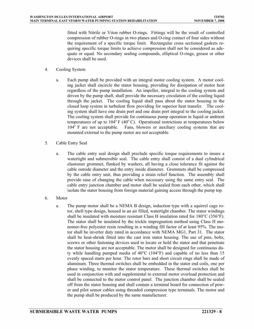
WASHINGTON DULLES INTERNATIONAL AIRPORT IT0702 MAIN TERMINAL EAST STORM WATER PUMPING STATION REHABILITATION NOVEMBER 7, 2008
fitted with Nitrile or Viton rubber O-rings. Fittings will be the result of controlled compression of rubber O-rings in two planes and O-ring contact of four sides without the requirement of a specific torque limit. Rectangular cross sectioned gaskets re-quiring specific torque limits to achieve compression shall not be considered as ade-quate or equal. No secondary sealing compounds, elliptical O-rings, grease or other devices shall be used.
4. Cooling System
a. Each pump shall be provided with an integral motor cooling system. A motor cool-ing jacket shall encircle the stator housing, providing for dissipation of motor heat regardless of the pump installation. An impeller, integral to the cooling system and driven by the pump shaft, shall provide the necessary circulation of the cooling liquid through the jacket. The cooling liquid shall pass about the stator housing in the closed loop system in turbulent flow providing for superior heat transfer. The cool-ing system shall have one drain port and one drain port integral to the cooling jacket. The cooling system shall provide for continuous pump operation in liquid or ambient temperatures of up to 104o F (40o C). Operational restrictions at temperatures below 104o F are not acceptable. Fans, blowers or auxiliary cooling systems that are mounted external to the pump motor are not acceptable.
5. Cable Entry Seal
a. The cable entry seal design shall preclude specific torque requirements to insure a watertight and submersible seal. The cable entry shall consist of a dual cylindrical elastomer grommet, flanked by washers, all having a close tolerance fit against the cable outside diameter and the entry inside diameter. Grommets shall be compressed by the cable entry unit, thus providing a strain relief function. The assembly shall provide ease of changing the cable when necessary using the same entry seal. The cable entry junction chamber and motor shall be sealed from each other, which shall isolate the stator housing from foreign material gaining access through the pump top.
6. Motor
a. The pump motor shall be a NEMA B design, induction type with a squirrel cage ro-tor, shell type design, housed in an air filled, watertight chamber. The stator windings shall be insulated with moisture resistant Class H insulation rated for 180°C (356°F). The stator shall be insulated by the trickle impregnation method using Class H mo-nomer-free polyester resin resulting in a winding fill factor of at least 95%. The mo-tor shall be inverter duty rated in accordance with NEMA MG1, Part 31. The stator shall be heat-shrink fitted into the cast iron stator housing. The use of pins, bolts, screws or other fastening devices used to locate or hold the stator and that penetrate the stator housing are not acceptable. The motor shall be designed for continuous du-ty while handling pumped media of 40°C (104°F) and capable of no less than 15 evenly spaced starts per hour. The rotor bars and short circuit rings shall be made of aluminum. Three thermal switches shall be embedded in the stator end coils, one per phase winding, to monitor the stator temperature. These thermal switches shall be used in conjunction with and supplemental to external motor overload protection and shall be connected to the motor control panel. The junction chamber shall be sealed off from the stator housing and shall contain a terminal board for connection of pow-er and pilot sensor cables using threaded compression type terminals. The motor and the pump shall be produced by the same manufacturer.
SUBMERSIBLE WASTE WATER PUMPS 221329 - 8

WASHINGTON DULLES INTERNATIONAL AIRPORT IT0702 MAIN TERMINAL EAST STORM WATER PUMPING STATION REHABILITATION NOVEMBER 7, 2008
b. The motor service factor (combined effect of voltage, frequency and specific gravity) shall be a minimum of 1.15. The motor shall have a voltage tolerance of plus or mi-nus 10%. The motor shall be designed for continuous operation up to 40°C (104°F) ambient and have a NEMA Class B maximum operating temperature rise of 80°C.
c. The power cable shall be sized according to the NEC and ICEA standards and shall be of sufficient length to reach the junction box without the need of any splices. The outer jacket of the cable shall be oil resistant chlorinated polyethylene rubber. The motor and cable shall be capable of continuous submergence underwater without loss of watertight integrity to a depth of 65 feet.
d. The motor horsepower shall be adequate so that the pump is non-overloading throughout the entire pump performance curve from shut-off through run-out.
7. Bearings
a. The integral pump/motor shaft shall rotate on two bearings. The motor bearings shall be sealed and permanently grease lubricated with high temperature grease. The up-per motor bearing shall be a two row angular contact ball bearing. The lower bearing shall be a two row angular contact ball bearing to handle the thrust and radial forces. The minimum L10 bearing life shall be 50,000 hours at any usable portion of the pump curve.
8. Mechanical Seal
a. Each pump shall be provided with a positively driven dual, tandem mechanical shaft seal system consisting of two seal sets, each having an independent spring. The low-er primary seal, located between the pump and seal chamber, shall contain one sta-tionary and one positively driven rotating corrosion resistant tungsten-carbide ring. The upper secondary seal, located between the seal chamber and the seal inspection chamber, shall contain one stationary and one positively driven rotating corrosion re-sistant tungsten-carbide ring. All seal rings shall be individually solid sintered rings. Each seal interface shall be held in place by its own spring system. The seals shall not depend upon direction of rotation for sealing. Mounting of the lower seal on the impeller hub will not be acceptable. Shaft seals without positively driven rotating members or conventional double mechanical seals containing either single or double spring acting between the upper and lower seal faces are not acceptable. The seal springs shall be isolated from the pumped media to prevent materials from packing around them, limiting their performance.
b. Each pump shall be provided with a lubricant chamber for the shaft sealing system. The lubricant chamber shall be designed to prevent overfilling and to provide lubri-cant expansion capacity. The seal lubricant chamber shall have one drain and one in-spection plug that are accessible from the exterior of the motor unit. The seal system shall not rely upon the pumped media for lubrication.
c. The exterior of the lower mechanical seal shall have an integral concentric spiral groove cast into the housing. This groove shall protect the seals by causing abrasive particulate entering the seal cavity to be forced out away from the seal due to cen-trifugal action.
SUBMERSIBLE WASTE WATER PUMPS 221329 - 9

WASHINGTON DULLES INTERNATIONAL AIRPORT IT0702 MAIN TERMINAL EAST STORM WATER PUMPING STATION REHABILITATION NOVEMBER 7, 2008
d. A separate seal leakage chamber shall be provided so that any leakage that may occur past the upper, secondary mechanical seal will be captured prior to entry into the mo-tor stator housing. Such seal leakage shall not contaminate the motor lower bearing. The leakage chamber shall be equipped with a float type switch that will signal if the chamber should reach 50% capacity.
e. Seal lubricant shall be FDA Approved, nontoxic.
9. Pump Shaft
a. Pump and motor shaft shall be a single piece unit. The pump shaft is an extension of the motor shaft. Couplings shall not be acceptable. The pump shaft shall be stainless steel, ASTM A479 S43100-T.
10. Impeller
a. The impeller shall be of gray cast iron, ASTM A 48 Class 35B, dynamically bal-anced, semi-open, multi-vane, back-swept, screw shaped, non-clog design. The im-peller leading edges shall be mechanically self-cleaned upon each rotation as they pass across a spiral groove located on the volute suction. The screw-shaped leading edges of the impeller shall be hardened to Rc 45 and shall be capable of handling sol-ids, fibrous materials, heavy sludge and other matter found in waste water. The screw shape of the impeller inlet shall provide an inducing effect for the handling of 6 % sludge and rag-laden waste water. The impeller to volute clearance shall be readily adjustable by the means of a single trim screw. Impellers shall be locked to the shaft and held by an impeller bolt.
11. Volute/Suction Cover
a. The pump volute shall be of ASTM A 48, Class 35B non-concentric design with smooth passages of sufficient size to pass any solids that may enter the impeller. The volute shall have a replaceable volute insert ring containing spiral-shaped, sharp-edged grooves. The spiral grooves shall provide the relief path and sharp edges across which each impeller vane leading edge shall cross during rotation so to remain unobstructed. The internal volute bottom shall provide effective sealing between the multi-vane semi-open impeller and the volute. The insert ring shall be cast of ASTM A 48, Class 35B cast iron.
12. Protection
a. Pump motor stator shall incorporate three thermal switches, one per stator phase winding and be connected in series to monitor the temperature of the motor. Should the thermal switches open the motor shall stop and activate an alarm back to the pump control panel. A float switch shall be installed in the seal leakage chamber and should activate if leakage into the chamber reaches 50% chamber capacity, signaling the need to schedule an inspection
b. The thermal switches and float switch shall be connected to a Control and Status Monitoring Unit. The Control and Status Monitoring Unit shall be designed to be mounted within the pump control panel.
SUBMERSIBLE WASTE WATER PUMPS 221329 - 10

WASHINGTON DULLES INTERNATIONAL AIRPORT IT0702 MAIN TERMINAL EAST STORM WATER PUMPING STATION REHABILITATION NOVEMBER 7, 2008
13. Data Plates, Hardware and Lifting Cables
a. Data plates: All data plates shall be of stainless steel or brass, suitably attached to each pump. Data plates shall contain the manufacturer’s name, pump size and type, serial number, speed, impeller diameter, capacity and head rating and other pertinent data. A special data plate shall be attached to the pump frame, which shall contain identification of frame and bearing numbers.
b. Hardware: All machine bolts, nuts and cap screws shall be stainless steel and of the hex head type. Hardware or parts requiring special tools or wrenches shall not be used.
14. Balance and Vibration
a. Balance and vibration shall meet NEMA Standards MG1-12.05 and B\MG1-12.06.
2.2 QUADRIPLEX SUBMERSIBLE WASTE WATER PUMP CONTROL PANEL
A. General
1. Contractor shall furnish all labor, materials, equipment and incidentals required to provide a quadriplex motor control panel.
2. Motor control panel shall be assembled and tested by a shop meeting U.L. Standard 508 for industrial controls. The motor control panel shall be assembled and tested by the same manufacturer supplying the pumps so as to insure suitability and assurance of experience in matching controls to motors and to insure single source responsibility for the equipment.
3. Waste water pump control panel shall be sized to fit within the aboveground 72” wide x 24” deep x 84” high Electrical Equipment Enclosure while maintaining adequate space for the remainder of the items specified to be installed in the enclosure as shown on drawings.
.
B. Construction
1. The controls for the pumps shall be contained in a floor mounted stainless steel enclosure meeting NEMA 3R requirements with hinged doors. A phenolic plate with 1/2 inch high white lettering, cut through a black background shall be provided on the face of the control panel to identify the pump being controlled.
2. The enclosure shall have provisions for padlocking. A nameplate shall be permanently af-fixed to the panel and include the pump model numbers, voltage, phase, hertz, ampere rat-ings and horsepower ratings. A warning label against electric shock shall be permanently affixed to the outer doors. The outer doors shall be attached to the enclosure using cap-tured, quarter turn stainless steel screws and a continuous type piano hinge. A hinge ar-rangement, which requires unbolting for removal of the outer door, is not acceptable.
SUBMERSIBLE WASTE WATER PUMPS 221329 - 11

WASHINGTON DULLES INTERNATIONAL AIRPORT IT0702 MAIN TERMINAL EAST STORM WATER PUMPING STATION REHABILITATION NOVEMBER 7, 2008
3. For each pump a red run light, green stop/off light, amber heat sensor shut-down light, am-ber seal failure light and a hand-off-auto switch shall be provided. Lights and hand-off-auto switches shall be bracket mounted. The lights and hand-off-auto switches shall be properly labeled with phenolic plates with 1/4 inch high white lettering, cut through a black background identifying the function for the switch or light.
4. Hand-off-auto (HOA) switches for Waste Water Pumps No. 1 or 2 when indexed to the hand position shall lock out Waste Water Pumps No. 3 and 4. Similarly if an HOA switch for Waste Water Pumps No. 3 or 4 is indexed to the hand position Waste Water Pumps No. 1 and 2 shall be locked out. Provide phenolic plates with 1/4 inch high white lettering, cut through a red background identifying that Pumps No. 1 and 2 will not run if Pump No. 3 or 4 are in the hand position and vice versa. Phenolic nameplate shall be mounted on the face of the panel above the HOA switches.
5. Panel shall contain a programmable logic controller (PLC) programmed and wired to oper-ate the pumps based on the level inputs from the output contacts on the liquid level control-ler to provide the sequence of operation identified in Paragraph 3.2.E. PLC shall be Sie-mens-Milltronics HydroRanger 200 (Refer to Specification Section 221329, Paragraph 2.4) PLC Outputs shall be rated to properly operate the motor starter contacts. If required an in-terposing relay shall be provided. PLC logic shall be submitted as part of approval draw-ings. PLC shall be rated for a temperature range between -4º to + 122ºF and 95% relative humidity.
6. The incoming power feed shall be single source 460 volts, 3 phase, 60 hertz, protected by lightning arrestor. Terminal blocks with box type lugs shall be supplied to terminate all wiring for liquid level controls and heat and seal sensors for each pump. The pump leads shall be terminated at the overload relay or at box type terminal blocks.
7. A circuit breaker shall be used to protect from line faults and to disconnect all four pumps from incoming power. In addition, circuit breaker shall be provided to protect from line faults and to disconnect each individual pump from incoming power. Circuit breakers shall be thermal magnetic and sized to meet NEC requirements for motor controls.
8. An across-the-line type starter shall be provided for each pump within the control panel. Refer to Section 221329, Paragraph 2.3.
9. Control voltage shall be 120 VAC and shall be accomplished by the means of a trans-former. A control fuse and on/off switch shall protect and isolate the control voltage from the line.
10. Wire ties shall be used to maintain panel wiring in neat bundles for maintenance and to prevent interference with operating devices. All wiring shall be color-coded to facilitate maintenance and repair of the control panel. Where a color is repeated, number coding shall be added. An approved schematic shall be permanently attached to the inside surface of the front door.
11. All ground connections shall be made with ring tongue terminals and star washers to assure proper ground.
12. Panel shall contain the necessary logic for connecting heat sensor monitors and seal failure probe/relays to box type lug connectors.
SUBMERSIBLE WASTE WATER PUMPS 221329 - 12

WASHINGTON DULLES INTERNATIONAL AIRPORT IT0702 MAIN TERMINAL EAST STORM WATER PUMPING STATION REHABILITATION NOVEMBER 7, 2008
13. Box type lug connectors shall be made of polyamide thermoplastic to exclude aging due to heat influences.
14. The pump controller is specified in Section 221329 - Liquid Level Controls, Paragraph 2.4.C.
C. Options
1. Panel shall be equipped with the following additional features.
a. Dry contacts for telemetry of alarm conditions listed below in addition to three (3) sets for future alarm points.
b. Heat sensor - manual reset. c. 110-volt terminal blocks for secondary backup float system power interconnection.
2. Communications/Remote Alarm Circuit: Include communications equipment in waste wa-ter pump control panel for connection to Authority’s EMCS System integrator remote alarm panel in West Utility Building. Contractor shall be responsible to extend existing wiring and conduit from existing pumping station to new waste water pump control panel. Coordinate with Authority’s EMCS System integrator (Siemens). Contact Siemens repre-sentative George Coyle at (301) 837-2574; Fax (301) 206-2141.
a. Loss of incoming power to waste water pump control panel: This shall be accom-plished by monitor the three phase power and 120 volt control power for one com-mon alarm output as dry contacts.
b. Pump Failure Alarm: This shall be accomplished using adjustable low current moni-tor relays with current transformers if required on the load output wiring to each waste water pump. Relays and current transformers shall be installed between the waste water pump circuit breaker and pump motor starter. The relays shall indicate pump failure to run condition and shall activate an alarm signal. All four pump alarm contacts shall be wired in parallel for one output alarm to the Authority’s EMCS Sys-tem.
The low current monitor relay will monitor the pump motor current once it has been
called to run. Relays shall have a time delay setting to allow the motor current to reach normal full load current before the low current function is monitored. If the pump fails by low running current the pump will be locked out until manually reset by a common reset push button.
c. High Water Level Alarm (Secondary backup float system).
2.3 SUBMERSIBLE WASTE WATER PUMP MOTOR STARTERS
A. Motor starters for Submersible Waste Water Pumps No. 1, 2, 3 and 4 shall be furnished by the same manufacturer as the pumps.
B. Motor starter shall be across-the-line type with the following components.
1. Full voltage starter, magnetic non-reversing type. Starters for Waste Water Pumps No. 1 and 2 shall be capable of fifteen (15) starts per hour on a continuous 24-hour basis in a 40
SUBMERSIBLE WASTE WATER PUMPS 221329 - 13

WASHINGTON DULLES INTERNATIONAL AIRPORT IT0702 MAIN TERMINAL EAST STORM WATER PUMPING STATION REHABILITATION NOVEMBER 7, 2008
degrees Celsius ambient temperature. Starters for Waste Water Pumps No. 3 and 4 shall be capable of thirty (30) starts per hour on a continuous 24-hour basis in a 40 degrees Celsius ambient temperature. The starter manufacturer shall certify and guarantee that the starter provided, as described below is capable of operating on the duty cycle basis previously stated. Starters shall be equipped and wired with the following:
a. Three pole starting contactors with auxiliary relays and interlocks. b. Door mounted manual overload reset button. c. Fused control transformer rated at 460/120 volts. d. Manual-off-auto selector switch with knurled handle. Door mounted. e. Terminal block for external wiring connections. f. Elapsed time meter, with no reset and range of 99999.9 hours. It shall be numbered
wheel type. The numbers shall have minimum height of 3/16". The meter shall be door mounted.
g. Starter shall be completely wired internally by the manufacturer.
2.4 LIQUID LEVEL CONTROL AND ALARM SYSTEM
A. Primary control system for Submersible Waste Water Pumps No. 1, 2, 3 and 4 shall consist of an ultrasonic level transducer, six (6) relay Milltronics HydroRanger 200 programmable controller with 120 volts power supply and Hand Programmer to set up the programmable controller. Sys-tem shall be as manufactured by Siemens.
B. The programmable controller and relays shall be factory installed in a wall mounted polycarbon-ate, NEMA 4X enclosure.
C. Ultrasonic transducer shall be Siemens Echomax XRS-5 complete with stainless steel mounting bracket. Transducer housing shall be capable of being fully submerged and have a chemically re-sistant PVDF copolymer enclosure and CSM rubber face
1. Measuring Range 0.3 to 8.0 Meters (1 to 26 Feet). 2. Output frequency: 44 kHz 3. Output Beam Angle: 10 Degrees. 4. Ambient Temperature Range: -4º to + 149ºF 5. Cable/Cable Length: 2-core twisted pair, foil shield, 20 AWG, PVC sheath / Minimum ca-
ble length 30 Feet.
D. Programmable Controller shall be Siemens HydroRanger 200, capable of single point monitoring and be provided with four (4) SPST Form A and Two (2) SPDT Form C and be UL Listed.
1. Relay Ratings: 5A at 250 V AC, non-inductive. 2. Measurement Accuracy: 0.25%. 3. Resolution Accuracy: 0.1%. 4. Temperature Compensation Range: -58º to +302ºF 5. Display and Controls: Multi-block LCD with backlighting.
6. Power Supply: 100 to 230 V AC + 15%, 50/60 Hz, Maximum 36 VA. 7. Maximum allowable separation between the transducer and controller: 1,200 Feet.
E. Liquid level control system shall include a high water alarm notification system. High water alarm shall consist of a weatherproof flashing red light and horn with silence button with auto-
SUBMERSIBLE WASTE WATER PUMPS 221329 - 14

WASHINGTON DULLES INTERNATIONAL AIRPORT IT0702 MAIN TERMINAL EAST STORM WATER PUMPING STATION REHABILITATION NOVEMBER 7, 2008
matic reset. The light and horn shall be installed on the exterior of the Electrical Equipment Cab-inet at grade level approximately twelve (12) inches above the top of the cabinet in a NEMA 4X stainless steel enclosure. Silence button shall be located on the face of the waste water pump con-trol panel. The alarm shall be activated by the HydroRanger 200 or by the secondary backup high level float.
1. Horn Rating: 82 Decibels at 10 Feet. 2. Dry contacts (2 sets) for telemetry of alarm conditions. One set will be for future use and
one set will be used to send the Secondary backup float system High Water Level Alarm signal to Authority’s EMCS System.
3. Terminal block (115 volt) for remote mounted liquid level controller power interconnec-tion.
F. A secondary backup float system consisting of a high level alarm float, high level float and a low level float shall be provided. The high level and low level floats shall start and stop Submersible Waste Water Pumps No. 3 and 4 in the event the primary liquid level control system failure. Float switches shall be intrinsically safe. Should the high level float be activated the level sensor shall be disabled and only restored via a reset button mounted on the face of the panel. The back-up float system shall also contain a dedicated float switch to actuate the high water alarm horn and light. All features of the backup float system including the alarm horn and light shall be reset using a panel mounted reset button.
2.5 WET WELL ACCESS DOORS
A. Manufacturers: subject to compliance with requirements, available manufacturers offering prod-ucts that may be incorporated into the Work include, but are not limited to, the following:
1. Acudor Products, Inc. 2. Syracuse Castings, Inc. 3. USF Fabrications, Inc. 4. Williams Brothers Corporation of America
B. Description: Access cover shall be aluminum construction, double leaf custom metal fabrication with support system designed to fit within existing circular concrete wet-well floor openings. Access cover design shall be a field-assembled, sectional design to allow for installation of access cover in underground pumping station vault. Floor cover may be round or square and be pro-vided with circular sleeved openings to accommodate pump discharge piping as indicated on drawings. Access cover doors shall be sized to allow for pump removal without disassembling cover or cover support framing. Cover support framing and access openings shall provide a min-imum clearance of two (2) inches between pumps and cover construction to allow for pump re-moval, via the rail removal system, without rotating or manipulating the orientation of the pump.
1. Cover and Doors: aluminum diamond pattern plate (¼ inch thick) reinforced for 300 pounds per square foot live load, with a maximum projection of ¼ above floor to top of cover. Doors shall be equipped with flush mounted cast aluminum flush lifting handle.
2. Opening Device: Automatic hold-open arm with red vinyl grip allowing door panels to open to 90 degrees, locking door in open position, and allowing for easy control when clos-ing door panels. Stainless steel compression springs and lift assistance.
3. Cover Supports: Aluminum extrusions.
4. Access Door Hinges: Stainless steel hinges and hinge pins.
SUBMERSIBLE WASTE WATER PUMPS 221329 - 15
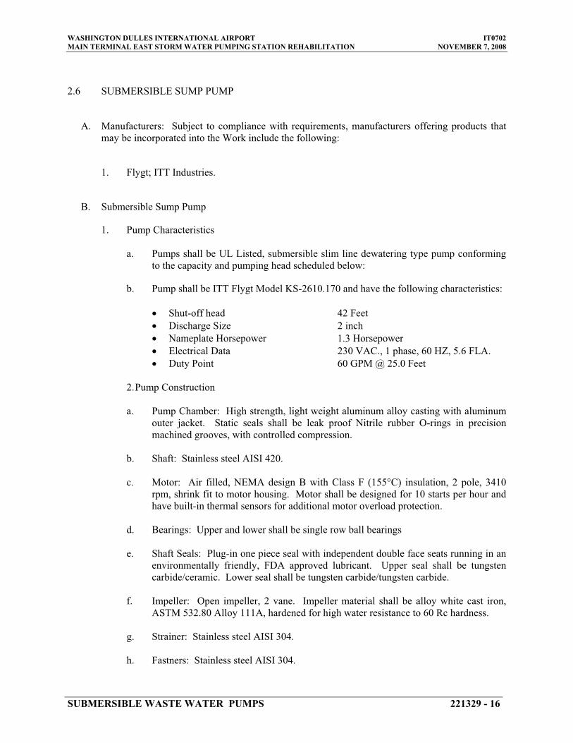
WASHINGTON DULLES INTERNATIONAL AIRPORT IT0702 MAIN TERMINAL EAST STORM WATER PUMPING STATION REHABILITATION NOVEMBER 7, 2008
2.6 SUBMERSIBLE SUMP PUMP
A. Manufacturers: Subject to compliance with requirements, manufacturers offering products that may be incorporated into the Work include the following:
1. Flygt; ITT Industries.
B. Submersible Sump Pump
1. Pump Characteristics
a. Pumps shall be UL Listed, submersible slim line dewatering type pump conforming to the capacity and pumping head scheduled below:
b. Pump shall be ITT Flygt Model KS-2610.170 and have the following characteristics:
� Shut-off head 42 Feet � Discharge Size 2 inch � Nameplate Horsepower 1.3 Horsepower � Electrical Data 230 VAC., 1 phase, 60 HZ, 5.6 FLA. � Duty Point 60 GPM @ 25.0 Feet
2. Pump Construction
a. Pump Chamber: High strength, light weight aluminum alloy casting with aluminum outer jacket. Static seals shall be leak proof Nitrile rubber O-rings in precision machined grooves, with controlled compression.
b. Shaft: Stainless steel AISI 420.
c. Motor: Air filled, NEMA design B with Class F (155°C) insulation, 2 pole, 3410 rpm, shrink fit to motor housing. Motor shall be designed for 10 starts per hour and have built-in thermal sensors for additional motor overload protection.
d. Bearings: Upper and lower shall be single row ball bearings
e. Shaft Seals: Plug-in one piece seal with independent double face seats running in an environmentally friendly, FDA approved lubricant. Upper seal shall be tungsten carbide/ceramic. Lower seal shall be tungsten carbide/tungsten carbide.
f. Impeller: Open impeller, 2 vane. Impeller material shall be alloy white cast iron, ASTM 532.80 Alloy 111A, hardened for high water resistance to 60 Rc hardness.
g. Strainer: Stainless steel AISI 304.
h. Fastners: Stainless steel AISI 304.
SUBMERSIBLE WASTE WATER PUMPS 221329 - 16

WASHINGTON DULLES INTERNATIONAL AIRPORT IT0702 MAIN TERMINAL EAST STORM WATER PUMPING STATION REHABILITATION NOVEMBER 7, 2008
2.7 TEMPORARY BYPASS WASTE WATER PUMPING SYSTEM
A. Refer to Specification Section 221329, Paragraph 3.4.
PART 3 - EXECUTION
3.1 GENERAL
A. Existing underground storm water pumping station structure shall be reused in new work.
B. Prior to performing any work within the storm water pumping station the contractor shall provide each of his employees that will be working in the underground structure with breathing apparatus and protective clothing suitable for the application in compliance with OSHA Standards.
C. The existing pumping station is provided with rung type ladders as shown on contract drawings. Contractor shall be responsible to provide scaffolding and/or work platforms and supports neces-sary to perform the work of this project. At the completion of the work all scaffolding, work, platforms and supports shall be removed. Any surfaces damaged by installation of scaffolding or work platforms shall be repaired to match adjacent surfaces.
3.2 SUBMERSIBLE PUMPS
A. The Contractor shall be responsible for the complete installation of the submersible waste water pumping system including base plates; liquid level controls; all adjustments; lubrication and ser-vicing; start-up and test operation.
B. Installation and start-up of the new waste water pumps and associated equipment shall be in ac-cordance with the pump manufacturers printed instructions. Work operations shall be in accor-dance with Construction Phasing Schedule approved by the Engineer. Refer to Paragraph 3.3 of this section for Construction Phasing Schedule.
C. Mount pump control panel and liquid level controller in equipment enclosures provided at grade level and perform electrical connections for the new waste water pumps. Refer to Specification Section 262816 for Electrical Equipment Enclosures.
D. Mount liquid level ultrasonic transducers and back-up float-Switch system in pumping station wet well and perform electrical connections for the new waste water pumps.
E. HydroRanger 200 Level Control Operation
1. The Mechanical Contractor shall provide all level controls and equipment for the new waste water pumps and make all wiring connections to the level control equipment. Pump-ing stations shall operate as follows:
a. When the water level rises to the Submersible Pump No.1 “Pump On” level, the lead pump will start.
b. When the water level is lowered to the “Pump Off”, the lead pump will stop.
SUBMERSIBLE WASTE WATER PUMPS 221329 - 17

WASHINGTON DULLES INTERNATIONAL AIRPORT IT0702 MAIN TERMINAL EAST STORM WATER PUMPING STATION REHABILITATION NOVEMBER 7, 2008
c. The alternator will then make the above pump the “Lag” pump, and the Submersible Pump No. 2 will then become the lead pump.
d. If the water level continues to rise and reaches Submersible Pump No. 3 “On Level”, the pump will start and Submersible Pumps No. 1 and 2 shall be locked out.
e. When the water level is lowered to the “Pump Off”, Submersible Pump No. 3 will stop.
f. If the water level continues to rise and reaches Submersible Pump No. 4 “On Level”, the pump will start.
g. The alternator will then make submersible Pump No. 3 “Lag” pump, and the Sub-mersible Pump No. 4 will then become the lead pump.
h. If the water level continues to rise and reaches the “Alarm Level” the high water alarm will engage.
i. When the water level drops below the liquid level of Submersible pumps No. 3 and 4 the pumps shall be de-energized and the sequence described in Subparagraphs a , b and c above shall occur.
F. Secondary Backup Float Level Control Operation
1. The Mechanical Contractor shall provide all level controls and equipment and make all wir-ing connections to the level control equipment. Pumping stations shall operate as follows:
a. In the event a malfunction occurs with the HydroRanger 200 liquid level control sys-tem and the water level within the sump pump reaches the secondary high water “Alarm Level” the high water notification system will be engaged and send an alarm to the Authority’s EMCS System. Refer to Paragraphs 2.2.C and 2.4.E.
b. When the water level rises to the secondary float “Pump On” level, Pumps No. 3 and 4 will start. Pumps No. 1 and 2 shall be locked out.
c. When the water level is lowered to the secondary float “Pump Off” level, Pumps No. 3 and 4 will stop.
d. When the HydroRanger 200 liquid level control system malfunction is corrected a re-set button shall deactivate the secondary backup float level control system returning pumping system control to the HydroRanger 200 control system.
3.3 WASTE WATER EJECTOR PUMP CONSTRUCTION SCHEDULE
A. Prior to demolition of existing waste water pumps, the Contractor shall prepare a project con-struction sequence outlining demolition and rehabilitation work. Sequence shall be reviewed and approved by the Authority prior to commencement of work. After suitable coordination and ap-proval is obtained from the Authority the work may proceed.
B. Project Construction Sequence shall meet the following criteria:
1. During the construction period, the existing storm water pumping station must remain op-erational at all times.
2. Contractor shall provide temporary waste water pumps. Pumps shall be located within the sediment chamber of the East Pumping Station. Weep holes located in the baffle wall sepa-rating the sediment chamber from the wet well shall be temporarily sealed and made water-tight. Temporary pumps shall have adequate capacity, to handle the influent flow into the
SUBMERSIBLE WASTE WATER PUMPS 221329 - 18

WASHINGTON DULLES INTERNATIONAL AIRPORT IT0702 MAIN TERMINAL EAST STORM WATER PUMPING STATION REHABILITATION NOVEMBER 7, 2008
pumping station and include all controls and piping. Refer to Paragraph 3.4 of this Section. Piping for temporary system shall be installed from the existing pumping station and dis-charge into existing Storm Water Manhole D503. Refer to Drawing GN01.02 for manhole location. Once temporary pumping system is operational, temporary pipe plugs (test plug) shall be installed in the ten inch forced main from the pumping station with Storm Water Manhole D503 to insure storm water does not flow back into the existing East Storm Water Pumping Station. Provide temporary barricades, protective measures for open manhole and temporary pumping.
3. Contractor shall provide necessary pipe anchors to prevent movement of temporary dis-charge piping.
4. After new waste water pumps, valves and discharge piping are installed, contractor shall remove the temporary waste water pumps and discharge piping.
3.4 TEMPORARY BYPASS WASTE WATER PUMPING SYSTEM
A. Temporary Waste Water Pumping Work Scope
1. The Contractor is required to furnish all materials, labor, equipment, power, maintenance, etc. to implement a temporary pumping system for the purpose of diverting the existing flow around the work area for the duration of the project.
2. The design, installation and operation of the temporary pumping system shall be the Con-tractor’s responsibility. The Contractor shall employ the services of a Vendor who can demonstrate to the Authority that he specializes in the design and operation of temporary bypass pumping systems. The Vendor shall provide at least five (5) project references of a similar size and complexity of this project, performed by his firm within the past three years. The bypass system shall meet the requirements of all codes and regulatory agencies having jurisdiction.
3. The Contractor shall submit to the Authority detailed plans and descriptions outlining all provisions and precautions to be taken by the Contractor regarding the handling of waste water flow. This plan must be specific and complete, including such items as schedules, lo-cations, elevations, capacities of equipment, materials and all other incidental items neces-sary and/or required to insure proper protection of the facilities, including protection of the access and bypass pumping locations from damage due to the discharge flows, and compli-ance with the requirements and permit conditions specified in these Contract Documents. No construction shall begin until all provisions and requirements have been reviewed and approved by the Authority.
4. The plan shall include but not limited to details of the following:
a. Staging areas for pumps; b. Storm water sewer plugging method and types of plugs to be used. c. Number, size, material, location and method of installation of suction piping; d. Number, size, material, method of installation and location of installation of dis-
charge piping; e. Bypass pump sizes, capacity, quantity of each pump size to be on site and power re-
quirements;
SUBMERSIBLE WASTE WATER PUMPS 221329 - 19

WASHINGTON DULLES INTERNATIONAL AIRPORT IT0702 MAIN TERMINAL EAST STORM WATER PUMPING STATION REHABILITATION NOVEMBER 7, 2008
f. Calculations of static lift, friction losses, and flow velocity (pump curves showing pump operating range shall be submitted).
g. Standby power generator size, location; h. Downstream discharge plan. i. Method of protecting discharge manholes or structures from erosion and damage. j. Thrust and restraint block sizes and locations. k. Method of noise control for each pump and/or generator. l. Any temporary pipe supports and anchoring required. m. Design plans and computation for access to bypass pumping locations. n. Calculations for selection of bypass pumping pipe size. o. Schedule for installation of and maintenance of bypass pumping lines. p. Plan indicating selected location for bypass pumping and discharge line location.
B. Equipment
1. All pumps used shall be fully automatic self-priming units that do not require the use of foot valves or vacuum pumps in the priming system. The pumps shall be electric powered as described on drawings. All pumps used must be constructed to allow dry running for long periods of time to accommodate the cyclical nature of effluent flows.
2. The Contractor shall provide the necessary stop/start controls for each pump.
3. The Contractor shall include one stand-by pump of each size to be maintained on site. Back-up pumps shall be on-line, isolated from the primary system by a valve.
4. Discharge Piping: In order to prevent the accidental spillage of flows all discharge systems shall be temporarily constructed of rigid pipe with positive, restrained joints. Under no cir-cumstances will aluminum “irrigation” type piping or glued PVC pipe be allowed. Dis-charge hose will only be allowed in short sections and by specific permission from the Au-thority.
C. System Description
1. Design Requirements:
a. Flow capacity of bypass pumping systems shall match the capacity of the new pump-ing system. The Contractor shall provide all pipeline plugs, pumps of adequate size to handle peak flow, and temporary discharge piping to ensure that the total flow of the main can be safely diverted around the section to be repaired. Bypass pumping system will be required to be operated 24 hours per day.
b. The Contractor shall have adequate standby equipment available and ready for im-mediate operation and use in the event of an emergency or breakdown. One standby pump for each size pump utilized shall be installed at bypassing locations, ready for use in the event of primary pump failure.
c. Bypass pumping system shall be capable of bypassing the flow around the work area as necessary for satisfactory performances of work.
d. The Contractor shall make all arrangements for bypass pumping during the time when the main is shut down for any reason. System must overcome any existing main pressure on discharge.
SUBMERSIBLE WASTE WATER PUMPS 221329 - 20

WASHINGTON DULLES INTERNATIONAL AIRPORT IT0702 MAIN TERMINAL EAST STORM WATER PUMPING STATION REHABILITATION NOVEMBER 7, 2008
2. Performance Requirements:
a. It is essential to the operation of the existing storm water system that there are no in-terruptions in the flow of storm water throughout the duration of the project. To this end, the Contractor shall provide, maintain and operate all temporary facilities such as dams, plugs, pumping equipment (both primary and back-up units as required), conduits, all necessary power, and all other labor and equipment necessary to inter-cept the waste water flow before it reaches the point where it would interfere with his work, carry it past his work and return it to the existing storm water sewer down-stream of his work.
b. The design, installation and operation of the temporary pumping system shall be the Contractor's responsibility. The bypass system shall meet the requirements of all codes and regulatory agencies having jurisdiction.
c. The Contractor shall provide all necessary means to safely convey the waste water past the work area. The Contractor will not be permitted to stop or impede the main flows under any circumstances.
d. The Contractor shall maintain waste water flow around the work area in a manner that will not cause surcharging of sewers or damage to sewers and that will protect airport property from damage and flooding.
D. Field Quality Control and Maintenance
1. Test:
a. The Contractor shall perform leakage and pressure tests of the bypass pumping dis-charge piping using clean water prior to actual operation. The Authority shall be giv-en 24 hours notice prior to testing.
2. Inspection:
a. Contractor shall inspect bypass pumping system every four hours to ensure that the system is working correctly.
3. Maintenance Service:
a. The Contractor shall insure that the temporary pumping system is properly main-tained and a responsible operator shall be on hand at all times when pumps are oper-ating.
4. Extra Materials:
a. Spare parts for pumps and piping shall be kept on site as required.
b. Adequate hoisting equipment for each pump and accessories shall be maintained on the site.
E. Preparation
1. Contractor is responsible for locating any existing utilities in the area the Contractor selects
SUBMERSIBLE WASTE WATER PUMPS 221329 - 21
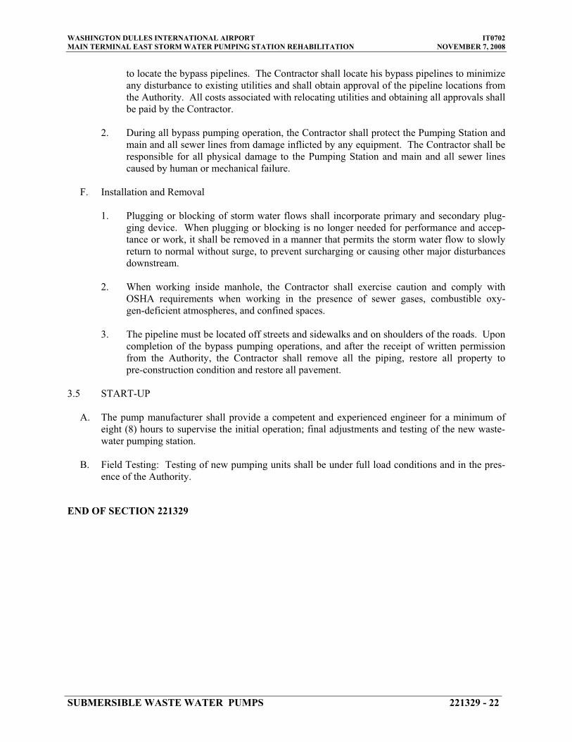
WASHINGTON DULLES INTERNATIONAL AIRPORT IT0702 MAIN TERMINAL EAST STORM WATER PUMPING STATION REHABILITATION NOVEMBER 7, 2008
to locate the bypass pipelines. The Contractor shall locate his bypass pipelines to minimize any disturbance to existing utilities and shall obtain approval of the pipeline locations from the Authority. All costs associated with relocating utilities and obtaining all approvals shall be paid by the Contractor.
2. During all bypass pumping operation, the Contractor shall protect the Pumping Station and main and all sewer lines from damage inflicted by any equipment. The Contractor shall be responsible for all physical damage to the Pumping Station and main and all sewer lines caused by human or mechanical failure.
F. Installation and Removal
1. Plugging or blocking of storm water flows shall incorporate primary and secondary plug-ging device. When plugging or blocking is no longer needed for performance and accep-tance or work, it shall be removed in a manner that permits the storm water flow to slowly return to normal without surge, to prevent surcharging or causing other major disturbances downstream.
2. When working inside manhole, the Contractor shall exercise caution and comply with OSHA requirements when working in the presence of sewer gases, combustible oxy-gen-deficient atmospheres, and confined spaces.
3. The pipeline must be located off streets and sidewalks and on shoulders of the roads. Upon completion of the bypass pumping operations, and after the receipt of written permission from the Authority, the Contractor shall remove all the piping, restore all property to pre-construction condition and restore all pavement.
3.5 START-UP
A. The pump manufacturer shall provide a competent and experienced engineer for a minimum of eight (8) hours to supervise the initial operation; final adjustments and testing of the new waste-water pumping station.
B. Field Testing: Testing of new pumping units shall be under full load conditions and in the pres-ence of the Authority.
END OF SECTION 221329
SUBMERSIBLE WASTE WATER PUMPS 221329 - 22

WASHINGTON DULLES INTERNATIONAL AIRPORT IT0702 MAIN TERMINAL EAST STORM WATER PUMPING STATION REHABILITATION NOVEMBER 7, 2008
SECTION 221413 – STORM WATER DRAINAGE PIPING
PART 1 - GENERAL
1.1 RELATED DOCUMENTS
A. Drawings and general provisions of the Contract, including General and Supplementary Conditions and Division 01 Specification Sections, apply to this Section.
1.2 SUMMARY
A. This Section includes the following storm drainage piping inside the building:
1. Pipe and fittings.
1.3 PERFORMANCE REQUIREMENTS
A. Components and installation shall be capable of withstanding a minimum working-pressure of 100 psig, unless otherwise indicated:
1.4 SUBMITTALS
A. Product Data: For pipe and fittings.
B. Field quality-control inspection and test reports.
1.5 QUALITY ASSURANCE
A. Provide listing approval stamp, label or other markings on pipe made to specified standard. Piping materials shall bear label, stamp, or other markings of specified testing agency.
PART 2 - PRODUCTS
2.1 PIPING MATERIALS
A. Acceptable Manufacturers:
Subject to compliance with requirements, provide products of the following manufacturer:
STORM WATER DRAINAGE PIPING 221413 - 1
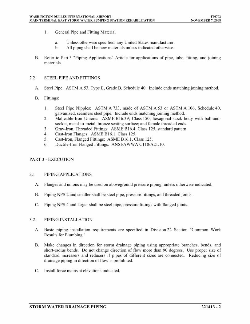
WASHINGTON DULLES INTERNATIONAL AIRPORT IT0702 MAIN TERMINAL EAST STORM WATER PUMPING STATION REHABILITATION NOVEMBER 7, 2008
1. General Pipe and Fitting Material
a. Unless otherwise specified, any United States manufacturer. b. All pipng shall be new materials unless indicated otherwise.
B. Refer to Part 3 "Piping Applications" Article for applications of pipe, tube, fitting, and joining materials.
2.2 STEEL PIPE AND FITTINGS
A. Steel Pipe: ASTM A 53, Type E, Grade B, Schedule 40. Include ends matching joining method.
B. Fittings:
1. Steel Pipe Nipples: ASTM A 733, made of ASTM A 53 or ASTM A 106, Schedule 40, galvanized, seamless steel pipe. Include ends matching joining method.
2. Malleable-Iron Unions: ASME B16.39; Class 150; hexagonal-stock body with ball-and-socket, metal-to-metal, bronze seating surface; and female threaded ends.
3. Gray-Iron, Threaded Fittings: ASME B16.4, Class 125, standard pattern. 4. Cast-Iron Flanges: ASME B16.1, Class 125. 5. Cast-Iron, Flanged Fittings: ASME B16.1, Class 125. 6. Ductile-Iron Flanged Fittings: ANSI/AWWA C110/A21.10.
PART 3 - EXECUTION
3.1 PIPING APPLICATIONS
A. Flanges and unions may be used on aboveground pressure piping, unless otherwise indicated.
B. Piping NPS 2 and smaller shall be steel pipe, pressure fittings, and threaded joints.
C. Piping NPS 4 and larger shall be steel pipe, pressure fittings with flanged joints.
3.2 PIPING INSTALLATION
A. Basic piping installation requirements are specified in Division 22 Section "Common Work Results for Plumbing."
B. Make changes in direction for storm drainage piping using appropriate branches, bends, and short-radius bends. Do not change direction of flow more than 90 degrees. Use proper size of standard increasers and reducers if pipes of different sizes are connected. Reducing size of drainage piping in direction of flow is prohibited.
C. Install force mains at elevations indicated.
STORM WATER DRAINAGE PIPING 221413 - 2

WASHINGTON DULLES INTERNATIONAL AIRPORT IT0702 MAIN TERMINAL EAST STORM WATER PUMPING STATION REHABILITATION NOVEMBER 7, 2008
3.3 JOINT CONSTRUCTION
A. Basic piping joint construction requirements are specified in Division 22 Section "Common Work Results for Plumbing."
3.4 VALVE INSTALLATION
A. General valve installation requirements are specified in Division 22 Section "Valves."
B. Shutoff Valves: Install shutoff valve on each sump pump discharge.
1. Install gate valve for piping NPS 2 and larger.
C. Check Valves: Install check valve, between pump and shutoff valve, on each waste water pump discharge.
3.5 HANGER AND SUPPORT INSTALLATION
A. Pipe hangers and supports are specified in Division 22 Section "Hangers and Supports for Piping and Equipment." Install the following:
1. Vertical Piping: MSS Type 8 or Type 42, clamps. 2. Individual, Straight, Horizontal Piping Runs: According to the following:
a. MSS Type 1, adjustable, steel clevis hangers.
B. Install supports according to Division 22 Section "Hangers and Supports for Piping and Equipment."
3.6 FLANGES, GASKETS AND BOLTS
A. All flanges shall be raised face, drilled for 125 psi working pressure.
B. Gaskets shall be non-asbestos compressed synthetic fiber, SBR binder, factory cut and punched suitable for its intended service application.
C. Bolts and nuts for flanged joints shall be carbon steel hexagon head machine bolts with heavy semi-finished hexagon nuts.
3.7 CONNECTIONS
A. Drawings indicate general arrangement of piping, fittings, and specialties.
B. Connect storm water drainage piping to exterior storm drainage piping. Use transition fitting to join dissimilar piping materials.
C. Connect storm drainage piping from waste water pumps amd sump pump to storm water header located within storm water pumping station as indicated on drawings.
STORM WATER DRAINAGE PIPING 221413 - 3

WASHINGTON DULLES INTERNATIONAL AIRPORT IT0702 MAIN TERMINAL EAST STORM WATER PUMPING STATION REHABILITATION NOVEMBER 7, 2008
3.8 FIELD QUALITY CONTROL
A. Perform tests specified below in presence of the Airport Authority representative.
1. Final Inspection: Arrange for final inspection to observe tests specified below and to ensure compliance with requirements.
B. Reinspection: If piping will not pass test or inspection, make required corrections and arrange for reinspection.
C. Reports: Prepare inspection reports.
D. Test waste pump discharge piping according to the following procedures:
1. Cap and subject piping to static-water pressure of 50 psig above operating pressure, without exceeding pressure rating of piping system materials. Isolate test source and allow to stand for four hours. Leaks and loss in test pressure constitute defects that must be repaired.
2. Repair leaks and defects with new materials and retest piping, or portion thereof, until satisfactory results are obtained.
3. Prepare reports for tests and required corrective action.
3.9 CLEANING
A. Clean interior of piping. Remove dirt and debris as work progresses.
B. Protect drains during remainder of construction period to avoid clogging with dirt and debris and to prevent damage from traffic and construction work.
C. Place plugs in ends of uncompleted piping at end of day and when work stops.
END OF SECTION 221413
STORM WATER DRAINAGE PIPING 221413 - 4

WASHINGTON DULLES INTERNATIONAL AIRPORT IT0702 MAIN TERMINAL EAST STORM WATER PUMPING STATION REHABILITATION NOVEMBER 7, 2008
SECTION 260500 - BASIC ELECTRICAL MATERIALS AND METHODS
PART 1 - GENERAL
1.1 RELATED DOCUMENTS
A. Drawings and general provisions of the Contract, including General and Supplementary Conditions and Division 01 Specification Sections, apply to this Section.
1.2 SUMMARY
A. This Section includes the following:
1. Electrical equipment coordination and installation. 2. Sleeves for raceways and cables. 3. Sleeve seals. 4. Common electrical installation requirements.
1.3 DEFINITIONS
A. ATS: Acceptance Testing Specifications.
B. EPDM: Ethylene-propylene-diene terpolymer rubber.
C. NBR: Acrylonitrile-butadiene rubber.
1.4 SUBMITTALS
A. Product Data: For each type of product indicated.
B. Provide detailed dimensioned drawings in both plan view and elevation indicating the mounting arrangement of all equipment on the equipment stands.
1.5 QUALITY ASSURANCE
A. Test Equipment Suitability and Calibration: Comply with NETA ATS, "Suitability of Test Equipment" and "Test Instrument Calibration."
1.6 COORDINATION
A. Coordinate arrangement, mounting, and support of electrical equipment:
1. To allow maximum possible headroom unless specific mounting heights that reduce headroom are indicated.
BASIC ELECTRICAL MATERIALS AND METHODS 260500 - 1

WASHINGTON DULLES INTERNATIONAL AIRPORT IT0702 MAIN TERMINAL EAST STORM WATER PUMPING STATION REHABILITATION NOVEMBER 7, 2008
2. To provide for ease of disconnecting the equipment with minimum interference to other installations.
3. To allow right of way for piping and conduit installed at required slope. 4. So connecting raceways, cables, and wireways will be clear of obstructions and
of the working and access space of other equipment.
B. Coordinate installation of required supporting devices and set sleeves in cast-in-place concrete and other structural components as they are constructed.
C. Coordinate electrical testing of electrical and security items, so equipment and systems that are functionally interdependent are tested to demonstrate successful interoperability.
PART 2 - PRODUCTS
2.1 MANUFACTURERS
A. In other Part 2 articles where titles below introduce lists, the following requirements apply to product selection:
1. Available Manufacturers: Subject to compliance with requirements, manufacturers offering products that may be incorporated into the Work include, but are not limited to, manufacturers specified.
2. Manufacturers: Subject to compliance with requirements, provide products by one of the manufacturers specified.
2.2 SLEEVES FOR RACEWAYS AND CABLES
A. Steel Pipe Sleeves: ASTM A 53/A 53M, Type E, Grade B, Schedule 40, galvanized steel, plain ends.
PART 3 - EXECUTION
3.1 COMMON REQUIREMENTS FOR ELECTRICAL INSTALLATION
A. Comply with NECA 1.
B. Measure indicated mounting heights to center of unit for wall-mounting items.
C. Headroom Maintenance: If mounting heights or other location criteria are not indicated, arrange and install components and equipment to provide maximum possible headroom consistent with these requirements.
D. Equipment: Install to facilitate service, maintenance, and repair or replacement of components of both electrical equipment and other nearby installations. Connect in such a way as to facilitate future disconnecting with minimum interference with other items in the vicinity.
BASIC ELECTRICAL MATERIALS AND METHODS 260500 - 2

WASHINGTON DULLES INTERNATIONAL AIRPORT IT0702 MAIN TERMINAL EAST STORM WATER PUMPING STATION REHABILITATION NOVEMBER 7, 2008
E. Right of Way: Give to raceways and piping systems installed at a required slope.
3.2 SLEEVE INSTALLATION FOR ELECTRICAL PENETRATIONS
A. Electrical penetrations occur when raceways, cables, and wireways penetrate concrete slabs, concrete or masonry walls.
B. Concrete housekeeping pads and Walls: Install sleeves for penetrations unless core-drilled holes or formed openings are used. Install sleeves during erection of slabs and walls. Use pipe sleeves.
C. Cut sleeves to length for mounting flush with both surfaces of walls.
D. Extend sleeves installed in concrete pads 2 inches above finished floor level.
E. Size pipe sleeves to provide 1/4-inch annular clear space between sleeve and raceway or cable unless sleeve seal is to be installed.
F. Seal space outside of sleeves with grout for penetrations of concrete and masonry.
G. Seal annular space between sleeve and raceway or cable, using joint sealant appropriate for size, depth, and location of joint.
3.3 FIELD QUALITY CONTROL
A. Inspect installed sleeve and sleeve-seal installations and associated firestopping for damage and faulty work.
END OF SECTION 260500
BASIC ELECTRICAL MATERIALS AND METHODS 260500 - 3

WASHINGTON DULLES INTERNATIONAL AIRPORT IT0702 MAIN TERMINAL EAST STORM WATER PUMPING STATION REHABILITATION NOVEMBER 7, 2008
THIS PAGE INTENTIONALLY LEFT BLANK
BASIC ELECTRICAL MATERIALS AND METHODS 260500 - 4

WASHINGTON DULLES INTERNATIONAL AIRPORT IT0702 MAIN TERMINAL EAST STORM WATER PUMPING STATION REHABILITATION NOVEMBER 7, 2008
SECTION 260519 - LOW-VOLTAGE CONDUCTORS AND CABLES
PART 1 - GENERAL
1.1 RELATED DOCUMENTS
A. Drawings and general provisions of the Contract, including General and Supplementary Conditions and Division 01 Specification Sections, apply to this Section.
1.2 SUMMARY
A. This Section includes building wires and cables and associated connectors, splices, and terminations for wiring systems rated 600 V and less.
1.3 SUBMITTALS
A. Product Data: For each type of product indicated.
B. Qualification Data: For testing agency.
C. Field Quality-Control Test Reports: From a qualified testing and inspecting agency engaged by Contractor.
1.4 QUALITY ASSURANCE
A. Testing Agency Qualifications: Testing agency as defined by OSHA in 29 CFR 1910.7 or a member company of the InterNational Electrical Testing Association and that is acceptable to authorities having jurisdiction.
1. Testing Agency's Field Supervisor: Person currently certified by the InterNational Electrical Testing Association or the National Institute for Certification in Engineering Technologies to supervise on-site testing specified in Part 3.
B. Electrical Components, Devices, and Accessories: Listed and labeled as defined in NFPA 70, Article 100, by a testing agency acceptable to authorities having jurisdiction, and marked for intended use.
C. Comply with NFPA 70.
LOW-VOLTAGE CONDUCTORS AND CABLES 260519 - 1

WASHINGTON DULLES INTERNATIONAL AIRPORT IT0702 MAIN TERMINAL EAST STORM WATER PUMPING STATION REHABILITATION NOVEMBER 7, 2008
PART 2 - PRODUCTS
2.1 MANUFACTURERS
A. In other Part 2 articles where subparagraph titles below introduce lists, the following requirements apply for product selection:
1. Available Manufacturers: Subject to compliance with requirements, manufacturers offering products that may be incorporated into the Work include, but are not limited to, the manufacturers specified.
2. Manufacturers: Subject to compliance with requirements, provide products by the manufacturers specified.
2.2 CONDUCTORS AND CABLES
A. Manufacturers:
1. Alcan Aluminum Corporation; Alcan Cable Div. 2. American Insulated Wire Corp.; a Leviton Company. 3. General Cable Corporation. 4. Senator Wire & Cable Company. 5. Southwire Company.
B. Refer to Part 3 "Conductor and Insulation Applications" Article for insulation type, cable construction, and ratings.
C. Conductor Material: Copper complying with NEMA WC 5; solid conductor for No. 10 AWG and smaller, stranded for No. 8 AWG and larger.
D. Conductor Insulation Types: Type XHHW-2 complying with NEMA WC 5.
2.3 CONNECTORS AND SPLICES
A. Manufacturers:
1. AFC Cable Systems, Inc. 2. AMP Incorporated/Tyco International. 3. Hubbell/Anderson.4. O-Z/Gedney; EGS Electrical Group LLC. 5. 3M Company; Electrical Products Division.
B. Description: Factory-fabricated connectors and splices of size, ampacity rating, material, type, and class for application and service indicated.
LOW-VOLTAGE CONDUCTORS AND CABLES 260519 - 2

WASHINGTON DULLES INTERNATIONAL AIRPORT IT0702 MAIN TERMINAL EAST STORM WATER PUMPING STATION REHABILITATION NOVEMBER 7, 2008
PART 3 - EXECUTION
3.1 CONDUCTOR AND INSULATION APPLICATIONS
A. Feeders and Branch Circuits: Type XHHW-2, single conductors in raceway.
3.2 INSTALLATION
A. Conceal cables unless otherwise indicated.
B. Use manufacturer-approved pulling compound or lubricant where necessary; compound used must not deteriorate conductor or insulation. Do not exceed manufacturer's recommended maximum pulling tensions and sidewall pressure values.
C. Use pulling means, including fish tape, cable, rope, and basket-weave wire/cable grips, that will not damage cables or raceway.
D. Support cables according to Division 26 Section 260500, "Basic Electrical Materials and Methods."
E. Identify and color-code conductors and cables according to Division 26 Section 260553, "Identification for Electrical Systems."
3.3 CONNECTIONS
A. Tighten electrical connectors and terminals according to manufacturer's published torque-tightening values. If manufacturer's torque values are not indicated, use those specified in UL 486A.
B. Make splices and taps that are compatible with conductor material and that possess equivalent or better mechanical strength and insulation ratings than unspliced conductors.
C. Wiring at devices: Install conductor at each outlet, with at least 6 inches of slack.
3.4 FIELD QUALITY CONTROL
A. Testing: Contractor will engage a qualified testing agency to perform the following field quality-control testing:
1. After installing conductors and cables and before electrical circuitry has been energized, test for compliance with requirements.
2. Perform each electrical test and visual and mechanical inspection stated in NETA ATS, Section 7.3.1. Certify compliance with test parameters.
LOW-VOLTAGE CONDUCTORS AND CABLES 260519 - 3
WASHINGTON DULLES INTERNATIONAL AIRPORT IT0702 MAIN TERMINAL EAST STORM WATER PUMPING STATION REHABILITATION NOVEMBER 7, 2008
B. Test Reports: Prepare a written report to record the following:
1. Test procedures used. 2. Test results that comply with requirements. 3. Test results that do not comply with requirements and corrective action taken to
achieve compliance with requirements.
END OF SECTION 260519
LOW-VOLTAGE CONDUCTORS AND CABLES 260519 - 4
WASHINGTON DULLES INTERNATIONAL AIRPORT IT0702 MAIN TERMINAL EAST STORM WATER PUMPING STATION REHABILITATION NOVEMBER 7, 2008
SECTION 260526 - GROUNDING AND BONDING
PART 1 - GENERAL
1.1 RELATED DOCUMENTS
A. Drawings and general provisions of the Contract, including General and Supplementary Conditions and Division 01 Specification Sections, apply to this Section.
1.2 SUMMARY
A. This Section includes grounding of electrical systems and equipment. Grounding requirements specified in this Section may be supplemented by special requirements of systems described in other Sections.
1.3 SUBMITTALS
A. Product Data: For each type of product indicated.
B. Product Data: For the following:
1. Ground rods.
C. Qualification Data: For firms and persons specified in "Quality Assurance" Article.
D. Field Test Reports: Submit written test reports to include the following:
1. Test procedures used. 2. Test results that comply with requirements. 3. Results of failed tests and corrective action taken to achieve test results that
comply with requirements.
1.4 QUALITY ASSURANCE
A. Testing Agency Qualifications: Testing agency as defined by OSHA in 29 CFR 1910.7 or a member company of the InterNational Electrical Testing Association and that is acceptable to authorities having jurisdiction.
1. Testing Agency's Field Supervisor: Person currently certified by the InterNational Electrical Testing Association to supervise on-site testing specified in Part 3.
B. Electrical Components, Devices, and Accessories: Listed and labeled as defined in NFPA 70, Article 100, by a testing agency acceptable to authorities having jurisdiction, and marked for intended use.
GROUNDING AND BONDING 260526 - 1

WASHINGTON DULLES INTERNATIONAL AIRPORT IT0702 MAIN TERMINAL EAST STORM WATER PUMPING STATION REHABILITATION NOVEMBER 7, 2008
1. Comply with UL 467.
PART 2 - PRODUCTS
2.1 MANUFACTURERS
A. Manufacturers: Subject to compliance with requirements, provide products by one of the following:
1. Grounding Conductors, Cables, Connectors, and Rods: a. Apache Grounding/Erico Inc. b. Boggs, Inc. c. Chance/Hubbell.d. Copperweld Corp. e. Dossert Corp. f. Erico Inc.; Electrical Products Group. g. Framatome Connectors/Burndy Electrical. h. Galvan Industries, Inc. i. Harger Lightning Protection, Inc. j. Hastings Fiber Glass Products, Inc. k. Heary Brothers Lightning Protection Co. l. Ideal Industries, Inc. m. ILSCO.n. Kearney/Cooper Power Systems. o. Korns: C. C. Korns Co.; Division of Robroy Industries. p. Lightning Master Corp. q. Lyncole XIT Grounding. r. O-Z/Gedney Co.; a business of the EGS Electrical Group. s. Raco, Inc.; Division of Hubbell. t. Robbins Lightning, Inc. u. Salisbury: W. H. Salisbury & Co. v. Superior Grounding Systems, Inc. w. Thomas & Betts, Electrical.
2.2 GROUNDING CONDUCTORS
A. For insulated conductors, comply with Division 26 Section 260519, "Low-Voltage Conductors and Cables."
B. Material: Copper.
C. Equipment Grounding Conductors: Insulated with green-colored insulation.
D. Grounding Electrode Conductors: Stranded cable.
E. Underground Conductors: Bare, tinned, stranded, unless otherwise indicated.
F. Bare Copper Conductors: Comply with the following:
GROUNDING AND BONDING 260526 - 2

WASHINGTON DULLES INTERNATIONAL AIRPORT IT0702 MAIN TERMINAL EAST STORM WATER PUMPING STATION REHABILITATION NOVEMBER 7, 2008
1. Solid Conductors: ASTM B 3. 2. Assembly of Stranded Conductors: ASTM B 8. 3. Tinned Conductors: ASTM B 33.
G. Copper Bonding Conductors: As follows:
1. Bonding Cable: 28 kcmil, 14 strands of No. 17 AWG copper conductor, 1/4 inchin diameter.
2. Bonding Conductor: No. 4 or No. 6 AWG, stranded copper conductor. 3. Bonding Jumper: Bare copper tape, braided bare copper conductors, terminated
with copper ferrules; 1-5/8 inches wide and 1/16 inch thick.4. Tinned Bonding Jumper: Tinned-copper tape, braided copper conductors,
terminated with copper ferrules; 1-5/8 inches wide and 1/16 inch thick.
2.3 CONNECTOR PRODUCTS
A. Comply with IEEE 837 and UL 467; listed for use for specific types, sizes, and combinations of conductors and connected items.
B. Bolted Connectors: Bolted-pressure-type connectors, or compression type. Mechanical connectors not to be used below grade in earth.
C. Welded Connectors: Exothermic-welded type, in kit form, and selected per manufacturer's written instructions.
2.4 GROUNDING ELECTRODES
A. Ground Rods: Sectional type; copper-clad steel.
1. Size: ¾ inches in diameter, 10ft. long.
B. Test Wells: Provide handholes where specified with access to ground electrode terminations.
PART 3 - EXECUTION
3.1 APPLICATION
A. Use only copper conductors for both insulated and bare grounding conductors in direct contact with earth, concrete, masonry, crushed stone, and similar materials.
B. In raceways, use insulated equipment grounding conductors.
C. Exothermic-Welded Connections: Use for connections to structural steel and for underground connections, except those at test wells.
D. Equipment Grounding Conductor Terminations: Use bolted pressure clamps.
GROUNDING AND BONDING 260526 - 3
WASHINGTON DULLES INTERNATIONAL AIRPORT IT0702 MAIN TERMINAL EAST STORM WATER PUMPING STATION REHABILITATION NOVEMBER 7, 2008
E. Underground Grounding Conductors: Use tinned-copper conductor, No. 2/0 AWG minimum. Bury at least 24 inches below grade or bury 12 inches above duct bank when installed as part of the duct bank.
F. Ground Rod Clamps at Test Wells: Use bolted pressure clamps with at least two bolts.
3.2 EQUIPMENT GROUNDING CONDUCTORS
A. Comply with NFPA 70, Article 250, for types, sizes, and quantities of equipment grounding conductors, unless specific types, larger sizes, or more conductors than required by NFPA 70 are indicated.
B. Install equipment grounding conductors in all feeders and circuits.
3.3 COUNTERPOISE
A. Ground the steel framework of the equipment stands with a driven ground rod at each corner and at intermediate location. Provide a grounding conductor (counterpoise), electrically connected to each ground rod and to each steel upright framing channel. Use tinned-copper conductor not less than No. 2/0 AWG for counterpoise and for tap to steel channel. Bury counterpoise not less than 18 inches below grade.
3.4 INSTALLATION
A. Ground Rods: Install at least three rods spaced at least one-rod length from each other and located at least the same distance from other grounding electrodes.
1. Drive ground rods until tops are 2 inches below finished floor or final grade, unless otherwise indicated.
2. Interconnect ground rods with grounding electrode conductors. Use exothermic welds except at test wells. Make connections without exposing steel or damaging copper coating.
B. Grounding Conductors: Route along shortest and straightest paths possible, unless otherwise indicated. Avoid obstructing access or placing conductors where they may be subjected to strain, impact, or damage.
C. Bonding Straps and Jumpers: Use exothermic-welded connectors for outdoor locations, unless a disconnect-type connection is required; then, use a bolted clamp. Bond straps directly to the basic structure taking care not to penetrate any adjacent parts. Install straps only in locations accessible for maintenance.
D. Install one test well for each service at the ground rod electrically closest to the service entrance. Set top of well flush with finished grade or floor.
GROUNDING AND BONDING 260526 - 4

WASHINGTON DULLES INTERNATIONAL AIRPORT IT0702 MAIN TERMINAL EAST STORM WATER PUMPING STATION REHABILITATION NOVEMBER 7, 2008
3.5 CONNECTIONS
A. General: Make connections so galvanic action or electrolysis possibility is minimized. Select connectors, connection hardware, conductors, and connection methods so metals in direct contact will be galvanically compatible.
1. Use electroplated or hot-tin-coated materials to ensure high conductivity and to make contact points closer to order of galvanic series.
2. Make connections with clean, bare metal at points of contact. 3. Coat and seal connections having dissimilar metals with inert material to prevent
future penetration of moisture to contact surfaces. 4. Use #4/0 for connection to manhole ground rod.
B. Exothermic-Welded Connections: Comply with manufacturer's written instructions. Welds that are puffed up or that show convex surfaces indicating improper cleaning are not acceptable.
C. Equipment Grounding Conductor Terminations: For No. 8 AWG and larger, use pressure-type grounding lugs. No. 10 AWG and smaller grounding conductors may be terminated with winged pressure-type connectors.
D. Noncontact Metal Raceway Terminations: If metallic raceways terminate at metal housings without mechanical and electrical connection to housing, terminate each conduit with a grounding bushing. Connect grounding bushings with a bare grounding conductor to grounding bus or terminal in housing. Bond electrically noncontinuous conduits at entrances and exits with grounding bushings and bare grounding conductors, unless otherwise indicated.
E. Connections at Test Wells: Use compression-type connectors on conductors and make bolted- and clamped-type connections between conductors and ground rods.
F. Tighten screws and bolts for grounding and bonding connectors and terminals according to manufacturer's published torque-tightening values. If manufacturer's torque values are not indicated, use those specified in UL 486A.
G. Compression-Type Connections: Use hydraulic compression tools to provide correct circumferential pressure for compression connectors. Use tools and dies recommended by connector manufacturer. Provide embossing die code or other standard method to make a visible indication that a connector has been adequately compressed on grounding conductor.
H. Moisture Protection: If insulated grounding conductors are connected to ground rods or grounding buses, insulate entire area of connection and seal against moisture penetration of insulation and cable.
3.6 UNDERGROUND DISTRIBUTION SYSTEM GROUNDING
A. Handholes: Install a driven ground rod close to wall and set rod depth so 4 inches will extend above finished floor. If necessary, install ground rod before handhole is placed and provide a No. 1/0 AWG bare, tinned-copper conductor from ground rod into
GROUNDING AND BONDING 260526 - 5

WASHINGTON DULLES INTERNATIONAL AIRPORT IT0702 MAIN TERMINAL EAST STORM WATER PUMPING STATION REHABILITATION NOVEMBER 7, 2008
handhole through a waterproof sleeve in handhole wall. Protect ground rods passing through concrete floor with a double wrapping of pressure-sensitive tape or heat-shrunk insulating sleeve from 2 inches above to 6 inches below concrete. Seal floor opening with waterproof, nonshrink grout.
B. Connections to Handhole Components: Connect exposed-metal parts, such as inserts, cable racks, pulling irons, and cable shields within each handhole, to ground rod or grounding conductor. Make connections with No. 4 AWG minimum, stranded, hard-drawn copper conductor. Train conductors level or plumb around corners and fasten to handhole walls. Connect to cable armor and cable shields as recommended by manufacturer of splicing and termination kits.
C. Pad-Mounted Switches: Ground pad-mounted equipment and noncurrent-carrying metal items associated with switches by connecting them to underground cable and grounding electrodes. Use tinned-copper conductor not less than No. 2 AWG for counterpoise and for taps to equipment ground pad. Bury counterpoise not less than 18 inches below grade and 6 inches from the foundation.
3.7 FIELD QUALITY CONTROL
A. Testing: Engage a qualified testing agency to perform the following field quality-control testing:
1. After installing grounding system but before permanent electrical circuitry has been energized, test for compliance with requirements.
2. Test completed grounding system at each location where a maximum ground-resistance level is specified, at service disconnect enclosure grounding terminal, and at ground test wells. Measure ground resistance not less than two full days after the last trace of precipitation, and without the soil being moistened by any means other than natural drainage or seepage and without chemical treatment or other artificial means of reducing natural ground resistance. Perform tests, by the fall-of-potential method according to IEEE 81.
3. Provide drawings locating each ground rod and ground rod assembly and other grounding electrodes, identify each by letter in alphabetical order, and key to the record of tests and observations. Include the number of rods driven and their depth at each location and include observations of weather and other phenomena that may affect test results. Describe measures taken to improve test results.
a. Equipment Rated 500 kVA and Less: 10 ohms. b. Pad-Mounted Switching Equipment: 5 ohms. c. Handhole Grounds: 10 ohms.
4. Excessive Ground Resistance: If resistance to ground exceeds specified values, notify the Authority promptly and include recommendations to reduce ground resistance.
GROUNDING AND BONDING 260526 - 6

WASHINGTON DULLES INTERNATIONAL AIRPORT IT0702 MAIN TERMINAL EAST STORM WATER PUMPING STATION REHABILITATION NOVEMBER 7, 2008
3.8 GRADING AND PLANTING
A. Restore surface features, including vegetation, at areas disturbed by Work of this Section. Reestablish original grades, unless otherwise indicated. If sod has been removed, replace it as soon as possible after backfilling is completed. Restore areas disturbed by trenching, storing of dirt, cable laying, and other activities to their original condition. Include application of topsoil, fertilizer, lime, seed, sod, sprig, and mulch.
END OF SECTION 260526
GROUNDING AND BONDING 260526 - 7

WASHINGTON DULLES INTERNATIONAL AIRPORT IT0702 MAIN TERMINAL EAST STORM WATER PUMPING STATION REHABILITATION NOVEMBER 7, 2008
THIS PAGE INTENTIONALLY LEFT BLANK
GROUNDING AND BONDING 260526 - 8

WASHINGTON DULLES INTERNATIONAL AIRPORT IT0702 MAIN TERMINAL EAST STORM WATER PUMPING STATION REHABILITATION NOVEMBER 7, 2008
SECTION 260529 - HANGERS AND SUPPORTS FOR ELECTRICAL SYSTEMS
PART 1 - GENERAL
1.1 RELATED DOCUMENTS
A. Drawings and the Contract General Requirements apply to this Section.
B. Contractor shall review in detail project drawings, construction material and methods and other issues requiring coordination.
1.2 SUMMARY
A. This Section includes secure support from the building structure for electrical items by means of hangers, supports, anchors, sleeves, inserts, seals, and associated fastenings.
1. Related Sections: Refer to other Division 26 sections for additional requirements applicable to specific items.
1.3 SUBMITTALS
A. General: Submit the following in accordance with the Contract General Requirements.
B. Product data for each type of product specified.
1. Each type hanger, support, sleeve, seal, and fastener to be used.
C. Shop drawings indicating details of fabricated products and materials.
1.4 REFERENCES
A. ANSI/NFPA 70 National Electrical Code.
B. ASTM - American Society for Testing and Materials.
C. UL - Underwriters Laboratories.
D. NECA - National Electrical Contractors Association Standard of Installation.
PART 2 - PRODUCTS
2.1 MANUFACTURERS
A. Available Manufacturers: Subject to compliance with requirements, manufacturers offering products that may be incorporated in the Work include, but are not limited to, the following:
1. Slotted Metal Angle and U-Channel Systems:
HANGERS AND SUPPORTS FOR ELECTRICAL SYSTEMS 260529 - 1
WASHINGTON DULLES INTERNATIONAL AIRPORT IT0702 MAIN TERMINAL EAST STORM WATER PUMPING STATION REHABILITATION NOVEMBER 7, 2008
a. B-Line Systems, Inc. b. GS Metals Corp. c. Kin-Line, Inc. d. Unistrut Diversified Products
2. Conduit Sealing Bushings:
a. Cooper Industries, Inc. b. GS Metals Corp. c. Killark Electric Mfg. Co. d. O-Z/Gedney e. Raco, Inc. f. Thomas & Betts Corp.
2.2 COATINGS
A. Coating: Supports, support hardware, and fasteners shall be protected with zinc coating or with treatment of equivalent corrosion resistance using approved alternative treatment, finish, or inherent material characteristic. Products for use outdoors shall be hot-dip gal-vanized.
2.3 MANUFACTURED SUPPORTING DEVICES
A. Raceway Supports: Clevis hangers, riser clamps, conduit straps, threaded C-clamps with retainers, ceiling trapeze hangers, wall brackets, and spring steel clamps.
B. Fasteners: Types, materials, and construction features as follows:
1. Expansion Anchors: Carbon steel wedge or sleeve type.
2. Toggle Bolts: All steel springhead type.
3. Powder-Driven Threaded Studs: Heat-treated steel, designed specifically for the intended service.
C. Conduit Sealing Bushings: Factory-fabricated watertight conduit sealing bushing assem-blies suitable for sealing around conduit, passing through concrete floors and walls. Con-struct seals with steel sleeve, malleable iron body, neoprene sealing grommets or rings, metal pressure rings, pressure clamps, and cap screws.
D. Cable Supports for Vertical Conduit: Factory-fabricated assembly consisting of threaded body and insulating wedging plug for nonarmored electrical cables in riser conduits. Provide plugs with number and size of conductor gripping holes as required to suit indi-vidual risers. Construct body of malleable-iron casting with hot-dip galvanized finish.
E. U-Channel Systems: 16-gage steel channels, with 9/16-inch diameter holes, at a mini-mum of 8 inches on center, in top surface. Provide fittings and accessories that mate and match with U-channel and are of the same manufacture.
2.4 FABRICATED SUPPORTING DEVICES
HANGERS AND SUPPORTS FOR ELECTRICAL SYSTEMS 260529 - 2

WASHINGTON DULLES INTERNATIONAL AIRPORT IT0702 MAIN TERMINAL EAST STORM WATER PUMPING STATION REHABILITATION NOVEMBER 7, 2008
A. General: Shop or field fabricated supports or manufactured supports assembled from U-channel components.
B. Steel Brackets: Fabricated of angles, channels, and other standard structural shapes. Connect with welds and machine bolts to form rigid supports.
C. Pipe Sleeves: Provide pipe sleeves for the following:
1. Sheet Metal: Fabricate from galvanized sheet metal; round tube closed with snaplock joint, welded spiral seams, or welded longitudinal joint. Fabricate sleeves from the following gage metal for sleeve diameter noted:
a. 3-inch and smaller: 20-gage. b. 4-inch and 6-inch: 16-gage. c. over 6-inch: 14-gage.
2. Steel Pipe: Fabricate from Schedule 40 galvanized steel pipe.
PART 3 - EXECUTION
3.1 INSTALLATION
A. Install supporting devices to fasten electrical components securely and permanently in accordance with NEC requirements.
B. Coordinate with the building structural system and with other electrical installation.
C. Raceway Supports: Comply with the NEC and the following requirements:
1. Conform to manufacturer's recommendations for selection and installation of supports.
2. Strength of each support shall be adequate to carry present and future load multi-plied by a safety factor of at least four. Where this determination results in a safety allowance of less than 200 lbs., provide additional strength until there is a minimum of 200 lbs. safety allowance in the strength of each support.
3. Install individual and multiple (trapeze) raceway hangers and riser clamps as ne-cessary to support raceways. Provide U-bolts, clamps, attachments, and other hardware necessary for hanger assembly and for securing hanger rods and con-duits.
4. Support parallel runs of horizontal raceways together on trapeze-type hangers.
5. Support individual horizontal raceways by separate pipe hangers. Spring steel fasteners may be used in lieu of hangers only for 1-1/2-inch and smaller race-ways serving lighting and receptacle branch circuits above suspended ceilings only. For hanger rods with spring steel fasteners, use 3/8-inch diameter or larger
HANGERS AND SUPPORTS FOR ELECTRICAL SYSTEMS 260529 - 3

WASHINGTON DULLES INTERNATIONAL AIRPORT IT0702 MAIN TERMINAL EAST STORM WATER PUMPING STATION REHABILITATION NOVEMBER 7, 2008
threaded steel. Use spring steel fasteners that are specifically designed for sup-porting single conduits or tubing.
6. Space supports for raceways in accordance with Table 1 of this section. Space supports for raceway types not covered by the above in accordance with NEC.
7. Support exposed and concealed raceway within 1 foot of an unsupported box and access fittings. In horizontal runs, support at the box and access fittings may be omitted where box or access fittings are independently supported and raceway terminals are not made with chase nipples or threadless box connectors.
8. In vertical runs, arrange support so the load produced by the weight of the race-way and the enclosed conductors is carried entirely by the conduit supports with no weight load on raceway terminals.
D. Vertical Conductor Supports: Install simultaneously with installation of conductors.
E. Miscellaneous Supports: Support miscellaneous electrical components as required to produce the same structural safety factors as specified for raceway supports. Install metal channel racks for mounting cabinets, panelboards, disconnects, control enclosures, pull-boxes, junction boxes, transformers, and other devices.
F. In open overhead spaces, cast boxes threaded to raceways need not be supported sepa-rately except where used for fixture support; support sheet metal boxes directly from the building structure or by bar hangers. Where bar hangers are used, attach the bar to race-ways on opposite sides of the box and support the raceway with an approved type of fas-tener not more than 24 inches from the box.
G. Sleeves: Install in concrete slabs and walls and all other fire-rated floors and walls for raceways and cable installations. For sleeves through fire rated wall or floor construc-tion, apply UL-listed firestopping sealant in gaps between sleeves and enclosed conduits and cables in accordance with "Fire Resistant Joint Sealers" requirement of Division 26 Section 260500, "Basic Electrical Materials and Methods".
H. Conduit Seals: Install seals for conduit penetrations of slabs on grade and exterior walls below grade and where indicated. Tighten sleeve seal screws until sealing grommets have expanded to form watertight seal.
I. Fastening: Unless otherwise indicated, fasten electrical items and their supporting hard-ware securely to the building structure, including but not limited to conduits, raceways, cables, cable trays, busways, cabinets, panelboards, transformers, boxes, disconnect switches, and control components in accordance with the following:
1. Fasten by means of wood screws or screw-type nails on wood, toggle bolts on hollow masonry units, concrete inserts or expansion bolts on concrete or solid masonry, and machine screws, welded threaded studs, or spring-tension clamps on steel. Threaded studs driven by a powder charge and provided with lock washers and nuts may be used instead of expansion bolts and machine or wood screws. Do not weld conduit, pipe straps, or items other than threaded studs to steel structures. In partitions of light steel construction, use sheet metal screws.
HANGERS AND SUPPORTS FOR ELECTRICAL SYSTEMS 260529 - 4

WASHINGTON DULLES INTERNATIONAL AIRPORT IT0702 MAIN TERMINAL EAST STORM WATER PUMPING STATION REHABILITATION NOVEMBER 7, 2008
2. Holes cut to depth of more than 1-1/2 inches in reinforced concrete beams or to depth of more than 3/4 inch in concrete shall not cut the main reinforcing bars. Fill holes that are not used.
3. Ensure that the load applied to any fastener does not exceed 25 percent of the proof test load. Use vibration and shock resistant fasteners for attachments to concrete slabs.
4. Where equipment is attached to walls of lightweight construction the walls shall be reinforced to provide the required support.
HANGERS AND SUPPORTS FOR ELECTRICAL SYSTEMS 260529 - 5
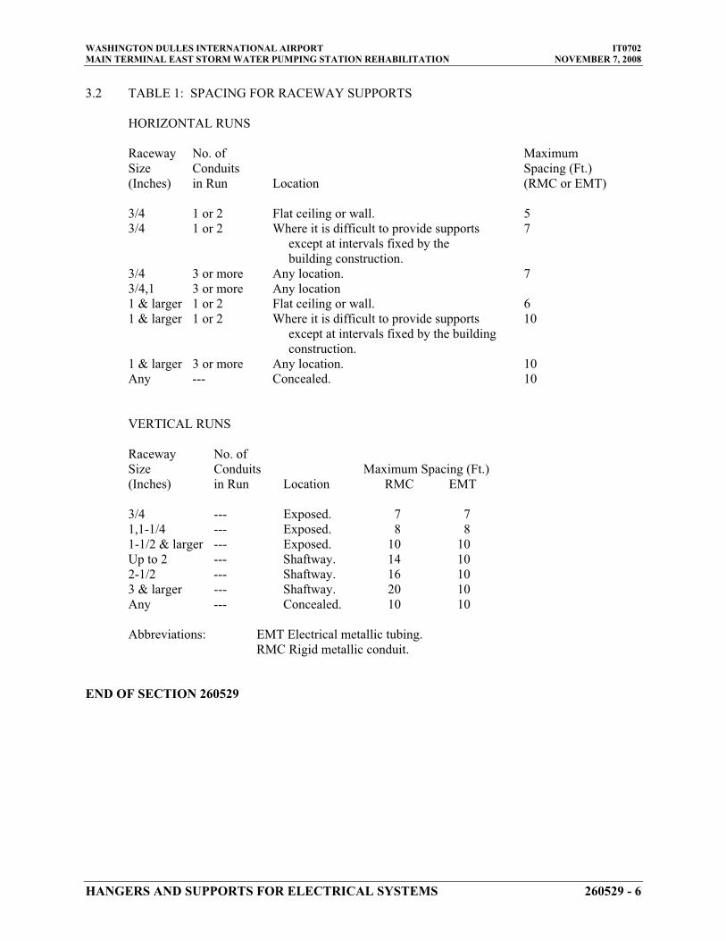
WASHINGTON DULLES INTERNATIONAL AIRPORT IT0702 MAIN TERMINAL EAST STORM WATER PUMPING STATION REHABILITATION NOVEMBER 7, 2008
3.2 TABLE 1: SPACING FOR RACEWAY SUPPORTS
HORIZONTAL RUNS
Raceway No. of Maximum Size Conduits Spacing (Ft.) (Inches) in Run Location (RMC or EMT)
3/4 1 or 2 Flat ceiling or wall. 53/4 1 or 2 Where it is difficult to provide supports 7
except at intervals fixed by the building construction.
3/4 3 or more Any location. 73/4,1 3 or more Any location 1 & larger 1 or 2 Flat ceiling or wall. 61 & larger 1 or 2 Where it is difficult to provide supports 10
except at intervals fixed by the building construction.
1 & larger 3 or more Any location. 10Any --- Concealed. 10
VERTICAL RUNS
Raceway No. of Size Conduits Maximum Spacing (Ft.) (Inches) in Run Location RMC EMT
3/4 --- Exposed. 7 7 1,1-1/4 --- Exposed. 8 8 1-1/2 & larger --- Exposed. 10 10 Up to 2 --- Shaftway. 14 10 2-1/2 --- Shaftway. 16 10 3 & larger --- Shaftway. 20 10 Any --- Concealed. 10 10
Abbreviations: EMT Electrical metallic tubing. RMC Rigid metallic conduit.
END OF SECTION 260529
HANGERS AND SUPPORTS FOR ELECTRICAL SYSTEMS 260529 - 6

WASHINGTON DULLES INTERNATIONAL AIRPORT IT0702 MAIN TERMINAL EAST STORM WATER PUMPING STATION REHABILITATION NOVEMBER 7, 2008
SECTION 260533 - RACEWAYS AND BOXES
PART 1 - GENERAL
1.1 RELATED DOCUMENTS
A. Drawings and general provisions of the Contract, including General and Supplementary Conditions and Division 01 Specification Sections, apply to this Section.
1.2 SUMMARY
A. This Section includes raceways, fittings, boxes, enclosures, and cabinets for electrical wiring.
B. Related Sections include the following:
1. Division 26 Section 260500, "Basic Electrical Materials and Methods" for supports, anchors, and identification products.
1.3 DEFINITIONS
A. EMT: Electrical metallic tubing conduit.
B. IMC: Intermediate metal conduit.
C. LFMC: Liquidtight flexible metal conduit.
D. RGS: Rigid galvanized steel conduit.
1.4 SUBMITTALS
A. Product Data: For surface raceways, wireways and fittings, hinged-cover enclosures, and cabinets.
B. Shop Drawings: Show fabrication and installation details of components for raceways, fittings, boxes, enclosures, and cabinets.
C. Shop Drawings: Signed and sealed by a qualified professional engineer.
1. Detail assemblies and indicate dimensions, weights, loads, required clearances, method of field assembly, components, and location and size of each field connection.
RACEWAYS AND BOXES 260533 - 1

WASHINGTON DULLES INTERNATIONAL AIRPORT IT0702 MAIN TERMINAL EAST STORM WATER PUMPING STATION REHABILITATION NOVEMBER 7, 2008
1.5 QUALITY ASSURANCE
A. Electrical Components, Devices, and Accessories: Listed and labeled as defined in NFPA 70, Article 100, by a testing agency acceptable to authorities having jurisdiction, and marked for intended use.
B. Comply with NFPA 70.
1.6 COORDINATION
A. Coordinate layout and installation of raceways, boxes, enclosures, and cabinets with other construction and assemblies.
PART 2 - PRODUCTS
2.1 MANUFACTURERS
A. In other Part 2 articles where subparagraph titles below introduce lists, the following requirements apply for product selection:
1. Available Manufacturers: Subject to compliance with requirements, manufacturers offering products that may be incorporated into the Work include, but are not limited to, the manufacturers specified.
2. Manufacturers: Subject to compliance with requirements, provide products by the manufacturers specified.
2.2 CONDUIT REQUIREMENTS
A. Interior Conduit:
1. Use EMT, ¾” minimum size, above ceilings. Do not use EMT where conduit will be exposed to physical damage.
2. Use RGS, ¾” minimum size, where conduit will be exposed to physical damage.
B. Exterior Conduit:
1. Use RGS, ¾” minimum size, in all exterior aboveground locations.
C. Underground Conduit:
1. Use rigid galvanized steel in locations required by drawings.
2.3 METAL CONDUIT
A. Rigid Steel Conduit shall be hot dip galvanized conforming to FS WWC 581, ANSI C80.1 and UL 6. Fittings shall be threaded type of galvanized malleable iron construc-tion.
RACEWAYS AND BOXES 260533 - 2

WASHINGTON DULLES INTERNATIONAL AIRPORT IT0702 MAIN TERMINAL EAST STORM WATER PUMPING STATION REHABILITATION NOVEMBER 7, 2008
1. Manufacturer: Allied Tube and Conduit, Grinnell Co., Triangle PWC Inc., Wheatland, or approved equal.
B. Electrical Metallic Tubing (EMT) shall conform to ANSI C80.3 with compression type fittings. Set-screw fittings shall not be used. Die-cast fittings shall not be used. Die-cast fittings are not allowed.
1. Manufacturer: Allied Tube and Conduit, Grinnell Co., Triangle PWC Inc., Wheatland, or approved equal.
2.4 LIQUIDTIGHT FLEXIBLE METAL CONDUIT
A. Liquid-tight Flexible Metal Conduit shall be constructed of single strip, flexible, continu-ous, interlocked and double-wrapped steel, galvanized inside and outside and coated with liquid-tight jacket of flexible polyvinyl chloride (PVC). Fittings shall be liquid-tight compression type. Provide conduit with a continuous copper-bonding conductor wound spirally between convolutions.
2.5 RACEWAY, FITTINGS, COUPLINGS, AND CONNECTORS
A. Use fittings listed and approved for specific conduit or raceway system used.
B. For threaded rigid steel conduit do not use threadless or compression type fittings.
C. Bushing and connectors shall be insulated type which maintain continuity of conduit grounding system. Insulating material shall be molded or locked into metallic body of the fitting. Bushing made entirely of nonmetallic material will not be allowed.
D. Set screw connectors and coupling bodies shall not be used.
E. Liquid-tight flexible metal conduit shall incorporate a threaded grounding cone, a steel, nylon or equal plastic compression ring and a gland for tightening. Fitting shall be steel, or malleable iron with insulated throat, with male thread and locknut or male bushing with or without "O" ring seal.
F. Expansion fittings shall be hot-dipped galvanized malleable iron with a packing ring to prevent entrance of water, a pressure ring, a grounding ring and a separate external cop-per bonding jumper.
G. Inferior material such as "pot metal" shall not be used for any type of fitting.
H. All locknuts shall be the bonding type with sharp edges for digging into the metal wall of an enclosure.
2.6 BOXES, ENCLOSURES, AND CABINETS
A. Manufacturers:
1. Cooper Crouse-Hinds; Div. of Cooper Industries, Inc.
RACEWAYS AND BOXES 260533 - 3

WASHINGTON DULLES INTERNATIONAL AIRPORT IT0702 MAIN TERMINAL EAST STORM WATER PUMPING STATION REHABILITATION NOVEMBER 7, 2008
2. Emerson/General Signal; Appleton Electric Company. 3. Erickson Electrical Equipment Co. 4. Hoffman. 5. Hubbell, Inc.; Killark Electric Manufacturing Co. 6. O-Z/Gedney; Unit of General Signal. 7. RACO; Division of Hubbell, Inc. 8. Robroy Industries, Inc.; Enclosure Division. 9. Scott Fetzer Co.; Adalet-PLM Division. 10. Spring City Electrical Manufacturing Co. 11. Thomas & Betts Corporation. 12. Walker Systems, Inc.; Wiremold Company (The). 13. Woodhead, Daniel Company; Woodhead Industries, Inc. Subsidiary.
B. Cast-Metal Outlet and Device Boxes: NEMA FB 1, Type FD, with gasketed cover.
C. Cast-Metal Pull and Junction Boxes: NEMA FB 1, with gasketed cover.
D. Hinged-Cover Enclosures: NEMA 250, Type 4, with continuous hinge cover and flush latch.
1. Metal Enclosures: Steel, finished inside and out with manufacturer's standard enamel.
E. Cabinets: NEMA 250, Type 4 galvanized steel box with removable interior panel and removable front, finished inside and out with manufacturer's standard enamel. Hinged door in front cover with flush latch and concealed hinge. Key latch to match panelboards. Include metal barriers to separate wiring of different systems and voltage and include accessory feet where required for freestanding equipment.
2.7 FACTORY FINISHES
F. Finish: For raceway, enclosure, or cabinet components, provide manufacturer's standard paint applied to factory-assembled surface raceways, enclosures, and cabinets before shipping.
PART 3 - EXECUTION
3.1 RACEWAY APPLICATION
A. Outdoors:
1. Exposed: Rigid steel or IMC. 2. Concealed: Rigid steel or IMC. 3. Underground Direct Buried: RGS. 4. Underground Concrete Encased: Schedule 40 PVC. 5. Connection to Equipment (Including transformers): LFMC. 6. Boxes and Enclosures: NEMA 250, Type 4. 7. Stub ups: Plastic Coated Rigid Steel conduit.
RACEWAYS AND BOXES 260533 - 4
WASHINGTON DULLES INTERNATIONAL AIRPORT IT0702 MAIN TERMINAL EAST STORM WATER PUMPING STATION REHABILITATION NOVEMBER 7, 2008
B. Minimum Raceway Size: 3/4-inch trade size.
C. Raceway Fittings: Compatible with raceways and suitable for use and location.
1. Intermediate Steel Conduit: Use threaded rigid steel conduit fittings. 2. PVC Externally Coated, Rigid Steel Conduits: Use only fittings approved for use
with that material. Patch all nicks and scrapes in PVC coating after installing conduits.
3.2 INSTALLATION
A. Complete raceway installation before starting conductor installation.
B. Support raceways as specified in Division 26 Section 260500, "Basic Electrical Materials and Methods."
C. Install temporary closures to prevent foreign matter from entering raceways.
D. Protect stub-ups from damage where conduits rise through concrete housekeeping slabs. Arrange so curved portions of bends are not visible above the finished slab.
E. Make bends and offsets so ID is not reduced. Keep legs of bends in the same plane and keep straight legs of offsets parallel, unless otherwise indicated.
F. Conceal conduit unless otherwise indicated.
G. Change from PVC conduit to plastic coated rigid steel conduit before rising above the concrete housekeeping pad.
H. Install exposed raceways parallel or at right angles to nearby surfaces or structural members and follow surface contours as much as possible.
1. Run parallel or banked raceways together on common supports. 2. Make parallel bends in parallel or banked runs. Use factory elbows only where
elbows can be installed parallel; otherwise, provide field bends for parallel raceways.
I. Join raceways with fittings designed and approved for that purpose and make joints tight.
1. Use insulating bushings to protect conductors.
J. Tighten set screws of threadless fittings with suitable tools.
K. Terminations:
1. Where raceways are terminated with locknuts and bushings, align raceways to enter squarely and install locknuts with dished part against box. Use two locknuts, one inside and one outside box.
2. Where raceways are terminated with threaded hubs, screw raceways or fittings tightly into hub so end bears against wire protection shoulder. Where chase
RACEWAYS AND BOXES 260533 - 5
WASHINGTON DULLES INTERNATIONAL AIRPORT IT0702 MAIN TERMINAL EAST STORM WATER PUMPING STATION REHABILITATION NOVEMBER 7, 2008
nipples are used, align raceways so coupling is square to box; tighten chase nipple so no threads are exposed.
L. Install pull wires in empty raceways. Use polypropylene or monofilament plastic line with not less than 200-lb tensile strength. Leave at least 12 inches of slack at each end of pull wire.
M. Stub-up Connections: Extend conduits through concrete housekeeping pads for connection to freestanding equipment. Install with an adjustable top or coupling threaded inside for plugs set flush with finished floor. Install screwdriver-operated, threaded plugs flush with floor for future equipment connections.
N. Flexible Connections: Use maximum of 72 inches of flexible conduit for connection to transformers. Install separate ground conductor across flexible connections.
O. Install hinged-cover enclosures and cabinets plumb. Support at each corner.
P. When threading metal conduit in field, threads shall be corrosion resistant.
3.3 PROTECTION
A. Provide final protection and maintain conditions that ensure coatings, finishes, and cabinets are without damage or deterioration at time of Substantial Completion.
1. Repair damage to galvanized finishes with zinc-rich paint recommended by manufacturer.
2. Repair damage to PVC or paint finishes with matching touchup coating recommended by manufacturer.
3.4 CLEANING
A. After completing installation of exposed, factory-finished raceways and boxes, inspect exposed finishes and repair damaged finishes.
END OF SECTION 260533
RACEWAYS AND BOXES 260533 - 6

WASHINGTON DULLES INTERNATIONAL AIRPORT IT0702 MAIN TERMINAL EAST STORM WATER PUMPING STATION REHABILITATION NOVEMBER 7, 2008
UNDERGROUND DUCTS AND RACEWAYS FOR ELECTRICAL SYSTEMS 260543 - 1
SECTION 260543 - UNDERGROUND DUCTS AND RACEWAYS FOR ELECTRICAL SYSTEMS
PART 1 - GENERAL
1.1 RELATED DOCUMENTS
A. Drawings and general provisions of the Contract, including General and Supplementary Conditions and Division 01 Specification Sections, apply to this Section.
1.2 SUMMARY
A. This Section includes the following:
1. Conduit, ducts, and duct accessories for direct-buried duct banks.
1.3 DEFINITION
A. RGS: Rigid galvanized steel conduit.
1.4 SUBMITTALS
A. Product Data: For the following:
1. Duct-bank materials, including separators and miscellaneous components. 2. Ducts and conduits and their accessories, including elbows, end bells, bends, fittings, and
solvent cement. 3. Warning tape.
B. Duct-Bank Coordination Drawings: Show duct profiles and coordination with other utilities and underground structures.
1. Include plans and sections, drawn to scale, and show bends and locations of expansion fittings.
2. Drawings shall be signed and sealed by a qualified professional engineer.
C. Qualification Data: For professional engineer and testing agency.
D. Source quality-control test reports.
E. Field quality-control test reports.
1.5 QUALITY ASSURANCE
A. Testing Agency Qualifications: Qualified according to ASTM E 329 for testing indicated.

WASHINGTON DULLES INTERNATIONAL AIRPORT IT0702 MAIN TERMINAL EAST STORM WATER PUMPING STATION REHABILITATION NOVEMBER 7, 2008
UNDERGROUND DUCTS AND RACEWAYS FOR ELECTRICAL SYSTEMS 260543 - 2
B. Comply with ANSI C2.
C. Comply with NFPA 70.
1.6 DELIVERY, STORAGE, AND HANDLING
A. Deliver ducts to Project site with ends capped.
1.7 PROJECT CONDITIONS
A. Interruption of Existing Electrical Service: Do not interrupt electrical service to facilities occupied by Owner or others unless permitted under the following conditions and then only after arranging to provide temporary electrical service according to requirements indicated:
1. Notify Authority no fewer than two days in advance of proposed interruption of electrical service.
2. Do not proceed with interruption of electrical service without Authority’s written permission.
1.8 COORDINATION
A. Coordinate layout and installation of ducts, manholes, handholes, and boxes with final arrangement of other utilities, site grading, and surface features as determined in the field.
B. Coordinate elevations of ducts and duct-bank entrances into manholes, handholes, and boxes with final locations and profiles of ducts and duct banks as determined by coordination with other utilities, underground obstructions, and surface features. Revise locations and elevations from those indicated as required to suit field conditions and to ensure that duct runs drain to manholes and handholes, and as approved by Architect.
1.9 EXTRA MATERIALS
A. Furnish extra materials described below that match products installed and that are packaged with protective covering for storage and identified with labels describing contents.
PART 2 - PRODUCTS
2.1 CONDUIT
A. Rigid Steel Conduit: Galvanized. Comply with ANSI C80.1.

WASHINGTON DULLES INTERNATIONAL AIRPORT IT0702 MAIN TERMINAL EAST STORM WATER PUMPING STATION REHABILITATION NOVEMBER 7, 2008
UNDERGROUND DUCTS AND RACEWAYS FOR ELECTRICAL SYSTEMS 260543 - 3
PART 3 - EXECUTION
3.1 UNDERGROUND DUCT APPLICATION
A. Ducts for Electrical Feeders 600 V and Less: RGS, in direct-buried duct bank, unless otherwise indicated.
B. Ducts for Electrical Branch Circuits: RGS, in direct-buried duct bank, unless otherwise indicated.
C. Underground Ducts for Telephone, Communications, or Data Circuits: RGS, in direct-buried duct bank, unless otherwise indicated.
3.2 EARTHWORK
A. Excavation and Backfill: Comply with Division 31 Section "Earth Moving," but do not use heavy-duty, hydraulic-operated, compaction equipment.
B. Restore surface features at areas disturbed by excavation and reestablish original grades, unless otherwise indicated. Replace removed sod immediately after backfilling is completed.
C. Restore areas disturbed by trenching, storing of dirt, cable laying, and other work. Restore vegetation and include necessary topsoiling, fertilizing, liming, seeding, sodding, sprigging, and mulching. Comply with Division 32 Section "Turf and Grasses."
3.3 DUCT INSTALLATION
A. Slope: Pitch ducts a minimum slope of 1:300 down toward manholes and handholes and away from buildings and equipment. Slope ducts from a high point in runs between two manholes to drain in both directions.
B. Curves and Bends: Use 5-degree angle couplings for small changes in direction. Use manufactured long sweep bends with a minimum radius of [48 inches (1220 mm)], both horizontally and vertically, at other locations, unless otherwise indicated.
C. Joints: Use solvent-cemented joints in ducts and fittings and make watertight according to manufacturer's written instructions. Stagger couplings so those of adjacent ducts do not lie in same plane.
D. Duct Entrances to Concrete Vaults: Use end bells, spaced approximately 10 inches (250 mm)o.c. for 5-inch (125-mm) ducts, and vary proportionately for other duct sizes.
1. Begin change from regular spacing to end-bell spacing 10 feet (3 m) from the end bell without reducing duct line slope and without forming a trap in the line.
2. Direct-Buried Duct Banks: Install an expansion and deflection fitting in each conduit in the area of disturbed earth adjacent to manhole or handhole.
3. Grout end bells into structure walls from both sides to provide watertight entrances.

WASHINGTON DULLES INTERNATIONAL AIRPORT IT0702 MAIN TERMINAL EAST STORM WATER PUMPING STATION REHABILITATION NOVEMBER 7, 2008
UNDERGROUND DUCTS AND RACEWAYS FOR ELECTRICAL SYSTEMS 260543 - 4
E. Sealing: Provide temporary closure at terminations of ducts that have cables pulled. Seal spare ducts at terminations. Use sealing compound and plugs to withstand at least 15-psig (1.03-MPa) hydrostatic pressure.
F. Pulling Cord: Install 100-lbf- (445-N-) test nylon cord in ducts, including spares.
G. Direct-Buried Duct Banks:
1. Support ducts on duct separators coordinated with duct size, duct spacing, and outdoor temperature.
2. Space separators close enough to prevent sagging and deforming of ducts, with not less than 4 spacers per 20 feet (6 m) of duct. Secure separators to earth and to ducts to prevent displacement during backfill and yet permit linear duct movement due to expansion and contraction as temperature changes. Stagger spacers approximately 6inches (150 mm) between tiers.
3. Excavate trench bottom to provide firm and uniform support for duct bank. Prepare trench bottoms as specified in Division 31 Section "Earth Moving" for pipes less than 6inches (150 mm) in nominal diameter.
4. Install backfill as specified in Division 31 Section "Earth Moving." 5. After installing first tier of ducts, backfill and compact. Start at tie-in point and work
toward end of duct run, leaving ducts at end of run free to move with expansion and contraction as temperature changes during this process. Repeat procedure after placing each tier. After placing last tier, hand-place backfill to 4 inches (100 mm) over ducts and hand tamp. Firmly tamp backfill around ducts to provide maximum supporting strength. Use hand tamper only. After placing controlled backfill over final tier, make final duct connections at end of run and complete backfilling with normal compaction as specified in Division 31 Section "Earth Moving."
6. Install ducts with a minimum of 3 inches (75 mm) between ducts for like services and 6inches (150 mm) between power and signal ducts.
7. Depth: Install top of duct bank at least 36 inches (900 mm) below finished grade, unless otherwise indicated.
8. Set elevation of bottom of duct bank below the frost line. 9. Install manufactured duct elbows for stub-ups at poles and equipment and at building
entrances through the floor, unless otherwise indicated. Encase elbows for stub-up ducts throughout the length of the elbow.
10. Install manufactured rigid steel conduit elbows for stub-ups at poles and equipment and at building entrances through the floor.
a. Couple steel conduits to ducts with adapters designed for this purpose, and encase coupling with 3 inches (75 mm) of concrete.
b. For equipment mounted on outdoor concrete bases, extend steel conduit horizontally a minimum of 60 inches (1500 mm) from edge of equipment pad or foundation. Install insulated grounding bushings on terminations at equipment.
3.4 GROUNDING
A. Ground underground ducts and utility structures according to Division 26 Section "Grounding and Bonding for Electrical Systems."

WASHINGTON DULLES INTERNATIONAL AIRPORT IT0702 MAIN TERMINAL EAST STORM WATER PUMPING STATION REHABILITATION NOVEMBER 7, 2008
UNDERGROUND DUCTS AND RACEWAYS FOR ELECTRICAL SYSTEMS 260543 - 5
3.5 FIELD QUALITY CONTROL
A. Perform the following tests and inspections and prepare test reports:
1. Demonstrate capability and compliance with requirements on completion of installation of underground ducts and utility structures.
2. Pull aluminum or wood test mandrel through duct to prove joint integrity and test for out-of-round duct. Provide mandrel equal to 80 percent fill of duct. If obstructions are indicated, remove obstructions and retest.
3. Test vault grounding to ensure electrical continuity of grounding and bonding connections. Measure and report ground resistance as specified in Division 26 Section "Grounding and Bonding for Electrical Systems."
B. Correct deficiencies and retest as specified above to demonstrate compliance.
3.6 CLEANING
A. Pull leather-washer-type duct cleaner, with graduated washer sizes, through full length of ducts. Follow with rubber duct swab for final cleaning and to assist in spreading lubricant throughout ducts.
B. Clean internal surfaces of manholes, including sump. Remove foreign material.
END OF SECTION 260543

WASHINGTON DULLES INTERNATIONAL AIRPORT IT0702 MAIN TERMINAL EAST STORM WATER PUMPING STATION REHABILITATION NOVEMBER 7, 2008
UNDERGROUND DUCTS AND RACEWAYS FOR ELECTRICAL SYSTEMS 260543 - 6
THIS PAGE INTENTIONALLY LEFT BLANK

WASHINGTON DULLES INTERNATIONAL AIRPORT IT0702 MAIN TERMINAL EAST STORM WATER PUMPING STATION REHABILITATION NOVEMBER 7, 2008
SECTION 260553 - IDENTIFICATION FOR ELECTRICAL SYSTEMS
PART 1 - GENERAL
1.1 RELATED DOCUMENTS
A. Drawings and general provisions of Contract, including General and Supplementary Conditions and Division 01 Specification Sections, apply to this Section.
1.2 SUMMARY
A. This Section specifies electrical identification materials and includes requirements for electrical identification including but not limited to the following:
1. Identification labeling for raceways, cables, and conductors. 2. Operational instruction signs. 3. Warning and caution signs. 4. Equipment labels and signs.
B. Refer to other Division 26 sections for additional specific electrical identification associ-ated with specific items.
1.3 SUBMITTALS
A. Product Data for each type of product specified.
B. Schedule of all tags, markers, nameplates, signs, etc.
1.4 QUALITY ASSURANCE
A. Electrical Component Standard: Components and installation shall comply with NFPA 70 "National Electrical Code."
B. Comply with manufacturers’ instructions.
PART 2 - PRODUCTS
2.1 MANUFACTURERS
A. Manufacturers: Subject to compliance with requirements, provide products by the follow-ing:
1. American Engraving Co. 2. Seton Name Plate Co. 3. Standard Signs, Inc. 4. W.H.Brady, Co.
5. Almetek Industries 6. Tech Products, Inc.
IDENTIFICATION FOR ELECTRICAL SYSTEMS 260553 - 1

WASHINGTON DULLES INTERNATIONAL AIRPORT IT0702 MAIN TERMINAL EAST STORM WATER PUMPING STATION REHABILITATION NOVEMBER 7, 2008
7. William Frick & Company8. Thomas & Betts
2.2 ELECTRICAL IDENTIFICATION PRODUCTS
A. Engraved, Plastic Laminated Labels, Signs, and Instruction Plates: Engraving stock me-lamine plastic laminate, 1/16-inch minimum thick for signs up to 20 square inches, or 8 inches in length; 1/8-inch thick for larger sizes. Drill holes for mechanical fasteners when mounted indoors.
B. Baked Enamel Warning and Caution Signs for Interior Use: Preprinted aluminum signs, punched for fasteners, with colors, legend, and size appropriate to the location.
C. Exterior Metal Backed Butyrate Warning and Caution Signs: Weather resistant, nonfad-ing, preprinted cellulose acetate butyrate signs with 20-gage galvanized steel backing, with colors, legend, and size appropriate to the location. Provide 1/4-inch grommets in corners for mounting.
D. Fasteners for Plastic Laminated and Metal Signs: Self tapping stainless steel screws or number 10/32 stainless steel machine screws with nuts and flat and lock washers.
E. Cable Ties: Fungus inert, self extinguishing, one piece, self locking nylon cable ties, 0.18-inch minimum width, 50-lb minimum tensile strength, and suitable for a temperature range from minus 50 deg F to 350 deg F.
F. Cable Markers: Provide "E-Z Tag" as manufactured by Almetek Industries Inc., or “Everlast” tags as manufactured by Tech Products Inc. Tags shall consist of 1.0 inch high numerals or letters placed in a tag holder. Tags and holder shall be manufactured from U.V. stabilized non-conductive, non-corrosive polyethylene or equal. Tag holder shall be black and numerals and letters shall be black on yellow background. Numerals and letters shall be oriented either horizontally or vertically depending on orientation of cable. For systems over 600 volts AC, use white lettering on blue background. For sys-tems 480 volts AC and less use black lettering on yellow background.
G. Pressure Sensitive Markers for Outdoor Equipment: Provide markers as manufactured by Almetek Industries or William Frick & Company or equal. Provide minimum 1.0 inch high numerals or letters. On medium voltage equipment provide markers that are black on reflective yellow background. On low voltage equipment provide markers which are black on reflective silver background. Markers shall be resistant to U.V. light.
PART 3 - EXECUTION
3.1 INSTALLATION
A. Lettering and Graphics: Coordinate names, abbreviations, colors, and other designations with corresponding designations specified or indicated. Install numbers, lettering, and colors as approved in submittals and as required by code.
IDENTIFICATION FOR ELECTRICAL SYSTEMS 260553 - 2

WASHINGTON DULLES INTERNATIONAL AIRPORT IT0702 MAIN TERMINAL EAST STORM WATER PUMPING STATION REHABILITATION NOVEMBER 7, 2008
B. Install identification products in accordance with manufacturer's written instructions and requirements of NEC.
C. Sequence of Work: Where identification is to be applied to surfaces that require finish, install identification after completion of finish work.
D. Medium Voltage Cable Identification: In manholes indicate voltage, feeder number and phase letter on each cable. Inside equipment indicate phase letter on each cable. Install markers on cables after arc proofing is applied. Attach with cable ties.
E. Low Voltage Conductor Color Coding: Provide color coding for as follows:
208/120 Volts Phase 480/277 Volts
Black A YellowRed B BrownBlue C OrangeWhite Neutral Gray Green Ground Green
F. Use low voltage conductors with color factory-applied the entire length of the conductors except as follows:
1. The following color coding methods may be used in lieu of factory color coded wire for sizes No. 4 AWG and Larger.
a. Apply colored, pressure-sensitive plastic tape in half lapped turns for a distance of 6 inches from terminal points and in boxes where splices or taps are made. Apply the last two laps of tape with no tension to prevent possible unwinding.
G. Provide warning, caution, and instruction signs as follows:
1. Install warning, caution, or instruction signs where required by NEC, where indi-cated, or where required for safe operation and maintenance of electrical systems. Install engraved plastic laminated instruction signs where instructions or explana-tions are needed for system or equipment operation. Install butyrate signs with metal backing for outdoor items. Attach signs to outdoor equipment using two part epoxy cement.
2. Emergency Operating Signs: Where required provide engraved laminate signs with white legend on red background with minimum 3/8-inch high lettering for emergency instructions.
H. Provide equipment/system, circuit/device identification as follows:
1. Provide engraved plastic laminate identification markers on electrical equipment. For 240V systems and below provide white lettering on black background. For 480/277V systems, use black lettering on yellow background. Text shall match
IDENTIFICATION FOR ELECTRICAL SYSTEMS 260553 - 3

WASHINGTON DULLES INTERNATIONAL AIRPORT IT0702 MAIN TERMINAL EAST STORM WATER PUMPING STATION REHABILITATION NOVEMBER 7, 2008
terminology and numbering of the Contract Documents and shop drawings. Ap-ply markers on all of the following:
a. Panelboards, electrical cabinets, and enclosures. b. Electrical switchgear and switchboards. c. Electrical substations. d. Power transfer equipment. e. Contactors. f. Transformers. g Disconnect switches. h Control equipment. i. Circuit breakers
I. Circuit Schedules: For panelboards provide typed circuit schedules with identification of items controlled by each breaker.
J. Install labels, tags and markers at locations for best convenience of viewing without inter-ference with operation and maintenance of equipment.
K. Pad Mounted Equipment: Place 1.0 inch high, black on reflective yellow marker indicat-ing voltage and circuit number in upper left corner of exterior of door securing feeder compartment. Where two feeders enter a compartment place marker on exterior of door along top edge opposite respective feeder.
L. Pad Mounted Transformers: Using 3.0 inch high, black on reflective yellow pressure sen-sitive markers, identify transformer size (i.e., 45KVA). Centrally locate marker on exte-rior of high voltage compartment door. Identify feeders per paragraph "K" and "D" above.
M. Raceway: Identify with pressure sensitive markers purpose of circuit ( i.e., lighting, pow-er, alarm, signal, PA., etc.). Place marker on junction boxes and along raceway on 150 foot centers. Markers shall be black on white background.
N. Pad Mounted Switches: Identify switch operating handles sequentially beginning with number 1. Use markers 1.0 inch high, pressure sensitive, black on reflective yellow back-ground. Place marker adjacent to operating handle on exterior of enclosure.
END OF SECTION 260553
IDENTIFICATION FOR ELECTRICAL SYSTEMS 260553 - 4
WASHINGTON DULLES INTERNATIONAL AIRPORT IT0702 MAIN TERMINAL EAST STORM WATER PUMPING STATION REHABILITATION NOVEMBER 7, 2008
SECTION 262200 - LOW-VOLTAGE TRANSFORMERS
PART 1 - GENERAL
1.1 RELATED DOCUMENTS
A. Drawings and general provisions of the Contract, including General and Supplementary Conditions and Division 01 Specification Sections, apply to this Section.
1.2 SUMMARY
A. This Section includes the following types of dry-type transformers rated 600 V and less, with capacities up to 1000 kVA:
1. Distribution transformers.
1.3 SUBMITTALS
A. Product Data: Include rated nameplate data, capacities, weights, dimensions, minimum clearances, installed devices and features, and performance for each type and size of transformer indicated.
B. Shop Drawings: Detail equipment assemblies and indicate dimensions, weights, loads, required clearances, method of field assembly, components, and location and size of each field connection.
1. Wiring Diagrams: Power, signal, and control wiring.
C. Qualification Data: For testing agency.
D. Source quality-control test reports.
E. Field quality-control test reports.
F. Operation and Maintenance Data: For transformers to include in emergency, operation, and maintenance manuals.
1.4 QUALITY ASSURANCE
A. Testing Agency Qualifications: An independent agency, with the experience and capability to conduct the testing indicated, that is a member company of the InterNational Electrical Testing Association or is a nationally recognized testing laboratory (NRTL) as defined by OSHA in 29 CFR 1910.7, and that is acceptable to authorities having jurisdiction.
LOW-VOLTAGE TRANSFORMERS 262200 - 1

WASHINGTON DULLES INTERNATIONAL AIRPORT IT0702 MAIN TERMINAL EAST STORM WATER PUMPING STATION REHABILITATION NOVEMBER 7, 2008
1. Testing Agency's Field Supervisor: Person currently certified by the InterNational Electrical Testing Association or the National Institute for Certification in Engineering Technologies to supervise on-site testing specified in Part 3.
B. Testing Agency Qualifications: An independent agency, with the experience and capability to conduct the testing indicated, that is a nationally recognized testing laboratory (NRTL) as defined by OSHA in 29 CFR 1910.7.
C. Source Limitations: Obtain each transformer type through one source from a single manufacturer.
D. Electrical Components, Devices, and Accessories: Listed and labeled as defined in NFPA 70, Article 100, by a testing agency acceptable to authorities having jurisdiction, and marked for intended use.
E. Comply with IEEE C57.12.91, "Test Code for Dry-Type Distribution and Power Transformers."
1.5 DELIVERY, STORAGE, AND HANDLING
A. Temporary Heating: Apply temporary heat according to manufacturer's written instructions within the enclosure of each ventilated-type unit, throughout periods during which equipment is not energized and when transformer is not in a space that is continuously under normal control of temperature and humidity.
1.6 COORDINATION
A. Coordinate size and location of concrete bases with actual transformer provided. Cast anchor-bolt inserts into bases. Concrete, reinforcement, and formwork requirements are specified in Division 03.
B. Coordinate installation of wall-mounting and structure-hanging supports with actual transformer provided.
PART 2 - PRODUCTS
2.1 MANUFACTURERS
A. Available Manufacturers: Subject to compliance with requirements, manufacturers offering products that may be incorporated into the Work include, but are not limited to, the following:
1. ACME Electric Corporation; Power Distribution Products Division. 2. Challenger Electrical Equipment Corp.; a division of Eaton Corp. 3. Controlled Power Company. 4. Eaton Electrical Inc.; Cutler-Hammer Products. 5. Federal Pacific Transformer Company; Division of Electro-Mechanical Corp. 6. General Electric Company. 7. Hammond Co.; Matra Electric, Inc. 8. Magnetek Power Electronics Group.
LOW-VOLTAGE TRANSFORMERS 262200 - 2

WASHINGTON DULLES INTERNATIONAL AIRPORT IT0702 MAIN TERMINAL EAST STORM WATER PUMPING STATION REHABILITATION NOVEMBER 7, 2008
9. Micron Industries Corp. 10. Myers Power Products, Inc. 11. Siemens Energy & Automation, Inc. 12. Sola/Hevi-Duty.13. Square D; Schneider Electric.
2.2 GENERAL TRANSFORMER REQUIREMENTS
A. Description: Factory-assembled and -tested, air-cooled units for 60-Hz service.
B. Cores: Grain-oriented, non-aging silicon steel.
C. Coils: Continuous windings without splices except for taps.
1. Internal Coil Connections: Brazed or pressure type. 2. Coil Material: Copper.
2.3 DISTRIBUTION TRANSFORMERS
A. Comply with NEMA ST 20, and list and label as complying with UL 1561.
B. Cores: One leg per phase.
C. Enclosure: Ventilated NEMA 250, Type 2.
1. Core and coil shall be encapsulated within resin compound, sealing out moisture and air.
D. Enclosure: Ventilated, NEMA 250, Type 3R.
1. Core and coil shall be encapsulated within resin compound, sealing out moisture and air.
E. Transformer Enclosure Finish: Comply with NEMA 250.
1. Finish Color: Gray.
F. Taps for Transformers Smaller Than 3 kVA: None.
G. Taps for Transformers 7.5 to 24 kVA: One 5 percent tap above and one 5 percent tap below normal full capacity.
H. Taps for Transformers 25 kVA and Larger: Two 2.5 percent taps above and four 2.5 percent taps below normal full capacity.
I. Insulation Class: 220 deg C, UL-component-recognized insulation system with a maximum of 115 deg C rise above 40 deg C ambient temperature.
J. Energy Efficiency for Transformers Rated 15 kVA and Larger:
1. Complying with NEMA TP 1, Class 1 efficiency levels. 2. Tested according to NEMA TP 2.
LOW-VOLTAGE TRANSFORMERS 262200 - 3
WASHINGTON DULLES INTERNATIONAL AIRPORT IT0702 MAIN TERMINAL EAST STORM WATER PUMPING STATION REHABILITATION NOVEMBER 7, 2008
K. K-Factor Rating: Transformers indicated to be K-factor rated shall comply with UL 1561 requirements for nonsinusoidal load current-handling capability to the degree defined by designated K-factor.
1. Unit shall not overheat when carrying full-load current with harmonic distortion corresponding to designated K-factor.
2. Indicate value of K-factor on transformer nameplate.
L. Electrostatic Shielding: Each winding shall have an independent, single, full-width copper electrostatic shield arranged to minimize interwinding capacitance.
1. Arrange coil leads and terminal strips to minimize capacitive coupling between input and output terminals.
2. Include special terminal for grounding the shield. 3. Shield Effectiveness:
a. Capacitance between Primary and Secondary Windings: Not to exceed 33 picofarads over a frequency range of 20 Hz to 1 MHz.
b. Common-Mode Noise Attenuation: Minimum of minus 120 dBA at 0.5 to 1.5 kHz; minimum of minus 65 dBA at 1.5 to 100 kHz.
c. Normal-Mode Noise Attenuation: Minimum of minus 52 dBA at 1.5 to 10 kHz.
M. Wall Brackets: Manufacturer's standard brackets.
N. Fungus Proofing: Permanent fungicidal treatment for coil and core.
O. Low-Sound-Level Requirements: Minimum of 3 dBA less than NEMA ST 20 standard sound levels when factory tested according to IEEE C57.12.91.
2.4 IDENTIFICATION DEVICES
A. Nameplates: Engraved, laminated-plastic or metal nameplate for each distribution transformer, mounted with corrosion-resistant screws. Nameplates and label products are specified in Division 26 Section "Identification for Electrical Systems."
2.5 SOURCE QUALITY CONTROL
A. Test and inspect transformers according to IEEE C57.12.91.
B. Factory Sound-Level Tests: Conduct sound-level tests on equipment for this Project.
PART 3 - EXECUTION
3.1 EXAMINATION
A. Examine conditions for compliance with enclosure- and ambient-temperature requirements for each transformer.
LOW-VOLTAGE TRANSFORMERS 262200 - 4

WASHINGTON DULLES INTERNATIONAL AIRPORT IT0702 MAIN TERMINAL EAST STORM WATER PUMPING STATION REHABILITATION NOVEMBER 7, 2008
B. Verify that field measurements are as needed to maintain working clearances required by NFPA 70 and manufacturer's written instructions.
C. Examine walls, floors, roofs, and concrete bases for suitable mounting conditions where transformers will be installed.
D. Verify that ground connections are in place and requirements in Division 26 Section "Grounding and Bonding for Electrical Systems" have been met. Maximum ground resistance shall be 5 ohms at location of transformer.
E. Proceed with installation only after unsatisfactory conditions have been corrected.
3.2 INSTALLATION
A. Install wall-mounting transformers level and plumb with wall brackets fabricated by transformer manufacturer.
3.3 CONNECTIONS
A. Ground equipment according to Division 26 Section "Grounding and Bonding for Electrical Systems."
B. Connect wiring according to Division 26 Section "Low-Voltage Electrical Power Conductors and Cables."
3.4 FIELD QUALITY CONTROL
A. Testing Agency: Engage a qualified testing agency to perform tests and inspections and prepare test reports.
B. Manufacturer's Field Service: Engage a factory-authorized service representative to inspect, test, and adjust components, assemblies, and equipment installations, including connections. Report results in writing.
C. Perform tests and inspections and prepare test reports.
1. Manufacturer's Field Service: Engage a factory-authorized service representative to inspect components, assemblies, and equipment installations, including connections, and to assist in testing.
D. Tests and Inspections:
1. Perform each visual and mechanical inspection and electrical test stated in NETA Acceptance Testing Specification. Certify compliance with test parameters.
E. Remove and replace units that do not pass tests or inspections and retest as specified above.
F. Infrared Scanning: Two months after Substantial Completion, perform an infrared scan of transformer connections.
LOW-VOLTAGE TRANSFORMERS 262200 - 5

WASHINGTON DULLES INTERNATIONAL AIRPORT IT0702 MAIN TERMINAL EAST STORM WATER PUMPING STATION REHABILITATION NOVEMBER 7, 2008
1. Use an infrared-scanning device designed to measure temperature or detect significant deviations from normal values. Provide documentation of device calibration.
2. Perform 2 follow-up infrared scans of transformers, one at 4 months and the other at 11 months after Substantial Completion.
3. Prepare a certified report identifying transformer checked and describing results of scanning. Include notation of deficiencies detected, remedial action taken, and scanning observations after remedial action.
G. Test Labeling: On completion of satisfactory testing of each unit, attach a dated and signed "Satisfactory Test" label to tested component.
3.5 ADJUSTING
A. Record transformer secondary voltage at each unit for at least 48 hours of typical occupancy period. Adjust transformer taps to provide optimum voltage conditions at secondary terminals. Optimum is defined as not exceeding nameplate voltage plus 10 percent and not being lower than nameplate voltage minus 3 percent at maximum load conditions. Submit recording and tap settings as test results.
B. Output Settings Report: Prepare a written report recording output voltages and tap settings.
3.6 CLEANING
A. Vacuum dirt and debris; do not use compressed air to assist in cleaning.
END OF SECTION 262200
LOW-VOLTAGE TRANSFORMERS 262200 - 6
WASHINGTON DULLES INTERNATIONAL AIRPORT IT0702 MAIN TERMINAL EAST STORM WATER PUMPING STATION REHABILITATION NOVEMBER 7, 2008
SECTION 262416 - PANELBOARDS
PART 1 - GENERAL
1.1 RELATED DOCUMENTS
A. Drawings and general provisions of the Contract, including General and Supplementary Conditions and Division 01 Specification Sections, apply to this Section.
1.2 SUMMARY
A. Section Includes:
1. Distribution panelboards. 2. Lighting and appliance branch-circuit panelboards.
1.3 DEFINITIONS
A. SVR: Suppressed voltage rating.
B. TVSS: Transient voltage surge suppressor.
1.4 SUBMITTALS
A. Product Data: For each type of panelboard, switching and overcurrent protective device, transient voltage suppression device, accessory, and component indicated. Include dimensions and manufacturers' technical data on features, performance, electrical characteristics, ratings, and finishes.
B. Shop Drawings: For each panelboard and related equipment.
1. Include dimensioned plans, elevations, sections, and details. Show tabulations of installed devices, equipment features, and ratings.
2. Detail enclosure types and details for types other than NEMA 250, Type 1. 3. Detail bus configuration, current, and voltage ratings. 4. Short-circuit current rating of panelboards and overcurrent protective devices. 5. Include evidence of NRTL listing for series rating of installed devices. 6. Detail features, characteristics, ratings, and factory settings of individual overcurrent
protective devices and auxiliary components. 7. Include wiring diagrams for power, signal, and control wiring. 8. Include time-current coordination curves for each type and rating of overcurrent
protective device included in panelboards. Submit on translucent log-log graft paper; include selectable ranges for each type of overcurrent protective device.
C. Qualification Data: For qualified testing agency.
PANELBOARDS 262416 - 1

WASHINGTON DULLES INTERNATIONAL AIRPORT IT0702 MAIN TERMINAL EAST STORM WATER PUMPING STATION REHABILITATION NOVEMBER 7, 2008
D. Field Quality-Control Reports:
1. Test procedures used. 2. Test results that comply with requirements. 3. Results of failed tests and corrective action taken to achieve test results that comply with
requirements.
E. Panelboard Schedules: For installation in panelboards.
F. Operation and Maintenance Data: For panelboards and components to include in emergency, operation, and maintenance manuals. In addition to items specified in Division 01 Section "Operation and Maintenance Data," include the following:
1. Manufacturer's written instructions for testing and adjusting overcurrent protective devices.
2. Time-current curves, including selectable ranges for each type of overcurrent protective device that allows adjustments.
1.5 QUALITY ASSURANCE
A. Testing Agency Qualifications: Member company of NETA or an NRTL.
1. Testing Agency's Field Supervisor: Currently certified by NETA to supervise on-site testing.
B. Source Limitations: Obtain panelboards, overcurrent protective devices, components, and accessories from single source from single manufacturer.
C. Product Selection for Restricted Space: Drawings indicate maximum dimensions for panelboards including clearances between panelboards and adjacent surfaces and other items. Comply with indicated maximum dimensions.
D. Electrical Components, Devices, and Accessories: Listed and labeled as defined in NFPA 70, by a qualified testing agency, and marked for intended location and application.
E. Comply with NEMA PB 1.
F. Comply with NFPA 70.
1.6 DELIVERY, STORAGE, AND HANDLING
A. Remove loose packing and flammable materials from inside panelboards; install temporary electric heating (250 W per panelboard) to prevent condensation.
B. Handle and prepare panelboards for installation according to NEMA PB 1.
1.7 PROJECT CONDITIONS
A. Environmental Limitations:
PANELBOARDS 262416 - 2

WASHINGTON DULLES INTERNATIONAL AIRPORT IT0702 MAIN TERMINAL EAST STORM WATER PUMPING STATION REHABILITATION NOVEMBER 7, 2008
1. Do not deliver or install panelboards until spaces are enclosed and weathertight, wet work in spaces is complete and dry, work above panelboards is complete, and temporary HVAC system is operating and maintaining ambient temperature and humidity conditions at occupancy levels during the remainder of the construction period.
2. Rate equipment for continuous operation under the following conditions unless otherwise indicated:
a. Ambient Temperature: Not exceeding minus 22 deg F to plus 104 deg F.b. Altitude: Not exceeding 6600 feet (2000 m).
B. Service Conditions: NEMA PB 1, usual service conditions, as follows:
1. Ambient temperatures within limits specified. 2. Altitude not exceeding 6600 feet (2000 m).
C. Interruption of Existing Electric Service: Do not interrupt electric service to facilities occupied by Owner or others unless permitted under the following conditions and then only after arranging to provide temporary electric service according to requirements indicated:
1. Notify MWAA no fewer than two days in advance of proposed interruption of electric service.
2. Do not proceed with interruption of electric service without MWAA written permission. 3. Comply with NFPA 70E.
1.8 COORDINATION
A. Coordinate layout and installation of panelboards and components with other construction that penetrates walls or is supported by them, including electrical and other types of equipment, raceways, piping, encumbrances to workspace clearance requirements, and adjacent surfaces. Maintain required workspace clearances and required clearances for equipment access doors and panels.
B. Coordinate sizes and locations of concrete bases with actual equipment provided. Cast anchor-bolt inserts into bases. Concrete, reinforcement, and formwork requirements are specified in Division 03.
1.9 WARRANTY
A. Special Warranty: Manufacturer's standard form in which manufacturer agrees to repair or replace transient voltage suppression devices that fail in materials or workmanship within specified warranty period.
1. Warranty Period: Five years from date of Substantial Completion.
1.10 EXTRA MATERIALS
A. Furnish extra materials that match products installed and that are packaged with protective covering for storage and identified with labels describing contents.
PANELBOARDS 262416 - 3

WASHINGTON DULLES INTERNATIONAL AIRPORT IT0702 MAIN TERMINAL EAST STORM WATER PUMPING STATION REHABILITATION NOVEMBER 7, 2008
1. Keys: Two spares for each type of panelboard cabinet lock. 2. Circuit Breakers Including GFCI and Ground Fault Equipment Protection (GFEP) Types:
Two spares for each panelboard. 3. Fuses for Fused Switches: Equal to 10 percent of quantity installed for each size and
type, but no fewer than three of each size and type. 4. Fuses for Fused Power-Circuit Devices: Equal to 10 percent of quantity installed for
each size and type, but no fewer than three of each size and type.
PART 2 - PRODUCTS
2.1 GENERAL REQUIREMENTS FOR PANELBOARDS
A. Enclosures: Surface-mounted cabinets.
1. Rated for environmental conditions at installed location.
a. Indoor Dry and Clean Locations: NEMA 250, Type 1 b. Outdoor Locations: NEMA 250, Type 3R. c. Other Wet or Damp Indoor Locations: NEMA 250, Type 4.
2. Front: Secured to box with concealed trim clamps. For surface-mounted fronts, match box dimensions; for flush-mounted fronts, overlap box.
3. Hinged Front Cover: Entire front trim hinged to box and with standard door within hinged trim cover.
4. Skirt for Surface-Mounted Panelboards: Same gage and finish as panelboard front with flanges for attachment to panelboard, wall, and ceiling or floor.
5. Gutter Extension and Barrier: Same gage and finish as panelboard enclosure; integral with enclosure body. Arrange to isolate individual panel sections.
6. Finishes:
a. Panels and Trim: Galvanized steel, factory finished immediately after cleaning and pretreating with manufacturer's standard two-coat, baked-on finish consisting of prime coat and thermosetting topcoat.
b. Back Boxes: Galvanized steel. c. Fungus Proofing: Permanent fungicidal treatment for overcurrent protective
devices and other components.
7. Directory Card: Inside panelboard door, mounted in transparent card holder.
B. Incoming Mains Location: Top and bottom.
C. Phase, Neutral, and Ground Buses:
1. Material: Hard-drawn copper, 98 percent conductivity. 2. Equipment Ground Bus: Adequate for feeder and branch-circuit equipment grounding
conductors; bonded to box. 3. Isolated Ground Bus: Adequate for branch-circuit isolated ground conductors; insulated
from box.
PANELBOARDS 262416 - 4

WASHINGTON DULLES INTERNATIONAL AIRPORT IT0702 MAIN TERMINAL EAST STORM WATER PUMPING STATION REHABILITATION NOVEMBER 7, 2008
4. Extra-Capacity Neutral Bus: Neutral bus rated 200 percent of phase bus and UL listed as suitable for nonlinear loads.
5. Split Bus: Vertical buses divided into individual vertical sections.
D. Conductor Connectors: Suitable for use with conductor material and sizes.
1. Material: Hard-drawn copper, 98 percent conductivity. 2. Main and Neutral Lugs: Compression type. 3. Ground Lugs and Bus-Configured Terminators: Compression type. 4. Feed-Through Lugs: Compression type, suitable for use with conductor material. Locate
at opposite end of bus from incoming lugs or main device. 5. Subfeed (Double) Lugs: Compression type suitable for use with conductor material.
Locate at same end of bus as incoming lugs or main device. 6. Gutter-Tap Lugs: Compression type suitable for use with conductor material. Locate at
same end of bus as incoming lugs or main device. 7. Extra-Capacity Neutral Lugs: Rated 200 percent of phase lugs mounted on extra-
capacity neutral bus.
E. Service Equipment Label: NRTL labeled for use as service equipment for panelboards or load centers with one or more main service disconnecting and overcurrent protective devices.
F. Future Devices: Mounting brackets, bus connections, filler plates, and necessary appurtenances required for future installation of devices.
G. Panelboard Short-Circuit Current Rating: Fully rated to interrupt symmetrical short-circuit current available at terminals.
2.2 DISTRIBUTION PANELBOARDS
A. Manufacturers: Subject to compliance with requirements, provide products by one of the following available manufacturers offering products that may be incorporated into the Work include, but are not limited to, the following:
1. Eaton Electrical Inc.; Cutler-Hammer Business Unit. 2. General Electric Company; GE Consumer & Industrial - Electrical Distribution. 3. Siemens Energy & Automation, Inc. 4. Square D; a brand of Schneider Electric.
B. Panelboards: NEMA PB 1, power and feeder distribution type.
C. Doors: Secured with vault-type latch with tumbler lock; keyed alike.
1. For doors more than 36 inches high, provide two latches, keyed alike.
D. Mains: Circuit breaker.
E. Branch Overcurrent Protective Devices for Circuit-Breaker Frame Sizes 125 A and Smaller: Bolt-on circuit breakers.
PANELBOARDS 262416 - 5

WASHINGTON DULLES INTERNATIONAL AIRPORT IT0702 MAIN TERMINAL EAST STORM WATER PUMPING STATION REHABILITATION NOVEMBER 7, 2008
F. Branch Overcurrent Protective Devices for Circuit-Breaker Frame Sizes Larger Than 125 A: Bolt-on circuit breakers; plug-in circuit breakers where individual positive-locking device requires mechanical release for removal.
G. Branch Overcurrent Protective Devices: Fused switches.
2.3 LIGHTING AND APPLIANCE BRANCH-CIRCUIT PANELBOARDS
A. Manufacturers: Subject to compliance with requirements, provide products by one of the following available manufacturers offering products that may be incorporated into the Work include, but are not limited to, the following:
1. Eaton Electrical Inc.; Cutler-Hammer Business Unit. 2. General Electric Company; GE Consumer & Industrial - Electrical Distribution. 3. Siemens Energy & Automation, Inc. 4. Square D; a brand of Schneider Electric.
B. Panelboards: NEMA PB 1, lighting and appliance branch-circuit type.
C. Mains: Circuit breaker.
D. Branch Overcurrent Protective Devices: Bolt-on circuit breakers, replaceable without disturbing adjacent units.
E. Doors: Concealed hinges; secured with flush latch with tumbler lock; keyed alike.
F. Column-Type Panelboards: Narrow gutter extension, with cover, to overhead junction box equipped with ground and neutral terminal buses.
2.4 DISCONNECTING AND OVERCURRENT PROTECTIVE DEVICES
A. Manufacturers: Subject to compliance with requirements, provide products by one of the following available manufacturers offering products that may be incorporated into the Work include, but are not limited to, the following:
1. Eaton Electrical Inc.; Cutler-Hammer Business Unit. 2. General Electric Company; GE Consumer & Industrial - Electrical Distribution. 3. Siemens Energy & Automation, Inc. 4. Square D; a brand of Schneider Electric.
B. Molded-Case Circuit Breaker (MCCB): Comply with UL 489, with interrupting capacity to meet available fault currents.
1. Thermal-Magnetic Circuit Breakers: Inverse time-current element for low-level overloads, and instantaneous magnetic trip element for short circuits. Adjustable magnetic trip setting for circuit-breaker frame sizes 250 A and larger.
2. Adjustable Instantaneous-Trip Circuit Breakers: Magnetic trip element with front-mounted, field-adjustable trip setting.
3. Electronic trip circuit breakers with rms sensing; field-replaceable rating plug or field-replicable electronic trip; and the following field-adjustable settings:
PANELBOARDS 262416 - 6

WASHINGTON DULLES INTERNATIONAL AIRPORT IT0702 MAIN TERMINAL EAST STORM WATER PUMPING STATION REHABILITATION NOVEMBER 7, 2008
a. Instantaneous trip. b. Long- and short-time pickup levels. c. Long- and short-time time adjustments. d. Ground-fault pickup level, time delay, and I2t response.
4. Current-Limiting Circuit Breakers: Frame sizes 400 A and smaller; let-through ratings less than NEMA FU 1, RK-5.
5. GFCI Circuit Breakers: Single- and two-pole configurations with Class A ground-fault protection (6-mA trip).
6. Ground-Fault Equipment Protection (GFEP) Circuit Breakers: Class B ground-fault protection (30-mA trip).
7. Arc-Fault Circuit Interrupter (AFCI) Circuit Breakers: Comply with UL 1699; 120/240-V, single-pole configuration.
8. Molded-Case Circuit-Breaker (MCCB) Features and Accessories:
a. Standard frame sizes, trip ratings, and number of poles. b. Lugs: Compression style, suitable for number, size, trip ratings, and conductor
materials. c. Application Listing: Appropriate for application; Type SWD for switching
fluorescent lighting loads; Type HID for feeding fluorescent and high-intensity discharge (HID) lighting circuits.
d. Ground-Fault Protection: Integrally mounted relay and trip unit with adjustable pickup and time-delay settings, push-to-test feature, and ground-fault indicator.
e. Shunt Trip: 120-V trip coil energized from separate circuit, set to trip at 55 percent of rated voltage.
f. Undervoltage Trip: Set to operate at 35 to 75 percent of rated voltage without intentional time delay.
g. Auxiliary Contacts: One SPDT switch with "a" and "b" contacts; "a" contacts mimic circuit-breaker contacts and "b" contacts operate in reverse of circuit-breaker contacts.
h. Alarm Switch: Single-pole, normally open contact that actuates only when circuit breaker trips.
i. Key Interlock Kit: Externally mounted to prohibit circuit-breaker operation; key shall be removable only when circuit breaker is in off position.
j. Zone-Selective Interlocking: Integral with electronic trip unit; for interlocking ground-fault protection function with other upstream or downstream devices.
k. Multipole units enclosed in a single housing or factory assembled to operate as a single unit.
l. Handle Padlocking Device: Fixed attachment, for locking circuit-breaker handle in on or off position.
m. Handle Clamp: Loose attachment, for holding circuit-breaker handle in on position.
C. Fused Switch: NEMA KS 1, Type HD; clips to accommodate specified fuses; lockable handle.
1. Fuses, and Spare-Fuse Cabinet: Comply with requirements specified in Division 26 Section "Fuses."
2. Fused Switch Features and Accessories: Standard ampere ratings and number of poles. 3. Auxiliary Contacts: One normally open and normally closed contact(s) that operate with
switch handle operation.
PANELBOARDS 262416 - 7

WASHINGTON DULLES INTERNATIONAL AIRPORT IT0702 MAIN TERMINAL EAST STORM WATER PUMPING STATION REHABILITATION NOVEMBER 7, 2008
2.5 PANELBOARD SUPPRESSORS
A. Manufacturers: Subject to compliance with requirements, provide products by one of the following available manufacturers offering products that may be incorporated into the Work include, but are not limited to, the following:
1. Current Technology; a subsidiary of Danahar Corporation. 2. Eaton Electrical Inc.; Cutler-Hammer Business Unit. 3. General Electric Company; GE Consumer & Industrial - Electrical Distribution. 4. Liebert Corporation. 5. Siemens Energy & Automation, Inc. 6. Square D; a brand of Schneider Electric.
B. Surge Protection Device: IEEE C62.41-compliant, integrally mounted, solid-state, parallel-connected, non-modular type, with sine-wave tracking suppression and filtering modules, UL 1449, second edition, short-circuit current rating matching or exceeding the panelboard short-circuit rating, and with the following features and accessories:
1. Accessories:
a. LED indicator lights for power and protection status. b. Audible alarm, with silencing switch, to indicate when protection has failed. c. One set of dry contacts rated at 5 A and 250-V ac, for remote monitoring of
protection status.
2.6 ACCESSORY COMPONENTS AND FEATURES
A. Accessory Set: Include tools and miscellaneous items required for overcurrent protective device test, inspection, maintenance, and operation.
B. Portable Test Set: For testing functions of solid-state trip devices without removing from panelboard. Include relay and meter test plugs suitable for testing panelboard meters and switchboard class relays.
PART 3 - EXECUTION
3.1 EXAMINATION
A. Receive, inspect, handle, and store panelboards according to NEMA PB 1.1.
B. Examine panelboards before installation. Reject panelboards that are damaged or rusted or have been subjected to water saturation.
C. Examine elements and surfaces to receive panelboards for compliance with installation tolerances and other conditions affecting performance of the Work.
D. Proceed with installation only after unsatisfactory conditions have been corrected.
PANELBOARDS 262416 - 8
WASHINGTON DULLES INTERNATIONAL AIRPORT IT0702 MAIN TERMINAL EAST STORM WATER PUMPING STATION REHABILITATION NOVEMBER 7, 2008
3.2 INSTALLATION
A. Install panelboards and accessories according to NEMA PB 1.1.
B. Equipment Mounting: Install panelboards on concrete bases, 4-inch (100-mm) nominal thickness.
1. Install dowel rods to connect concrete base to concrete floor. Unless otherwise indicated, install dowel rods on 18-inch (450-mm) centers around full perimeter of base.
2. For panelboards, install epoxy-coated anchor bolts that extend through concrete base and anchor into structural concrete floor.
3. Place and secure anchorage devices. Use setting drawings, templates, diagrams, instructions, and directions furnished with items to be embedded.
4. Install anchor bolts to elevations required for proper attachment to panelboards. 5. Attach panelboard to the vertical finished or structural surface behind the panelboard.
C. Temporary Lifting Provisions: Remove temporary lifting eyes, channels, and brackets and temporary blocking of moving parts from panelboards.
D. Comply with mounting and anchoring requirements specified in Division 26 Section "Vibration and Seismic Controls for Electrical Systems."
E. Mount top of trim 90 inches (2286 mm) above finished floor unless otherwise indicated.
F. Mount panelboard cabinet plumb and rigid without distortion of box. Mount recessed panelboards with fronts uniformly flush with wall finish and mating with back box.
G. Install overcurrent protective devices and controllers not already factory installed.
1. Set field-adjustable, circuit-breaker trip ranges.
H. Install filler plates in unused spaces.
I. Stub four 1-inch (27-GRC) empty conduits from panelboard into accessible ceiling space or space designated to be ceiling space in the future. Stub four 1-inch (27-GRC) empty conduits into raised floor space or below slab not on grade.
J. Arrange conductors in gutters into groups and bundle and wrap with wire ties.
K. Comply with NECA 1.
3.3 IDENTIFICATION
A. Identify field-installed conductors, interconnecting wiring, and components; provide warning signs complying with Division 26 Section "Identification for Electrical Systems."
B. Create a directory to indicate installed circuit loads; incorporate Owner's final room designations. Obtain approval before installing. Use a computer or typewriter to create directory; handwritten directories are not acceptable.
PANELBOARDS 262416 - 9

WASHINGTON DULLES INTERNATIONAL AIRPORT IT0702 MAIN TERMINAL EAST STORM WATER PUMPING STATION REHABILITATION NOVEMBER 7, 2008
C. Panelboard Nameplates: Label each panelboard with a nameplate complying with requirements for identification specified in Division 26 Section "Identification for Electrical Systems."
D. Device Nameplates: Label each branch circuit device in distribution panelboards with a nameplate complying with requirements for identification specified in Division 26 Section "Identification for Electrical Systems."
3.4 FIELD QUALITY CONTROL
A. Testing Agency: Engage a qualified testing agency to perform tests and inspections.
B. Manufacturer's Field Service: Engage a factory-authorized service representative to inspect, test, and adjust components, assemblies, and equipment installations, including connections.
C. Perform tests and inspections.
1. Manufacturer's Field Service: Engage a factory-authorized service representative to inspect components, assemblies, and equipment installations, including connections, and to assist in testing.
D. Acceptance Testing Preparation:
1. Test insulation resistance for each panelboard bus, component, connecting supply, feeder, and control circuit.
2. Test continuity of each circuit.
E. Tests and Inspections:
1. Perform each visual and mechanical inspection and electrical test stated in NETA Acceptance Testing Specification. Certify compliance with test parameters.
2. Correct malfunctioning units on-site, where possible, and retest to demonstrate compliance; otherwise, replace with new units and retest.
3. Perform the following infrared scan tests and inspections and prepare reports:
a. Initial Infrared Scanning: After Substantial Completion, but not more than 60 days after Final Acceptance, perform an infrared scan of each panelboard. Remove front panels so joints and connections are accessible to portable scanner.
b. Follow-up Infrared Scanning: Perform an additional follow-up infrared scan of each panelboard 11 months after date of Substantial Completion.
c. Instruments and Equipment:
1) Use an infrared scanning device designed to measure temperature or to detect significant deviations from normal values. Provide calibration record for device.
F. Panelboards will be considered defective if they do not pass tests and inspections.
G. Prepare test and inspection reports, including a certified report that identifies panelboards included and that describes scanning results. Include notation of deficiencies detected, remedial action taken, and observations after remedial action.
PANELBOARDS 262416 - 10

WASHINGTON DULLES INTERNATIONAL AIRPORT IT0702 MAIN TERMINAL EAST STORM WATER PUMPING STATION REHABILITATION NOVEMBER 7, 2008
3.5 ADJUSTING
A. Adjust moving parts and operable component to function smoothly, and lubricate as recommended by manufacturer.
B. Load Balancing: After Substantial Completion, but not more than 60 days after Final Acceptance, measure load balancing and make circuit changes.
1. Measure as directed during period of normal system loading. 2. Perform load-balancing circuit changes outside normal occupancy/working schedule of
the facility and at time directed. Avoid disrupting critical 24-hour services such as fax machines and on-line data processing, computing, transmitting, and receiving equipment.
3. After circuit changes, recheck loads during normal load period. Record all load readings before and after changes and submit test records.
4. Tolerance: Difference exceeding 20 percent between phase loads, within a panelboard, is not acceptable. Rebalance and recheck as necessary to meet this minimum requirement.
3.6 PROTECTION
A. Temporary Heating: Apply temporary heat to maintain temperature according to manufacturer's written instructions.
END OF SECTION 262416
PANELBOARDS 262416 - 11

WASHINGTON DULLES INTERNATIONAL AIRPORT IT0702 MAIN TERMINAL EAST STORM WATER PUMPING STATION REHABILITATION NOVEMBER 7, 2008
THIS PAGE INTENTIONALLY LEFT BLANK
PANELBOARDS 262416 - 12

WASHINGTON DULLES INTERNATIONAL AIRPORT IT0702 MAIN TERMINAL EAST STORM WATER PUMPING STATION REHABILITATION NOVEMBER 7, 2008
WIRING DEVICES 262726 - 1
SECTION 262726 - WIRING DEVICES
PART 1 - GENERAL
1.1 RELATED DOCUMENTS
A. Drawings and general provisions of the Contract, including General and Supplementary Conditions and Division 01 Specification Sections, apply to this Section.
1.2 SUMMARY
A. This Section includes the following:
1. Receptacles, receptacles with integral GFCI, and associated device plates. 2. Wall switches.
1.3 DEFINITIONS
A. GFCI: Ground-fault circuit interrupter.
B. Pigtail: Short lead used to connect a device to a branch-circuit conductor.
1.4 SUBMITTALS
A. Product Data: For each type of product indicated.
B. Shop Drawings: List of legends and description of materials and process used for premarking wall plates.
C. Samples: One for each type of device and wall plate specified, in each color specified.
D. Field quality-control test reports.
E. Operation and Maintenance Data: For wiring devices to include in all manufacturers' packing label warnings and instruction manuals that include labeling conditions.
1.5 QUALITY ASSURANCE
A. Source Limitations: Obtain each type of wiring device and associated wall plate through one source from a single manufacturer. Insofar as they are available, obtain all wiring devices and associated wall plates from a single manufacturer and one source.
B. Electrical Components, Devices, and Accessories: Listed and labeled as defined in NFPA 70, Article 100, by a testing agency acceptable to authorities having jurisdiction, and marked for intended use.

WASHINGTON DULLES INTERNATIONAL AIRPORT IT0702 MAIN TERMINAL EAST STORM WATER PUMPING STATION REHABILITATION NOVEMBER 7, 2008
WIRING DEVICES 262726 - 2
C. Comply with NFPA 70.
1.6 COORDINATION
A. Receptacles for Owner-Furnished Equipment: Match plug configurations.
1. Cord and Plug Sets: Match equipment requirements.
PART 2 - PRODUCTS
2.1 MANUFACTURERS
A. Manufacturers' Names: Shortened versions (shown in parentheses) of the following manufacturers' names are used in other Part 2 articles:
1. Cooper Wiring Devices; a division of Cooper Industries, Inc. (Cooper). 2. Hubbell Incorporated; Wiring Device-Kellems (Hubbell). 3. Leviton Mfg. Company Inc. (Leviton). 4. Pass & Seymour/Legrand; Wiring Devices & Accessories (Pass & Seymour).
2.2 STRAIGHT BLADE RECEPTACLES
A. Convenience Receptacles, 125 V, 20 A: Comply with NEMA WD 1, NEMA WD 6 configuration 5-20R, and UL 498.
1. Available Products: Subject to compliance with requirements, products that may be incorporated into the Work include, but are not limited to, the following:
2. Products: Subject to compliance with requirements, provide one of the following:
a. Cooper; 5351 (single), 5352 (duplex). b. Hubbell; HBL5351 (single), CR5352 (duplex). c. Leviton; 5891 (single), 5352 (duplex). d. Pass & Seymour; 5381 (single), 5352 (duplex).
2.3 GFCI RECEPTACLES
A. General Description: Straight blade, non-feed-through type. Comply with NEMA WD 1, NEMA WD 6, UL 498, and UL 943, Class A, and include indicator light that is lighted when device is tripped.
B. Duplex GFCI Convenience Receptacles, 125 V, 20 A:
1. Available Products: Subject to compliance with requirements, products that may be incorporated into the Work include, but are not limited to, the following:
a. Cooper; GF20. b. Pass & Seymour; 2084.

WASHINGTON DULLES INTERNATIONAL AIRPORT IT0702 MAIN TERMINAL EAST STORM WATER PUMPING STATION REHABILITATION NOVEMBER 7, 2008
WIRING DEVICES 262726 - 3
2.4 SNAP SWITCHES
A. Comply with NEMA WD 1 and UL 20.
B. Switches, 120/277 V, 20 A:
1. Available Products: Subject to compliance with requirements, products that may be incorporated into the Work include, but are not limited to, the following:
a. Cooper; 2221 (single pole), 2222 (two pole), 2223 (three way), 2224 (four way). b. Hubbell; CS1221 (single pole), CS1222 (two pole), CS1223 (three way), CS1224
(four way). c. Leviton; 1221-2 (single pole), 1222-2 (two pole), 1223-2 (three way), 1224-2 (four
way). d. Pass & Seymour; 20AC1 (single pole), 20AC2 (two pole), 20AC3 (three way),
20AC4 (four way).
2.5 WALL PLATES
A. Single and combination types to match corresponding wiring devices.
1. Plate-Securing Screws: Metal with head color to match plate finish. 2. Material: Thermoplastic with spring-loaded lift cover, and listed and labeled for use in
"wet locations."
B. Wet-Location, Weatherproof Cover Plates: NEMA 250, complying with type 3R weather-resistant thermoplastic with lockable cover.
2.6 FINISHES
A. Color: Wiring device catalog numbers in Section Text do not designate device color.
1. Wiring Devices: Ivory, unless otherwise indicated or required by NFPA 70 or device listing.
PART 3 - EXECUTION
3.1 INSTALLATION
A. Comply with NECA 1, including the mounting heights listed in that standard, unless otherwise noted.
B. Coordination with Other Trades:
1. Take steps to insure that devices and their boxes are protected. Do not place wall finish materials over device boxes and do not cut holes for boxes with routers that are guided by riding against outside of the boxes.

WASHINGTON DULLES INTERNATIONAL AIRPORT IT0702 MAIN TERMINAL EAST STORM WATER PUMPING STATION REHABILITATION NOVEMBER 7, 2008
WIRING DEVICES 262726 - 4
2. Keep outlet boxes free of plaster, drywall joint compound, mortar, cement, concrete, dust, paint, and other material that may contaminate the raceway system, conductors, and cables.
3. Install device boxes in brick or block walls so that the cover plate does not cross a joint unless the joint is troweled flush with the face of the wall.
4. Install wiring devices after all wall preparation, including painting, is complete.
C. Conductors:
1. Do not strip insulation from conductors until just before they are spliced or terminated on devices.
2. Strip insulation evenly around the conductor using tools designed for the purpose. Avoid scoring or nicking of solid wire or cutting strands from stranded wire.
3. The length of free conductors at outlets for devices shall meet provisions of NFPA 70, Article 300, without pigtails.
4. Existing Conductors:
a. Cut back and pigtail, or replace all damaged conductors. b. Straighten conductors that remain and remove corrosion and foreign matter. c. Pigtailing existing conductors is permitted provided the outlet box is large enough.
D. Device Installation:
1. Replace all devices that have been in temporary use during construction or that show signs that they were installed before building finishing operations were complete.
2. Keep each wiring device in its package or otherwise protected until it is time to connect conductors.
3. Do not remove surface protection, such as plastic film and smudge covers, until the last possible moment.
4. Connect devices to branch circuits using pigtails that are not less than 6 inches in length. 5. When there is a choice, use side wiring with binding-head screw terminals. Wrap solid
conductor tightly clockwise, 2/3 to 3/4 of the way around terminal screw. 6. Use a torque screwdriver when a torque is recommended or required by the manufacturer. 7. When conductors larger than No. 12 AWG are installed on 15- or 20-A circuits, splice
No. 12 AWG pigtails for device connections. 8. Tighten unused terminal screws on the device. 9. When mounting into metal boxes, remove the fiber or plastic washers used to hold device
mounting screws in yokes, allowing metal-to-metal contact.
E. Device Plates: Do not use oversized or extra-deep plates. Repair wall finishes and remount outlet boxes when standard device plates do not fit flush or do not cover rough wall opening.
F. Arrangement of Devices: Unless otherwise indicated, mount flush, with long dimension vertical and with grounding terminal of receptacles on top. Group adjacent switches under single, multigang wall plates.
G. Adjust locations of floor service outlets and service poles to suit arrangement of partitions and furnishings.
WASHINGTON DULLES INTERNATIONAL AIRPORT IT0702 MAIN TERMINAL EAST STORM WATER PUMPING STATION REHABILITATION NOVEMBER 7, 2008
WIRING DEVICES 262726 - 5
3.2 IDENTIFICATION
A. Comply with Division 26 Section "Identification for Electrical Systems."
1. Receptacles: Identify panelboard and circuit number from which served. Use hot, stamped or engraved machine printing with black-filled lettering on face of plate, and durable wire markers or tags inside outlet boxes.
3.3 FIELD QUALITY CONTROL
A. Perform tests and inspections and prepare test reports.
1. Test Instruments: Use instruments that comply with UL 1436. 2. Test Instrument for Convenience Receptacles: Digital wiring analyzer with digital
readout or illuminated LED indicators of measurement.
B. Tests for Convenience Receptacles:
1. Line Voltage: Acceptable range is 105 to 132 V. 2. Percent Voltage Drop under 15-A Load: A value of 6 percent or higher is not acceptable. 3. Ground Impedance: Values of up to 2 ohms are acceptable. 4. GFCI Trip: Test for tripping values specified in UL 1436 and UL 943. 5. Using the test plug, verify that the device and its outlet box are securely mounted. 6. The tests shall be diagnostic, indicating damaged conductors, high resistance at the circuit
breaker, poor connections, inadequate fault current path, defective devices, or similar problems. Correct circuit conditions, remove malfunctioning units and replace with new ones, and retest as specified above.
C. Test straight blade outlets for the retention force of the grounding blade according to NFPA 99. Retention force shall be not less than 4 oz.
END OF SECTION 262726

WASHINGTON DULLES INTERNATIONAL AIRPORT IT0702 MAIN TERMINAL EAST STORM WATER PUMPING STATION REHABILITATION NOVEMBER 7, 2008
WIRING DEVICES 262726 - 6
THIS PAGE INTENTIONALLY LEFT BLANK

WASHINGTON DULLES INTERNATIONAL AIRPORT IT0702 MAIN TERMINAL EAST STORM WATER PUMPING STATION REHABILITATION NOVEMBER 7, 2008
SECTION 262816 - ENCLOSED SWITCHES AND CIRCUIT BREAKERS
PART 1 - GENERAL
1.1 RELATED DOCUMENTS
A. Drawings and general provisions of the Contract, including General and Supplementary Conditions and Division 01 Specification Sections, apply to this Section.
1.2 SUMMARY
A. This Section includes individually mounted enclosed switches and circuit breakers used for the following:
1. Service disconnecting means. 2. Feeder and branch-circuit protection. 3. Motor and equipment disconnecting means.
1.3 DEFINITIONS
A. GFCI: Ground-fault circuit interrupter.
B. RMS: Root mean square.
C. SPDT: Single pole, double throw.
1.4 SUBMITTALS
A. Product Data: For each type of switch, circuit breaker, accessory, and component indicated. Include dimensions and manufacturers' technical data on features, performance, electrical characteristics, ratings, and finishes.
B. Shop Drawings: For each switch and circuit breaker.
1. Dimensioned plans, elevations, sections, and details, including required clearances and service space around equipment. Show tabulations of installed devices, equipment features, and ratings. Include the following:
a. Enclosure types and details for types other than NEMA 250, Type 1. b. Current and voltage ratings. c. Short-circuit current rating. d. UL listing for series rating of installed devices, if applicable. e. Features, characteristics, ratings, and factory settings of individual
overcurrent protective devices and auxiliary components.
ENCLOSED SWITCHES AND CIRCUIT BREAKERS 262816 - 1

WASHINGTON DULLES INTERNATIONAL AIRPORT IT0702 MAIN TERMINAL EAST STORM WATER PUMPING STATION REHABILITATION NOVEMBER 7, 2008
2. Wiring Diagrams: Power, signal, and control wiring. Differentiate between manufacturer-installed and field-installed wiring.
C. Field Test Reports: Submit written test reports and include the following:
1. Test procedures used. 2. Test results that comply with requirements. 3. Results of failed tests and corrective action taken to achieve test results that
comply with requirements.
D. Manufacturer's field service report.
E. Maintenance Data: For enclosed switches and circuit breakers and for components to include in maintenance manuals specified in Division 01. In addition to requirements specified in Division 01 Section 017700, "Project Closeout," include the following:
1. Routine maintenance requirements for components. 2. Manufacturer's written instructions for testing and adjusting switches and circuit
breakers.3. Time-current curves, including selectable ranges for each type of circuit breaker.
1.5 QUALITY ASSURANCE
A. Electrical Components, Devices, and Accessories: Listed and labeled as defined in NFPA 70, Article 100, by a testing agency acceptable to authorities having jurisdiction, and marked for intended use.
B. Comply with NEMA AB 1 and NEMA KS 1.
C. Comply with NFPA 70.
D. Product Selection for Restricted Space: Drawings may indicate maximum dimensions for enclosed switches and circuit breakers, including clearances between enclosures, and adjacent surfaces and other items. Comply with indicated maximum dimensions. In all cases, provide equipment that can be installed in available space or consult Engineer for direction.
1.6 PROJECT CONDITIONS
A. Environmental Limitations: Rate equipment for continuous operation under the following conditions, unless otherwise indicated:
1. Ambient Temperature: Not less than minus 22 deg F and not exceeding 104deg F.
2. Altitude: Not exceeding 6600 feet.
ENCLOSED SWITCHES AND CIRCUIT BREAKERS 262816 - 2
WASHINGTON DULLES INTERNATIONAL AIRPORT IT0702 MAIN TERMINAL EAST STORM WATER PUMPING STATION REHABILITATION NOVEMBER 7, 2008
1.7 COORDINATION
A. Coordinate layout and installation of switches, circuit breakers, and components with other construction, including conduit, piping, equipment, and adjacent surfaces. Maintain required workspace clearances and required clearances for equipment access doors and panels.
PART 2 - PRODUCTS
2.1 MANUFACTURERS
A. Manufacturers: Subject to compliance with requirements, provide products by one of the following:
1. Fusible Switches:
a. Eaton Corp.; Cutler-Hammer Products. b. General Electric Co.; Electrical Distribution & Control Division. c. Siemens Energy & Automation, Inc. d. Square D Co.
2.2 ENCLOSED SWITCHES
A. Enclosed, Nonfusible Switch: NEMA KS 1, Type HD, with lockable handle. Switch shall be capable for a water disconnect service.
B. Enclosed, Fusible Switch, 800 A and Smaller: NEMA KS 1, Type HD, with clips to accommodate specified fuses, lockable handle with two padlocks, and interlocked with cover in closed position. Switch shall be capable for and/or disconnect service.
2.3 ENCLOSURES
A. NEMA AB 1 and NEMA KS 1 to meet environmental conditions of installed location.
1. Outdoor Locations: NEMA 250, Type 3R. 2. Other Wet or Damp Indoor Locations: NEMA 250, Type 4X. 3. Hazardous Areas Indicated on Drawings: NEMA 250, Type 7C.
2.4 FACTORY FINISHES
A. Finish: Manufacturer's standard paint applied to factory-assembled and -tested enclosures before shipping.
ENCLOSED SWITCHES AND CIRCUIT BREAKERS 262816 - 3

WASHINGTON DULLES INTERNATIONAL AIRPORT IT0702 MAIN TERMINAL EAST STORM WATER PUMPING STATION REHABILITATION NOVEMBER 7, 2008
PART 3 - EXECUTION
3.1 EXAMINATION
A. Examine elements and surfaces to receive enclosed switches and circuit breakers for compliance with installation tolerances and other conditions affecting performance.
1. Proceed with installation only after unsatisfactory conditions have been corrected.
3.2 INSTALLATION
A. Temporary Lifting Provisions: Remove temporary lifting eyes, channels, and brackets and temporary blocking of moving parts from enclosures and components.
3.3 IDENTIFICATION
A. Identify field-installed conductors, interconnecting wiring, and components; provide warning signs as specified in Sections 260500 “Basic Electrical Materials and Methods” and 260553, “Identification for Electrical Systems.”
B. Enclosure Nameplates: Label each enclosure with engraved metal or laminated-plastic nameplate mounted with corrosion-resistant screws.
3.4 CONNECTIONS
A. Install equipment grounding connections for switches and circuit breakers with ground continuity to main electrical ground bus.
B. Install power wiring. Install wiring between switches and circuit breakers, and control and indication devices.
C. Tighten electrical connectors and terminals according to manufacturer's published torque-tightening values. If manufacturer's torque values are not indicated, use those specified in UL 486A and UL 486B.
3.5 FIELD QUALITY CONTROL
A. Prepare for acceptance tests as follows:
1. Test insulation resistance for each enclosed switch, circuit breaker, component, and control circuit.
2. Test continuity of each line- and load-side circuit.
B. Testing: After installing enclosed switches and circuit breakers and after electrical circuitry has been energized, demonstrate product capability and compliance with requirements.
ENCLOSED SWITCHES AND CIRCUIT BREAKERS 262816 - 4

WASHINGTON DULLES INTERNATIONAL AIRPORT IT0702 MAIN TERMINAL EAST STORM WATER PUMPING STATION REHABILITATION NOVEMBER 7, 2008
1. Procedures: Perform each visual and mechanical inspection and electrical test indicated in NETA ATS, Section 7.5 for switches and Section 7.6 for molded-case circuit breakers. Certify compliance with test parameters.
2. Correct malfunctioning units on-site, where possible, and retest to demonstrate compliance; otherwise, replace with new units and retest.
3.6 ADJUSTING
A. Set field-adjustable switches and circuit-breaker trip ranges.
3.7 CLEANING
A. On completion of installation, inspect interior and exterior of enclosures. Remove paint splatters and other spots. Vacuum dirt and debris; do not use compressed air to assist in cleaning. Repair exposed surfaces to match original finish.
END OF SECTION 262816
ENCLOSED SWITCHES AND CIRCUIT BREAKERS 262816 - 5

WASHINGTON DULLES INTERNATIONAL AIRPORT IT0702 MAIN TERMINAL EAST STORM WATER PUMPING STATION REHABILITATION NOVEMBER 7, 2008
THIS PAGE INTENTIONALLY LEFT BLANK
ENCLOSED SWITCHES AND CIRCUIT BREAKERS 262816 - 6

WASHINGTON DULLES INTERNATIONAL AIRPORT IT0702 MAIN TERMINAL EAST STORM WATER PUMPING STATION REHABILITATION NOVEMBER 07, 2008
SECTION 312000 - EARTH MOVING
PART 1 - GENERAL
1.1 RELATED DOCUMENTS
A. Drawings and general provisions of the Contract, including General and Supplementary Conditions and Division 01 Specification Sections, apply to this Section.
1.2 SUMMARY
A. This Section includes the following:
1. Preparing subgrades for slabs-on-grade and lawns and grasses. 2. Excavating and backfilling for utility trenches.
B. Related Sections include the following: 1. Division 01 Section "Construction Progress Documentation” and “Photographic
Documentation" for recording preexcavation and earthwork progress. 2. Division 01 Section "Temporary Facilities and Controls" for temporary controls, utilities,
and support facilities. 3. Division 03 Section "Cast-in-Place Concrete" for granular course if placed over vapor
retarder and beneath the slab-on-grade. 4. Divisions 26 Section for installing underground electrical utilities and buried electrical
structures.5. Division 32 Section "Turf and Grasses" for finish grading, including preparing and
placing topsoil and planting soil for lawns.
1.3 DEFINITIONS
A. Backfill: Soil material or controlled low-strength material used to fill an excavation.
1. Initial Backfill: Backfill placed beside and over pipe in a trench, including haunches to support sides of pipe.
2. Final Backfill: Backfill placed over initial backfill to fill a trench.
B. Base Course: Course placed between the subbase course and hot-mix asphalt paving.
C. Bedding Course: Course placed over the excavated subgrade in a trench before laying pipe.
D. Borrow Soil: Satisfactory soil imported from off-site for use as fill or backfill.
E. Drainage Course: Course supporting the slab-on-grade that also minimizes upward capillary flow of pore water.
F. Excavation: Removal of material encountered above subgrade elevations and to lines and dimensions indicated.
EARTH MOVING 312000 - 1

WASHINGTON DULLES INTERNATIONAL AIRPORT IT0702 MAIN TERMINAL EAST STORM WATER PUMPING STATION REHABILITATION NOVEMBER 07, 2008
1. Authorized Additional Excavation: Excavation below subgrade elevations or beyond indicated lines and dimensions as directed by Engineer. Authorized additional excavation and replacement material will be paid for according to Contract provisions for changes in the Work.
2. Bulk Excavation: Excavation more than 10 feet in width and more than 30 feet in length. 3. Unauthorized Excavation: Excavation below subgrade elevations or beyond indicated
lines and dimensions without direction by Engineer. Unauthorized excavation, as well as remedial work directed by Engineer, shall be without additional compensation.
G. Fill: Soil materials used to raise existing grades.
H. Rock: Rock material in beds, ledges, unstratified masses, conglomerate deposits, and boulders of rock material that exceed 1 cu. yd. for bulk excavation or 3/4 cu. yd. for footing, trench, and pit excavation that cannot be removed by rock excavating equipment equivalent to the following in size and performance ratings, without systematic drilling, ram hammering, ripping, or blasting, when permitted:
1. Excavation of Footings, Trenches, and Pits: Late-model, track-mounted hydraulic excavator; equipped with a 42-inch-wide, maximum, short-tip-radius rock bucket; rated at not less than 138-hp flywheel power with bucket-curling force of not less than 28,090 lbf and stick-crowd force of not less than 18,650 lbf; measured according to SAE J-1179.
2. Bulk Excavation: Late-model, track-mounted loader; rated at not less than 210-hpflywheel power and developing a minimum of 48,510-lbf breakout force with a general-purpose bare bucket; measured according to SAE J-732.
I. Structures: Buildings, footings, foundations, retaining walls, slabs, tanks, curbs, mechanical and electrical appurtenances, or other man-made stationary features constructed above or below the ground surface.
J. Subbase Course: Course placed between the subgrade and base course for hot-mix asphalt pavement, or course placed between the subgrade and a cement concrete pavement or a cement concrete or hot-mix asphalt walk.
K. Subgrade: Surface or elevation remaining after completing excavation, or top surface of a fill or backfill immediately below subbase, drainage fill, or topsoil materials.
L. Utilities: On-site underground pipes, conduits, ducts, and cables, as well as underground services within buildings.
1.4 SUBMITTALS
A. Product Data: For the following:
1. Each type of plastic warning tape. 2. Geotextile.
B. Samples: 12-by-12-inch Sample of subdrainage geotextile.
C. Material Test Reports: From a qualified testing agency indicating and interpreting test results for compliance of the following with requirements indicated:
EARTH MOVING 312000 - 2

WASHINGTON DULLES INTERNATIONAL AIRPORT IT0702 MAIN TERMINAL EAST STORM WATER PUMPING STATION REHABILITATION NOVEMBER 07, 2008
1. Classification according to ASTM D 2487 of each on-site and borrow soil material proposed for fill and backfill.
2. Laboratory compaction curve according to ASTM D 698 for each on-site and borrow soil material proposed for fill and backfill.
1.5 QUALITY ASSURANCE
A. Geotechnical Testing Agency Qualifications: An independent testing agency qualified according to ASTM E 329 to conduct soil materials and rock-definition testing, as documented according to ASTM D 3740 and ASTM E 548.
B. Preexcavation Conference: Conduct conference at Project site to comply with requirements in Division 01 Section "Project Management and Coordination."
1.6 PROJECT CONDITIONS
A. Existing Utilities: Do not interrupt utilities serving facilities occupied by Owner or others unless permitted in writing by Engineer and then only after arranging to provide temporary utility services according to requirements indicated.
1. Notify Engineer not less than two days in advance of proposed utility interruptions. 2. Do not proceed with utility interruptions without Engineer's written permission. 3. Contact utility-locator service for area where Project is located before excavating.
B. Demolish and completely remove from site existing underground utilities indicated to be removed. Coordinate with utility companies to shut off services if lines are active.
PART 2 - PRODUCTS
2.1 SOIL MATERIALS
A. General: Provide borrow soil materials when sufficient satisfactory soil materials are not available from excavations.
B. Satisfactory Soils: ASTM D 2487 Soil Classification Groups GW, GP, GM, SW, SP, and SM, AASHTO M 145 Soil Classification Groups A-1, A-2-4, A-2-5, and A-3, or a combination of these groups; free of rock or gravel larger than 3 inches in any dimension, debris, waste, frozen materials, vegetation, and other deleterious matter.
C. Unsatisfactory Soils: Soil Classification Groups GC, SC, CL, ML, OL, CH, MH, OH, and PT according to ASTM D 2487 A-2-6, A-2-7, A-4, A-5, A-6, and A-7 according to AASHTO M 145, or a combination of these groups.
1. Unsatisfactory soils also include satisfactory soils not maintained within 2 percent of optimum moisture content at time of compaction.
EARTH MOVING 312000 - 3

WASHINGTON DULLES INTERNATIONAL AIRPORT IT0702 MAIN TERMINAL EAST STORM WATER PUMPING STATION REHABILITATION NOVEMBER 07, 2008
D. Subbase Material: Naturally or artificially graded mixture of natural or crushed gravel, crushed stone, and natural or crushed sand; ASTM D 2940; with at least 90 percent passing a 1-1/2-inchsieve and not more than 12 percent passing a No. 200 sieve.
E. Base Course: Naturally or artificially graded mixture of natural or crushed gravel, crushed stone, and natural or crushed sand; ASTM D 2940; with at least 95 percent passing a 1-1/2-inchsieve and not more than 8 percent passing a No. 200 sieve.
F. Engineered Fill: Naturally or artificially graded mixture of natural or crushed gravel, crushed stone, and natural or crushed sand; ASTM D 2940; with at least 90 percent passing a 1-1/2-inchsieve and not more than 12 percent passing a No. 200 sieve.
G. Bedding Course: Naturally or artificially graded mixture of natural or crushed gravel, crushed stone, and natural or crushed sand; ASTM D 2940; except with 100 percent passing a 1-inchsieve and not more than 8 percent passing a No. 200 sieve.
H. Drainage Course: Narrowly graded mixture of crushed stone, or crushed or uncrushed gravel; ASTM D 448; coarse-aggregate grading Size 57; with 100 percent passing a 1-1/2-inch sieve and 0 to 5 percent passing a No. 8 sieve.
I. Filter Material: Narrowly graded mixture of natural or crushed gravel, or crushed stone and natural sand; ASTM D 448; coarse-aggregate grading Size 67; with 100 percent passing a 1-inch sieve and 0 to 5 percent passing a No. 4 sieve.
J. Sand: ASTM C 33; fine aggregate, natural, or manufactured sand.
K. Impervious Fill: Clayey gravel and sand mixture capable of compacting to a dense state.
2.2 GEOTEXTILES
A. Subsurface Drainage Geotextile: Nonwoven needle-punched geotextile, manufactured for subsurface drainage applications, made from polyolefins or polyesters; with elongation greater than 50 percent; complying with AASHTO M 288 and the following, measured per test methods referenced:
1. Survivability: Class 2; AASHTO M 288. 2. Grab Tensile Strength: 157 lbf; ASTM D 4632. 3. Sewn Seam Strength: 142 lbf; ASTM D 4632. 4. Tear Strength: 56 lbf; ASTM D 4533. 5. Puncture Strength: 56 lbf; ASTM D 4833. 6. Apparent Opening Size: No. 40 sieve, maximum; ASTM D 4751. 7. Permittivity: 0.5 per second, minimum; ASTM D 4491. 8. UV Stability: 50 percent after 500 hours' exposure; ASTM D 4355.
B. Separation Geotextile: Woven geotextile fabric, manufactured for separation applications, made from polyolefins or polyesters; with elongation less than 50 percent; complying with AASHTO M 288 and the following, measured per test methods referenced:
1. Survivability: Class 2; AASHTO M 288. 2. Grab Tensile Strength: 247 lbf; ASTM D 4632.
EARTH MOVING 312000 - 4

WASHINGTON DULLES INTERNATIONAL AIRPORT IT0702 MAIN TERMINAL EAST STORM WATER PUMPING STATION REHABILITATION NOVEMBER 07, 2008
3. Sewn Seam Strength: 222 lbf; ASTM D 4632. 4. Tear Strength: 90 lbf; ASTM D 4533. 5. Puncture Strength: 90 lbf; ASTM D 4833. 6. Apparent Opening Size: No. 60 sieve, maximum; ASTM D 4751. 7. Permittivity: 0.02 per second, minimum; ASTM D 4491. 8. UV Stability: 50 percent after 500 hours' exposure; ASTM D 4355.
2.3 ACCESSORIES
A. Detectable Warning Tape: Acid- and alkali-resistant polyethylene film warning tape manufactured for marking and identifying underground utilities, a minimum of 6 inches wide and 4 mils thick, continuously inscribed with a description of the utility, with metallic core encased in a protective jacket for corrosion protection, detectable by metal detector when tape is buried up to 30 inches deep; colored as follows:
1. Red: Electric. 2. Yellow: Gas, oil, steam, and dangerous materials. 3. Orange: Telephone and other communications. 4. Blue: Water systems. 5. Green: Sewer systems.
PART 3 - EXECUTION
3.1 PREPARATION
A. Protect structures, utilities, sidewalks, pavements, and other facilities from damage caused by settlement, lateral movement, undermining, washout, and other hazards created by earthwork operations.
B. Provide protective insulating materials to protect subgrades and foundation soils against freezing temperatures or frost.
3.2 DEWATERING
A. Prevent surface water and ground water from entering excavations, from ponding on prepared subgrades, and from flooding Project site and surrounding area.
B. Protect subgrades from softening, undermining, washout, and damage by rain or water accumulation.
1. Reroute surface water runoff away from excavated areas. Do not allow water to accumulate in excavations. Do not use excavated trenches as temporary drainage ditches.
2. Install a dewatering system to keep subgrades dry and convey ground water away from excavations. Maintain until dewatering is no longer required.
EARTH MOVING 312000 - 5

WASHINGTON DULLES INTERNATIONAL AIRPORT IT0702 MAIN TERMINAL EAST STORM WATER PUMPING STATION REHABILITATION NOVEMBER 07, 2008
3.3 EXPLOSIVES
A. Explosives: Do not use explosives.
3.4 EXCAVATION, GENERAL
A. Unclassified Excavation: Excavate to subgrade elevations regardless of the character of surface and subsurface conditions encountered. Unclassified excavated materials may include rock, soil materials, and obstructions. No changes in the Contract Sum or the Contract Time will be authorized for rock excavation or removal of obstructions.
1. If excavated materials intended for fill and backfill include unsatisfactory soil materials and rock, replace with satisfactory soil materials.
2. Remove rock to lines and grades indicated to permit installation of permanent construction without exceeding the following dimensions:
a. 24 inches outside of concrete forms other than at footings. b. 12 inches outside of concrete forms at footings. c. 6 inches outside of minimum required dimensions of concrete cast against grade. d. Outside dimensions of concrete walls indicated to be cast against rock without
forms or exterior waterproofing treatments. e. 6 inches beneath bottom of concrete slabs on grade. f. 6 inches beneath pipe in trenches, and the greater of 24 inches wider than pipe or
42 inches wide.
B. Classified Excavation: Excavate to subgrade elevations. Material to be excavated will be classified as earth and rock. Do not excavate rock until it has been classified and cross sectioned by Engineer. The Contract Sum will be adjusted for rock excavation according to unit prices included in the Contract Documents. Changes in the Contract time may be authorized for rock excavation.
1. Earth excavation includes excavating pavements and obstructions visible on surface; underground structures, utilities, and other items indicated to be removed; together with soil, boulders, and other materials not classified as rock or unauthorized excavation.
a. Intermittent drilling; blasting, if permitted; ram hammering; or ripping of material not classified as rock excavation is earth excavation.
2. Rock excavation includes removal and disposal of rock. Remove rock to lines and subgrade elevations indicated to permit installation of permanent construction without exceeding the following dimensions:
a. 24 inches outside of concrete forms other than at footings. b. 12 inches outside of concrete forms at footings. c. 6 inches outside of minimum required dimensions of concrete cast against grade. d. Outside dimensions of concrete walls indicated to be cast against rock without
forms or exterior waterproofing treatments. e. 6 inches beneath bottom of concrete slabs on grade. f. 6 inches beneath pipe in trenches, and the greater of 24 inches wider than pipe or
42 inches wide.
EARTH MOVING 312000 - 6
WASHINGTON DULLES INTERNATIONAL AIRPORT IT0702 MAIN TERMINAL EAST STORM WATER PUMPING STATION REHABILITATION NOVEMBER 07, 2008
3.5 EXCAVATION FOR UTILITY TRENCHES
A. Excavate trenches to indicated gradients, lines, depths, and elevations.
1. Beyond building perimeter, excavate trenches to allow installation of top of pipe below frost line.
B. Excavate trenches to uniform widths to provide the following clearance on each side of pipe or conduit. Excavate trench walls vertically from trench bottom to 12 inches higher than top of pipe or conduit, unless otherwise indicated.
1. Clearance: 12 inches each side of pipe or conduit.
C. Trench Bottoms: Excavate and shape trench bottoms to provide uniform bearing and support of pipes and conduit. Shape subgrade to provide continuous support for bells, joints, and barrels of pipes and for joints, fittings, and bodies of conduits. Remove projecting stones and sharp objects along trench subgrade.
1. For pipes and conduit less than 6 inches in nominal diameter and flat-bottomed, multiple-duct conduit units, hand-excavate trench bottoms and support pipe and conduit on an undisturbed subgrade.
2. For pipes and conduit 6 inches or larger in nominal diameter, shape bottom of trench to support bottom 90 degrees of pipe circumference. Fill depressions with tamped sand backfill.
3. Excavate trenches 6 inches deeper than elevation required in rock or other unyielding bearing material to allow for bedding course.
D. Trench Bottoms: Excavate trenches 4 inches deeper than bottom of pipe elevation to allow for bedding course. Hand excavate for bell of pipe.
1. Excavate trenches 6 inches deeper than elevation required in rock or other unyielding bearing material to allow for bedding course.
3.6 SUBGRADE INSPECTION
A. Notify Engineer when excavations have reached required subgrade.
B. If Engineer determines that unsatisfactory soil is present, continue excavation and replace with compacted backfill or fill material as directed.
C. Proof-roll subgrade slabs and pavements with heavy pneumatic-tired equipment to identify soft pockets and areas of excess yielding. Do not proof-roll wet or saturated subgrades.
1. Completely proof-roll subgrade in one direction, repeating proof-rolling in direction perpendicular to first direction. Limit vehicle speed to 3 mph.
2. Proof-roll with a loaded 10-wheel, tandem-axle dump truck weighing not less than 15tons.
3. Excavate soft spots, unsatisfactory soils, and areas of excessive pumping or rutting, as determined by Engineer, and replace with compacted backfill or fill as directed.
EARTH MOVING 312000 - 7

WASHINGTON DULLES INTERNATIONAL AIRPORT IT0702 MAIN TERMINAL EAST STORM WATER PUMPING STATION REHABILITATION NOVEMBER 07, 2008
D. Authorized additional excavation and replacement material will be paid for according to Contract provisions for changes in the Work.
E. Reconstruct subgrades damaged by freezing temperatures, frost, rain, accumulated water, or construction activities, as directed by Engineer, without additional compensation.
3.7 UNAUTHORIZED EXCAVATION
A. Fill unauthorized excavation under foundations or wall footings by extending bottom elevation of concrete foundation or footing to excavation bottom, without altering top elevation. Lean concrete fill, with 28-day compressive strength of 2500 psi, may be used when approved by Engineer.
1. Fill unauthorized excavations under other construction or utility pipe as directed by Engineer.
3.8 STORAGE OF SOIL MATERIALS
A. Stockpile borrow soil materials and excavated satisfactory soil materials without intermixing. Place, grade, and shape stockpiles to drain surface water. Cover to prevent windblown dust.
1. Stockpile soil materials away from edge of excavations. Do not store within drip line of remaining trees.
3.9 BACKFILL
A. Place and compact backfill in excavations promptly, but not before completing the following:
1. Construction below finish grade including, where applicable, subdrainage, dampproofing, waterproofing, and perimeter insulation.
2. Surveying locations of underground utilities for Record Documents. 3. Testing and inspecting underground utilities. 4. Removing concrete formwork. 5. Removing trash and debris. 6. Removing temporary shoring and bracing, and sheeting. 7. Installing permanent or temporary horizontal bracing on horizontally supported walls.
B. Place backfill on subgrades free of mud, frost, snow, or ice.
3.10 UTILITY TRENCH BACKFILL
A. Place backfill on subgrades free of mud, frost, snow, or ice.
B. Place and compact bedding course on trench bottoms and where indicated. Shape bedding course to provide continuous support for bells, joints, and barrels of pipes and for joints, fittings, and bodies of conduits.
EARTH MOVING 312000 - 8

WASHINGTON DULLES INTERNATIONAL AIRPORT IT0702 MAIN TERMINAL EAST STORM WATER PUMPING STATION REHABILITATION NOVEMBER 07, 2008
C. Backfill trenches excavated under footings and within 18 inches of bottom of footings with satisfactory soil; fill with concrete to elevation of bottom of footings. Concrete is specified in Division 03 Section "Cast-in-Place Concrete.”
D. Provide 4-inch-thick, concrete-base slab support for piping or conduit less than 30 inches below surface of roadways. After installing and testing, completely encase piping or conduit in a minimum of 4 inches of concrete before backfilling or placing roadway subbase.
E. Place and compact initial backfill of satisfactory soil, free of particles larger than 1 inch in any dimension, to a height of 12 inches over the utility pipe or conduit.
1. Carefully compact initial backfill under pipe haunches and compact evenly up on both sides and along the full length of utility piping or conduit to avoid damage or displacement of piping or conduit. Coordinate backfilling with utilities testing.
F. Backfill voids with satisfactory soil while installing and removing shoring and bracing.
G. Place and compact final backfill of satisfactory soil to final subgrade elevation.
H. Install warning tape directly above utilities, 12 inches below finished grade, except 6 inchesbelow subgrade under pavements and slabs.
3.11 SOIL FILL
A. Plow, scarify, bench, or break up sloped surfaces steeper than 1 vertical to 4 horizontal so fill material will bond with existing material.
B. Place and compact fill material in layers to required elevations as follows:
1. Under grass and planted areas, use satisfactory soil material. 2. Under footings and foundations, use engineered fill.
C. Place soil fill on subgrades free of mud, frost, snow, or ice.
3.12 SOIL MOISTURE CONTROL
A. Uniformly moisten or aerate subgrade and each subsequent fill or backfill soil layer before compaction to within 2 percent of optimum moisture content.
1. Do not place backfill or fill soil material on surfaces that are muddy, frozen, or contain frost or ice.
2. Remove and replace, or scarify and air dry otherwise satisfactory soil material that exceeds optimum moisture content by 2 percent and is too wet to compact to specified dry unit weight.
EARTH MOVING 312000 - 9

WASHINGTON DULLES INTERNATIONAL AIRPORT IT0702 MAIN TERMINAL EAST STORM WATER PUMPING STATION REHABILITATION NOVEMBER 07, 2008
3.13 COMPACTION OF SOIL BACKFILLS AND FILLS
A. Place backfill and fill soil materials in layers not more than 8 inches in loose depth for material compacted by heavy compaction equipment, and not more than 4 inches in loose depth for material compacted by hand-operated tampers.
B. Place backfill and fill soil materials evenly on all sides of structures to required elevations, and uniformly along the full length of each structure.
C. Compact soil materials to not less than the following percentages of maximum dry unit weight according to ASTM D 698:
1. Under structures, building slabs, steps, and pavements, scarify and recompact top 12 inches of existing subgrade and each layer of backfill or fill soil material at 95 percent.
2. Under walkways, scarify and recompact top 6 inches below subgrade and compact each layer of backfill or fill soil material at 92 percent.
3. Under lawn or unpaved areas, scarify and recompact top 6 inches below subgrade and compact each layer of backfill or fill soil material at 85 percent.
4. For utility trenches, compact each layer of initial and final backfill soil material at 85 percent.
3.14 GRADING
A. General: Uniformly grade areas to a smooth surface, free of irregular surface changes. Comply with compaction requirements and grade to cross sections, lines, and elevations indicated.
1. Provide a smooth transition between adjacent existing grades and new grades. 2. Cut out soft spots, fill low spots, and trim high spots to comply with required surface
tolerances.
B. Site Grading: Slope grades to direct water away from buildings and to prevent ponding. Finish subgrades to required elevations within the following tolerances:
1. Lawn or Unpaved Areas: Plus or minus 1 inch.2. Walks: Plus or minus 1 inch.3. Pavements: Plus or minus 1/2 inch.
3.15 SUBBASE AND BASE COURSES
A. Place subbase and base course on subgrades free of mud, frost, snow, or ice.
B. On prepared subgrade, place subbase and base course under pavements and walks as follows:
1. Install separation geotextile on prepared subgrade according to manufacturer's written instructions, overlapping sides and ends.
2. Place base course material over subbase course under hot-mix asphalt pavement. 3. Shape subbase and base course to required crown elevations and cross-slope grades. 4. Place subbase and base course 6 inches or less in compacted thickness in a single layer.
EARTH MOVING 312000 - 10
WASHINGTON DULLES INTERNATIONAL AIRPORT IT0702 MAIN TERMINAL EAST STORM WATER PUMPING STATION REHABILITATION NOVEMBER 07, 2008
5. Place subbase and base course that exceeds 6 inches in compacted thickness in layers of equal thickness, with no compacted layer more than 6 inches thick or less than 3 inchesthick.
6. Compact subbase and base course at optimum moisture content to required grades, lines, cross sections, and thickness to not less than 95 percent of maximum dry unit weight according to ASTM D 698.
3.16 DRAINAGE COURSE
A. Place drainage course on subgrades free of mud, frost, snow, or ice.
B. On prepared subgrade, place and compact drainage course under cast-in-place concrete slabs-on-grade as follows:
1. Install subdrainage geotextile on prepared subgrade according to manufacturer's written instructions, overlapping sides and ends.
2. Place drainage course 6 inches or less in compacted thickness in a single layer. 3. Place drainage course that exceeds 6 inches in compacted thickness in layers of equal
thickness, with no compacted layer more than 6 inches thick or less than 3 inches thick. 4. Compact each layer of drainage course to required cross sections and thicknesses to not
less than 95 percent of maximum dry unit weight according to ASTM D 698.
3.17 FIELD QUALITY CONTROL
A. Testing Agency: Owner will engage a qualified independent geotechnical engineering testing agency to perform field quality-control testing.
B. Allow testing agency to inspect and test subgrades and each fill or backfill layer. Proceed with subsequent earthwork only after test results for previously completed work comply with requirements.
C. Footing Subgrade: At footing subgrades, at least one test of each soil stratum will be performed to verify design bearing capacities. Subsequent verification and approval of other footing subgrades may be based on a visual comparison of subgrade with tested subgrade when approved by Engineer.
D. Testing agency will test compaction of soils in place according to ASTM D 1556, ASTM D 2167, ASTM D 2922, and ASTM D 2937, as applicable. Tests will be performed at the following locations and frequencies:
1. Paved and Building Slab Areas: At subgrade and at each compacted fill and backfill layer, at least 1 test for every 2000 sq. ft. or less of paved area or building slab, but in no case fewer than 3 tests.
2. Foundation Wall Backfill: At each compacted backfill layer, at least 1 test for each 100feet or less of wall length, but no fewer than 2 tests.
3. Trench Backfill: At each compacted initial and final backfill layer, at least 1 test for each 150 feet or less of trench length, but no fewer than 2 tests.
EARTH MOVING 312000 - 11

WASHINGTON DULLES INTERNATIONAL AIRPORT IT0702 MAIN TERMINAL EAST STORM WATER PUMPING STATION REHABILITATION NOVEMBER 07, 2008
E. When testing agency reports that subgrades, fills, or backfills have not achieved degree of compaction specified, scarify and moisten or aerate, or remove and replace soil to depth required; recompact and retest until specified compaction is obtained.
3.18 PROTECTION
A. Protecting Graded Areas: Protect newly graded areas from traffic, freezing, and erosion. Keep free of trash and debris.
B. Repair and reestablish grades to specified tolerances where completed or partially completed surfaces become eroded, rutted, settled, or where they lose compaction due to subsequent construction operations or weather conditions.
1. Scarify or remove and replace soil material to depth as directed by Engineer; reshape and recompact.
C. Where settling occurs before Project correction period elapses, remove finished surfacing, backfill with additional soil material, compact, and reconstruct surfacing.
1. Restore appearance, quality, and condition of finished surfacing to match adjacent work, and eliminate evidence of restoration to greatest extent possible.
3.19 DISPOSAL OF SURPLUS AND WASTE MATERIALS
A. Disposal: Transport surplus satisfactory soil to designated storage areas on Owner's property. Stockpile or spread soil as directed by Engineer.
1. Remove waste material, including unsatisfactory soil, trash, and debris, and legally dispose of it off Owner's property.
END OF SECTION 312000
EARTH MOVING 312000 - 12
WASHINGTON DULLES INTERNATIONAL AIRPORT IT0702MAIN TERMINAL EAST STORM WATER PUMPING STATION REHABILITATION NOVEMBER 7, 2008
SECTION 329200 – TURF AND GRASSES
PART 1 - GENERAL
1.1 RELATED DOCUMENTS
A. Drawings, Contract Provisions, Special Provisions, Supplementary Conditions, and other Division 01 Specification Sections apply to this Section.
1.2 SUMMARY
A. This Sections subsoil scarification, topsoil placement, application of soil amendments, final grading, fertilizing, turf seeding, mulching, and initial irrigation for the areas indicated on Drawings.
B. This Section also includes removing all existing grassed and landscaped areas affected by this project and subsequent placement on site. Restoration of areas shall be performed to match existing conditions prior to any work being performed.
C. Topsoil will not be able to be stockpiled for reuse in turf and grass areas. The Contractor has the option of removing the existing topsoil, stockpiling the topsoil, and replacing the topsoil at the end of the project for seeding and landscaping. The Contractor also has the option of providing topsoil from approved off-site sources as specified.
1.3 SUBMITTALS
A. Submit the following to the Authority in accordance with requirements of Division 01 Section, "Submittals."
B. Certification of Grass Seed: Seed vendor's signed statement of turf seed analysis, certifying that each lot of seed has been tested in accordance with requirements of the Commonwealth of Virginia within the previous 6 months by a recognized independent seed testing laboratory. This statement shall include:
1. Name and address of laboratory. 2. Date of analysis. 3. Origin and lot number for each type of seed variety. 4. Results of analysis, including, for each seed variety:
a. Botanical and common name (species and variety). b. Percentage by weight of variety in overall mixture. c. Percentage of purity. d. Percentage of germination. e. Percentage by weight of weed content. f. Percentage by weight of inert content.
TURF AND GRASSES 329200 - 1

WASHINGTON DULLES INTERNATIONAL AIRPORT IT0702MAIN TERMINAL EAST STORM WATER PUMPING STATION REHABILITATION NOVEMBER 7, 2008
C. Topsoil Analysis Report: Report of analysis by a Authority approved soil testing laboratory stating percentages of silt, clay, sand and organic matter, soil pH, and the mineral and plant nutrient content of soil. Report shall indicate suitability of topsoil for healthy, vigorous growth of turf grasses. If not suitable, include recommended quantities for nitrogen, phosphorus, potash, limestone, aluminum sulphate, or other soil amendments that shall be added to make topsoil suitable.
1.4 PROJECT CONDITIONS
A. Planting time: Sow permanent seed in all areas of project in periods between March 15 to May 15, or between August 15 and October 1 unless otherwise approved in writing by the Authority.
B. Maintenance period: Correlate planting with specified maintenance periods to provide required maintenance from date of substantial completion.
1.5 SPECIAL PROJECT WARRANTY
A. Warranty turf areas through specified maintenance period and until final acceptance.
1.6 MEASUREMENT AND PAYMENT
A. The quantity of seeding to be paid to the Contractor shall be paid based on the quantity of seeding completed by the number of completed and accepted acres, as measured on the ground surface.
PART 2 - PRODUCTS
2.1 NEW TOPSOIL
A. Fertile, friable, naturally loamy, surface soil; free of subsoil, clay lumps, brush, weeds, and other litter; and free of roots, stumps, stones larger than 2 inches in any dimension, and other extraneous or toxic matter harmful to plant growth.
B. When tested in accordance with the methods of testing as recommended by the Association of Official Agricultural Chemists topsoil shall have a pH range of 5.5 to 7.6. Organic content shall not be less than 3 percent or more than 20 percent as determined by the wet-combustion method (chromic acid reduction). Not less than 20 percent or more than 80 percent of the topsoil material shall pass the 200 - mesh (0.075 mm) sieve, as determined by the wash test in accordance with ASTM C 117.
1. Natural topsoil may be amended by the Contractor with approved materials and methods to meet above requirements.
C. Obtain topsoil from local sources or from areas having similar soil characteristics to that found at site of work. Obtain topsoil from naturally well-drained sites where topsoil occurs at least 4 inches deep. Obtaining topsoil from bogs or marshes is prohibited.
TURF AND GRASSES 329200 - 2

WASHINGTON DULLES INTERNATIONAL AIRPORT IT0702MAIN TERMINAL EAST STORM WATER PUMPING STATION REHABILITATION NOVEMBER 7, 2008
2.2 SOIL AMENDMENTS
A. Lime: Natural limestone, conforming to requirements of ASTM C 602, and containing at least 85 percent of total carbonates ground to such fineness that at least 90 percent passes a 10-mesh sieve and at least 50 percent passes a 100-mesh sieve.
1. Provide lime in form of dolomitic limestone.
B. Peat Humus: Finely divided or granular texture and with pH of 6.0 to 7.5 composed of moss peat (other than sphagnum), peat humus, or reed-sedge peat.
2.3 FERTILIZER
A. Complete, 10-20-10 commercial fertilizer of neutral character, with some elements derived from organic sources, conforming to requirements of Federal Specification O-F-241d and applicable laws of the Commonwealth of Virginia. Fertilizer to provide nitrogen in a form that will be available during initial period of turf growth.
2.4 GRASS SEED MIXTURE
A. Grass Seed: Provide fresh, clean, new-crop seed complying with tolerance for purity and germination established by Official Seed Analysts of North America for lawn grasses. Seeds included in the mix shall be listed in the most current version of the Virginia Turfgrass Variety Recommendations. Seed mixtures shall be a blend of three standard varieties with no dwarf and shall consist of the following (by weight):
10 % Kentucky Bluegrass 80 % Tall Fescue10 % Perennial Rye
2.5 MULCH
A. Anti-Erosion Mulch: Clean, salt hay or threshed straw of wheat, rye, oats or barley. Mulch to be air-dry and free of mold and seeds of noxious grasses or weeds.
B. Seed Mulch: Peat moss in natural, shredded, or granulated form, of fine texture, with a pH of 4.0 to 6.0 and a water absorbing capacity of 1,100 to 2,000 percent.
PART 3 - EXECUTION
3.1 SOIL PREPARATION
A. Limit preparation to areas that will be planted within 72 hours.
B. Till sub grade to a minimum depth of 6 inches. Remove stones exceeding 2 inches in any dimension and sticks, roots, rubbish, and other extraneous matter including gravel or other inorganic deposits in excess of 4 stones per square foot (average).
TURF AND GRASSES 329200 - 3
WASHINGTON DULLES INTERNATIONAL AIRPORT IT0702MAIN TERMINAL EAST STORM WATER PUMPING STATION REHABILITATION NOVEMBER 7, 2008
1. Immediately after initial tilling, remove existing grass clumps, vegetation, and turf. Dispose of such material outside of Owner's property; do not turn over into soil being prepared for turfs.
2. Maintain grades in a true and even condition where grades to be provided with topsoil have been established by others.
3. Where grades have not yet been established, smooth-grade the areas to the prescribed elevations indicated and leave in a condition that is properly compacted and evenly graded to prevent formation of low areas where water may pond.
C. Spread topsoil mixture to depth required meeting thickness, grades, and elevations shown, after light rolling and natural settlement.
1. Provide minimum depth of 2 inches after compaction, unless otherwise indicated. Do not spread if either topsoil material or sub grade is frozen.
2. Clean topsoil of roots, plants, sods, stones, clay lumps, and other extraneous materials harmful or toxic to plant growth.
D. Add soil amendments to top surface of topsoil at rates specified and spread initial fertilizers at rate of 1500 lbs. per acre of topsoil.
1. Mix lime with dry soil before mixing in fertilizer. 2. Mix thoroughly into top 4 inches of topsoil prior to fine-grading. 3. Do not mix fertilizer with topsoil more than 72 hours in advance of seeding or sodding
operations.4. Till soil to a homogenous mixture of fine texture, free of lumps, clods, stones, roots, and other
extraneous matter.
E. Fine-grade to a smooth, even surface with loose, uniformly fine texture. Roll and rake, remove ridges, and fill depressions to meet finish grades. After compaction rolling, leave surfaces at prescribed grades with uniform slope to drain and free from low areas where water might pond. Limit fine-grading to areas that can be planted within 72 hours. Remove trash, debris, stones larger than 2 inches in diameter, and other objects that may interfere with planting or maintenance operations.
F. Promptly remove topsoil or other materials falling on pavement as result of hauling or spreading of topsoil.
3.2 SEEDING
A. Restore prepared turf areas to specified condition if eroded or otherwise disturbed after fine-grading and before planting.
B. Moisten prepared turf areas before planting if soil is dry. Water thoroughly and allow surface to dry off before seeding operations. Do not create muddy soil.
C. Rate of application shall be equivalent to 10 pounds per 1000 square foot.
D. Sow seed with a spreader or a seeding machine. Do not seed when wind velocity exceeds 5 miles per hour. Distribute seed evenly over entire area by sowing equal quantity in 2 directions at right angles to each other.
TURF AND GRASSES 329200 - 4
WASHINGTON DULLES INTERNATIONAL AIRPORT IT0702MAIN TERMINAL EAST STORM WATER PUMPING STATION REHABILITATION NOVEMBER 7, 2008
1. Do not use wet seed or seed that is moldy or otherwise damaged in transit or storage. 2. Sow no less than the quantity of seed specified.
E. Rake seed lightly into top 1/8 inch of soil, roll lightly, and water with fine spray.
3.3 MULCHING
A. Protect seeded slopes against erosion with jute mesh erosion netting or other similar coverings acceptable to the Authority.
B. Protect seeded areas against hot, dry weather or drying winds by applying specified mulch within 24 hours after completion of seeding operations. Presoak and scatter evenly to a depth of 1/8 inches to 3/16 inches thick and roll to a smooth surface. Do not mound.
3.4 RECONDITIONING EXISTING TURF AREAS
A. Recondition turf areas where settlement or washouts occur or where minor re-grading is required.
B. Recondition existing turf areas damaged by Contractor's operations including storage of materials or equipment and movement of vehicles.
C. Recondition other existing turf areas as indicated.
D. Provide fertilizer, seed, and soil amendments same as specified for new turf areas and as required to provide healthy stand of grass in reconditioned areas. Provide new topsoil as required to fill low spots and meet required finish grades.
E. Remove diseased or unsatisfactory grass clumps; do not bury into soil. Remove topsoil containing foreign materials resulting from Contractor's operations including oil drippings, stone, gravel, and other construction materials; replace with new topsoil.
F. Where substantial turf remains (but is thin), mow, rake, aerate if compacted, fill low spots, remove humps, cultivate soil, apply lime, fertilizer, and sow specified seed at rate indicated. Remove weeds before seeding. If weeds are extensive, apply selective chemical weed killers as required. Apply seedbed mulch, if required, to maintain moist condition.
G. Water newly planted areas and keep moist until new grass is established.
3.5 PROTECTION
A. Erect barricades and warning signs as required to protect newly planted areas from traffic. Maintain barricades throughout the maintenance period. Maintain barricades until a substantial and healthy stand of grass is established.
B. Take necessary precautions as required to avoid damage to existing plants, turf, and structures.
TURF AND GRASSES 329200 - 5

WASHINGTON DULLES INTERNATIONAL AIRPORT IT0702MAIN TERMINAL EAST STORM WATER PUMPING STATION REHABILITATION NOVEMBER 7, 2008
3.6 MAINTENANCE
A. Obtain the services of a professional lawn and landscape firm to provide the required maintenance services of this Article. Do not use Contractor’s own forces to accomplish this maintenance.
B. Begin maintenance of grass areas immediately after each area is planted and continue for the periods required to establish acceptable stand of turf grass, but no less than the following:
1. Seeded areas, at least 60 days, after date of Substantial Completion.
a. If seeded in fall after September 1, provide minimum of 30 days maintenance in fall, and provide a minimum of 45 additional days continuing maintenance during following spring until acceptable turf is established.
C. Maintain turf areas by watering, fertilizing, weeding, mowing, trimming, and other operations such as rolling, re-grading, and replanting as required to establish a smooth, acceptable turf, free of eroded or bare areas.
D. Re-mulch with new mulch in areas where mulch has been disturbed by wind or maintenance operations sufficiently to nullify its purpose. Anchor as required preventing displacement.
E. Replant bare areas with same materials specified for new turf.
F. Watering: Provide and maintain temporary piping, hoses and watering equipment to convey water from Authority's water source(s) location indicated and to keep turf areas uniformly moist as required for proper growth. Design temporary watering system to provide a minimum of 3/4 inch of water per day.
1. Lay out temporary watering system and arrange watering schedule to prevent puddling, water erosion, and displacement of seed or mulch. Lay out temporary watering system to avoid necessity of walking over muddy or newly seeded areas.
2. Begin watering immediately. Water on a daily basis for the following 10 days. Apply water uniformly, providing coverage over entire site nominally equivalent to 3/4 inches of rainfall per day. Reduce rate to nominal 1/2 inch of water per day after 5 days.
3. At end of initial 10-day period, remove temporary irrigation system. Continue watering with conventional sprinkler watering system on an as-needed basis.
G. Mow grass as soon as there is 3 - 4 inches of top growth, cut grass with the mower blades set at 1-1/2" to 2" height. Repeat mowing as required to maintain specified height.
1. Remove no more than 40 percent of grass leaf growth in initial or subsequent mowings. Do not delay mowing until grass blades bend over and become matted. Do not mow when grass is wet. Time initial and subsequent mowings to maintain following grass heights.
a. Mow grass from 1-1/2 inches to 2 inches high. Do not mow to less than 1-1/2 inches.
2. Apply second fertilizer application after first mowing and when grass is dry. Use fertilizer that will provide at least 1.0 lb. of actual nitrogen per 1,000 sq. ft. of turf area.
TURF AND GRASSES 329200 - 6

WASHINGTON DULLES INTERNATIONAL AIRPORT IT0702MAIN TERMINAL EAST STORM WATER PUMPING STATION REHABILITATION NOVEMBER 7, 2008
3.7 ACCEPTANCE
A. When work is substantially completed, including maintenance, the Authority will, upon request, make an inspection to determine acceptability.
B. Turf work may be inspected for acceptance in parts agreeable to the Authority, provided work offered for inspection is complete, including maintenance.
C. Replant rejected work and continue specified maintenance until re-inspected by the Authority and found to be acceptable.
D. Seeded areas will be acceptable provided requirements, including maintenance, have been met and healthy, uniform close stand of specified grass has been established with an average of one healthy grass plant per square inch, free of weeds, with no bare spots in excess of 5 inches in diameter, and free of surface irregularities.
3.8 CLEANUP
A. Promptly remove soil and debris created by turf work from paved areas. Clean wheels of vehicles before leaving site to avoid tracking soil onto surface of paved areas.
B. Maintain all areas neat and clean during seeding operations. On a daily basis, remove excess materials and debris to site location designated by the Authority. At completion of Work, remove all such materials from site and dispose of in a legal manner.
C. Restore any damage caused by seeding operations to original condition.
END OF SECTION 329200
TURF AND GRASSES 329200 - 7

WASHINGTON DULLES INTERNATIONAL AIRPORT IT0702MAIN TERMINAL EAST STORM WATER PUMPING STATION REHABILITATION NOVEMBER 7, 2008
THIS PAGE INTENTIONALLY LEFT BLANK
TURF AND GRASSES 329200 - 8