Embed Size (px)
Citation preview
SPECIFICATIONS
FOR
IAD A380 B42-B44 PASSENGER BOARDING BRIDGE UPGRADES IT1302
AT
METROPOLITAN WASHINGTON AIRPORTS AUTHORITY WASHINGTON DULLES INTERNATIONAL AIRPORT
Prepared By:
THE SHEWARD PARTNERSHIP 1016 MORTON STREET BALTIMORE, MD 21201
410-850-5425
IN ASSOCIATION WITH: ADCI DK Consultants, LLC Faithful+Gould
November 8, 2013

WASHINGTON DULLES INTERNATIONAL AIRPORT IAD IT1302
A380 B42/44 PASSENGER BOARDING BRIDGE UPGRADES NOVEMBER 8, 2013
SPECIFICATIONS TOC 000010 - 1
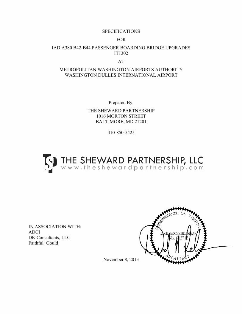
DOCUMENT 000010 - TABLE OF CONTENTS
DIVISION 00 – PROCUREMENT AND CONTRACTING REQUIREMENTS
00 00 10 Table of Contents
00 73 00 Supplementary Conditions
DIVISION 01 – GENERAL REQUIREMENTS
01 10 00 Summary
01 22 00 Unit Prices
01 22 10 Measurement and Payment
01 29 00 Application for Payment
01 31 00 Project Management and Coordination
01 33 00 Submittals
01 40 00 Quality Requirements
01 71 13 Mobilization/ Demobilization
01 71 14 Maintenance and Protection of Traffic During Construction
01 77 00 Project Closeout
01 78 39 Project Record Documentation
TECHNICAL SPECIFICATIONS:
DIVISION 02 – EXISTING CONDITIONS
Not Used
DIVISION 03 – CONCRETE
Not Used
DIVISION 04 – MASONRY
Not Used
DIVISION 05 – METALS
Not Used
DIVISION 06 – WOOD, PLASTICS, AND COMPOSITES
06 10 00 Rough Carpentry
DIVISION 07 – THERMAL AND MOISTURE PROTECTION
Not Used
WASHINGTON DULLES INTERNATIONAL AIRPORT IAD IT1302
A380 B42/44 PASSENGER BOARDING BRIDGE UPGRADES NOVEMBER 8, 2013
SPECIFICATIONS TOC 000010 - 2
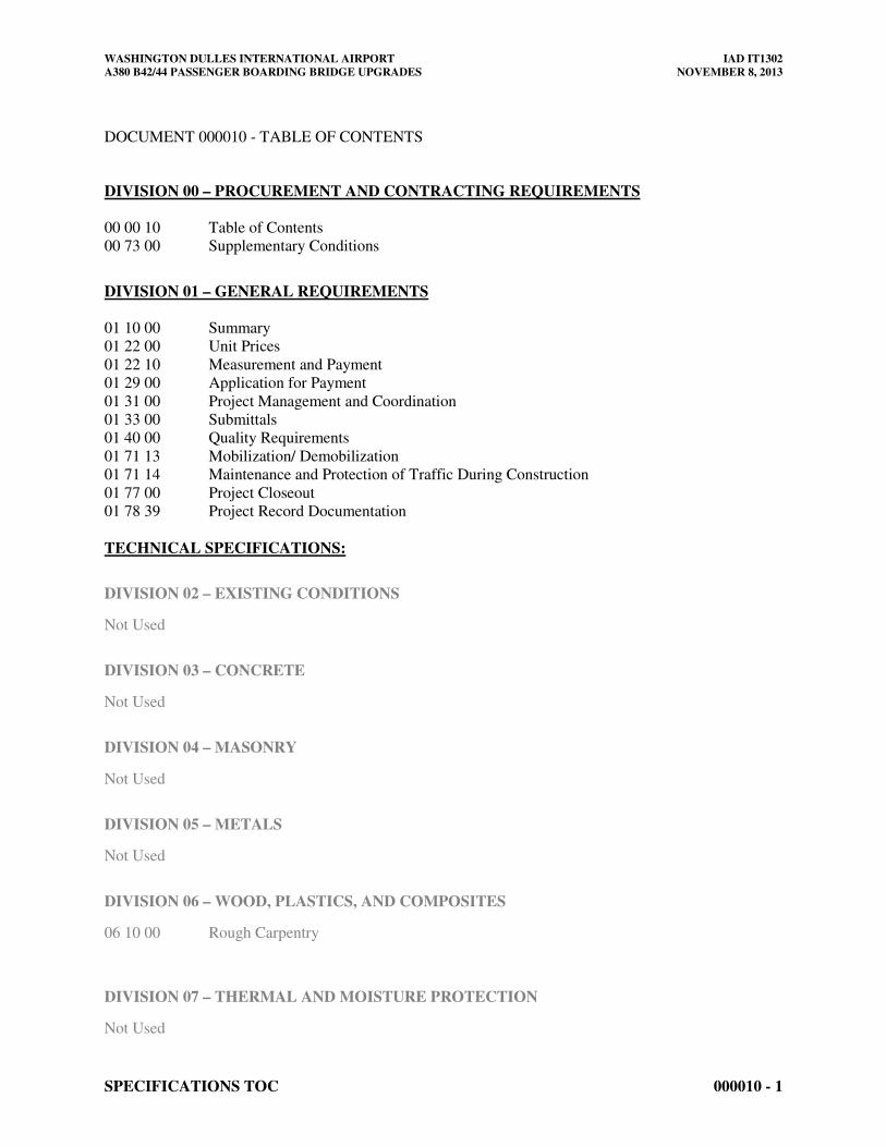
DIVISION 08 – OPENINGS
Not Used
DIVISION 09 – FINISHES
Not used
DIVISION 10 – SPECIALTIES
Not Used
DIVISION 11 – EQUIPMENT
Not Used
DIVISION 12 – FURNISHINGS
Not Used
DIVISION 13 – SPECIAL CONSTRUCTION
Not Used
DIVISION 14 – CONVEYING EQUIPMENT
Not Used
DIVISION 21 – FIRE SUPPRESSION
Not Used
DIVISION 22 – PLUMBING
Not Used
DIVISION 23 – HEATING VENTILATING AND AIR CONDITIONING
23 81 21 Preconditioned Air Unit and Accessories
DIVISION 25 – INTERGRATED AUTOMATION
Not Used
DIVISION 26 – ELECTRICAL
WASHINGTON DULLES INTERNATIONAL AIRPORT IAD IT1302
A380 B42/44 PASSENGER BOARDING BRIDGE UPGRADES NOVEMBER 8, 2013
SPECIFICATIONS TOC 000010 - 3
26 35 43 Ground Power Units and Accessories
DIVISION 27 – COMMUNICATIONS
Not Used
DIVISION 28 – ELECTRONIC SAFETY AND SECURITY
Not Used
DIVISION 31 – EARTHWORK
Not Used
DIVISION 32 – EXTERIOR IMPROVEMENTS
Not Used
DIVISION 33 – UTILITIES
Not Used
DIVISION 34 – TRANSPORTATION
34 77 13 Passenger Boarding Bridges
APPENDIX I – DRAWINGS AND SKETCHES
CV03.001 Final Conditions and Fleet Mix Plan – For Reference Only
CV03.002 Elevation Plan – For Reference Only
ST00.0001 PBB Structural Specifications and Anchor Bolt Layout
APPENDIX II –ADDITIONAL DOG LEG REQUIREMENTS
Photographs and notations for additional Dog Leg Requirements
END OF DOCUMENT 000010
WASHINGTON DULLES INTERNATIONAL AIRPORT IAD IT1302
A380 B42/44 PASSENGER BOARDING BRIDGE UPGRADES NOVEMBER 8, 2013
SPECIFICATIONS TOC 000010 - 4
THIS PAGE INTENTIONALLY LEFT BLANK
WASHINGTON DULLES INTERNATIONAL AIRPORT IAD IT1302
A380 B42/44 PASSENGER BOARDING BRIDGE UPGRADES NOVEMBER 8, 2013
SUPPLEMENTARY CONDITIONS 007300 - 1
SECTION 007300 SUPPLEMENTARY CONDITIONS
PART 1 - GENERAL
1.1 RELATED DOCUMENTS
A. Drawings, Contract Provisions, Special Provisions, and other Division 01 Specification
Sections, apply to this Section.
1.2 SUMMARY
A. The articles and paragraphs of this Section represent supplements or additions to the Contract
Provisions or the Special Provisions. Use is only anticipated for delivery of material.
1.3 WORK UNDER OTHER CONTRACTS
A. During the period of this Project, the Authority anticipates that other construction contracts
may be underway at or near the site of work of this Contract. Coordination with other
contractors would be required to minimize any impacts on airport operations.
1.4 MAINTENANCE OF PEDESTRIAN AND VEHICULAR TRAFFIC
Does not apply.
1.5 AIRFIELD AND TERMINAL BUILDING OPERATIONAL REQUIREMENTS
A. None anticipated.
1.6 ENVIRONMENTAL PROTECTION
A. Comply with all Federal, state and local laws and regulations controlling pollution of the
environment. Take necessary precautions to prevent pollution of streams, rivers, lakes, ponds,
and reservoirs with fuels, oils, bitumens, chemicals, or other harmful materials and to prevent
pollution of the atmosphere from particulate and gaseous matter.
B. Notify COTR immediately in the event that abnormalities, discolorations, odors, oil, or other
signs of potential contamination by hazardous materials are encountered during excavation or
other construction activities. Follow with written notice within 24 hours, indicating date,
time, and location of potential contaminants encountered. The COTR will provide further
direction to Contractor regarding disposition of materials encountered.
WASHINGTON DULLES INTERNATIONAL AIRPORT IAD IT1302
A380 B42/44 PASSENGER BOARDING BRIDGE UPGRADES NOVEMBER 8, 2013
SUPPLEMENTARY CONDITIONS 007300 - 2
1.7 ARCHAEOLOGICAL AND HISTORICAL FINDINGS
A. Notify immediately, through the COTR, the PMC Archaeology/Historic Preservation
Coordinator if subsurface structural features, concentrations of artifacts, rubble, bone/shell, or
burnt material are uncovered or otherwise discovered. Prompt reporting will avoid potentially
severe problems resulting from the destruction of significant resources and may limit the
impact on construction operations and schedules.
1.8 DAMAGES AND PRE-EXISTING CONDITIONS
A. Be responsible for all damages caused by Contractor’s construction activities. Provide all
labor, materials, etc. to return any damaged areas, systems or equipment to their original
condition at no additional cost to the Authority.
B. Perform a survey of pre-existing conditions in the vicinity of Contractor’s construction
activities, utilizing photographs and other means as necessary to document existing damage or
conditions. Submit two copies of this survey to the Contracting Officer within 21 calendar
days after Notice-to-Proceed. This survey will assist in resolving any damage claims against
the Contractor during and after construction.
1.9 SECURITY DURING CONSTRUCTION
A. Maintain the integrity of any Airport Security fence. Maintain the integrity of doors and walls
between public areas and Air Operations Area (AOA) at all times. Comply with Title 49
Code of Federal Regulations, Parts 1500, 1540, 1542 and 1544.
B. Possession of and display of a proper and current Airport Identification Badge, issued by
Airport Operations is required for all Contractor personnel passing into the AOA. Refer to
"Airport Orders and Instructions" attached as part of the Contract for specific requirements.
Security requirements have increased significantly at Washington Dulles International Airport
and Contractor can expect possible short delays clearing construction vehicles into the AOA.
Offerors shall become intimately familiar with all TSA and Authority security requirements.
No increase in contract price will be provided to the Contractor should the contractor not be
aware of any security procedure in place at time of submitting their offer that leads to
increased time and inconvenience to accomplish the work.
C. Pay all fines levied by the appropriate authorities for penalties resulting from security
infractions perpetrated by or caused by Contractor’s personnel or work forces of Contractor’s
subcontractors or suppliers.
D. Establish and maintain the security of Contractor’s staging areas, equipment and materials.
E. Provide escort for delivery vehicles transporting materials and supplies to or from the
Contractor's staging or work areas into the AOA, in accordance with requirements stated in
"Airport Orders and Instructions" attached as part of the Contract.
F. Do not park within 300 feet of a terminal building unless specifically authorized by Airport
Operations.
WASHINGTON DULLES INTERNATIONAL AIRPORT IAD IT1302
A380 B42/44 PASSENGER BOARDING BRIDGE UPGRADES NOVEMBER 8, 2013
SUPPLEMENTARY CONDITIONS 007300 - 3
G. No firearms or weapons of any type are allowed on the airport.
H. No cartridge style nail guns, nor any tools that use a cartridge or any explosive charge, are
allowed without prior written notification of COTR. Obtain written approval from the COTR
before bringing such tools on the project.
I. Conform to all Orders and Instructions pertaining to vehicle inspection.
1.10 MATERIAL HAULING
A. Access and egress to and from the Airport for hauling operations shall be through the
entrances indicated. Conduct hauling operations during working hours and as indicated on the
drawings.
B. Contractor shall use the haul routes for this project as indicated on the drawings and as
designated by the COTR.
C. Submit a detailed Work Plan for Contractor’s entire operations to the COTR for approval
prior to commencing work. Obtain written approval from the COTR of the Work Plan.
Identify clearly on Work Plan each operation requiring coordination with Airport Operations.
1. For taxiway closures of short duration, provide flagmen, with radio contact with the FAA
Airport Traffic Control Tower and the Authority Ramp Control Tower, at taxiway
crossing intersections. COTR will determine the number of flagmen required.
2. For long-term taxiway closures, clearly mark, light, and barricade the taxiway closures
and haul routes in accordance with FAA and Airport Operations requirements.
D. Provide advance notice to the COTR, as required in the drawings, of any scheduled taxiway,
or taxi lane closures. Obtain the written approval of the Authority prior to closing or crossing
a taxiway or taxi lane.
E. Use load covers on all dump trucks. Load dump trucks so that no spillage occurs during
transit on the State, municipal, or Airport roadways, taxiways, and aprons. Clean wheels of
trucks leaving the Project construction site of all soil and rocks.
F. Be responsible for the cost of the immediate cleaning of earth tracking and spills on paved
surfaces resulting from the Contractor's operations. Because of the potential for extreme
damage to aircraft engines due to the ingestion of foreign objects, maintain on the project
mechanical sweeper/vacuum (wet/dry) equipment with nylon brushes complete with
operators. Maintain a water truck on site at all times in order to effectively control dust rising
from construction activities. Requirement for the sweeper/vacuum truck and water truck will
apply during any earthwork/grading operations.
G. Provide sweeper/vacuum equipment with a usable hopper capacity of 6 cubic yards and with a
regenerative air capacity of 15,000 CFM. Provide equipment with gutter brooms of poly
brush material so as not to damage airfield pavement markings; a dust control system that
includes an external spray system with front mounted spray bar, nozzles located at each gutter
broom; and an internal spray system with nozzles in the internal air stream. Maintain the
WASHINGTON DULLES INTERNATIONAL AIRPORT IAD IT1302
A380 B42/44 PASSENGER BOARDING BRIDGE UPGRADES NOVEMBER 8, 2013
SUPPLEMENTARY CONDITIONS 007300 - 4
equipment in good working order throughout the project and replace the brooms and or spray
systems, as necessary, to ensure proper sweeping and vacuuming of paved surfaces.
1.11 PORTABLE LIGHTING
A. Contractor shall be responsible for portable lighting for all night-work or early morning work.
Portable lighting shall be in accordance with the Authority design manual and must be
approved by the COTR.
B. Portable lighting: If used for Contractor operations, aim and shield portable lighting at all
times to eliminate glare that could impair runway, taxiway, apron, ground operations, and
Airport Traffic Control Tower operations. Equip portable lighting with reflectors and glare
shields to prevent spillover of light into operational areas.
1.12 RADIO COMMUNICATIONS
A. If Contractor’s personnel use two-way radio communication on the job site, submit proposed
frequencies to COTR for approval in writing by the COTR. Frequencies shall not conflict
with or overlay any of the Airports radio frequencies.
B. Provide, at a minimum, the following with radio equipment: The Project Superintendent,
Foreman of all work groups physically separated from the general vicinity of the Project
Superintendent, gate guards, and others who may be working in a separate and remote area.
C. Provide two-way radios capable of operating on both the "Ground" and "Ramp" frequencies
for work adjacent to or affecting taxiways, Mobile Lounge roads, or Mobile Lounge docking
areas. Such radios shall be either a handheld programmable type capable of operating off of
vehicle power and antenna or a vehicle-mounted type, which operates solely off of the
vehicle’s power, and antenna. Provide radios that provide a minimum of 3 watts transmitting
power. Provide radios of sufficient power to communicate with the appropriate controller.
1.13 Not used.
1.14 SAFETY
A. Comply with all requirements set forth in the most current edition of the Authority
Construction Safety Manual”. Offerors are provided with the most recent addition when
obtaining contract documents prior to proposal. Requirements included in this Section are in
addition to the Authority’s Construction Safety Manual. Comply with all local, State and
Federal requirements. Where conflicts or discrepancies exist between requirements, the more
stringent requirement shall govern. For additional information see Division 01 Section
“Quality Requirements”.
B. Contractor Safety Organization:
1. Safety Engineer.
a. Duties: Outlined in The Authority Construction Safety Manual.
WASHINGTON DULLES INTERNATIONAL AIRPORT IAD IT1302
A380 B42/44 PASSENGER BOARDING BRIDGE UPGRADES NOVEMBER 8, 2013
SUPPLEMENTARY CONDITIONS 007300 - 5
b. Qualifications: Outlined in The Authority Construction Safety Manual.
C. Submit the résumés of individuals proposed to serve in the role of Contractor’s Safety
Engineer to the COTR for approval in writing. If qualified, Contractor’s Superintendent or
Foreman will be allowed to serve the role of Safety Engineer. In addition to indicating the
qualifications in the Authority Construction Safety Manual résumés shall include but not be
limited to such items as: work experience, education, safety and health training completed,
memberships in professional associations, professional certifications, professional
registrations and professional references confirming the qualifications and personal references
of contacts for verification shall also be required.
D. Provide safe and healthful working conditions on each operation at all times during execution
the work of this Contract. Conduct the various operations connected with the Work so that
they will not be injurious to safety or health. Comply with all provisions, regulations and
recommendations issued pursuant to the Occupational Safety and Health Act of 1970 and the
Construction Safety Act of 1969, as well as amendments to these laws. Comply with laws,
rules and regulations of other authorities having jurisdiction, with regard to all matters relating
to the safety and health of workers and the general public. Compliance with government
requirements is mandated by law and considered only a minimum level of safety performance.
Perform all work in accordance with best safe work practices recognized by the construction
industry. Stop work whenever a work procedure or a condition at a work site is deemed unsafe
by the either of the following individuals: COTR, Program Safety Manager (PSM), the
Contractor’s Project Manager, the Contractor’s Foreman or the Contractor’s Safety
Engineer(s).
E. Provide the services of responsible safety personnel per construction work shift for the
duration of this Contract. The Safety personnel shall be responsible for all safety and health
requirements as included herein and as required by the Authority’s Construction Safety
Manual.
F. Comply with all requirements set forth in the Authority's "Construction Safety Manual."
Provide during the Work the services of Safety Engineer(s) as outlined in the Authority’s
“Construction Safety Manual” and in Division 01 Section “Quality Requirements”. The
Safety Engineer shall undertake the duties and responsibilities as stated in the Authority's
"Construction Safety Manual”.
G. Prior to start of construction activities in the Air Operations Area (AOA), the Contractor's
Safety Engineers shall tour the AOA with the Authority Safety Program Manager.
H. Flagmen Training: The Authority will sponsor Flagman training sessions. Contractor's
personnel who will be assigned flagmen duties on the Airport for this project shall attend
training sessions.
I. Fire Safety: Conform to the following requirements:
1. Obtain a permit to perform any welding, cutting, or hot work from the Office of the
Authority Fire Marshal.
2. Ensure adequate access to all construction areas for emergency response.
3. Obtain a permit from the Office of the Authority Fire Marshal to store, handle, or use any
hazardous material, including but not limited to fuels for equipment. Complete an
application prior to issuance.
WASHINGTON DULLES INTERNATIONAL AIRPORT IAD IT1302
A380 B42/44 PASSENGER BOARDING BRIDGE UPGRADES NOVEMBER 8, 2013
SUPPLEMENTARY CONDITIONS 007300 - 6
4. Remove combustible debris from the site daily.
5. Provide at least seven (7) days notice for any request for inspections, tests, permits, etc.,
required of personnel from the Office of the Authority Fire Marshal.
6. Obtain a permit from the Office of the Authority Fire Marshal for the use, storage or
handling of any explosives.
7. Provide to the Office of the Authority Fire Marshal a list of emergency contact numbers
for the COTR and the Contractor prior to the commencement of Work.
J. Submit Site-Specific Safety and Health Plans to COTR within 15 calendar days of Notice to
Proceed and prior to the start of any construction activities. Prepare this plan using the
Authority’s Guidelines as defined in the Authority’s “Construction Safety Manual” and as
supplemented by these specifications for each and every work zone as shown on the drawings
or as anticipated by the Contractor. COTR must approve the Site-Specific Safety Plan prior to
the start of any work.
K. Be responsible for the safe operation of all job site motor vehicles. Provide a “spotter” or
flagman for all backing operations of construction vehicles with restricted rear vision.
L. All motorized equipment and vehicles working on or entering MWAA construction project
work areas shall be equipped with functional audible backup alarms.
M. Crane Operators. Crane use not anticipated.
N. For all airside projects attach a Safety Plan to the Safety Program. Include in the Safety Plan,
to the extent applicable, provisions for the following:
1. Scope of work performed by Contractor, including proposed duration of work.
2. Job Hazard Analysis Program.
3. Work control measures.
4. Limitations on equipment height.
5. Location of airport operational areas.
6. Location of and access to stockpiled construction materials and equipment.
7. Inspection requirements.
8. Trenches and excavations, and cover requirements.
9. Vehicle operation and pedestrian access in airport movement areas.
10. Construction site access and haul roads, includes maintenance of and keeping open ARFF
access routes.
11. Limitations on construction.
12. Radio communications.
13. Foreign object debris (FOD) control provisions.
14. Hazardous materials (HAZMAT) management.
15. Wildlife abatement.
16. NOTAM issuance.
17. Vehicle identification.
18. Vehicle parking.
19. Use of temporary visual aids.
20. Obstacle-free zones (OFZ).
21. Approach clearance to runways.
22. Runway and taxiway safety areas.
23. Required compliance of contractor personnel.
24. Emergency notification for fire, medical, and police response.
WASHINGTON DULLES INTERNATIONAL AIRPORT IAD IT1302
A380 B42/44 PASSENGER BOARDING BRIDGE UPGRADES NOVEMBER 8, 2013
SUPPLEMENTARY CONDITIONS 007300 - 7
1.15 HEIGHT LIMITATION
A. For all construction within the Airport, limit the height of Contractor's equipment to a
maximum of 15 feet. For any work that requires equipment higher than 15 feet, Contractor
must request in writing COTR’s approval.
B. Prior to beginning any work coordinate with the COTR the height of all cranes, boom trucks,
scaffolds or similar vehicles of construction. Properly mark all construction equipment with
safety flags and warning lights in accordance with current FAA and Airport Operations
requirements.
1.16 NOISE CONTROL
Not applicable.
1.17 EXAMINATION OF PLANS, SPECIFICATIONS AND SITE OF WORK
A. The offeror is expected to examine carefully the site of the proposed work, the proposal,
plans, specifications, solicitation provisions, contract provisions, special provisions and
contract forms before submitting a proposal. The submission of a proposal will be considered
conclusive evidence that the offeror has made such examination and is satisfied as to the
conditions to be encountered in performing the work as to the requirements of the Contract.
1.18 AIRPORT SECURITY/VEHICLE INSPECTION PROCEDURE
A. Contractor access to the project site shall be as shown on the drawings.
B. The following procedures will be utilized for all escorted vehicles and AOA approved
vehicles with non-badged passengers seeking entry to the AOA:
1. All vehicles are searched.
2. Coordinate all vehicle deliveries with the COTR in advance. Provide the vehicle license
plate number and expected delivery time for all vehicle deliveries. Contractor may
compile the expected daily delivery schedule on one sheet for submission to the COTR.
3. The vehicle operator shall have in his or her possession a commercial manifest, which
identifies the contents of the vehicle and/or trailer.
4. An escort from the company for whom the shipment is intended shall respond to the
vehicle access gate and remain with the vehicle until the vehicle exits the secured area.
5. A vehicle search will be conducted and once cleared; vehicles will be permitted escorted
access to their delivery point.
6. Contractors should expect minor delays up at AOA gate as a result of these security
provisions.
7. Priority consideration may be offered to concrete trucks with resulting delays estimated to
be 20 minutes. To receive priority consideration, schedule concrete deliveries with
Airport Operations and COTR at time of batching.
C. Prior approval from the Manager of Airport Operations or his/her designated representative is
required for any exceptions to the above procedures.
WASHINGTON DULLES INTERNATIONAL AIRPORT IAD IT1302
A380 B42/44 PASSENGER BOARDING BRIDGE UPGRADES NOVEMBER 8, 2013
SUPPLEMENTARY CONDITIONS 007300 - 8
PART 2 - PRODUCTS (Not Used)
PART 3 - EXECUTION (Not Used)
END OF SECTION 007300
WASHINGTON DULLES INTERNATIONAL AIRPORT IAD IT1302
A380 B42/44 PASSENGER BOARDING BRIDGE UPGRADES NOVEMBER 8, 2013
SUMMARY 011000 - 1
SECTION 011000 SUMMARY
PART 1 - GENERAL
1.1 RELATED DOCUMENTS
A. Drawings, Contract Provisions, Special Provisions, Supplementary Conditions, and other
Division 01 Specification Sections apply to this Section.
1.2 SUMMARY
A. This Section includes the following:
1. Work covered by the Contract Documents.
2. Type of the Contract.
3. Work phases.
4. Work under other contracts.
5. Use of premises.
6. Work restrictions.
7. Specification formats and conventions.
B. Related Sections include the following:
1. None.
1.3 WORK COVERED BY CONTRACT DOCUMENTS
A. Project Identification: IA1302 – Project consists of fabrication of two new passenger boarding
bridges to service the A380 and additional fleet mix of aircraft utilized at Washington Dulles
International airport. The bridges will be delivered on-site in the designated staging area and
released to the Authority. Installation will be performed by others.
B. Architect/Engineer Identification: The Final Submission Documents, dated November 8, 2013
were prepared for the Project by The Sheward Partnership and sub-consultants.
1.4 TYPE OF CONTRACT
A. Project will be constructed under a general construction contract.
1.5 WORK PHASES
A. Conduct the Work in accordance with the phases and restrictions shown on the plans.
WASHINGTON DULLES INTERNATIONAL AIRPORT IAD IT1302
A380 B42/44 PASSENGER BOARDING BRIDGE UPGRADES NOVEMBER 8, 2013
SUMMARY 011000 - 2
B. The installation and sequence will be done by others. Contractor will coordinate with the COTR
for any requirements on timing for installation and acceptance.
C. Before commencing fabrication, submit a schedule to COTR showing the sequence, the
commencement and completion and deliver dates.
D. Contractor is required to meet with COTR 30 calendar days prior to the start of fabrication
activities.
1.6 WORK UNDER OTHER CONTRACTS
A. General: Cooperate fully with separate contractors so work on those contracts may be carried
out smoothly, without interfering with or delaying work under this Contract. Coordinate the
Work of this Contract with work performed under separate contracts.
B. A separate contractor and project will be concurrent with the activities of this project. The
General Contractor for the Facility Modifications project will be working with the COTR for
installation of the material provided.
1.7 USE OF PREMISES
A. Use of Site: Limit use of premises to work in areas indicated. Do not disturb portions of site
beyond areas in which the Work is indicated.
1. Limits: Confine constructions operations to the project site shown on the plans.
2. Authority Occupancy: Allow for Authority occupancy of site and day-to-day use by
tenants, and air carriers.
3. Contractor shall have full use of premises for construction operations within the Contract
Limit Lines indicated during construction period, during the hours indicated, and as
directed by COTR. Contractor's use of premises is limited only by the Authority's right
to perform work or to retain other contractors on portions of Project.
4. Driveways and Entrances: Keep driveways and entrances serving premises clear and
available to the Authority, the Authority's employees, tenants, air carriers, and emergency
vehicles at all times. Do not use driveways and entrances for parking or storage of
materials.
a. Schedule deliveries to minimize use of driveways and entrances.
b. Schedule deliveries to minimize space and time requirements for storage of
materials and equipment on-site.
B. Utilize areas designated for Contractor staging, storage, and parking, as indicated. For
additional requirements, see Section "Supplementary Conditions."
WASHINGTON DULLES INTERNATIONAL AIRPORT IAD IT1302
A380 B42/44 PASSENGER BOARDING BRIDGE UPGRADES NOVEMBER 8, 2013
SUMMARY 011000 - 3
1.8 CONTRACTOR HOURS OF OPERATION
A. Contractor Working Hours: Work shall be performed during any hours as fabrication is off-site.
1.9 SPECIFICATION FORMATS AND CONVENTIONS
A. Specification Format: With the exception of Federal Aviation Administration (FAA) standard
specifications and Virginia Department of Transportation standard specifications the
Specifications are organized into Divisions and Sections using the 33-Division format using the
CSI/CSC's "MasterFormat ‘04" numbering system.
1. Section Identification: The Specifications use Section titles to help with cross-
referencing in the Contract Documents. Sections in the Project Manual are in numeric
sequence; however, the sequence is incomplete as all available Sections and Section
numbers are not used and the CSI numbering system is not sequentially complete.
Consult the table of contents at the beginning of the Project Manual to determine
numbers and names of sections in the Contract Documents.
B. Specification Content: The Specifications use certain conventions for the style of language and
the intended meaning of certain terms, words, and phrases when used in particular situations.
These conventions are as follows:
1. Abbreviated Language: Language used in the Specifications and other Contract
Documents is abbreviated. Interpret words and meanings as appropriate. Infer words
implied, but not stated, as the sense requires. Interpret singular words as plural, and
plural words as singular where applicable as the context of the Contract Documents
indicates.
2. Imperative mood and streamlined language are used in these Specifications. This
imperative language is directed to the Contractor, unless specifically noted otherwise.
Requirements expressed in the imperative mood are to be performed by Contractor.
Occasionally, the indicative or subjunctive mood may be used in the Section Text for
clarity to describe responsibilities that must be fulfilled indirectly by Contractor or by
others when so noted.
a. The words "shall," "shall be," or "shall comply with," depending on the context,
are implied where a colon (:) is used within a sentence or phrase.
1.10 MARKING UTILITY SERVICES
A. None anticipated.
1.11 UTILITY OUTAGES
None anticipated.
WASHINGTON DULLES INTERNATIONAL AIRPORT IAD IT1302
A380 B42/44 PASSENGER BOARDING BRIDGE UPGRADES NOVEMBER 8, 2013
SUMMARY 011000 - 4
PART 2 - PRODUCTS (Not Used)
PART 3 - EXECUTION (Not Used)
END OF SECTION 011000
WASHINGTON DULLES INTERNATIONAL AIRPORT IAD IT1302
A380 B42/44 PASSENGER BOARDING BRIDGE UPGRADES NOVEMBER 8, 2013
UNIT PRICES 012200 - 1
SECTION 012200 UNIT PRICES
PART 1 - GENERAL
1.1 RELATED DOCUMENTS
A. Drawings, Contract Provisions, Special Provisions, Supplementary Conditions, and other
Division 01 Specification Sections apply to this Section.
1.2 SUMMARY
A. This Section includes administrative and procedural requirements for unit prices.
B. Related Sections include the following:
1. Division 01 Section "Measurement and Payment" for procedures for measurement and
payment for unit-price items.
1.3 DEFINITIONS
A. A unit price is an amount proposed by offerors and stated on the Schedule as a price per unit of
measurement for materials or services. An estimate of the quantities of work to be done and
materials to be furnished under these specifications is given in Section III, "Schedule." It is
given only as a basis for comparison of proposals and the award of the Contract. The Authority
does not expressly or by implication agree that the actual quantities involved will correspond
exactly therewith; nor shall Contractor plead misunderstanding or deception because of such
estimates of quantities, or of the character, location, or other conditions pertaining to the work.
Payment to Contractor will be made only for the actual quantities of work performed or
materials furnished according to the plans and specifications.
1.4 PROCEDURES
A. Unit prices include all necessary material, plus cost for delivery, installation, insurance,
applicable taxes, overhead, and profit. The sum of all extended unit prices in the Section III,
"Schedule," shall be deemed to include all work described in the Contract Documents including
Drawings and Specifications.
B. Measurement and Payment: Refer to individual Specification Sections for work that requires
establishment of` unit prices. Methods of measurement and payment for unit prices are
specified in those Sections and in Division 01 Section "Measurement and Payment."
C. The Authority reserves the right to reject Contractor's measurement of work-in-place that
involves use of established unit prices and to have this work measured, at the Authority's
expense, by an independent surveyor acceptable to Contractor.
WASHINGTON DULLES INTERNATIONAL AIRPORT IAD IT1302
A380 B42/44 PASSENGER BOARDING BRIDGE UPGRADES NOVEMBER 8, 2013
UNIT PRICES 012200 - 2
PART 2 - PRODUCTS (Not Used)
PART 3 - EXECUTION (Not Used)
END OF SECTION 012200
WASHINGTON DULLES INTERNATIONAL AIRPORT IAD IT1302
A380 B42/44 PASSENGER BOARDING BRIDGE UPGRADES NOVEMBER 8, 2013
MEASUREMENT AND PAYMENT 012210 - 1
SECTION 012210 MEASUREMENT AND PAYMENT
PART 1 - GENERAL
1.1 RELATED DOCUMENTS
A. Drawings, Contract Provisions, Special Provisions, Supplementary Conditions, and other
Division 01 Specification Sections apply to this Section.
1.2 SUMMARY
A. This Section includes administrative and procedural requirements governing methods of
measurement and computations to be used in determination of quantities of material furnished
and unit amount of Work performed under the Contract in order for Contractor to receive
payment according to pre-established unit prices.
B. At the discretion of the COTR, payment may be reduced for any Work which is not in full
compliance with the Contract Documents or which has been damaged or repaired by Contractor.
Such action may be used when the end product may have a reduced service life or less than
desirable aesthetic characteristics.
1.3 MEASUREMENT OF QUANITITES
Measurement of quantities on this contract is as specified in the Technical Specifications.
1.4 SCALES
Not used.
1.5 PAYMENT FOR MATERIALS ON HAND
Not used.
PART 2 - PRODUCTS (Not Used)
PART 3 - EXECUTION (Not Used)
END OF SECTION 012210
WASHINGTON DULLES INTERNATIONAL AIRPORT IAD IT1302
A380 B42/44 PASSENGER BOARDING BRIDGE UPGRADES NOVEMBER 8, 2013
MEASUREMENT AND PAYMENT 012210 - 2
THIS PAGE INTENTIONALLY LEFT BLANK
WASHINGTON DULLES INTERNATIONAL AIRPORT IAD IT1302
A380 B42/44 PASSENGER BOARDING BRIDGE UPGRADES NOVEMBER 8, 2013
APPLICATION FOR PAYMENT 012900 - 1
SECTION 012900 – APPLICATION FOR PAYMENT
PART 1 - GENERAL
1.1 RELATED DOCUMENTS
A. Drawings, Contract Provisions, Special Provisions, Supplementary Conditions, and other
Division 01 Specification Sections apply to this Section.
1.2 SUMMARY
A. This Section specifies administrative and procedural requirements necessary to prepare and
process Applications for Payment.
1. Coordinate the Schedule of Values and Applications for Payment with List of
Subcontracts, and Submittal Log.
B. Related Sections include the following:
1. Division 01 Section "Unit Prices" for administrative requirements governing use of unit
prices.
2. Division 01 Section "Measurement and Payment" for administrative requirements
governing methods of measurement and determination of quantities of materials for use
with unit prices.
3. Division 01 Section "Construction Progress Documentation" for administrative
requirements governing preparation and submittal of Contractor's Construction Schedule
and Submittals Schedule.
4. Division 01 Section “Project Closeout” for submittal of items required before final
payment.
5. Division 01 Section “Project Record Documents” for procedural requirements governing
the submission of Project Record Documents.
1.3 DEFINITIONS
Not used.
1.4 SCHEDULE OF VALUES
Not used.
1.5 APPLICATION FOR PAYMENT
A. Each Application for Payment shall be consistent with previous applications and payments as
certified by Contracting Officer and paid for by the Authority.
WASHINGTON DULLES INTERNATIONAL AIRPORT IAD IT1302
A380 B42/44 PASSENGER BOARDING BRIDGE UPGRADES NOVEMBER 8, 2013
APPLICATION FOR PAYMENT 012900 - 2
1. Initial Application for Payment, Application for Payment at time of Substantial
Completion, and final Application for Payment involve additional requirements.
B. Payment Application Times: Application for Payment shall coincide with the schedule monthly
update, or as otherwise indicated in the Agreement between the Authority and Contractor. The
period covered by each Application for Payment starts on the day following the end of the
preceding period and shall not exceed one calendar month, unless otherwise approved by
COTR.
C. Payment Application Forms: Use forms provided by the Contracting Officer, but supplied by
COTR, for Application for Payment.
D. Application Preparation: Complete every entry on form. Notarize and execute by a person
authorized to sign legal documents on behalf of Contractor. The Authority will return
incomplete applications without action.
1. Include amounts of Contract Modifications issued before last day of construction period
covered by application.
E. Transmittal: Submit one original and four copies of Application for Payment to the address
provided by the Contracting Officer, each one signed and notarized. Include waivers of lien and
similar attachments if required.
1. Transmit Applications for Payment with a transmittal form listing attachments and
recording appropriate information about application in a manner acceptable to Contracting
Officer.
F. Waivers of Mechanic's Lien: With Final Application for Payment, submit waivers of
mechanic's liens from subcontractors, sub-subcontractors, and suppliers.
1. The Authority reserves the right to designate which entities involved in the Work must
submit waivers.
2. Waiver Forms: Submit waivers of lien on forms, executed in a manner acceptable to the
Authority.
G. Initial Application for Payment: Administrative actions and submittals that shall precede or
coincide with submittal of first Application for Payment include the following:
1. List of subcontractors.
2. Contractor's Construction Schedule (preliminary if not final).
3. Products list.
4. Submittals Schedule (preliminary if not final).
5. Copies of authorizations and licenses from authorities having jurisdiction for performance
of the Work.
6. Performance and payment bonds.
7. Subcontractor Payment Form
H. Monthly Application for Payment: Administrative actions and submittals that shall accompany
the submittal of Contractor's monthly Application for Payment include the following:
WASHINGTON DULLES INTERNATIONAL AIRPORT IAD IT1302
A380 B42/44 PASSENGER BOARDING BRIDGE UPGRADES NOVEMBER 8, 2013
APPLICATION FOR PAYMENT 012900 - 3
1. Subcontractor Payment Form.
2. Monthly Progress Report, prepared according to requirements specified in Division 01
Section "Construction Progress Documentation."
3. Updated Inspection Control Log. Highlight changes from previous month.
4. Update of Contract Record Documents.
I. Application for Payment at Substantial Completion: After issuance of the Certificate of
Substantial Completion, submit an Application for Payment showing 100 percent completion
for portion of the Work claimed as substantially complete.
1. Include documentation supporting claim that the Work is substantially complete and a
statement showing an accounting of changes to the Contract Price.
2. This application shall reflect Certificates of Partial Substantial Completion issued
previously for Authority occupancy of designated portions of the Work, if applicable.
3. Advise COTR of change-over in security provisions.
J. Final Payment Application: Submit final Application for Payment with releases and supporting
documentation not previously submitted and accepted, including, but not limited, to the
following:
1. Evidence of completion of Project closeout requirements.
2. Insurance certificates for products and completed operations where required and proof
that taxes, fees, and similar obligations were paid.
3. Updated final statement, accounting for final changes to the Contract Price.
4. Evidence that claims have been settled.
5. Final, liquidated damages settlement statement.
6. Return of all Airport identification badges and keys.
PART 2 - PRODUCTS (Not Used)
PART 3 - EXECUTION (Not Used)
END OF SECTION 012900
WASHINGTON DULLES INTERNATIONAL AIRPORT IAD IT1302
A380 B42/44 PASSENGER BOARDING BRIDGE UPGRADES NOVEMBER 8, 2013
APPLICATION FOR PAYMENT 012900 - 4
THIS PAGE INTENTIONALLY LEFT BLANK
WASHINGTON DULLES INTERNATIONAL AIRPORT IAD IT1302
A380 B42/44 PASSENGER BOARDING BRIDGE UPGRADES NOVEMBER 8, 2013
PROJECT MANAGEMENT AND COORDINATION 013100 - 1
SECTION 013100 PROJECT MANAGEMENT AND COORDINATION
PART 1 - GENERAL
1.1 RELATED DOCUMENTS
A. Drawings, Contract Provisions, Special Provisions, Supplementary Conditions, and other
Division 01 Specification Sections apply to this Section.
1.2 SUMMARY
A. This Section includes administrative provisions for coordinating construction operations on the
Project including, but not limited to the following:
1. General project coordination procedures.
2. Administrative and supervisory personnel.
3. Project meetings.
a. Pre-construction conference.
b. Progress meetings.
B. Related Sections include the following:
1. Division 01 Section: "Execution" for the coordination of general installation and field-
engineering services.
2. Division 01 Section "Project Closeout" for coordinating Contract closeout.
1.3 COORDINATION
A. Coordination: Coordinate construction operations included in various Sections of the
Specifications to ensure efficient and orderly installation of each part of the Work. Coordinate
construction operations, included in different Sections that depend on each other for proper
execution of work.
B. Prepare memoranda for distribution to each party involved, outlining special procedures
required for coordination. Include such items as required notices, reports, and list of attendees
at meetings.
C. Administrative Procedures: Coordinate scheduling and timing of required administrative
procedures with other construction activities and activities of other contractors to avoid conflicts
and to ensure orderly progress of the Work and completion within the specified Contract
duration. Such administrative activities include, but are not limited to, the following:
1. Preparation of Contractor's Construction Schedule.
2. Delivery and processing of submittals.
3. Progress meetings.
4. Project closeout activities.
WASHINGTON DULLES INTERNATIONAL AIRPORT IAD IT1302
A380 B42/44 PASSENGER BOARDING BRIDGE UPGRADES NOVEMBER 8, 2013
PROJECT MANAGEMENT AND COORDINATION 013100 - 2
1.4 SUBMITTALS
A. Key Personnel Names: At the pre-construction meeting, submit a list of Contractor's key
personnel assignments. Key personnel shall include but not necessarily be limited to Project
Manager, Project Superintendent, Safety Manager, Quality Control Manager, Project Scheduler,
and other personnel in attendance at Project site along with alternates. Identify individuals and
their duties and responsibilities; list addresses and telephone numbers, including home and
office telephone numbers. Provide names, addresses, and telephone numbers of individuals
assigned as standbys in the absence of individuals assigned to Project.
1.5 REQUESTS FOR INFORMATION (RFIs)
A. Procedure: Immediately on discovery of the need for interpretation of the Contract Documents,
prepare and submit an RFI in the form specified.
1. RFIs shall originate with Contractor. RFIs submitted by entities other than Contractor
will be returned with no response.
2. Coordinate and submit RFIs in a prompt manner so as to avoid delays in Contractor's
work or work of subcontractors.
B. Content of the RFI: Include a detailed, legible description of item needing interpretation and
the following:
1. Contract Name
2. Contract Number
3. Date.
4. Name of Contractor.
5. Name of Resident Engineer
6. Name of Task Manager
7. RFI number, numbered sequentially.
8. Specification Section number and title and related paragraphs, as appropriate.
9. Drawing number and detail references, as appropriate.
10. Field dimensions and conditions, as appropriate.
11. Contractor's suggested solution(s). If Contractor's solution(s) impact the Contract Time
or the Contract Sum, Contractor shall state impact in the RFI.
12. Contractor's signature.
13. Attachments: Include drawings, descriptions, measurements, color photos, Product Data,
Shop Drawings, and other information necessary to fully describe items needing
interpretation.
a. Supplementary drawings prepared by Contractor shall include dimensions,
thicknesses, structural grid references, and details of affected materials,
assemblies, and attachments.
C. Software-Generated RFIs: Software-generated form with substantially the same content as
indicated above.
1. Attachments shall be electronic files in Adobe Acrobat PDF format.
2. RFI must be signed and scanned for electronic transmission.
3. Electronic copy RFI’s will be transmitted using the Authority provided Primavera Unifier
project management system.
WASHINGTON DULLES INTERNATIONAL AIRPORT IAD IT1302
A380 B42/44 PASSENGER BOARDING BRIDGE UPGRADES NOVEMBER 8, 2013
PROJECT MANAGEMENT AND COORDINATION 013100 - 3
D. COTR’s Action: COTR will review each RFI, determine action required, and return it. Allow
seven (7) working days for COTR's response for each RFI. RFIs received after 1:00 p.m. will
be considered as received the following working day.
1. The following RFIs will be returned without action:
a. Requests for approval of submittals.
b. Requests for approval of substitutions.
c. Requests for coordination information already indicated in the Contract
Documents.
d. Requests for adjustments in the Contract Time or the Contract Sum.
e. Requests for interpretation of Architect's actions on submittals.
f. Incomplete RFIs or RFIs with numerous errors.
2. COTR's action may include a request for additional information, in which case COTR's
time for response will start again.
3. COTR's action on RFIs that may result in a change to the Contract Time or the Contract
Sum may be eligible for Contractor to submit Change Proposal.
a. If Contractor believes the RFI response warrants change in the Contract Time or
the Contract Sum, notify COTR in writing within three (3) days of receipt of the
RFI response.
E. On receipt of COTR’s action, update the RFI log and immediately distribute the RFI response to
affected parties. Review response and notify COTR within three (3) days if Contractor
disagrees with response.
F. RFI Log: Prepare, maintain, and submit a tabular log of RFIs organized by the RFI number.
Submit log weekly prior to progress meeting for inclusion in progress meeting minutes. Include
the following:
1. Project name.
2. Name and address of Contractor.
3. Name of COTR.
4. RFI number including RFIs that were dropped and not submitted.
5. RFI description.
6. Date the RFI was submitted.
7. Date COTR’s response was received.
8. Identification of related Minor Change in the Work, Construction Change Directive, and
Proposal Request, as appropriate.
G. RFI Transmittal: The Contractor must use the Authority provided web-based Oracle Primavera
Unifier project management system (Unifier) to transmit each RFI to the COTR. Response of
the COTR’s RFI review and action will be transmitted to the Contractor through Unifier. The
Authority will provide the Contractor a Unifier license(s) and training.
1.6 SUPERVISORY PERSONNEL
A. General: In addition to Project Superintendent, provide other supervisory personnel as required
for proper performance of the Work.
WASHINGTON DULLES INTERNATIONAL AIRPORT IAD IT1302
A380 B42/44 PASSENGER BOARDING BRIDGE UPGRADES NOVEMBER 8, 2013
PROJECT MANAGEMENT AND COORDINATION 013100 - 4
1.7 PROJECT MEETINGS
A. Pre-construction Conference:
1. General: COTR will schedule pre-construction conference and organizational meeting
with Contractor after the Contracting Officer issues a notice of intent to award, or
actually awards the Contract. The meeting will review the parties' responsibilities and
personnel assignments.
a. Minutes: COTR will record and distribute meeting minutes to all attendees and
relevant parties.
2. Attendees: Contracting Officer, COTR, Engineer; Contractor and its superintendent;
major subcontractors; and other concerned parties. All participants at the conference
shall be familiar with Project and authorized to conclude matters relating to the Work.
3. Agenda: Discuss items of significance that could affect progress, including the
following:
a. Airport security.
b. LBDE/MBE/WBE/DBE participation and certifications.
c. Authority-controlled wrap-up insurance program.
d. Airport Operations coordination.
e. Preliminary construction schedule.
f. Phasing.
g. Critical work sequencing.
h. Designation of key personnel.
i. Procedures for processing field decisions and Contract Modifications.
j. Procedures for processing Applications for Payment.
k. Distribution of the Contract Documents.
l. Authority Construction guidelines.
m. Submittal procedures.
n. Preparation of Record Documents.
o. Use of the premises.
p. Responsibility for temporary facilities and controls.
q. Parking availability.
r. Office, work, and storage areas.
s. Equipment deliveries and priorities.
t. Safety procedures.
u. Quality-control requirements.
v. First aid.
w. Progress cleaning.
x. Working hours.
y. Authority Building Code requirements/permits.
4. Refer to Contract Provision "Pre-construction Requirements" for required submittals due
at the pre-construction conference.
WASHINGTON DULLES INTERNATIONAL AIRPORT IAD IT1302
A380 B42/44 PASSENGER BOARDING BRIDGE UPGRADES NOVEMBER 8, 2013
PROJECT MANAGEMENT AND COORDINATION 013100 - 5
B. Weekly Progress Meetings
1. General: COTR will conduct progress meetings weekly at regularly scheduled times
convenient for all parties involved. Additionally, discussions will address administrative
and technical issues of concern, determining resolutions, and development of deadlines
for resolution within allowable time frames.
a. Minutes: COTR will record and distribute meeting minutes.
2. Attendees: As may be required by COTR, in addition to representatives of the Authority
and Contractor, each subcontractor, and other entities concerned with current progress or
involved in planning, coordination, or performance of future activities. All participants at
the conference shall be familiar with Project and authorized to conclude matters relating
to the Work.
3. Agenda: Review and correct or approve minutes of previous progress meeting. Review
other items of significance that could affect progress. Include topics for discussion as
appropriate to status of Project.
a. Contractor's Construction Schedule: Review progress since the last meeting.
Determine whether each activity is on time, ahead of schedule, or behind schedule,
in relation to Contractor's Construction Schedule. Determine how construction
behind schedule will be expedited; secure commitments from parties involved to
do so. Discuss whether schedule revisions are required to ensure that current and
subsequent activities will be completed within the Contract Time.
b. Review present and future needs of each entity present, including the following:
1) Safety and Security.
2) Time.
3) Sequence of operations.
4) Status of submittals.
5) Deliveries.
6) Storage Areas
7) Access.
8) Requests for information.
9) Submittals.
10) Noncompliance notices.
11) Temporary facilities and controls.
12) Work hours.
13) Hazards and risks.
14) Progress cleaning.
15) Quality and work standards.
16) Contract Modifications.
17) Documentation of information for payment requests.
18) Preparation of Record Documents.
4. Submit at the weekly progress meeting, a two-week look-ahead schedule. This schedule
shall include a three-week period, one week showing actual progress from the previous
week and two weeks showing planned work for the two weeks after the meeting date.
Include in the schedule all activities in sufficient detail as approved by COTR. A two-
WASHINGTON DULLES INTERNATIONAL AIRPORT IAD IT1302
A380 B42/44 PASSENGER BOARDING BRIDGE UPGRADES NOVEMBER 8, 2013
PROJECT MANAGEMENT AND COORDINATION 013100 - 6
week look-ahead schedule form will be distributed at the pre-construction conference.
Submit a list of subcontractors identifying dates of when subcontractors will be on-site or
off-site. A form for this information will be provided by COTR.
5. Schedule Updating: Revise Contractor's Construction Schedule after each progress
meeting where revisions to the schedule have been made or recognized. Issue revised
schedule concurrently with the report of each meeting.
PART 2 - PRODUCTS (Not Used)
PART 3 - EXECUTION (Not Used)
END OF SECTION 013100
WASHINGTON DULLES INTERNATIONAL AIRPORT IAD IT1302
A380 B42/44 PASSENGER BOARDING BRIDGE UPGRADES NOVEMBER 8, 2013
SUBMITTALS 013300 - 1
SECTION 013300 SUBMITTALS
PART 1 - GENERAL
1.1 RELATED DOCUMENTS
A. Drawings, Contract Provisions, Special Provisions, Supplementary Conditions, and other
Division 01 Specification Sections apply to this Section.
1.2 SUMMARY
A. This Section includes administrative and procedural requirements for submitting Shop
Drawings, Product Data, Samples, and other miscellaneous submittals.
B. Related Sections include the following:
1. Division 01 Section "Project Closeout" for submitting warranties.
2. Division 01 Section "Project Record Documents" for submitting Record Drawings,
Record Specifications, and Record Product Data.
3. Technical Specifications for specific requirements for submittals in those Sections.
1.3 DEFINITIONS
A. Action Submittals: Written and graphic information that requires COTR's responsive action.
1.4 SUBMITTAL PROCEDURES
A. Submittals Schedule: Comply with requirements in Division 01 Section "Construction Progress
Documentation" for list of submittals and time requirements for scheduled performance of
related construction activities.
B. Contractor's Responsibilities: Contractor is responsible for the scheduling and submission of all
submittals. Submit to COTR all required Submittals. The COTR will forward submittals to the
appropriate parties for review.
C. Processing Time: Allow enough time for submittal review, including time for re-submittals, as
follows. Time for review shall commence on COTR’s receipt of submittal. No extension of the
Contract Time will be authorized because of failure to transmit submittals enough in advance of
the Work to permit processing, including re-submittals.
1. Initial Review: Allow 7 calendar days for initial review of each submittal. Allow
additional time if coordination with subsequent submittals is required. COTR will advise
Contractor when a submittal processed must be delayed for coordination.
2. Re-submittal Review: Allow 5 calendar days for review of each re-submittal.
3. No extension of the Contract Time will be authorized because of failure to transmit
submittals to COTR enough in advance of the Work to permit processing. Processing of
WASHINGTON DULLES INTERNATIONAL AIRPORT IAD IT1302
A380 B42/44 PASSENGER BOARDING BRIDGE UPGRADES NOVEMBER 8, 2013
SUBMITTALS 013300 - 2
incomplete or unacceptable submissions by COTR shall not reduce the number of
calendar days specified above for COTR's review.
4. Notations on submittals that increase the Contract cost or time of completion shall be
brought to COTR's attention before proceeding with the Work.
D. Identification: Place a permanent label or title block on each submittal for identification.
1. Indicate name of firm or entity that prepared each submittal on label or title block.
2. Provide a space approximately 6 by 8 inches on label or beside title block to record
Contractor's review and approval markings and action taken by COTR and Architect.
3. Include the following information on label for processing and recording action taken:
a. Contract name and number.
b. Date.
c. Name and address of Architect/Engineer.
d. Name and address of Contractor.
e. Name and address of subcontractor, if applicable.
f. Name and address of supplier, if applicable.
g. Name of manufacturer, if applicable.
h. Submittal number or other unique identifier, including revision identifier.
i. Alphanumeric project Identifier. Identifier is shown on the Project Drawings cover
sheet.
j. Number and title of appropriate Specification Section.
k. Drawing number and detail references, as appropriate.
l. Location(s) where product is to be installed, as appropriate.
m. Transmittal number.
E. Resubmissions: Re-submittal procedure shall follow the same procedures and same number as
the initial submittal with the following exceptions:
1. Transmittal shall contain the same information as the first transmittal and the submission
number shall indicate second, third, etc., submission. The drawing number/description
shall be identical to the initial submission and the date shall be the revised date for that
submission.
2. No new material shall be included on the same transmittal for a resubmission.
3. COTR rejection shall not warrant a claim by Contractor for additional time or cost.
F. Deviations: Highlight, encircle, or otherwise specifically identify deviations from the Contract
Documents on submittals. Where significant deviations from the Contract requirements exist,
follow the guidelines set forth in Division 01 Section "Product Requirements" for substitutions.
G. Transmittal: Package each submittal individually and appropriately for transmittal and
handling. Transmit each submittal from Contractor to COTR using the approved transmittal
form provided by COTR. COTR will return submittals, without review, received from sources
other than Contractor.
1. The Contractor must use the Authority provided web-based Oracle Primavera Unifier
project management system (Unifier) to transmit each RFI to the COTR. Response of the
COTR’s submittal review and action will be transmitted to the Contractor through
Unifier. The Authority will provide the Contractor a Unifier license(s) and training.
WASHINGTON DULLES INTERNATIONAL AIRPORT IAD IT1302
A380 B42/44 PASSENGER BOARDING BRIDGE UPGRADES NOVEMBER 8, 2013
SUBMITTALS 013300 - 3
H. Distribution: Provide 5 copies of each submittal.
I. Use for Construction: Use only final submittals with mark indicating “approved” by COTR in
connection with construction.
1.5 SUBMITTAL LOG
A. Prepare a log that contains a complete listing of all submittals required by Contract. Submit the
log at the preconstruction meeting along with Contractor's construction schedule specified in
Division 01 Section "Construction Progress Documentation." Organize the submittal log by
Section number. Assign each submittal a sequential number for identification and tracking
purposes.
1. Coordinate the submittal log with Division 01 Section "Construction Progress
Documentation." The submittal log shall be submitted for COTR's review. Include the
following information:
a. Title of submittal/description.
b. Submittal number (sequential).
c. Scheduled date for the first submittal.
d. Drawing number, if applicable.
e. Applicable Section number.
f. Name of subcontractor/vendor.
g. Scheduled date of COTR's final release or approval.
PART 2 - PRODUCTS
2.1 ACTION SUBMITTALS
A. General: Prepare and submit Action Submittals required by individual Specification Sections
B. Product Data: Collect information into a single submittal for each element of construction and
type of product or equipment.
1. If information must be specially prepared for submittal because standard printed data are
not suitable for use, submit as Shop Drawings, not as Product Data.
2. Mark each copy of each submittal to show which products and options are applicable.
3. Include the following information, as applicable:
a. Manufacturer's written recommendations.
b. Manufacturer's product specifications.
c. Manufacturer's installation instructions.
d. Mill reports.
e. Compliance with recognized trade association standards.
f. Compliance with recognized testing agency standards.
C. Shop Drawings: Prepare Project-specific information, drawn accurately to scale. Do not base
Shop Drawings on reproductions of the Contract Documents or standard printed data.
WASHINGTON DULLES INTERNATIONAL AIRPORT IAD IT1302
A380 B42/44 PASSENGER BOARDING BRIDGE UPGRADES NOVEMBER 8, 2013
SUBMITTALS 013300 - 4
D. Submittals Schedule: Comply with requirements in Division 01 Section "Construction Progress
Documentation."
E. Application for Payment: Comply with requirements in Division 01 Section "Application for
Payment."
F. Subcontract List: Prepare a written summary identifying individuals or firms proposed for each
portion of the Work, including those who are to furnish products or equipment fabricated to a
special design. Include the following information in tabular form:
1. Name, address, and telephone number of entity performing subcontract or supplying
products.
2. Number and title of related Specification Section(s) covered by subcontract.
3. Drawing number and detail references, as appropriate, covered by subcontract.
G. Contractor Warranty Letter: Comply with requirements in Contract Provision "Warranty of
Construction." Provide the dates of warranty coverage and provide point of contact information
for warranty service.
H. Special Warranty Letters: Provide dates of warranty coverage and provide point of contact
information for warranty service for special warranties required in the Technical Specifications.
PART 3 - EXECUTION
3.1 CONTRACTOR'S REVIEW
A. Review each submittal and check for compliance with the Contract Documents. Note
corrections and field dimensions. Mark with approval stamp before submitting to COTR.
B. Approval Stamp: Stamp each submittal with a uniform, approval stamp. Include Project name
and location, submittal number, Section title and number, name of reviewer, date of Contractor's
approval, and statement certifying that submittal has been reviewed, checked, and approved for
compliance with the Contract Documents, which shall include dimensions, clearances,
compatibility, and coordination with Shop Drawings and Product Data submitted for other
work.
C. If Contractor has not checked the submittals carefully, even though stamped as checked and
approved, submittals shall be returned to Contractor for proper checking before further
processing or review by COTR regardless of any urgency claimed by Contractor. In such a
situation, Contractor will be responsible for any resulting delays to the scheduled Contract
completion. Furthermore, Contracting Officer may hold Contractor responsible for increased
Authority costs resulting from Contractor's failure to comply with the requirements set forth
herein.
3.2 COTR’S ACTION
A. General: COTR will not review submittals that do not bear Contractor's approval stamp and
will return them without action.
WASHINGTON DULLES INTERNATIONAL AIRPORT IAD IT1302
A380 B42/44 PASSENGER BOARDING BRIDGE UPGRADES NOVEMBER 8, 2013
SUBMITTALS 013300 - 5
B. COTR Responsibilities: The review of Shop Drawings and other submittals by COTR will be
for general conformance with the Contract only, and the review shall not be interpreted as a
checking of detailed dimensions, quantities, or approval of deviations from the Contract
Documents. COTR review shall not relieve Contractor of its responsibility for accuracy of
Shop Drawings nor for the furnishing and installation of materials or equipment according to
the Contract requirements.
1. Approval of Shop Drawings or other submittals is not to be interpreted as approval of a
substitute material. Approval of substitutions will be accomplished according to
requirements set forth in Division 01 Section "Product Requirements."
C. Action Submittals: COTR will review each submittal, make marks to indicate corrections or
modifications required, and return it. COTR will stamp each submittal with an action stamp and
will mark stamp appropriately to indicate action taken, as follows. Do not permit submittals
marked "Revise and Resubmit" or "Rejected" to be used at Project site, or elsewhere where
Work is in progress.
1. Approved: Means fabrication/installation may be undertaken. Approval does not
authorize changes to the Contract Price or the Contract Time.
2. Approved as Corrected: Same as "Approved," providing Contractor complies with
corrections noted on submittal. Resubmission required only if Contractor is unable to
comply with noted corrections.
3. Revise and Resubmit: Fabrication and/or installation may not be undertaken. Make
appropriate revisions and resubmit, limiting corrections to items marked.
4. Rejected: Submittal does not comply with requirements. Fabrication and/or installation
may not be undertaken. Prepare a new submittal according to requirements and submit
without delay.
D. Partial submittals are not acceptable, will be considered non-responsive, and will be returned
without review.
E. Submittals not required by the Contract Documents will not be reviewed and may be discarded.
END OF SECTION 013300
WASHINGTON DULLES INTERNATIONAL AIRPORT IAD IT1302
A380 B42/44 PASSENGER BOARDING BRIDGE UPGRADES NOVEMBER 8, 2013
SUBMITTALS 013300 - 6
THIS PAGE INTENTIONALLY LEFT BLANK
WASHINGTON DULLES INTERNATIONAL AIRPORT IAD IT1302
A380 B42/44 PASSENGER BOARDING BRIDGE UPGRADES NOVEMBER 8, 2013
QUALITY REQUIREMENTS 014000 - 1
SECTION 014000 QUALITY REQUIREMENTS
PART 1 - GENERAL
1.1 RELATED DOCUMENTS
A. Drawings and Contract Provisions, Special Provisions, Supplementary Conditions, and other
Division 01 Specification Sections apply to this Section.
B. Related Sections:
1. Division 01 Section “Submittals” for process required to submit the Contractor’s Quality
Control Plan.
2. Division 01 Section “Construction Progress Documentation” for developing a schedule of
required tests and inspections.
3. Division 01 Section “Project Closeout”
4. Technical Specifications for specific test and inspection requirements.
1.2 SUMMARY
A. This Section includes the following:
1. Administrative and procedural requirements for Contractor to provide and maintain an
effective Quality-Control Program that complies with this Section.
2. Establish a QC Program that consists of the following:
a. QC Organization
b. QC Plan
c. Submittal review and approval
d. Testing, completion inspections, and QC certifications and documentation
necessary to provide materials, equipment, workmanship, construction and
operations that comply with the requirements of this Contract.
3. Specific quality-control requirements for individual construction activities are specified
in the Sections that require those activities. Requirements in those Sections may also
cover production of standard products.
4. Testing and inspecting services are required to verify compliance with requirements
specified or indicated. These services do not relieve Contractor of its responsibilities for
compliance with the Contract Document requirements.
5. Specified tests, inspections, and related actions do not limit Contractor's quality-control
procedures that facilitate compliance with the Contract Document requirements.
6. The provisions of this Section shall not limit requirements for Contractor to provide
quality-control services required by the Authority or other agencies having jurisdiction.
WASHINGTON DULLES INTERNATIONAL AIRPORT IAD IT1302
A380 B42/44 PASSENGER BOARDING BRIDGE UPGRADES NOVEMBER 8, 2013
QUALITY REQUIREMENTS 014000 - 2
1.3 REFERENCES
A. The publications listed below form a part of this specification to the extent referenced. The
publications are referred to in the text by the basic designation only.
1. METROPOLITAN WASHINGTON AIRPORT AUTHORITY
a. Construction Safety Manual, most current edition
1.4 DEFINITIONS
A. Quality: Conformance to the requirements established by the contract specifications and
drawings.
B. Control: To guide and have influence over.
C. Contractor Quality Control (CQC): The construction contractor’s system to manage, control,
and document their own, their supplier’s, and their subcontractor’s activities to comply with the
contract requirements.
D. Contracting Officers Technical Representative (COTR). Primary on-site representative of the
Contracting Officer for technical matters. Duties and responsibilities of the COTR will be
transmitted to the contractor via letter from the Contracting Officer.
E. Quality-Assurance Services: Activities, actions, and procedures performed by the Authority
before and during execution of the Work to guard against defects and deficiencies and
substantiate that proposed construction will comply with requirement. Additionally, the
Authority fulfills its responsibility to be certain that the CQC is functioning and the specified
end product is achieved.
1.5 CONFLICTING REQUIREMENTS
A. General: If compliance with two standards is specified and the standards establish different or
conflicting requirements for minimum quantities or quality levels, comply with the most
stringent requirement. Refer uncertainties and requirements that are different, but apparently
equal, to the COTR for a decision before proceeding. This paragraph refers to industry and
government standards. In case of a difference between drawings and the specifications, the
specifications shall govern.
1.6 SUBMITTALS
A. Submit the following in accordance with Division 01 Section, "Submittals."
1. Action Submittals.
a. Quality Control (QC) Plan.
B. NOTE: Coordinate the submittal requirement dates with the submittal dates in Division 01
Section “Construction Progress Documentation”.
WASHINGTON DULLES INTERNATIONAL AIRPORT IAD IT1302
A380 B42/44 PASSENGER BOARDING BRIDGE UPGRADES NOVEMBER 8, 2013
QUALITY REQUIREMENTS 014000 - 3
C. QC Plan shall be submitted along with the Schedule submittal.
D. Any approval by the COTR of the QC Plan shall be treated as “accepted, predicated upon
successful implementation.” Stop work if the QC Plan becomes disapproved. The exception is
the work authorized in the paragraph entitled "Preliminary Work Authorized Prior to Approval,"
shall stop.
1.7 INFORMATION FOR THE CONTRACTING OFFICER
A. Provide a sample copy set of report forms to the Contracting Officer during the Pre-
Construction Conference. The report forms shall consist of the Quality Control Daily Report.
B. Deliver the following listed items to the COTR at the times specified:
1. Quality Control Daily Report: Original and 6 copies, by 12:00 noon the next working
day after each day that work is performed.
2. Superintendent’s Daily Report: Original and 6, by 12:00 noon the next working day after
each day that work is performed, attached to the Quality Control Daily Report.
1.8 NOTIFICATION ON NON-COMPLIANCE
A. The COTR will notify the Contractor of any detected non-compliance with the foregoing
requirements. The Contractor shall take immediate corrective action after receipt of such
notice. Such notice, when delivered to the Contractor via the Authority provided Oracle
Primavera Unifier project management system, shall be deemed sufficient for the purpose of
notification. If the Contractor fails or refuses to comply promptly, the Contracting Officer may:
1. Issue an order stopping all or part of the work until satisfactory corrective action has been
taken. The Contractor shall make no part of the time lost due to such stop orders the
subject of a claim for extension of time for excess costs or damages.
2. Repair, replace or otherwise remedy the defective work at the Contractor’s expense. Cost
incurred by the Authority to correct defective work shall be deducted from the total
amount due the Contractor.
3. Withhold an amount from the payment due the Contractor as may be deemed necessary at
the discretion of the Contracting Officer.
4. Terminate the Contractor’s right to proceed for Default after providing required notice.
B. In cases where implementation of the Quality Control Program does not comply with the
Contractor’s Quality Control Plan or the contract provisions. Or Contractor fails to properly
operate and maintain an effective Quality Control Program, the Contracting Officer may:
1. Order the Contractor to replace ineffective or unqualified Quality Control Personnel or
subcontractors.
2. Issue an order stopping all or part of the work until acceptable personnel are on site and a
new Quality Control Plan is approved by the COTR. The Contractor shall make no part
of the time lost due to such stop orders the subject of claim for extension of time for
excess costs or damages.
3. Take a credit from the contract for Quality Control Activities not performed.
4. Terminate the Contractors right to proceed for Default after providing required notice.
WASHINGTON DULLES INTERNATIONAL AIRPORT IAD IT1302
A380 B42/44 PASSENGER BOARDING BRIDGE UPGRADES NOVEMBER 8, 2013
QUALITY REQUIREMENTS 014000 - 4
C. The Contractor shall maintain a detailed record of every non-compliance and corrective action
taken.
D. Non-Compliance Notification: The COTR will use the Authority provided web-based Oracle
Primavera Unifier project management system (Unifier) to notify the Contractor on Non-
Compliance work or material. Acknowledgement and corrective action by the Contractor will
be transmitted to the COTR through Unifier. The Authority will provide the Contractor a
Unifier license(s) and training.
PART 2 - PRODUCTS (Not Used)
PART 3 - EXECUTION (Not Used)
END OF SECTION 014000
WASHINGTON DULLES INTERNATIONAL AIRPORT IAD IT1302
A380 B42/44 PASSENGER BOARDING BRIDGE UPGRADES NOVEMBER 8, 2013
MOBILIZATION/DEMOBILIZATION 017113 - 1
SECTION 017113 MOBILIZATION/DEMOBILIZATION
PART 1 - GENERAL
1.1 RELATED DOCUMENTS
A. Drawings and general provisions of the Contract, including General and Supplementary
Conditions and Division 1 Specification Sections, apply to this Section.
1.2 SUMMARY
A. This work shall consist of the performance of construction preparatory operations, including
the movement of personnel, equipment, and materials to the project site, and for
establishment and maintenance of the contractor's facilities necessary to begin and sustain
work on the Contract. In addition, mobilization and demobilization shall include but not
limited to the following items:
1. Obtaining personnel identification and other items as necessary to facilitate work.
2. Deliver necessary equipment as needed to complete the project.
3. Prepare various plans and other items as necessary to facilitate work as outlined in the
contract documents.
4. Recurring costs for record documentation for the duration of the project.
5. Other work items necessary to begin construction, as shown in the plans.
6. Utility sweeps and markouts.
7. Survey/stakeout.
8. Demobilization efforts (including cleanup and restoration of the contractor staging and
parking areas) at completion of the Project.
9. Project closeout.
PART 2 - PRODUCTS (NOT USED)
PART 3 - EXECUTION (NOT USED)
PART 4 – METHOD OF MEASUREMENT AND BASIS OF PAYMENT
4.1 Payment for mobilization/Demobilization will be made on a lump sum basis. The bid amount
shall include the furnishing and maintaining of services and facilities noted under this
specification section, to the extent and at the time the Contractor deems them necessary for his
operations consistent with the requirements of this work and the respective contract.
A. 017113-1 Mobilization/Demobilization – per lump sum
END OF SECTION 017113
WASHINGTON DULLES INTERNATIONAL AIRPORT IAD IT1302
A380 B42/44 PASSENGER BOARDING BRIDGE UPGRADES NOVEMBER 8, 2013
MOBILIZATION/DEMOBILIZATION 017113 - 2
THIS PAGE INTENTIONALLY LEFT BLANK
WASHINGTON DULLES INTERNATIONAL AIRPORT IAD IT1302
A380 B42/44 PASSENGER BOARDING BRIDGE UPGRADES NOVEMBER 8, 2013
MAINTENANCE AND PROTECTION OF 017114 - 1
TRAFFIC DURING CONSTRUCTION
SECTION 017114 MAINTENANCE AND PROTECTION OF TRAFFIC DURING
CONSTRUCTION
PART 1 - GENERAL
1.1 SUMMARY
A. The Contractor shall be required to carry out his product delivery in a manner that will cause a
minimum of interference with air traffic as coordinated with the COTR. All deliveries shall be
completed in accordance with FAA Advisory Circular 150/5370-2F.
PART 2 - PRODUCTS
2.1 CONTROL AND WARNING DEVICES
A. During delivery operations within distance indicated in coordination with Operations, the Contractor
shall furnish and maintain barricades along the edges of the staging area to warn the air and ground
traffic to stay clear. These barricades shall be placed as designated by the COTR. The Contractor
shall maintain warning flags around all equipment, stockpiles or other areas as directed by the
COTR.
PART 3 - EXECUTION
3.1 CONTROL REQUIREMENTS: The Contractor’s responsibility for work areas and marking
equipment is as follows:
A. Nothing shall be placed upon runways, taxiways, taxilanes, or aprons without approval of the
COTR.
B. No vehicle shall enter a paved surface except at predetermined locations.
C. Warning flags and barrier fence shall be provided and erected by the Contractor as shown on the
plans or as directed by the COTR.
D. No private vehicles shall be allowed on the runways or taxiways at any time unless approved by the
COTR.
E. Through the duration of the job any practice or situation that the COTR determines to be unsafe or a
hindrance to regular Airport traffic shall be immediately rectified.
F. The Contractor shall be held responsible for the controlling of his employees, subcontractors and
their employees with regard to traffic movement.
WASHINGTON DULLES INTERNATIONAL AIRPORT IAD IT1302
A380 B42/44 PASSENGER BOARDING BRIDGE UPGRADES NOVEMBER 8, 2013
MAINTENANCE AND PROTECTION OF 017114 - 2
TRAFFIC DURING CONSTRUCTION
G. The Contractor shall rebuild, repair, restore and make good at his own expense all injuries or
damages to any portion of the work occasioned by his use of these facilities before completion and
acceptance of his work.
H. The Contractor shall submit to the COTR in writing a plan for controlling construction equipment
and vehicular movements in the air operations area. This plan shall be submitted before notice to
proceed is given. The Plan shall include material haul roads.
I. If required, the Contractor shall provide qualified flagmen whose duty it shall be to direct all traffic
on or near active runways, taxiways, haul roads and highways. Paved surfaces shall be kept clear at
all times and specifically must be kept free from all small stones which might damage aircraft.
L. The Control Tower shall at all times have control of operations on or near active runways, taxiways
and approach zones. Before entering upon or crossing any runway or taxiway, the Contractor shall
receive proper clearance from the Control Tower. Arrivals and departures of airplanes are under the
control of the FAA Control Tower. Emergencies and operating conditions may necessitate sudden
changes, both in Airport operations and in the operations of the Contractor. Aircraft operations shall
always have priority over any and all of the Contractor’s operations. Should runways or taxiways be
required for the use of aircraft and should the Control Tower or the COTR deem the Contractor to
be too close to Airport areas used by aircraft for safety, the Control Tower or the COTR may, at their
discretion, order the Contractor to suspend his operations, remove his personnel, plant, equipment
and materials to a safe distance and stand by until the runways and taxiways are no longer required
for use by aircraft.
M. Where any work is to be done adjacent to any operational taxiway, the Contractor shall notify the
COTR one week in advance so that provisions can be made to perform the work.
N. The Contractor shall contact the COTR each day before he begins work to coordinate the status and
nature of work to be done that day. The Contractor shall also report to the COTR at the end of each
day to schedule the work he plans to do on the following day.
O. The Contractor shall remove all equipment and all materials that would constitute a hazard to air
traffic to the designated storage area whenever work is not in progress.
P. Violations of these regulations shall be considered a violation of the Contract itself and shall be
sufficient cause for halting the work without extending the time limit of the job.
PART 4 – METHOD OF MEASUREMENT AND BASIS OF PAYMENT
4.1 None.
END OF SECTION 017114
WASHINGTON DULLES INTERNATIONAL AIRPORT IAD IT1302
A380 B42/44 PASSENGER BOARDING BRIDGE UPGRADES NOVEMBER 8, 2013
PROJECT CLOSEOUT 017700 - 1
SECTION 017700 PROJECT CLOSEOUT
PART 1 - GENERAL
1.1 RELATED DOCUMENTS
A. Drawings, Contract Provisions, Special Provisions, Supplementary Conditions, and other
Division 01 Specification Sections apply to this Section.
1.2 SUMMARY
A. This Section includes administrative and procedural requirements for Project closeout,
including, but not limited to, the following:
1. Inspection procedures.
2. Warranties.
3. Final cleaning.
B. Related Sections include the following:
1. Division 01 Section “Quality Requirements” for final requirements of the Warranty
Manual.
2. Division 01 Section "Project Record Documents" for submitting Record Drawings,
Record Specifications, Record Product Data, and other Record Documents.
3. Technical Specifications for specific closeout and special cleaning requirements for
products of those Sections.
1.3 SUBSTANTIAL COMPLETION
A. Definition: "Substantial Completion" is the stage in the progress of the work when COTR
determines that all the Work, or a designated portion thereof, is sufficiently complete and
functional according to the Contract Documents so that the Authority can occupy or utilize the
Work for its intended use. The only remaining physical work shall be the completion of punch
list work prior to Final Acceptance.
B. Preliminary Procedures: Before requesting inspection for determining date of Substantial
Completion, complete the following. List items below that are incomplete in request.
1. Prepare a list of items to be completed and corrected (punch list), the value of items on
the list, reasons why the Work is not complete, and a schedule for completing punch list
work.
2. Ensure previously outstanding technical submittals and Shop Drawings have been
submitted and approved.
3. Advise COTR of pending insurance changeover requirements.
4. Submit warranties required by Contract Documents, workmanship bonds, maintenance
service agreements, final certifications, and similar documents.
WASHINGTON DULLES INTERNATIONAL AIRPORT IAD IT1302
A380 B42/44 PASSENGER BOARDING BRIDGE UPGRADES NOVEMBER 8, 2013
PROJECT CLOSEOUT 017700 - 2
a. Submit Contractor Warranty Letter, for review and approval, before requesting
inspection for determining date of Substantial Completion. After date of
Substantial Completion has been determined revise the Contractor’s Warranty
Letter to include that date as start of Warranty period.
5. Prepare and submit Project Record Documents except Record Contract Schedule; damage
or settlement surveys, and similar final record information.
6. Prepare and submit proof that specified testing has been completed and accepted.
7. Terminate and remove temporary facilities from Project site.
C. Inspection: Submit a written request for inspection for Substantial Completion. On receipt of
request, COTR will either proceed with inspection or notify Contractor of unfulfilled
requirements. COTR will prepare the Certificate of Substantial Completion after inspection or
will notify Contractor of items, either on Contractor's list or additional items identified by
COTR, that must be completed or corrected before certificate will be issued.
1. Re-inspection: Request re-inspection when the Work identified in previous inspections
as incomplete is completed or corrected.
2. Punch list work must be completed within the duration specified by the COTR. Failure to
complete the punch list work within the duration specified may result in the Contracting
Officer ordering the work to be completed by others at the cost to Contractor.
3. Results of completed inspection will form the basis of requirements for Final Acceptance.
1.4 FINAL COMPLETION AND ACCEPTANCE
A. Definition: "Final Completion" is the stage in the Contract when the Contracting Officer
determines that all Work has been 100 percent completed according to the terms and conditions
of the Contract Documents, including administrative obligations. The date of Final Acceptance
is the date of execution by the Contracting Officer of a Certificate of Final Acceptance.
B. Preliminary Procedures: Before requesting final inspection for determining date of Final
Completion, complete the following:
1. Submit a final Application for Payment according to Division 01 Section "Application
for Payment."
2. Submit certified copy of COTR's Substantial Completion inspection list of items to be
completed or corrected (punch list), endorsed and dated by COTR. The certified copy of
the list shall state that each item has been completed or otherwise resolved for
acceptance.
3. Submit a Contractor/COTR joint statement evidencing that all Record Documents,
Operation and Maintenance Manuals, warranties, and similar required submittals have
been approved.
4. Complete demobilization and removal of temporary facilities.
5. Execute final Contract Modification and submit final Subcontractor Payment Form.
6. Return all AOA badging and all Authority Ids.
7. Submit evidence of final, continuing insurance coverage complying with insurance
requirements.
8. Submit Record Contract Schedule.
9. Submit warranty documentation.
WASHINGTON DULLES INTERNATIONAL AIRPORT IAD IT1302
A380 B42/44 PASSENGER BOARDING BRIDGE UPGRADES NOVEMBER 8, 2013
PROJECT CLOSEOUT 017700 - 3
C. Inspection: Submit a written request for final inspection for acceptance. On receipt of request,
COTR will either proceed with inspection or notify Contractor of unfulfilled requirements.
COTR will prepare a final Certificate for Payment after inspection or will notify Contractor of
construction that must be completed or corrected before certificate will be issued.
1. Re-inspection: Request re-inspection when the Work identified in previous inspections
as incomplete is completed or corrected.
1.5 LIST OF INCOMPLETE ITEMS (PUNCH LIST)
A. Preparation: Submit four copies of list. Include name and identification of each space and area
affected by construction operations for incomplete items and items needing correction
including, if necessary, areas disturbed by Contractor that are outside the limits of construction.
1. Organize list of spaces in sequential order,
2. Organize items applying to each space by major element, including categories for ceiling,
individual walls, floors, equipment, and building systems.
3. Include the following information at the top of each page:
a. Contract name and number.
b. Date.
c. Name of COTR.
d. Name of Architect/Engineer.
e. Name of Contractor.
f. Page number.
PART 2 - PRODUCTS
PART 3 - EXECUTION
3.1 FINAL CLEANING
A. General: Provide final cleaning. Conduct cleaning and waste-removal operations to comply
with Authority requirements, local laws and ordinances and Federal and local environmental
and antipollution regulations.
B. Cleaning:
1. Complete the following cleaning operations before requesting inspection for certification
of Substantial Completion for entire Project or for a portion of Project:
a. Clean Project site, yard, and grounds, in areas disturbed by construction activities,
including landscape development areas, of rubbish, waste material, litter, and other
foreign substances.
b. Sweep paved areas broom clean. Remove petrochemical spills, stains, and other
foreign deposits.
WASHINGTON DULLES INTERNATIONAL AIRPORT IAD IT1302
A380 B42/44 PASSENGER BOARDING BRIDGE UPGRADES NOVEMBER 8, 2013
PROJECT CLOSEOUT 017700 - 4
c. Rake grounds that are neither planted nor paved to a smooth, even-textured
surface.
d. Remove tools, construction equipment, machinery, and surplus material from
Project site.
C. Comply with safety standards for cleaning. Do not burn waste materials. Do not bury debris or
excess materials on the Authority's property. Do not discharge volatile, harmful, or dangerous
materials into drainage systems. Remove waste materials from Project site and dispose of
lawfully.
1. Where extra materials of value remaining after completion of associated Work have
become the Authority's property, arrange for disposition of these materials as directed by
COTR.
END OF SECTION 017700
WASHINGTON DULLES INTERNATIONAL AIRPORT IAD IT1302 A380 B42/44 PASSENGER BOARDING BRIDGE UPGRADES NOVEMBER 8, 2013
PRE-CONDITIONED AIR UNIT AND ACCESSORIES 238121 - 1
SECTION 238121 PRECONDITIONED AIR UNIT AND ACCESSORIES PART 1 - GENERAL 1.1 SUMMARY
A. The Metropolitan Washington Airports Authority (MWAA) is undertaking a project to modify two (2) gates (B42/B44) at the Dulles International Airport (IAD) to be able to service the British Airways A380, which is planned to begin service at IAD sometime in the 3rd quarter of 2014. MWAA has an operational date requirement for this project of August 1, 2014.
B. As part of this project, MWAA will purchase two (2) Passenger Boarding Bridges (PBB), two (2)
Fixed Walkway sections and two (2) 180Kva Dual Output 400Hz Aircraft Ground Power Units (GPU) and two (2) 90/100 ton Aircraft Preconditioned Air Units (PCAir). The Contractor shall design, manufacture and deliver this equipment to IAD NO LATER THAN July 1, 2014. Liquidated damages shall apply if the July 1, 2014 date is not achieved and the August 1, 2014 operational date is also not achieved.
C. The PCAir shall be designed and manufactured as indicated in the Project Specifications,
including all structural, support, mechanical, electrical, and finish requirements to serve the aircraft mix indicated in the Project Specifications. .
D. The Contractor supplying the new PCAir shall also be required to fully coordinate with the
Contractor performing the other part of this project, which includes the terminal building modifications, construction of new Walkway and PBB foundations, installation, testing and commissioning of the new equipment and the removal and storage of the existing PBB, PCAir and GPU at Gates B42 / B44.
E. As specified in this SECTION, provide the necessary management, supervision, labor,
materials, supplies and equipment to provide Preconditioned Air Units (PCAir) and accessories.
1. Supply new 90 / 100 ton nominal PCAir units on the new Passenger Boarding Bridges at B42
and B44. 2. Supply new PCAir accessories (e.g. hoses, fittings, hose reels, aircraft couplers, temperature
probe, pendant control, mounting brackets and hardware, etc.) for Gates B42 and B44.
F. Related Work Specified Elsewhere:
1. DIVISION 01 – GENERAL REQUIREMENTS 2. SECTION 263543 – 400Hz GROUND POWER UNIT AND ACCESSORIES
3. SECTION 347713 – PASSENGER BOARDING BRIDGES
1.2 REFERENCES
WASHINGTON DULLES INTERNATIONAL AIRPORT IAD IT1302 A380 B42/44 PASSENGER BOARDING BRIDGE UPGRADES NOVEMBER 8, 2013
PRE-CONDITIONED AIR UNIT AND ACCESSORIES 238121 - 2
A. Applicable Standards:
1. American Bearing Manufacturers Association (ABMA).
a. 9 - Load Rating and Fatigue Life for Ball Bearings. b. 11 - Load Rating and Fatigue Life for Roller Bearings.
2. Air-Conditioning and Refrigeration Institute (ARI): a. 410 - Standard for Forced-Circulation Air-Cooling and Air-Heating Coils. b. 850 - Commercial and Industrial Filter Equipment.
3. American Society of Heating, Refrigerating and Air-Conditioning Engineers (ASHRAE): a. 15 - Safety Code for Mechanical Refrigeration. b. 52 - Method of Testing Air-Cleaning Device Used in General Ventilation for Removing
Particulate Matter.
4. Canadian Standards Association (CSA): a. C22.2.107.1 - General Use Power Supplies. b. C22,2,236 – Heating and Cooling Equipment
5. International Air Transport Association (IATA) – Airport Handling Manual (AHM) a. 973 & 974 – Air Conditioning and Heating
6. Institute of Electrical and Electronic Engineers (IEEE)
7. National Fire Protection Association (NFPA):
a. 70 - National Electrical Code. b. 79 – Electrical Standard for Industrial Machinery c. 90A - Standard for Installation of Air Conditioning and Ventilation Systems.
8. National Electrical Manufacturer's Association (NEMA): a. MG1 - Motors and Generators.
9. Society of Automotive Engineers (SAE):
a. ARP 1801 - Measurement of Exterior Sound Level of Specialized Aircraft Ground Support Equipment.
b. ARP 5374 - Method of Testing Preconditioned Air Equipment.
10. Underwriters Laboratories (UL): a. 1012 - Power Units Other than Class 2. b. 268A - Smoke Detectors for Duct Application. c. 1995 – Heating and Cooling Equipment
11. Applicable state, county and local construction and electrical codes
1.3 SYSTEM DESCRIPTION
WASHINGTON DULLES INTERNATIONAL AIRPORT IAD IT1302 A380 B42/44 PASSENGER BOARDING BRIDGE UPGRADES NOVEMBER 8, 2013
PRE-CONDITIONED AIR UNIT AND ACCESSORIES 238121 - 3
A. The following conditions shall govern the design of the preconditioned air system: Cooling shall be provided for outdoor air temperatures of 55 F and above during the cooling season. Ventilation shall be provided for outdoor air temperatures between 45 F and 55 F. The PCAir unit's electric strip heaters shall provide heating for outdoor air temperature of 45 F and below during the heating season.
1. Design Day Ambient Conditions – Wet Bulb and Dry Bulb Design Day ambient conditions
shall be per ASHRE Fundamentals Handbook – 2001 for Washington Dulles International Airport. VA region. A 0.4% tolerance shall be added to the ASHRE conditions to further define Design Day conditions.
2. Aircraft Cabin Design -Summer 75°F - Winter 72°F.
3. Each PCAir unit shall be sized for 80% passenger and crew load, 50% electrical load, maximum solar load, design ambient temperatures, and 100% outside air for peak cooling capacity.
4. Each PCAir unit shall be sized to use 100% outdoor air. Return air to the air handling unit shall not be used.
5. The PCAir shall be designed to operate in an ambient environment of -40° F to +125° F at 0 to 100% relative humidity
B. Design Parameters:
1. There shall be a single PCAir unit installed at the specified gates. The new PCAir units shall
have dual discharge hoses for aircraft service and one additional discharge hose for PBB precooling/preheating.
2. The PCAir supplied shall be a nominal 90 / 100 ton unit and shall meet the requirements of
this Specification. If any requirements of this Specification are in conflict with the Manufacturer’s standard 90 / 100 ton PCAir, the Contractor shall identify these as such in their Proposal. The Authority shall reserve the right to accept these Exceptions and not consider them to be excessive or detrimental to the Contractor’s Proposal.
3. The PCAir unit will be mounted on an A3-68/141 PBB or equivalent. 4. Design Aircraft:
a. Narrow Body (NB): A321-200 b. Wide Body (WB): B787-800 c. Jumbo (J): A340-300, A340-600, B777-200LR, B777-300ER, B747-400, A-380-800
5. The PCAir unit shall provide the required airflow and pressure and heating and cooling capacity based on the type of aircraft (NB, WB or J) selected on the PCAir units pendant control so as to deliver preconditioned air to the aircraft within the range of design parameters and without exceeding airflow, pressure, or temperature limitations of the aircraft.
6. The PCAir units shall provide preconditioned air to the Narrow Body and Wide Body aircraft
via one aircraft hose and to Jumbo aircraft via two aircraft hoses. When the PCAir unit starts
WASHINGTON DULLES INTERNATIONAL AIRPORT IAD IT1302 A380 B42/44 PASSENGER BOARDING BRIDGE UPGRADES NOVEMBER 8, 2013
PRE-CONDITIONED AIR UNIT AND ACCESSORIES 238121 - 4
and the hose(s) are not fully deployed, the PCAir unit shall fault and provide an explanatory error message.
7. The PCAir shall be designed to use one blower system.
a. The airflow shall be reduced with a motor driven outlet damper or VFD controlled blower motor and shall adjust the airflow to meet the requirements for any of the specified aircraft.
b. This outlet damper or VFD controlled motor shall also ensure that the airflow to the aircraft shall never be of sufficient volume or pressure to damage the aircraft air conditioning ductwork or systems.
c. The outlet damper shall be located on the supply air or discharge side of the system and shall also restrict airflow with the initial activation of the pre-conditioned air unit to prevent hose snap.
8. The PCAir unit design shall meet the following requirements for preconditioned air delivered
to the aircraft. a. The static pressure and air flow at the inlet to the aircraft shall be greater than the
minimum and less than the maximum values allowed by the aircraft manufactures for all aircraft as specified.
b. The static pressure, air flow and temperature at the inlet to the aircraft shall be sufficient to meet the “Steady State” cooling and heating requirements, as defined by the Aircraft manufacturers, at ambient Design Day conditions.
c. If the PCAir unit uses a “Hot Gas Bypass” or other means to defrost the compressors, the temperature of the air at the aircraft connection shall NOT exceed 50° F for more than five (5) minutes.
d. In the cooling mode, the temperature of the preconditioned air at the aircraft shall not exceed 40° F, when the units is operating normally and NOT in “Hot Gas Bypass” or other defrost cycle.
e. The PCAir unit shall be designed and sized to use 100% outdoor air. Return air to the PCAir unit shall not be used.
9. The Contractor shall supply with their Proposal, the calculations and technical data to
confirm that the offered PCAir units meet the requirements of 1.3.A.8 above for the largest aircraft in each of the NB, WB and Jumbo aircraft categories. The B787/8 shall be used for the WB aircraft category. Specific data and requirements from the various aircraft manufactures shall be supplied to support the Contractor’s calculations. The Contractor shall supply the assumptions included in their calculations with respect to the varying conditions that could occur with the hoses and other accessories between the PCAir unit and the aircraft. Calculations, with appropriate assumptions shall be supplied for delivery of preconditioned air to the aircraft and not just at the unit.
10. The PCAir unit shall be designed with an “OVERNIGHT” capability to provide cooling or heating, based on the ambient temperature, if the temperature probe is removed from the aircraft and the aircraft door closed when the aircraft is parked overnight at the gate.
11. The PCAir design shall consist of multiple refrigeration systems, such as Pre-Cool, Primary and Secondary. This configuration should provide multiple stages of control for the discharge air temperature, volume and pressure.
WASHINGTON DULLES INTERNATIONAL AIRPORT IAD IT1302 A380 B42/44 PASSENGER BOARDING BRIDGE UPGRADES NOVEMBER 8, 2013
PRE-CONDITIONED AIR UNIT AND ACCESSORIES 238121 - 5
12. Control of the PCAir unit for delivery of conditioned air to the aircraft shall be by a remote pendant control station mounted to plate, which shall be large enough to accommodate the PCAir pendant control AND the 400Hz GPU / Cable hoist controls, attached to the wheel bogie cross tube, left side of the PBB, facing the aircraft.
13. The PCAir unit shall utilize a temperature probe, which can be placed into the cabin of the
aircraft when the aircraft is docked to the PBB, to control the supply air temperature to the aircraft. The temperature probe shall be mounted on the exterior of the front PBB cab wall, below the forward Operator vision window.
14. The PCAir unit shall have a PBB Pre-Cool function controlled by a button on the PBB
Operator Console or HMI screen. This will allow the PCAir to be started, in Pre-cool mode, from the PBB Operator Console of the PBB.
15. The PCAir unit shall filter the intake ambient air with a cleanable, viscous impingement corrosion resistant type filter.
16. The PCAir shall be designed so that the condenser fan(s) and motor(s), compressors and
blower fan and motor can be COMPLETELY removed and replaced without removing the PCAir from the Passenger Boarding Bridge.
17. An interlock circuit shall be provided so the PBB motion is disabled if the PCAir unit is
operating. If the PCAir unit is operating as a PBB Pre-cool function, this interlock circuit shall NOT be activated.
18. The PCAir shall be designed so that the maximum dBA, as measured by SAE ARP 1801, is
85. Certification or Test Results showing compliance to this dBA requirement shall be submitted with the Contractor’s Proposal.
19. The PCAir units shall have a condensate collection and removal system and shall discharge
the condensate to the ramp at the PCAir location.
20. The PCAir unit shall have an Authority approved smoke detector installed downstream of the electric strip heater. The smoke detector shall be connected to the Authority’s fire alarm system via a junction box at the terminal building face. Coordinate supply and routing of connection through PBB cable carrier with PBB manufacturer.
C. Furnish all material, equipment, and labor for the complete installation of the PCAir unit and all of its components on the PBB. In general, this shall include, but is not limited to:
1. New PCAir units and all required accessories for a complete operating unit, including
pendant controls, aircraft temperature probes and PBB interlock. 2. Provide a supply air distribution system, comprised of spiral wound ductwork, mounting
straps, elbows, hardware, and flat flexible duct (hose) extension with aircraft mating nozzle, required hose adaptors and hose storage reel(s).
3. Provide a PBB precool / preheat duct work, plenum and PBB interior grille shall be
coordinated with PBB manufacturer. PBB precool / preheat controls to be on PBB operator
WASHINGTON DULLES INTERNATIONAL AIRPORT IAD IT1302 A380 B42/44 PASSENGER BOARDING BRIDGE UPGRADES NOVEMBER 8, 2013
PRE-CONDITIONED AIR UNIT AND ACCESSORIES 238121 - 6
console. 4. Aircraft heating / cooling controls shall be mounted at the PBB wheel bogie, left side (facing
aircraft). 5. Condensate system. Condensate to be discharged at PCAir unit on to ramp. 6. Connection of PCAir smoke detector to building fire alarm system junction box at terminal
face. 7. Factory and On-site functional testing 8. Training 9. Equipment O&M Manuals and required software.
1.4 SUBMITTALS AND RFI’S
A. Contractor Submittals and RFI’s shall be transmitted in the form and by the process as indicated in SECTION 013100 – PROJECT MANAGEMENT AND COORDINATION, SECTION 013200 – DESIGN AND CONSTRUCTION PROGRESS DOCUMENTATION and SECTION 013300 - SUBMITAL
B. Contractor shall provide with the Bid all technical data and calculations to support unit
capabilities to provide cooling and heating performance at the specified design day conditions for each of the largest design aircraft in the aircraft design day mix.
C. PCAir Unit Data: Include manufacturer's technical product data, including rated capacities
clearly indicated, dimensions, required clearances, weights, furnished specialties and accessories; and installation and start-up instructions. Also include the following:
1. Fan performance curves with system operating conditions indicated. 2. Actual cfm at the minimum and maximum static pressure conditions for each selector switch
position and the input current (amps) at each condition.
3. Motor ratings and electrical characteristics plus motor and fan accessories. Blower motor manufacturer test results.
4. Factory test reports for specified tests.
5. Materials, gauges, and finishes.
6. Method of capacity control for refrigeration (i.e., cylinder unloading, hot-gas bypass) and heating systems, defrost cycle, air volume control, and overload protection. Include the number of tubes and fin spacing for coil selection.
D. Accessory Product Data: Submit manufacturer's technical data for each type of ductwork,
WASHINGTON DULLES INTERNATIONAL AIRPORT IAD IT1302 A380 B42/44 PASSENGER BOARDING BRIDGE UPGRADES NOVEMBER 8, 2013
PRE-CONDITIONED AIR UNIT AND ACCESSORIES 238121 - 7
fitting, flexible connection, aircraft adaptor nozzle, and hose reel, including dimensions, capacities, and materials of construction; and installation instructions.
E. Documentation of coordination with the PBB manufacturer indicating coordination efforts,
including mounting requirements, loads, power, communication, control, interlock, precool control, and condensate coordination. COTR shall approve of PCAir system connections drawings.
F. Shop Drawings: Detail equipment assemblies and indicate dimensions, weights, loading,
required clearances, methods of field assembly, components, and locations and size of each field connection. Detail mounting and securing to passenger boarding bridges, including brackets.
G. Wiring diagrams detailing wiring for power, signal, and control systems and differentiate
between portions of wiring that are factory-installed and portions to be field-installed.
H. Shop drawings, PCAir unit data, accessory data and other submittals shall be in sufficient detail for the COTR to verify that the PCAir unit and accessories being supplied meet the requirements of this Specification.
I. In addition to the manufacturer’s complete illustrated parts manual, provide a listing of the
manufacturer’s recommended stocking levels of critical repair parts to include the manufacturer’s item description, part number, assemblies per unit, the recommended on-hand stocking level, and the current list price.
J. Operation and Maintenance Manuals: Submit maintenance data and parts list for each PCAir
unit, including "troubleshooting" maintenance guide, servicing guide, and preventive maintenance schedule and procedures. Include in the O&M manuals directions for scheduled, routine air filter cleaning and/or replacement. O&M manuals shall contain the following information:
1. Description and operation of all systems and components.
2. Electrical drawings specific for each unit furnished. Provide two sets of bound, laminated
electrical drawings for each unit, to be placed inside an access door to the unit controls.
3. Maintenance instructions including troubleshooting/diagnostics guidelines.
4. PLC ladder diagrams
5. Instructions for software access, programming upload and download and system diagnostics.
6. Overhaul instructions.
7. List of parts and part numbers.
8. Illustrated parts list of all components.
WASHINGTON DULLES INTERNATIONAL AIRPORT IAD IT1302 A380 B42/44 PASSENGER BOARDING BRIDGE UPGRADES NOVEMBER 8, 2013
PRE-CONDITIONED AIR UNIT AND ACCESSORIES 238121 - 8
9. Recommended spare parts list and sources.
10. Complete and detailed Preventive Maintenance Program for each type of PCAir furnished under this Contract.
K. Contractor will supply at Substantial Completion, copies of any and all software and the required
interface cables so that the Authorities maintenance personnel can reload the PCAir’s control software and make any necessary adjustments to the PCAir control software. If any software licenses are required to use this software, the Contractor shall supply any and all required licenses.
1.5 QUALITY ASSURANCE
A. Refer to SECTION 014000 – QUALITY REQUIREMENTS for additional information and
additional project quality control requirements. B. PCAir units shall be products of a single manufacturer.
1. PCAir Unit Manufacturer's Qualifications: The PCAir manufacturer shall be in the specific business to design and manufacture the specially constructed PCAir required by this Specification. The Contractor must have a minimum of ten (10) years’ experience in producing the PCAir design proposed. The PCAir design being proposed MUST have been in continuous use for a minimum of ten (10) years. Specific design features included in this ten (10) year requirement shall be the: a. refrigeration circuit, system and component design, including the use of hot gas bypass or
other defrost technology b. heating system and components c. blower system design and components d. evaporator and condenser coil design and construction e. PCAir electronic controls system.
C. Accessory Manufacturer's Qualifications: Firms regularly engaged in manufacture of ductwork
and equipment, of types and sizes required, whose products have been in satisfactory use for not less than five (5) years. Ductwork and accessories must have demonstrated successful operation with the submitted and approved PCAir unit. Refer to 2.1 Manufacturers for additional information.
D. ARI Compliance: Coils shall comply with ARI 410; Air filter equipment shall comply with
ARI 850. E. ASHRAE Compliance: Air filters shall comply with ASHRAE Standard 52 for method of
testing, and for recording and calculating air flow rates. Comply with ASHRAE recommendations pertaining to construction of ductwork.
F. NFPA Compliance: Comply with applicable portions of NFPA 70, for components and
installation of PCAir units. G. NEMA Compliance: Motors and electrical accessories shall comply with NEMA standards.
WASHINGTON DULLES INTERNATIONAL AIRPORT IAD IT1302 A380 B42/44 PASSENGER BOARDING BRIDGE UPGRADES NOVEMBER 8, 2013
PRE-CONDITIONED AIR UNIT AND ACCESSORIES 238121 - 9
H. UL Compliance: Components shall be certified by a nationally recognized testing laboratory
for compliance with UL 1012 and CSA C22.2.107.1-M91. Provide documentation of certifications.
I. Factory and On-Site functional testing shall be conduct as Specified in Sections 3 and 4 of this
Specification and in SECTION 347713 – PASSENGER BOARDING BRIDGES.
J. Certifications
1. The PCAir shall be certified by a nationally recognized testing laboratory (NRTL) for compliance to UL-1995 and CSA-C22.2 No. 236. Evidence of such compliance shall be submitted in the Contractor’s Proposal.
2. The PCAir shall also have an NRTL certification name plate affixed to the PCAir. 3. Components shall be certified by an NRTL for compliance with UL 1012 and CSA
C22.2.107.1-M91. Provide documentation of certifications with Contractor’s Proposal.
1.6 DELIVERY, STORAGE, AND HANDLING
A. Lift and support PCAir units with the manufacturer's designated lifting brackets or supporting
points on the units frame. B. Deliver PCAir units as a factory-assembled unit to the extent allowable by shipping limitations,
with protective crating and covering. C. Deliver and store flexible aircraft ducts (hose), aircraft adapter nozzles, baskets, and "across
the-bridge" devices to the jobsite in original unopened containers with labels informing about manufacturer, product name, and other pertinent information.
D. The shipment, unloading and checking of equipment shall be coordinated with the COTR.
Under no circumstances will the equipment be released for shipment or delivered to jobsite without prior approval.
E. Examine all equipment and material delivered to the jobsite for concealed damage. The
Contractor shall be responsible for loss or damage until equipment is off loaded at IAD. Report any damage to the COTR.
F. Protect all equipment and material so that it may be stored at job site prior to installation and
start-up. Include the coverings of all openings, protection against rust and other damage.
1.7 SEQUENCING AND SCHEDULING
A. The Contractor shall deliver the PCAir units and any accessories, as specified herein, NO LATER THAN JULY 1, 2014. Liquidated damages, as called for in the Contract documents shall apply
WASHINGTON DULLES INTERNATIONAL AIRPORT IAD IT1302 A380 B42/44 PASSENGER BOARDING BRIDGE UPGRADES NOVEMBER 8, 2013
PRE-CONDITIONED AIR UNIT AND ACCESSORIES 238121 - 10
if delivery to IAD is later than July 1, 2014. B. Working Area: Coordinate location of PCAir staging area, storage area and erection area with the
COTR.
C. Coordinate with the contractor performing the installation of the PBB, 400 Hz GPU, PCAir units and bag slides.
D. Electrical power, communication, security and fire alarm services. Coordinate with the
contractor performing the design and installation of this scope of work for this Project.
1.8 WARRANTY
A. Contractor shall provide a two (2) year parts and labor warranty for the entire PCAir system. A separate, minimum five (5) year factory warranty or Authority approved equal, shall be required for the Programmable Logic Controllers (PLC), Direct Digital Controllers (DDC), I/O Controllers, PCAir unit compressors, motors, and coils. Warranty shall commence with Substantial Completion of installation. Manufacturer agrees to replace, repair, or restore defective materials and workmanship of preconditioned air unit work during warranty period. This warranty shall be in addition to, and not a limitation of, other rights the Authority may have against the Contractor under the Contract Documents.
1. "Defective" is defined to include, but not be limited to, operation or control system failures,
performances below required minimums, excessive wear, unusual deterioration or aging of materials or finishes, unsafe conditions, the need for excessive maintenance, abnormal noise or vibration, and similar unusual, unexpected, and unsatisfactory conditions.
2. Warranty Claim Response Time: The manufacturer shall ship repair parts and send a
qualified service technician (if requested), to the Authority within 24 hours of being notified of an equipment failure while under warranty and parts shall be deliver at the applicable Authority facility within 48 hours from the time the order was placed by the Authority. If the manufacturer is unable to obtain the parts to restore the equipment to service, the Authority reserves the right to obtain the replacement parts or service elsewhere and charge the total cost to the manufacturer, including labor and administrative fees.
1.9 EXTRA MATERIALS
A. Furnish extra materials described below that match products installed and that are packaged with
protective covering for storage and identified with labels describing contents.
1. Filters: One set of filters for each PCAir unit.
2. Software and any required licenses per 1.4.K
WASHINGTON DULLES INTERNATIONAL AIRPORT IAD IT1302 A380 B42/44 PASSENGER BOARDING BRIDGE UPGRADES NOVEMBER 8, 2013
PRE-CONDITIONED AIR UNIT AND ACCESSORIES 238121 - 11
PART 2 - PRODUCTS 2.1 GENERAL
A. In this Specification, the term “or Authority approved equal” may be used to indicate that the Contractor shall have the option of proposing an alternative to what has been specified. The Contractor’s alternative must be equal to or exceed the performance, functionality and safety requirements of the Specification.
2.2 MANUFACTURERS
A. Subject to Compliance with requirements, the Contractor shall make every effort to supply
materials that match the existing equipment in use at IAD so as to minimize the spare parts requirements for the Authority’s Maintenance group. In addition, the Authority has established a minimum standard of quality and reliability for certain parts and components that are routinely purchased to maintain the Authority’s equipment. The list below has been presented to reflect this standard and in support of the Authority’s spare parts objectives. The manufacturers on this list shall not be perceived or construed as favored or preferred. This list shall, in no way, preclude other manufacturers, provided that their equipment and components have been reviewed by the COTR and determined to be of equivalent or similar quality, functionality, and reliability. The COTR’s decision in this regard shall be final. The use of specific product manufacturers or models on previous Authority projects does not constitute pre-approval on this Project. 1. PCAir Units:
a. JBT AeroTech b. ITW Hobart - Trilectron c. Cavotec INET US, Inc.
2. Smoke Detectors:
a. Must interface with and provide fault and alarm signal to Authority fire alarm system.
3. Flexible and Spiral Wound Ductwork / Hose and Adaptors: a. J&B Aviation Services, Inc.
4. Aircraft Adapter Nozzle:
a. J&B Aviation Services, Inc.
i. Preconditioned Air Hose Reels: a. J&B Aviation Services, Inc
2.3 DIRECT EXPANSION PRECONDITIONED AIR UNITS
A. General Description:
1. The PCAir unit shall be mounted on the passenger boarding bridge (PBB), such that the
operational characteristics of the PBB are unrestricted, and the PBB’s structural integrity is uncompromised.
WASHINGTON DULLES INTERNATIONAL AIRPORT IAD IT1302 A380 B42/44 PASSENGER BOARDING BRIDGE UPGRADES NOVEMBER 8, 2013
PRE-CONDITIONED AIR UNIT AND ACCESSORIES 238121 - 12
2. The PCAir unit at each gate shall contain evaporator coils, evaporator blower, compressors,
condenser coils, condenser fans, electric heating coils, refrigeration and temperature controls, safety controls, air filters, smoke detector, complete motor starting equipment (including disconnect switch), condensate drain pan, and condensate discharge pump to provide the required cooling, heating, or ventilation air to meet the requirements specified, and to provide precooling/preheating to the passenger boarding bridge.
3. The PCAir unit(s) shall have the capacity required to sufficiently cool the designated aircraft
parked at a gate, considering temperature, pressure and volume of air to be delivered to the aircraft.
B. Unit Construction.
1. Manufacturer's standard casing construction, having corrosion protection coating, and exterior finish. Exterior casing surfaces shall have a baked enamel finish coat after assembly. Color shall match the color of the PBB’s and shall be coordinated with COTR. All sheet metal parts shall be prime coated prior to final assembly
2. Square tubing frame components shall have a ¼” hole drilled to allow condensate water to
escape. 3. All maintenance access doors or panels shall be hinged, lockable and equipped with a hold
open mechanism. a. All doors and panels shall be equipped with lift of pin type hinges to facilitate easy
removal for maintenance. b. The access door to the PCAir’s main power and control panel shall be equipped with a
door interlock switch that trips the unit’s main shunt trip breaker when opened. The door interlock must be able to be by-passed for maintenance access to the unit.
4. An unused holes or penetrations in the exterior of the PCAir shall be plugged. If the holes
are threaded, SST bolts shall be used to plug the hole. 5. Lifting points for crane straps and / or the location of fork lift forks shall be clearly labeled
on both sides of the PCAir unit or identified in any field installation drawings or O&M manual.
6. Attached to the interior of the each of the PCAir access doors door shall be a:
a. Laminated drawing which provides an elevation view of the interior compartment viewed from the access door and identifies each component’s location, as well as the component description and manufacture’s part number.
b. Wiring schematic showing the all wires by wire number and termination point for connections visible from the access door.
7. Mounting brackets used to attach the new PCAir to the PBB shall be painted with a 2-coat
corrosion resistant coating system. Color shall match the existing color of the PBB’s and shall be coordinated with the COTR. Mounting method to the PBB must be a “bolt through” connection to the PBB rail.
WASHINGTON DULLES INTERNATIONAL AIRPORT IAD IT1302 A380 B42/44 PASSENGER BOARDING BRIDGE UPGRADES NOVEMBER 8, 2013
PRE-CONDITIONED AIR UNIT AND ACCESSORIES 238121 - 13
8. The unit shall have a minimum of 1-inch-thick manufacturer's standard thermal insulation. Insulation shall meet requirements of NFPA 90A.
9. The unit shall have knockouts for electrical and exterior condensate drain connection, and
lifting lugs.
C. Maintenance: The following items shall be fully removable and replaceable by removal of access panels without removal of the PCAir unit from the bridge.
1. Compressors. 2. Blower/damper. 3. Air filters. 4. Coils. 5. Controls.
D. Air Conditioning Components
1. Refrigerant Compressor: The refrigerant compressors shall be hermetic scroll type, 2-pole
motor, unidirectional compressor with oil sight glass and oil charging valve. a. Compressor shall have integral vibration isolators. b. A minimum of four compressors are required per air handling unit. A minimum of eight
steps of refrigeration capacity control are required. c. Compressors shall use non ozone depleting refrigerant. d. Compressors shall have Thermal expansion valves, filter dryers, sight glasses,
compressor service valves, liquid line service valves e. A minimum of two refrigerant circuits for units having two or more compressors f. Compressors shall have fan-cycling control for low ambient control to 35oF (2oC). g. Compressors shall have rotolok suction and discharge connections.
2. Condenser and Evaporator Coils: Coils shall have aluminum plate fins and seamless copper
tube type. Fins have collars drawn, belled and firmly bonded to the tubes by means of mechanical expansion of the tubes. No soldering or tinning shall be used in the bonding process. Coils shall have a galvanized steel casing. Other coil designs shall be an Authority approved equal. a. Coils shall be mounted in the coil casing with same end connections accessible for
service. b. Coils shall be removable from the unit. c. Coil section shall be completely insulated. d. Coils shall be constructed and certified in accordance with ASHRAE 15 and ARI 410. e. Provide expansion valve, solenoid valve, and distributor for each coil. f. Coils shall be proof 400 psig and leak 250 psig tested with air pressure under water, then
cleaned, dehydrated, and sealed with a holding charge of nitrogen. If refrigerant R410A is used, test pressures shall be adjusted for higher pressure system.
3. Filter-Drier: A replaceable sealed-type filter-drier, shall be in the liquid line, to remove
WASHINGTON DULLES INTERNATIONAL AIRPORT IAD IT1302 A380 B42/44 PASSENGER BOARDING BRIDGE UPGRADES NOVEMBER 8, 2013
PRE-CONDITIONED AIR UNIT AND ACCESSORIES 238121 - 14
moisture and contamination from the refrigerant. 4. Sight Glass: A combination moisture and liquid indicator shall be installed in the liquid line
to monitor the flow and moisture content of the refrigerant. The sight glass color indicator is to be protected by a pad and screen and changes color on the basis of relative moisture in the refrigerant.
5. Expansion Valve: An expansion valve shall automatically meter the refrigerant flow to the
evaporator coil by sensing evaporating pressure and temperature of the vapor leaving the evaporator coil.
6. Evaporator Pressure Regulation: Shall be required if the Proposed PCAir design is unable to
prevent the coils from dropping below freezing by reducing the number of compressors operating. If Evaporator Pressure Regulation is required, it shall be located on the suction line and shall regulate the evaporator suction pressure.
7. Pressure Switches: Shall be located as appropriate according to sound engineering practices,
the switches shall be fully encapsulated, non-adjustable, SPST, direct mount controls for use with non-corrosive refrigerants. The switches shall be automatic reset in open low and automatic or manual reset in open high configurations. These controls shall be fitted with a 1/4 inch SAE female flare fitting with an internal depressor for the Schroeder valves located in the piping to prevent refrigerant loss during replacement.
8. Gauge Ports: Gauge ports shall be required for refrigeration circuit. Pressure and temperature
ports shall be required on the PCAir unit outlet plenum. All gauge ports shall have caps secured by a chain or plastic strap.
9. Access (Schroeder) Valves: 1/4 inch SAE male valves designed for flare connection shall be
used as ports for pressure switch connections and access to the system. 10. Refrigerant Tubing: Tubing shall be bent and modular in design to reduce & eliminate the
amount of silver soldered fitting and prevent Freon leaks. Neat and clean silver soldered joints are required for all tubing connections.
11. Tubing Supports: All tubing shall be supported with rubber covered clamps
E. Blowers and Fans
1. Supply Air Blower: Shall be squirrel cage type, direct drive, with forward curved or radial blades. The blower shall be centrifugal type and sized for the specified variable volume airflow requirements. Horsepower shall be selected based on manufacturer's choice of equipment which affects the external resistance of the system. Contractor shall furnish the blower motor and unit size adequate for final total static pressure and maximum brake horsepower requirements.
2. Fans: Provide fans that are factory fabricated and assembled, factory tested, and factory
finished, with required capacities and characteristics. a. Fans and Shafts: Statically and dynamically balanced and designed for continuous
operation at the maximum rated fan speed and motor horsepower.
WASHINGTON DULLES INTERNATIONAL AIRPORT IAD IT1302 A380 B42/44 PASSENGER BOARDING BRIDGE UPGRADES NOVEMBER 8, 2013
PRE-CONDITIONED AIR UNIT AND ACCESSORIES 238121 - 15
b. Fan Shaft: Turned, ground, and polished steel designed to operate at no more than 70% of the first critical speed at the top of the speed range of the fan's class.
c. Shaft Bearings: Provide bearings having a median life "Rating Life" (AFBMA L50) of 200,000, calculated in accordance with AFBMA 9 for ball bearings or AFBMA 11 for roller bearings.
d. Evaporator Fans: Centrifugal, direct-drive blower, no belt drive; and permanently lubricated motor bearings.
e. Condenser Fans: Propeller-type, direct-driven fans with permanently lubricated bearings. f. Fans shall have a high pressure cutout switch (static pressure).
F. Motors:
1. General Requirements:
a. Motors 1/2 HP and Larger: Polyphase. b. Motors smaller than 1/2 HP: Single phase. c. Frequency Rating: 60 Hz. d. Voltage Rating: Determined by voltage of circuit to which motor is connected. e. Service Factor: According to NEMA MG 1, unless otherwise indicated. f. Capacity and Torque Characteristics: Rated for continuous duty and sufficient to start,
accelerate, and operate connected loads at designated speeds, in indicated environment, with indicated operating sequence, and without exceeding nameplate ratings or considering service factor.
g. Enclosure: Open drip proof, unless otherwise indicated.
2. Polyphase Motors: a. Description: NEMA MG 1, medium induction motor.
(1) Design Characteristics: NEMA MG 1, Design B, unless otherwise indicated. (2) Energy-Efficient Design. (3) Stator: Copper windings. Multispeed motors have separate winding for each speed. (4) Rotor: Squirrel cage. (5) Bearings: Double-shielded, pre-lubricated ball bearings suitable for radial and thrust
loading. (6) Temperature Rise: Match insulation rating. (7) Insulation: Class F.
b. Motors Used with Reduced-Inrush Controllers: Match wiring connection requirements for indicated controller, with required motor leads brought to motor terminal box to suit control method.
c. Motors Used with Variable-Frequency Controllers: Ratings, characteristics, and features coordinated with and approved by controller manufacturer. (1) Critical vibration frequencies are not within operating range of controller output. (2) Temperature Rise: Match rating for Class B insulation. (3) Insulation: Class H. (4) Thermal Protection: Where indicated, conform to NEMA MG 1 requirements for
thermally protected motors. d. Rugged-Duty Motors: Motors shall be totally enclosed with 1.25 minimum service
factor, permanently lubricated bearings, integral condensate drains, and capped relief vents. Windings shall be insulated with non-hygroscopic material. External finish shall be chemical-resistant paint over corrosion-resistant primer.
e. Source Quality Control: Motor manufacturer shall perform the following routine tests on
WASHINGTON DULLES INTERNATIONAL AIRPORT IAD IT1302 A380 B42/44 PASSENGER BOARDING BRIDGE UPGRADES NOVEMBER 8, 2013
PRE-CONDITIONED AIR UNIT AND ACCESSORIES 238121 - 16
blower motors according to NEMA MG 1 and submit test results: (1) Measurement of winding resistance. (2) No-load readings of current and speed at rated voltage and frequency. (3) Locked rotor current at rated frequency. (4) High-potential test. (5) Alignment.
3. Single-Phase Motors:
a. Type: As selected by manufacturer from one of the following, to suit starting torque and other requirements of specific motor application. (1) Permanent-split capacitor. (2) Split-phase start, capacitor run. (3) Capacitor start, capacitor run.
b. Shaded-Pole Motors: Do not use, unless motors are smaller than 1/20 hp. c. Thermal Protection: Where indicated or required, internal protection automatically opens
power supply circuit to motor when winding temperature exceeds a safe value calibrated to temperature rating of motor insulation. Thermal protection device automatically resets when motor temperature returns to normal range, unless otherwise indicated.
d. Bearings: Ball-bearing type for belt-connected motors and other motors with high radial forces on motor shaft. Sealed, pre-lubricated sleeve bearings for other single-phase motors.
G. Solid-State, Variable Frequency Drive: Provide solid-state speed adjustment with adjustable
frequency and voltage output that shall provide a constant volt per hertz excitation of a three-phase, squirrel-cage induction motor up to 60 hertz. The variable frequency drive shall be selected by the manufacturer based on the maximum blower motor brake horsepower required. The controller shall have a 50% overload rating for one minute. The controller shall have a minimum efficiency of 95% at rated load. The controller shall operate in an ambient temperature of -40°C to 52°C for elevations up to 3,300 feet above sea level and within a humidity range of 0 to 95% noncondensing. The variable torque controller starting current shall be limited to 150% of the full load current. 1. The controller input shall be rated 460V (+10% to -10%), three-phase, and 60-hertz (=2% TO
-2%0. The converter shall utilize a three-phase, full-wave, diode bridge. Provide 12 pulse unit.
2. The DC voltage shall be inverted with a pulse width modulated (PWM) transistor inverter to
an adjustable frequency output. The output frequency stability to be +1.0% to -1.0% and the output voltage regulation to be +2% to -2%.
3. The controller shall maintain a minimum lagging power factor of 0.95 at any speed or load.
The controller shall have input line filtering in compliance with IEEE 519 and shall not generate harmonics of a magnitude that create power line disturbances objectionable to the local utility.
H. Electric Heaters:
1. General: Provide electric resistance open coil duct-type heaters to provide heat to the supply
air. Provide either a SCR controller or a minimum of four steps of electric resistance open
WASHINGTON DULLES INTERNATIONAL AIRPORT IAD IT1302 A380 B42/44 PASSENGER BOARDING BRIDGE UPGRADES NOVEMBER 8, 2013
PRE-CONDITIONED AIR UNIT AND ACCESSORIES 238121 - 17
coil capacity control shall be required in the heating mode.
2. Heating Elements: Open-wire type, 80% nickel, 20% chromium elements, uniformly distributed and supported in aluminized- or galvanized-steel frame with vertical support brackets and insulate with ceramic bushings.
3. Controls: Provide thermal cutouts, primary and secondary controls, contactors, circuit fusing, airflow switch, and fused control transformer. Include integral primary automatic and secondary manual reset thermal-protection devices and airflow switches.
I. Safety Provisions And Components
1. Circuit Protection: The following systems and / or components will be protected against
short-circuit currents or grounds by means of properly selected circuit breakers: a. Main Power b. Blower motor c. Fan motors d. Compressor motors e. Heater stages f. Transformer primary winding (by fuse or circuit breaker) g. Transformer secondary winding, 24 volt (by fuse or circuit breaker)
2. Overload Protection: Each motor shall be protected from damaging overload currents as
follows: a. Compressor motors: With manual reset type and adjustable range relays. b. Blower Motor: With relays of the manual reset type and adjustable setting range type. c. Fan Motors: With relays of the manual reset type and adjustable setting range type. e. Compressors hall have motor protection modules with monitoring warning and diagnostic
capabilities to include protective features of thermal overload, phase loss, phase reversal, phase imbalance, ground fault, short circuit, over temperature (thermistor input), start time monitoring, stall during start and multiple starts.
f. Compressor Short Cycling Protection: Each refrigerant compressor motor shall be protected against short cycling (multiple starts and stops over a short period) by a run-limit timer or software. The timer or software shall provide a minimum 3-minute delay on re-energizing the compressor motors after each stop.
2. Refrigerant Extreme Pressure Protection: high and low-pressure limit switches shall protect
all each refrigeration systems.
3. Compressors shall have the following Safety Controls: a. Low refrigerant pressure cutout, manual reset; b. High refrigerant pressure cutout, manual reset; c. Compressor motor overload protection, internal and external, manual reset; d. Adjustable low-ambient lockout; e. Oil pressure switch, manual reset.
4. Main Contractor: Heater contactors shall be controlled by a main contactor and thermal
overload contactors so that in the event the heater contactor fails to trip or becomes fused, the thermal overloads will disconnect power to the heater elements.
WASHINGTON DULLES INTERNATIONAL AIRPORT IAD IT1302 A380 B42/44 PASSENGER BOARDING BRIDGE UPGRADES NOVEMBER 8, 2013
PRE-CONDITIONED AIR UNIT AND ACCESSORIES 238121 - 18
5. The PCAir shall have:
a. a “bumper” on the bottom corners of the unit to protect against injuries to the head. b. yellow and black safety tape shall be applied to the bottom circumference of the unit.
J. Temperature Control:
1. The PCAir unit shall utilize a temperature probe, which can be placed into the cabin of the
aircraft when the aircraft is docked to the PBB, to control the supply air temperature to the aircraft.
2. In case of temperature probe failure, damage or removal, the PCAir unit will operate in an
automatic mode as follows: a. Cooling shall be provided for outdoor air temperatures of 55 F and above during the
cooling season. Ventilation shall be provided for outdoor air temperatures between 45 F and 55 F. The PCAir unit's electric strip heaters shall provide heating for outdoor air temperature of 45 F and below during the heating season.
3. The PCAir unit shall be designed with an “OVERNIGHT” capability to provide cooling or heating, based on the ambient temperature, if the temperature probe is removed from the aircraft and the aircraft door closed when the aircraft is parked overnight at the gate. a. Cooling shall be provided for outdoor air temperatures of 55 F and above during the
cooling season. b. Ventilation shall be provided for outdoor air temperatures between 45 F and 55 F. c. The PCAir unit's electric strip heaters shall provide heating for outdoor air temperature of
45 F and below during the heating season.
K. Electrical Service / Components / Workmanship
1. Unit shall require only a single feed 480/3/60 electrical connection. Provide transformers as required to feed components and controls utilizing other voltages. The 90 / 100 ton nominal PCAir units shall operate on 350 amps MAXIMUM.
2. All electrical equipment and components shall be manufactured in Inch-Pound units and
conform to recommendations and standards listed in the Quality Assurance Article. 3. If cable trays are used for the power and control cables to route cables beyond the cable
conveyance system towards the PCAir unit, the cable tray shall be aluminum or SST. 4. All power and control circuit cables from the cable conveyance system shall terminate
directly into terminal blocks in the PCAir disconnect at the PBB rotunda and the PCAir unit mounted on the PBB. An intermediate junction box shall not be allowed.
5. All circuits shall be protected by circuit breakers, except low voltage control circuits of 10
amps 50Vdc / 50Vac OR LESS, which may be protected be either circuit breakers or fuses.
WASHINGTON DULLES INTERNATIONAL AIRPORT IAD IT1302 A380 B42/44 PASSENGER BOARDING BRIDGE UPGRADES NOVEMBER 8, 2013
PRE-CONDITIONED AIR UNIT AND ACCESSORIES 238121 - 19
6. All circuits shall have suitable overload protection. Each conductor shall be sized to have current carrying capacity as allowed by the National Electric Code (NEC) equal to or greater than the capacity of the circuit breaker provided for the circuit. Circuit breakers shall be grouped in convenient locations and suitably marked for size and function. Protection devices shall be sized to protect wiring, motors and other electrical components from damage due to overload and prevent electrical or mechanical damage to any associated PCAir components or ancillary equipment due to failure of any PCAir component or ancillary equipment.
7. Grommets and suitable anti-chafe material shall be used where wires are required to pass
through structure or similar relief or opening which exposes the wire to possible chafing. 8. Connections between the PCAir unit and the Pendant Control and Temperature Probe shall be
heavy duty Quick Disconnect type. 9. Quick Disconnect fittings must be MS standard receptacles and plugs and shall be UL or ETL
approved. 10. Toggle switches must be of MIL-S-3950 quality of equivalent and rated for the loads which
they control. 11. Conduits and wiring routed into junction boxes and panels shall have clamping fittings and
the fitting threads shall have bushings installed. 13. Unit shall be equipped with main breaker, which shall be shunt tripped with a maintenance
by-pass switch. This breaker shall shunt trip whenever the main power panel door is opened and the breaker box door is opened / both ways.
14. If a separate disconnect is provided on the exterior of the unit:
a. Disconnect shall be stainless steel NEMA 3R or 4 enclosure with a re-settable breaker and a lockable pull handle
15. Wiring and Terminal Blocks
a) All interior wiring, connections, terminal blocks, wire routings, use of cable trays / conduit shall comply with the requirements of UL 1995. If any requirements of this Specification conflict with the requirements of UL 1995, the requirements of UL 1995 shall take precedence.
b) Wires shall not be pulled tight in the PCAir unit or subjected to chafing or damage by vibration of the PCAir or by the operation of the PBB. Wires shall not droop or sag in their routing.
c) All wiring shall be brought to terminal blocks. d) Wire splices of any type shall NOT be used. e) Wiring shall be formed and restrained to give a neat appearance. f) All wires, including spares, within junction boxes, control cabinets, disconnects, other
electrical enclosures shall be neatly secured and routed. Wire routing trays shall be used when interior space permits.
g) All wiring shall be identified using stamped labels or other Owner approved wire labels. (1) Labels shall be visible and located within 1 in. of their termination point. (2) Wires are to be numbered in a logical sequence and all wire numbers are to be
WASHINGTON DULLES INTERNATIONAL AIRPORT IAD IT1302 A380 B42/44 PASSENGER BOARDING BRIDGE UPGRADES NOVEMBER 8, 2013
PRE-CONDITIONED AIR UNIT AND ACCESSORIES 238121 - 20
indicated on electrical schematics. h) Spare wires shall be numbered and also labeled as “SPARE”. Spare wires shall be
indicated on the electrical schematics. i) Wires must meet the bend radius requirements of NEC. Ninety degree bends shall not be
allowed. j) Ferrules or insulated ring terminals shall be used on any fine stranded wire, depending on
the terminal block connection. (1) Fork or Spade terminals shall NOT be allowed. (2) Direct connection of fine stranded wire to a terminal block shall NOT be allowed.
k) Terminal blocks shall be either: (1) Finger proof or tamper proof design (2) Stud or open style design with a protective cover supplied by the terminal block
manufacturer. l) Other terminal block designs shall not be accepted. m) Terminal blocks must meet the applicable requirements of SAE J561, J858 and J928. n) Wire ties SHALL NOT be used to securing any wiring. NEC / UL approved clamps and
methods must be used to secure wiring.
L. Other PCAir System Components:
1. PCAir Pendant Control a. Pendant control shall be mounted to plate, which shall be large enough to accommodate
the PCAir pendant control AND the 400Hz GPU / Cable hoist controls, attached to the wheel bogie cross tube, left side of the PBB, facing the aircraft.
b. All voltages in the Pendant Control shall be low voltage – 28 volts maximum or Authority approved equal.
c. The Pendant Control shall comply with the following. (1) All wiring shall be identified using stamped wire or other Owner approved wire
labels. If stamped wires are used, number must be visible at termination point. Wires are to be numbered in a logical sequence and all wire numbers are to be indicated on electrical schematics.
(2) Spare wires shall be numbered and also labeled as "SPARE". Spare wires shall be indicated on the electrical schematics.
(3) All wires, including spares, within Pendant Control shall be neatly secured and routed. Wire routing trays shall be used when interior space permits.
(4) All wiring shall be brought to terminal blocks. The wiring shall be formed and restrained to give a neat appearance. Wire splices of any type shall NOT be used. Terminals must meet the applicable requirements of SAE J561, J858 and J928. Wires must meet the bend radius requirements of NEC. Ninety degree bends shall not be allowed.
(5) Terminal blocks shall be of finger proof or tamper proof design or shall have a protective cover supplied by the terminal block manufacturer.
(6) Grommets and suitable anti-chafe material shall be used where wires are required to pass through structure or similar relief or opening which exposes the wire to possible chafing.
(7) Quick Disconnect fittings must be MS standard receptacles and plugs and shall be UL or ETL approved. Quick Disconnect receptacles and plugs shall be labeled with a permanent type label to indicate which receptacle goes with which plug.
(8) Wire ties SHALL NOT be used to securing any wiring. NEC / UL approved clamps
WASHINGTON DULLES INTERNATIONAL AIRPORT IAD IT1302 A380 B42/44 PASSENGER BOARDING BRIDGE UPGRADES NOVEMBER 8, 2013
PRE-CONDITIONED AIR UNIT AND ACCESSORIES 238121 - 21
and methods must be used to secure wiring. d. Pendant control enclosures shall be SST and NEMA rated weatherproof. Cover plate
shall be SST, hinged and have latches or self-retaining screws. Pendant Control enclosure shall have a means to allow water to drain from the bottom of the enclosure
e. The pendant control station shall have a minimum of three (3) push buttons. (1) One button each for Start, for Stop, and an E-Stop button. (2) The Start button shall be illuminated “green” when the unit is on. (3) The Stop button shall be illuminated “red” when a fault has occurred and shall reset
the unit when depressed. (4) The E-Stop button shall be a raised, mushroom style E-Stop button.
f. The pendant control shall have a switch to select between Narrow Body, Wide Body, Jumbo and OVERNIGHT modes.
g. The pendant control shall have a switch to select the PCAir unit operation modes of heat, cool or vent.
2. Temperature Probe
a. The temperature probe shall be mounted on the exterior of the front PBB cab wall, below the forward Operator vision window, in the same location as the existing temperature probe.
b. Temperature probe be a weather proof design with a NEMA 3R or 4 rating. The mounting box for the temperature probe shall be SST and be a weather proof design with a NEMA 3R or 4 rating. The enclosure cover shall be hinged, SST and be retained by SST latch(s) or SST self-retaining screws. The enclosure covers shall also have a weather gasket. The temperature probe should be mounted to the hinged cover.
a. The temperature probe shall utilize a “jack” type connection to an outlet on the PBB cab wall.
b. A light shall be provided on the temperature probe outlet to notify the PBB operator that the PCAir is operating in automatic mode due to the failure of the temperature probe.
3. PBB Pre-Cool
a. The PBB Pre-cool function shall be controlled by a button on the PBB Operator Console. This will allow the PCAir to be started, in Pre-cool mode, from the PBB Operator Console of the PBB.
b. Safety features will be provided so that the Pre-cool mode can only be started when the PBB is NOT in Auto Level and the PCAir is not already running.
c. If a push button on the remote pendant control is depressed to start / stop or select a mode for the PCAir unit, the PBB Pre-Cool function shall be stopped.
d. Coordinate design and installation of PBB Pre-Cool plenum, mounted in “C” tunnel of PBB with PBB Manufacturer.
4. Input Air Filters.
a. Provide factory-fabricated, flat panel type cleanable (washable) air filters with holding frames, with 2-inch-thick cleanable filtering media constructed of galvanized woven and crimped steel screening, with 20-gauge galvanized steel frame.
b. Filters shall be cleanable with rated face velocity of 500 foot per minute, initial resistance not greater than 0.10-inch water gauge.
c. Air filter equipment shall comply with ARI 850. d. Air filters shall comply with ASHRAE Standard 52 for method of testing, and for
recording and calculating air flow rates.
WASHINGTON DULLES INTERNATIONAL AIRPORT IAD IT1302 A380 B42/44 PASSENGER BOARDING BRIDGE UPGRADES NOVEMBER 8, 2013
PRE-CONDITIONED AIR UNIT AND ACCESSORIES 238121 - 22
5. Condensate Pump
a. A condensate pump and drain pan shall be provided for each PCAir unit and shall discharge condensate to the ramp.
b. The condensate pump shall be lightweight, self-priming, and capable of running dry. c. Minimum pump rating shall be 3 gpm, 40-foot head, 1/3 hp. d. Position the drain pan under the coil section. e. Drain pan shall be stainless steel with capability of complete drainage leaving no
standing water in pan, regardless of the slope of the PBB. 6. Smoke Detector
a. PCAir units shall include an equipment appropriate smoke detector, which shall be approved by the Authority.
b. When the PCAir unit or PBB Pre-cool START button is pushed, the smoke detector shall be energized. When the PCAir unit or PBB Pre-Cool STOP button is pushed, the smoke detector shall be de-energized.
c. The smoke detector shall have two (2) sets of normally open dry contacts to monitor alarm and fault conditions.
d. Smoke detectors shall be installed downstream of the electric strip heat. e. Smoke detector shall be ionization type and listed by UL per UL 268A. f. Smoke detector shall operate at air velocities from 300 to 4,000 feet per minute. g. When smoke is sensed, the supply air blower shall shut down. h. The smoke detector housing shall be of metal construction. i. Visual indication of alarm and pilot shall be provided on the detector front and PCAir
unit exterior. j. A manual reset shall be located on the front of the device. k. Smoke detector heads shall not require additional filters or screens which must be
maintained. l. The housing shall contain a detector base which will accept ionization detector heads. m. A circuit and associated wiring and components shall be supplied to connect the PCAir
smoke alarm to the PBB ventilator circuit so that the PBB ventilator is shut down if the PCAir smoke alarm is activated.
n. Coordinate with the PBB manufacturer to supply the necessary fault and alarm monitoring circuits from the PCAir unit, through the PBB cable conveyance system, under the walkway, to a junction box with terminal blocks at the underside of the walkway near the terminal door.
2.3 PCAir ACCESSORIES
A. Subject to Compliance with requirements, the Contractor shall make every effort to supply materials that match the existing equipment in use at IAD so as to minimize the spare parts requirements for the Authority’s Maintenance group. In addition, the Authority has established a minimum standard of quality and reliability for certain parts and components that are routinely purchased to maintain the Authority’s equipment. The list below has been presented to reflect this standard and in support of the Authority’s spare parts objectives. The manufacturers on this list shall not be perceived or construed as favored or preferred. This list shall, in no way, preclude other manufacturers, provided that their equipment and components have been reviewed by the COTR and determined to be of equivalent or similar quality, functionality, and reliability.
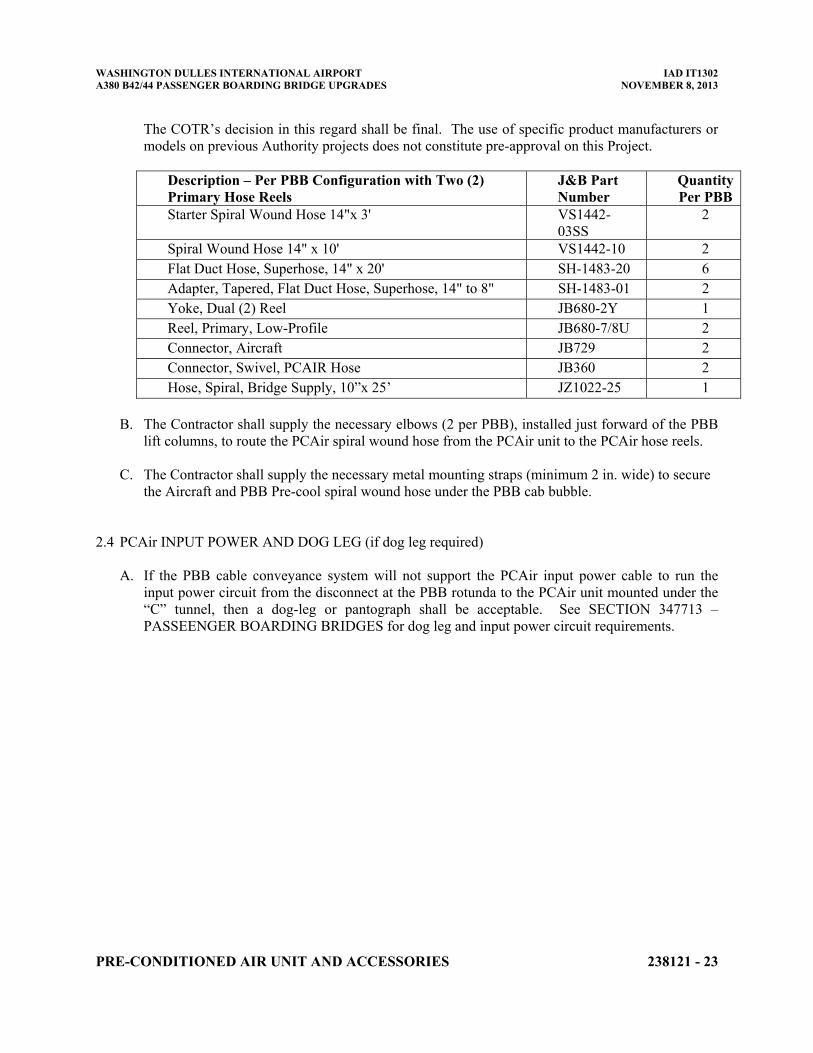
WASHINGTON DULLES INTERNATIONAL AIRPORT IAD IT1302 A380 B42/44 PASSENGER BOARDING BRIDGE UPGRADES NOVEMBER 8, 2013
PRE-CONDITIONED AIR UNIT AND ACCESSORIES 238121 - 23
The COTR’s decision in this regard shall be final. The use of specific product manufacturers or models on previous Authority projects does not constitute pre-approval on this Project.
Description – Per PBB Configuration with Two (2) Primary Hose Reels
J&B Part Number
Quantity Per PBB
Starter Spiral Wound Hose 14"x 3' VS1442-03SS
2
Spiral Wound Hose 14" x 10' VS1442-10 2 Flat Duct Hose, Superhose, 14" x 20' SH-1483-20 6 Adapter, Tapered, Flat Duct Hose, Superhose, 14" to 8" SH-1483-01 2 Yoke, Dual (2) Reel JB680-2Y 1 Reel, Primary, Low-Profile JB680-7/8U 2 Connector, Aircraft JB729 2 Connector, Swivel, PCAIR Hose JB360 2 Hose, Spiral, Bridge Supply, 10”x 25’ JZ1022-25 1
B. The Contractor shall supply the necessary elbows (2 per PBB), installed just forward of the PBB
lift columns, to route the PCAir spiral wound hose from the PCAir unit to the PCAir hose reels. C. The Contractor shall supply the necessary metal mounting straps (minimum 2 in. wide) to secure
the Aircraft and PBB Pre-cool spiral wound hose under the PBB cab bubble.
2.4 PCAir INPUT POWER AND DOG LEG (if dog leg required)
A. If the PBB cable conveyance system will not support the PCAir input power cable to run the input power circuit from the disconnect at the PBB rotunda to the PCAir unit mounted under the “C” tunnel, then a dog-leg or pantograph shall be acceptable. See SECTION 347713 – PASSEENGER BOARDING BRIDGES for dog leg and input power circuit requirements.
WASHINGTON DULLES INTERNATIONAL AIRPORT IAD IT1302 A380 B42/44 PASSENGER BOARDING BRIDGE UPGRADES NOVEMBER 8, 2013
PRE-CONDITIONED AIR UNIT AND ACCESSORIES 238121 - 24
PART 3 - EXECUTION 3.1 FACTORY TESTING
A. Factory testing shall meet the following requirements.
1. The Contractor shall develop a comprehensive Factory Test Plan, identifying the specifics of the
tests to be carried out, and the acceptance criteria of such test, to ensure the PCAir units comply with the requirements of the Specification and Contract Documents.
2. The Factory Test Plan shall be submitted to the COTR 60 days prior to the factory tests being
conducted.
3. At a minimum, the following tests shall be part of the PCAir Factor Test Procedure. a. At specified cooling design day conditions, verify temperature, pressure and volume of unit
on all Cooling Mode settings, including Vent and Pre-cool. b. At specified heating design day conditions, verify temperature, pressure and volume of unit
on all Heat Mode Settings. c. The above 2 tests shall be conducted with the PCAir unit fully contained within an
environmentally controlled test chamber that can create Design Day Conditions (both heating and cooling) so that the unit can be tested and the test results can confirm that the PCAir unit will produce an airflow at the required temperature, volume and pressure at Design Day conditions.
d. Verify all functions of Pendant Control e. Verify noise level, per the requirements of:
(1) ARP 1801 - Measurement of Exterior Sound Level of Specialized Aircraft Ground Support Equipment.
(2) ARP 5374 - Method of Testing Preconditioned Air Equipment.
4. The results of the Factory Testing shall be supplied to the COTR prior to shipment. The Authority will NOT approve shipment of the PCAir units without the COTR’s review and approval of the Factory Test Results.
3.2 PRE-SHIPMENT INSPECTION BY THE AUTHORITY
A. See SECTION 347713 – PASSENGER BOARDING BRIDGES for factory inspection requirements. Three (3) weeks prior to shipment of any PCAir units, notify the COTR of the specific date the factory testing will be conducted.
3.3 INSTALLATION
A. PCAir units shall be mounted underneath the PBB behind the bogie wheels.
1. Vibration isolation shall be provided so that the PCAir units shall not transmit vibration to the passenger bridges.
WASHINGTON DULLES INTERNATIONAL AIRPORT IAD IT1302 A380 B42/44 PASSENGER BOARDING BRIDGE UPGRADES NOVEMBER 8, 2013
PRE-CONDITIONED AIR UNIT AND ACCESSORIES 238121 - 25
2. Connections from the PCAir unit to the PCAir pendant control, PCAir temperature probe, and PBB interlock circuits shall be run through rigid conduit to the entry points of the PBB console or PBB cable scissor.
B. The Contractor shall supply the necessary drawings, instructions, manuals and all materials,
accessories, components, etc., required to fully assemble, commission and test the PCAir units and accessories.
C. All such materials shall be packaged as an Installation “Kit” with clearly labeled and indexed
containers and materials within containers. These Installation Kits shall be packaged and protected so that they may be stored in an exterior uncovered environment for several months.
D. The PCAir manufacturer shall provide qualified manufacturer's technical representative / service
personnel during the entire installation process for the PCAir to assure a proper installation, and to ensure adequate and reliable field service support to correct any and all equipment failures that may occur during the commissioning and testing and during the initial operating period. This representation shall be available to the COTR at no charge for the first 60 days after installation. The manufacturer's field service representative shall monitor and ensure that the approved PBB Installation Subcontractor follows:
1. The manufacturer's field installation manual.
2. Compliance with all safety requirements.
3. Accurate and complete reports and records maintenance
E. Refer to SECTION 347713 – PASSENGER BOARDING BRIDGES for additional installation
information, requirements and specifications
WASHINGTON DULLES INTERNATIONAL AIRPORT IAD IT1302 A380 B42/44 PASSENGER BOARDING BRIDGE UPGRADES NOVEMBER 8, 2013
PRE-CONDITIONED AIR UNIT AND ACCESSORIES 238121 - 26
PART 4 - CONTRACTOR FIELD QUALITY CONTROL REQUIREMENTS 4.1 QUALITY ASSURANCE
A. For additional Quality Control requirements refer to DIVISION 1 SECTION - QUALITY
REQUIREMENTS.
B. The following describes the minimum inspection and testing required in the Contractor's Field Quality Control Program for the work of this section. THE IMPLEMENTATION OF A CONTRACTOR QUALITY CONTROL PROGRAM DOES NOT RELIEVE THE CONTRACTOR FROM THE RESPONSIBILITY TO PROVIDE WORK IN ACCORDANCE WITH THE CONTRACT DOCUMENTS, APPLICABLE CODES, REGULATIONS, AND GOVERNING AUTHORITIES. The Contractor Quality Control Program shall include, but not be limited to, the elements included herein. These elements are provided only as a minimum starting point for the Contractor to use to generate the complete Contractor's Quality Control Program.
4.2 FIELD QUALITY CONTROL
A. Refer to SECTION 347713 – PASSENGER BOARDING BRIDGES for the requirements for
PCAir unit start up and testing.
4.3 TRAINING
A. Training:
1. The Contractor shall conduct training utilizing prepared texts, slides, and other instructional
aids as appropriate.
2. Provide a minimum 4 hours of operator training and 8 hours of maintenance training by a qualified manufacturer's representative for the PCAir’s purchased under this Contract. a. Training shall be conducted at the installation site and in classrooms as designated and
provided by the Authority. b. Maintenance training shall include proper demonstration of cut-away models of critical
parts, full instruction of proper maintenance and trouble shooting, and instructions on proper use of manuals. Operator training shall include proper demonstration as well as actual use of correct PCAir operations to avoid damaging the equipment or aircraft or personal injury, by improper use of the PCAir and its controls.
c. Instruct Authority's personnel in proper use, operation, and daily maintenance of the PCAir. Review emergency provisions, including emergency access and procedures to be followed at time of failure in operation and other building emergencies. Train Authority's personnel in normal procedures to be followed in checking for sources of operational failures or malfunctions. Confer with Authority on requirements for a complete PCAir maintenance program.
d. Instruct Authority’s personnel in the use of the hardware / software tools required to upload and download control programs, trouble shoot the PCAir control software, perform equipment diagnostics and review data flow.
WASHINGTON DULLES INTERNATIONAL AIRPORT IAD IT1302 A380 B42/44 PASSENGER BOARDING BRIDGE UPGRADES NOVEMBER 8, 2013
PRE-CONDITIONED AIR UNIT AND ACCESSORIES 238121 - 27
3. Training dates shall be mutually agreed upon by the Contractor and the COTR and shall be at
dates prior to acceptance by the Authority.
4. The Authority will assign the individuals and/or companies to be trained

WASHINGTON DULLES INTERNATIONAL AIRPORT IAD IT1302 A380 B42/44 PASSENGER BOARDING BRIDGE UPGRADES NOVEMBER 8, 2013
PRE-CONDITIONED AIR UNIT AND ACCESSORIES 238121 - 28
END OF SECTION 238121
WASHINGTON DULLES INTERNATIONAL AIRPORT IAD IT1302 A380 B42/44 PASSENGER BOARDING BRIDGE UPGRADES NOVEMBER 8, 2013
400Hz GROUND POWER UNIT AND ACCESSORIES 263543 - 1
SECTION 263543 400Hz GROUND POWER UNIT AND ACCESSORIES PART 1 - GENERAL 1.1 SUMMARY
A. The Metropolitan Washington Airports Authority (MWAA) is undertaking a project to modify
two (2) gates (B42/B44) at the Dulles International Airport (IAD) to be able to service the British Airways A380, which is planned to begin service at IAD sometime in the 3rd quarter of 2014. MWAA has an operational date requirement for this project of August 1, 2014.
B. As part of this project, MWAA will purchase two (2) Passenger Boarding Bridges (PBB), two (2)
Fixed Walkway sections and two (2) 180Kva Dual Output 400Hz Aircraft Ground Power Units (GPU) and two (2) 90/100 ton Aircraft Preconditioned Air Units (PCAir). The Contractor shall design, manufacture and deliver this equipment to IAD NO LATER THAN July 1, 2014. Liquidated damages shall apply if the July 1, 2014 date is not achieved and the August 1, 2014 operational date is also not achieved.
C. The GPU shall be designed and manufactured as indicated in the Project Specifications, including
all structural, support, mechanical, electrical, and finish requirements to serve the aircraft mix indicated in the Project Specifications. .
D. The Contractor supplying the new GPU shall also be required to fully coordinate with the
Contractor performing the other part of this project, which includes the terminal building modifications, construction of new Walkway and PBB foundations, installation, testing and commissioning of the new equipment and the removal and storage of the existing PBB, PCAir and GPU at Gates B42 / B44.
E. As specified in this SECTION, provide the necessary management, supervision, labor,
materials, supplies and equipment to provide Preconditioned Air Units (PCAir) and accessories.
1. Supply new 180Kva Dual Output 400Hz GPU units on the new Passenger Boarding Bridges
at B42 and B44. 2. Supply new GPU accessories (e.g. cable hoists, output cables, pendant controls, mounting
brackets and hardware, etc.) for Gates B42 and B44.
F. Related Work Specified Elsewhere.
1. DIVISION 01 – GENERAL REQUIREMENTS 2. SECTION 238121 - PRECONDITIONED AIR UNIT AND ACCESSORIES 3. SECTION 347713 - PASSENGER BOARDING BRIDGES
1.2 REFERENCES
A. The latest edition of the publications listed below form a part of this specification to the extent
referenced. The publications are referred to in the text by the basic designation only.
WASHINGTON DULLES INTERNATIONAL AIRPORT IAD IT1302 A380 B42/44 PASSENGER BOARDING BRIDGE UPGRADES NOVEMBER 8, 2013
400Hz GROUND POWER UNIT AND ACCESSORIES 263543 - 2
1. International Electrotechnical Commission (IEC):
a. IEC 158-1 - Rating and Testing for Contactors. 2. Institute of Electrical and Electronics Engineers (IEEE):
a. IEEE C2 - National Electrical Safety Code (ANSI). b. IEEE Std 519 - Harmonic Control in Electrical Power Systems. c. IEEE Std 1100 - Powering and Grounding Electronic Equipment (IEEE Emerald Book). d. IEEE Std 1159 - Monitoring Electric Power Quality. e. IEEE C62.41 - Surge Voltages in Low-Voltage AC Power Circuits (ANSI).
3. U.S. Department of Defense (DOD):
a. MIL-STD-461 - Control of Electromagnetic Interference Characteristics of Subsystems and Equipment.
b. MIL-STD-704 - Aircraft Electric Power Characteristics. c. MIL-PRF-24021K - Electric Power Monitors, External Aircraft.
4. National Electrical Manufacturers Association (NEMA):
a. NEMA 250 - Enclosures for Electrical Equipment (1000 Volts Maximum). b. NEMA ST 20 - Dry-Type Transformers for General Applications.
5. National Fire Protection Association (NFPA):
a. NFPA 70 - National Electrical Code. 6. Underwriters Laboratories (UL):
a. UL 489 - Molded-Case Circuit Breakers, Molded-Case Switches, and Circuit-Breaker Enclosures Ninth Edition.
b. UL 506 - Specialty Transformers Twelfth Edition. c. UL 1012 - Safety Power Units Other Than Class 2 Sixth Edition. d. UL 1449 - Transient Voltage Surge Suppressors Second Edition.
1.3 SUBMITTALS
A. Contractor Submittals and RFI’s shall be transmitted in the form and by the process as indicated
in SECTION 013100 – PROJECT MANAGEMENT AND COORDINATION, SECTION 013200 – DESIGN AND CONSTRUCTION PROGRESS DOCUMENTATION and SECTION 013300 - SUBMITAL
B. Include, but not limited to, the following:
1. Shop Drawings:
a. 180Kva Dual Output 400Hz Ground Power Unit b. Cable Hoists c. Pendant Controls d. Mounting details for Ground Power Unit and Cable Hoists
2. Product Data:
a. Output cables. 3. Test Reports:
a. Performance tests. Provide in accordance with the requirements set forth in paragraph
WASHINGTON DULLES INTERNATIONAL AIRPORT IAD IT1302 A380 B42/44 PASSENGER BOARDING BRIDGE UPGRADES NOVEMBER 8, 2013
400Hz GROUND POWER UNIT AND ACCESSORIES 263543 - 3
entitled "Quality Assurance" Certify tests were conducted on each GPU in accordance with the paragraph entitled “Factory Testing” and "Field Quality Control" and certify GPU satisfactorily operated within specified limits. Report shall include copies of the test procedures and test data and results.
4. Certificates:
a. Qualifications of manufacturer. b. Work plan. c. Routine factory test plan, report, and procedures. d. Special factory test plan, report, and procedures. e. Field test plan, report, and procedures. f. Authorization to Mark for UL.
5. Manufacturer's Field Reports:
a. Routine factory tests report. b. Special factory tests report. c. Burn-in test.
6. Operation and Maintenance Data:
a. Ground Power Unit and Cable Hoist. b. Description and operation of all systems and components. c. Electrical drawings specific for each bridge furnished. Provide two sets of bound,
laminated electrical drawings for each GPU to be placed in the control console. d. Maintenance instructions, including troubleshooting/diagnostic guidelines. e. Overhaul instructions. f. List of parts and part numbers. g. Illustrated parts list of all components. h. Recommended spare parts list and sources. i. Complete and detailed Preventative Maintenance Program for each type of GPU
furnished under this Contract. j. Submit operation and maintenance manuals in accordance with DIVISION 1.
7. Documentation of coordination with the PBB manufacturer indicating coordination efforts,
including mounting requirements, loads, power, communication, control, interlock, precool control, and condensate coordination. COTR shall approve of GPU system connections drawings.
8. In addition to the manufacturer’s complete illustrated parts manual, provide a listing of the
manufacturer’s recommended stocking levels of critical repair parts to include the manufacturer’s item description, part number, assemblies per unit, the recommended on-hand stocking level, and the current list price.
9. Contractor will supply at Substantial Completion, copies of any and all software and the
required interface cables so that the Authorities maintenance personnel can reload the GPU’s control software and make any necessary adjustments to the GPU’s control software. If any software licenses are required to use this software, the Contractor shall supply any and all required licenses
1.4 QUALITY ASSURANCE
WASHINGTON DULLES INTERNATIONAL AIRPORT IAD IT1302 A380 B42/44 PASSENGER BOARDING BRIDGE UPGRADES NOVEMBER 8, 2013
400Hz GROUND POWER UNIT AND ACCESSORIES 263543 - 4
A. Refer to SECTION 014000 – QUALITY REQUIREMENTS for additional information and additional project quality control requirements.
B. Ground Power Unit and Cable Hoist Drawings:
1. Furnish scaled drawings of enclosure outline including front, top, side views, and overall
dimensions. Provide external power and control wiring and cable connections. Provide single line, schematic, and wiring diagrams. Drawings shall include details of input and output circuit breakers, contactors, rectifiers, surge protectors, and control devices. Drawings shall include conduit entry and exit locations.
C. Qualifications of Manufacturer:
1. Submit a certification that the GPU manufacturer has been in the specific business to design
and manufacture the specially constructed GPU required by this Specification. The Contractor must have a minimum of ten (10) years’ experience in producing the GPU design proposed. The GPU design being proposed MUST have been in continuous use for a minimum of ten (10) years. Specific design features included in this ten (10) year requirement shall be the a. technology for converting AC input power to 400Hz aircraft power b. electronic systems and components used in the power conversion technology.
2. Experience in manufacturing motor generator sets does not qualify as equivalent. Experience in manufacturing portable power units on wheels for temporary power does not qualify.
D. Work Plan:
1. Submit a written schedule of dates of routine and special factory tests, installation, field
tests, and operator training for the GPU. Furnish a list of instrumentation equipment for factory and field test reports.
E. Routine Factory Test Plan, Report, and Procedures:
1. Provide detailed description of tests procedures, including test equipment and setups, to be
used to ensure the GPU meets the performance specification and explain the test methods to be used. As a minimum, the tests procedures shall include the tests required under the paragraph entitled "Routine Factory Tests."
F. Special Factory Test Plan, Report and Procedures:
1. Provide detailed description of tests procedures, including test equipment and setups, used to
ensure the GPU meets the performance specification and explain the test methods used. As a minimum, the tests procedures shall include the tests required under the paragraph entitled "Special Factory Tests."
G. Field Test Plan, Report, and Procedures:
1. Provide detailed description and dates and times scheduled for performance of tests, and
detailed description of test procedures, including test equipment and setups, used to ensure the GPU meets the performance specification and explain the test methods to be used. As a minimum, the test procedures shall include the tests required under the paragraph entitled
WASHINGTON DULLES INTERNATIONAL AIRPORT IAD IT1302 A380 B42/44 PASSENGER BOARDING BRIDGE UPGRADES NOVEMBER 8, 2013
400Hz GROUND POWER UNIT AND ACCESSORIES 263543 - 5
"Field Quality Control." Test reports shall include power quality measurement data collected in accordance with IEEE Std 1159.
H. UL Listing:
1. Submit copies of current UL listings for the system, of the actual kVA rating or greater,
with copies of the actual UL test results.
I. Routine Factory Tests Report:
1. Certify tests were conducted on each GPU in accordance with the requirements set forth in paragraph entitled "Routine Factory Tests" and certify GPU satisfactorily operated within specified limits. Report shall include copies of the test procedures and test data and results.
J. Special Factory Tests Report:
1. Certify tests were conducted on a GPU of the same design, construction and kVA and voltage
rating to be provided and in accordance with the requirements set forth in paragraph entitled "Special Factory Test" and certify GPU operated without malfunctioning within specified limits. Report shall include copies of the test procedures, instrumentation, and test data and results.
K. Other Factory and Field Test Requirements
1. Refer to SECTION 347713 – PASSENGER BOARDING BRIDGES for additional factory
and field testing requirements. . 1.5 SEQUENCING AND SCHEDULING
A. The Contractor shall deliver the GPU units and any accessories, as specified herein, NO LATER THAN JULY 1, 2014. Liquidated damages, as called for in the Contract documents shall apply if delivery to IAD is later than July 1, 2014.
B. Working Area: Coordinate location of GPU staging area, storage area and erection area with the
COTR.
C. Coordinate with the contractor performing the installation of the PBB, 400 Hz GPU, PCAir units and bag slides.
D. Electrical power, communication, security and fire alarm services. Coordinate with the
contractor performing the design and installation of this scope of work for this Project. 1.6 WARRANTY
A. Two year warranty on parts and labor. Manufacturer/Contractor agrees to replace, repair, or
restore defective materials and workmanship of GPU work during warranty period of 2 years from final acceptance. In addition, the Manufacturer/Contractor agrees to replace, repair or restore any GPU bus capacitors for a period of five (5) years. This warranty shall be in addition to, and not a limitation of, other rights the Authority may have against the Contractor under the Contract Documents.
WASHINGTON DULLES INTERNATIONAL AIRPORT IAD IT1302 A380 B42/44 PASSENGER BOARDING BRIDGE UPGRADES NOVEMBER 8, 2013
400Hz GROUND POWER UNIT AND ACCESSORIES 263543 - 6
B. "Defective" is defined to include, but not by way of limitation, operation or control system failures, performances below required minimums, excessive wear, unusual deterioration or aging of materials or finishes, unsafe conditions, the need for excessive maintenance, abnormal noise or vibration and similar unusual, unexpected and unsatisfactory conditions.
C. Warranty Claim Response Time: The manufacturer shall ship repair parts and send a qualified
service technician (if requested), to the Authority within 24 hours of being notified of an equipment failure while under warranty and parts shall be deliver at the applicable Authority facility within 48 hours from the time the order was placed by the Authority. If the manufacturer is unable to obtain the parts to restore the equipment to service, the Authority reserves the right to obtain the replacement parts or service elsewhere and charge the total cost to the manufacturer, including labor and administrative fees.
D. In the event of a significant, complex, or catastrophic failure of an integrated component of the
GPU and at the Airports Authority’s request, the manufacturer will provide freight and logistics to ship a failed ground power unit back to the manufacturer for factory testing and repairs while the unit is still under warranty and to return the repaired and tested component back to the Airports Authority for installation. Alternately, the GPU manufacture can opt to provide a qualified technician at IAD to trouble shoot and repair such significant, complex or catastrophic failure
1.7 MAINTENANCE
A. Additions to Operation and Maintenance Manuals: Include the following in the actual
GPU provided.
1. A "one-line diagram" from service entrance to 400 Hz utilization panel or point. 2. A weatherproof, tear resistant plastic data sheet with operating instructions for each unit
including startup and shutdown procedures.
B. Extra Materials:
1. Software and any required licenses per 1.3.9
WASHINGTON DULLES INTERNATIONAL AIRPORT IAD IT1302 A380 B42/44 PASSENGER BOARDING BRIDGE UPGRADES NOVEMBER 8, 2013
400Hz GROUND POWER UNIT AND ACCESSORIES 263543 - 7
PART 2 - PRODUCTS 2.1 GENERAL
A. Unless indicated otherwise, all Equipment and Material shall be new, undamaged and meet the
requirements of Underwriter's Laboratories, Inc. (UL). Where UL requirements are not applicable, equipment and material shall be identified as such by Contractor and approved by Authority before purchase and installation.
B. In this Specification, the term “or Authority approved equal” may be used to indicate that the
Contractor shall have the option of proposing an alternative to what has been specified. The Contractor’s alternative must be equal to or exceed the performance, functionality and safety requirements of the Specification.
2.2 MANUFACTURERS
A. Subject to Compliance with requirements, the Contractor shall make every effort to supply
materials that match the existing equipment in use at IAD so as to minimize the spare parts requirements for the Authority’s Maintenance group. In addition, the Authority has established a minimum standard of quality and reliability for certain parts and components that are routinely purchased to maintain the Authority’s equipment. The list below has been presented to reflect this standard and in support of the Authority’s spare parts objectives. The manufacturers on this list shall not be perceived or construed as favored or preferred. This list shall, in no way, preclude other manufacturers, provided that their equipment and components have been reviewed by the COTR and determined to be of equivalent or similar quality, functionality, and reliability. The COTR’s decision in this regard shall be final. The use of specific product manufacturers or models on previous Authority projects does not constitute pre-approval on this Project. 1. Ground Power Units:
a. JBT Aero Tech. b. ITW Hobart c. FCX
2. GPU Output Cables
a. J&B Aviation 2.3 DESIGN AIRCRAFT:
A. Narrow Body (NB): A321-200 B. Wide Body (WB): B787-800 C. Jumbo (J): A340-300, A340-600, B777-200LR, B777-300ER, B747-400, A-380-800
2.4 400Hz GROUND POWER UNIT
A. Input Power
WASHINGTON DULLES INTERNATIONAL AIRPORT IAD IT1302 A380 B42/44 PASSENGER BOARDING BRIDGE UPGRADES NOVEMBER 8, 2013
400Hz GROUND POWER UNIT AND ACCESSORIES 263543 - 8
1. Input Voltage: The GPU shall operate with input voltages not varying more than plus 10% or minus 15% of nominal voltage rating.
2. Input Frequency: The GPU shall operate on 50/60 Hz input power frequencies. 3. Input Current Requirements at Rated Load: The nominal input current at rated load shall be
480 Vac and a maximum of 150 amps. 4. Input Inrush Current: On start up the GPU shall withstand inrush current of up to 100% of
that input current required when the GPU is operating at rated load output. 5. Input Power Factor: The GPU shall operate with an input power factor to .95 or greater at
loads of 25% to 100% of the nominal rated load for the unit. 6. Input Phase Rotation: The GPU shall be input phase rotation independent, allowing the GPU
to be connected to the incoming power without regard for phase rotation. 7. Input Harmonic Distortion: shall be a maximum of 10%. 8. Efficiency: The overall efficiency of the GPU shall not be less than 91% at 50% or greater
load. 9. Input Power Break: The GPU shall be capable of supplying uninterrupted power to the
aircraft during a micro break on the input power. 10. Input Circuit Breaker: The GPU will contain an internally mounted circuit breaker on the
input power line(s) to allow the input power to be removed in the case of a fault or for maintenance.
11. Input Power Disconnect: A separate GPU circuit breaker shall be incorporated into the PBB
disconnect cabinet or shall be in a separate GPU disconnect mounted at the PBB rotunda. Power shall be supplied from this disconnect to the GPU via separate cabling integrated with the PBB cable conveyance system.
12. Unit Disconnect Breaker: The GPU shall be equipped with either a) a fixed mounted shunt
trip breaker or b) a switch; that shuts off power to the output cables, shuts down the SCR’s and discharges lethal power from the DC Bus, going from 650 vdc to 50 vdc in 1 to 2 seconds and shall be totally discharged in 15 to 20 seconds. This breaker or switch shall also serve as a door or panel interlock which will activate when the main panel door is opened. A bypass door interlock switch shall be provided to allow testing and repair of the unit with the doors opened.
B. Output Power – 400Hz AC 1. Output Voltage: Shall be adjustable by plus or minus 10% of 115 Volts. 2. Output Voltage Drift: The output voltage shall not change by more than 1% of its originally
set value with the unit operating at a constant load, a change in ambient temperature up to 55 degrees C in an eight hour period or as the unit stabilized from a cold condition at any load.
3. Output Voltage Regulation: Voltage regulation shall not exceed ± 1% from no load to full
WASHINGTON DULLES INTERNATIONAL AIRPORT IAD IT1302 A380 B42/44 PASSENGER BOARDING BRIDGE UPGRADES NOVEMBER 8, 2013
400Hz GROUND POWER UNIT AND ACCESSORIES 263543 - 9
load and from rated load to no load with ± 10% input voltage. Output voltage shall recover to the steady state condition less than 50 ms after any load change up to 100%. The voltage shall not exceed the limits of MIL-STD-704E during transient recovery.
4. Output Voltage Distortion (Total Harmonic Distortion): Total harmonic distortion on the
output voltage waveform shall not exceed 3% (line to line/line to neutral) with any rated load up to 100% load. Any single harmonic will not exceed 2%.
5. Output Voltage DC Content: The DC voltage at the output terminals will not exceed 0.1
volts under any rated load conditions. 6. Output Voltage Modulation: The modulation of the voltage waveform shall not exceed 0.5%
as measured from the peak of one waveform to the peak of another adjacent waveform under steady state, rated load conditions.
7. Output Voltage Balance: The maximum output voltage deviation of any of the three output
phases will not exceed 1% from the average of the three output phase voltages under balanced load conditions. Voltage unbalance shall not exceed 3 volts, with 10% unbalanced load on 1 phase and shall meet MIL-STD-704E, figure 1 and ARP1940, 3.1.5.10.
8. Output Frequency Regulation: Shall be 400 Hz plus or minus 0.1% at any rated load
condition. 9. Output Frequency Modulation: Shall be less than ± 0.25% of the period of output voltage
wave. 10. Output Phase Displacement: The phase angle between each of the three output phases will be
120 degrees plus or minus 1.5 degrees under all rated, balanced load conditions. The phase angle displacement with an unbalanced load of 15% the unit’s rated current shall be 120 degrees plus or minus 4 degrees.
11. Output Current: 90Kva (260 amps) at .8 power factor load continuous. 12. Bus Capacitors: Bus capacitors shall be the polypropylene type and not electrolytic
capacitors. 13. No Break Power Transfer: The GPU must be capable of continuous operation during a
switch from the Aircraft APU to the GPU. 14. Line Drop Compensation: The GPU shall have a built-in automatic line drop compensation,
which shall be adjustable from 1% to 8% of rated voltage at rated load. 15. Power Factor: The GPU will be capable of operating with an output power factor of 0.0 to
1.0.
C. Overload 1. Overload Capacity: The GPU shall be capable of supplying overloads of up to 125% for 10
minutes, 150% for 30 seconds and 200% for 10 seconds. 2. Short Circuit Capability: The GPU shall withstand an output short and the short shall be
WASHINGTON DULLES INTERNATIONAL AIRPORT IAD IT1302 A380 B42/44 PASSENGER BOARDING BRIDGE UPGRADES NOVEMBER 8, 2013
400Hz GROUND POWER UNIT AND ACCESSORIES 263543 - 10
cleared by internal solid-state circuitry.
D. Fault Systems 1. The GPU will be capable of monitoring the following items and shutting down in the event
they are out of tolerance. The faults listed below will be displayed. a. Input voltage 10% higher than nominal rating b. Input voltage 15% less than nominal rating c. Output voltage less than 100 Vac per MIL-STD-704E d. Output voltage greater than 125 Vac per MIL-STD-704E e. Output overload f. No 28vdc returned on EF wires g. EF wire voltage greater than 60v h. DC bus faults i. Over temperature of heat sink j. Output frequency fault
2. The GPU shall be capable of performing a “self-check” of the output power quality before
allowing power to be supplied to the aircraft.
E. Indicators 1. The GPU shall display the following information using an LCD or LED or via downloading
to the Authority’s laptop PC via an RS232 port. If the use of an RS232 port interface is required, the Contractor shall supply the necessary cables and software to connect to the Authority’s laptop to the GPU, retrieve and display the required data. a) Input voltage – each phase and average b) Input current – 3 phase average c) Output voltage – each phase and average d) Output current – each phase and average e) Output Kva (total) or Vdc (total) f) Output frequency g) Event History. h) Unit Settings
2. Front panel lights will indicate the following:
a) Fault occurred b) Input voltage applied to unit c) 28Vdc bypass switch in bypass position d) Output voltage present, unit is connected to aircraft and operating e) 28Vdc EF voltage missing
F. Switches And Controls
1. The GPU and Cable Hoist shall be controlled by a single Pendant Control mounted near the
wheel bogie of the PBB. a. The Pendant Control shall NOT be mounted on any part of the PBB that elevates or in a
location that which would pose a safety hazard to ramp personnel using the pendant control.
b. Pendant control for the GPU / Cable Hoist shall be mounted on a plate attached to the wheel bogie cross tube and the plate shall be painted per the same process and exterior
WASHINGTON DULLES INTERNATIONAL AIRPORT IAD IT1302 A380 B42/44 PASSENGER BOARDING BRIDGE UPGRADES NOVEMBER 8, 2013
400Hz GROUND POWER UNIT AND ACCESSORIES 263543 - 11
color as the PBB. 2. All voltages in the Pendant Control shall be low voltage – 28 volts maximum. 3. The Pendant Control shall comply with the following.
a. All wiring shall be identified using stamped wire or other Authority approved wire labels. If stamped wires are used, number must be visible at termination point. Wires are to be numbered in a logical sequence and all wire numbers are to be indicated on electrical schematics.
b. Spare wires shall be numbered and also labeled as "SPARE". Spare wires shall be indicated on the electrical schematics.
c. All wires, including spares, within Pendant Control shall be neatly secured and routed. Wire routing trays shall be used when interior space permits.
d. All wiring shall be brought to terminal blocks. The wiring shall be formed and restrained to give a neat appearance. Wire splices of any type shall NOT be used. Terminals must meet the applicable requirements of SAE J561, J858 and J928. Wires must meet the bend radius requirements of NEC. Ninety degree bends shall not be allowed.
e. Terminal blocks shall be of finger proof or tamper proof design or shall have a protective cover supplied by the terminal block manufacturer.
f. Grommets and suitable anti-chafe material shall be used where wires are required to pass through structure or similar relief or opening which exposes the wire to possible chafing.
g. Quick Disconnect fittings must be MS standard receptacles and plugs and shall be UL or ETL approved. Quick Disconnect receptacles and plugs shall be labeled with a permanent type label to indicate which receptacle goes with which plug.
h. Wire ties SHALL NOT be used to securing any wiring. NEC / UL approved clamps and methods must be used to secure wiring.
4. Pendant control enclosures shall be SST and NEMA rated weatherproof. Cover plate shall
have self-retaining screws. Pendant Control enclosure shall have a means to allow water to drain from the bottom of the enclosure
5. The Pendant Control shall have the following buttons and indicators for the 400Hz GPU
functions. The push buttons and indicators shall be oriented from top to bottom in the pendant control in the order listed below. a. Up push button – for retracting the Cable Hoist b. Down push button - for extending the Cable Hoist c. Green LED indicating light, with clear lens, which indicates the unit is connected to
aircraft and operating. d. Start push button – for starting the unit e. Stop push button – for stopping / resetting the unit.
6. Each button on the Pendant control or indicator shall be labeled with an engraved placard
identifying the button or indicator function. 7. .In addition to the Pendant Control, the following controls and indicators shall be located on
the outside of the GPU unit: a. Start / Stop / Reset push buttons for 400Hz output. b. 400Hz operate light – green LED lamp with clear lens c. 28Vdc Bypass switch and flashing indicator light. d. Red Fault Light e. Error message displays
WASHINGTON DULLES INTERNATIONAL AIRPORT IAD IT1302 A380 B42/44 PASSENGER BOARDING BRIDGE UPGRADES NOVEMBER 8, 2013
400Hz GROUND POWER UNIT AND ACCESSORIES 263543 - 12
f. LCD contrast, if LCD screen is supplied 8. In addition to the Pendant Control, the following controls and indicators shall be located on
the inside of the GPU unit: a. Line drop compensation adjustment b. Voltage adjustment ( ± 10%) c. Hour meter (99,999 hours)
G. External Interface
1. The GPU shall contain either a) externally pluggable connectors or b) internally mounted
terminal blocks for the GPU Pendant Control and PBB Interlock. 2. Internally mounted terminal blocks shall be used for connecting the GPU output cable and
any control functions from the GPU output cable, pendant control or PBB interlock. All connection points shall be clearly labeled as to the function that will connect to them from the GPU output cable, pendant control and PBB interlock. The terminal blocks for the GPU output cables shall be “stud” type.
3. The GPU shall be mounted under the PBB Cab Bubble or PBB C-Tunnel as close to the PBB
Cab Bubble as possible. 4. The GPU shall have yellow and black safety tape applied to the bottom circumference of the
GPU.
H. Physical Characteristics 1. Weight: The GPU shall weigh no more than 2,000 pounds 2. Cabinet Dimensions: The GPU shall be mountable either under the Cab of the PBB or on the
side of the PBB 3. Cabinet Material: The cabinet will be constructed from painted anodized aluminum. Color
will be Manufacturer’s standard color. 4. Weather Rating: The GPU’s cabinet / enclosure shall be rated as NEMA 3R or IEC IP54. 5. Wiring: All internal and external wires or cables shall be numbered or labeled. 6. Connectors: All connectors shall be unique to the point of connections on the boards 7. Terminal Blocks: All wire splicing and connections shall be accomplished on terminal
blocks. Wire splicing, twist connectors, etc. shall not be permitted. 8. Acoustical Noise: The GPU shall not emit more than 70 dBA at 1.5 meter height and 1.0
meter distant. 9. Temperature Rating: The GPU shall be capable of operating temperature of -40 to +55C.
I. OUTPUT CABLES
WASHINGTON DULLES INTERNATIONAL AIRPORT IAD IT1302 A380 B42/44 PASSENGER BOARDING BRIDGE UPGRADES NOVEMBER 8, 2013
400Hz GROUND POWER UNIT AND ACCESSORIES 263543 - 13
1. Contractor shall provide one (1) 400Hz output cable, with connectors, of sufficient length to service the required Aircraft mix. The Contractor shall be responsible to determine mounting location of the GPU on the PBB and the length of the GPU Output Cables in order to service the required aircraft mix.
2. GPU output cable shall be supported at the entrance to the GPU by wire type strain reliefs 3. 90KVa 400Hz output cable shall be solid. 4. The 400Hz cable head nose end shall be “detachable” for ease of maintenance and
replacement and shall be equipped with thermal overload protection. 5. The 400Hz cable head shall have replaceable buttons for 400Hz function of the GPU On / Off
and Cable Hoist Up / Down. 6. The 400Hz output cable wires shall be labeled on the unit connection end with the phase and
function of the wire.
J. Other Design Requirements 1. The GPU shall be sectional in design. Transformer section shall be isolated and separate
from the front and back sections of the unit. 2. Vertical cooling towers or heat sink shall be utilized to cool sensitive internal electronic
components. 3. Cooling Fans shall cool the cooling tower or heat sinks. Any fans that circulate air into the
interior of the GPU must utilize input air that is filtered. The filters shall be easily accessible and removable for cleaning. The filters shall be a washable mesh type.
4. Interior of the unit shall be sealed so that contaminates brought into the unit by cooling fans
will not enter the control sections of the unit. 5. The GPU shall be designed so that the all maintenance, including removal and installation of
all components can be accomplished without removing the GPU from the Passenger Boarding Bridge.
6. GPU shall be interlocked with the PBB to prevent horizontal movement of the PBB if the
GPU unit is powered on. 7. Control Boards.
a. All control boards must be mounted in a card rack OR a board specific location. b. All connection to the boards shall be accomplished by plug in connectors c. Each connector set must be labeled, along with all of its wire connections, to eliminate
misconnections. 8. Wiring and Terminal Blocks
a. Wires shall not be pulled tight in the GPU unit or subjected to chafing or damage by vibration of the GPU or by the operation of the PBB. Wires shall not droop or sag in their routing.
b. All wiring shall be brought to terminal blocks.
WASHINGTON DULLES INTERNATIONAL AIRPORT IAD IT1302 A380 B42/44 PASSENGER BOARDING BRIDGE UPGRADES NOVEMBER 8, 2013
400Hz GROUND POWER UNIT AND ACCESSORIES 263543 - 14
c. Wire splices of any type shall NOT be used. d. Wiring shall be formed and restrained to give a neat appearance. e. All wires, including spares, within junction boxes, control cabinets, disconnects, other
electrical enclosures shall be neatly secured and routed. Wire routing trays shall be used when interior space permits.
f. All wiring shall be identified using stamped labels or other Authority approved wire labels. i) Labels shall be visible and located within 1 in. of their termination point. ii) Wires are to be numbered in a logical sequence and all wire numbers are to be
indicated on electrical schematics. g. Spare wires shall be numbered and also labeled as “SPARE”. Spare wires shall be
indicated on the electrical schematics. h. Wires must meet the bend radius requirements of NEC. Ninety degree bends shall not be
allowed. i. Ferrules or insulated ring terminals shall be used on any fine stranded wire, depending on
the terminal block connection. ii) Fork or Spade terminals shall NOT be allowed. iii) Direct connection of fine stranded wire to a terminal block shall NOT be allowed.
j. Terminal blocks shall be either: iv) Finger proof or tamper proof design v) Stud or open style design with a protective cover supplied by the terminal block
manufacturer. vi) Authority approved equal
i. Other terminal block designs shall not be accepted. j. Terminal blocks must meet the applicable requirements of SAE J561, J858 and J928. k. NEC / UL approved clamps and or other Authority approved methods must be used to
secure wiring. 9. Grommets and suitable anti-chafe material shall be used where wires are required to pass
through structure or similar relief or opening which exposes the wire to possible chafing. 10. The front and rear door of GPU shall be hinged to allow for maintenance and equipped with a
door interlock switch that trips the unit’s main shunt trip breaker when opened. The door interlock must be able to be by-passed for maintenance access to the unit.
11. The front and rear door of GPU shall be lockable to prevent unauthorized access into the unit.
There shall be two lockable latches on each door, on either side of the door. 12. The GPU shall be able to provide the required signal to the PBB and provide a suitable
connection for the interlock wiring. 13. Attached to the interior of the GPU’s front door shall be a:
a. laminated drawing which provides an elevation view of the front internal compartment of the GPU and identifies each component’s location, as well as the component description and manufacture’s part number.
b. wiring schematic showing the all wires by wire number and termination point for connections visible from the front of the unit.
14. Attached to the interior of the GPU’s rear door shall be a:
a. laminated drawing which provides an elevation view of the rear internal compartment of the GPU and identifies each component’s location, as well as the component description
WASHINGTON DULLES INTERNATIONAL AIRPORT IAD IT1302 A380 B42/44 PASSENGER BOARDING BRIDGE UPGRADES NOVEMBER 8, 2013
400Hz GROUND POWER UNIT AND ACCESSORIES 263543 - 15
and manufacture’s part number. b. wiring schematic showing the all wires by wire number and termination point for
connections visible from the rear of the unit. 15. If the GPU’s front and / or rear doors are equipped with electrical controls or components, the
doors shall be equipped with grounding straps. a. Grounding straps used on the GPU shall be braided. Wire type straps shall not be
allowed. 16. The GPU shall be equipped with a desiccant filter or other means of removing moisture from
the sections of the GPU containing the circuit boards. 17. An unused holes or penetrations in the exterior of the GPU shall be plugged. If the holes are
threaded, SST bolts shall be used to plug the hole. 18. The GPU shall have an exterior paint system that provides superior corrosion protection.
Exterior casing surfaces, doors, panels shall be primed and have a baked enamel finish coat. Color shall match the color selected by the Authority for the PBB and PCAir.
19. Mounting brackets used to attach the GPU to the PBB shall be painted per the exterior paint
process specified in SECTION 347713 – PASSENGER BOARDING BRIDGES. The color shall match the PBB color.
20. Certifications 1. The GPU shall be certified by a NRTL for compliance to UL-1012 and CSA-C22.2 No.
107.1-01. Evidence of such certification must be supplied with the Contractor’s Proposal. 2. The GPU shall also have an NRTL certification name plate affixed to the GPU.
2.5 CABLE HOISTS
A. Mechanical Design
1. Contractor shall supply one (1) PBB C Tunnel mounted cable hoist and one (1) PBB Cab mounted Cable hoist for the 400hz output cables.
2. Cable hoists shall be interlocked with the PBB to prevent horizontal movement of the PBB if
the Cables Hoist is lowered. 3. The cable hoists shall be mounted on the left side of the PBB. . 4. Three (3) “banana” clips shall be supplied with each cable hoist to stow the GPU output
cable. 5. Cable hoist and mounting brackets shall be painted with the same exterior paint process and
color as the PBB. 6. Cable hoist shall have a bottom cover that prevents birds from gaining access to the interior
of the hoist box.
WASHINGTON DULLES INTERNATIONAL AIRPORT IAD IT1302 A380 B42/44 PASSENGER BOARDING BRIDGE UPGRADES NOVEMBER 8, 2013
400Hz GROUND POWER UNIT AND ACCESSORIES 263543 - 16
7. Cable hoist shall be equipped with anti-rewind switch
B. Electrical Design
1. All control voltages in the cable hoist shall be low voltage - 28 volts maximum.
2. Wiring and Terminal Blocks a. All wiring shall be brought to terminal blocks. b. Wire splices of any type shall NOT be used. c. Wiring shall be formed and restrained to give a neat appearance. d. All wires, including spares, within junction boxes, control cabinets, disconnects, other
electrical enclosures shall be neatly secured and routed. Wire routing trays shall be used when interior space permits.
e. All wiring shall be identified using stamped labels or other Authority approved wire labels. i) Labels shall be visible and located within 1 in. of their termination point. ii) Wires are to be numbered in a logical sequence and all wire numbers are to be
indicated on electrical schematics. f. Spare wires shall be numbered and also labeled as “SPARE”. Spare wires shall be
indicated on the electrical schematics. g. Wires must meet the bend radius requirements of NEC. Ninety degree bends shall not be
allowed. h. Ferrules or insulated ring terminals shall be used on any fine stranded wire, depending on
the terminal block connection. i) Fork or Spade terminals shall NOT be allowed. ii) Direct connection of fine stranded wire to a terminal block shall NOT be allowed.
i. Terminal blocks shall be either: i) Finger proof or tamper proof design ii) Stud or open style design with a protective cover supplied by the terminal block
manufacturer. j. Other terminal block designs shall not be accepted. k. Terminal blocks must meet the applicable requirements of SAE J561, J858 and J928. l. Wire ties SHALL NOT be used to securing any wiring. NEC / UL approved clamps and
methods must be used to secure wiring.
3. Grommets and suitable anti-chafe material shall be used where wires are required to pass through structure or similar relief or opening which exposes the wire to possible chafing.
4. Quick Disconnect fittings must be MS standard receptacles and plugs and shall be UL or ETL approved. Quick Disconnect receptacles and plugs shall be labeled with a permanent type label to indicate which receptacle goes with which plug.
5. The Cable Hoist shall be UL listed or otherwise certified by the 3rd party Nationally Recognized Testing Laboratory (NRTL), such as ETL, for compliance to the applicable UL codes. A name plate with the UL listing or other listing shall be affixed to the unit.
WASHINGTON DULLES INTERNATIONAL AIRPORT IAD IT1302 A380 B42/44 PASSENGER BOARDING BRIDGE UPGRADES NOVEMBER 8, 2013
400Hz GROUND POWER UNIT AND ACCESSORIES 263543 - 17
PART 3 - EXECUTION 3.1 FACTORY TESTING
A. Factory testing shall meet the following requirements.
1. The Contractor shall develop a comprehensive Factory Test Plan, identifying the specifics of
the tests to be carried out, and the acceptance criteria of such test, to ensure the PCAir units comply with the requirements of the Specification and Contract Documents.
2. The Factory Test Plan shall be submitted to the COTR 60 days prior to the factory tests being
conducted.
3. Routine Factory Tests: Test every GPU to assure compliance with the specifications as follows:
a. Load Bank Test: Test for one hour at 50% kW and one hour at approximately 100% kW capacity. Monitor voltage, frequency, and current at 15-minute intervals during testing. b. Efficiency Test: Test efficiency for 25, 50, 75, 90 and 100% loading. c. Burn-in test: Before delivery, operate each GPU for a minimum of 16 hours.
4. Special Factory Test: Test one 180 kVA GPU to assure compliance with the specifications as
follows: a. Harmonic Distortion: Provide test results of input harmonic currents and voltages. The
test data shall include total harmonic distortion and amplitudes of individual harmonics in graphic representation for no load, 25, 50, 75, and 100% load factors.
b. No Load Losses: Operate at no load and nominal input voltage. Measure and record input voltage, output voltage, and output frequency.
c. Voltage balance (output). d. Voltage balance (input). e. Transient voltage dip and response at 0.8 pf (output). f. Frequency regulation (output). g. Overload. h. Each safety operating device. i. Line drop compensation circuit. j. Input current harmonics.
5. The results of the Factory Testing shall be supplied to the COTR prior to shipment. The
Authority will NOT approve shipment of the PCAir units without the COTR’s review and approval of the Factory Test Results.
3.2 PRE-SHIPMENT INSPECTION BY THE AUTHORITY
A. See SECTION 347713 – PASSENGER BOARDING BRIDGES for factory inspection requirements. Three (3) weeks prior to shipment of any GPU units, notify the COTR of the specific date the factory testing will be conducted.
3.3 INSTALLATION
WASHINGTON DULLES INTERNATIONAL AIRPORT IAD IT1302 A380 B42/44 PASSENGER BOARDING BRIDGE UPGRADES NOVEMBER 8, 2013
400Hz GROUND POWER UNIT AND ACCESSORIES 263543 - 18
A. GPU shall be mounted underneath the PBB Cab Bubble.
1. Vibration isolation shall be provided so that the PCAir units shall not transmit vibration to the passenger bridges.
2. Connections from the GPU to the GPU pendant control and PBB interlock circuits shall be
run through rigid conduit to the entry points of the PBB console or PBB cable scissor.
B. The Contractor shall supply the necessary drawings, instructions, manuals and all materials, accessories, components, etc., required to fully assemble, commission and test the PCAir units and accessories.
C. All such materials shall be packaged as an Installation “Kit” with clearly labeled and indexed
containers and materials within containers. These Installation Kits shall be packaged and protected so that they may be stored in an exterior uncovered environment for several months.
D. The GPU manufacturer shall provide qualified manufacturer's technical representative / service
personnel during the entire installation process for the GPU to assure a proper installation, and to ensure adequate and reliable field service support to correct any and all equipment failures that may occur during the commissioning and testing and during the initial operating period. This representation shall be available to the COTR at no charge for the first 60 days after installation. The manufacturer's field service representative shall monitor and ensure that the approved PBB Installation Subcontractor follows:
1. The manufacturer's field installation manual.
2. Compliance with all safety requirements.
3. Accurate and complete reports and records maintenance
E. Refer to SECTION 347713 – PASSENGER BOARDING BRIDGES for additional installation
information, requirements and specifications
WASHINGTON DULLES INTERNATIONAL AIRPORT IAD IT1302 A380 B42/44 PASSENGER BOARDING BRIDGE UPGRADES NOVEMBER 8, 2013
400Hz GROUND POWER UNIT AND ACCESSORIES 263543 - 19
PART 4 - CONTRACTOR FIELD QUALITY CONTROL REQUIREMENTS 4.1 QUALITY ASSURANCE
A. For additional Quality Control requirements refer to DIVISION 1 SECTION - QUALITY
REQUIREMENTS.
B. The following describes the minimum inspection and testing required in the Contractor's quality Control Program for the work of this section. THE IMPLEMENTATION OF A CONTRACTOR QUALITY CONTROL PROGRAM DOES NOT RELIEVE THE CONTRACTOR FROM THE RESONSIBILITY TO PROVIDE WORK IN ACCORDANCE WITH THE CONTRACT DOCUMENTS, APPLICABLE CODES, REGULATIONS, AND GOVERNING AUTHORITIES. The Contractor Quality Control Program shall include, but not be limited to, the elements included herein. These elements are provided only as a minimum starting point for the Contractor to use to generate the complete Contractor's Quality Control Program.
4.2 FIELD QUALITY CONTROL
A. Refer to SECTION 347713 – PASSENGER BOARDING BRIDGES for the requirements for PCAir unit start up and testing.
4.3 TRAINING
A. Training:
1. The Contractor shall conduct training utilizing prepared texts, slides, and other instructional aids as appropriate.
2. Provide a minimum 2 hours of operator training and 4 hours of maintenance training by a qualified manufacturer's representative for the GPU’s purchased under this Contract. a. Training shall be conducted at the installation site and in classrooms as designated and
provided by the Authority. b. Maintenance training shall include proper demonstration of cut-away models of critical
parts, full instruction of proper maintenance and trouble shooting, and instructions on proper use of manuals. Operator training shall include proper demonstration as well as actual use of correct GPU operations to avoid damaging the equipment or aircraft or personal injury, by improper use of the GPU and Cable hoist and their controls.
c. Instruct Authority's personnel in proper use, operation, and daily maintenance of the GPU. Review emergency provisions, including emergency access and procedures to be followed at time of failure in operation and other building emergencies. Train Authority's personnel in normal procedures to be followed in checking for sources of operational failures or malfunctions. Confer with Authority on requirements for a complete GPU maintenance program.
d. Instruct Authority’s personnel in the use of the hardware / software tools required to upload and download control programs, trouble shoot the GPU control software, perform equipment diagnostics and review data flow.
3. Training dates shall be mutually agreed upon by the Contractor and the COTR and shall be at
WASHINGTON DULLES INTERNATIONAL AIRPORT IAD IT1302 A380 B42/44 PASSENGER BOARDING BRIDGE UPGRADES NOVEMBER 8, 2013
400Hz GROUND POWER UNIT AND ACCESSORIES 263543 - 20
dates prior to acceptance by the Authority.
4. The Authority will assign the individuals and/or companies to be trained
END OF SECTION 263543
WASHINGTON DULLES INTERNATIONAL AIRPORT IAD IT1302 A380 B42/44 PASSENGER BOARDING BRIDGE UPGRADES NOVEMBER 8, 2013
PASSENGER BOARDING BRIDGES 347713 - 1
SECTION 347713 PASSENGER BOARDING BRIDGES PART 1 - GENERAL 1.1 SUMMARY
A. The Metropolitan Washington Airports Authority (MWAA) is undertaking a project to modify two (2) gates (B42/B44) at the Dulles International Airport (IAD) to be able to service the British Airways A380, which is planned to begin service at IAD sometime in the 3rd quarter of 2014. MWAA has an operational date requirement for this project of August 1, 2014.
B. As part of this project, MWAA will purchase two (2) Passenger Boarding Bridges (PBB), two (2)
Fixed Walkway sections and two (2) 180Kva Dual Output 400Hz Aircraft Ground Power Units (GPU) and two (2) 90/100 ton Aircraft Preconditioned Air Units (PCAir). The Contractor shall design, manufacture and deliver this equipment to IAD NO LATER THAN July 1, 2014. Liq-uidated damages shall apply if the July 1, 2014 date is not achieved and the August 1, 2014 op-erational date is also not achieved.
C. Regardless if the Authority chooses to purchase the Add Alternate PCAir and GPU, the PBB’s
shall be designed, manufactured and install AS IF, the PCAir and GPU were being purchased. All mechanical, electrical, control, mounting and other requirements needed to support the speci-fied PCAir and GPU SHALL be included with the PBB.
D. The new PBB’s shall match MWAA’s current standard model PBB, which is a three-tunnel,
model A3-68/141 (or equivalent). The fixed walkway sections shall be the same construction as the PBB.
E. The new walkway and PBB foundations for this project are being designed and constructed based
on the foundation loading reactions of the current model Thyssen-Kupp Airport Systems PBB and the Jetway Systems corrugated PBB. PBB designs that would exceed these load reactions shall not be acceptable.
F. The PBB, Walkway, PCAir and GPU shall be designed and manufactured as indicated on the
Drawings and in the Project Specifications, including all structural, support, mechanical, electri-cal, and finish requirements to serve the aircraft mix indicated on drawing IT1302CV03-0002 in APPENDIX I.
G. The Contractor supplying the new PBB, Walkway, PCAir and GPU shall also be required to fully
coordinate with the Contractor performing the other part of this project, which includes the termi-nal building modifications, construction of new Walkway and PBB foundations, installation, test-ing and commissioning of the new equipment and the removal and storage of the existing PBB, PCAir and GPU at Gates B42 / B44.
H. This Section Includes:
1. Passenger Boarding Bridges: Provide two (2) new three-tunnel A3-68/141 (or equivalent)
PBB’s at Gates B42 and B44 at IAD. Two (2) tunnel PBB’s shall not be acceptable. The PBB at B44 shall be a “high lift” PBB to service the U1 door of the A380-800.
2. Walkways: Supply two (2) fixed walkway sections, with the same construction and finishes
WASHINGTON DULLES INTERNATIONAL AIRPORT IAD IT1302 A380 B42/44 PASSENGER BOARDING BRIDGE UPGRADES NOVEMBER 8, 2013
PASSENGER BOARDING BRIDGES 347713 - 2
as the PBB. The walkway at B44 shall be approximately 40 ft. long and shall be sloping up from the terminal building. The walkway at B42 shall be level and shall be approximately 24 ft. long. Specific length and slope shall be as indicated on drawing IT1302CV03.002 in APPENDIX I.
I. Related Work Specified Elsewhere:
1. DIVISION 01 – GENERAL REQUIREMENTS 2. SECTION 238121 - PRECONDITIONED AIR UNIT AND ACCESSORIES 3. SECTION 263543 - 400Hz GROUND POWER UNIT AND ACCESSORIES
1.2 REFERENCES
A. The PBB shall be designed and manufactured to meet U.S. Codes and Regulations that have been
adopted by the Passenger Boarding Bridge industry. Portions or all of certain recognized industry or association standards referred to herein as being a requirement of these Specifications shall be considered as binding as though the reproduced in full herein unless supplemented and/or modified by more stringent requirements in this Specification. Unless otherwise stated, the reference standard shall be the standard which is current as of the date of issuance of these Specifications
B. Applicable Industry and Association Standards
1. Design: Society of Automotive Engineers (SAE) Aerospace Recommended Practice (ARP) 1247, FAA Advisory Circular AC-150/5210-5, Americans With Disabilities Act (ADA), Oc-cupational Safety and Health Administration (OSHA), Virginia Uniform Statewide Building Code (VUSBC) 2006 Edition adopting IBC 2006.
2. Structural: American Institute of Steel Construction (AISC), Specifications for the Design,
Fabrication and Erection of Structural Steel for Buildings. American Welding Society (AWS) Standards.
3. Material: Structural Plate/Steel/Shapes: ASTM-A36; Structural Tube: ASTM-A500; Steel
Pipe: ASTM-A53; Steel Sheet: ASTM-A570; Steel Plate: ASTM-A514; Hinge Pins: ASTM-A311 Grades 1018 & 1144; Bolts: High Strength SAE-J429 Grades 5 & 8 or ASTM-A325 & A440.
4. Mechanical: Mechanical components and designs shall conform to the relevant recommenda-
tions and standards established by the Society of Automotive Engineers (SAE) and the Amer-ican Society of Mechanical Engineers (ASME).
5. Electrical: The PBB shall be listed by a Nationally Recognized Testing Laboratory (NRTL),
such as ETL, for conformance to applicable ANSI/UL codes. All equipment and methods of installation conform, where applicable, to the requirements and recommendations of the Na-tional Electrical Manufacturers Association (NEMA), the National Electrical Code (NEC), latest issue and State, county and local construction and electrical codes.
WASHINGTON DULLES INTERNATIONAL AIRPORT IAD IT1302 A380 B42/44 PASSENGER BOARDING BRIDGE UPGRADES NOVEMBER 8, 2013
PASSENGER BOARDING BRIDGES 347713 - 3
6. Paint: Surface preparation and painting shall conform to the guidelines and standards of the Structural Steel Painting Council (SSPC).
7. Fire Protection: The PBB design shall comply with NFPA 415, latest edition. Select materi-
als and components shall be tested per NFPA 415, latest edition. Select materials shall com-ply with the material specifications of NFPA 415, latest edition. Smoke alarms and connec-tions to the terminal building fire alarm system shall also be provided for the PBB and PCAir.
1.3 DEFINITIONS
A. The terms "passenger boarding bridge" and specified components of these, whether referred to in singular or plural form, apply to each unit provided in this Contract.
B. Tunnels "A," "B," and "C" are referred to in the order from closest to the terminal to closest to
the aircraft.
C. The terms "right" and "left" refer to directions looking down the tunnels toward the aircraft. 1.4 SUBMITTALS AND RFI’s
A. Contractor Submittals and RFI’s shall be transmitted in the form and by the process as indicated
in SECTION 013100 – PROJECT MANAGEMENT AND COORDINATION, SECTION 013200 – DESIGN AND CONSTRUCTION PROGRESS DOCUMENTATION and SECTION 013300 - SUBMITAL
B. Shop Drawings: Submit complete and detailed shop drawings for review in accordance with the
requirements of DIVISION 01. Shop drawings shall show sufficient detail to indicate conform-ance to the requirements of this Contract. Manufacturer's assembly or fabrication details that do not provide additional information needed to determine compliance with requirements are not ac-ceptable and shall not be submitted. No fabrication and/or assembly of any of the PBB compo-nents shall begin until the shop drawings for such components have been reviewed and approved by the COTR. Additional shop drawings shall be submitted as necessary to fully describe the PBB to be delivered and ensure proper interface with the external environment. All drawings, sketches, details, and material shall be submitted in English language and in Inch-Pound units, in-cluding dimensions, volumes, weights, and forces. Refer to Engineer-of-Record Qualifications in this Section for sealing Shop Drawings. Shop drawings shall include but not be limited to the fol-lowing:
1. An index prepared in sequential order listing all drawings, sketches, details, and material
submitted. 2. Product Data: Manufacturer's technical product data, including specifications. Include data
substantiating that materials comply with requirements. 3. Certifications
a. Provide evidence of compliance with NFPA 415 Chapter 6 design requirement. The PBB shall be certified by a NRTL for compliance to the applicable UL codes and NFPA 415 2002. Evidence of such certification from the NRTL must be supplied with the Contrac-tor’s Proposal OR prior to Contract award.
WASHINGTON DULLES INTERNATIONAL AIRPORT IAD IT1302 A380 B42/44 PASSENGER BOARDING BRIDGE UPGRADES NOVEMBER 8, 2013
PASSENGER BOARDING BRIDGES 347713 - 4
b. Independent 3rd Party Labeling from an NRTL, such as UL or ETL, shall be affixed to the name plate of the PBB prior to shipment, either by permission or by inspection of the Independent 3rd Party NRTL. This labeling shall indicate compliance to the require-ments of NFPA 415 2002 and the applicable ANSI/UL codes.
4. Interior Finishes:
a. Interior finish schedule including interior wall and ceiling finishes. Include physical characteristics, such as durability, resistance to fading, flame resistance, and manufactur-er's recommendations for maximum permissible moisture content of substrates.
b. Wall material impact resistance test report. c. Transition ramp details. d. Wall finish attachment methods. e. Light fixture details, ceiling materials, layout, and maintained illumination calculations at
floor using the actual interior finishes (use 10% reflectance for the floor surface). f. PBB and fixed walkway section dimensions and general arrangement drawings. g. Tunnel floor finish. h. Cab and cab bubble floor finish. i. Rotunda Floor finish. j. Floor covering edging details, including lines of demarcation between covered and hard
surfaced floor at wall areas, and treatment at doors and thresholds. k. Floor covering quantity. l. Insulation. m. Handrail details. n. Bridge precooling/preheating grille. o. Security camera locations.
5. Exterior Configuration:
a. General PBB layout. b. Exterior elevations. c. Graphics/signage details. d. Paint finishes. e. Flashing (building to PBB or fixed walkway). f. Flashing (fixed walkway section to PBB, if required) g. Cab door seal. h. Ramp service stairway. i. Service/maintenance ladder, cage and cab roof handrails, roof fall protection cables and
connection points. j. Baggage chute. k. Gate sign. l. Preconditioned Air Unit mounting location and mounting details m. Preconditioned Air Unit hose reel and PBB interface. n. Ground Power Unit mounting location and mounting details. o. Cable hoist mounting location and details.
6. Cab:
a. Operator's cone of visibility, including mirrors for viewing drive wheels and apron. b. Control panel location and functional layout. c. View panels. d. Safety devices, including proximity sensor product data. e. Canopy closure fuselage seal interface detail for A380 aircraft service.
WASHINGTON DULLES INTERNATIONAL AIRPORT IAD IT1302 A380 B42/44 PASSENGER BOARDING BRIDGE UPGRADES NOVEMBER 8, 2013
PASSENGER BOARDING BRIDGES 347713 - 5
f. Modifications necessary for proper connection with required aircraft types including au-to-leveling devices.
g. Operating instructions placard.
7. Cab doors. Aesthetics and Safety Markings: a. Color and finish, exterior. b. Safety stripes. c. Signage and plaques (interior).
8. Electrical, Mechanical, Structural:
a. Certifications of Compliance with all listed Design and Construction Standards. b. Horizontal drive system and components c. Vertical drive system and components, including hydraulic schematics if hydraulic verti-
cal drive system is supplied. Also include outrigger system to be supplied. d. All electrical and mechanical components installed or attached to the exterior of the PBB. e. Operator camera and display f. Electrical power calculations that shall be signed and sealed by a professional engineer
legally authorized to practice in the jurisdiction where the project is located. g. Electrical power and control schematic diagrams. h. Electrical components, wire information, wire routings, use of conduit, terminations, ter-
minal blocks. i. Interface requirements for foundations and building supplied utilities. Provide expected
location of electrical power and communications J-boxes. j. Structural drawings including all pertinent calculations which shall be signed and sealed
by a professional engineer legally authorized to practice in the jurisdiction where the pro-ject is located.
k. The PBB manufacturer shall provide the COTR with actual foundation loading data sheets for each type of bridge and walkway provided based on load requirements speci-fied in the "Structural Design and Support Elements" Article in Part 2 of this Section. Foundation loads shall include design forces and moments (in three directions) at the col-umn base due to dead, live, wind and seismic loads. In addition, furnish bolting layout with dimensions.
9. If a dog leg will be used to supply input power down the PBB, then a detailed Shop Drawing
submittal and Product Data for the dog leg, SO Cable and installation shall be submitted.
10. Anti-Collision System: a. Proximity sensors product data. b. Laser collision avoidance product data. c. Anti-collision system installation schematics showing sensor and laser locations for each
PBB. d. Collision avoidance system program description and program, including ladder logic for
each PBB. e. All associated controls.
11. Provide drawings and procedures that will be provided to installation subcontractor for the
removal and storage of PBB’s and ancillary equipment and the installation of the new PBB’s and ancillary equipment. Drawings and procedures shall provide sufficient detail so that the installation subcontractor can successfully complete the removal and storage of the existing PBB’s and ancillary equipment and install the new PBB’s and ancillary equipment.
WASHINGTON DULLES INTERNATIONAL AIRPORT IAD IT1302 A380 B42/44 PASSENGER BOARDING BRIDGE UPGRADES NOVEMBER 8, 2013
PASSENGER BOARDING BRIDGES 347713 - 6
. C. In addition to the manufacturer’s complete illustrated parts manual, provide a listing of the manu-
facturer’s recommended stocking levels of critical repair parts to include the manufacturer’s item description, part number, assemblies per unit, the recommended on-hand stocking level, and the current list price.
D. Manuals:
1. Supply, upon delivery of each PBB, three (3) copies of technical manuals for each passenger
boarding bridge furnished under this Contract. Manuals shall not be generic in nature and shall reflect the exact construction of each bridge furnished. Non-applicable items and draw-ings shall not be included in the manuals. Manuals may have descriptive type photographs. Pages shall have reinforced edges. Manuals shall be compact in size and bound. Manufactur-er shall also provide all listed manual information on 3 copies of CD-ROM disk.
2. The technical manuals shall contain the following information:
a. Description and operation of all systems and components. b. Electrical drawings specific for each bridge furnished. Provide one set of bound, lami-
nated electrical drawings for each bridge, to be placed in the control console. Provide one set in each technical manual.
c. Maintenance instructions including troubleshooting/diagnostics guidelines. d. Overhaul instructions. e. List of parts and part numbers. f. Illustrated parts list of all components. g. Recommended spare parts list and sources. h. Complete and detailed Preventive Maintenance Program for each type of boarding bridge
furnished under this Contract.
E. Submit detailed procedures for Factory Testing and Functional Site Testing methods for ap-proval prior to commencement of factory testing.
F. Training: Submit a detailed description including agenda and duration of training proposed.
G. Test Reports: Submit all factory and field test reports to the COTR prior to the final inspection.
H. Contractor will supply at Substantial Completion, copies of any and all software and the required interface cables so that the Authorities maintenance personnel can reload the PBB’s control soft-ware and make any necessary adjustments to the PBB’s control software. If any software licenses are required to use this software, the Contractor shall supply any and all required licenses.
1.5 QUALITY ASSURANCE
A. Refer to SECTION 014000 – QUALITY REQUIREMENTS for additional information and addi-
tional project quality control requirements. B. Manufacturer Qualifications: The PBB manufacturer shall be in the specific business to design
and manufacture the specially constructed PBB required by this Specification. The Contractor must have a minimum of ten (10) years’ experience in producing the PBB design proposed. The PBB design being proposed MUST have been in continuous use for a minimum of ten (10) years
WASHINGTON DULLES INTERNATIONAL AIRPORT IAD IT1302 A380 B42/44 PASSENGER BOARDING BRIDGE UPGRADES NOVEMBER 8, 2013
PASSENGER BOARDING BRIDGES 347713 - 7
in the US Market. Specific design features included in this ten (10) year requirement shall be the PBB’s:
1. Tunnel side wall structural panels
2. Tunnel roller system
3. Vertical drive system
4. Horizontal drive system
5. Electronic controls system.
C. Regulatory Requirements: The bridges shall be designed to conform to all applicable Federal,
State and Municipal Codes and regulations as applicable to the project site which are in effect at the time of manufacture. a. The PBB must fully comply with the requirements of Chapter 6 of NFPA 415 2002 Edition
and applicable UL codes. i. The major components of the PBB, identified below, MUST have passed the fire tested
per Chapter 6, Section 6.4 of NFPA 415 2002 Edition. (1) 6.4.6 – Walls and Floors (2) 6.4.7 – Flexible Closures (3) 6.4.8 – Cab and Rotunda Curtain Slats (4) 6.4.9 – Aircraft Bumper (5) 6.4.10 – Miscellaneous Seals and Weather-stripping
ii. PBB design shall comply with the design requirements of NFPA 415 2002, Chapter 6, Sections 6.1 and 6.2.
iii. The specific materials identified Chapter 6, Section 6.3 of NFPA 415 2002 shall comply with the requirements of NFPA 415 2002, Chapter 6, Sections 6.3.
iv. Independent 3rd Party Certification from an NRTL of compliance with the requirements of NFPA 415 2002 (items 6.a, 6.b and 6.c above) and the applicable ANSI/UL codes must be supplied with the Contractor’s Proposal.
v. In addition, independent 3rd Party Labeling from an NRTL, such as UL or ETL, shall be affixed to the name plate of the PBB prior to shipment, either by permission or by inspec-tion of the Independent 3rd Party NRTL. This labeling shall indicate compliance to the requirements of NFPA 415 2002 and the applicable ANSI/UL codes.
vi. All equipment control cabinets shall comply with UL 508A and shall be labeled as being in compliance with UL 508A.
b. Structural Design and Construction Standards:
i. American Welding Society Standards. All welds shall be qualified weld procedures per-formed by qualified welders in accordance with AWS D.1.1. Submit welder qualifica-tions and weld procedure qualifications. All welds shall exhibit adequate penetration and shall be clean and free of slag. Welds shall not be ground to improve appearance except as required for flush surfaces or where nonstructural parts are involved.
ii. All sheared or sharp metal edges shall be deburred or broken. All exposed metal corners shall have minimum radii in accordance with the appropriate material specification.
c. Mechanical and Hydraulic Specifications and Standards:
WASHINGTON DULLES INTERNATIONAL AIRPORT IAD IT1302 A380 B42/44 PASSENGER BOARDING BRIDGE UPGRADES NOVEMBER 8, 2013
PASSENGER BOARDING BRIDGES 347713 - 8
i. All mechanical and hydraulic components and designs shall conform to the recommenda-tions and standards established by the Society of Automotive Engineers, Joint Industrial Conference and the American Society of Mechanical Engineers.
ii. All threaded fasteners shall incorporate suitable locking devices. d. Electrical Specifications and Standards:
i. All electrical equipment and methods of installation shall conform to the requirements and recommendations of the American Insurance Association, the National Electrical Manufacturers Association, Joint Industrial Conference, the National Electrical Code, and modifications to the NEC by the local authority having jurisdiction.
ii. All electrical components utilized shall be recognized by Underwriters Laboratories/ETL in all cases where UL/ETL maintains a listing category for the devices installed.
D. Single Source Responsibility: Obtain each product, material, pre-manufactured assembly, or
component from one supplier/manufacturer for all passenger boarding bridges in this Specifi-cation. Obtain color, texture, grade, finish, and type of material from a single source with re-sources to provide products of consistent quality in appearance and physical properties with-out delaying progress of the Work.
E. Engineer-of-Record Qualifications: Provide all equipment structural connection shop drawings
and all structural calculations required by these Specifications signed and sealed by a professional engineer licensed to practice in the Commonwealth of Pennsylvania and experienced in providing engineering services of the kind indicated which has resulted in the successful design and installa-tion of passenger boarding bridge similar in material, design, and extent to that indicated for this Project. Provide all other structural, mechanical and electrical systems shop drawings signed and sealed or otherwise certified by a professional engineer licensed to practice in the state or country, if foreign, of manufacture.
F. Due to the critical delivery time for this Project, the Authority reserves that right to have a
meeting at the Contractor’s facility to review the project specification and requirements with the Contractor’s Engineering, Manufacturing and Quality Control staff within two (2) weeks of the NTP. See Section 4.0 QUALITY ASSURANCE for additional requirements.
G. Factory Inspection: COTR and the Authority reserve the right to perform preliminary in-
spections of the equipment at the factory before delivery. Coordinate dates and times of fac-tory inspection with COTR. See Section 4.0 QUALITY ASSURANCE for additional re-quirements.
H. Installation Support: Provide a qualified manufacturer’s technical representative and service per-
sonnel during the entire PBB, PCAir and GPU installation, testing and commissioning process. This representative shall be an employee of the manufacturer.
1.6 DELIVERY, STORAGE, AND HANDLING
A. Delivery: Deliver PBB’s with protective covering to prevent exposure of interior to weather,
dirt and water.
B. Factory and Field Storage: Store PBB’s at the factory and on site, and protect interior from weather, dirt, water and construction debris.
WASHINGTON DULLES INTERNATIONAL AIRPORT IAD IT1302 A380 B42/44 PASSENGER BOARDING BRIDGE UPGRADES NOVEMBER 8, 2013
PASSENGER BOARDING BRIDGES 347713 - 9
C. Handling: Handle PBB’s according to manufacturer's written rigging and installation instruc-tions for loading and transporting to final location.
1.7 SEQUENCING AND SCHEDULING
A. The Contractor shall deliver the PBB and any accessories, as specified herein, NO LATER
THAN JULY 1, 2014. Liquidated damages, as called for in the Contract documents shall apply if delivery to IAD is later than July 1, 2014.
B. Working Area: Coordinate location of PBB staging area, storage area and erection area with the
COTR.
C. PBB and Walkway Foundation: Coordinate with the contractor performing the design and con-struction of the PBB and Walkway foundations for this Project.
D. Bridge-Installed Equipment: Coordinate with the contractor performing the installation of
the PBB, 400 Hz GPU, PCAir units and bag slides. E. Electrical power, communication, security and fire alarm services. Coordinate with the con-
tractor performing the design and installation of this scope of work for this Project. 1.8 WARRANTY
A. Special Project Warranty: Provide special project warranty, signed by Contractor, installer, and
manufacturer, agreeing to replace, repair, or restore defective materials and workmanship of passenger boarding bridge work during warranty period of 2 years from final acceptance.
B. Manufacturer shall also provide a 5-year warranty to replace defective motors and inverters;
motors and gearboxes; horizontal drive motors; gearboxes and control systems; wheel bogie as-sembly; lift column assemblies; and control systems; hydraulic power units; roller assemblies' tunnel frame work and sheet metal in its entirety; cab assembly, rotating and side shifting drive components, bearings and sheet metal enclosures' rotunda assembly and sheet metal enclosures; cab and rotunda curtain assemblies to include motors, shafts, bearings, bushings, guides and control systems; canopy assembly and control system; articulating floor assembly and control system; auto level components and control system; all electrical harnesses, connector blocks, and components related to the electrical operating systems; and all PLC/computer systems for the bridge.
C. This warranty shall be in addition to, and not a limitation of, other rights the Authority may
have against the Contractor under the Contract Documents.
1. "Defective" is defined to include, but not by way of limitation, operation or control system failures, performances below required minimums, excessive wear, unusual deterioration or aging of materials or finishes, unsafe conditions, the need for excessive maintenance, abnor-mal noise or vibration, and similar unusual, unexpected, and unsatisfactory conditions.
2. Warranty Claim Response time: The manufacturer shall ship repair parts and send a qualified
service technician (if requested), to the Authority within 24 hours of being notified of an equipment failure while under warranty and parts shall be delivered at the applicable Authori-ty facility within 48 hours from the time the order was placed by the Authority. If the manu-
WASHINGTON DULLES INTERNATIONAL AIRPORT IAD IT1302 A380 B42/44 PASSENGER BOARDING BRIDGE UPGRADES NOVEMBER 8, 2013
PASSENGER BOARDING BRIDGES 347713 - 10
facturer is unable to obtain the parts to restore the equipment to service, the Authority re-serves the right to obtain the replacement parts or service elsewhere and charge the total cost to the manufacturer, including labor and administrative fees. The manufacturer shall pay all Customs fees, taxes, and freight for warranty parts during the warranty period.
1.9 MAINTENANCE
A. Extra Materials:
1. Software and any required licenses per 1.4.H.
WASHINGTON DULLES INTERNATIONAL AIRPORT IAD IT1302 A380 B42/44 PASSENGER BOARDING BRIDGE UPGRADES NOVEMBER 8, 2013
PASSENGER BOARDING BRIDGES 347713 - 11
PART 2 - PRODUCTS 2.1 GENERAL
A. In this Specification, the term “or Authority approved equal” may be used to indicate that the Contractor shall have the option of proposing an alternative to what has been specified. The Con-tractor’s alternative must be equal to or exceed the performance, functionality and safety re-quirements of the Specification.
2.2 MANUFACTURERS
A. Subject to compliance with requirements, provide PBB’s by one of the following, or as accepta-ble to the Authority:
1. JBT AeroTech. 2. ThyssenKrupp Airport Systems
2.2 MATERIALS
A. Where components are not otherwise indicated, provide standard components published by manu-facturer as included in standard pre-engineered PBB systems and as required for a complete sys-tem. All equipment and parts furnished shall be the manufacturer's latest listed and published stock models, except as permitted or required by the COTR. The equipment and parts shall meet all the applicable requirements of the specifications.
B. Material Specifications:
Component Applicable Standard
Structural Plate/Steel/Shapes ASTM-A36 or ASTM A572 Grade 50 Structural Tube ASTM-A500 Grade B Steel Pipe ASTM-A53 Grade b Steel Sheet ASTM-A570, ASTM A569 or ASTM A653 Steel Plate ASTM-A514, ASTM 517 Hinge Pins ASTM-A311 Grades 1018 & 1144, or ASTM A576 Grade 1045 Bolts-Standard ASTM A307 Bolts-High Strength ASTM A325, SAE-J429 Grade 5 or 8, or
ASTM A490
Electrical and Electronic Components NFPA 70, NFPA 79, UL listed 2.3 APRON DRIVE PASSENGER BOARDING BRIDGE AND WALKWAY GENERAL
REQUIREMENTS
A. Design: The PBB and Walkways shall meet the following general requirements. 1. The PBB’s shall be of telescoping three-tunnel design and be model A3-68/141 or equiva-
lent.
WASHINGTON DULLES INTERNATIONAL AIRPORT IAD IT1302 A380 B42/44 PASSENGER BOARDING BRIDGE UPGRADES NOVEMBER 8, 2013
PASSENGER BOARDING BRIDGES 347713 - 12
2. The PBB’s, including telescoping tunnels, cab and canopy shall serve the aircraft mix indi-
cated in the Specifications 3. The PBB and Walkway foundation location with respect to the terminal wall, walkway
support column and PBB rotunda column shall be as indicated on drawing IT1302CV03.0002 in APPENDIX I.
4. The Walkways shall be of the same construction and interior finish as the PBB tunnels.
B. Operation Limits: The PBB’s shall be capable of moving to any point on the terminal apron with-
in the design operation range to accommodate the indicated aircraft. The PBB’s shall have simul-taneous directional movements including extension-retraction, lateral motion, vertical elevation, and cab rotation. Each PBB shall have a minimum continuous operation range as indicated in the Specifications measured from the center point of the rotunda to the center point of cab rotation. The PBB shall meet the full continuous range of horizontal and vertical movement specified throughout the full continuous range of cab rotation without requiring field modification to meet the full range of movement.
C. Operating Environment: The PBB shall operate satisfactorily in the Washington Dulles Inter-
national Airport operational and climatological environment, under ambient temperatures from -25°F to 125°F with winds up to 60 mph on wet, ice-covered or snow-laden apron sur-faces. The entire PBB shall be weatherproof when extended while parked to the aircraft and in the stowed position with the cab door closed. Equipment and controls exposed to the weather shall be of weatherproof-type or housed in weatherproof enclosures. Electrical panels or cabinets mounted external to the bridge shall be equipped with heaters or electric compo-nents to control condensation where required by the installation environment.
D. Operating Instructions: A weatherproof and water resistant placard outlining the PBB operat-ing instructions shall be displayed in a prominent location in the cab of each bridge in plain sight of the Operator. A qualified graphics expert shall prepare the placard and the displayed instructions.
E. Safety Requirements: The purpose of these specifications and standards is to describe the re-quirements, quantities, performance and maintenance properties of the PBB design and instal-lation. Safety to passengers, employees, other personnel, aircraft and equipment is of prime importance. Nothing in these specifications shall relieve the manufacturer or Contractor of the responsibility for providing and installing a safe product. 1 All equipment shall be designed to be fail-safe and all controls that regulate PBB motions
(i.e., horizontal travel, vertical travel, and cab rotation) shall be of the dead-man type. Dead-man type shall mean controls that require the operator to apply constant pressure to be en-gaged. Once the pressure is released the control is disengaged.
2 All operating mechanisms (i.e., horizontal and vertical drive, cab rotation) shall be designed
so the drive mechanism is locked when power fails or is shut off. 3 Positive mechanical stops shall be provided to prevent over-travel where any component
might become disengaged from its guiding or restraining component. The positive stop shall be in addition to all limit switches provided to restrict over-travel during normal operating
WASHINGTON DULLES INTERNATIONAL AIRPORT IAD IT1302 A380 B42/44 PASSENGER BOARDING BRIDGE UPGRADES NOVEMBER 8, 2013
PASSENGER BOARDING BRIDGES 347713 - 13
conditions, including tunnel extension / retraction, drive wheel steering motions and cab rota-tion. Mechanical stops shall be identified and detailed on the shop drawings.
4 The operator's position in the control cab shall be designed to provide the operator adequate
visibility to position the boarding bridge with the cab weather door closed. Suitable enclo-sures, guard rails, and other restraint devices shall be provided to protect the operator from being pitched out the open end of the cab in case of sudden stops or inadvertent movements of the bridge when operated with the door open. A handhold shall be attached to the wall on one side of the cab weather door.
5 Fall protection shall be provided for technicians working on the fixed Walkway or PBB roof
consisting of a stainless steel tie-off cable on the roof of the fixed Walkway, PBB A and B tunnel and the part of the C tunnel not covered by handrails, roof hand rails on the perimeter of the C tunnel for the area around the lift columns, tie of points on the Rotunda and Cab roof, and a safety-caged roof access ladder from the service platform outside the fixed Walk-way service door. All tie off cable hardware and fasteners shall be SST. The C tunnel roof handrails must extend a minimum of 5 feet beyond the lift columns on the “B” tunnel end.
F. Maintenance Provisions:
1 Maintenance requirements shall present no special problems to personnel knowledgeable in
their respective fields of hydraulics, electrical power and controls, or general mechanical as-sembly.
2 Install PBB components with adequate access and appropriate fastener types to permit
change-out by one person. If a component's weight requires mechanical assistance to lift, the component or assembly shall be provided with lift eyes, fork lift guides, or other means of providing a mechanical advantage. Components shall be simple, rugged and easily accessible for routine maintenance, lubrication, exchange and adjustment. Electrical cabinets, hydraulic cabinets and pumps shall be located so they are always accessible to maintenance personnel. All interior electrical cabinets shall have a door-operated light for illuminating all interior components.
3 Access panels, where required to gain access to equipment or maintenance areas, shall be
sized to allow necessary tools and equipment to be inserted to complete the work. The panel shall be permanently attached to the structure by stainless steel hinges, and any fasteners re-quired shall be stainless steel permanently affixed to the panel.
4 Provide all product specific tools required for routine maintenance. 5 Modular components: Utilize standardized modular components that are readily available in
the continental United States to provide rapid corrective measures of malfunctioning critical components. Critical bridge components shall be located to allow for ease of access and in-stallation.
6 All hardware items required including, but not limited to, bolts, studs, nuts, washers and fas-
teners shall be provided in Inch-Pound unit sizes. Exterior hardware and fasteners shall be stainless steel where specified.
7 The manufacturer shall maintain an adequate inventory of all proprietary or vendor fabricated
WASHINGTON DULLES INTERNATIONAL AIRPORT IAD IT1302 A380 B42/44 PASSENGER BOARDING BRIDGE UPGRADES NOVEMBER 8, 2013
PASSENGER BOARDING BRIDGES 347713 - 14
and modified parts for routine maintenance of the unit. All stock shall be maintained, wheth-er or not the unit is in current production, for a minimum of ten (10) years from date of the last unit supplied.
8 All mechanical and electrical systems shall be protected from potential damage resulting
from climatic conditions, falling objects or collision with aircraft service equipment and other moving vehicles.
9 All cable ties, fasteners, and other items subject to direct or indirect sunlight shall be ultravio-
let light rated.
G. Power and Communication Characteristics:
1. Incoming power for PBB, PCAir, and GPU will be by others. Provide the necessary equip-ment disconnects or breakers for the PBB, PCAir and GPU on the PBB rotunda column. Separate lockable disconnects or breakers for PBB, PCAir, and GPU that shall be provided. Equipment disconnects shall be SST NEMA 3R or 4 enclosures. If breakers are provided, they shall be enclosed in a SST NEMA 3R or 4 enclosure and shall have verifiably locked out with the panel door closed.
2. There will be two (2) power circuits provided. One 350 amp circuit for the PCAir unit and
one 250 amp circuit, which will supply power to both the PBB and the 180Kva GPU. 3. The incoming power shall be stubbed up at the walkway column. Provide the necessary j-
boxes, rigid and flex conduit, fittings and wiring to install the incoming power circuits under the walkway to the equipment disconnects mounted on the PBB rotunda column.
4. Provide the necessary j-boxes, rigid and flexible conduit, fittings and wiring required to in-
stall the communication, security camera and fire alarm system connections from the PBB ro-tunda, under the walkway, to the face of the terminal building. Note: No wire is required for the security camera circuit. Wiring will be installed by others.
5. A section of flex conduit shall be utilized for each conduit connection from the PBB rotunda
to the walkway and from the walkway to the terminal building. 6. Contractor shall supply the necessary j-boxes, flexible and right conduit, fittings and wiring
needed by the installation contractor to complete all of the power, communication, security camera and fire alarm connections. Note – no wire is required for the security camera sys-tem.
7. Provide surface mounted junction box in Rotunda ceiling for Authority supplied security
camera. Provide the necessary conduit and fittings to terminating junction box on lower left side of the walkway at terminal door. See #4 above.
8. The PBB shall operate on a 480-volt, 3-phase, 60-Hz, 60-Amp circuit, with ground. 9. Provide PBB cable conveyance system for the required PBB, PCAir and GPU power, control,
communication and PBB and PCAir fire alarm cables.
10. If the power cable for the PCAir or GPU will not fit in the cable conveyance system, a single
WASHINGTON DULLES INTERNATIONAL AIRPORT IAD IT1302 A380 B42/44 PASSENGER BOARDING BRIDGE UPGRADES NOVEMBER 8, 2013
PASSENGER BOARDING BRIDGES 347713 - 15
or double aluminum dog leg mounted on the side of the PBB shall be acceptable. 11. Rotunda Column Grounding: Provide a grounding stud on the rotunda base plate so that PBB
and all ancillary equipment are properly grounded.
H. Mechanical Characteristics:
1. Mechanical and Hydraulic Design and Components: a. Only standard components readily available in the continental United States, manufac-
tured in Inch-Pound standard units and conforming to recommendations and standards listed in the Quality Assurance Article shall be used.
b. All operating mechanical and hydraulic components shall be assembled and tested before the unit leaves the manufacturer's plant. The COTR may witness testing.
c. Hydraulic cylinders shall be designed for seal replacement by maintenance technicians. 2.4 PERFORMANCE REQUIREMENTS
A. Aircraft: Passenger boarding bridges shall be capable of servicing the first and, if applicable,
second forward door of all commercial aircraft specified in these Specifications.
1. Passenger boarding bridges shall meet the full continuous range of vertical travel indicated in the Specifications, measured from the apron to the cab spacer leveled edge with the cab fully rotated counterclockwise, as installed, without requiring field modification.
B. Telescoping Tunnel Slope: Maximum slope shall be 8.33% (1:12) measured along the tunnel
floor (except at the transition ramps), for each aircraft type serviced.
C. Cab Rotation: The cab shall be designed to rotate a total of 125° (90°-95° counterclockwise and 30°-35° clockwise from center) at a maximum speed of 145° per minute in either direction.
D. Bridge Rotation: The rotunda shall permit the entire unit to rotate 175° (87.5° clockwise and
87.5° counterclockwise).
E. Drive Wheel Rotation: Steer angle shall be 180° in place and in motion. Steer speed shall be 23° per minute.
F. Vertical Lift Speed: 2.5 feet per minute (fpm) to 4 fpm as measured at the cab spacer.
G. Drive Speed: The drive system shall permit the unit to extend/retract and rotate to any point
within its operating envelope at a variable speed between 0 and 90 fpm.
H. Deceleration: The horizontal drive system shall include a decelerator device to reduce or elimi-nate shocks when approaching maximum extension or retraction, or when horizontal travel is stopped or reversed suddenly, for protection of the equipment and passenger boarding bridge operator.
2.5 STRUCTURAL DESIGN AND SUPPORT ELEMENTS
A. Loads: In addition to the dead loads and dynamic effects caused by movement, the entire
passenger boarding bridge shall support the following minimum loads, and those of all at-
WASHINGTON DULLES INTERNATIONAL AIRPORT IAD IT1302 A380 B42/44 PASSENGER BOARDING BRIDGE UPGRADES NOVEMBER 8, 2013
PASSENGER BOARDING BRIDGES 347713 - 16
tachments to the bridge, unless the governing building code prescribes more severe require-ments. These loads may be applied in total or in part, singularly or simultaneously. The de-sign shall be based on the combination that imposes the most adverse loading.
1. Live Load PBB (Extended or Retracted) and Fixed Walkways: 40 lb./sq. ft. 2. Wind Load:
a. Retracted and Stowed: 25 lb./sq. ft., or an approximate wind velocity of 100 mph, 3 sec-ond duration.
b. Operational: 12.5 lb./sq. ft., or an approximate wind velocity of 60 mph. 3. Roof (Snow) Load: 30 psf and the ability to support a 300 lb. person at any location on the
roof. 4. Equipment Minimum Loads (Approximate):
a. Preconditioned Air Point-of-Use Unit: 7,000-10,000 lbs. Aft of the drive column. b. Hose Reel and Hose: 350 lbs. c. 400 Hz Power Unit: 2,750 lbs. d. 400 Hz Cable Hoist: 600 lbs.
5. The structural design shall provide sufficient torsional rigidity to minimize sway when the
boarding bridge is brought to a gradual stop. 6. All mechanisms for actuating, guiding and restraining the boarding bridge and its components
shall be designed to minimize the noise, deflection, and vibration apparent to passengers. No operating vibrations or loads shall be transmitted to the terminal building or fixed walkways.
2.6 PASSENGER BOARDING BRIDGE ELEMENTS
A. Electrical and Control Systems
1. Equipment Disconnects
a. There shall be lockable, SST, NEMA rated disconnects mounted on the rotunda column and accessible to maintenance technicians standing at ground level for the PBB, PCAir and GPU. The center of the disconnect handle or circuit breaker shutoff shall NOT be greater than 54 in. from ground level.
b. Conduits and SO Cord should not enter the disconnect cabinet or the individual discon-nect through the top. Penetrations shall be through the bottom or sides.
c. If a single SST disconnect cabinet is supplied, (1) Separate circuit breakers for the PBB, PCAir and GPU, the PBB transformer and the
various PBB 110/220 auxiliary, lighting and control circuits shall be supplied. (2) A laminated component layout diagram and wiring schematic shall be affixed to the
interior door of the cabinet. (3) The electrical components and workmanship of the disconnect cabinet shall comply
with the items o, p, q in paragraph 2 – General Electrical Requirements below. (4) The cabinet door shall be gasketed. (5) The cabinet shall have a means to allow condensate or water leakage to drain from
the cabinet. (6) The cabinet door handle shall have a latching mechanism that engages at both the top
and bottom of the cabinet.
WASHINGTON DULLES INTERNATIONAL AIRPORT IAD IT1302 A380 B42/44 PASSENGER BOARDING BRIDGE UPGRADES NOVEMBER 8, 2013
PASSENGER BOARDING BRIDGES 347713 - 17
(7) Each equipment disconnect or circuit breaker must be able to be “Lock / Tagged” out in accordance with OSHA’s requirements for Equipment Lock Out / Tag Out re-quirements. The disconnect cabinet door shall be able to be completely closed and secured when one or more circuit breakers or disconnects are “Locked / Tagged” out.
(8) Each equipment breaker shall be labeled with an engraved placard listing the compo-nent the breaker is supplying power to and the voltage and amps of the circuit.
d. If separate disconnects are supplied for the PBB, PCAir and GPU (1) Disconnect enclosures shall be SST. (2) Disconnects shall be located on a mounting plate attached to the rotunda support col-
umn. (3) The mounting plate shall be painted to the same specifications as the rotunda column. (4) The PBB transformer and the various PBB 110/220 auxiliary, lighting control circuits
shall be located in a separate lockable cabinet in the PBB Cab area. (5) Each SST disconnect enclosure shall be labeled with an engraved placard listing the
component the disconnect is supplying power to and the voltage and amps of the cir-cuit.
(6) Each equipment disconnect must be able to be “Lock / Tagged” out in accordance with OSHA’s requirements for Equipment Lock Out / Tag Out requirements.
2. General Electrical Requirements:
a. A four pair CAT6 or CAT5 cable, w/ outlet shall be located on the cab wall near the control console for the installation of telephone or intercom equipment. This outlet shall have a SST cover plate. (1) Contractor shall employ a qualified subcontractor to connect the PBB communica-
tions (telephone) circuit to the junction box at the terminal face. b. Duplex GFI outlets (un-switched 110V, single phase, 20 amp) shall be located:
(1) on the lower portion of the drive column, (2) in the Rotunda or A-Tunnel (near the terminal door), (3) in the lower exterior of control station. (4) Interior outlets shall have a SST cover plate. (5) Exterior outlet shall be SST and weather proof.
c. Lighting (1) All 110v and 24v light bulbs and indicators shall be LED. (2) The PBB will not be on an emergency power circuit so the PBB lighting circuit shall
have an in-line battery backup system to keep the PBB lighting circuit energized for a minimum of one and a half (1-1/2) hours in the event power is lost to the PBB.
(3) The interior tunnel, rotunda light fixtures shall be recessed. The interior cab bubble light fixture may be recessed or surface mounted. The cab exterior light fixture shall be weather proof and surface mounted. These fixtures shall utilize a minimum of two (2), four (4) ft. 110V LED tube lamps. i) The fixtures shall blend with the ceiling design and be oriented in the same
direction as the ceiling tile. ii) Fixture trim shall be black. iii) The lenses of the tunnel, rotunda and cab light fixtures must be captured and
prevent the LED tubes from falling into the interior or exterior cab floor of the PBB.
iv) The first “A” tunnel light shall be located within 24 in. of the rotunda end of the “A” tunnel.
(4) The placement of the interior light fixtures and the number of LED tube lamps per fixture shall provide an average light intensity at floor level, throughout the PBB of
WASHINGTON DULLES INTERNATIONAL AIRPORT IAD IT1302 A380 B42/44 PASSENGER BOARDING BRIDGE UPGRADES NOVEMBER 8, 2013
PASSENGER BOARDING BRIDGES 347713 - 18
20-foot-candles. (5) Three-way switches shall be located in the Rotunda, Corridor or Walkway (right
side near the terminal door) and on the wall or power panel near the service door. These switches shall control interior tunnel, rotunda and Cab lights and the exterior Cab light.
(6) Light switches shall have SST cover plates. (7) If a light is provided over the Operator Console, it shall be switched on / off from
the HMI screen. (8) Exterior floodlights, controlled from the PBB Operator’s station, shall be provided –
i) Two (2) on the underside of the cab to illuminate the apron area around and under the PBB.
ii) One (1) at the lift columns to illuminate the PBB wheel area. This light shall be located so that the illumination does not interfere with the camera focused on the wheel bogie.
iii) The lamps for the exterior floodlights shall be Beacon # FL-1-24W-MF-BB 24 watt LED floodlights.
iv) The three exterior flood lights shall be mounted on the cover of a weather tight, stainless steel (SST), NEMA 3R or 4 rated enclosure. The enclosure cover shall be hinged, SST and be retained by SST latch(s) or SST self-retaining screws. The enclosure cover shall also have a weather gasket.
(9) The exterior LED cab light shall be mounted outside the weather doors on the PBB Cab roof and illuminate the cab-aircraft interface. This exterior cab light shall be controlled the Tunnel light switch and shall be on when the Tunnel lights are on.
(10) An LED weatherproof light fixture shall be located on the exterior of the Walkway and outside the Service door, above the landing. An additional light fixture shall be supplied on the Gate B42 PBB where the fixture is normally placed near the service door in the cab. The light shall be controlled by a switch located on the interior wall of the PBB, next to the Service door and in the same switch box as the tunnel 3-way light switch. The light switch shall have a SST cover plate. This light shall also have a photo cell which will override the interior light switch. The lamp for the service door light shall be a New Star # NWLDM-L30-12-BK-PC 20 watt LED lamp.
d. Cable Conveyance System (1) The cable conveyance system shall not impede the normal PBB operation or person-
nel or equipment traffic around the PBB. (2) The cable conveyance system shall include input power cables, each sized for the
specific requirements of the PBB, PCAir and GPU supplied for this project and any required control, communication, security and fire alarm system cables.
(3) Cables in the cable conveyance system shall be clamped or strapped to prevent slid-ing or slippage of the cables.
(4) All power and control cabling between the equipment disconnect(s) at the PBB ro-tunda and the PBB “C” tunnel shall be contained in an exterior cable conveyance sys-tem mounted either under or on the side of the PBB. All power and control cabling shall be of a “Flat Pak” design. This system shall be accessible at all operational po-sitions of the PBB for maintenance personnel to inspect the system or for replace-ment or addition of cables.
(5) All cabling contained in a cable conveyance system on the side of the PBB shall be either UV resistant or have a separate UV resistant covering.
(6) All power and control circuit cables from the cable conveyance system shall termi-nate directly into terminal blocks or the breaker lugs in the equipment disconnect(s) at the PBB rotunda. An intermediate junction box shall not be allowed.
WASHINGTON DULLES INTERNATIONAL AIRPORT IAD IT1302 A380 B42/44 PASSENGER BOARDING BRIDGE UPGRADES NOVEMBER 8, 2013
PASSENGER BOARDING BRIDGES 347713 - 19
(7) Strain relief shall be provided for all equipment power cables between the cable con-veyance system and the equipment disconnect(s) mounted on the PBB Rotunda
e. Optional Dog Leg for PCAir or GPU power cables. (1) The Contractor may optionally use either a single or double dogleg if the cable con-
veyance system will not handle the size of the cable required for the PCAir or GPU. If both cables are planned to be run in a dog leg, the preference of the Authority would be to have single dog legs on either side of the PBB.
(2) Supply and install either a single or double 3-tunnel PBB aluminum dogleg, which will be required to route the SO cord for the input power supply for the PCAir or GPU. i. If a single dog leg is supplied, it shall be on the LEFT side of the PBB. ii. If a double dog leg is supplied, one dog leg shall be on each side of the PBB. iii. The dogleg mounting brackets shall be mounted onto left or right side rear lower
corner of B and C tunnels and on the left or right side forward corner of the ro-tunda rigid frame. The brackets shall be welded onto the PBB and kept parallel to each other. The weld shall be a full penetration weld, clean of all burrs, spatter and carbon. The weld area shall be primed and painted to match the PBB
iv. Ground straps shall be installed at the points of intersection between the hinge points of the dogleg. Ground wires shall not be allowed.
v. The Contractor will add additional mechanical stops to the PBB if full retraction of the PBB causes damage dog leg.
(3) Input Power SO Cable: i. Supply and install the proper length and size of 3C-W/G, 600V SO cord from the
PCAir or GPU circuit breaker in the SST disconnect cabinet on the PBB rotunda TO the new PCAir or GPU.
ii. SO cord must be Class M Stranding, UL listed, sunlight resistant and marked every meter with UL requirements.
iii. The SO cord shall be a single run from the SST disconnect cabinet at the PBB ro-tunda, through the dogleg and then through conduit / cable tray on the C Tunnel, to the PCAir or GPU. No intermediate junction boxes will be allowed.
iv. The Contractor shall use strain relief to secure the SO cord to the side panel of the SST disconnect cabinet mounted on the PBB rotunda. The SO cord shall be routed along the rear of the disconnect cabinet and up the left side of the PBB ro-tunda column. The SO cord shall be secured using a strain relief at the bottom rotunda rigid frame so that the SO cord forms a loop prior to the double dogleg.
v. SO cord bushing/grommets shall be used to seal the penetration where the SO cord enters the SST disconnect cabinet.
vi. SO cord bushings/grommets shall be installed at the top or bottom hinge points of each section of conduit in the dogleg, depending on location of “Kellum” grips.
vii. “Kellum-grip” type stainless steel mesh strain relief grips shall be used on the SO cord on the top or bottom hinge points of the dogleg. Kellum-grips shall be at-tached using a threaded collar and shall have a bushing to protect the SO Cord from damage. Threaded collar and bushing shall be installed at the opposite end of the dog leg pipe from the Kellum-grip to protect the SO Cord from damage.
viii. Rubber insulated “Adel” type cable clamps and self-tapping screws shall be used to fasten SO cord to PBB.
ix. A threaded SO cord bushing/grommet shall be used in the hole of the PCAir for the input power cord.
x. A “drip-loop” must be built-into the SO cord where it enters the PCAir or GPU
WASHINGTON DULLES INTERNATIONAL AIRPORT IAD IT1302 A380 B42/44 PASSENGER BOARDING BRIDGE UPGRADES NOVEMBER 8, 2013
PASSENGER BOARDING BRIDGES 347713 - 20
interior Power Panel. To accomplish this, SO cord must enter the side of the unit’s main Power Panel, approximately ½ of the distance from the top of the Power Panel.
xi. Sufficient SO cord loops shall be left at all dogleg hinge points so that when the PBB is fully retracted or fully extended the SO cord at the dog leg hinge points is not pinched.
(4) Conduit shall be used under the C Tunnel to route the SO cord from the end of the dogleg to the PCAir or GPU. i. Conduit shall be threaded on both ends and SO cord grommets/bushings shall be
used at both ends of the conduit. ii. If cable tray is used in lieu of conduit, SO Cord grommets / bushings shall be
used at all cable entry and exit points. iii. Conduit bridge clamps and self-tapping screws shall be used to fasten the conduit
to the low corrugated pan sections of the floor of the PBB. (5) See APPENDIX II for further information on the requirements for the Dog Leg and
input power SO Cord. f. Cable Trays and Conduit
(1) If cable trays are used for the power and control cables to route cables beyond the ca-ble conveyance system towards the cab end of the last PBB tunnel, the cable tray shall be aluminum or SST. All other cable trays used on the PBB shall be either gal-vanized, aluminum or SST.
(2) When a Walkway or Extended Corridor is being supplied, all power and control cir-cuit cables MUST be routed in rigid conduit under the Walkway or Extended Corri-dor. Cable Trays ARE NOT allowed under the Walkway.
(3) No standard electrical and/or communication service conduit or SO Cord shall be permitted on the exterior sides of the PBB Tunnels or Walkway.
(4) All exterior conduits shall be rigid and shall be attached with rigid conduit clamps. (5) Any conduit attached to the roof of the PBB Cab, Cab Bubble, Tunnels, Rotunda or
Walkway shall be secured with nelson stud fasteners. Drilling or screwing into the roof is NOT allowed.
(6) Any concealed wiring running within walls, ceilings, floors or other inaccessible areas must be contained in conduit for the length of the run and must be terminated on a terminal strip in a junction box at each end of the conduit.
g. Externally mounted electrical equipment panels or cabinets which contain electrical or electronic components and controls, shall be equipped with a thermostatically controlled heater
h. Each circuit (e.g. lighting, receptacles, cab floor heat, ventilators, gate sign, etc.) shall be protected by its own circuit breaker, except low voltage control circuits of 10 amps 50Vdc / 50Vac OR LESS, which may be protected be either circuit breakers or fuses.
i. All circuits shall have suitable overload protection. (1) Each conductor shall be sized to have current carrying capacity as allowed by the
National Electric Code (NEC) equal to or greater than the capacity of the circuit breaker provided for the circuit.
(2) Circuit breakers shall be grouped in convenient locations and suitably marked for size and function.
(3) Protection devices shall be sized to protect wiring, motors and other electrical components from damage due to overload and prevent electrical or mechanical damage to any associated PBB components or ancillary equipment due to failure of any PBB component or ancillary equipment.
j. Grommets and suitable anti-chafe material shall be used where wires are required to pass
WASHINGTON DULLES INTERNATIONAL AIRPORT IAD IT1302 A380 B42/44 PASSENGER BOARDING BRIDGE UPGRADES NOVEMBER 8, 2013
PASSENGER BOARDING BRIDGES 347713 - 21
through structure or similar relief or opening which exposes the wire to possible chafing. k. Quick Disconnect fittings must be MS standard receptacles and plugs and shall be UL or
ETL approved. Quick Disconnect receptacles and plugs shall be labeled with a permanent type label to indicate which receptacle goes with which plug.
l. Toggle switches must be of MIL-S-3950 quality of equivalent and rated for the loads which they control.
m. Electrical interlocks shall be of a fail-safe design. n. All motors and bearings shall be sealed, not requiring lubrication. Actuator mechanisms
shall have adequate allowance made for lubrication requirements. o. Spark-producing electrical components must be located at least eighteen (18) inches
(0.457 m) above ground level. p. All Control Cabinets shall comply with UL 508A and must have a UL label attached to
the control cabinet door. q. Enclosures and Junction Boxes
(1) All exterior enclosure and junction boxes that are labeled shall be labeled with engraved placards.
(2) All exterior electrical components, including terminal blocks / terminal strips, shall be housed in weather tight, stainless steel (SST) enclosures of NEMA 3R or 4 rating. The enclosure cover shall be hinged, SST and be retained by SST latch(s) or SST self-retaining screws. The enclosure covers shall also have a weather gasket.
(3) All junction boxes, including pass through junction boxes, shall be weather tight, stainless steel (SST) enclosures of NEMA 3R or 4 rating. The enclosure cover shall be hinged, SST and be retained by SST latch(s) or SST self-retaining screws. The enclosure covers shall also have a weather gasket.
(4) All exterior electrical devices, including, but not limited to, lights, beacons, sensors, temperature probes and switches shall be a weather proof design with a NEMA 3R or 4 rating. All mounting boxes for electrical devices shall be SST and be a weather proof design with a NEMA 3R or 4 rating. The enclosure cover shall be hinged, SST and be retained by SST latch(s) or SST self-retaining screws. The enclosure covers shall also have a weather gasket. The device should be mounted to the hinged cover.
(5) All components mounted in enclosures and junction boxes shall be mounted to a backing plate supplied by the enclosure manufacturer and intended for use in the enclosure or junction box. Mounting directly to the enclosure or junction box wall shall NOT be allowed.
r. Wiring and Terminal Blocks (1) All wiring shall be brought to terminal blocks. (2) Wire splices of any type shall NOT be used. (3) Wiring shall be formed and restrained to give a neat appearance. (4) All wires, including spares, within junction boxes, control cabinets, disconnects,
other electrical enclosures shall be neatly secured and routed. Wire routing trays shall be used when interior space permits.
(5) All wiring shall be identified using stamped labels or other Authority approved wire labels. i) Labels shall be visible and located within 1 in. of their termination point. ii) Wires are to be numbered in a logical sequence and all wire numbers are to be
indicated on electrical schematics. (6) Spare wires shall be numbered and also labeled as “SPARE”. Spare wires shall be
indicated on the electrical schematics. (7) Wires must meet the bend radius requirements of NEC. Ninety degree bends shall
not be allowed.
WASHINGTON DULLES INTERNATIONAL AIRPORT IAD IT1302 A380 B42/44 PASSENGER BOARDING BRIDGE UPGRADES NOVEMBER 8, 2013
PASSENGER BOARDING BRIDGES 347713 - 22
(8) Ferrules or insulated ring terminals shall be used on any fine stranded wire, depending on the terminal block connection. i) Fork or Spade terminals shall NOT be allowed. ii) Direct connection of fine stranded wire to a terminal block shall NOT be
allowed. (9) Terminal blocks shall be either:
i) Finger proof or tamper proof design ii) Stud or open style design with a protective cover supplied by the terminal block
manufacturer. (10) Other terminal block designs shall not be accepted. (11) Terminal blocks must meet the applicable requirements of SAE J561, J858 and
J928. (12) Wire ties SHALL NOT be used to securing any wiring. NEC / UL approved
clamps and methods must be used to secure wiring.
3. Control Systems a. PBB shall be PLC controlled. The PLC shall provide built in diagnostics to assist with
trouble-shooting. b. There shall be an HMI screen on the PBB operator console faceplate for all PBB non
“dead man” controls and ancillary equipment controls, as specified herein, and for input of all PBB control commands, maintenance information, error and fault messages and other informational displays.
c. All PBB motion controls shall be by momentary contact type (dead-man) controls. d. There shall be electronic proximity sensors in the Cab floor area of the PBB indicating
the presence of the aircraft. (1) Sensors shall be adjustable and shall NOT be mechanical or protrude past the aircraft
edge of the aircraft spacer. (2) One set of sensors shall cause the PBB to enter a “slow down” mode approximately 3
feet from the aircraft fuselage. The speed in “slow down mode” shall be half the normal operating speed.
(3) The second set of sensors shall be activated between 0 to 3 inches from the aircraft fuselage and will stop all forward motion of the PBB. The PBB can resume forward travel in the slowdown mode when the PBB spacer bypass is activated by the Opera-tor from the PBB Console HMI screen. Movement away from the aircraft will not be restricted.
e. All infrared proximity sensors shall be Sensopart FT 88 series or Perrerl and Fuchs Series 28 or Authority approved equal. Provide metallic shade over each sensor as required to prevent sensor blinding by sunlight. Control system shall be programmed such that an inadvertent trip triggered by sunlight will not initiate slow down or stop.
f. The PBB shall be equipped with an automatic leveling system (auto-leveler), mounted on the cab floor; interior, right side. (1) The Auto level mechanism must be in full view of the PBB operator. (2) It shall be protected to prevent accidental damage or activation from passengers. (3) The system shall utilize a deployed arm and allow the PBB to follow changes in the
aircraft elevation that occur during aircraft loading and unloading. (4) The system shall function with equal reliability for all aircraft contours and door sill
heights. g. The auto-leveler is engaged and the Auto Level arm is deployed when the Operator
Console Selector Switch is switched to the “AUTO” position. (1) An Auto Level On message shall appear on the PBB Console HMI screen.
WASHINGTON DULLES INTERNATIONAL AIRPORT IAD IT1302 A380 B42/44 PASSENGER BOARDING BRIDGE UPGRADES NOVEMBER 8, 2013
PASSENGER BOARDING BRIDGES 347713 - 23
(2) When the Operator Console Selector Switch is moved from “AUTO” to “OFF”, the Auto Level arm shall be retracted to its stowed position.
h. The auto-leveler circuit shall include a sustained travel timer. (1) The timer shall limit auto-level vertical travel to a maximum of six seconds. (2) The timer shall be adjustable from 1.6 to 6 seconds. (3) A fault condition occurs if the operation exceeds the set time limit. (4) This fault condition shall cause all vertical motion power to be disconnected, a verti-
cal travel brake to be engaged, an audible over-travel alarm on the Operator Control Console to sound and a warning message to be displayed on the PBB Console HMI screen.
(5) In addition, an audible over-travel alarm will sound and an amber flashing light will be activated, both of which will be mounted near the terminal door in the Corridor or Walkway above the light switch.
(6) There shall also be an audible alarm in the general ramp area that produces a distinct-ly different sound from other PBB alarms.
i. If the auto level wheel does not make contact with an aircraft as it is deployed, the Auto level alarm shall be activated.
j. To prevent the PBB operator from accidentally turning off and disabling the auto level system, an alarm at the operator console shall sound whenever the selector switch is moved from “AUTO” to the “OFF” position.
k. When the Operator Console Switch is in the “ON” position, LED amber lights mounted under the cab and at each end of the wheel bogie cross tube, near the lift columns, will be flashing. This light will be off when the Operator Console Switch is in the “AUTO” po-sition.
l. When PBB horizontal, vertical or steer motion is activated, an audible travel alarm bell near the PBB wheel bogie shall sound at 98 decibels, measured at 10 feet from the wheel bogie, and only the wheel bogie flood light shall be illuminated. The flood lights under the PBB cab near the aircraft spacer shall only be illuminated from the PBB operator console.
m. Mechanical or electrical interlocks shall be provided to prevent damage to control circuits or PBB components by selecting opposite motions simultaneously.
n. When the PBB Operator selector switch is in the OFF or AUTO position, the controls for all PBB horizontal movement, vertical movement, cab rotation, ACF floor, and canopy operation, shall be inoperative.
o. If the GPU cable hoist is deployed or if either of the PCAir or GPU is operating, the con-trols for all PBB horizontal movement shall be inoperative.
p. If the GPU cable hoist is deployed or if either of the PCAir or GPU is operating, AND the PBB Operator selector switch is moved to the “Operate” position, a warning message shall be displayed on the HMI and an alarm will sound.
q. If the PBB lift columns are electro-mechanical, the PBB shall be equipped with Lift Col-umn sensors to detect a Lift Column “Rack” condition. If the PBB lift columns become unsynchronized, power shall be removed from the vertical lift columns and a warning message shall be displayed on the PBB Console HMI screen.
r. When the canopy is deployed, the controls for all forward and reverse PBB horizontal movement shall be inoperative.
s. The PBB shall have the following “soft” travel limits, which can be set and adjusted by the AUTHORITY. (1) PBB Swing – Left and Right (2) Lift Column Vertical – Up and Down (3) PBB Slope
WASHINGTON DULLES INTERNATIONAL AIRPORT IAD IT1302 A380 B42/44 PASSENGER BOARDING BRIDGE UPGRADES NOVEMBER 8, 2013
PASSENGER BOARDING BRIDGES 347713 - 24
(4) PBB Tunnel Extend / Retract (5) Cab Rotate – Left and Right
t. When the PBB is approaching a soft limit setting, an audible alarm shall sound on the Operator Control Console and a warning message shall be displayed on the PBB Console HMI screen.
u. If the soft limit is reached, the PBB horizontal and vertical motion shall be stopped and operator shall be able to clear the soft limit by operating the PBB in the reverse direction.
v. In addition to the soft limits, a mechanical “hard” limit system shall be provided for PBB Swing, Lift Column Vertical Up / Down and PBB Tunnel Extend / Retract Travel limits.
w. If any of the mechanical “hard” limits are reached, all operational control power to the PBB shall be switched off so the PBB cannot be moved or operated. Then, a Keyed By-Pass Switch located inside the lockable Operator Control Station, must be used to return power to the PBB so it can be brought back into safe operating limits and conditions.
4. Anti-Collision System: Provide a proximity or laser sensing system and interlock system to
prevent collision of the PBB with the adjacent PBB and with aircraft, including wing and en-gines. a. Collision avoidance system shall include the appropriate sensors to avoid collision be-
tween the PBB’s and the aircraft in both the vertical and horizontal direction. b. Details of the proposed collision avoidance system, including references for existing in-
stallations of the proposed system, shall be submitted to the COTR during the project de-sign submittal phase.
c. The parameters for the collision avoidance system shall be adjustable by a qualified Au-thority maintenance technician from the HMI.
B. Operator Control Station
1. The Operator Control Station shall be located in the PBB Cab and shall provide the operator
with a control console and the service utilities required to accomplish PBB operation and docking to the specified aircraft. This Operator Control Station shall be forward facing and positioned so the operator has an unrestricted full view of the aircraft door during maneuver-ing and docking operations.
2. The Operator Control Station area shall be protected from the outside environment by closa-
ble weather doors and shall be housed in a NEMA-rated enclosure. Operation of the PBB shall be accomplished without opening the weather doors.
3. The Operator Control Station shall be located so as to provide minimum obstruction to pas-
senger traffic and to minimize the possibility of passengers tampering with the PBB controls. 4. The Main Power Panel and the Operator Control Cabinet or Cabinets shall:
a. Have a front access panel or door that is latched at the top and bottom or side to side and is lockable with a key.
b. Utilize an interlock switch with by-pass capability. c. Access panel or door shall be hinged and have a door hold open cylinder or be remova-
ble. 5. The interior of all main power panels or control cabinets shall have a switched maintenance
light. The light switch shall be easily accessible to maintenance personal standing at the PBB operator console.
WASHINGTON DULLES INTERNATIONAL AIRPORT IAD IT1302 A380 B42/44 PASSENGER BOARDING BRIDGE UPGRADES NOVEMBER 8, 2013
PASSENGER BOARDING BRIDGES 347713 - 25
6. The interior of all main power panels or control cabinets shall have a thermostatic controlled
heater. 7. The Operator Control Console shall be located at the Operator Control Station. 8. The Operator Control Console face plate shall be hinged to allow for working access to com-
ponents. The face plate will be equipped with hold open latch and shall require an interlock switch with by-pass capability.
9. The Operator Control Console faceplate’s wiring harness should be of sufficient length to al-
low the panel to be pulled out and turned over to facilitate repairs. 10. PBB Camera System.
a. Provide an Authority specified PBB operations camera, mounted on the right side of the PBB rotunda and an associated monitor mounted at eye level above the left side of the PBB operator console. (1) For Jetway PBB’s, the camera system shall be P/N 29502535.04. (2) For Thyssen PBB, the camera system shall be P/N 2598127. (3) Camera system and monitor shall be submitted to COTR for approval. (4) Camera view must show the wheels of the PBB. This may require the camera to be
mounted on a support arm below floor level of the PBB Rotunda. 11. The Operator Control Console shall include, as a minimum, the following “dead man” con-
trols: a. PBB Power On / Off b. A three-position master keyed Console Switch used to select “OFF”, “OPERATE” or
“AUTO” (automatic leveling). This master keyed Console Switch shall be mounted on the Operator Control Console face plate. A minimum of twelve (12) keys shall be sup-plied by the Contractor to the Authority.
c. A lever arm (“Joy” stick) that shall provide control over horizontal forward and reverse movement of the PBB. The Joy stick shall, when moved progressively, allow PBB hori-zontal speed to increase proportionally to the position of the Joy stick
d. Steer Left / Right push buttons for horizontal drive direction. e. Vertical Up / Down push buttons for raising and lowering the cab end of the PBB. f. Cab Rotate push buttons for cab rotation, left or right. g. An illuminated, mushroom type emergency stop button that shuts down all PBB move-
ment when pressed. h. A push button to ring the Travel Alarm Bell.
12. The Operator Control Console shall have a lamp test button to test all console lamps and
alarms. Lamp test shall be enabled in the operator switch "OFF" position only and shall sup-ply power to console lamps.
13. The Operator Control Console shall include an HMI touch screen that -
a. Shall be a Schneider Electric Magelis Advanced 15” color touch panel, or Authority ap-proved equal.
b. Shall be easily readable and suitable for the environment c. Shall include the required shields or coatings so that the Operator can read the HMI
screen regardless of sun glare.
WASHINGTON DULLES INTERNATIONAL AIRPORT IAD IT1302 A380 B42/44 PASSENGER BOARDING BRIDGE UPGRADES NOVEMBER 8, 2013
PASSENGER BOARDING BRIDGES 347713 - 26
d. Shall display Operator Error or Warning Messages and PBB Status Conditions (1) PBB Status Conditions shall include, but are not limited to:
a) POWER ON b) PBB ON or OPERATE c) AUTO LEVEL On d) Canopy Deployed e) GPU Cable Hoist Deployed f) GPU ON g) PCAir ON
(2) Operator Error or Warning Messages shall include but are not limited to: a) AUTO LEVEL Warning b) Column Fault Error c) PBB Motion “Soft Limit” Warnings d) PBB Motion “Hard Limit” Errors e) Cab Rotate Warning f) Aircraft Spacer Warning g) A warning if Console Switch is moved to OPERATE and the PCAir or GPU are
running or the GPU Cable Hoist is displayed. (3) All messages displayed shall have an appropriate text message informing the Opera-
tor of the nature of the alarm or PBB status. e. Shall provide non-movement PBB Controls, which shall include, but are not limited to:
(1) On / Off for floodlights that illuminate the apron area under the aircraft and under the cab.
(2) Spacer limit override, which will override the aircraft proximity sensor and all for fi-nal positioning of the PBB.
(3) ACF Floor Controls (4) Canopy Extend / Retract (5) PBB Pre Cool On / Off (6) Ventilator On / Off (7) Smoke Detector Reset
14. All Operator Control Console switches and/or push buttons shall be labeled. Each function
shall be spelled out (i.e. "Power On/Off", "Steer Right”, "UP"). C. Vertical Drive
1. The PBB shall move vertically by means of two lift column assemblies. Each assembly shall
be independent with individual drive systems. Each assembly shall be capable of supporting the PBB under full design load, providing 100% redundancy.
2. The Contractor may supply either:
a. a hydraulic vertical drive system, or b. an electromechanical vertical drive system.
The Contractor must state in their Proposal which type of Vertical Drive system will be supplied.
3. If a hydraulic vertical drive system is supplied -
a. The lift cylinders shall be equipped with a safety systems to prevent the bridge from de-scending in the event of fluid loss or other hydraulic system failure,
b. Mechanical stops in the cylinders shall be provided to prevent over-travel of the lift col-
WASHINGTON DULLES INTERNATIONAL AIRPORT IAD IT1302 A380 B42/44 PASSENGER BOARDING BRIDGE UPGRADES NOVEMBER 8, 2013
PASSENGER BOARDING BRIDGES 347713 - 27
umn. The system shall not be damaged if the bridge is raised or lowered into the cylinder stops.
c. The lift cylinders shall be removable for replacement without the requirement to modify, cut or damage any PBB component.
d. The lift cylinders and the entire hydraulic system shall be self-bleeding to prevent air en-trapment in the system.
e. The hydraulic system shall include – (1) A drain pan to prevent hydraulic fluid from dripping onto the ramp. Drain pan shall
be equipped with a drain valve in the bottom of the drain pan. (2) Relief valves to prevent system over pressurization (3) Replaceable Hydraulic Fluid / Water Separator Filter OR Replaceable Desiccant
Breather (4) Pressure Gauge (5) Temperature Gauge (6) Fluid Level Gauge (7) Tank and block heaters to keep hydraulic fluid warm in cold weather
f. Hydraulic lines that are routed through the cross tube of the wheel bogie shall be protect-ed by a plate on both sides of the wheel bogie cross tube. The pendant control mounting plate may be used for this protection of the left side of the wheel bogie cross tube.
4. If an electromechanical vertical drive system is supplied –
a. Each assembly shall be independent with individual drive systems. b. All motors and bearings shall be sealed, not requiring lubrication. c. Ball screws, bearings and couplings shall have adequate allowance made for lubrication
requirements and ball screw inspection. d. A fault detector shall sense differential motion of the lift column assemblies. If a fault is
detected, (1) electrical power shall be disconnected from the vertical drives and vertical drive
brakes shall be engaged. (2) horizontal PBB motion and Cab Rotation shall be disabled. (3) A fault message / alarm shall be displayed on the HMI screen.
e. Mechanical stops on the ball screws shall be provided to prevent over travel of the lift columns.
5. The vertical travel speed shall be 2.5 to 3.6 feet per minute.
D. Horizontal Drive
1. The horizontal drive system shall permit the PBB to extent or retract and rotate to any point within the operational envelope of the PBB and shall allow this horizontal movement at vari-able speeds from 0 to 90 feet per minute. The PBB steering system and controls shall allow steering in a varying path while simultaneously extending and retracting the PBB Tunnels. The PBB shall also be capable of moving in a straight line when required.
2. Design and control of the horizontal drive system shall provide smooth starts and stops and
positive fail safe braking. The brakes shall remain engaged with power removed from the PBB.
3. Horizontal drive shall be electro mechanical.
WASHINGTON DULLES INTERNATIONAL AIRPORT IAD IT1302 A380 B42/44 PASSENGER BOARDING BRIDGE UPGRADES NOVEMBER 8, 2013
PASSENGER BOARDING BRIDGES 347713 - 28
4. The horizontal drive shall be equipped with physical stops to prevent the PBB wheels from rotating past 90°
5. Tires shall be solid, with an aircraft tire style tread (e.g. straight line) and designed
specifically for the proposed PBB model. 6. Grease fittings shall be provided to lubricate the wheel bearings. 7. Grease fittings shall be provided to lubricate the trunion pins of the wheel bogie assembly. 8. The PBB horizontal drive system shall use an AC gear motor, with an integral brake and
drive system. A variable frequency motor controller shall drive the AC motor. 9. The PLC shall provide a variable frequency signal to adjust speeds from 0 feet to 70 feet
(27.4 m) per minute. The speed shall be proportional to the depression of the Joy stick. 10. An integral spring-applied electrically released brake shall be provided with the drive motor.
The brake shall lock the PBB in place when electrical power is disconnected. This shall also occur when the joystick is in the neutral position. Other horizontal drive brake systems shall be an Authority approved equal.
11. The horizontal drive motor shall be equipped with a manual brake release. This shall permit
the PBB to be towed in the event of power failure. The brakes shall automatically reset if power is reapplied to the horizontal drive motor. Other brake release systems shall be an Au-thority approved equal.
12. Tow lugs, permanently affixed, shall be provided on the lower wheel frame. 13. Provide positive identification for both the front and backsides of the wheel bogie. Such
identification shall be clearly readable by the operator while operating the control console. 14. All drive chains, drive shafts or couplings shall be protected with guards. 15. All motors and motor bearings shall be sealed, not requiring lubrication. 16. Provide means to stabilize the bridge, such as outriggers on the wheel bogie. If outriggers are
supplied, provide interlock so that PBB horizontal drive cannot operate if outriggers are de-ployed. All requirements for electrical and hydraulic components and controls specified elsewhere apply to this stabilization system.
E. Rotunda
1. The rotunda assembly shall be designed as the self-supporting terminal end pivot for the
PBB’s vertical and horizontal motion. 2. The rotunda shall be designed so that there are no physical connections to the Terminal
Building that could transmit loads or vibrations to the Terminal Building. 3. Corridor:
a. The rotunda entry corridor shall be a fixed rectangular section attached to the rotunda to
WASHINGTON DULLES INTERNATIONAL AIRPORT IAD IT1302 A380 B42/44 PASSENGER BOARDING BRIDGE UPGRADES NOVEMBER 8, 2013
PASSENGER BOARDING BRIDGES 347713 - 29
provide the internal transition from the rotunda to the terminal door or fixed walkway opening.
b. The design of the corridor shall allow the installation of interior sheet metal and exterior flexible weather seals and a floor threshold between the corridor and the terminal build-ing or fixed walkway without reliance on the terminal building or fixed walkway to pro-vide any degree of structural support
c. The Corridor shall be painted with the same interior and exterior paint system as the PBB rotunda.
4. The rotunda shall include flap type seals to provide weather protection between the rotunda
and the hinged telescoping tunnel section AND at the connections of the Rotunda Curtain to the Rotunda structure. a. These seals shall be both interior and exterior at the top, bottom, left and right sides, and
shall comply with NFPA 415 2002 Section 6.3. Brush type seals are acceptable on the exterior.
5. The Rotunda shall have exterior hinged Cab Curtain covers. Hinges shall be SST or galva-
nized and shall be piano type, running the full length of the cover. 6. The Rotunda Curtains shall be galvanized steel slats w/ two (2) rows of wire / glass vision
windows in each slat, centered from top to bottom. 7. The rotunda assembly shall swing through a range of 175o total; 87.5o clockwise and 87.5o
counterclockwise from the terminal door centerline. 8. The Rotunda roof shall have OSHA Compliant fall protections tie off points for harnesses
clevis to be attached to. a. These attachment points shall be labeled or identified as tie off points and not lifting
point connections. Labels or identification must be adjacent to the tie off point and visi-ble through the full operating range of the PBB.
b. All attachment hardware shall be SST. 9. The rotunda shall utilize a columnar support and be capable of mounting to a foundation uti-
lizing the existing foundation anchor bolt pattern. The Contractor shall verify the anchor bolt pattern and distance from the face of the terminal building or walkway to the center of the ex-isting anchor bolt pattern. The Contractor shall be fully responsible to ensure the new PBB rotunda will install correctly using the existing PBB foundation anchor bolts.
10. The rotunda floor shall remain stationary regardless of PBB movement. The rotunda floor
shall remain level at all times. 11. Limits located on the rotunda assembly shall include PBB slope and PBB over-travel swing.
a. Slope limits shall be adjustable up to 8.33 percent (4.8) for both up and down slopes. This limit shall be adjustable to meet local operating conditions and requirements.
b. The over-travel swing limit system shall be shall be adjustable to meet local conditions. When activated, the system shall disable PBB movement in the direction of fault, but al-low the PBB to move in the opposite direction.
c. The over-travel swing limit system shall activate the warning alarm and the warning mes-sage display two (2) degrees prior to the activation of the PBB motion-disabling capabil-
WASHINGTON DULLES INTERNATIONAL AIRPORT IAD IT1302 A380 B42/44 PASSENGER BOARDING BRIDGE UPGRADES NOVEMBER 8, 2013
PASSENGER BOARDING BRIDGES 347713 - 30
ity of the over-travel swing limit system.
12. Support Column: a. The rotunda column shall not be anchored or secured to the terminal building, nor shall it
transmit any live or dead loads or vibrations to the terminal building. b. Rotunda column base plate bolt pattern shall be the industry standard #7, 8 bolt for 2-1/4”
anchor bolts
13. Anchor Bolts: a. Provide plywood or metal template of required spacing and alignment of #7 bolt pattern
to be used to align anchor bolts during construction of the PBB foundation. 14. A ground lug shall be provided on the rotunda base plate, near the rotunda column pipe so the
PBB can be grounded through the base plate to the foundation anchor bolts
F. Walkways:
1. Design and Construction: a. Length and slope shall be per drawing IT1302CV03.002 in APPENDIX I. b. Interior height and width shall be the same as the PBB “B” tunnel. c. All structural loading requirements specified for the PBB shall also apply to the Walk-
ways. d. All interior and exterior finishes specified for the PBB tunnels shall apply to the Walk-
ways. e. There shall be ADA compliant handrails, full length, on both sides of the walkways. f. A service door shall be supplied in the right side of the walkway at the rotunda end of the
walkway. A service platform, service stairs, roof access ladder and service door light shall be supplied at this location. Service platform, service stairs and roof access ladder shall be the manufacturer’s standard that is normally supplied with a PBB. Orientation of the service stairs shall be the same as if on a PBB, ascending towards the aircraft.
g. Fall protection cables, as specified for the PBB “A” and “B” tunnels shall be supplied for the entire length of the walkway.
h. All electrical power, control, communication, security and fire alarm circuits required to route the same from the PBB rotunda or the terminal building face shall be in conduit un-der the walkway. Cable trays or wire racks are not acceptable.
i. The design of the rotunda corridor or new walkway shall allow the installation of flexible weather seals and a floor threshold to the face of the terminal building (where there is no walkway) or to the fixed walkway without reliance on the terminal or fixed walkway to provide any degree of structural support.
2. Support Column:
a. The walkway shall utilize one columnar support and one haunch support from the PBB Rotunda Column
b. The walkway column shall be located as show on drawing IT1302CV03.002 in APPENDIX I.
c. Walkway column base plate bolt pattern shall be the industry standard #7, 8 bolt for 2-1/4” anchor bolts.
3. Anchor Bolts:
a. Provide plywood or metal template of required spacing and alignment of walkway
WASHINGTON DULLES INTERNATIONAL AIRPORT IAD IT1302 A380 B42/44 PASSENGER BOARDING BRIDGE UPGRADES NOVEMBER 8, 2013
PASSENGER BOARDING BRIDGES 347713 - 31
bolt pattern to be used to align anchor bolts during construction of the walkway foun-dation.
G. PBB Tunnels
1. All tunnels shall be rectangular in cross section and constructed from corrugated or “C” type
steel panels. 2. Minimum interior clear dimensions for the tunnel sections are as follows:
a. Minimum Floor Width 4’ – 6” (1372 mm) b. Minimum Interior Height 6’ – 11” (2110mm)
3. A transition ramp shall accommodate the difference in elevation where telescoping tunnel
sections overlap. a. The transition ramp(s) shall meet a slope of 1:20 when the PBB is level. b. The transition ramp shall have a safety yellow strip running the full width of the ramp
nosing. The yellow strip must be durable and withstand the wear of passenger and roller bag traffic.
c. The Transition ramp nosing shall be designed to provide a smooth, even, un-obstructed walking surface area, from the tunnel floor to the ramp.
d. The transition ramp shall be hinged, with a SST “piano” style hinge. Other methods of attachment to the PBB tunnel are not acceptable.
4. Tunnel end caps shall be painted to match the Authority selected wall panel finish. 5. If the tunnels utilize interior rain gutters, they shall be continuous aluminum extrusion, yel-
low rubber rain gutters or other Authority approved design. If aluminum extrusion gutters are supplied, yellow / black safety tape shall be installed in the aluminum gutters. If rubber rain gutters are supplied, the following installation requirements shall apply. a. Both the tunnel metal floor surface as well as the rubber gutter material shall be cleaned
with Methyl Ethyl Ketone (MEK) and allowed to dry. b. 3M 1099 Adhesive or Authority approved equal shall be applied to both the tunnel metal
floor and rubber gutter material. c. The rubber gutter shall be placed on the tunnel metal floor and rolled smooth to ensure an
even coating of adhesive on both surfaces. d. The rubber gutter material shall then be removed to allow the adhesive to dry on both sur-
faces. e. Once the adhesive is dry the rubber gutter material shall be placed back on the tunnel
metal floor and rolled smooth to ensure a proper bond. 6. The rain gutter diverters from A to B and B to C tunnel shall be free of obstructions that
prevent the free flow of water and debris. 7. The Tunnels shall include flap type seals to provide weather protection between any fixed
tunnel and extendable tunnel. These seals shall be installed on both ends of the A tunnel and the Cab end of the B Tunnel. These seals shall prevent rain, show, wind, air or light infiltration from penetrating the interior of the PBB rotunda or PBB tunnels.
8. The tunnels shall have interior fire seals, top rain gutter water diverter blocks, interior rain
water diverters and underside rubber splash diverters.
WASHINGTON DULLES INTERNATIONAL AIRPORT IAD IT1302 A380 B42/44 PASSENGER BOARDING BRIDGE UPGRADES NOVEMBER 8, 2013
PASSENGER BOARDING BRIDGES 347713 - 32
9. All seals, both interior and exterior, shall comply with NFPA 415 2002 Section 6.3 10. If the PBB tunnel roofs are a “flat” roof design, water diverters shall be incorporated onto the
PBB roofs to divert rain water away from the end of the PBB tunnels. If the PBB is in a positive slope or a negative slope, the exterior rain diversion system will prevent rain water from entering the PBB rotunda or the PBB tunnels.
11. The tunnel ceilings shall be insulated the full width and length of the ceilings, including
above and beside the lighting fixtures.
12. The PBB C Tunnel shall contain a PCAir pre-cool supply air plenum to deliver pre-conditioned air into the PBB in an efficient and unobtrusive manner. a. Excessive air velocity or condensation into the PBB shall not be allowed. b. The plenum shall be foam insulated to keep moisture from causing rust on the exterior or
interior metal surfaces of the plenum. c. There shall be a means to allow condensate to drain from the bottom of the plenum. d. The interior of the supply air plenum shall be covered with a vent / grill, matching the in-
terior finishes of the PBB. e. The PCAir pre-cool plenum shall be placed as close as possible to the Cab Bubble end of
the C Tunnel on the right side. f. It is understood that at PBB full retraction, the PCAir pre-cool plenum may be blocked by
the overlapping B Tunnel. 13. The A and B tunnels shall be equipped with OSHA compliant SST fall protection cables ca-
pable of supporting two (2) individuals. a. There shall be enough clearance between the SST cable and the PBB tunnel roof to allow
the fall protection harness’s clevis to slide easily along the cable. b. The location of the SST fall protection cable shall be located off-center if needed to pre-
vent interference with water diverters mounted on the tunnel roof. c. The mounting brackets and ALL hardware, used to attach, or otherwise used by the SST
fall protection cables or system shall be SST. d. If the PBB tunnels are “flat roof”, anti-ski material shall be installed the full length of the
A and B tunnels, under the SST fall protection cable to prevent damage to the roof paint. e. Anti-ski material shall be 3M adhesive material, yellow in color, and 6 in. wide. If the
PBB roof paint system does not allow for adhesion of the 3M adhesive material, a 6 in. wide area of anti-skid material shall be incorporated into the PBB roof paint system.
f. If the PBB tunnels are corrugated roof, there shall be SST hat sections installed over the top of the “high pan” corrugation sections.
14. The C tunnel shall be equipped with either:
a. Handrails for PBB’s with electrical / mechanical lift columns. Handrails shall be OSHA 1910.23(c)(1) compliant and shall be installed at a minimum, from the PBB Cab Bubble roof to five (5) feet beyond (towards B tunnel) the lift columns. An OSHA compliant opening, protected by a safety chain shall be provided for access to the Cab Bubble roof and the remainder of the C tunnel or the B Tunnel. Safety chain and mounting hardware shall be SST. An OSHA compliant toe rail shall be supplied in all sections of the hand-rail. The top rail of the handrail shall be continuous past the lift columns. If the handrails do not cover the entire length of the C tunnel, then a SST fall protection cables, comply-ing with all the requirements of paragraph 14 above shall be used for the remainder of the
WASHINGTON DULLES INTERNATIONAL AIRPORT IAD IT1302 A380 B42/44 PASSENGER BOARDING BRIDGE UPGRADES NOVEMBER 8, 2013
PASSENGER BOARDING BRIDGES 347713 - 33
C tunnel roof. b. SST fall protection cables for PBB’s with hydraulic lift columns, complying with all the
requirements of paragraph 14 above. 15. Provide tunnel ice scrapers that ride on A and B tunnels.
H. PBB Cab
1. The PBB Cab shall rotate 125°; 92.5° counter clockwise and 32.5° clockwise from the tunnel
centerline. 2. The PBB Cab shall rotate at a speed of 0° to 145°/min (2.41°/sec). Limit switches or sensors
and physical hard stops shall prevent over-rotation of the Cab. Cab rotation shall be disabled when the PBB is in the Auto Level mode or the Canopy is deployed. Cab rotation shall be controlled by a Variable Frequency Drive (VFD).
3. An aircraft spacer shall be located at the aircraft end of the Cab floor and shall span the full
width of the Cab floor. a. The spacer material shall be an E.P.D.M or other suitable polymer and have passed the
fire test specifications of NFPA-415. b. The spacer material must be sufficiently flexible and non-abrasive to prevent scratching
or other damage to the aircraft fuselage. c. The aircraft spacer shall be yellow and the contact surface with the aircraft shall be flat
and the contact surface with the aircraft shall be a minimum of five (5) inches d. Provide Safety Track or 3M anti-skid on C-channel between the cab floor and spacer. e. No metal trim or structural element shall be capable of contacting the aircraft fuselage
outside the canopy padding and/or spacer 4. Cab shall have an Adjustable Cab Floor (ACF), which shall:
a. be self-leveling regardless of PBB slope and cab orientation to the aircraft. b. provide a surface that parallels the centerline of the aircraft fuselage such that passengers
transiting between the PBB and the aircraft step onto a level surface. c. level automatically and shall also be adjustable by means of a manual operate override. d. shall utilize a piano style hinge, minimum 1-1/2 in x 1-1/2 in x 1/8 in, continuous the full
length of hinged area, SST or coated for corrosion protection. 5. The exterior cab floor shall have a cab floor heat system. Provide 240V, 1.75 kW minimum
cab floor heater with a manual control switch on the HMI and indicator light located on the HMI.
6. The area of the Cab where the Operator stands shall have windows for operator visibility.
a. The windows shall be located in front, left and right of the operator. b. Glass in the front and right shall be safety glass. c. Glass in the left shall be wire reinforced glass. d. A tinting shall be applied to each window to minimize glare but shall not limit visibility.
7. Weather doors shall be provided adjacent to the console to seal and secure the interior when
the PBB is not in use. a. These doors shall be swinging double doors that open inward and can be latched closed. b. The latch mechanism shall be a SST sliding rod that latches the door closed to the door
WASHINGTON DULLES INTERNATIONAL AIRPORT IAD IT1302 A380 B42/44 PASSENGER BOARDING BRIDGE UPGRADES NOVEMBER 8, 2013
PASSENGER BOARDING BRIDGES 347713 - 34
frame. A foot operated door latch shall not be allowed. A door to door latch shall not be allowed.
c. The door shall also have a hold open mechanism mounted between the top of the cab swing door and the door frame.
d. The clear width of the weather doors when open is 43-1/2" (1105 mm). e. The doors shall have full length window, centered vertically (1 ft. down from top and 1
ft. up from bottom) and horizontally in the door.
8. Provide a cab safety chain installed forward of the cab weather doors with red plastic sleeve.
9. The Cab Curtains shall be galvanized steel. Both cab curtains shall have two (2) glass vision windows per panel. The windows in the right cab curtain shall be located 30” up from the floor. The windows in the left cab curtain shall be located 30” down from the ceiling.
10. The Cab shall include flap type seals to provide weather protection between the Cab structure
and the Cab Curtain. These seals shall be both interior and exterior and shall comply with NFPA 415 2002, Section 6.3. Brush type seals are acceptable on the exterior.
11. The Cab shall have exterior hinged Cab Curtain covers. Hinges shall be SST or galvanized
and shall be piano type, running the full length of the cover. 12. The Cab shall be equipped with an adjustable type aircraft closure (canopy) to “seat” the Cab
against the aircraft fuselage and surround the opening between the Cab and the aircraft. The aircraft closure must conform to the contours of the aircraft types specified and provide a reasonably tight weather seal. a. The aircraft closure shall be compliant with the specifications outlined in Chapter 6 of
NFPA 2002 b. The closure shall be able to enclose both the open aircraft door and doorway of all air-
craft served at each gate and specifically the A380 aircraft. Documentation shall be sub-mitted during the submittal review process to confirm that the canopy will close com-pletely at the U1 door of the A380.
c. The aircraft closure covering will not absorb water, shall be highly tear resistant, and remains flexible from -31°F (-35°C) to 127°F (52.8°C).
d. The inner liner shall cover the canopy frame members. e. The aircraft closure color shall be gray. f. The aircraft closure shall be a deployable and retractable bellows type canopy and when
deployed against the aircraft, the aircraft closure system shall be designed to maintain a slight pressure and seal against the aircraft fuselage.
g. If the aircraft closure is mechanically actuated, pressure sensitive switches shall be incorporated into the closure mechanisms to prevent excessive pressure on the aircraft.
h. The canopy material contacting the aircraft shall be a soft material to prevent scratching or damage to the aircraft skin. The sections of the canopy material that contact the aircraft shall be segmented for easy replacement.
i. The outer layer shall be a weather and UV resistant material with seams sealed to prevent water from leaking into the inner layer of material.
j. All contact points of the canopy (canopy pads) shall be attached to the main canopy structure using Velcro fasteners.
k. If the aircraft closure is mechanically actuated, the outer canopy assembly shall have three (3) top support straps, located at the: Left side, center and right side. These straps shall be part of the canopy material and shall be fasten at one end to the cab wall frame
WASHINGTON DULLES INTERNATIONAL AIRPORT IAD IT1302 A380 B42/44 PASSENGER BOARDING BRIDGE UPGRADES NOVEMBER 8, 2013
PASSENGER BOARDING BRIDGES 347713 - 35
and the other end attached to the front canopy seam. l. There shall be an A-300 type Canopy Hood Cover to protect the retracted canopy
material from being affected from heavy snow or rain. This cover may be a permanent part of the cab structure or may be a removable hood cover for shipping and/or fabric replacement.
13. The Cab roof bearing shall have a grease fitting for maintenance. 14. The Cab bubble roof shall have OSHA compliant fall protections tie off points for harnesses
clevis to be attached to. a. These attachment points shall be labeled or identified as tie off points and not lifting
point connections. . Labels or identification must be adjacent to the tie off point and visi-ble through the full operating range of the PBB.
b. All attachment hardware, brackets and fasteners shall be SST. 15. The B44 Upper Deck PBB shall NOT have an opening for a Service Door in the Cab Bubble.
The B42 standard PBB shall include the standard service door frame in the cab bubble, but it shall be closed by a semi-permanent weather tight panel, painted per the interior and exterior paint system requirements that can be removed and a service door added at a later date. Pro-vide sight switch and exterior service door light on this PBB.
16. All sections of square tubing used as structural support for the cab bubble and cab floor shall
have a 1/4” drain hole in the underside of the tube. I. Service Door, Landing, Stairs
1. Provide a caged, OSHA compliant, roof access ladder, which shall be accessed from the Ser-
vice Stair Platform. 2. The roof access ladder, cage and roof handrails shall be hot-dipped galvanized. 3. A service door, landing and stair leading to the apron area constitute the service access. 4. The service access shall be located on the right hand side of the PBB end of the walkway. 5. The service door shall be fully accessible, from both inside the fixed Walkway and from the
service landing on the fixed Walkway. a. The transition from the service landing, through the service door to the fixed Walkway
interior shall be smooth and flat, free of any step or ledge between the fixed Walkway in-terior floor and the service landing.
b. A latch shall be provided to hold the service door open and shall be located on the service platform railing a minimum of twenty four (24) in. above the service platform. The latch shall be bolted to the middle hand rail of the service platform. The latch shall be a McMaster-Carr 1407A5 latch or Authority approved equal.
c. The service door shall be steel, hollow core, with a 20” x 29” minimum wire glass window, and shall meet or exceeds the 3/4 hour fire rating per ASTM E152. The door shall be a minimum of 2’-6” (762 mm) wide 2’5” clear (737 min) and 6’-7” (2006 mm) high.
d. The service door shall be equipped with medium-duty commercial-type hardware and automatic door closure.
WASHINGTON DULLES INTERNATIONAL AIRPORT IAD IT1302 A380 B42/44 PASSENGER BOARDING BRIDGE UPGRADES NOVEMBER 8, 2013
PASSENGER BOARDING BRIDGES 347713 - 36
e. The service door shall open outward onto the landing. f. The service door shall be equipped with Simplex Model 1000 5-push button, double
punch combination lock, with Best Lock core and key override on the outside of the service door.
g. There shall be a 30” stainless steel kick plate on both sides of the service door. h. The service door frame shall have 1/4” water drain holes at the bottom / underside of the
tubing frame to allow condensate water to drain out. 6. The service stair platform shall be constructed of hot-dipped galvanized steel, with a metal
Deckspan / Gripstrut walking surface and shall: a. have a one piece galvanized curtsey plate, installed under the platform covering. b. be protected on the open sides by galvanized steel handrails and toe rails that are
designed to meet OSHA standards. (1) The hand rail at the outer edge of the platform shall be equipped with a baggage
transfer opening, at the center railing area, to afford use of a baggage slide or baggage transfer ramp operations. The opening shall be protected with a galvanized chain secured on one end and detachable on the other end. The top hand rail section and bottom toe rail section of the opening must remain.
c. be equipped with an additional support arm bracket, (bolted) installed from the cab beam to the main platform tube galvanized support bracket. This support is to add additional support to the platform for installation of baggage slide system etc. This shall be a requirement if the Project includes the supply of a bag slide.
d. All sections of square tubing used as structural support for service platform and bag slide shall have a 1/4” drain hole in the underside of the tube
7. The service stair shall be equipped with self-adjusting risers and tread, of a metal Deckspan /
Gripstrut, with a serrated edge for a gripping surface. a. All steps shall have an equal rise. The tread width shall be 28” (711 mm) and the maxi-
mum tread rise is 9 1/2” (241 mm). b. The service stair shall be equipped with handrails on each side that comply with OSHA
standards for handrails located at stairs. c. The entire service stair assembly shall be galvanized. d. The service stair shall be accessible to ramp service personnel at all operational heights
and positions of the PBB. e. The service stair wheels shall have grease fittings in wheel axel and swivel bearing. The
wheel tread shall be designed with a tread to minimize wear. The stair wheels shall be designed to accommodate the additional weight of the Baggage Slide.
8. Contractor shall supply an Authority approved gate check baggage slide, matching the Au-
thority’s standard, mounted to the fixed Walkway landing and service stairs. a. The baggage slide shall include the necessary additional supports under the service land-
ing and the bottom of the service stairs. J. Architectural Requirements
1. Ceiling:
a. The ceiling in the Rotunda, Tunnels, Cab Bubble and Cab shall be plank type ceiling panel design or Authority approved equal.
b. If a plank type ceiling system is supplied, the panels shall be approximately 8” wide with a ¾ in space between panels.
WASHINGTON DULLES INTERNATIONAL AIRPORT IAD IT1302 A380 B42/44 PASSENGER BOARDING BRIDGE UPGRADES NOVEMBER 8, 2013
PASSENGER BOARDING BRIDGES 347713 - 37
(1) Planks shall perpendicular to the centerline and continuously from wall to wall. (2) Planks shall be aluminum with a brushed aluminum finish. (3) Planks located at the ends of light fixtures shall have a finish color that matches the
ceiling light fixture trim. c. Aluminum corner molding shall be supplied between the ceiling and the wall panels. The
molding filler color shall match the trim color. d. The ceilings in the Tunnels, Rotunda, Cab Bubble and Cab shall be insulated with 1”
thick, black fabric faced fire resistant fiberglass insulation. Insulation shall be provide full coverage – left to right side and shall fit tightly against light fixtures and installed above the light fixtures.
2. Paint specification
a. Interior – Exposed to passengers – Carbon steel surfaces shall be mechanically cleaned per requirements of SSPC and paint manufactures requirements. Galvannealed steel sur-faces shall be cleaned with solvent. Paint shall be a two (2) coat system with rust inhibit-ing epoxy primer and polyurethane top-coat. Interior paint color shall be “Snow Ballet”.
b. Interior – Not exposed to passengers – Carbon steel surfaces shall be mechanically cleaned per requirements of SSPC and paint manufactures requirements. Galvannealed steel surfaces shall be cleaned with solvent. Paint shall be one coat of rust inhibiting epoxy primer. Metal tunnel and walkway subfloors shall be primed before carpet is in-stalled.
c. Exterior – Carbon steel surfaces shall be mechanically cleaned per requirements of SSPC and paint manufactures requirements. Galvannealed steel surfaces shall be cleaned with solvent. Paint shall be a three (3) coat system: (1) Primer – a rust inhibiting primer containing NO OSHA or EPA reportable heavy
metals. The primer shall provide corrosion protection comparable to that of chromate primers.
(2) Second Coat – Catalyzed Polyurethane comparable to Axon AG-4-W1 or PPG Vistar Series or Authority approved equal. This coat should be tinted to contrast slightly with the finish coat to assist in achieving a full coat on the final application. If a flex-ible latex mastic coating is applied to the roof, a second coat on the roof shall not be required.
(3) Finish Coat – Catalyzed Polyurethane comparable to Axon AG-4-W1 or PPG Vistar Series or Authority approved equal. Exterior paint color shall be “Dulles Grey”.
d. Metal parts bolted to the PBB or any if its components. These loose parts shall be paint-ed per the same exterior paint process specified in Item “c” above and shall match the ex-terior color of the PBB. Alternatively, these loose parts can be galvanized and painted with a matching finish coat or Authority approved equal.
3. Wall Treatments
a. The interior tunnel wall treatment shall consist of floor to ceiling high rigid panels faced with velvet finish laminated plastic panels by “Wilson Art” or Authority approved equal.
b. The panels will be 1/2 in. thick fire retardant, high pressure laminated plastic. The panels shall be approximately 4’ (1219 mm) on center and are supported by clear anodized aluminum trim with a black plastic accent strip.
c. The design shall permit each panel to be removed individually. d. The wall panel color shall match the interior paint color of “Snow Ballet”.
4. Wall treatments in the pivoting sections (rotunda and cab) shall consist of galvanized, steel-
slat curtains. The Rotunda and Cab Curtains shall have passed the fire test and meet the
WASHINGTON DULLES INTERNATIONAL AIRPORT IAD IT1302 A380 B42/44 PASSENGER BOARDING BRIDGE UPGRADES NOVEMBER 8, 2013
PASSENGER BOARDING BRIDGES 347713 - 38
requirements of NFPA 415 2002 6.2.9. 5. Flooring
a. Rotunda, Walkways and Tunnels – ¾” Marine Grade Plywood or Metal sub-floor and Manufacturer’s standard wall to wall carpet. No carpet tile shall be allowed. A radiused 3-4” wide diamond threshold plate shall be used between the circular rotunda floor and the floor to the PBB “A” tunnel and no carpet pound down shall be required around the circumference of the rotunda floor. If a diamond threshold plate is not used in the rotun-da, then carpet pound down shall be installed around the circumference of the rotunda floor. If there is a wide, hinged diamond threshold plate between rotunda floor and the A tunnel floor, carpet shall be installed on this plate, covering the full width of the plate as close to the A tunnel wall as possible.
b. Transition Ramps – 1-1/2 in Marine Grade Plywood sub-floor and Manufacturer’s stand-ard wall to wall carpet. No carpet tile shall be allowed. Carpet shall be extended from PBB tunnel over transition ramp hinge in one piece to cover transition ramp. Carpet bars shall be attached with screws or rivets.
c. Cab Bubble – 3/4” Marine Grade Plywood or Metal floor w / ¼ in (6.4mm) thick black ribbed rubber floor covering. A radiused 3-4” wide diamond threshold plate shall be used between the cab bubble floor and cab floor and no carpet pound down shall be required around the circumference of the cab bubble floor.
d. Cab Exterior - Metal subfloor with ¼ in (6.4mm) thick black ribbed rubber floor covering e. For marine grade plywood used as sub-floor, each wood piece shall be sealed a minimum
of 3 in. from all edges with a fiberglass marine resin. f. All plywood floor seams and fastener holes shall be filled and sanded smooth g. Seams in plywood sub floor shall be staggered and shall not run the full width of the PBB
Tunnel or Walkway. All seams shall be filled, blended and sanded smooth. h. Any screws used to attach sub-floor that protrude through metal panels of Tunnels,
Walkways, Rotunda or Cab, shall be trimmed off and painted. i. Carpet shall be supplied and factory installed by the contractor. Authority’s current spec-
ification is: Mohawk, Style name – Faculty Remix Modular, Style Number – GT154, Brand – Lees, Product Type - Modular. Color shall be selected by the COTR from stand-ard color pallet for this carpet.
j. Predominant lines shall not run parallel to tunnel or walkway centerline.
6. Tunnel, Walkway, Corridor Handrails a. Handrails shall meet the requirements of ADA Section 505. b. SST or brushed aluminum handrails shall be provided the full length and on both sides of
the A Tunnel, Walkway and Extended Corridors. c. SST or brushed aluminum handrails shall be provided at the A to B and B to C tunnel
transition ramps, both sides. d. The handrails in the ramp area shall run the full length of the transition ramp. e. Handrails shorter than the length of the floor transition ramp shall not be accepted. f. Handrails shall be curved toward the walls at all terminations to prevent snagging by
passenger clothing and luggage. g. Handrails shall terminate within one (1) inch of the Tunnel or Walkway end cap. h. Handrail mounting brackets shall be located within six (6) inches of each end of the
handrails and in the center of each Tunnel or Walkway wallboard. i. Return ends shall be capped and tight against the wall panel to prevent purse, luggage
straps from being caught.
WASHINGTON DULLES INTERNATIONAL AIRPORT IAD IT1302 A380 B42/44 PASSENGER BOARDING BRIDGE UPGRADES NOVEMBER 8, 2013
PASSENGER BOARDING BRIDGES 347713 - 39
2.3 ACCESSORIES
A. Ventilator:
1. The PBB shall have a 3,000 CFM roof mounted ventilator mounted in the PBB Rotunda roof. 2. The ventilator shall have a seal between the rotunda ceiling panels and the ventilator intake so
air and other material from above the ceiling are not drawn into the ventilator. 3. The ventilator shall be equipped with a removable cover and a back draft damper assembly. 4. The ventilator shall be on when the PCAir Pre-cool function is operating. If the PCAir Pre-
cool function is NOT operating, the ventilator shall be thermostatically controlled. 5. The thermostat shall be located at the Rotunda end of the A-tunnel or in the Rotunda Corridor
and shall be fully adjustable and lockable. 6. There shall be a smoke detector mounted in the interior PBB Cab Bubble near the roof in the
area of the PBB operator console. a. The smoke detector shall be the manufacturers standard, but the Authority reserves the
right to require the manufacturer to utilize a different smoke detector if the smoke detec-tor does not interface with the Authority’s fire alarm system.
b. The smoke detector shall provide two (2) sets of normally open dry contacts; one (1) for an alarm and one (1) for a fault.
c. Supply 2 wires for each for the fault and alarm signal to a terminal block mounted under the new Walkway so that the two circuits can be tied into the building alarm system.
7. The ventilator shall be linked to the smoke detector located in the PBB Cab Bubble and shall
automatically shut down in the event of a fire emergency as per the requirements of NFPA 415 6.2.6.
8. Provide power disconnect switch in the fan housing and fan on/off control on the HMI at the
PBB operator console.
B. A-Frame and Tow Bar: The Contractor shall supply one (1) “A” frame and one (1) PBB or “A” frame tow bar for this Project. 1. The “A” frame will be used for PBB maintenance activities, such as changing PBB tires. The
“A” frame shall have wheels for ease of transport. The “A” frame shall be painted to match the exterior of the PBB.
2. The tow bar shall attach to the lugs on the PBB horizontal drive to tow the PBB in the event
of loss of power. The tow bar shall also attach to the “A” frame so that “A” frame can be towed from Gate to Gate.
3. The “A” frame and tow bar shall be painted to match the PBB.
C. Gate Sign – Supply new triangular lighted gate sign. Each side shall be 4’- 3.5” wide and 2’ –
5.5” tall. Location shall be center line of the cab, mounted on a post with the bottom of the sign a
WASHINGTON DULLES INTERNATIONAL AIRPORT IAD IT1302 A380 B42/44 PASSENGER BOARDING BRIDGE UPGRADES NOVEMBER 8, 2013
PASSENGER BOARDING BRIDGES 347713 - 40
minimum of 2’ – 2” above the PBB cab roof. Lenses shall be 24” black letters on white back-ground. Script shall match Authority standard.
D. Brackets for Equipment Mounting:
1. Provide factory installed mounting brackets for GPU and PCA unit. Coordinate bracket re-
quirements with manufacturer of each unit. Brackets for PCAir unit shall be bolted THROUGH the PBB roller rail and not just clamped to the rail.
2. PCA Condensate Return: The PCAir condensate shall be discharged directly to the ramp, so
no condensate return system shall be required.
WASHINGTON DULLES INTERNATIONAL AIRPORT IAD IT1302 A380 B42/44 PASSENGER BOARDING BRIDGE UPGRADES NOVEMBER 8, 2013
PASSENGER BOARDING BRIDGES 347713 - 41
PART 3 - EXECUTION AT SITE 3.1 SITE EXAMINATION
A. Verification of Conditions:
1. Contractor shall review the Project civil and structural design drawings for the construction of
the new walkway and PBB rotunda foundation and notify the COTR of any discrepancies within 5 days of receiving such drawings.
2. After the new foundations are constructed, the Contractor shall be fully responsible to survey
and verify: a. The elevation of terminal door sills b. Fixed walkway foundation elevation c. PBB rotunda foundation elevation d. Distance from face of terminal building to center of walkway foundation and bolt pattern e. Distance between the center of the walkway foundation and bot pattern and the PBB ro-
tunda foundation and bolt pattern. f. Anchor bolt condition, size, length and pattern
2. Contractor shall immediately notify the COTR of any discrepancies with these survey results
and the As Built dimensions of the PBB and the Walkway. .
B. Pre-Installation Conference:
1. Before install of the PBB commences, the Contractor shall attend the pre-installation conference at the Project Site with the Authority and the Contractor performing the PBB, PCAir and GPU installation to review procedures, schedules, and coordination of the passenger boarding bridge installation with other elements of the Work.
3.2 INSTALLATION
A. The Contractor shall supply the necessary drawings, instructions, manuals and all materials, ac-
cessories, components, etc., required to fully assemble, commission and test the PBB’s, Walk-ways, PCAir’s and GPU’s.
B. All such materials shall be packaged as an Installation “Kit” with clearly labeled and indexed
containers and materials within containers. These Installation Kits shall be packaged and protect-ed so that they may be stored in an exterior uncovered environment for several months.
C. The PBB, manufacturer shall provide qualified manufacturer's technical representative / service
personnel during the entire installation process for the PBB, GPU and PCAir to assure a proper installation, and to ensure adequate and reliable field service support to correct any and all equipment failures that may occur during the commissioning and testing and during the initial op-erating period. This representation shall be available to the COTR at no charge for the first 60 days after installation. The manufacturer's field service representative shall monitor and ensure that the approved PBB Installation Subcontractor follows:
1. The manufacturer's field installation manual.
WASHINGTON DULLES INTERNATIONAL AIRPORT IAD IT1302 A380 B42/44 PASSENGER BOARDING BRIDGE UPGRADES NOVEMBER 8, 2013
PASSENGER BOARDING BRIDGES 347713 - 42
2. Compliance with all safety requirements.
3. Accurate and complete reports and records maintenance.
WASHINGTON DULLES INTERNATIONAL AIRPORT IAD IT1302 A380 B42/44 PASSENGER BOARDING BRIDGE UPGRADES NOVEMBER 8, 2013
PASSENGER BOARDING BRIDGES 347713 - 43
PART 4 - CONTRACTOR QUALITY CONTROL REQUIREMENTS 4.1 QUALITY ASSURANCE
A. For additional Quality Control requirements refer to DIVISION 01. B. The following describes the minimum inspection and testing required in the Contractor's quality
Control Program for the work of this section. THE IMPLEMENTATION OF A CONTRACTOR QUALITY CONTROL PROGRAM DOES NOT RELIEVE THE CONTRACTOR FROM THE RESPONSIBILITY TO PROVIDE WORK IN ACCORDANCE WITH THE CONTRACT DOCUMENTS, APPLICABLE CODES, REGULATIONS, AND GOVERNING AUTHORITIES. The Contractor Quality Control Program shall include, but not be limited to, the elements included herein. These elements are provided only as a minimum starting point for the Contractor to use to generate the complete Contractor's Quality Control Program.
4.2 GENERAL REQUIREMENTS
A. The quality assurance requirements for this project shall focus on ensuring Contractor designs, manufactures, delivers and installs the required equipment that fully complies with the require-ments of this Specification.
B. The quality assurance requirements shall consist of: 1. The Contractor’s and Manufacturer’s Quality System – Consisting of the Contractor’s Quali-
ty Manual and Quality Procedures
2. The Contractor’s Quality Plan – The Quality Plan developed by the Contractor to ensure all requirements of this Specification are met.
3. Contract Review - The Authority intends to have a meeting at the Contractor’s facility to re-view the project specification and requirements with the Contractor’s Engineering, Manufac-turing and Quality Control staff. The purpose of this meeting is to complete a detailed review of the Specifications and requirements, identify any potential design non-compliances and re-solve those design non-compliances. The Contractor shall ensure that the requisite and knowledgeable staff are available for this meeting so that the Authority can be assured that the Contractor’s whole organization is aware of the project requirements and any decisions regarding design non-compliance issues. This meeting shall be scheduled by the Contractor no later than two (2) weeks from the NTP.
4. Design – The Specification Compliance Document, drawings, cut sheets, calculations, third
party certifications, test results, etc. submitted by the Contractor for review and approval of the Authority.
5. PBB, PCAir and GPU Manufacturer’s Material Receipt, In-Process Manufacturing and Final Inspections – All receiving, in-process and final inspection documents and reports shall be submitted for review and approval of the Authority.
6. Factory Acceptance Testing – The PBB, PCAir and GPU Manufacturer shall conduct Factory
WASHINGTON DULLES INTERNATIONAL AIRPORT IAD IT1302 A380 B42/44 PASSENGER BOARDING BRIDGE UPGRADES NOVEMBER 8, 2013
PASSENGER BOARDING BRIDGES 347713 - 44
Acceptance Testing to ensure all equipment meets the design requirements of this Specifica-tion. The Contractor shall submit reports of such acceptance testing for review and approval of the Authority.
7. Authority Inspection prior to Shipment – The Authority reserves the right to perform in-factory inspections of all equipment PRIOR to shipment.
8. Functional Testing – As part of the installation process, the Contractor shall conduct, in con-
junction with the Installation Subcontractor, functional testing to verify the equipment meets certain functional requirements of the Specification. All test reports from such Functional Testing shall be submitted to the Authority for review and approval.
9. Authority Final Inspection – The Authority’s representative will perform a final inspection after Substantial Completion is achieved on all equipment. At this time, a Final Punch List will be generated, identifying all non-conformances with the Goods and Services and the agreed upon date between the Authority, the Contractor and the Installation Subcontractor to remedy all non-conformances.
4.3 CONTRACTOR’S QUALITY PLAN
A. The Contractor shall develop a Quality Plan that identifies the relevant inspection points and ac-
ceptance criteria that will be utilized by the Contractor to ensure all of the requirements of the Specification are met.
B. The Quality Plan shall identify the inspection and review points during the contract review, de-
sign, manufacturing and installation where the Contractor will perform inspections or tests to en-sure compliance to the Specifications.
C. The Quality Plan shall identify the scope of the inspections and tests and the specific acceptance
criteria that will be utilized by the Contractor for each inspection and test. D. The Quality Plan shall also identify the test plan, procedures, methods, techniques, etc. that will
be utilized by the Contractor to conduct the required FACTORY ACCEPTANCE TESTING AND ON-SITE FUNCTIONAL TESTING
E. The Contractor shall submit their Quality Plan to the Authority for approval within sixty (60)
days of the issuance of the Notice to Proceed. 4.4 NON-CONFORMING GOODS
A. The Authority has the right to disapprove or reject Goods or Services that the Authority believes to be non-conforming.
B. If the Authority elects to reject the Goods or Services in whole or in part, Authority’s notice to
Contractor will describe in sufficient detail the non-conforming aspect of the Goods or Services. If Goods or Services have been delivered to Authority, Contractor shall promptly, and within the Contract Times, remove and replace or modify the rejected Goods or Services.
WASHINGTON DULLES INTERNATIONAL AIRPORT IAD IT1302 A380 B42/44 PASSENGER BOARDING BRIDGE UPGRADES NOVEMBER 8, 2013
PASSENGER BOARDING BRIDGES 347713 - 45
C. Contractor shall bear all costs, losses and damages attributable to the removal and replacement or modification of the non-conforming Goods or Services.
D. Upon rejection of the Goods, Authority retains a security interest in the Goods and Services or to
the extent of any payments made and expenses incurred in their testing and inspection. E. If the Authority elects to permit the Contractor to modify the Goods or Services to remove the
non-conformance, Contractor shall promptly provide a schedule for such modifications and shall make the Goods or Services conforming within a reasonable time.
F. Instead of requiring modification or removal and replacement of non-conforming Goods or Ser-
vices discovered either before or after final payment, Authority may accept the non-conforming Goods or Services. Contractor shall bear all costs, losses, and damages attributable to Authority’s evaluation of and determination to accept such non-conforming Goods or Services.
G. Contractor shall pay all claims, costs, losses, and damages, including but not limited to all fees
and charges for re-inspection, retesting and for any engineers, architects, attorneys and other pro-fessionals, and all court or arbitration or other dispute resolution costs arising out of or relating to the non-conforming Goods or Services, including the modification or removal and replacement of the non-conforming Goods or Services and the replacement of property of Authority and others destroyed by the modification or removal and replacement of the non-conforming Goods or Ser-vices, or the obtaining of conforming Goods or Services from others.
H. Contractor’s responsibility for correcting all non-conformities in the Goods and Services will ex-
tend for the Warranty Period as specified in the Contract Documents after the date of Final Ac-ceptance of the Goods and Services, or for such longer period of time as may be prescribed by Laws or Regulations or by the terms of any specific provisions of the Contract Documents.
I. Neither payments made by Authority to Contractor prior to any tests or inspections, nor any tests
or inspections shall constitute acceptance of non-conforming Goods, or prejudice Authority’s rights under the Contract.
4.5 INSPECTIONS
A. Factory Inspections 1. The Authority may conduct an in-process Factory Inspection during the manufacturing pro-
cess of the PBB, Walkway, PCAir and GPU (the Equipment) 2. The Authority shall perform a Factory Inspection at final assembly and test of the Equipment
and witness the Equipment tests as set forth in the Specification and in the Contractor’s ap-proved Factory Test plan. a. This inspection shall review compliance to the Specifications and to ensure all equipment
has passed Factory Acceptance Testing.
3. Travel, lodging, per diem and other costs for the Authority’s representatives to conduct the in-process and final assembly Factory Tests shall be the responsibility of the Authority.
4. If subsequent factory inspections are required by the Authority due the non-conformance of
WASHINGTON DULLES INTERNATIONAL AIRPORT IAD IT1302 A380 B42/44 PASSENGER BOARDING BRIDGE UPGRADES NOVEMBER 8, 2013
PASSENGER BOARDING BRIDGES 347713 - 46
any Equipment as determined by the Authority, the Contractor shall arrange and pay for all travel, lodging, local transportation and local meals for the Authorities representatives (up to three (3) to attend any factory re-inspections and re-testing that may be required.
5. Inspectors shall include, but not necessarily be limited to, the following:
a. COTR. b. MWAA Design Project Manager. c. PMSS Design Task Manager. d. MWAA Maintenance Supervisor.
6. The Contractor shall supply the Authority’s inspection representatives with instruments, tools
and equipment and all such assistance as they may find necessary to conduct inspections of the equipment.
7. Contractor shall provide Authority with a detailed manufacturing schedule within 30 days of
the NTP so that the Authority can establish a plan for the required inspections. 8. The Contractor shall supply 30-days written notice, prior to start of fabrication for the first
PBB and 15 days prior to the completion of assembly and readiness for factory testing of the first PBB.
9. If, on the basis of the Factory inspections and testing, the Equipment appears to be conform-
ing, Authority will give Contractor prompt notice thereof. If on the basis of the Factory in-spection and testing, the Equipment appears to be non-conforming, Authority will give Con-tractor prompt notice thereof and will advise Contractor of the required remedies and if such remedies must be accomplished prior to shipment and if a subsequent inspection by the Au-thority’s representatives will be required prior to shipment.
B. Inspection Upon Delivery
1. Contractor shall inspect the Equipment upon delivery at IAD solely for purposes of identify-ing the equipment and general verification of quantities and observation of apparent condition in order to ensure the Equipment are acceptable and suitable for installation at IAD. Such in-spection will not be construed as final or as receipt of the Equipment that, as a result of sub-sequent inspections and tests, are determined to be non-conforming.
2. Within three (3) days of such receiving inspections, Contractor shall provide Authority with
written notice of Contractor’s determination regarding conformity of the Equipment. In the event Contractor does not provide such notice, it will be presumed that the Equipment are suitable for Installation.
C. Inspection At Substantial Completion
1. The Authority’s representative will conduct a Substantial Completion Inspections when the Contractor has completed the Installation of the equipment. The Authority’s representative shall review all of the equipment to ensure they are installed properly, that the Installation has been completely carried out and that all previously identified non-conformities have been remedied. During this Substantial Completion Inspection, the Contractor, in conjunction with the Installation Subcontractor shall conduct, with the Authority’s representative as a witness,
WASHINGTON DULLES INTERNATIONAL AIRPORT IAD IT1302 A380 B42/44 PASSENGER BOARDING BRIDGE UPGRADES NOVEMBER 8, 2013
PASSENGER BOARDING BRIDGES 347713 - 47
the specified on-site functional testing of the Equipment. The Authority’s representative will identify any Punch List items that must be remedied by the Contractor and/or Installation Subcontractor during the Substantial Completion Inspection.
D. Inspection at Final Acceptance
1. Once the Contractor and/or Installation Subcontractor have remedied all of the Punch List items, the Authority shall be notified to re-inspect the equipment and installation. Upon such notification, the Authority’s representative shall re-inspect the equipment and installation to verify the Punch List items have been remedied.
2. If the Contractor and / or Installation Subcontractor do not remedy the Punch List items so
that Gate B42 and B44 are fully operational by August 1, 2013, the Authority may exercise delay penalties as called out in the Contract Documents.
3. Once all Punch List items are remedied and accepted by the Authority, the Contractor shall
issue a Final Acceptance Certificate, indicating the model and serial number of the equipment and the date the equipment has been accepted by the Authority. This date will also be the start date of the Contractor’s Warranty Period for the equipment.
4.6 FACTORY ACCEPTANCE TESTING
A. Contractor’s Factory Testing Plan 1. The Contractor shall develop a Factory Testing Plan, as part of its overall Quality Plan, which
identifies the specific testing to be done at the Contractor’s factory. The Factory Tests must confirm, to the extent possible in Contractor’s factory that all features, functions and capabili-ties of the Equipment, as defined in the Specifications and Contract Documents, are perform-ing as intended. The Factory Test Plan shall be submitted with the Contractor’s Quality Plan and approved by the Authority thirty (30) days prior to any Factory Tests being conducted.
2. It is the intent of the Authority that the Contractor shall develop a comprehensive Factory
Test Plan, identifying the specifics of the tests to be carried out, and the acceptance criteria of such test, to ensure the Equipment complies with the requirements of the Specification and Contract Documents.
3. The Factory Test Plan, shall at a minimum, address the requirements in Paragraphs B, C and
D below, which shall constitute the Factory Tests to be witnessed by the Authority’s repre-sentative(s).
B. PBB
1. Tunnel Extend / Retract 2. All Cab operations 3. PLC and Control Systems 4. HMI Functions and displays
WASHINGTON DULLES INTERNATIONAL AIRPORT IAD IT1302 A380 B42/44 PASSENGER BOARDING BRIDGE UPGRADES NOVEMBER 8, 2013
PASSENGER BOARDING BRIDGES 347713 - 48
5. Auto-level over travel alarm 6. Activation of other alarms and beacons 7. Interior / Exterior Lights and Outlets
C. PCAir Units
1. At specified cooling design day conditions, verify temperature, pressure and volume of unit
on all Cooling Mode settings, including Vent and Pre-cool. 2. At specified heating design day conditions, verify temperature, pressure and volume of unit
on all Heat Mode Settings. 3. The above 2 tests shall be conducted with the PCAir unit in an environmentally controlled
test chamber that can create Design Day Conditions so that the unit can be tested and the test results can confirm that the PCAir unit will produce an airflow at the required temperature, volume and pressure at Design Day conditions.
4. Verify all functions of Pendant Control 5. Noise Level
D. 400Hz GPU
1. Output Power – 400Hz Vac
a. Output voltage and adjustment b. Output Voltage Drift c. Output Voltage Regulation d. Output Voltage Distortion e. Output Voltage DC Content f. Output Voltage Modulation g. Output Voltage Balance h. Output Frequency Drift i. Output Frequency Regulation j. Output Current k. Output Phase Displacement
2. Harmonic Distortion 3. All Indictors, lights, displays 4. Verify all functions of Pendant Controls 5. Noise Level
4.7 ON-SITE FUNCTIONAL TESTING
WASHINGTON DULLES INTERNATIONAL AIRPORT IAD IT1302 A380 B42/44 PASSENGER BOARDING BRIDGE UPGRADES NOVEMBER 8, 2013
PASSENGER BOARDING BRIDGES 347713 - 49
A. Contractor’s On-Site Testing Plan 1. The Contractor shall develop an On-Site Testing Plan, as part of its overall Quality Plan,
which identifies the specific testing to be done by the Contractor and Installation Subcontrac-tor after the Equipment is installed at IAD. The On-Site Testing must confirm that all of the equipment function as intended, alone and in conjunction with each other and provide the re-quired features, functions and capabilities as defined in the Specification and Contract Docu-ments. The On-Site Test Plan shall be submitted with the Contractor’s Quality Plan and ap-proved by the Authority thirty (30) days prior to any On-Site Tests being conducted.
2. It is the intent of the Authority that the Contractor shall develop a comprehensive On-Site
Test Plan, identifying the specifics of the tests to be carried out, and the acceptance criteria of such test, to ensure the Equipment complies with the requirements of the Specification and Contract Documents.
3. Contractor shall coordinate with the Installation Subcontractor to provide any specialized
testing tools required to test and commission the Equipment, such as resistive and reactive load banks or PCAir test manifolds, PCAir temperature, pressure and volume measurement devices, etc.
4. The items listed in Paragraphs B, C, D below shall be considered as a minimum required field
tests. The Contractor has the responsibility to identify any additional tests and develop the On-Site Test Plan to ensure the Equipment complies with the requirements of the Specifica-tion and Contract Documents. The Authority reserves the right to witness any or all On-Site Tests.
B. PBB
1. PBB movements to the maximum limits – tunnel extension, left / right swing, vertical 2. HMI Functions and displays 3. Alarms for all limits 4. Full Cab Rotation 5. PBB will reach all parking positions and doorsill height at park positions. Must meet Author-
ity’s Gate Layout. 6. Auto level over travel alarm 7. All other alarms and flashing beacons 8. Lift Column fault does not allow PBB to operate 9. All interior and exterior lights and outlets 10. All functions on the Operator’s Control Console
11. GPU, Cable Hoist, PCAir and Canopy Interlocks function correctly
WASHINGTON DULLES INTERNATIONAL AIRPORT IAD IT1302 A380 B42/44 PASSENGER BOARDING BRIDGE UPGRADES NOVEMBER 8, 2013
PASSENGER BOARDING BRIDGES 347713 - 50
12. Camera System Function 13. Walkway, Tunnel and Transition Ramp Slope
C. PCAIR
1. Contractor shall arrange and pay for a PCAir factory-authorized on-site representative for the
time required to assist and/or supervise the installation, start-up and testing of all new PCAir gate equipment in accordance with the manufacturer's written instructions. The on-site repre-sentative shall be the point of contract for interface with the manufacturer's home office engi-neering, manufacturing and other support staff as needed, and serve as liaison with the Con-tractor, if applicable.
2. The service representative shall be called to the site only after the installation is complete and
the Authority has been notified at least five working days in advance. 3. Contractor shall submit a written notice containing the test schedule, test procedure and the
personnel who will be present at the test. 4. Before operating the system, perform these steps:
a. Check filters for cleanliness. b. Prepare report test sheets for each PCAir unit. Obtain manufacturer's recommended pro-
cedures for testing. c. Check fan rotation. d. Connect air handling unit (via flexible ductwork) to Contractor-provided "test section."
5. Start-up and Testing
a. Each PCAir unit shall be tested for a minimum of two hours in each mode of operation. All tests shall be witnessed by the Authority or their designee.
b. Contractor shall provide a field fabricated adjustable "test section" to simulate the pres-sure and flow restrictions of different aircraft.
c. The "test section" must be able to be attached to the 14-inch flexible PCAir duct via an aircraft adapter nozzle.
d. The "test section" shall be mounted on feet for stability, and a volume damper shall be located at the far end of the "test section" to adjust static pressure and airflow.
e. Also provide a port at the midpoint of the "test section" large enough to insert a pitot tube.
f. All PCAir units shall be tested during start-up with this test section for airflow volumes, gauge pressure and supply air temperature.
g. For Aircraft Cooling Operation: (1) Measure and record the supply air temperature, flow rate, and gauge pressure at the
outlet of the aircraft connector. (2) For gates servicing multiple sizes of aircraft, supply air recordings shall be made for
all Selector switch options. h. For Aircraft Heating Operation:
(1) Measure and record the supply air temperature, flow rate, and gauge pressure at the outlet of the aircraft connector.
(2) For gates servicing multiple sizes of aircraft, supply air recordings shall be made for all selector switch options.
WASHINGTON DULLES INTERNATIONAL AIRPORT IAD IT1302 A380 B42/44 PASSENGER BOARDING BRIDGE UPGRADES NOVEMBER 8, 2013
PASSENGER BOARDING BRIDGES 347713 - 51
(3) Verify electric strip heat stage control. i. For Bridge Precool and Preheat Operation:
(1) Measure supply airflow rate and temperature at the supply air grille. (2) Verify correct damper position. (3) Verify aircraft hose does not inflate when PCAir unit in Bridge Precool/Preheat op-
eration even if not properly stored in basket. j. For Safety Device:
(1) Perform a "canned smoke" test of the PCAir unit smoke detector to verify proper unit shut down and visual alarm indication.
(2) Verify unit restarts after manual reset energized. k. Record and Report Data:
(1) Record all data obtained during start-up and testing procedures as approved on the sample report forms.
(2) Provide back-up calculations that verify the recorded values match expected unit op-eration at the outdoor conditions the tests were run at.
(3) Provide recommendations for correcting unsatisfactory mechanical performances when system does not meet specified design criteria.
l. Correct all deficiencies resulting from tests. m. In the event that equipment defects necessitate the rejection of the PCAir equipment, the
Authority's Project Representative shall have the right to operate the equipment without additional cost until such time as new equipment is provided to replace the rejected equipment. Replacement of the equipment shall be coordinated and scheduled with the Authority.
D. GPU 1. Confirm the GPU functions properly when operated with Pendant Control and 400Hz Vac
output
2. Confirm Cable hoists operate properly with Pendant Control
3. Confirm that output cables reach connection points for all specified aircraft
4. Confirm that the PBB does not operate when GPU is running or hoist is deployed. Warning light and alarm are activated.
5. In addition to the tests listed above, the Contractor shall conduct both resistive AND reactive load bank testing the GPU outputs, simultaneously. These load tests hall be carried out at various load levels, beginning at minimum loads and increasing in several steps to maximum load. A written test procedure for this load test shall be submitted and approved thirty (30) days prior to the tests being conducted.
6. The results of the On-Site functional testing shall be provided to the Authority with the Final Acceptance Certificate and Final Payment Application.
.
END OF SECTION 347713
WASHINGTON DULLES INTERNATIONAL AIRPORT IAD IT1302 A380 B42/44 PASSENGER BOARDING BRIDGE UPGRADES NOVEMBER 8, 2013
PASSENGER BOARDING BRIDGES 347713 - 52
THIS PAGE INTENTIONALLY LEFT BLANK
WASHINGTON DULLES INTERNATIONAL AIRPORT IAD IT1302
A380 B42/44 PASSENGER BOARDING BRIDGE UPGRADES NOVEMBER 8, 2013
APPENDIX I – DRAWINGS AND SKETCHES
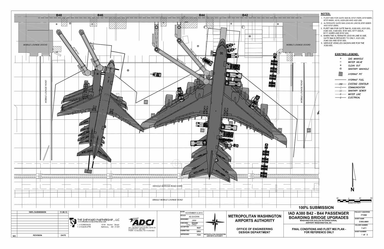
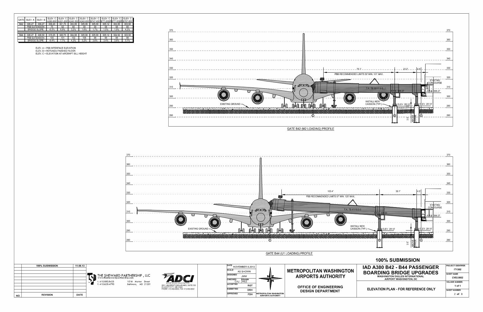
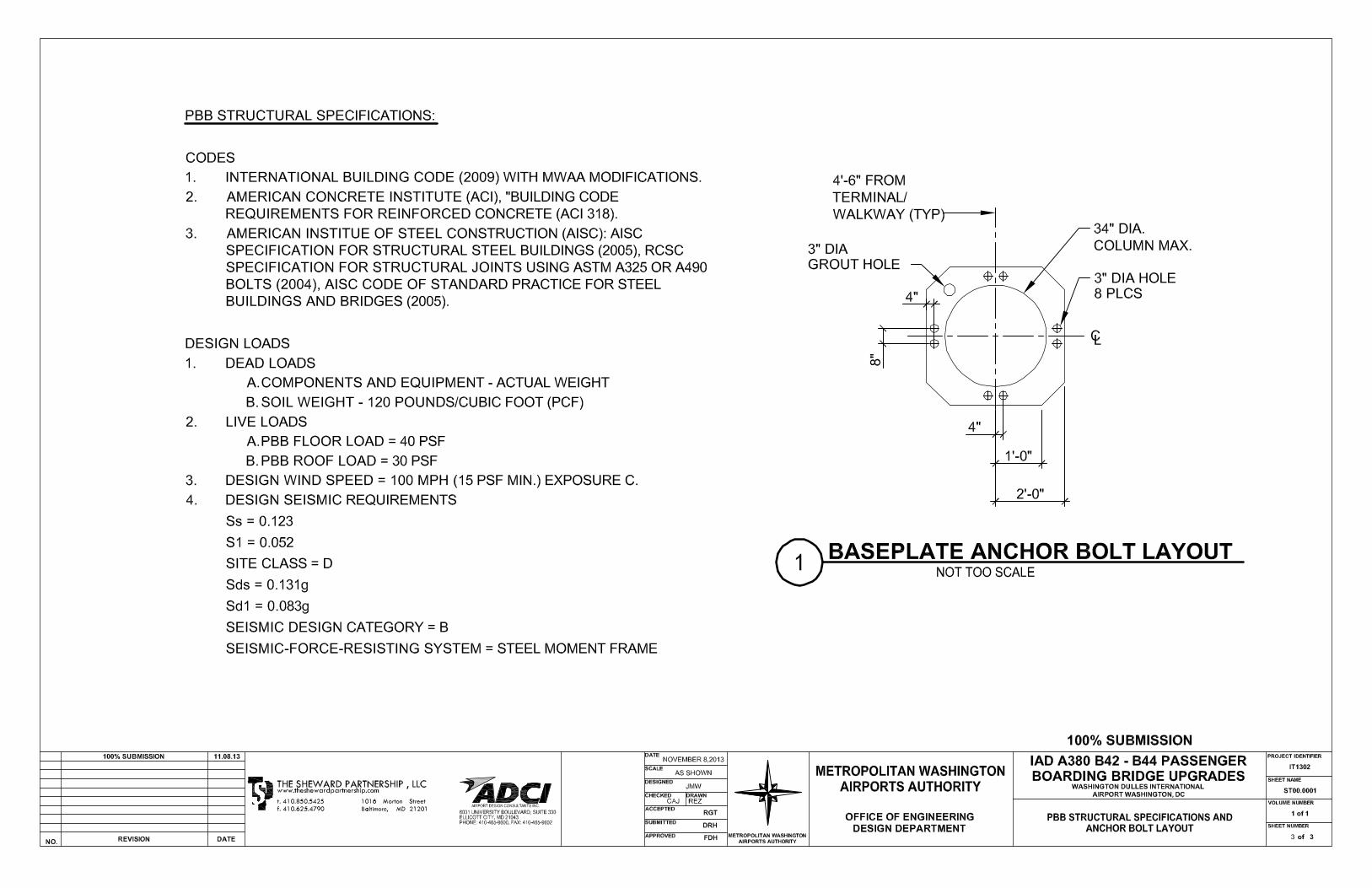
WASHINGTON DULLES INTERNATIONAL AIRPORT IAD IT1302
A380 B42/44 PASSENGER BOARDING BRIDGE UPGRADES NOVEMBER 8, 2013
APPENDIX II – ADDITIONAL DOG LEG REQUIREMENTS
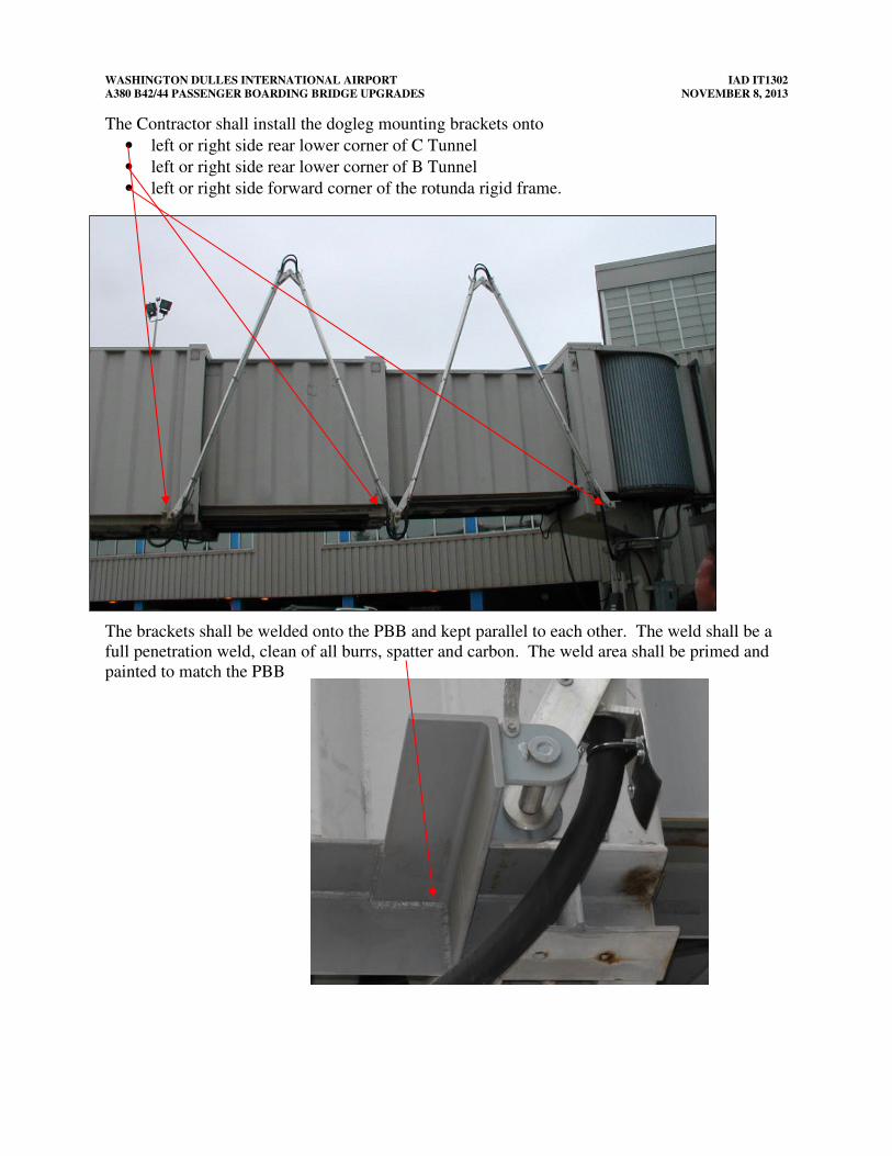
WASHINGTON DULLES INTERNATIONAL AIRPORT IAD IT1302
A380 B42/44 PASSENGER BOARDING BRIDGE UPGRADES NOVEMBER 8, 2013
The Contractor shall install the dogleg mounting brackets onto
• left or right side rear lower corner of C Tunnel
• left or right side rear lower corner of B Tunnel
• left or right side forward corner of the rotunda rigid frame.
The brackets shall be welded onto the PBB and kept parallel to each other. The weld shall be a
full penetration weld, clean of all burrs, spatter and carbon. The weld area shall be primed and
painted to match the PBB
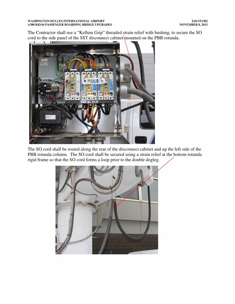
WASHINGTON DULLES INTERNATIONAL AIRPORT IAD IT1302
A380 B42/44 PASSENGER BOARDING BRIDGE UPGRADES NOVEMBER 8, 2013
The Contractor shall use a “Kellum Grip” threaded strain relief with bushing, to secure the SO
cord to the side panel of the SST disconnect cabinet mounted on the PBB rotunda.
The SO cord shall be routed along the rear of the disconnect cabinet and up the left side of the
PBB rotunda column. The SO cord shall be secured using a strain relief at the bottom rotunda
rigid frame so that the SO cord forms a loop prior to the double dogleg.
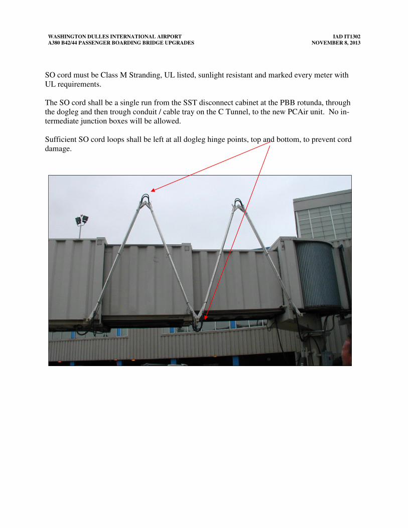
WASHINGTON DULLES INTERNATIONAL AIRPORT IAD IT1302
A380 B42/44 PASSENGER BOARDING BRIDGE UPGRADES NOVEMBER 8, 2013
SO cord must be Class M Stranding, UL listed, sunlight resistant and marked every meter with
UL requirements.
The SO cord shall be a single run from the SST disconnect cabinet at the PBB rotunda, through
the dogleg and then trough conduit / cable tray on the C Tunnel, to the new PCAir unit. No in-
termediate junction boxes will be allowed.
Sufficient SO cord loops shall be left at all dogleg hinge points, top and bottom, to prevent cord
damage.
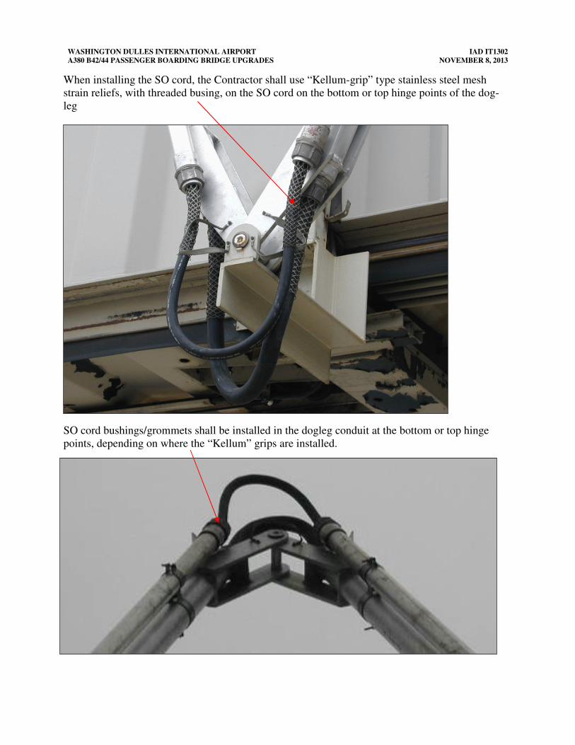
WASHINGTON DULLES INTERNATIONAL AIRPORT IAD IT1302
A380 B42/44 PASSENGER BOARDING BRIDGE UPGRADES NOVEMBER 8, 2013
When installing the SO cord, the Contractor shall use “Kellum-grip” type stainless steel mesh
strain reliefs, with threaded busing, on the SO cord on the bottom or top hinge points of the dog-
leg
.
SO cord bushings/grommets shall be installed in the dogleg conduit at the bottom or top hinge
points, depending on where the “Kellum” grips are installed.
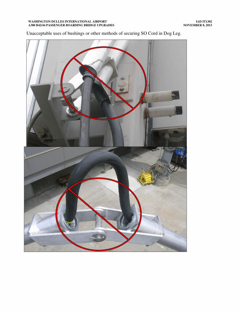
WASHINGTON DULLES INTERNATIONAL AIRPORT IAD IT1302
A380 B42/44 PASSENGER BOARDING BRIDGE UPGRADES NOVEMBER 8, 2013
Unacceptable uses of bushings or other methods of securing SO Cord in Dog Leg.
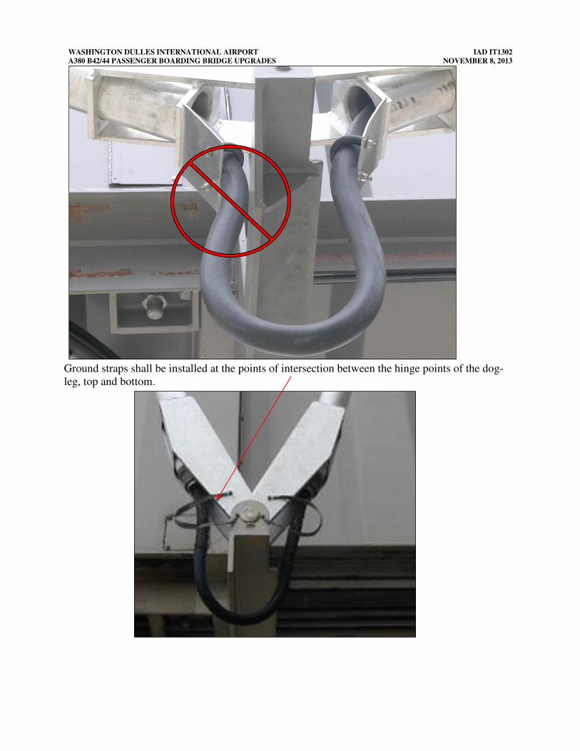
WASHINGTON DULLES INTERNATIONAL AIRPORT IAD IT1302
A380 B42/44 PASSENGER BOARDING BRIDGE UPGRADES NOVEMBER 8, 2013
Ground straps shall be installed at the points of intersection between the hinge points of the dog-
leg, top and bottom.
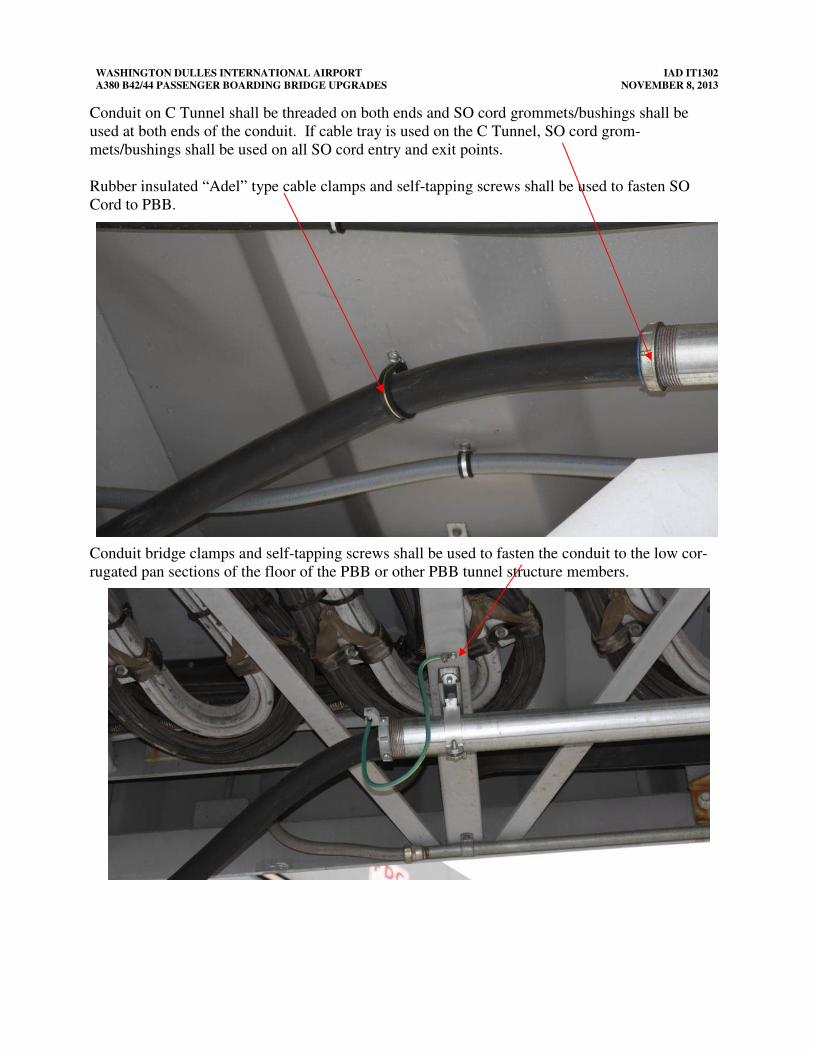
WASHINGTON DULLES INTERNATIONAL AIRPORT IAD IT1302
A380 B42/44 PASSENGER BOARDING BRIDGE UPGRADES NOVEMBER 8, 2013
Conduit on C Tunnel shall be threaded on both ends and SO cord grommets/bushings shall be
used at both ends of the conduit. If cable tray is used on the C Tunnel, SO cord grom-
mets/bushings shall be used on all SO cord entry and exit points.
Rubber insulated “Adel” type cable clamps and self-tapping screws shall be used to fasten SO
Cord to PBB.
Conduit bridge clamps and self-tapping screws shall be used to fasten the conduit to the low cor-
rugated pan sections of the floor of the PBB or other PBB tunnel structure members.