Embed Size (px)
Citation preview
2
Congratulations for selecting HyChill Hydrocarbon Refrigerant –
a high performance refrigerant that is climate friendly.
The Consumer benefits from certain warranties and conditions implied by
Federal and State legislation. By law these benefits cannot be withheld.
This warranty offers the following benefits to consumers in addition to, and
without restricting in any way, the benefits conferred by law. This warranty
shall be read in conjunction with consumer rights at law
This warranty is for a period of twelve months from date of installation of
the HyChill Refrigerant and is limited to replacement of the refrigerant or
reimbursement of the purchase price, at HyChill’s discretion.
Consequential losses are expressly excluded.
Where the customer believes there is a fault with the refrigerant, the remainder
of the refrigerant in the supplied container must be returned to HyChill in
order for the customer to be eligible for replacement or reimbursement.
Freight and insurance for the return of the refrigerant and container is at
the customers expense. If HyChill elects to replace the product, freight and
insurance of the replacement will be borne by HyChill..
Fitness for purpose of the supplied refrigerant is ultimately the responsibility
of the installer, as they are the only person(s) able to assess the specific
application in sufficient detail.
Warranty registration cardEquipment: __________________________________________________
Serial No. ____________________________________________________
Customer Name: _____________________________________________
Date of Installation: ___________________________________________
Place of Installation: ___________________________________________ HyChill Refrigerants85A Canterbury Road, Kilsyth Vic 3137 AustraliaTelephone: +61 (3) 9761 8788 Facsimile: +61 (3) 9761 8799Email: [email protected]: www.hychill.com
Please photocopy completed form and fax to HyChill Australia Pty Ltd on +61-3-9761 8799
AB
OU
T U
S
WARRANTY ~ GUARANTEE
3
BA
CK
GR
OU
ND
IN
FO
RM
ATIO
NA
BO
UT U
S
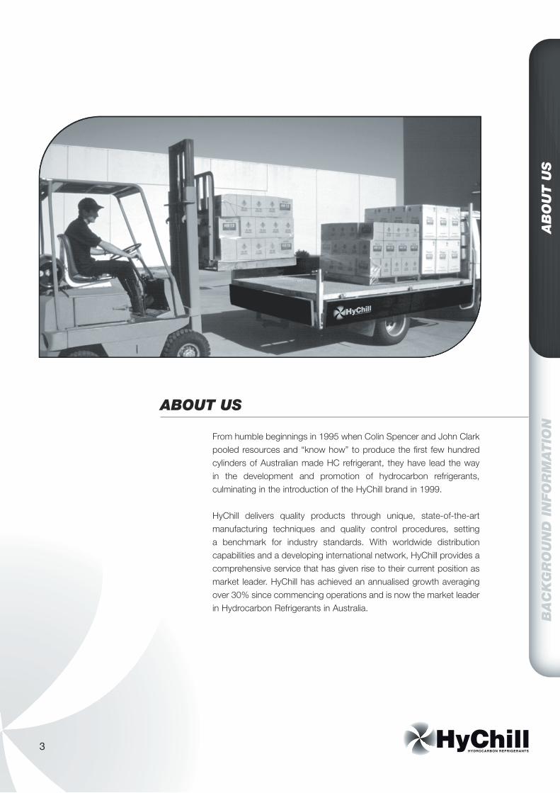
From humble beginnings in 1995 when Colin Spencer and John Clark pooled resources and “know how” to produce the first few hundred cylinders of Australian made HC refrigerant, they have lead the way in the development and promotion of hydrocarbon refrigerants, culminating in the introduction of the HyChill brand in 1999. HyChill delivers quality products through unique, state-of-the-art manufacturing techniques and quality control procedures, setting a benchmark for industry standards. With worldwide distribution capabilities and a developing international network, HyChill provides a comprehensive service that has given rise to their current position as market leader. HyChill has achieved an annualised growth averaging over 30% since commencing operations and is now the market leader in Hydrocarbon Refrigerants in Australia.
ABOUT US
4
BA
CK
GR
OU
ND
IN
FO
RM
ATIO
NTH
E B
EN
EFIT
S O
F H
C R
EFR
IGE
RA
NTS
HyChill’s hydrocarbons deliver a huge array of benefits to the environment and to the consumer. Created by nature, not by a chemical company, hydrocarbons cannot be patented, keeping them affordable and available to everyone. They have an atmospheric life of less than one year with no effect on the ozone layer and virtually no contribution to global warming. Many important qualities found in HyChill product’s make them an extremely efficient and reliable choice for most air conditioning and refrigeration systems.
THE BENEFITS OF HC REFRIGERANTS
5
BA
CK
GR
OU
ND
IN
FO
RM
ATIO
NTH
E B
EN
EFIT
S O
F H
C R
EFR
IGE
RA
NTS
Use of existing charging equipment:The equipment currently used for existing refrigerants requires no modification or change for charging hydrocarbon refrigerants.
Since no retrofitting is required, HyChill refrigerants are the perfect "drop in" solution for systems, which previously used gases such as CFC R12, HFC R134a, HCFC R22, R502, R11 and others.
Less Energy Use Hydrocarbon refrigerants in refrigeration or car air-conditioning systems use less energy than fluorocarbon refrigerants.
This provides a number of benefits: • Operating costs are lower. • Compressor loads are reduced, which reduces wear and tear, extending component life and reducing leakage. • Less energy consumed means less fossil fuel burned resulting in lower global warming.
Increased Safety Most importantly, the safety of hydrocarbon refrigerants is assured when the application complies with relevant safety standards, such as International Standards ISO 5149, BS 4434-1995, and Australia/New Zealand Standard AS/NZS 1677-1998.
Research Hydrocarbon refrigerants have been the subject of detailed studies by many organisations including:
• Minus 40 Refrigeration Consultants & Design Engineers • INFRAS - Chennai, Pondicherri, India • Swiss Contact S.M.E.P. - Indonesia, India, Sri Lanka • Natural Refrigerants Transition Board• Arthur D Little - Risk Assessment Study Engineers
• Granherne P/L - Risk Assessment Study Engineers• Maclaine-cross, I. L., Usage and Risk
of Hydrocarbon Refrigerants in Motor Cars for Australia and the United States, June 2004, International Journal of Refrigeration, Volume 27, No. 4, pages 339-345
Conclusions of these organisations support the continued growth in the use and acceptance of hydrocarbon refrigerants.
Scientific papers published by various organisations in Australia and overseas, repeatedly attest to the efficiency and safety of hydrocarbon refrigerants across a wide range of applications.
Great Heat Conductors Hydrocarbons are also 50% more efficient conductors of heat than fluorocarbons.
In practical terms this means that the hydrocarbon molecule rejects heat faster than a fluorocarbon molecule.
For example, a Coca Cola or Pepsi drink cabinet which uses HyChill Minus 30 hydrocarbon refrigerant instead of HFC R134a, chills the cans to the desired temperature approximately 15% to 30% faster. In the summer time with higher volume store traffic, this is a definate advantage for the store owner, as well as for the manufacturer of the products being sold.
Use Less Gas HyChill hydrocarbon refrigerants have a unique advantage, each kilogram of hydrocarbon refrigerant replaces 3 kilograms of fluorocarbon refrigerant, so you only require a third of the refrigerant by weight.
6
BA
CK
GR
OU
ND
IN
FO
RM
ATIO
NTH
E M
AR
KE
T
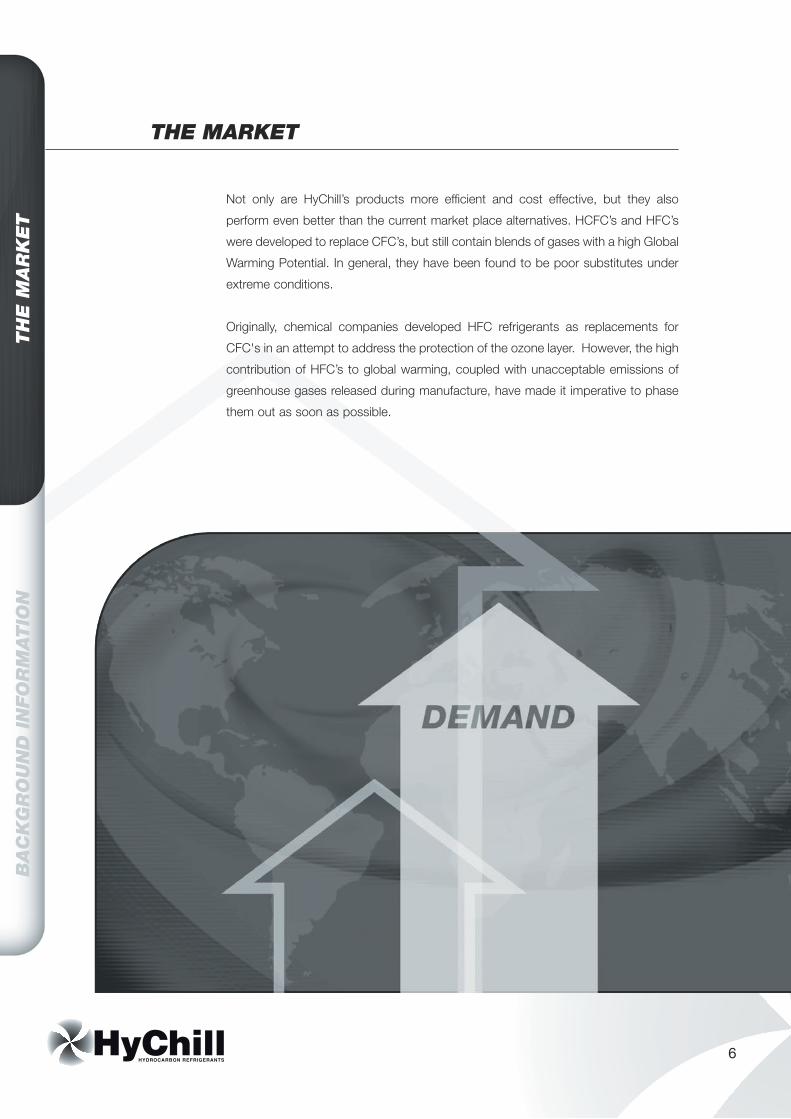
Not only are HyChill’s products more efficient and cost effective, but they also
perform even better than the current market place alternatives. HCFC’s and HFC’s
were developed to replace CFC’s, but still contain blends of gases with a high Global
Warming Potential. In general, they have been found to be poor substitutes under
extreme conditions.
Originally, chemical companies developed HFC refrigerants as replacements for
CFC's in an attempt to address the protection of the ozone layer. However, the high
contribution of HFC’s to global warming, coupled with unacceptable emissions of
greenhouse gases released during manufacture, have made it imperative to phase
them out as soon as possible.
THE MARKET
7
BA
CK
GR
OU
ND
IN
FO
RM
ATIO
NTH
E M
AR
KE
T
In general, HFC refrigerants were
found to be a poor substitute for CFC
refrigerants, as extensive modifications
to, or replacement of, existing systems
were necessary to facilitate their use. This
costly exercise was called retrofitting.
Furthermore, HFC's were found to be poor
performers under extreme conditions.
As these original HFC gases were found
to be unsuitable in many refrigeration
applications, it then became necessary
to create a large number of HFC/HCFC
combinations and other blends.
The importance of hydrocarbon refrigerants
had been extolled by Greenpeace under the
name "Greenfreeze Technology" for more
than twenty years. As each application
for alternative refrigerants was properly
studied, it was found that a hydrocarbon
refrigerant was available as the perfect
alternative. Often, no changes to system
design were required.
As a result, in 1991, Foron, a minor
German manufacturer of refrigerators,
was sponsored by Greenpeace to develop
a small refrigerator, which utilized the best
possible solutions for foam expansion and
in the refrigeration system. This project
advanced very quickly in the face of a
great deal of obstruction by fluorocarbon
refrigerant manufacturers and distributors.
In August 1992, the German mail order
company "Neckermann" placed an initial
order with Foron for 20,000 Greenfreeze
refrigerators. Within three months, the
quantity on order exceeded 50,000 units.
By the end of 1993, after enthusiastic
acceptance of Foron "Greenfreeze
Technology" at Europe’s most important
homewares exhibition, most of Germany's
major refrigerator manufacturers announced
that their production lines would adopt
hydrocarbon technology as a matter
of urgency.
By 1996, almost 100% of refrigerators
made for the German market were designed
to utilise "Greenfreeze Technology".
It’s no surprise therefore that an increasing
number of refrigeration systems are
being charged with HyChill hydrocarbon
refrigerants. The combination of first class
products and environmental responsibility
has propelled HyChill to grow in demand
- from distributors and suppliers, to
technicians and consumers.
8
BA
CK
GR
OU
ND
IN
FO
RM
ATIO
NE
XP
OR
T / D
ISTR
IBU
TIO
N
EXPORT
DISTRIBUTION
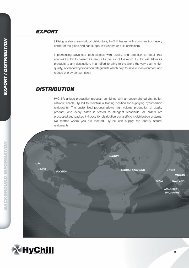
Utilizing a strong network of distributors, HyChill trades with countries from every corner of the globe and can supply in cylinders or bulk containers.
Implementing advanced technologies with quality and attention to detail that enables HyChill to present its service to the rest of the world. HyChill will deliver its products to any destination, in an effort to bring to the world the very best in high quality, advanced hydrocarbon refrigerants which help to save our environment and reduce energy consumption.
HyChill’s unique production process, combined with an accomplished distribution network enable HyChill to maintain a leading position for supplying hydrocarbon refrigerants. The customised process allows high volume production of quality product, and every batch is tested to stringent standards. All orders are processed and packed in-house for distribution using efficient distribution systems. No matter where you are located, HyChill can supply top quality natural refrigerants.
TEXAS
USA
FLORIDA
EUROPE
CHINA
TAIWAN
THAILAND
MALAYSIA
INDIA
MIDDLE EAST GCC
SINGAPORE

9
BA
CK
GR
OU
ND
IN
FO
RM
ATIO
NSU
PP
OR
T
JAPAN
PHILIPPINES
INDONESIA
SUPPORT
What makes HyChill unique, apart from its range of products, is the standard of after-care support - that famous HyChill service. It’s all about customer satisfaction!
Friendly staff and experienced representatives are on hand for advice and always ready to assist. Comprehensive information is readily available for both the trade and consumers. These include:• Product information brochures and leaflets.• Information Manual covering all technical requirements.• Interactive CD Roms• A comprehensive website covering everything from products, to environmental
trends, research and technical data. Check out www.hychill.com.au
You can rely on HyChill to set new industry standards in total customer satisfaction.
TAIWAN
THAILAND
10
It’s all about ‘Customer Satisfaction’
When you service your customers’ air conditioner with highly efficient Minus 30 hydrocarbon refrigerant from HyChill, you are enhancing the most important component of your business: ‘Customer Satisfaction.’
Minus 30 refrigerant is a highly efficient heat transfer medium; it uses about 30% less energy to produce a faster result. On really hot days, Minus 30 will put a smile on your customers’ face. Contented customers guarantee the growth of your business.
We supply product at an attractive price - it’s easy to see that Minus 30 is the lowest cost alternative to HFC refrigerants when you are only required to use 1/3 of R134a’s charge weight, or about 85% by volume.
Each standard 22 litre cylinder will hold 9kgs of Minus 30 as opposed to 20kgs for R134a, this means you are only paying for 9kgs of refrigerant and not 20kgs. Furthermore, each 9kgs of Minus 30 will charge 30 or more systems whereas 20kgs of R134a will only charge about 25 systems.
You can use your normal equipment; Minus 30 is suitable for all systems. It doesn’t matter whether it is an old R12 system, or a new R134a system, Minus 30 is compatible with all oils, O Rings, Seals and Gaskets. We highly recommend the use of modern service equipment, scales and diagnostic tools, they save time and money, and, they help to build your customers’ confidence. We also recommend HyChill SRO 500 Synthetic Refrigerant oil, in systems and in your vacuum pump. It is non hygroscopic and is compatible with all refrigerants.
Old systems need to be serviced with a complete understanding that a "gas-up" will not fix faults! Your diagnostic skills are so essential. If you have a system, which just won’t work, call us, if we don’t know the answer we will research it for you, quickly! If you are unfamiliar with hydrocarbon refrigerants, we would appreciate you ringing for advice. Meanwhile, a free information manual is available, please indicate on your order if you require copies, or just phone us and we will mail one to you. A refrigerant charge weights list is avaiable for most systems.
Your goal is the same as ours, and the desired outcome is identical:
‘Customer Satisfaction’
HyChill Refrigerants, the Natural Alternative
11
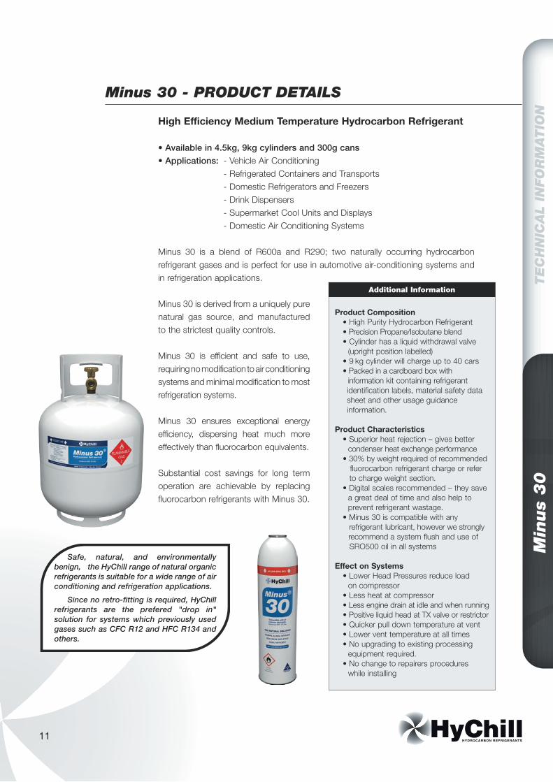
High Efficiency Medium Temperature Hydrocarbon Refrigerant
• Available in 4.5kg, 9kg cylinders and 300g cans• Applications: - Vehicle Air Conditioning - Refrigerated Containers and Transports - Domestic Refrigerators and Freezers - Drink Dispensers - Supermarket Cool Units and Displays - Domestic Air Conditioning Systems
Minus 30 is a blend of R600a and R290; two naturally occurring hydrocarbon refrigerant gases and is perfect for use in automotive air-conditioning systems and in refrigeration applications.
Minus 30 is derived from a uniquely pure natural gas source, and manufactured to the strictest quality controls.
Minus 30 is efficient and safe to use, requiring no modification to air conditioning systems and minimal modification to most refrigeration systems.
Minus 30 ensures exceptional energy efficiency, dispersing heat much more effectively than fluorocarbon equivalents.
Substantial cost savings for long term operation are achievable by replacing fluorocarbon refrigerants with Minus 30.
Min
us
30
TE
CH
NIC
AL
INFO
RM
ATIO
N
Minus 30 - PRODUCT DETAILS
Product Composition • High Purity Hydrocarbon Refrigerant • Precision Propane/Isobutane blend • Cylinder has a liquid withdrawal valve (upright position labelled) • 9 kg cylinder will charge up to 40 cars • Packed in a cardboard box with information kit containing refrigerant identification labels, material safety data sheet and other usage guidance information.
Product Characteristics • Superior heat rejection – gives better condenser heat exchange performance • 30% by weight required of recommended fluorocarbon refrigerant charge or refer to charge weight section. • Digital scales recommended – they save a great deal of time and also help to prevent refrigerant wastage. • Minus 30 is compatible with any refrigerant lubricant, however we strongly recommend a system flush and use of SRO500 oil in all systems
Effect on Systems • Lower Head Pressures reduce load on compressor • Less heat at compressor • Less engine drain at idle and when running • Positive liquid head at TX valve or restrictor • Quicker pull down temperature at vent • Lower vent temperature at all times • No upgrading to existing processing equipment required. • No change to repairers procedures while installing
Additional Information
Safe, natural, and environmentally benign, the HyChill range of natural organic refrigerants is suitable for a wide range of air conditioning and refrigeration applications.
Since no retro-fitting is required, HyChill refrigerants are the prefered "drop in" solution for systems which previously used gases such as CFC R12 and HFC R134 and others.
Min
us
30
TE
CH
NIC
AL
INFO
RM
ATIO
N
12
TE
CH
NIC
AL
INFO
RM
ATIO
N
The following pages are designed to assist in the step by step servicing and diagnosis of air conditioning systems.
SAFETY PRECAUTIONSRefrigerants have a very low boiling point. Extreme care must be taken when they are being handled. Always observe the following safety precautions:
• Always wear eye protection • Wear gloves • Don’t allow liquid refrigerant to contact the bare skin, as this can cause
frost bite • Don’t heat containers of refrigerant • Provide adequate ventilation when charging or recovering refrigerant as they are heavier than air • Use caution when steam cleaning around A/C components as hot water on
the pipes and tubing could cause damage due to thermal expansion of the refrigerant contained within them
• Avoid breathing refrigerant vapour • If pumping refrigerant into a cylinder, do not allow the cylinder to be filled to
more than 80% of its capacity, as the remaining 20% is necessary to allow for any thermal expansion of the refrigerant
• Always recover all fluorocarbon refrigerants
PREPARATIONThe following preliminary checks should be carried out prior to any service or diagnosis of an air conditioning system:
• Check for visible damage or chaffing of the hoses • Ensure the condenser fins are not blocked with debris such as insects, leaves etc. and that the fins are straight • Ensure that the condenser fan operates and runs in the correct direction • Check that the engine and radiator are at the correct operating temperature
and are not overheating • Inspect the drive belts for damage and correct tension • Ensure that the engine viscous fan engages at the correct temperature. • The compressor should cycle on and off • Make sure the evaporator drain hose is not blocked • The heater is turned off and in the full cold mode position • The air mix door is fully closed • A/C switch fully illuminates when engaged • There are no vacuum hose leaks • The dash vents should open and close fully • There must be no air leaks between the evaporator case and the heater case • The blower fan should be operational on all speeds • Check for any evidence of refrigerant leakage and oil staining at components
and connections
A GUIDE TO AIR CONDITIONING SERVICE AND DIAGNOSIS
13
Min
us
30
TE
CH
NIC
AL
INFO
RM
ATIO
N
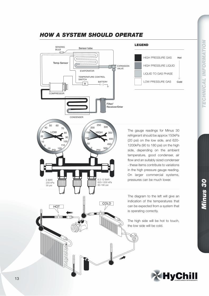
The gauge readings for Minus 30 refrigerant should be approx 150kPa (20 psi) on the low side, and 620-1200kPa (90 to 180 psi) on the high side, depending on the ambient temperature, good condenser, air flow and an suitably sized condenser - these items contribute to variations in the high pressure gauge reading. On larger commercial systems, pressures can be much lower.
The diagram to the left will give an indication of the temperatures that can be expected from a system that is operating correctly.
The high side will be hot to touch, the low side will be cold.
HOW A SYSTEM SHOULD OPERATE
-100
10
20
3040
50 607080
PSI
LOW
050
100
150
200250
300
PSI
HIGH 350
90100
110120
400
450500
2 BAR200 kPa30 psi
6.2-12 BAR620-1200 kPa90-180 psi
LEGEND
HIGH PRESSURE GAS
HIGH PRESSURE LIQUID
LIQUID TO GAS PHASE
LOW PRESSURE GAS
Hot
Cold
Min
us
30
TE
CH
NIC
AL
INFO
RM
ATIO
N
14
TE
CH
NIC
AL
INFO
RM
ATIO
N
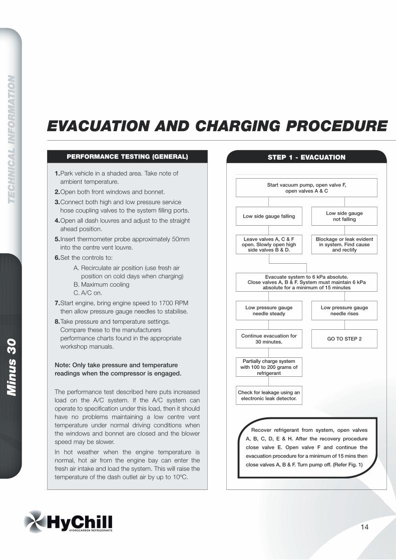
EVACUATION AND CHARGING PROCEDURE
1. Park vehicle in a shaded area. Take note of ambient temperature.
2. Open both front windows and bonnet.
3. Connect both high and low pressure service hose coupling valves to the system filling ports.
4. Open all dash louvres and adjust to the straight ahead position.
5. Insert thermometer probe approximately 50mm into the centre vent louvre.
6. Set the controls to:
A. Recirculate air position (use fresh air position on cold days when charging) B. Maximum cooling C. A/C on.
7. Start engine, bring engine speed to 1700 RPM then allow pressure gauge needles to stabilise.
8. Take pressure and temperature settings. Compare these to the manufacturers performance charts found in the appropriate workshop manuals.
Note: Only take pressure and temperature readings when the compressor is engaged.
The performance test described here puts increased load on the A/C system. If the A/C system can operate to specification under this load, then it should have no problems maintaining a low centre vent temperature under normal driving conditions when the windows and bonnet are closed and the blower speed may be slower.
In hot weather when the engine temperature is normal, hot air from the engine bay can enter the fresh air intake and load the system. This will raise the temperature of the dash outlet air by up to 10ºC.
PERFORMANCE TESTING (GENERAL)
Start vacuum pump, open valve F,open valves A & C
Low side gauge falling Low side gauge not falling
Leave valves A, C & F open. Slowly open high
side valves B & D.
Evacuate system to 6 kPa absolute.Close valves A, B & F. System must maintain 6 kPa
absolute for a minimum of 15 minutes
Blockage or leak evident in system. Find cause
and rectify
Low pressure gauge needle steady
Low pressure gauge needle rises
Continue evacuation for 30 minutes.
Partially charge system with 100 to 200 grams of
refrigerant
Check for leakage using an electronic leak detector.
GO TO STEP 2
Recover refrigerant from system, open valves
A, B, C, D, E & H. After the recovery procedure
close valve E. Open valve F and continue the
evacuation procedure for a minimum of 15 mins then
close valves A, B & F. Turn pump off. (Refer Fig. 1)
STEP 1 - EVACUATION
15
Min
us
30
TE
CH
NIC
AL
INFO
RM
ATIO
N
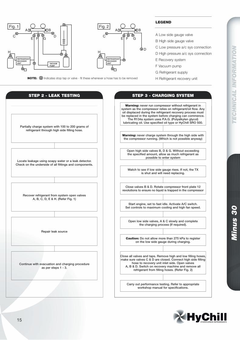
LEGEND
A Low side gauge valve
B High side gauge valve
C Low pressure a/c sys connection
D High pressure a/c sys connection
E Recovery system
F Vacuum pump
G Refrigerant supply
H Refrigerant recovery unit
STEP 3 - CHARGING SYSTEM
Warning: never run compressor without refrigerant in system as the compressor relies on refrigerant/oil flow. Any oil displaced during the refrigerant recovery process must be replaced in the system before charging can commence.
The R134a system uses P.A.G. (Polyalkylen glycol) lubricating oil. Use specified oil type or HyChill SRO 500.
Warning: never charge system through the high side with the compressor running. (Which is not possible anyway)
Open high side valves B, D & G. Without exceeding the specified amount, allow as much refrigerant as
possible to enter system
Watch to see if low side gauge rises. If not, the TX is shut and will need replacing.
Close valves B & D. Rotate compressor front plate 12 revolutions to ensure no liquid is trapped in the compressor
Start engine, set to fast idle. Activate A/C switch. Set controls to maximum cooling and high fan speed.
Open low side valves, A & C slowly and complete the charging process (If required).
Caution: Do not allow more than 275 kPa to register on the low side gauge during charging.
Carry out performance testing. Refer to appropriate workshop manual for specifications.
Close all valves and taps. Remove high and low filling hoses, make sure valves C & D are closed. Connect high side filling
hose to recovery unit inlet side. Open valves A, B & D. Switch on recovery machine and remove all
refrigerant from filling hoses. (Refer Fig. 2)
STEP 2 - LEAK TESTING
Partially charge system with 100 to 200 grams of refrigerant through high side filling hose.
Locate leakage using soapy water or a leak detector. Check on the underside of all fittings and components.
Recover refrigerant from system open valves A, B, C, D, E & H. (Refer Fig. 1)
Repair leak source
Continue with evacuation and charging procedure as per steps 1 - 3.
EVACUATION AND CHARGING PROCEDURE
Min
us
30
TE
CH
NIC
AL
INFO
RM
ATIO
N
16
TE
CH
NIC
AL
INFO
RM
ATIO
N
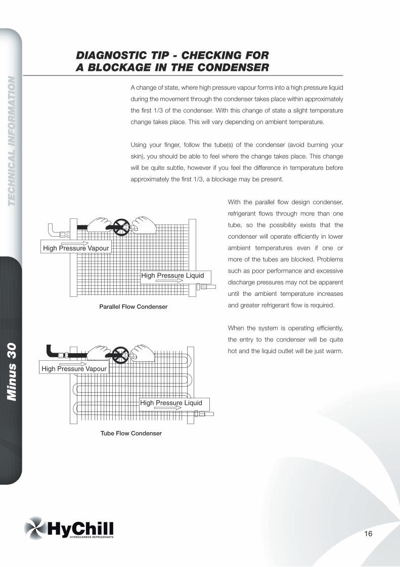
A change of state, where high pressure vapour forms into a high pressure liquid
during the movement through the condenser takes place within approximately
the first 1/3 of the condenser. With this change of state a slight temperature
change takes place. This will vary depending on ambient temperature.
Using your finger, follow the tube(s) of the condenser (avoid burning your
skin), you should be able to feel where the change takes place. This change
will be quite subtle, however if you feel the difference in temperature before
approximately the first 1/3, a blockage may be present.
With the parallel flow design condenser,
refrigerant flows through more than one
tube, so the possibility exists that the
condenser will operate efficiently in lower
ambient temperatures even if one or
more of the tubes are blocked. Problems
such as poor performance and excessive
discharge pressures may not be apparent
until the ambient temperature increases
and greater refrigerant flow is required.
When the system is operating efficiently,
the entry to the condenser will be quite
hot and the liquid outlet will be just warm.
DIAGNOSTIC TIP - CHECKING FOR A BLOCKAGE IN THE CONDENSER
17
Min
us
30
TE
CH
NIC
AL
INFO
RM
ATIO
N
WHY DO COMPRESSORS FAIL?
In the case of excessive head pressure the three reasons for this are:
BLOCKAGE IN SYSTEM - Check dryer, T.X. Valve, Condenser (internally)
OVERCHARGE IN THE SYSTEM - Some compressors are extremely susceptible to this
OVERPRESSURE IN THE SYSTEM - Inadequate car cooling system, clogged condenser fins (external), defective thermo fan or fan clutch, excessive moisture in system, a cocktail of refrigerants.
In most cases the reason you are fitting a reconditioned and guaranteed compressor is that the old or original compressor has "GONE DOWN", therefore you must ask yourself why did this happen?
Compressors do not fail for unexplained reasons so be assured that if you fit a compressor without answering the "WHY" question and without following the correct installation procedure this compressor will also "GO DOWN" causing you unnecessary losses in both time and money. So, why did the old unit fail?
Once you have found and rectified the reason for the old compressor failure, follow this procedure for the installation of the new unit to ensure trouble free running.
1. FLUSH THE SYSTEM 2-3 TIMES WITH HyChill ECO-FLUSH
It cannot be stressed strongly enough that if a compressor has had a burnout depositing sludge and debris through the system, this sludge will simply work its way back to the compressor if it is not removed.
2. REPLACE T.X. VALVE
3. REPLACE RECEIVER DRYER
4. EVACUATE SYSTEM FOR CHARGING AND TESTING
• When compressor oil is replaced it should match the refrigerant to be used.• HyChill SRO 500 lubricant is compatible with all refrigerants. • HyChill Minus 30 Refrigerant is compatible with most commonly used oils.
2. LACK OF OIL
In the case of lack of oil the two reasons for this are:
SYSTEM BLOCKAGE - restrictive flow of oil back to the compressor (i.e. tx valve, receiver/dryer, condenser, freezing evaporator)
SYSTEM LEAK - allowing the oil to escape from the system.
3. LACK OF REFRIGERANT (COMPRESSOR OVERHEATS)
Slow leaks allow the system to run with
low liquid supply to tx valve. The suction
return gas to the compressor is not cold
enough to cool the compressor parts
internally. Shaft seals harden and leak,
oil deteriorates and metal parts fail.
The three most likely causes for compressors to seize are:
1. EXCESSIVE HEAD PRESSURE
Min
us
30
TE
CH
NIC
AL
INFO
RM
ATIO
N
18
TE
CH
NIC
AL
INFO
RM
ATIO
N
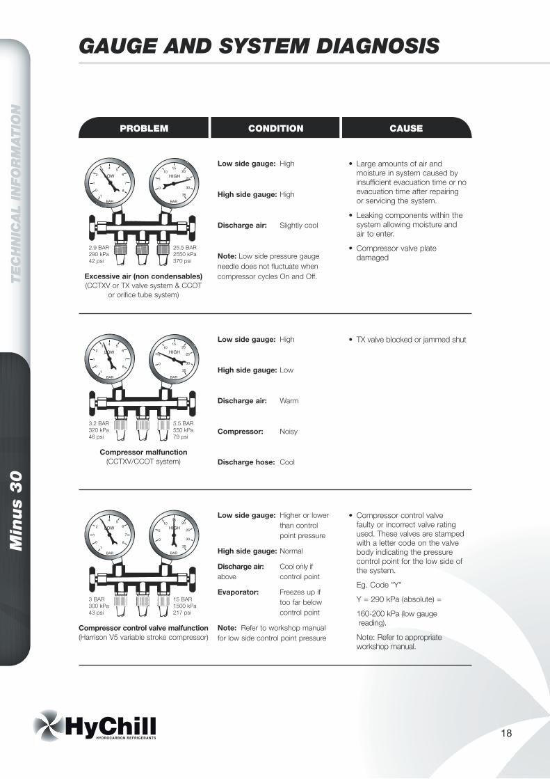
GAUGE AND SYSTEM DIAGNOSIS
Low side gauge: High
High side gauge: High
Discharge air: Slightly cool
Note: Low side pressure gauge needle does not fluctuate when compressor cycles On and Off.
• Large amounts of air and moisture in system caused by insufficient evacuation time or no evacuation time after repairing or servicing the system.
• Leaking components within the system allowing moisture and air to enter.
• Compressor valve plate damaged
Excessive air (non condensables)(CCTXV or TX valve system & CCOT
or orifice tube system)
Low side gauge: High
High side gauge: Low
Discharge air: Warm
Compressor: Noisy
Discharge hose: Cool
• TX valve blocked or jammed shut
Compressor malfunction(CCTXV/CCOT system)
Low side gauge: Higher or lower than control point pressure
High side gauge: Normal
Discharge air: Cool only if above control point
Evaporator: Freezes up if too far below control point
Note: Refer to workshop manual for low side control point pressure
• Compressor control valve faulty or incorrect valve rating used. These valves are stamped with a letter code on the valve body indicating the pressure control point for the low side of the system.
Eg. Code "Y"
Y = 290 kPa (absolute) =
160-200 kPa (low gauge reading).
Note: Refer to appropriate workshop manual.
Compressor control valve malfunction(Harrison V5 variable stroke compressor)
2.9 BAR290 kPa42 psi
25.5 BAR2550 kPa370 psi
3.2 BAR320 kPa46 psi
5.5 BAR550 kPa79 psi
3 BAR300 kPa43 psi
15 BAR1500 kPa217 psi
PROBLEM CONDITION CAUSE
19
Min
us
30
TE
CH
NIC
AL
INFO
RM
ATIO
N
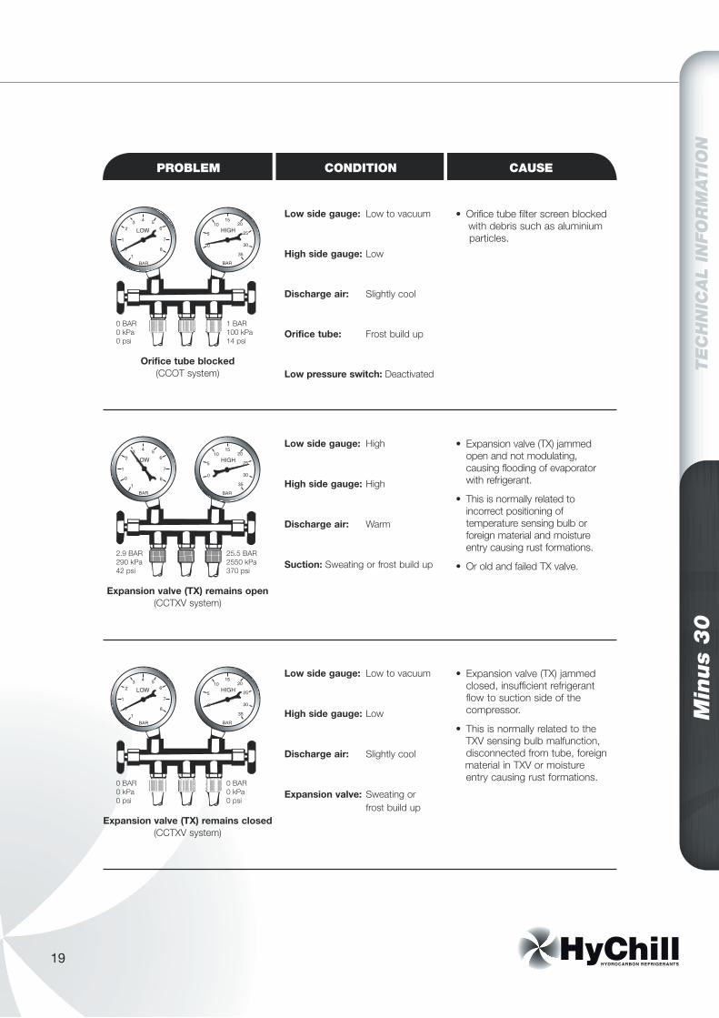
PROBLEM CONDITION CAUSE
Low side gauge: Low to vacuum
High side gauge: Low
Discharge air: Slightly cool
Orifice tube: Frost build up
Low pressure switch: Deactivated
• Orifice tube filter screen blocked with debris such as aluminium particles.
Orifice tube blocked(CCOT system)
Low side gauge: High
High side gauge: High
Discharge air: Warm
Suction: Sweating or frost build up
• Expansion valve (TX) jammed open and not modulating, causing flooding of evaporator with refrigerant.
• This is normally related to incorrect positioning of temperature sensing bulb or foreign material and moisture entry causing rust formations.
• Or old and failed TX valve.
Expansion valve (TX) remains open (CCTXV system)
Low side gauge: Low to vacuum
High side gauge: Low
Discharge air: Slightly cool
Expansion valve: Sweating or frost build up
• Expansion valve (TX) jammed closed, insufficient refrigerant flow to suction side of the compressor.
• This is normally related to the TXV sensing bulb malfunction, disconnected from tube, foreign material in TXV or moisture entry causing rust formations.
Expansion valve (TX) remains closed (CCTXV system)
0 BAR0 kPa0 psi
1 BAR100 kPa14 psi
2.9 BAR290 kPa42 psi
25.5 BAR2550 kPa370 psi
0 BAR0 kPa0 psi
0 BAR0 kPa0 psi
Min
us
30
TE
CH
NIC
AL
INFO
RM
ATIO
N
20
TE
CH
NIC
AL
INFO
RM
ATIO
N
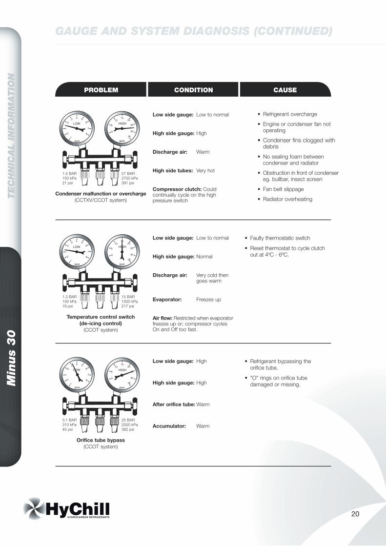
GAUGE AND SYSTEM DIAGNOSIS (CONTINUED)
PROBLEM CONDITION CAUSE
Low side gauge: Low to normal
High side gauge: High
Discharge air: Warm
High side tubes: Very hot
Compressor clutch: Could continually cycle on the high pressure switch
• Refrigerant overcharge
• Engine or condenser fan not operating
• Condenser fins clogged with debris
• No sealing foam between condenser and radiator
• Obstruction in front of condenser eg. bullbar, insect screen
• Fan belt slippage
• Radiator overheatingCondenser malfunction or overcharge
(CCTXV/CCOT system)
Low side gauge: Low to normal
High side gauge: Normal
Discharge air: Very cold then goes warm
Evaporator: Freezes up
Air flow: Restricted when evaporator freezes up or; compressor cycles On and Off too fast.
• Faulty thermostatic switch
• Reset thermostat to cycle clutch out at 4ºC - 6ºC.
Temperature control switch(de-icing control)
(CCOT system)
Low side gauge: High
High side gauge: High
After orifice tube: Warm
Accumulator: Warm
• Refrigerant bypassing the orifice tube.
• "O" rings on orifice tube damaged or missing.
Orifice tube bypass(CCOT system)
1.5 BAR150 kPa21 psi
27 BAR2700 kPa391 psi
1.3 BAR130 kPa19 psi
15 BAR1500 kPa217 psi
3.1 BAR310 kPa45 psi
25 BAR2500 kPa362 psi
21
Min
us
30
TE
CH
NIC
AL
INFO
RM
ATIO
N
PROBLEM CONDITION CAUSE
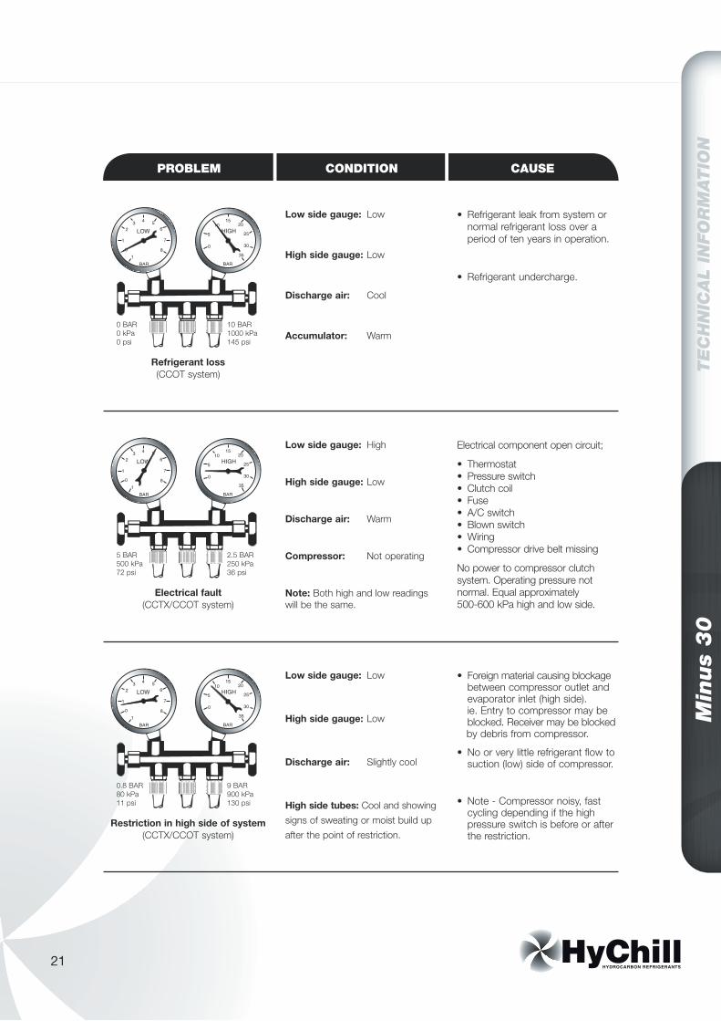
Low side gauge: Low
High side gauge: Low
Discharge air: Cool
Accumulator: Warm
• Refrigerant leak from system or normal refrigerant loss over a period of ten years in operation.
• Refrigerant undercharge.
Refrigerant loss(CCOT system)
Low side gauge: High
High side gauge: Low
Discharge air: Warm
Compressor: Not operating
Note: Both high and low readings will be the same.
Electrical component open circuit;
• Thermostat • Pressure switch • Clutch coil • Fuse • A/C switch • Blown switch • Wiring • Compressor drive belt missing
No power to compressor clutch system. Operating pressure not normal. Equal approximately 500-600 kPa high and low side.
Electrical fault(CCTX/CCOT system)
Low side gauge: Low
High side gauge: Low
Discharge air: Slightly cool
High side tubes: Cool and showing signs of sweating or moist build up after the point of restriction.
• Foreign material causing blockage between compressor outlet and evaporator inlet (high side). ie. Entry to compressor may be blocked. Receiver may be blocked by debris from compressor.
• No or very little refrigerant flow to suction (low) side of compressor.
• Note - Compressor noisy, fast cycling depending if the high pressure switch is before or after the restriction.
Restriction in high side of system(CCTX/CCOT system)
0 BAR0 kPa0 psi
10 BAR1000 kPa145 psi
5 BAR500 kPa72 psi
2.5 BAR250 kPa36 psi
0.8 BAR80 kPa11 psi
9 BAR900 kPa130 psi
Min
us
30
TE
CH
NIC
AL
INFO
RM
ATIO
N
22
TE
CH
NIC
AL
INFO
RM
ATIO
N
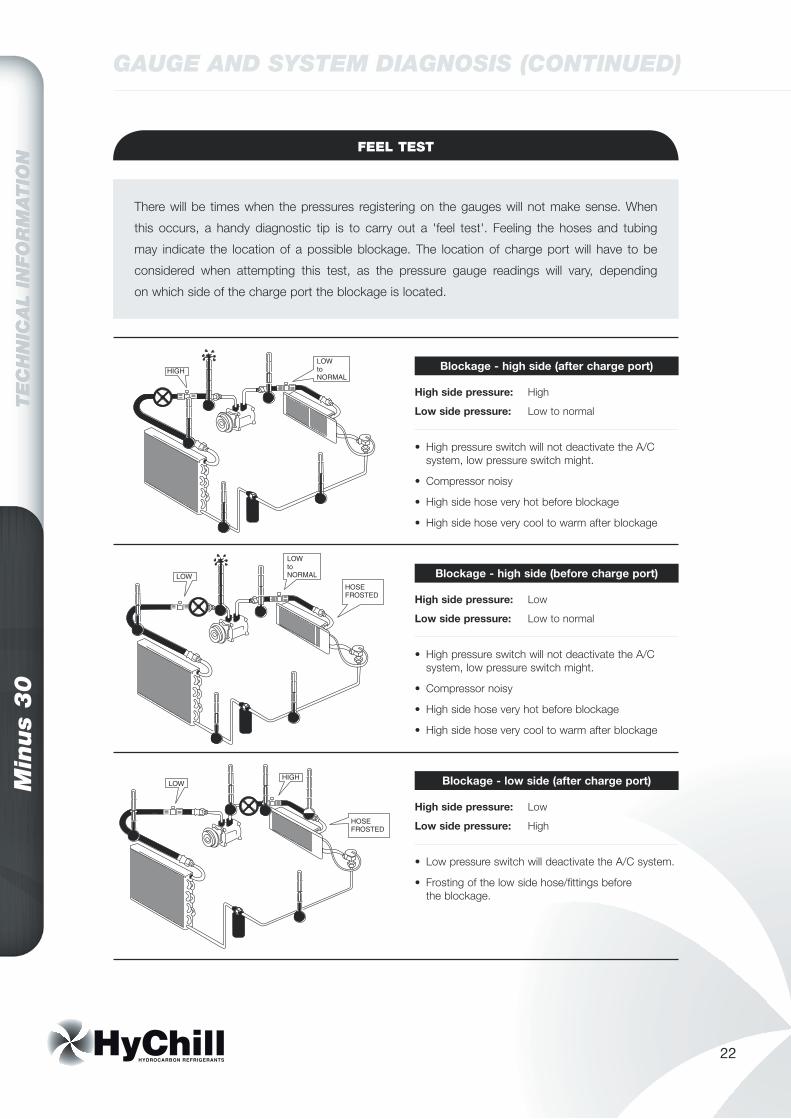
GAUGE AND SYSTEM DIAGNOSIS (CONTINUED)
FEEL TEST
High side pressure: High
Low side pressure: Low to normal
There will be times when the pressures registering on the gauges will not make sense. When
this occurs, a handy diagnostic tip is to carry out a 'feel test'. Feeling the hoses and tubing
may indicate the location of a possible blockage. The location of charge port will have to be
considered when attempting this test, as the pressure gauge readings will vary, depending
on which side of the charge port the blockage is located.
Blockage - high side (after charge port)
• High pressure switch will not deactivate the A/C system, low pressure switch might.
• Compressor noisy
• High side hose very hot before blockage
• High side hose very cool to warm after blockage
High side pressure: Low
Low side pressure: Low to normal
Blockage - high side (before charge port)
• High pressure switch will not deactivate the A/C system, low pressure switch might.
• Compressor noisy
• High side hose very hot before blockage
• High side hose very cool to warm after blockage
High side pressure: Low
Low side pressure: High
Blockage - low side (after charge port)
• Low pressure switch will deactivate the A/C system.
• Frosting of the low side hose/fittings before the blockage.

23
Min
us
30
TE
CH
NIC
AL
INFO
RM
ATIO
N
High side pressure: High
Low side pressure: Low to vacuum
Blockage - receiver dryer
• High pressure switch will deactivate the A/C system.
• If the blockage is in the receiver dryer itself, the outlet tube will be frosted.
High side pressure: Low
Low side pressure: Low to vacuum
Blockage - low side (before charge port)
• Low pressure switch will deactivate the A/C system.
• Frosting of the low side hose/fittings before the blockage.
High side pressure: Low
Low side pressure: Low to vacuum
Blockage - orifice tube (CCOT system)
• Low pressure switch will deactivate the A/C system.
• Frosting of the tube after the orifice tube.
Checking refrigerant charge - CCOT system
Run the A/C system, place one hand on the outlet side of the orifice tube and one hand on top of the accumulator.
If the temperature of the accumulator is higher than the temperature after the orifice tube, then the refrigerant charge is not to specification. Add 150 gms and re-check.
Min
us
30
TE
CH
NIC
AL
INFO
RM
ATIO
N
24
TE
CH
NIC
AL
INFO
RM
ATIO
N
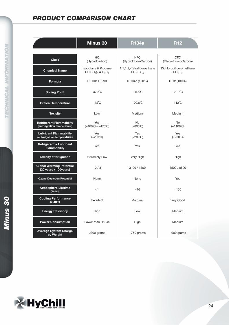
PRODUCT COMPARISON CHART
Minus 30 R134a R12
ClassHC
(HydroCarbon)HFC
(HydroFluoroCarbon)CFC
(ChloroFluoroCarbon)
Chemical NameIsobutane & Propane
CH(CH3)3 & C3H8
1,1,1,2,-Tetrafluoroethane CH2FCF3
Dichlorodifluoromethane CCI2F2
Formula R-600a R-290 R-134a (100%) R-12 (100%)
Boiling Point -37.8˚C -26.6˚C -29.7˚C
Critical Temperature 112˚C 100.6˚C 112˚C
Toxicity Low Medium Medium
Refrigerant Flammability (auto-ignition temperature)
Yes (~460˚C - ~470˚C)
No (~800˚C)
No (~1100˚C)
Lubricant Flammability (auto-ignition temperature)
Yes (~200˚C)
Yes (~200˚C)
Yes (~200˚C)
Refrigerant + Lubricant Flammability Yes Yes Yes
Toxicity after ignition Extremely Low Very High High
Global Warming Potential (20 years / 100years) ~0 / 3 3100 / 1300 8500 / 8500
Ozone Depletion Potential None None Yes
Atmosphere Lifetime (Years) <1 ~16 ~130
Cooling Performance @ 40˚C Excellent Marginal Very Good
Energy Efficiency High Low Medium
Power Consumption Lower than R134a High Medium
Average System Charge by Weight <300 grams ~750 grams ~900 grams


![Past, present and future perspectives of refrigerants in air … · 2014. 4. 16. · synthesised by two effects [ 7]: − depletion of the ozone layer; − contribution to global](https://img.pdfslide.us/doc/110x75/60e07f11c0eeb75b1723d149/past-present-and-future-perspectives-of-refrigerants-in-air-2014-4-16-synthesised.jpg)