Embed Size (px)
Citation preview
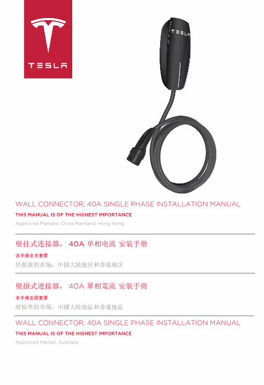
WALL CONNECTOR, 40A SINGLE PHASE INSTALLATION MANUALTHIS MANUAL IS OF THE HIGHEST IMPORTANCE
Approved Markets: China Mainland, Hong Kong
壁挂式连接器, 40A 单相电流 安装手册
该手册至关重要
经批准的市场:中国大陆地区和香港地区
壁掛式連接器, 40A 單相電流 安裝手冊
本手冊至關重要
經核準的市場:中國大陸地區和香港地區
WALL CONNECTOR, 40A SINGLE PHASE INSTALLATION MANUALTHIS MANUAL IS OF THE HIGHEST IMPORTANCE
Approved Market: Australia
Cover_Tri_Language_Covers_and_Dividers.fm Page 1 Tuesday, July 15, 2014 1:41 PM

Cover_Tri_Language_Covers_and_Dividers.fm Page 2 Tuesday, July 15, 2014 1:41 PM

WALL CONNECTOR, 40A SINGLE PHASE INSTALLATION MANUAL
China, Hong Kong
Cover_Tri_Language_Covers_and_Dividers.fm Page 3 Tuesday, July 15, 2014 1:41 PM
©2014 TESLA MOTORS, INC. All rights reserved. All information in this document and all MODEL S® software is subject to copyright and other intellectual property rights of Tesla Motors, Inc. and its licensors. This material may not be modified, reproduced or copied, in whole or in part, without the prior written permission of Tesla Motors, Inc. and its licensors. Additional information is available upon request. The following are trademarks or registered trademarks of Tesla Motors, Inc. in the United States and other countries:
All other trademarks contained in this document are the property of their respective owners and their use herein does not imply sponsorship or endorsement of their products or services. The unauthorized use of any trademark displayed in this document or on the vehicle is strictly prohibited.
TESLA TESLA MOTORS TESLAROADSTER
MODEL S MODEL X
PRODUCT SPECIFICATIONS
All specifications and descriptions contained in this document are verified to be accurate at the time of printing. However, because continuous improvement is a goal at Tesla, we reserve the right to make product modifications at any time.
ERRORS OR OMISSIONS
To communicate any inaccuracies or omissions in this manual, please send an email to:[email protected].
Cover_Tri_Language_Covers_and_Dividers.fm Page 4 Tuesday, July 15, 2014 1:41 PM
CHINA MAINLAND, HONG KONG i
TABLE OF CONTENTS
IMPORTANT ! READ THIS ENTIRE MANDATORY DOCUMENT BEFORE INSTALLING OR USING THE WALL CONNECTOR. FAILURE TO DO SO OR TO FOLLOW ANY OF THE INSTRUCTIONS AND WARNINGS IN THIS DOCUMENT CAN RESULT IN FIRE, ELECTRICAL SHOCK, SERIOUS INJURY OR DEATH.
THE WALL CONNECTOR MUST BE INSTALLED BY A DULY REGISTERED AND QUALIFIED ELECTRICIAN, AND IN ACCORDANCE WITH LOCAL REGULATIONS AND ORDINANCES GOVERNING ELECTRICAL APPLIANCES AND THEIR INSTALLATION, USE, AND MAINTENANCE.
Safety Information .................................................................................................................................................. 1
Specifications...........................................................................................................................................................2
Features .....................................................................................................................................................................3
Service Wiring - Single Phase............................................................................................................................4
Installation Overview ............................................................................................................................................5
Step One - Check Box Contents ......................................................................................................................6
Step Two - Install Wall Bracket ........................................................................................................................7
Step Three - Prepare for Installation ..............................................................................................................8
Step Four - Mount on Wall .................................................................................................................................9
Step Five - Connect Wiring.............................................................................................................................. 10
Step Six - Set the Operating Current ............................................................................................................ 11
Step Seven - Confirm a Successful Installation ........................................................................................ 12
Step Eight - Secure Cover and Power Up .................................................................................................. 13
Step Nine - Install the Cable Hanger............................................................................................................. 14
Troubleshooting.................................................................................................................................................... 15
Maintenance and Repair .................................................................................................................................... 16
Wall_Connector_Install_Guide_China_1039343-00-B.book Page i Thursday, July 17, 2014 10:56 AM

1
Wall_Connector_Install_Guide_China_1039343-00-B.book Page 1 Thursday, July 17, 2014 10:56 AM
Safety Information
SAVE THESE IMPORTANT SAFETY INSTRUCTIONS
This document contains important instructions and warnings that must be followed when installing and maintaining the Wall Connector.
WARNINGS
The Wall Connector must be grounded through a permanent wiring system or an equipment grounding conductor. Do not install or use the Wall Connector near flammable, explosive, harsh, or combustible materials, chemicals, or vapors.Turn off input power at the circuit breaker before installing or cleaning the Wall Connector.Use the Wall Connector only within the specified operating parameters. The Wall Connector is designed only for charging a Tesla vehicle (excluding Tesla Roadster). Do not use it for any other purpose or with any other vehicle or object.Never spray water or any other liquid directly at the wall mounted control box. Never spray any liquid onto the charge handle or submerge the charge handle in liquid. Store the charge handle above the ground to prevent unnecessary exposure to contamination or moisture.Stop using and do not use the Wall Connector if it is defective, appears cracked, frayed, broken, or otherwise damaged, or fails to operate, or continue operation.Do not attempt to disassemble, repair, tamper with, or modify the Wall Connector. The Wall Connector is not user serviceable. Contact Tesla for any repairs or modification.When transporting the Wall Connector, handle with care. Do not subject it to strong force or impact or pull, twist, tangle, drag, or step on the Wall Connector, to prevent damage to it or any components.Do not touch the Wall Connector’s end terminals with sharp metallic objects, such as wire, tools, or needles.Do not forcefully fold or apply pressure to any part of the Wall Connector or damage it with sharp objects.Do not insert foreign objects into any part of the Wall Connector.Do not use the Wall Connector when a vehicle cover is on the vehicle. Use of the Wall Connector may affect or impair the operation of any medical or implantable electronic devices, such as an implantable cardiac pacemaker or an implantable cardioverter defibrillator. Check with your electronic device manufacturer concerning the effects that charging may have on such electronic devices before using the Wall Connector.
CAUTIONS
Incorrect installation and testing of the Wall Connector could potentially damage either the vehicle’s Battery and/or the Wall Connector itself. Any resulting damage is excluded from New Vehicle Limited Warranty and the Wall Connector Limited Warranty.Do not operate the Wall Connector in temperatures outside its operating range of -30°C to +45°C.Ensure that the Wall Connector’s charging cable is positioned so it will not be stepped on, driven over, tripped on, or subjected to damage or stress.Do not use cleaning solvents to clean any of the Wall Connector’s components. The outside of the Wall Connector, the charging cable, and the connector end of the charging cable should be periodically wiped with a clean dry cloth to remove accumulation of dirt and dust.Be careful not to damage the circuit board when removing the power entry knock-out.
WALL CONNECTOR INSTALLATION GUIDE
Wall_Connector_Install_Guide_China_1039343-00-B.book Page 2 Thursday, July 17, 2014 10:56 AM
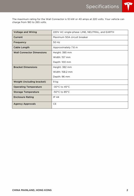
Specifications
The maximum rating for the Wall Connector is 10 kW or 40 amps at 220 volts. Your vehicle can charge from 180 to 265 volts.
Voltage and Wiring 220V AC single-phase: LINE, NEUTRAL, and EARTH
Current Maximum 50A circuit breaker
Frequency 50 Hz
Cable Length Approximately 7.6 m
Wall Connector Dimensions Height: 385 mm
Width: 157 mm
Depth: 100 mm
Bracket Dimensions Height: 382 mm
Width: 158.2 mm
Depth: 96 mm
Weight (including bracket) 9 kg
Operating Temperature -30°C to 45°C
Storage Temperature -50°C to 85°C
Enclosure Rating IP 44
Agency Approvals CE
CHINA MAINLAND, HONG KONG 2
3
Wall_Connector_Install_Guide_China_1039343-00-B.book Page 3 Thursday, July 17, 2014 10:56 AM
Features
OPTIONAL CIRCUIT RATINGS
For the fastest charging, using a circuit breaker rated for 50 amps is recommended.
SELF-MONITORING AND RECOVERY
The Wall Connector has a ground monitoring circuit that continuously checks for the presence of a safe ground connection and automatically recovers from faults. Manual testing and resetting is not required.
Temporary problems such as ground faults or utility power surges are overcome automatically. If a GFCI fault occurs that interrupts charging, the Wall Connector automatically tries to clear the fault and re-attempt charging.
If the problem is immediately sensed a second time, the Wall Connector waits 15 minutes before trying to charge. This process repeats eight times and if all attempts are unsuccessful, power is removed and no further attempts are made. In this case, a red error light lights up on the front panel (refer to the troubleshooting table on page 15). It is recommended that when you see a red error light, you power off the Wall Connector by switching off the circuit breaker, and then power it back on again.
POWER OUTAGES
If a power outage occurs, the Wall Connector automatically resumes charging when power is restored. If the charging cable is plugged into the vehicle when power is restored, the lights blink and the unit does not energize the charging cable for approximately 15 seconds to 3 minutes. This prevents the utility grid from experiencing a large surge when power is restored, allowing vehicles to begin drawing current at random times, rather than all at once.
WALL CONNECTOR INSTALLATION GUIDE
Wall_Connector_Install_Guide_China_1039343-00-B.book Page 4 Thursday, July 17, 2014 10:56 AM
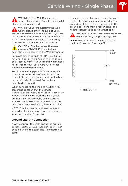
Service Wiring - Single Phase
WARNING: The Wall Connector is a single-phase device. Do not connect all 3
phases of a 3-phase feed.
WARNING: Before installing the Wall Connector, identify the type of utility
service connection available on site. If you are unsure about the type of connection available at the service panel, consult the local utility company, or contact Tesla for assistance.
CAUTION: The line connection must measure 220V RMS to neutral. earth
must also be connected to the Wall Connector.
For most branch circuits of 50A, use 16 mm2, 75°C hard copper wire. Ground wiring should be at least 10 mm2. If your ground wiring does not fit into the bus, use a wire nut or other suitable connection method.
Run 32 mm metal pipe and flame retardant conduit on the left side of a wall stud. The conduit fits into the opening on either the back or the left side of the Wall Connector as described on page 8.
When connecting the line and neutral wires, care must be taken that the service transformer secondary connection is definitely known, and the wires from the main circuit breaker panel are correctly connected and labeled. The illustrations provided show the most commonly used wiring format in China.
NOTE: The line, neutral, and earth outputs labeled on the illustrations correspond to the inputs on the Wall Connector.
Ground (Earth) ConnectionAlways connect the earth line at the service panel to earth. Ground fault protection is not possible unless the earth line is connected to earth.
If an earth connection is not available, you must install a grounding stake nearby. The grounding stake must be connected to the ground bar in the main breaker panel, and neutral connected to earth at that point.
WARNING: Follow local electrical codes when installing the grounding stake.
IMPORTANT! Dip switch 4 must be set to the 1 (left) position. See page 11.
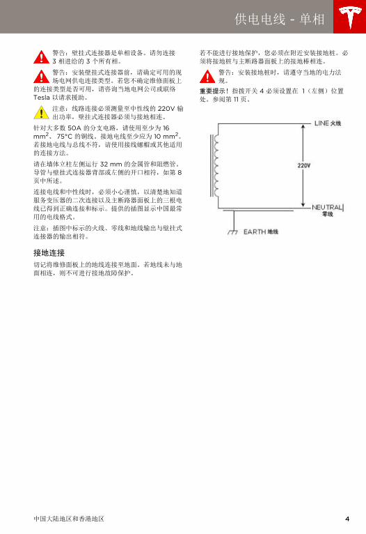
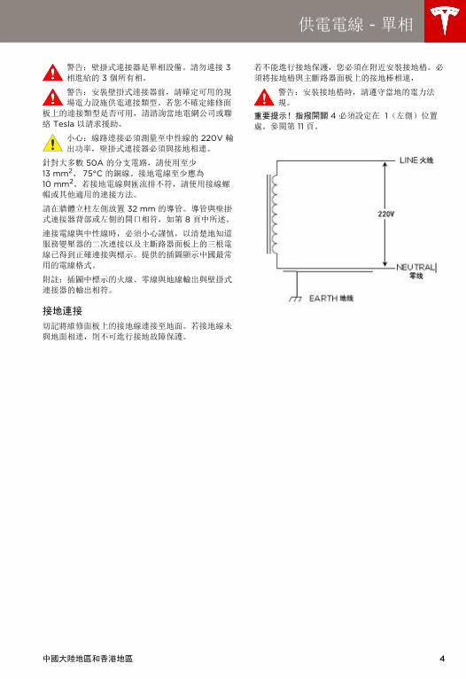
NEUTRAL
LINE
EARTH
220V
CHINA MAINLAND, HONG KONG 4
5
Wall_Connector_Install_Guide_China_1039343-00-B.book Page 5 Thursday, July 17, 2014 10:56 AM
Installation Overview
TOOLS REQUIRED
Before installing the Wall Connector, ensure you have the following tools:
• Pencil or marker
• Drill and 8 mm drill bit
• T20 torx driver
• Hole saw, 32 mm
• Sharp knife or razor
• Phillips screwdriver
• Wire stripper
• Ratchet wrench with 8 mm and 17 mm sockets, and a 50 mm minimum extension
• Voltmeter or digital multimeter (to measure AC power at the site)
OVERVIEW OF STEPS
After running service wiring to the desired installation location using 32 mm metal pipe and flame retardant conduit, (see pages 4 through 4), and installing the appropriate circuit breaker, TURN OFF THE POWER SUPPLY. Then follow these steps to install the Wall Connector:
1 Check box contents (see page 6)
2 Install wall bracket (see page 7)
3 Prepare for installation (see page 8)
4 Mount on wall (see page 9)
5 Connect wiring (see page 10)
6 Set the operating current (see page 11)
7 Confirm a successful installation (see page 12)
8 Secure cover and power up (see page 13)
9 Install the cable hanger (see page 14)
WALL CONNECTOR INSTALLATION GUIDE
Wall_Connector_Install_Guide_China_1039343-00-B.book Page 6 Thursday, July 17, 2014 10:56 AM
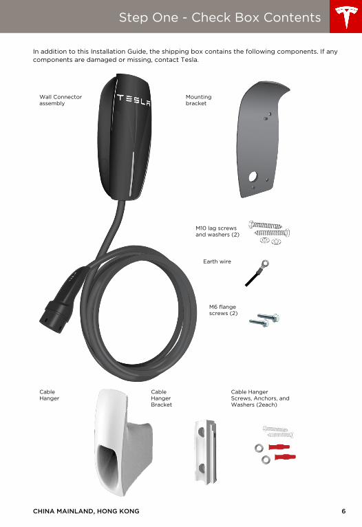
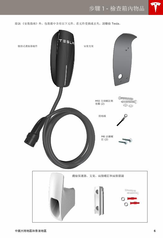
Step One - Check Box Contents
In addition to this Installation Guide, the shipping box contains the following components. If any components are damaged or missing, contact Tesla.
Wall Connector assembly
Mounting bracket
M10 lag screws and washers (2)
Earth wire
M6 flange screws (2)
CableHanger
CableHangerBracket
Cable HangerScrews, Anchors, and Washers (2each)
CHINA MAINLAND, HONG KONG 6
7
Wall_Connector_Install_Guide_China_1039343-00-B.book Page 7 Thursday, July 17, 2014 10:56 AM
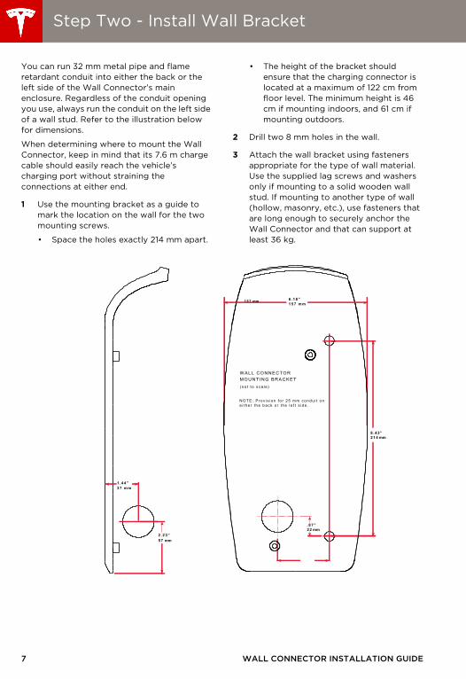
Step Two - Install Wall Bracket
You can run 32 mm metal pipe and flame retardant conduit into either the back or the left side of the Wall Connector’s main enclosure. Regardless of the conduit opening you use, always run the conduit on the left side of a wall stud. Refer to the illustration below for dimensions.
When determining where to mount the Wall Connector, keep in mind that its 7.6 m charge cable should easily reach the vehicle’s charging port without straining the connections at either end.
1 Use the mounting bracket as a guide to mark the location on the wall for the two mounting screws.
• Space the holes exactly 214 mm apart.
• The height of the bracket should ensure that the charging connector is located at a maximum of 122 cm from floor level. The minimum height is 46 cm if mounting indoors, and 61 cm if mounting outdoors.
2 Drill two 8 mm holes in the wall.
3 Attach the wall bracket using fasteners appropriate for the type of wall material. Use the supplied lag screws and washers only if mounting to a solid wooden wall stud. If mounting to another type of wall (hollow, masonry, etc.), use fasteners that are long enough to securely anchor the Wall Connector and that can support at least 36 kg.
8 .43”214 mm
.87”22 mm
6.18”
W A L L CONNE CT ORM OUNT I NG B RA CK E T(no t t o sca l e )
NOTE: P rov i s i on f o r 25 mm condu i t one i t he r t he back o r t he l e f t s i de .
157 mm
37 m m1.44”
57 mm2.23”
157 mm
WALL CONNECTOR INSTALLATION GUIDE
Wall_Connector_Install_Guide_China_1039343-00-B.book Page 8 Thursday, July 17, 2014 10:56 AM
Step Three - Prepare for Installation
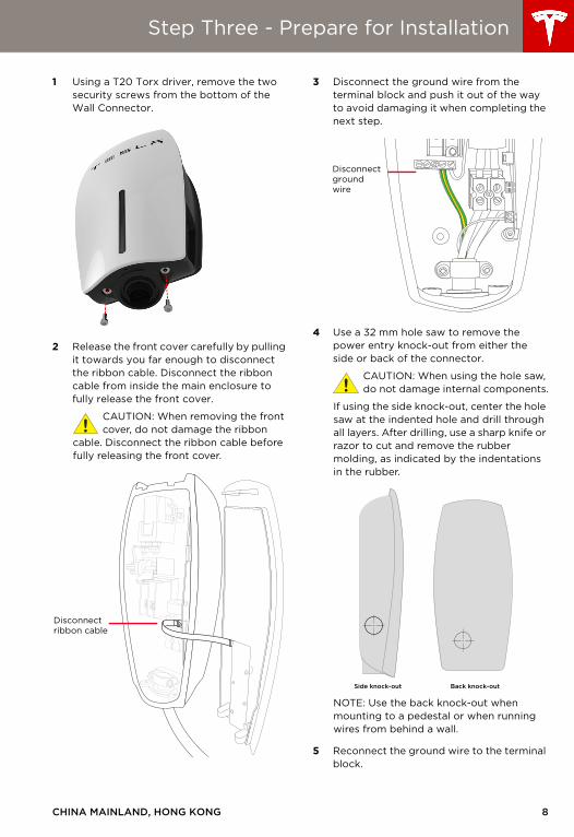
1 Using a T20 Torx driver, remove the two security screws from the bottom of the Wall Connector.
2 Release the front cover carefully by pulling it towards you far enough to disconnect the ribbon cable. Disconnect the ribbon cable from inside the main enclosure to fully release the front cover.
CAUTION: When removing the front cover, do not damage the ribbon
cable. Disconnect the ribbon cable before fully releasing the front cover.
3 Disconnect the ground wire from the terminal block and push it out of the way to avoid damaging it when completing the next step.
4 Use a 32 mm hole saw to remove the power entry knock-out from either the side or back of the connector.
CAUTION: When using the hole saw, do not damage internal components.
If using the side knock-out, center the hole saw at the indented hole and drill through all layers. After drilling, use a sharp knife or razor to cut and remove the rubber molding, as indicated by the indentations in the rubber.
NOTE: Use the back knock-out when mounting to a pedestal or when running wires from behind a wall.
5 Reconnect the ground wire to the terminal block.
Disconnectribbon cable
Disconnectgroundwire
Side knock-out Back knock-out
CHINA MAINLAND, HONG KONG 8

9
Wall_Connector_Install_Guide_China_1039343-00-B.book Page 9 Thursday, July 17, 2014 10:56 AM
Step Four - Mount on Wall
1 Position the connector over the bolts on the mounting bracket as shown below.
2 Attach the ground wire, as shown below.
3 Use the supplied flange screws to fasten the connector onto the bracket. Use a ratchet wrench and 8 mm socket to tighten until snugly fitted.
WALL CONNECTOR INSTALLATION GUIDE
Wall_Connector_Install_Guide_China_1039343-00-B.book Page 10 Thursday, July 17, 2014 10:56 AM
Step Five - Connect Wiring
NOTE: For most branch circuits of 50A, use 16 mm2, 75°C hard copper wire.
WARNING: Do not connect service wiring until you have read and fully
understand page 4 in this document describing the service wiring. If you are uncertain about the type of power available at the service panel, consult your local utility, or contact Tesla for assistance.
1 Turn off the power.
WARNING: RISK OF ELECTRIC SHOCK! Before connecting the
wiring, use a voltmeter to confirm that NO POWER is available at the service wiring or terminals.
2 Pull the service wiring into the Wall Connector. If using a hub, connect conduit to the hub before connecting it to the enclosure.
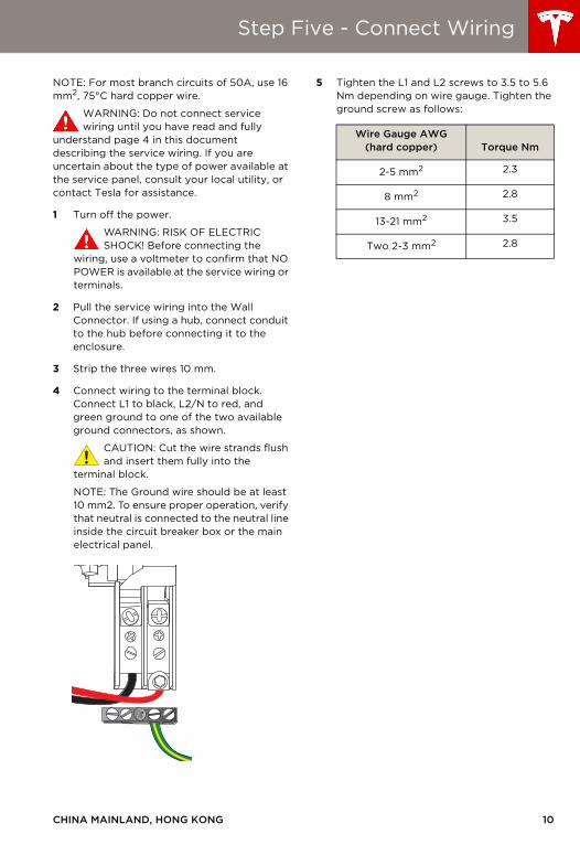
3 Strip the three wires 10 mm.
4 Connect wiring to the terminal block. Connect L1 to black, L2/N to red, and green ground to one of the two available ground connectors, as shown.
CAUTION: Cut the wire strands flush and insert them fully into the
terminal block.
NOTE: The Ground wire should be at least 10 mm2. To ensure proper operation, verify that neutral is connected to the neutral line inside the circuit breaker box or the main electrical panel.
5 Tighten the L1 and L2 screws to 3.5 to 5.6 Nm depending on wire gauge. Tighten the ground screw as follows:
Wire Gauge AWG(hard copper) Torque Nm
2-5 mm2 2.3
8 mm2 2.8
13-21 mm2 3.5
Two 2-3 mm2 2.8
CHINA MAINLAND, HONG KONG 10
11
Wall_Connector_Install_Guide_China_1039343-00-B.book Page 11 Thursday, July 17, 2014 10:56 AM
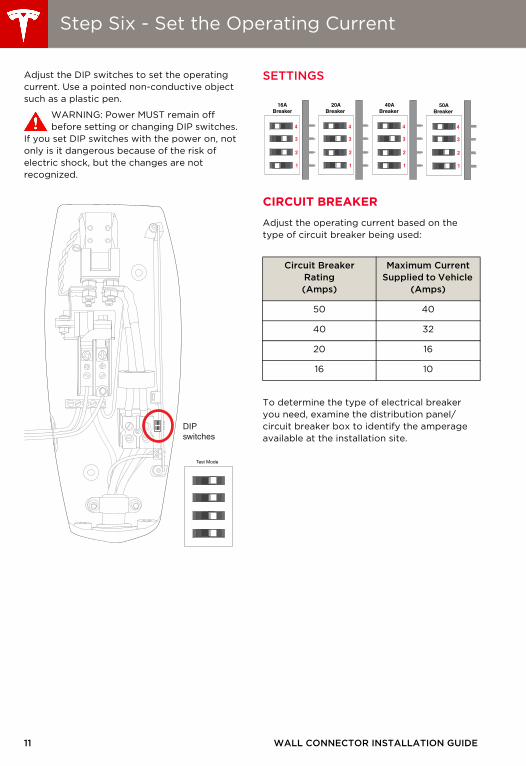
Step Six - Set the Operating Current
Adjust the DIP switches to set the operating current. Use a pointed non-conductive object such as a plastic pen.
WARNING: Power MUST remain off before setting or changing DIP switches.
If you set DIP switches with the power on, not only is it dangerous because of the risk of electric shock, but the changes are not recognized.
SETTINGS
CIRCUIT BREAKER
Adjust the operating current based on the type of circuit breaker being used:
To determine the type of electrical breaker you need, examine the distribution panel/circuit breaker box to identify the amperage available at the installation site.
DIPswitches
Test Mode
Circuit Breaker Rating(Amps)
Maximum Current Supplied to Vehicle
(Amps)
50 40
40 32
20 16
16 10
1
2
3
4
1
2
3
4
1
2
3
4
1
2
3
4
16ABreaker
20ABreaker
40ABreaker
50ABreaker
WALL CONNECTOR INSTALLATION GUIDE
Wall_Connector_Install_Guide_China_1039343-00-B.book Page 12 Thursday, July 17, 2014 10:56 AM
Step Seven - Confirm a Successful Installation
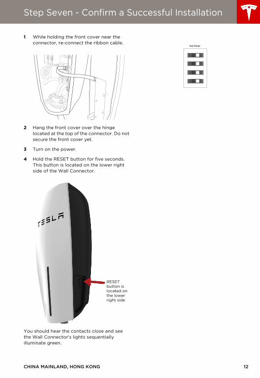
1 While holding the front cover near the connector, re-connect the ribbon cable.
2 Hang the front cover over the hinge located at the top of the connector. Do not secure the front cover yet.
3 Turn on the power.
4 Hold the RESET button for five seconds. This button is located on the lower right side of the Wall Connector.
You should hear the contacts close and see the Wall Connector’s lights sequentially illuminate green.
RESET button is located on the lower right side
Test Mode
CHINA MAINLAND, HONG KONG 12
13 WALL CONNECTOR INSTALLATION GUIDE
Step Eight - Secure Cover and Power Up
1 Reposition the front cover over the unit, aligning the five tabs on the back of the front cover with their corresponding slots. Starting at the bottom and working upwards, press firmly on both sides of the front cover until it clicks into place.
2 Using a T20 torx driver, re-attach the two security screws that you removed from the bottom of the Wall Connector in “Step Three - Prepare for Installation” on page 8.
3 Turn on the power.
4 Attempt to charge the car to ensure the Wall Connector is operating correctly and charging at the selected operating current. For instructions on how to charge, refer to the owner information provided with your vehicle.
MPWCContents.fm Page 13 Friday, July 18, 2014 9:52 AM
CHINA MAINLAND, HONG KONG 14
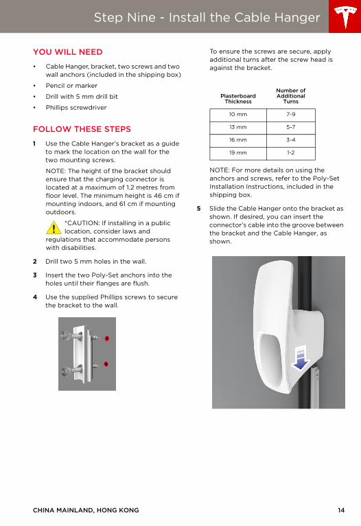
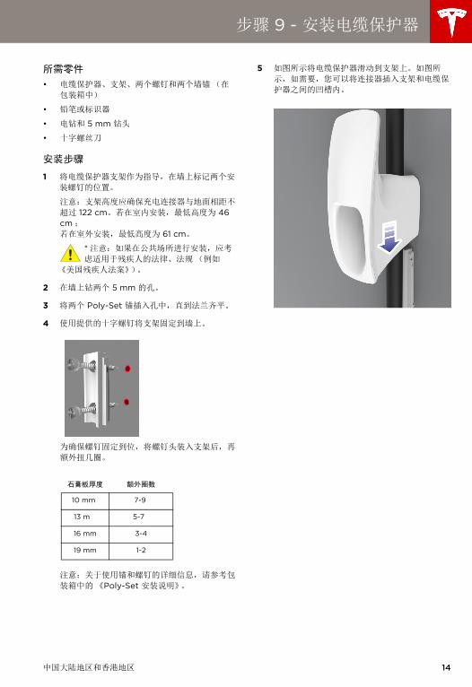
Step Nine - Install the Cable Hanger
YOU WILL NEED
• Cable Hanger, bracket, two screws and two wall anchors (included in the shipping box)
• Pencil or marker
• Drill with 5 mm drill bit
• Phillips screwdriver
FOLLOW THESE STEPS
1 Use the Cable Hanger’s bracket as a guide to mark the location on the wall for the two mounting screws.
NOTE: The height of the bracket should ensure that the charging connector is located at a maximum of 1.2 metres from floor level. The minimum height is 46 cm if mounting indoors, and 61 cm if mounting outdoors.
*CAUTION: If installing in a public location, consider laws and
regulations that accommodate persons with disabilities.
2 Drill two 5 mm holes in the wall.
3 Insert the two Poly-Set anchors into the holes until their flanges are flush.
4 Use the supplied Phillips screws to secure the bracket to the wall.
To ensure the screws are secure, apply additional turns after the screw head is against the bracket.
NOTE: For more details on using the anchors and screws, refer to the Poly-Set Installation Instructions, included in the shipping box.
5 Slide the Cable Hanger onto the bracket as shown. If desired, you can insert the connector’s cable into the groove between the bracket and the Cable Hanger, as shown.
PlasterboardThickness
Number of Additional
Turns
10 mm 7-9
13 mm 5-7
16 mm 3-4
19 mm 1-2
MPWCContents.fm Page 14 Friday, July 18, 2014 9:52 AM

15
Wall_Connector_Install_Guide_China_1039343-00-B.book Page 15 Thursday, July 17, 2014 10:56 AM
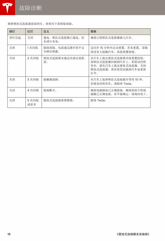
Troubleshooting
Observe the lights on the front of the Wall Connector, then use the following table to resolve a fault.
Green Lights
Red Light What It Means What To Do
Top light on
Off Power on. Wall Connector is powered, but not charging.
Make sure the Wall Connector is plugged into the car.
Off 1 flash Ground fault. Electrical current is leaking through a potentially unsafe path.
This should automatically reset in 15 minutes. If not, make sure nobody is touching the car, then press the RESET button.
Off 2 flashes The Wall Connector did not pass its internal self check.
Unplug the Wall Connector from the car and press the RESET button. Plug the Wall Connector back into the car. If the error persists, unplug the Wall Connector from the car, power off the Wall Connector, then power it back on again before plugging it back into the car.
Off 3 flashes Contactor failed. Unplug the Wall Connector from the car and wait 10 seconds. If the error persists, contact Tesla.
Off 4 flashes Ground lost. Make sure the power outlet is properly grounded. Make sure the hot and neutral pins are wired properly. If uncertain, ask your electrician.
Off 5 flashes or more
The Wall Connector requires servicing.
Contact Tesla.
WALL CONNECTOR INSTALLATION GUIDE
Wall_Connector_Install_Guide_China_1039343-00-B.book Page 16 Thursday, July 17, 2014 10:56 AM
Maintenance and Repair
Always ensure that after charging, the charging cable is wrapped around the Wall Connector.
Regularly inspect the Wall Connector and charging cable for signs of damage. If damage is found, contact Tesla.
The Wall Connector contains no user-serviceable components. If the unit is not operating correctly, contact Tesla.
Wipe the outside of the Wall Connector, the charging cable, and the connector end of the charging cable with a clean dry cloth to remove any accumulation of dust and dirt.
WARNING: Turn off input power at the circuit breaker before cleaning the Wall
Connector.
WARNING: Do not use cleaning solvents, scouring powder, or any type of abrasive
pad to clean the Wall Connector, its charging cable, or the vehicle’s charging port.
CAUTION: To reduce the risk of electrical shock or equipment damage,
do not allow liquid to enter the Wall Connector while cleaning it.
CHINA MAINLAND, HONG KONG 16

Wall_Connector_Install_Guide_China_1039343-00-B.book Page 17 Thursday, July 17, 2014 10:56 AM

壁挂式连接器, 40A 单相电流
安装手册
中国大陆地区和香港地区
Cover_Tri_Language_Covers_and_Dividers.fm Page 5 Tuesday, July 15, 2014 1:41 PM
©2014 特斯拉电机公司保留所有权利。 本文档中的所有信息以及所有 MODEL S® 软件的版权和其他知识产权归特斯拉电机公司及其授权人所有。未经特斯拉电机公司及其授权人事先书面许可,不得对资料进行全部或部分复印、复制或修改。可根据要求提供其他信息。以下是特斯拉电机公司在美国和其他国家(地区)的商标或注册商标:
本文档所包含的所有其他的商标是其各自所有者的财产;本文使用这些商标,并不意味对其产品或服务的赞助或背书认可。严禁擅用本文档中显示的或汽车上的任何商标。
TESLA 特斯拉电机 特斯拉跑车 MODEL S MODEL X
产品规格
此文件中的所有规格和说明均已在打印时得到验证,以确保准确无误。但是,因为持续改善是 Tesla 的目标,我们保留随时进行修改的权利。
错误或疏漏
若要传达此手册中的不准确或疏漏之处,请发送电子邮件至:[email protected]。
Cover_Tri_Language_Covers_and_Dividers.fm Page 6 Tuesday, July 15, 2014 1:41 PM
中国大陆地区和香港地区 i
目录
重要提示! 安装或使用壁挂式连接器前,请通读此必备文件。若未阅读或未遵守此文件中的说明和警告,则会导致火灾、
触电、严重伤害或死亡。
壁挂式连接器必须由正式注册的合格电工进行安装,并遵守管理电器及其安装、使用和维护的地方法规和条例。
安全信息........................................................................................................................................................................ 1
规格...............................................................................................................................................................................2
特性...............................................................................................................................................................................3
供电电线 - 单相 ..........................................................................................................................................................4
安装简介.......................................................................................................................................................................5
步骤 1 - 检查箱内物品 ...............................................................................................................................................6
步骤 2 - 安装壁挂支架 ..............................................................................................................................................7
步骤 3 - 准备安装.......................................................................................................................................................8
步骤 4 - 安装到墙上 ..................................................................................................................................................9
步骤 5 - 连接电线..................................................................................................................................................... 10
步骤 6 - 设置工作电流 ............................................................................................................................................. 11
步骤 7 - 确认是否正确安装 .................................................................................................................................... 12
步骤 8 - 固定罩子并通电 ........................................................................................................................................ 13
步骤 9 - 安装电缆保护器 ........................................................................................................................................ 14
故障诊断..................................................................................................................................................................... 15
维护和维修................................................................................................................................................................. 16
Wall_Connector_Install_Guide_China_S-CH.book Page i Thursday, July 17, 2014 11:09 AM
1
Wall_Connector_Install_Guide_China_S-CH.book Page 1 Thursday, July 17, 2014 11:09 AM
安全信息
保存此类重要的安全说明
该文件包含安装和维护壁挂式连接器时需要遵守的重要说明和警告。
警告
该壁挂式连接器必须通过永久电线系统或设备接地导体进行接地。 请勿在易燃、易爆、粗糙或可燃材料、化学物或蒸汽附近安装或使用壁挂式连接器。
安装或清洁壁挂式连接器前,请关闭断路器上的输入电源。
仅按照指定的操作参数使用壁挂式连接器。 设计该壁挂式连接器仅供特斯拉车辆(不包括特斯拉跑车)充电。请勿将其用于其他目的或其他车辆或物体。
请勿将水或其他液体直接喷到安装在墙上的控制箱上。请勿将水喷到充电把手上或将充电把手浸在液体中。将充电把手存放在地面上方,以防止接触不必要的污染物或水汽。
若壁挂式连接器存在缺陷、出现裂痕、磨损、破裂或受到损坏或不能作业或持续运行,则请停止使用或不要使用。
请勿试图拆卸、维修、摆弄或改装壁挂式连接器。壁挂式连接器不是用户可维修的设备。若要进行任何维修或改装,请联络 Tesla。运输壁挂式连接器时,请务必小心谨慎。请勿使其承受强作用力或冲击力或拉动、扭曲、缠结、拖拽或踩踏壁挂式连接器,以防止其自身或组件受损。
请勿用锋利的金属物体(例如电线、工具或针)接触壁挂式连接器的末端。
请勿将壁挂式连接器的任何部件用力折叠或对其施加压力或使用锋利的物体进行破坏。
请勿将异物插入壁挂式连接器的任何部件。
若车罩在车辆上,则请勿使用壁挂式连接器。 使用壁挂式连接器会影响或损坏医疗或植入式电子设备的操作,例如植入式心脏起搏器或植入式心电复律去纤颤器。使用壁挂式连接器前,请就充电对此类电子设备的影响向电子设备制造商进行咨询。
注意
壁挂式连接器的错误安装和测试会对车辆电池和 / 或壁挂式连接器本身带来潜在的损坏。导致的任何损坏均不属于《新车有限质量保证》和《壁挂式连接器有限质量保证》的保修范围。
请勿在超出壁挂式连接器操作范围 (-30°C - +45°C) 的温度下操作壁挂式连接器。
确保已将壁挂式连接器的充电电缆妥善放置,因此其不会被踩踏、被压入、被绊住或受到损坏或压力。
请勿使用清洁剂清洁壁挂式连接器的任何组件。应定期使用干净的干布擦拭壁挂式连接器的外部、充电电缆和连接器末端,以清除积聚的脏污和灰尘。
拆卸接电缺口时,请勿破坏电路板。
《壁挂式连接器安装指南》
Wall_Connector_Install_Guide_China_S-CH.book Page 2 Thursday, July 17, 2014 11:09 AM
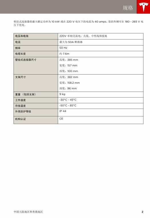
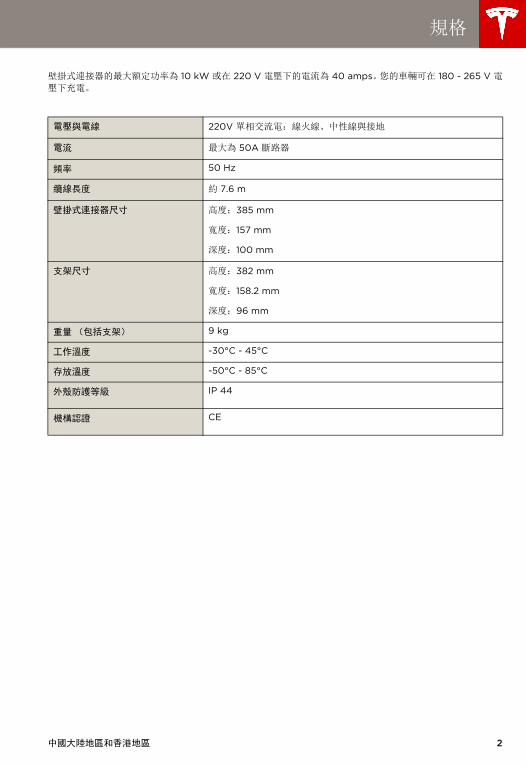
规格
壁挂式连接器的最大额定功率为 10 kW 或在 220 V 电压下的电流为 40 amps。您的车辆可在 180 - 265 V 电压下充电。
电压和电线 220V 单相交流电:火线、中性线和接地
电流 最大为 50A 断路器
频率 50 Hz
电缆长度 约 7.6m
壁挂式连接器尺寸 高度:385 mm
宽度:157 mm
深度:100 mm
支架尺寸 高度:382 mm
宽度:158.2 mm
深度:96 mm
重量 (包括支架) 9 kg
工作温度 -30°C - 45°C
存放温度 -50°C - 85°C
外壳防护等级 IP 44
机构认证 CE
中国大陆地区和香港地区 2
3
Wall_Connector_Install_Guide_China_S-CH.book Page 3 Thursday, July 17, 2014 11:09 AM
特性
可选电路等级
为快速充电,建议使用额定电流为 50 amps 的断路
器。
自我监控和恢复
壁挂式连接器设有接地监控电路,其持续检查是否进
行安全的接地连接并自动从故障中恢复。不要求手动
测试和重新设置。
接地故障或电网功率骤增等临时问题均可自动解决。
若出现影响充电的接地故障断路器故障,则壁挂式连
接器会自动尝试消除故障并重新试图充电。
若再次立即感应到该问题,则壁挂式连接器在尝试充
电前会等待 15 分钟。将该流程重复八次,若所有尝
试均失败,则会断电且不再进行其他尝试。在此情况
下,前面板上的红色错误指示灯将会亮起 (参阅第 15 页中的故障诊断表)。建议在您看到红色错误指示
灯时,可通过关闭断路器来关闭壁挂式连接器,然后
将其再次打开。
电力中断
若出现电力中断的情况,则壁挂式连接器会在电力恢
复后自动恢复充电。若在电力恢复后将充电电缆插入
车辆,则灯会闪烁且装置在约 15 秒至 3 分钟内不会
激活充电电缆。这避免公共电网在电力恢复后出现功
率骤增的情况,以随机的方式 (而非突然)让车辆
开始充电。
《壁挂式连接器安装指南》
Wall_Connector_Install_Guide_China_S-CH.book Page 4 Thursday, July 17, 2014 11:09 AM
供电电线 - 单相
警告:壁挂式连接器是单相设备。请勿连接 3 相进给的 3 个所有相。
警告:安装壁挂式连接器前,请确定可用的现
场电网供电连接类型。若您不确定维修面板上
的连接类型是否可用,请咨询当地电网公司或联络 Tesla 以请求援助。
注意:线路连接必须测量至中性线的 220V 输出功率,壁挂式连接器必须与接地相连。
针对大多数 50A 的分支电路,请使用至少为 16 mm2、 75°C 的铜线。接地电线至少应为 10 mm2。
若接地电线与总线不符,请使用接线螺帽或其他适用
的连接方法。
请在墙体立柱左侧运行 32 mm 的金属管和阻燃管。
导管与壁挂式连接器背部或左侧的开口相符,如第 8 页中所述。
连接电线和中性线时,必须小心谨慎,以清楚地知道
服务变压器的二次连接以及主断路器面板上的三根电
线已得到正确连接和标示。提供的插图显示中国最常
用的电线格式。
注意:插图中标示的火线、零线和地线输出与壁挂式
连接器的输出相符。
接地连接
切记将维修面板上的地线连接至地面。若地线未与地
面相连,则不可进行接地故障保护。
若不能进行接地保护,您必须在附近安装接地桩。必
须将接地桩与主断路器面板上的接地棒相连。
警告:安装接地桩时,请遵守当地的电力法
规。
重要提示!指拨开关 4 必须设置在 1(左侧)位置
处。参阅第 11 页。
中国大陆地区和香港地区 4
5
Wall_Connector_Install_Guide_China_S-CH.book Page 5 Thursday, July 17, 2014 11:09 AM
安装简介
所需工具
安装壁挂式连接器前,请确保拥有以下工具:
• 铅笔或标识器
• 电钻和 8 mm 钻头
• T20 梅花起子
• 32 mm 的孔锯
• 尖刀或剃刀
• 十字螺丝刀
• 剥线器
• 带 8 mm 和 17 mm 套筒且延伸长度至少为 50mm 的棘轮扳手
• 伏特计或数字万用表 (用于测量现场的交流电
源)
步骤简介
使用 32 mm 金属管和阻燃管将供电电线送到所需安
装位置 (参阅第 4 页至第 4 页)并安装正确的断路
器后,请关闭电源。之后,按照以下步骤安装壁挂式
连接器:
1 检查箱内物品 (参阅第 6 页)。
2 安装壁挂支架 (参阅第 7 页)。
3 准备安装 (参阅第 8 页)。
4 安装到墙上(参阅第 9 页)
5 连接电线 (参阅第 10 页)
6 设置工作电流 (参阅第 11 页)
7 确认是否正确安装 (参阅第 12 页)
8 固定罩子并通电 (参阅第 13 页)
9 安装电缆保护器 (参阅第 14 页)
《壁挂式连接器安装指南》
Wall_Connector_Install_Guide_China_S-CH.book Page 6 Thursday, July 17, 2014 11:09 AM
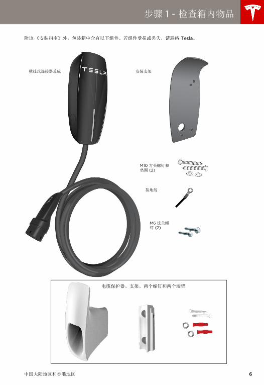
步骤 1 - 检查箱内物品
除该《安装指南》外,包装箱中含有以下组件。若组件受损或丢失,请联络 Tesla。
壁挂式连接器总成 安装支架
M10 方头螺钉和垫圈 (2)
接地线
M6 法兰螺钉 (2)
电缆保护器、支架、两个螺钉和两个墙锚
中国大陆地区和香港地区 6
7
Wall_Connector_Install_Guide_China_S-CH.book Page 7 Thursday, July 17, 2014 11:09 AM
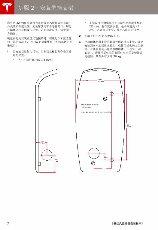
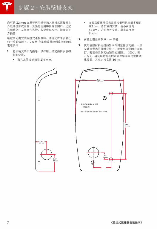
步骤 2 - 安装壁挂支架
您可将 32 mm 金属管和阻燃管插入壁挂式连接器主
外壳的后部或左侧。无论您使用哪个导管开口,切记
在墙体立柱左侧操作导管。若要获取尺寸,请参阅下
方插图。
确定在何处安装壁挂式连接器时,请谨记在未张紧任
何一端的情况下, 7.6 m 充电电缆易于到达车辆的充
电端口。
1 将安装支架作为指导,以在墙上标记两个安装螺
钉的位置。
• 使孔之间恰好相隔 214 mm。
• 支架高度应确保充电连接器与地面最多相距 122 cm。若在室内安装,最小高度为 46 cm ;若在室外安装,最小高度为 61 cm。
2 在墙上钻出两个 8 mm 的孔。
3 使用墙体材料支持的紧固件固定壁挂支架。只要
安装到实木的墙体立柱上,就使用提供的方头螺
钉。若要安装到其他类型的墙体上 (空心、砌
石等),请使用足够长的紧固件牢牢固定壁挂式
连接器,其至少可支撑 36 kg。
8 .43”214 mm
.87”22 mm
6.18”
25 mm
1 5 7 mm
37 mm1.44”
57 mm2.23”
157 mm
《壁挂式连接器安装指南》

Wall_Connector_Install_Guide_China_S-CH.book Page 8 Thursday, July 17, 2014 11:09 AM
步骤 3 - 准备安装
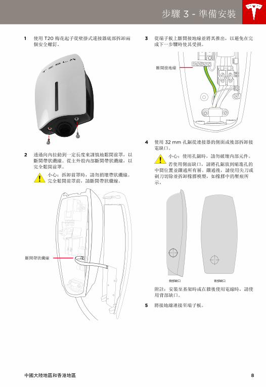
1 使用 T20 梅花起子从壁挂式连接器底部拆卸两
个安全螺钉。
2 通过向内拉动到一定长度来谨慎地松开前罩,以
断开带状电缆。从主外壳内部断开带状电缆,以
完全松开前罩。
注意:拆卸前罩时,请勿损坏带状电缆。
完全松开前罩前,请断开带状电缆。
3 从端子板上断开接地线并将其推出,以避免在完
成下一步骤时使其受损。
4 使用 32 mm 孔锯从连接器的侧面或后部拆卸接
电缺口。
注意:使用孔锯时,请勿破坏内部组件。
若使用侧面缺口,请将孔锯放到缩进孔的
中间位置并钻通所有层。钻通后,请使用尖刀或
剃刀切除并拆卸橡胶模塑,如橡胶中的压痕所
示。
注意:安装至基架时或在墙后使用电线时,请使
用背部缺口。
5 将接地线连接至端子板。
断开带状电缆
断开接地线
中国大陆地区和香港地区 8
9
Wall_Connector_Install_Guide_China_S-CH.book Page 9 Thursday, July 17, 2014 11:09 AM
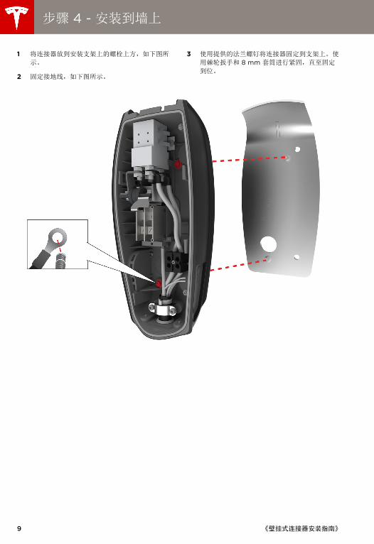
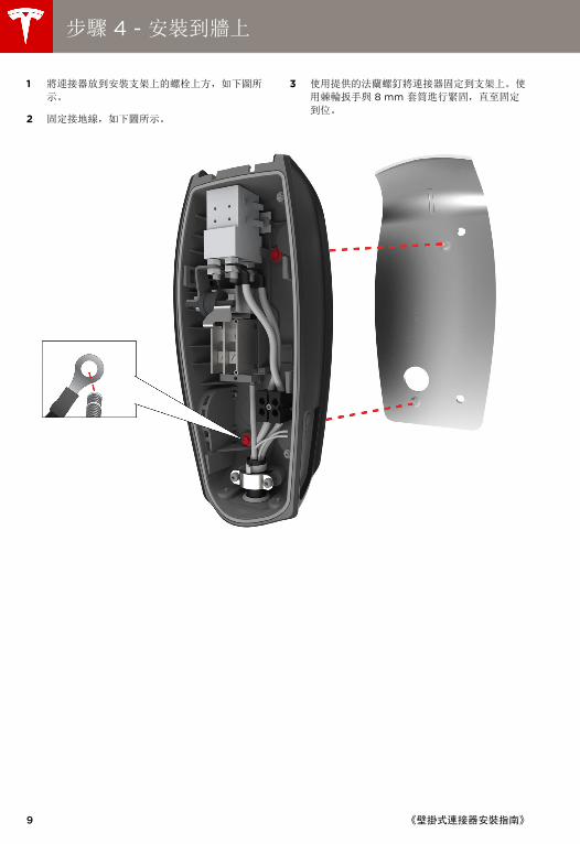
步骤 4 - 安装到墙上
1 将连接器放到安装支架上的螺栓上方,如下图所
示。
2 固定接地线,如下图所示。
3 使用提供的法兰螺钉将连接器固定到支架上。使
用棘轮扳手和 8 mm 套筒进行紧固,直至固定
到位。
《壁挂式连接器安装指南》
Wall_Connector_Install_Guide_China_S-CH.book Page 10 Thursday, July 17, 2014 11:09 AM
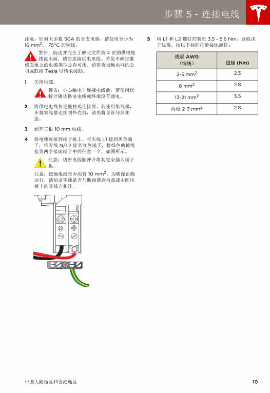
步骤 5 - 连接电线
注意:针对大多数 50A 的分支电路,请使用至少为 16 mm2、 75°C 的铜线。
警告:阅读并完全了解此文件第 4 页的供电电
线说明前,请勿连接供电电线。若您不确定维
修面板上的电源类型是否可用,请咨询当地电网的公
司或联络 Tesla 以请求援助。
1 关闭电源。
警告:小心触电!连接电线前,请使用伏
特计确认供电电线或终端没有通电。
2 将供电电线拉进壁挂式连接器。若使用集线器,
在将集线器连接到外壳前,请先将导管与其相
连。
3 剥开三根 10 mm 电线。
4 将电线连接到端子板上。将火线 L1 接到黑色端
子,将零线 N/L2 接到红色端子,将绿色的地线
接到两个接地端子中的任意一个,如图所示。
注意:切断电线脉冲并将其完全插入端子
板。
注意:接地电线至少应有 10 mm2。为确保正确
运行,请验证零线是否与断路器盒内部或主配电
板上的零线点相连。
5 将 L1 和 L2 螺钉拧紧至 3.5 - 5.6 Nm,这取决
于线规。按以下标准拧紧接地螺钉:
线规 AWG(铜线) 扭矩 (Nm)
2-5 mm2 2.3
8 mm2 2.8
13-21 mm2 3.5
两根 2-3 mm2 2.8
中国大陆地区和香港地区 10
11
Wall_Connector_Install_Guide_China_S-CH.book Page 11 Thursday, July 17, 2014 11:09 AM
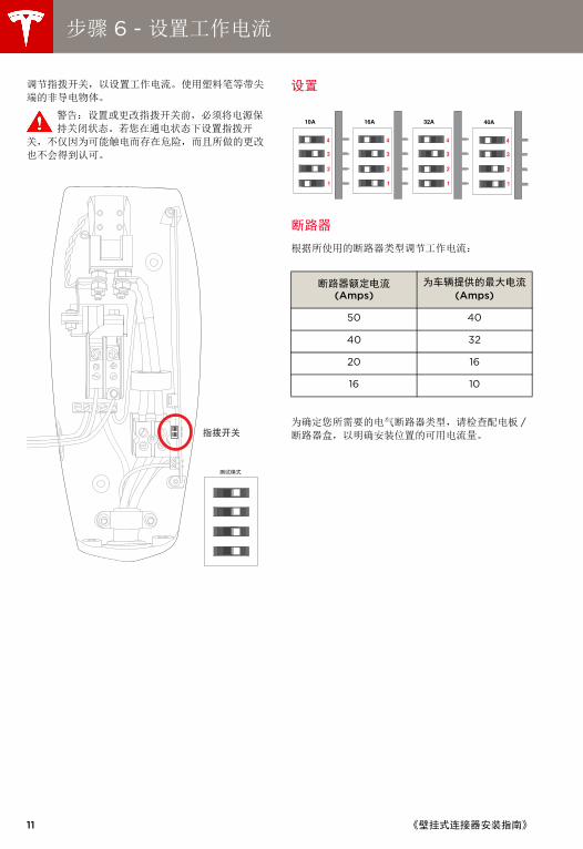
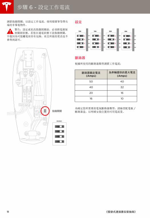
步骤 6 - 设置工作电流
调节指拨开关,以设置工作电流。使用塑料笔等带尖
端的非导电物体。
警告:设置或更改指拨开关前,必须将电源保
持关闭状态。若您在通电状态下设置指拨开
关,不仅因为可能触电而存在危险,而且所做的更改
也不会得到认可。
设置
断路器
根据所使用的断路器类型调节工作电流:
为确定您所需要的电气断路器类型,请检查配电板 /断路器盒,以明确安装位置的可用电流量。
断路器额定电流(Amps)
为车辆提供的最大电流 (Amps)
50 40
40 32
20 16
16 10
10A 16A 32A
1
2
3
4
1
2
3
4
1
2
3
4
40A
1
2
3
4
《壁挂式连接器安装指南》
Wall_Connector_Install_Guide_China_S-CH.book Page 12 Thursday, July 17, 2014 11:09 AM
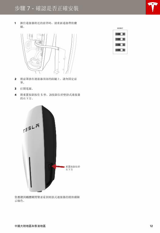
步骤 7 - 确认是否正确安装
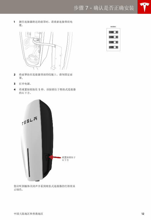
1 握住连接器附近的前罩时,请重新连接带状电
缆。
2 将前罩挂在连接器顶部的铰链上。请勿固定前
罩。
3 打开电源。
4 将重置按钮按住 5 秒。该按钮位于壁挂式连接器
的右下方。
您应听到触体关闭声并看到壁挂式连接器的灯持续显
示绿色。
重置按钮位于右下方
中国大陆地区和香港地区 12
13
Wall_Connector_Install_Guide_China_S-CH.book Page 13 Thursday, July 17, 2014 11:09 AM
步骤 8 - 固定罩子并通电
1 将前罩重新放到装置上方,将前罩背部的五个锁
片与相应的插槽对齐。从底部开始并向上操作,
紧紧按住前罩两侧,直至其完全嵌入。
2 使用 T20 梅花起子,重新接上您在第 8 页的“步骤 3 - 准备安装 ” 中从壁挂式连接器的底部拆卸
的安全螺钉。
3 打开电源。
4 尝试为您的电动车充电,以确保壁挂式连接器正
确运行并按照选定的工作电流进行充电。有关如
何充电的说明,请参阅与车辆一同提供的车主信
息。
《壁挂式连接器安装指南》
Wall_Connector_Install_Guide_China_S-CH.book Page 14 Thursday, July 17, 2014 11:09 AM
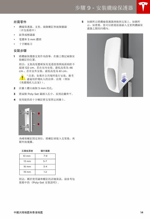
步骤 9 - 安装电缆保护器
所需零件
• 电缆保护器、支架、两个螺钉和两个墙锚(在
包装箱中)
• 铅笔或标识器
• 电钻和 5 mm 钻头
• 十字螺丝刀
安装步骤
1 将电缆保护器支架作为指导,在墙上标记两个安
装螺钉的位置。
注意:支架高度应确保充电连接器与地面相距不
超过 122 cm。若在室内安装,最低高度为 46 cm ;
若在室外安装,最低高度为 61 cm。
* 注意:如果在公共场所进行安装,应考
虑适用于残疾人的法律、法规 (例如
《美国残疾人法案》)。
2 在墙上钻两个 5 mm 的孔。
3 将两个 Poly-Set 锚插入孔中,直到法兰齐平。
4 使用提供的十字螺钉将支架固定到墙上。
为确保螺钉固定到位,将螺钉头装入支架后,再
额外扭几圈。
注意:关于使用锚和螺钉的详细信息,请参考包
装箱中的 《Poly-Set 安装说明》。
5 如图所示将电缆保护器滑动到支架上。如图所
示,如需要,您可以将连接器插入支架和电缆保
护器之间的凹槽内。
石膏板厚度 额外圈数
10 mm 7-9
13 m 5-7
16 mm 3-4
19 mm 1-2
中国大陆地区和香港地区 14
15
Wall_Connector_Install_Guide_China_S-CH.book Page 15 Thursday, July 17, 2014 11:09 AM
故障诊断
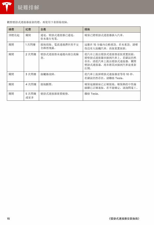
观察壁挂式连接器前部的灯,再使用下表排除故障。
绿灯 红灯 含义 措施
顶灯亮起 关闭 通电。壁挂式连接器已通电,但
未进行充电。
确保已将壁挂式连接器插入汽车。
关闭 1 次闪烁 接地故障。电流通过潜在的不安
全路径泄露。
这应在 15 分钟内自动重置。若未重置,请确
保没有人接触汽车,再按重置按钮。
关闭 2 次闪烁 壁挂式连接器未通过内部自我检
查。
从汽车上拔出壁挂式连接器并按重置按钮。
将壁挂式连接器回插到汽车上。若错误仍然
存在,请从汽车上拔出壁挂式连接器,关闭
壁挂式连接器,再在将其回插到汽车前重新
打开。
关闭 3 次闪烁 接触器故障。 从汽车上拔掉壁挂式连接器并等待 10 秒。
若错误仍然存在,请联络 Tesla。
关闭 4 次闪烁 接地断开。 确保电源插座已正确接地。确保热的中性线
插脚已正确连接。若不能确定,请询问电工。
关闭 5 次闪烁
或更多
壁挂式连接器需要维修。 联络 Tesla。
《壁挂式连接器安装指南》
Wall_Connector_Install_Guide_China_S-CH.book Page 16 Thursday, July 17, 2014 11:09 AM
维护和维修
务必确保在充电后,将充电电缆缠绕在壁挂式连接器
上。
定期检查壁挂式连接器和充电电缆有无损坏。若发现
损坏,请联络 Tesla。
壁挂式连接器不包含用户可维修的组件。若装置未正
常运行,请联络 Tesla。
用干净的干布擦拭壁挂式连接器外部、充电电缆和充
电电缆的连接器末端,以清除积聚的脏污和灰尘。
警告:清洁壁挂式连接器前,请关闭断路器的
输入电源。
警告:请勿使用清洁剂、去污粉或任何研磨垫清
洁壁挂式连接器、其充电电缆或车辆充电端口。
注意:为降低触电或设备故障风险,在清洁
时,不得让液体进入壁挂式连接器。
中国大陆地区和香港地区 16

Wall_Connector_Install_Guide_China_S-CH.book Page 17 Thursday, July 17, 2014 11:09 AM

壁掛式連接器, 40A 單相電流
安裝手冊
中國大陸地區和香港地區
Cover_Tri_Language_Covers_and_Dividers.fm Page 7 Tuesday, July 15, 2014 1:41 PM
©2014 TESLA MOTORS, INC. 保留所有權利。 本文件及所有 MODEL S® 軟體中的所有資訊均受 Tesla Motors, Inc. 及其授權人之著作權及其他智慧財產權法的保護。若事先未獲得 Tesla Motors, Inc. 及其授權人的書面許可,則不得對資料中的全部或部分內容進行修改、重現或複製。可根據要求提供其他資訊。以下為 Tesla Motors, Inc. 在美國及其他國家 / 地區的商標或註冊商標:
本文件中包含的所有其他商標均為各擁有者之財產,本文對其的使用並不表示贊助或認可其產品或服務。嚴禁在未經授權的情況下使用本文件或車輛上顯示的任何商標。
TESLA 特斯拉電機 特斯拉跑車 MODEL S MODEL X
產品規格
本文件中所含之所有規格與說明已於列印之時驗證,均準確無誤。但是,因 Tesla 致力於不斷改進,我們保留隨時修改產品之權利。
錯誤或遺漏
若要針對本手冊中的任何不准確或遺漏之處進行交流,請將電子郵件傳送至:[email protected].
Cover_Tri_Language_Covers_and_Dividers.fm Page 8 Tuesday, July 15, 2014 1:41 PM
中國大陸地區和香港地區 i
目錄
重要提示! 安裝或使用壁掛式連接器前,請通讀此必備文件。若未閱讀或未遵守此文件中的說明與警告,則會導致火災、觸
電、嚴重傷害或死亡。
該壁掛式連接器必須由正式註冊的合格電工進行安裝,並遵守管理電器及其安裝、使用與維護的地方法規與條例。
安全資訊........................................................................................................................................................................ 1
規格...............................................................................................................................................................................2
功能...............................................................................................................................................................................3
供電電線 - 單相 ..........................................................................................................................................................4
安裝概觀.......................................................................................................................................................................5
步驟 1 - 檢查箱內物品 ...............................................................................................................................................6
步驟 2 - 安裝壁掛支架 ..............................................................................................................................................7
步驟 3 - 準備安裝.......................................................................................................................................................8
步驟 4 - 安裝到牆上 ..................................................................................................................................................9
步驟 5 - 連接電線..................................................................................................................................................... 10
步驟 6 - 設定工作電流 ............................................................................................................................................. 11
步驟 7 - 確認是否正確安裝 .................................................................................................................................... 12
步驟 8 - 固定罩子並通電 ........................................................................................................................................ 13
步驟 9 - 安裝纜線保護器 ................................................................................................................................................. 14
疑難排解..................................................................................................................................................................... 15
維護與維修................................................................................................................................................................. 16
Wall_Connector_Install_Guide_China.book Page i Thursday, July 17, 2014 11:23 AM

1
Wall_Connector_Install_Guide_China.book Page 1 Thursday, July 17, 2014 11:23 AM
安全資訊
保存此類重要的安全說明
此文件包含安裝與維護壁掛式連接器時需要遵守的重要說明與警告。
警告
該壁掛式連接器必須透過永久電線系統或設備接地導體進行接地。 請勿在易燃、易爆、粗糙或可燃材料、化學物或蒸汽附近安裝或使用壁掛式連接器。
安裝或清潔壁掛式連接器前,請關閉斷路器上的輸入電源。
僅按照指定的指令引數使用壁掛式連接器。 設計該壁掛式連接器僅供特斯拉車輛(不包括 Tesla Roadster)充電。請勿將其用於其他目的或其他車輛或物件。
請勿將水或其他液體直接噴到安裝在牆上的控制箱上。請勿將水噴到充電把手上或將充電把手浸在液體中。將充電把手存放在地面上方,以防止接觸不必要的污染物或水汽。
若壁掛式連接器存在缺陷、出現裂痕、磨損、破裂或受到損壞或不能作業或持續運行,則請停止使用或不要使用。
請勿試圖拆卸、維修、擺弄或改裝壁掛式連接器。壁掛式連接器不是使用者可維修的設備。若要進行任何維修或改裝,請聯絡 Tesla。運輸壁掛式連接器時,請務必小心謹慎。請勿使其承受強作用力或衝擊力或拉動、扭曲、纏結、拖拽或踩踏壁掛式連接器,以防止其自身或元件受損。
請勿用鋒利的金屬物件(例如電線、工具或針)接觸壁掛式連接器的末端。
請勿將壁掛式連接器的任何部件用力折疊或對其施加壓力或使用鋒利的物件進行破壞。
請勿將異物插入壁掛式連接器的任何部件。
若車罩在車輛上,則請勿使用壁掛式連接器。 使用壁掛式連接器會影響或損壞醫療或植入式電子設備的操作,例如植入式心臟起搏器或植入式心電複律去纖顫器。使用壁掛式連接器前,請就充電對此類電子設備的影響向電子設備製造商進行諮詢。
小心
壁掛式連接器的錯誤安裝與測試會對車輛電池與 / 或壁掛式連接器本身帶來潛在的損壞。導致的任何損壞均不屬於《新車有限品質保證》與《壁掛式連接器有限品質保證》之保修範圍。
請勿在超出壁掛式連接器操作範圍 (-30°C - +45°C) 的溫度下操作壁掛式連接器。
確保已將壁掛式連接器的充電纜線妥善放置,因此其不會被踩踏、被壓入、被絆住或受到損壞或壓力。 1請勿使用清潔劑清潔壁掛式連接器的任何元件。應定期使用乾淨的幹布擦拭壁掛式連接器的外部、充電纜線與連接器末端,以清除積聚的髒汙與灰塵。
拆卸接電缺口時,請勿破壞電路板。
《壁掛式連接器安裝指南》
Wall_Connector_Install_Guide_China.book Page 2 Thursday, July 17, 2014 11:23 AM
規格
壁掛式連接器的最大額定功率為 10 kW 或在 220 V 電壓下的電流為 40 amps。您的車輛可在 180 - 265 V 電壓下充電。
電壓與電線 220V 單相交流電:線火線、中性線與接地
電流 最大為 50A 斷路器
頻率 50 Hz
纜線長度 約 7.6 m
壁掛式連接器尺寸 高度:385 mm
寬度:157 mm
深度:100 mm
支架尺寸 高度:382 mm
寬度:158.2 mm
深度:96 mm
重量 (包括支架) 9 kg
工作溫度 -30°C - 45°C
存放溫度 -50°C - 85°C
外殼防護等級 IP 44
機構認證 CE
中國大陸地區和香港地區 2

3
Wall_Connector_Install_Guide_China.book Page 3 Thursday, July 17, 2014 11:23 AM
功能
可選電路等級
為快速充電,建議使用額定電流為 50 amps 的斷路
器。
自我監控與恢復
壁掛式連接器設有接地監控電路,其持續檢查是否進
行安全的接地連接並自動從故障中恢復。不要求手動
測試與重新設定。
接地故障或電網功率驟增等臨時問題均可自動解決。
若出現影響充電的接地故障斷路器故障,則壁掛式連
接器會自動嘗試消除故障並重新試圖充電。
若再次立即感應到該問題,則壁掛式連接器在嘗試充
電前會等待 15 分鐘。將該流程重複八次,若所有嘗
試均失敗,則會斷電且不再進行其他嘗試。在此情況
下,前面板上的紅色錯誤指示燈將會亮起 (參閱第 15 頁中的疑難排解表)。建議在您看到紅色錯誤指示
燈時,可透過關閉斷路器來關閉壁掛式連接器,然後
將其再次打開。
電力中斷
若出現電力中斷的情況,則壁掛式連接器會在電力恢
復後自動恢復充電。若在電力恢復後將充電纜線插入
車輛,則燈會閃爍且裝置在約 15 秒至 3 分鐘內不會
啟動充電纜線。這避免公共電網在電力恢復後出現功
率驟增的情況,以隨機的方式 (而非突然)讓車輛
開始充電。
《壁掛式連接器安裝指南》
Wall_Connector_Install_Guide_China.book Page 4 Thursday, July 17, 2014 11:23 AM
供電電線 - 單相
警告:壁掛式連接器是單相設備。請勿連接 3 相進給的 3 個所有相。
警告:安裝壁掛式連接器前,請確定可用的現
場電力設施供電連接類型。若您不確定維修面
板上的連接類型是否可用,請諮詢當地電網公司或聯
絡 Tesla 以請求援助。
小心:線路連接必須測量至中性線的 220V 輸出功率,壁掛式連接器必須與接地相連。
針對大多數 50A 的分支電路,請使用至少 13 mm2、 75°C 的銅線。接地電線至少應為 10 mm2。若接地電線與匯流排不符,請使用接線螺
帽或其他適用的連接方法。
請在牆體立柱左側放置 32 mm 的導管。導管與壁掛
式連接器背部或左側的開口相符,如第 8 頁中所述。
連接電線與中性線時,必須小心謹慎,以清楚地知道
服務變壓器的二次連接以及主斷路器面板上的三根電
線已得到正確連接與標示。提供的插圖顯示中國最常
用的電線格式。
附註:插圖中標示的火線、零線與地線輸出與壁掛式
連接器的輸出相符。
接地連接
切記將維修面板上的接地線連接至地面。若接地線未
與地面相連,則不可進行接地故障保護。
若不能進行接地保護,您必須在附近安裝接地樁。必
須將接地樁與主斷路器面板上的接地棒相連,
警告:安裝接地樁時,請遵守當地的電力法
規。
重要提示!指撥開關 4 必須設定在 1(左側)位置
處。參閱第 11 頁。
中國大陸地區和香港地區 4

5
Wall_Connector_Install_Guide_China.book Page 5 Thursday, July 17, 2014 11:23 AM
安裝概觀
所需工具
安裝壁掛式連接器前,請確保擁有以下工具:
• 鉛筆或標識器
• 電鑽與 8 mm 鑽頭
• T20 梅花起子
• 32 mm 孔鋸
• 尖刀或剃刀
• 十字螺絲刀
• 剝線器
• 帶 8 mm 與 17 mm 套筒且延伸長度至少為 50 mm 的棘輪扳手
• 電壓計或數位萬用表 (用於測量現場的交流電
源)
步驟概觀
使用 32 mm 金屬管與阻燃管將供電電線送到所需安
裝位置 (參閱第 4 頁至第 4 頁)並安裝正確的斷路
器之後,請關閉電源。之後,按照以下步驟安裝壁掛
式連接器:
1 檢查箱內物品 (參閱第 6 頁)。
2 安裝壁掛支架 (參閱第 7 頁)。
3 準備安裝 (參閱第 8 頁)。
4 安裝到牆上(參閱第 9 頁)
5 連接電線 (參閱第 10 頁)
6 設定工作電流 (參閱第 11 頁)
7 確認是否正確安裝 (參閱第 12 頁)
8 固定罩子並通電 (參閱第 13 頁)
9 安裝纜線保護器 參閱第 14 頁)
《壁掛式連接器安裝指南》
Wall_Connector_Install_Guide_China.book Page 6 Thursday, July 17, 2014 11:23 AM
步驟 1 - 檢查箱內物品
除該《安裝指南》外,包裝箱中含有以下元件。若元件受損或丟失,請聯絡 Tesla。
壁掛式連接器組件 安裝支架
M10 方頭螺釘與墊圈 (2)
接地線
M6 法蘭螺釘 (2)
纜線保護器、支架、兩個螺釘和兩個牆錨
中國大陸地區和香港地區 6
7
Wall_Connector_Install_Guide_China.book Page 7 Thursday, July 17, 2014 11:23 AM
步驟 2 - 安裝壁掛支架
您可將 32 mm 金屬管與阻燃管插入壁掛式連接器主
外殼的後部或左側。無論您使用哪個導管開口,切記
在牆體立柱左側操作導管。若要獲取尺寸,請參閱下
方插圖。
確定在何處安裝壁掛式連接器時,請謹記在未張緊任
何一端的情況下, 7.6 m 充電纜線易於到達車輛的充
電連接埠。
1 將安裝支架作為指導,以在牆上標記兩個安裝螺
釘的位置。
• 將孔之間恰好相隔 214 mm。
• 支架高度應確保充電連接器與地面最多相距 122 cm。若在室內安裝,最小高度為 46 cm ;若在室外安裝,最小高度為 61 cm。
2 在牆上鑽出兩個 8 mm 的孔。
3 使用牆體材料支援的緊固件固定壁掛支架。一旦
安裝到實木的牆體立柱上,就使用提供的方頭螺
釘。若要安裝到其他類型的牆體上 (空心、砌
石等),請使用足夠長的緊固件牢牢固定壁掛式
連接器,其至少可支撐 36 kg。
8 .43”214 mm
.87”22 mm
6.18”
壁掛式連接器安裝支架(不按比例)
附註:請在背部或左側使用 25 mm 導管。
157 mm
37 m m1.44”
57 mm2.23”
157 mm
《壁掛式連接器安裝指南》
Wall_Connector_Install_Guide_China.book Page 8 Thursday, July 17, 2014 11:23 AM
步驟 3 - 準備安裝
1 使用 T20 梅花起子從壁掛式連接器底部拆卸兩
個安全螺釘。
2 透過向內拉動到一定長度來謹慎地鬆開前罩,以
斷開帶狀纜線。從主外殼內部斷開帶狀纜線,以
完全鬆開前罩。
小心:拆卸前罩時,請勿損壞帶狀纜線。
完全鬆開前罩前,請斷開帶狀纜線。
3 從端子板上斷開接地線並將其推出,以避免在完
成下一步驟時使其受損。
4 使用 32 mm 孔鋸從連接器的側面或後部拆卸接
電缺口。
小心:使用孔鋸時,請勿破壞內部元件。
若使用側面缺口,請將孔鋸放到縮進孔的
中間位置並鑽通所有層。鑽通後,請使用尖刀或
剃刀切除並拆卸橡膠模塑,如橡膠中的壓痕所
示。
附註:安裝至基架時或在牆後使用電線時,請使
用背部缺口。
5 將接地線連接至端子板。
斷開帶狀纜線
斷開接地線
側部缺口 背部缺口
中國大陸地區和香港地區 8
9
Wall_Connector_Install_Guide_China.book Page 9 Thursday, July 17, 2014 11:23 AM
步驟 4 - 安裝到牆上
1 將連接器放到安裝支架上的螺栓上方,如下圖所
示。
2 固定接地線,如下圖所示。
3 使用提供的法蘭螺釘將連接器固定到支架上。使
用棘輪扳手與 8 mm 套筒進行緊固,直至固定
到位。
《壁掛式連接器安裝指南》

Wall_Connector_Install_Guide_China.book Page 10 Thursday, July 17, 2014 11:23 AM
步驟 5 - 連接電線
附註:針對大多數 50A 的分支電路,請使用 16 mm2、 75°C 的銅線。
警告:閱讀並完全瞭解第 4 頁的供電電線說明
前,請勿連接供電電線。若您不確定維修面板
上的電源類型是否可用,請諮詢當地電網的公司或聯
絡 Tesla 以請求援助。
1 關閉電源。
警告:小心觸電!連接電線前,請使用電
壓計確認供電電線或終端沒有通電。
2 將供電電線拉進壁掛式連接器。若使用集線器,
在將集線器連接到外殼前,請先將導管與其相
連。
3 剝開三根 10 mm 電線。
4 將電線連接到端子板上。將火線 L1 接到黑色端
子,將零線 N/L2 接到紅色端子,將綠色的地線
接到兩個接地端子中的任意一個,如圖所示。
小心:切斷電線脈衝並將其完全插入端子
板。
附註:接地電線至少應為 10 mm2。为确保正确
运行,请验证零线是否与断路器盒内部或主配电
板上的零线点相连。
5 將 L1 與 L2 螺釘擰緊至 3.5 - 5.6 Nm,這取決
於線規。按以下標準擰緊接地螺釘:
線規 AWG(銅線) 扭矩 (Nm)
2-5 mm2 2.3
8 mm2 2.8
13-21 mm2 3.5
兩根 2-3 mm2 2.8
中國大陸地區和香港地區 10
11
Wall_Connector_Install_Guide_China.book Page 11 Thursday, July 17, 2014 11:23 AM
步驟 6 - 設定工作電流
調節指撥開關,以設定工作電流。使用塑膠筆等帶尖
端的非導電物件。
警告:設定或更改指撥開關前,必須將電源保
持關閉狀態。若您在通電狀態下設指撥開關,
不僅因為可能觸電而存在危險,而且所做的更改也不
會得到認可。
設定
斷路器
根據所使用的斷路器類型調節工作電流:
為確定您所需要的電氣斷路器類型,請檢查配電板 /斷路器盒,以明確安裝位置的可用電流量。指撥開關
測試模式
斷路器額定電流(Amps)
為車輛提供的最大電流 (Amps)
50 40
40 32
20 16
16 10
10A 16A 32A
1
2
3
4
1
2
3
4
1
2
3
4
40A
1
2
3
4
《壁掛式連接器安裝指南》
Wall_Connector_Install_Guide_China.book Page 12 Thursday, July 17, 2014 11:23 AM
步驟 7 - 確認是否正確安裝
1 握住連接器附近的前罩時,請重新連接帶狀纜
線。
2 將前罩掛在連接器頂部的鉸鏈上。請勿固定前
罩。
3 打開電源。
4 將重置按鈕按住 5 秒。該按鈕位於壁掛式連接器
的右下方。
您應聽到觸體關閉聲並看到壁掛式連接器的燈持續顯
示綠色。
重置按鈕位於右下方
測試模式
中國大陸地區和香港地區 12

13
Wall_Connector_Install_Guide_China.book Page 13 Thursday, July 17, 2014 11:23 AM
步驟 8 - 固定罩子並通電
1 將前罩重新放到裝置上方,將前罩背部的五個鎖
片與相應的插槽對齊。從底部開始並向上操作,
緊緊按住前罩兩側,直至其完全嵌入。
2 使用 T20 梅花起子,重新接上您在第 8 頁上的
“ 步驟 3 - 準備安裝 ” 中從壁掛式連接器的底部
拆卸的安全螺釘。
3 打開電源。
4 嘗試爲您的電動車充電,以確保壁掛式連接器正
確運行並按照選定的工作電流進行充電。有關如
何充電的說明,請參閱與車輛一同提供的車主資
訊。
《壁掛式連接器安裝指南》
Wall_Connector_Install_Guide_China.book Page 14 Thursday, July 17, 2014 11:23 AM
步驟 9 - 安裝纜線保護器
所需零件
• 纜線保護器、支架、兩個螺釘和兩個牆錨
(在包裝箱中)
• 鉛筆或標識器
• 電鑽和 5 mm 鑽頭
• 十字螺絲刀
安裝步驟
1 將纜線保護器支架作為指導,在牆上標記兩個安
裝螺釘的位置。
附註:支架高度應確保充電連接器與地面相距不
超過 122 cm。若在室內安裝,最低高度為 46 cm ;若在室外安裝,最低高度為 61 cm。
* 注意:如果在公共場所進行安裝,應考
慮適用於殘疾人的法律、法規 (例如
《美國殘疾人法案》)。
2 在牆上鑽出兩個 5 mm 的孔。
3 將兩個 Poly-Set 錨插入孔中,直到法蘭齊平。
4 使用提供的十字螺釘將支架固定到牆上。
為確保螺釘固定到位,將螺釘頭裝入支架後,再
額外扭幾圈。
附註:關於使用錨和螺釘的詳細資訊,請參考包
裝箱中的 《Poly-Set 安裝說明》。
5 如圖所示將纜線保護器滑動到支架上。如圖所
示,如需要,您可以將連接器插入支架與纜線保
護器之間的凹槽內。
石膏板厚度 額外圈數
10 mm 7-9
13 mm 5-7
16 mm 3-4
19 mm 1-2
中國大陸地區和香港地區 14
15
Wall_Connector_Install_Guide_China.book Page 15 Thursday, July 17, 2014 11:23 AM
疑難排解
觀察壁掛式連接器前部的燈,再使用下表排除故障。
綠燈 紅燈 含義 措施
頂燈亮起 關閉 通電。壁掛式連接器已通電,
但未進行充電。
確保已將壁掛式連接器插入汽車。
關閉 1 次閃爍 接地故障。電流透過潛在的不安
全路徑洩露。
這應在 15 分鐘內自動重設。若未重設,請確
保沒有人接觸汽車,再按重置按鈕。
關閉 2 次閃爍 壁掛式連接器未通過內部自我檢
查。
從汽車上拔出壁掛式連接器並按重置按鈕。
將壁掛式連接器回插到汽車上。若錯誤仍然
存在,請從汽車上拔出壁掛式連接器,關閉
壁掛式連接器,再在將其回插到汽車前重新
打開。
關閉 3 次閃爍 接觸器故障。 從汽車上拔掉壁掛式連接器並等待 10 秒。
若錯誤仍然存在,請聯絡 Tesla。
關閉 4 次閃爍 接地斷開。 確保電源插座已正確接地。確保熱的中性線
插腳已正確連接。若不能確定,請詢問電工。
關閉 5 次閃爍
或更多
壁掛式連接器需要維修。 聯絡 Tesla。
《壁掛式連接器安裝指南》
Wall_Connector_Install_Guide_China.book Page 16 Thursday, July 17, 2014 11:23 AM
維護與維修
務必確保在充電後,將充電纜線纏繞在壁掛式連接器
上。
定期檢查壁掛式連接器與充電纜線有無損壞。若發現
損壞,請聯絡 Tesla。
壁掛式連接器不包含使用者可維修的元件。若裝置未
正常運行,請聯絡 Tesla。
用乾淨的幹布擦拭壁掛式連接器外部、充電纜線與充
電纜線的連接器末端,以清除積聚的髒汙與灰塵。
警告:清潔壁掛式連接器前,請關閉斷路器的
輸入電源。
警告:請勿使用清潔劑、去污粉或任何研磨墊
清潔壁掛式連接器、其充電纜線或車輛充電連
接埠。
小心:為降低觸電或設備故障風險,在清潔
時,不得讓液體進入壁掛式連接器。
中國大陸地區和香港地區 16

Wall_Connector_Install_Guide_China.book Page 17 Thursday, July 17, 2014 11:23 AM

WALL CONNECTOR, 40A SINGLE PHASE INSTALLATION MANUAL
Australia
Cover_Tri_Language_Covers_and_Dividers.fm Page 9 Tuesday, July 15, 2014 1:41 PM

©2014 TESLA MOTORS, INC. All rights reserved. All information in this document and all MODEL S® software is subject to copyright and other intellectual property rights of Tesla Motors, Inc. and its licensors. This material may not be modified, reproduced or copied, in whole or in part, without the prior written permission of Tesla Motors, Inc. and its licensors. Additional information is available upon request. The following are trademarks or registered trademarks of Tesla Motors, Inc. in the United States and other countries:
All other trademarks contained in this document are the property of their respective owners and their use herein does not imply sponsorship or endorsement of their products or services. The unauthorized use of any trademark displayed in this document or on the vehicle is strictly prohibited.
TESLA TESLA MOTORS TESLAROADSTER
MODEL S MODEL X
PRODUCT SPECIFICATIONS
All specifications and descriptions contained in this document are verified to be accurate at the time of printing. However, because continuous improvement is a goal at Tesla, we reserve the right to make product modifications at any time.
ERRORS OR OMISSIONS
To communicate any inaccuracies or omissions in this manual, please send an email to:[email protected].
Cover_Tri_Language_Covers_and_Dividers.fm Page 10 Tuesday, July 15, 2014 1:41 PM
AUSTRALIA i
TABLE OF CONTENTS
IMPORTANT ! READ THIS ENTIRE MANDATORY DOCUMENT BEFORE INSTALLING OR USING THE WALL CONNECTOR. FAILURE TO DO SO OR TO FOLLOW ANY OF THE INSTRUCTIONS AND WARNINGS IN THIS DOCUMENT CAN RESULT IN FIRE, ELECTRICAL SHOCK, SERIOUS INJURY OR DEATH.
THE WALL CONNECTOR MUST BE INSTALLED BY A DULY REGISTERED AND QUALIFIED ELECTRICIAN, AND IN ACCORDANCE WITH LOCAL REGULATIONS AND ORDINANCES GOVERNING ELECTRICAL APPLIANCES AND THEIR INSTALLATION, USE, AND MAINTENANCE.
Safety Information .................................................................................................................................................. 1
Specifications...........................................................................................................................................................2
Features .....................................................................................................................................................................3
Service Wiring - Single Phase............................................................................................................................4
Installation Overview ............................................................................................................................................5
Step One - Check Box Contents ......................................................................................................................6
Step Two - Install Wall Bracket ........................................................................................................................7
Step Three - Prepare for Installation ..............................................................................................................8
Step Four - Mount on Wall .................................................................................................................................9
Step Five - Connect Wiring.............................................................................................................................. 10
Step Six - Set the Operating Current ............................................................................................................ 11
Step Seven - Confirm a Successful Installation ........................................................................................ 12
Step Eight - Secure Cover and Power Up .................................................................................................. 13
Step Nine - Install the Cable Hanger............................................................................................................. 14
Troubleshooting.................................................................................................................................................... 15
Maintenance and Repair .................................................................................................................................... 16
Wall_Connector_Install_Guide_Australia_Section_of_1046345-00-C.book Page i Thursday, July 17, 2014 10:47 AM
1
Wall_Connector_Install_Guide_Australia_Section_of_1046345-00-C.book Page 1 Thursday, July 17, 2014 10:47 AM
Safety Information
SAVE THESE IMPORTANT SAFETY INSTRUCTIONS
This document contains important instructions and warnings that must be followed when installing and maintaining the Wall Connector.
WARNINGS
The Wall Connector must be grounded through a permanent wiring system or an equipment grounding conductor. Do not install or use the Wall Connector near flammable, explosive, harsh, or combustible materials, chemicals, or vapors.Turn off input power at the circuit breaker before installing or cleaning the Wall Connector.Use the Wall Connector only within the specified operating parameters. The Wall Connector is designed only for charging a Tesla vehicle (excluding Tesla Roadster). Do not use it for any other purpose or with any other vehicle or object.Never spray water or any other liquid directly at the wall mounted control box. Never spray any liquid onto the charge handle or submerge the charge handle in liquid. Store the charge handle above the ground to prevent unnecessary exposure to contamination or moisture.Stop using and do not use the Wall Connector if it is defective, appears cracked, frayed, broken, or otherwise damaged, or fails to operate, or continue operation.Do not attempt to disassemble, repair, tamper with, or modify the Wall Connector. The Wall Connector is not user serviceable. Contact Tesla for any repairs or modification.When transporting the Wall Connector, handle with care. Do not subject it to strong force or impact or pull, twist, tangle, drag, or step on the Wall Connector, to prevent damage to it or any components.Do not touch the Wall Connector’s end terminals with sharp metallic objects, such as wire, tools, or needles.Do not forcefully fold or apply pressure to any part of the Wall Connector or damage it with sharp objects.Do not insert foreign objects into any part of the Wall Connector.Do not use the Wall Connector when a vehicle cover is on the vehicle. Use of the Wall Connector may affect or impair the operation of any medical or implantable electronic devices, such as an implantable cardiac pacemaker or an implantable cardioverter defibrillator. Check with your electronic device manufacturer concerning the effects that charging may have on such electronic devices before using the Wall Connector.
CAUTIONS
Incorrect installation and testing of the Wall Connector could potentially damage either the vehicle’s Battery and/or the Wall Connector itself. Any resulting damage is excluded from New Vehicle Limited Warranty and the Wall Connector Limited Warranty.Do not operate the Wall Connector in temperatures outside its operating range of -30°C to +45°C.Ensure that the Wall Connector’s charging cable is positioned so it will not be stepped on, driven over, tripped on, or subjected to damage or stress.Do not use cleaning solvents to clean any of the Wall Connector’s components. The outside of the Wall Connector, the charging cable, and the connector end of the charging cable should be periodically wiped with a clean dry cloth to remove accumulation of dirt and dust.Be careful not to damage the circuit board when removing the power entry knock-out.
WALL CONNECTOR INSTALLATION GUIDE
Wall_Connector_Install_Guide_Australia_Section_of_1046345-00-C.book Page 2 Thursday, July 17, 2014 10:47 AM
Specifications
The maximum rating for the Wall Connector is 10 kW or 40 amps at 240 volts. Your vehicle can charge from 180 to 265 volts.
Voltage and Wiring 240V AC single-phase: LINE, NEUTRAL, and EARTH
Current Maximum 50A circuit breaker
Frequency 50 -60 Hz
Cable Length Approximately 7.6 m
Wall Connector Dimensions Height: 385 mm
Width: 157 mm
Depth: 100 mm
Bracket Dimensions Height: 382 mm
Width: 158.2 mm
Depth: 96 mm
Weight (including bracket) 9 kg
Operating Temperature -30°C to 45°C
Storage Temperature -50°C to 85°C
Enclosure Rating IP 44
Agency Approvals CE
AUSTRALIA 2

3
Wall_Connector_Install_Guide_Australia_Section_of_1046345-00-C.book Page 3 Thursday, July 17, 2014 10:47 AM
Features
OPTIONAL CIRCUIT RATINGS
For the fastest charging, using a circuit breaker rated for 50 amps is recommended.
SELF-MONITORING AND RECOVERY
The Wall Connector has a ground monitoring circuit that continuously checks for the presence of a safe ground connection and automatically recovers from faults. Manual testing and resetting is not required.
Temporary problems such as ground faults or utility power surges are overcome automatically. If a GFCI fault occurs that interrupts charging, the Wall Connector automatically tries to clear the fault and re-attempt charging.
If the problem is immediately sensed a second time, the Wall Connector waits 15 minutes before trying to charge. This process repeats eight times and if all attempts are unsuccessful, power is removed and no further attempts are made. In this case, a red error light lights up on the front panel (refer to the troubleshooting table on page 15). It is recommended that when you see a red error light, you power off the Wall Connector by switching off the circuit breaker, and then power it back on again.
POWER OUTAGES
If a power outage occurs, the Wall Connector automatically resumes charging when power is restored. If the charging cable is plugged into the vehicle when power is restored, the lights blink and the unit does not energise the charging cable for approximately 15 seconds to 3 minutes. This prevents the utility grid from experiencing a large surge when power is restored, allowing vehicles to begin drawing current at random times, rather than all at once.
WALL CONNECTOR INSTALLATION GUIDE
Wall_Connector_Install_Guide_Australia_Section_of_1046345-00-C.book Page 4 Thursday, July 17, 2014 10:47 AM
Service Wiring - Single Phase
WARNING: The Wall Connector is a single-phase device. Do not connect all 3
phases of a 3-phase feed.
WARNING: Before installing the Wall Connector, identify the type of utility
service connection available on site. If you are unsure about the type of connection available at the service panel, consult the local utility company, or contact Tesla for assistance.
CAUTION: The line connection must measure 240V RMS to neutral. Earth
must also be connected to the Wall Connector.
Conduit fits into the opening on either the back or the left side of the Wall Connector as described on page 8.
The illustrations provided below shows the most commonly used wiring format.
IMPORTANT! Dip switch 4 must be set to the 1 (left) position. See page 11.
NOTE: The line, neutral, and earth outputs labeled on the illustrations correspond to the inputs on the Wall Connector.
Ground (Earth) ConnectionAlways connect the earth line at the service panel to earth. Ground fault protection is not possible unless the earth line is connected to earth.
If an earth connection is not available, you must run an Earth from the switchboard to the Wall Connector.
WARNING: Always follow local electrical codes.
NEUTRAL
LINE
EARTH
240V
AUSTRALIA 4
5
Wall_Connector_Install_Guide_Australia_Section_of_1046345-00-C.book Page 5 Thursday, July 17, 2014 10:47 AM
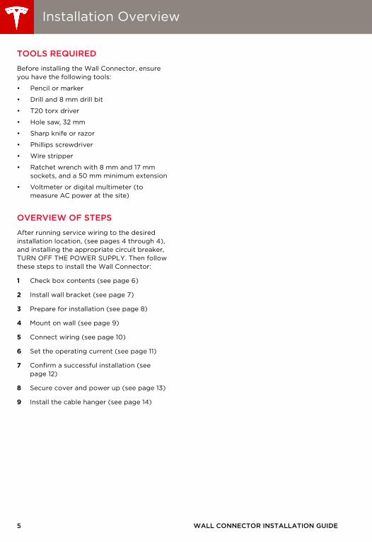
Installation Overview
TOOLS REQUIRED
Before installing the Wall Connector, ensure you have the following tools:
• Pencil or marker
• Drill and 8 mm drill bit
• T20 torx driver
• Hole saw, 32 mm
• Sharp knife or razor
• Phillips screwdriver
• Wire stripper
• Ratchet wrench with 8 mm and 17 mm sockets, and a 50 mm minimum extension
• Voltmeter or digital multimeter (to measure AC power at the site)
OVERVIEW OF STEPS
After running service wiring to the desired installation location, (see pages 4 through 4), and installing the appropriate circuit breaker, TURN OFF THE POWER SUPPLY. Then follow these steps to install the Wall Connector:
1 Check box contents (see page 6)
2 Install wall bracket (see page 7)
3 Prepare for installation (see page 8)
4 Mount on wall (see page 9)
5 Connect wiring (see page 10)
6 Set the operating current (see page 11)
7 Confirm a successful installation (see page 12)
8 Secure cover and power up (see page 13)
9 Install the cable hanger (see page 14)
WALL CONNECTOR INSTALLATION GUIDE
Wall_Connector_Install_Guide_Australia_Section_of_1046345-00-C.book Page 6 Thursday, July 17, 2014 10:47 AM
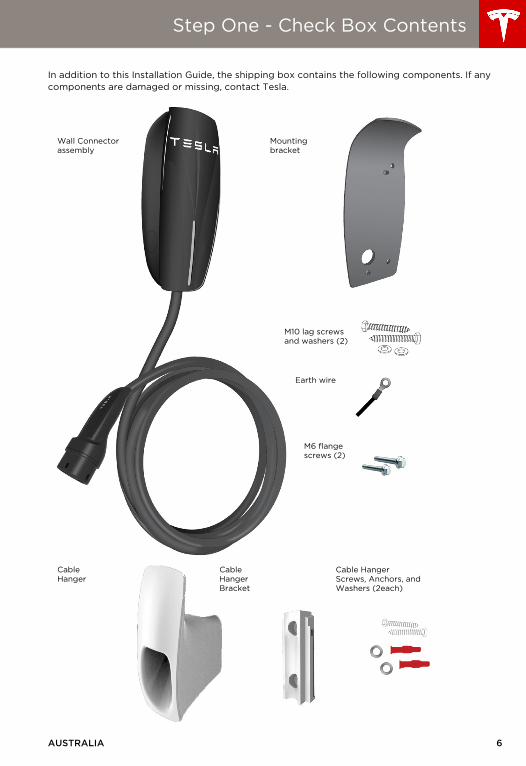
Step One - Check Box Contents
In addition to this Installation Guide, the shipping box contains the following components. If any components are damaged or missing, contact Tesla.
Wall Connector assembly
Mounting bracket
M10 lag screws and washers (2)
Earth wire
M6 flange screws (2)
CableHanger
CableHangerBracket
Cable HangerScrews, Anchors, and Washers (2each)
AUSTRALIA 6
7
Wall_Connector_Install_Guide_Australia_Section_of_1046345-00-C.book Page 7 Thursday, July 17, 2014 10:47 AM
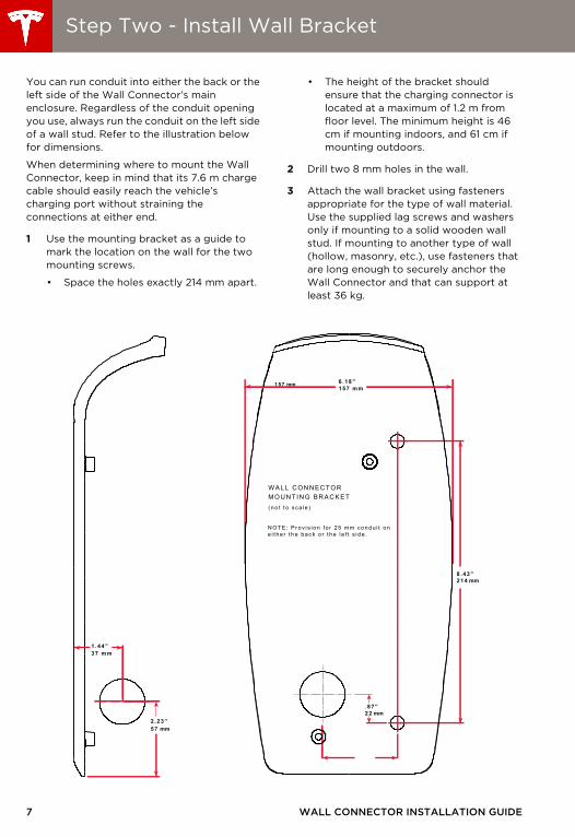
Step Two - Install Wall Bracket
You can run conduit into either the back or the left side of the Wall Connector’s main enclosure. Regardless of the conduit opening you use, always run the conduit on the left side of a wall stud. Refer to the illustration below for dimensions.
When determining where to mount the Wall Connector, keep in mind that its 7.6 m charge cable should easily reach the vehicle’s charging port without straining the connections at either end.
1 Use the mounting bracket as a guide to mark the location on the wall for the two mounting screws.
• Space the holes exactly 214 mm apart.
• The height of the bracket should ensure that the charging connector is located at a maximum of 1.2 m from floor level. The minimum height is 46 cm if mounting indoors, and 61 cm if mounting outdoors.
2 Drill two 8 mm holes in the wall.
3 Attach the wall bracket using fasteners appropriate for the type of wall material. Use the supplied lag screws and washers only if mounting to a solid wooden wall stud. If mounting to another type of wall (hollow, masonry, etc.), use fasteners that are long enough to securely anchor the Wall Connector and that can support at least 36 kg.
8 .43”214 mm
.87”22 mm
6.18”
WALL CONNECTORMOUNTI NG BRACKET( no t t o s c a l e )
N O T E: P r ov i s i on f o r 25 m m c ondu i t one i t he r t he bac k o r t he l e f t s i de .
157 mm
37 mm1.44”
57 mm2.23”
157 m m
WALL CONNECTOR INSTALLATION GUIDE
Wall_Connector_Install_Guide_Australia_Section_of_1046345-00-C.book Page 8 Thursday, July 17, 2014 10:47 AM
Step Three - Prepare for Installation
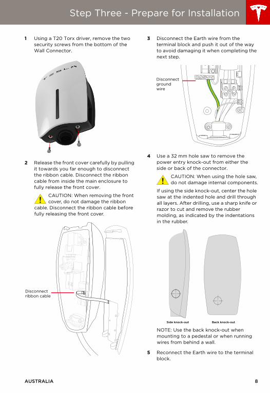
1 Using a T20 Torx driver, remove the two security screws from the bottom of the Wall Connector.
2 Release the front cover carefully by pulling it towards you far enough to disconnect the ribbon cable. Disconnect the ribbon cable from inside the main enclosure to fully release the front cover.
CAUTION: When removing the front cover, do not damage the ribbon
cable. Disconnect the ribbon cable before fully releasing the front cover.
3 Disconnect the Earth wire from the terminal block and push it out of the way to avoid damaging it when completing the next step.
4 Use a 32 mm hole saw to remove the power entry knock-out from either the side or back of the connector.
CAUTION: When using the hole saw, do not damage internal components.
If using the side knock-out, center the hole saw at the indented hole and drill through all layers. After drilling, use a sharp knife or razor to cut and remove the rubber molding, as indicated by the indentations in the rubber.
NOTE: Use the back knock-out when mounting to a pedestal or when running wires from behind a wall.
5 Reconnect the Earth wire to the terminal block.
Disconnectribbon cable
Disconnectgroundwire
Side knock-out Back knock-out
AUSTRALIA 8
9
Wall_Connector_Install_Guide_Australia_Section_of_1046345-00-C.book Page 9 Thursday, July 17, 2014 10:47 AM
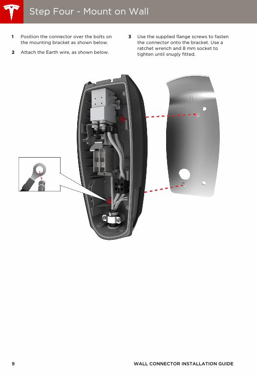
Step Four - Mount on Wall
1 Position the connector over the bolts on the mounting bracket as shown below.
2 Attach the Earth wire, as shown below.
3 Use the supplied flange screws to fasten the connector onto the bracket. Use a ratchet wrench and 8 mm socket to tighten until snugly fitted.
WALL CONNECTOR INSTALLATION GUIDE
AUSTRALIA 10
Step Five - Connect Wiring
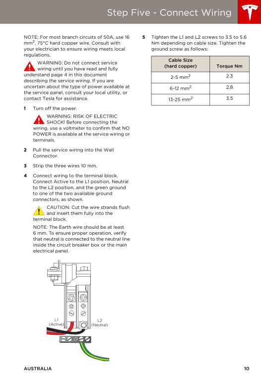
NOTE: For most branch circuits of 50A, use 16 mm2, 75°C hard copper wire. Consult with your electrician to ensure wiring meets local regulations.
WARNING: Do not connect service wiring until you have read and fully
understand page 4 in this document describing the service wiring. If you are uncertain about the type of power available at the service panel, consult your local utility, or contact Tesla for assistance.
1 Turn off the power.
WARNING: RISK OF ELECTRIC SHOCK! Before connecting the
wiring, use a voltmeter to confirm that NO POWER is available at the service wiring or terminals.
2 Pull the service wiring into the Wall Connector.
3 Strip the three wires 10 mm.
4 Connect wiring to the terminal block. Connect Active to the L1 position, Neutral to the L2 position, and the green ground to one of the two available ground connectors, as shown.
CAUTION: Cut the wire strands flush and insert them fully into the
terminal block.
NOTE: The Earth wire should be at least 6 mm. To ensure proper operation, verify that neutral is connected to the neutral line inside the circuit breaker box or the main electrical panel.
5 Tighten the L1 and L2 screws to 3.5 to 5.6 Nm depending on cable size. Tighten the ground screw as follows:
L1(Active)
L2(Neutral)
Cable Size(hard copper) Torque Nm
2-5 mm2 2.3
6-12 mm2 2.8
13-25 mm2 3.5
AUS_Contents.fm Page 10 Friday, July 18, 2014 12:28 PM

11 WALL CONNECTOR INSTALLATION GUIDE
Step Six - Set the Operating Current
Adjust the DIP switches to set the operating current. Use a pointed non-conductive object such as a plastic pen.
WARNING: Power MUST remain off before setting or changing DIP switches.
If you set DIP switches with the power on, not only is it dangerous because of the risk of electric shock, but the changes are not recognised.
SETTINGS
CIRCUIT BREAKER
Adjust the operating current based on the type of circuit breaker being used:
To determine the type of electrical breaker you need, examine the distribution panel/circuit breaker box to identify the amperage available at the installation site.
DIPswitches
Test Mode
Circuit Breaker Rating(Amps)
Maximum Current Supplied to Vehicle
(Amps)
50 40
40 32
20 16
16 10
1
2
3
4
1
2
3
4
1
2
3
4
1
2
3
4
16ABreaker
20ABreaker
40ABreaker
50ABreaker
AUS_Contents.fm Page 11 Friday, July 18, 2014 9:46 AM
AUSTRALIA 12
Step Seven - Confirm a Successful Installation
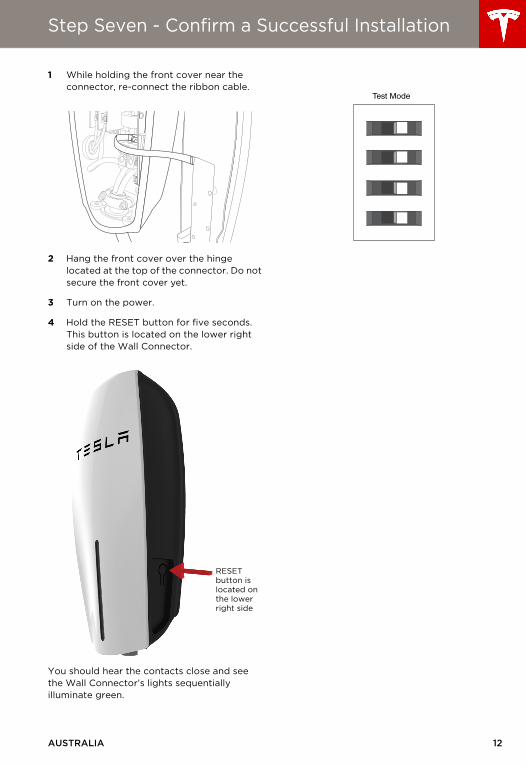
1 While holding the front cover near the connector, re-connect the ribbon cable.
2 Hang the front cover over the hinge located at the top of the connector. Do not secure the front cover yet.
3 Turn on the power.
4 Hold the RESET button for five seconds. This button is located on the lower right side of the Wall Connector.
You should hear the contacts close and see the Wall Connector’s lights sequentially illuminate green.
RESET button is located on the lower right side
Test Mode
AUS_Contents.fm Page 12 Friday, July 18, 2014 9:46 AM

13 WALL CONNECTOR INSTALLATION GUIDE
Step Eight - Secure Cover and Power Up
1 Reposition the front cover over the unit, aligning the five tabs on the back of the front cover with their corresponding slots. Starting at the bottom and working upwards, press firmly on both sides of the front cover until it clicks into place.
2 Using a T20 torx driver, re-attach the two security screws that you removed from the bottom of the Wall Connector in “Step Three - Prepare for Installation” on page 8.
3 Turn on the power.
4 Attempt to charge the car to ensure the Wall Connector is operating correctly and charging at the selected operating current. For instructions on how to charge, refer to the owner information provided with your vehicle.
AUS_Contents.fm Page 13 Friday, July 18, 2014 9:46 AM
AUSTRALIA 14
Step Nine - Install the Cable Hanger
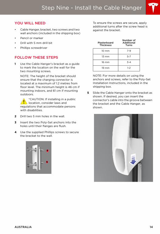
YOU WILL NEED
• Cable Hanger, bracket, two screws and two wall anchors (included in the shipping box)
• Pencil or marker
• Drill with 5 mm drill bit
• Phillips screwdriver
FOLLOW THESE STEPS
1 Use the Cable Hanger’s bracket as a guide to mark the location on the wall for the two mounting screws.
NOTE: The height of the bracket should ensure that the charging connector is located at a maximum of 1.2 metres from floor level. The minimum height is 46 cm if mounting indoors, and 61 cm if mounting outdoors.
*CAUTION: If installing in a public location, consider laws and
regulations that accommodate persons with disabilities.
2 Drill two 5 mm holes in the wall.
3 Insert the two Poly-Set anchors into the holes until their flanges are flush.
4 Use the supplied Phillips screws to secure the bracket to the wall.
To ensure the screws are secure, apply additional turns after the screw head is against the bracket.
NOTE: For more details on using the anchors and screws, refer to the Poly-Set Installation Instructions, included in the shipping box.
5 Slide the Cable Hanger onto the bracket as shown. If desired, you can insert the connector’s cable into the groove between the bracket and the Cable Hanger, as shown.
PlasterboardThickness
Number of Additional
Turns
10 mm 7-9
13 mm 5-7
16 mm 3-4
19 mm 1-2
AUS_Contents.fm Page 14 Friday, July 18, 2014 9:46 AM
15
Wall_Connector_Install_Guide_Australia_Section_of_1046345-00-C.book Page 15 Thursday, July 17, 2014 10:47 AM
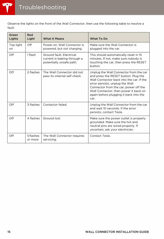
Troubleshooting
Observe the lights on the front of the Wall Connector, then use the following table to resolve a fault.
Green Lights
Red Light What It Means What To Do
Top light on
Off Power on. Wall Connector is powered, but not charging.
Make sure the Wall Connector is plugged into the car.
Off 1 flash Ground fault. Electrical current is leaking through a potentially unsafe path.
This should automatically reset in 15 minutes. If not, make sure nobody is touching the car, then press the RESET button.
Off 2 flashes The Wall Connector did not pass its internal self check.
Unplug the Wall Connector from the car and press the RESET button. Plug the Wall Connector back into the car. If the error persists, unplug the Wall Connector from the car, power off the Wall Connector, then power it back on again before plugging it back into the car.
Off 3 flashes Contactor failed. Unplug the Wall Connector from the car and wait 10 seconds. If the error persists, contact Tesla.
Off 4 flashes Ground lost. Make sure the power outlet is properly grounded. Make sure the hot and neutral pins are wired properly. If uncertain, ask your electrician.
Off 5 flashes or more
The Wall Connector requires servicing.
Contact Tesla.
WALL CONNECTOR INSTALLATION GUIDE
Wall_Connector_Install_Guide_Australia_Section_of_1046345-00-C.book Page 16 Thursday, July 17, 2014 10:47 AM
Maintenance and Repair
Always ensure that after charging, the charging cable is wrapped around the Wall Connector.
Regularly inspect the Wall Connector and charging cable for signs of damage. If damage is found, contact Tesla.
The Wall Connector contains no user-serviceable components. If the unit is not operating correctly, contact Tesla.
Wipe the outside of the Wall Connector, the charging cable, and the connector end of the charging cable with a clean dry cloth to remove any accumulation of dust and dirt.
WARNING: Turn off input power at the circuit breaker before cleaning the Wall
Connector.
WARNING: Do not use cleaning solvents, scouring powder, or any type of abrasive
pad to clean the Wall Connector, its charging cable, or the vehicle’s charging port.
CAUTION: To reduce the risk of electrical shock or equipment damage,
do not allow liquid to enter the Wall Connector while cleaning it.
AUSTRALIA 16

Wall_Connector_Install_Guide_Australia_Section_of_1046345-00-C.book Page 17 Thursday, July 17, 2014 10:47 AM

Cover_Tri_Language_Covers_and_Dividers.fm Page 11 Tuesday, July 15, 2014 1:41 PM

P/N: 1046345-00-C
Cover_Tri_Language_Covers_and_Dividers.fm Page 12 Tuesday, July 15, 2014 1:41 PM