Embed Size (px)
Citation preview
HIGH POWER WALL CONNECTOR
INSTALLATION GUIDE
INFORMATION ABOUT YOUR TESLA VEHICLE IS AVAILABLE AT:
www.teslamotors.com/mytesla
To contact Tesla call 1-877-79TESLA (1-877-798-3752)
For Roadside Assistance call 1-866-99TESLA (1-866-998-3752)
© 2012 TESLA MOTORS, INC. All rights reserved.
All information in this document and all MODEL S® software is subject to copyright and other intellectual property rights of Tesla Motors, Inc. and its licensors. This material may not
be modified, reproduced or copied, in whole or in part, without the prior written permission of Tesla Motors, Inc. and its licensors. Additional information is available upon request.
TESLA MOTORS®, TESLA ROADSTER®, ®, ®, ®, and MODEL S® are registered trademarks of Tesla Motors, Inc. in the United States. TESLA™ is a trademark of
Tesla Motors, Inc. in the United States and other countries. All other trademarks contained in this document are the property of their respective owners and their use herein does not
imply sponsorship or endorsement of their products or services. The unauthorized use of any trademark displayed in this document, the High Power Wall Connector or on the vehicle
is strictly prohibited.
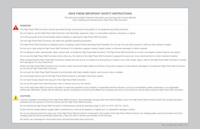
SAVE THESE IMPORTANT SAFETY INSTRUCTIONS
This document contains important instructions and warnings that must be followedwhen installing and maintaining the High Power Wall Connector.
WARNINGS:
The High Power Wall Connector must be grounded through a permanent wiring system or an equipment grounding conductor.
Do not install or use the High Power Wall Connector near flammable, explosive, harsh, or combustible materials, chemicals, or vapors.
Turn off input power at the circuit breaker before installing or cleaning the High Power Wall Connector.
Use the High Power Wall Connector only within the specified operating parameters.
The High Power Wall Connector is designed only for charging a Tesla vehicle (excluding Tesla Roadster). Do not use it for any other purpose or with any other vehicle or object.
Do not use or stop using the High Power Wall Connector if it is defective, appears cracked, frayed, broken or otherwise damaged, or fails to operate.
Do not attempt to open, disassemble, repair, tamper with, or modify the High Power Wall Connector. The High Power Wall Connector is not user serviceable. Contact Tesla for any repairs.
Do not use the High Power Wall Connector when either you, the vehicle or the High Power Wall Connector is exposed to severe rain, snow, electrical storm or other inclement weather.
When transporting the High Power Wall Connector, handle with care and do not subject it to strong force or impact or pull, twist, tangle, drag or step on the High Power Wall Connector to protect from damage to it or any components.
Protect the High Power Wall Connector from moisture, water, liquid and foreign objects at all times. If any exist or appear to have entered, damaged or corroded the High Power Wall Connector, do not use the High Power Wall Connector.
Do not touch the High Power Wall Connector’s end terminals with sharp metallic objects, such as wire, tools or needles.
Do not forcefully fold any part of the High Power Wall Connector or damage it with sharp objects.
Do not insert foreign objects into any part of the High Power Wall Connector.
Do not use the High Power Wall Connector when a vehicle cover is on the vehicle.
Use of the High Power Wall Connector may affect or impair the operation of any medical or implantable electronic devices, such as an implantable cardiac pacemaker or an implantable cardioverter defibrillator. Check with the electronic device manufacturer concerning the effects that charging may have on such electronic device before using the High Power Wall Connector.
CAUTIONS:
Incorrect installation and testing of the High Power Wall Connector could potentially damage either the vehicle’s Battery and/or the High Power Wall Connector itself. Any resulting damage is excluded from the warranty for both the vehicle and the High Power Wall Connector.
Do not operate the High Power Wall Connector in temperatures outside its operating range of -22°F to 113°F (-30°C to +45°C).
Ensure that the charge station’s supply cable is positioned so it will not be stepped on, tripped over, or subjected to damage or stress.
Do not use cleaning solvents to clean any of the High Power Wall Connector’s components. The outside of the High Power Wall Connector, the charging cable, and the connector end of the charging cable should be periodically wiped with a clean dry cloth to remove accumulation of dirt and dust.
Be careful not to damage the circuit board when removing the power entry knock-out.
P/N: 1018667-00-A REV: 1.00
PRODUCT SPECIFICATIONS
All specifications and descriptions contained in this document are verified to be accurate at the time of printing. However, because continuous improvement is a goal at Tesla, we reserve the right to make product modifications at any time.
FCC DECLARATION OF CONFORMITY
This device complies with Part 15 of the FCC rules. Operation is subject to the following two conditions: (1) This device may not cause harmful interference, and (2) this device must accept any interference received, including interference that may cause undesired operation.
Radio and Television Interference
The equipment described in this manual has been designed to protect against Radio Frequency Interference (RFI). However, there are some instances where high powered radio signals or nearby RF-producing equipment (such as digital phones, RF communications equipment, etc.) could affect operations.
If interference to your High Power Wall Connector is suspected, relocate or turn off nearby electrical appliances during charging, before contacting Tesla for assistance.
Important!
Changes or modifications to this product not authorized by Tesla could void the FCC compliance.
HIG
H P
OW
ER
WA
LL
CO
NN
EC
TOR
1
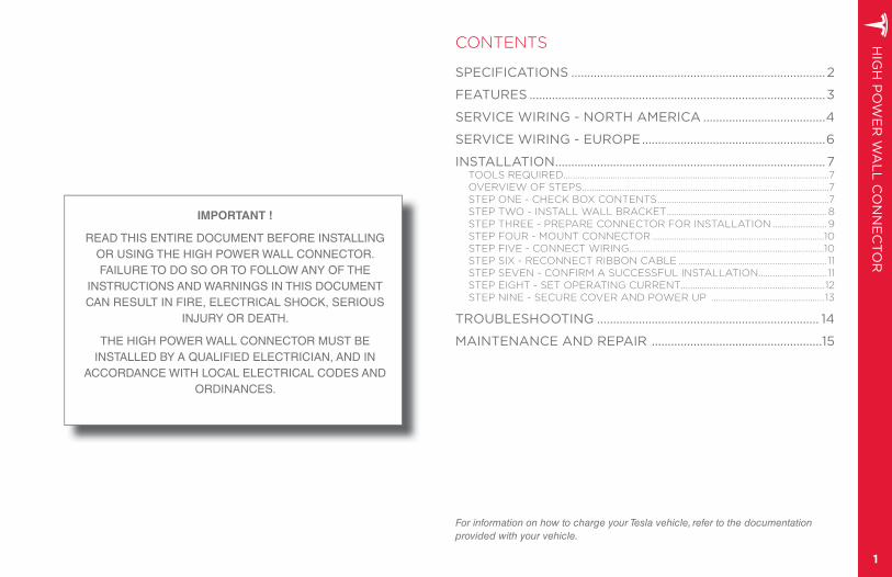
CONTENTS
SPECIFICATIONS ...............................................................................2
FEATURES ............................................................................................3
SERVICE WIRING - NORTH AMERICA ......................................4
SERVICE WIRING - EUROPE .........................................................6
INSTALLATION ....................................................................................7TOOLS REQUIRED.................................................................................................................7OVERVIEW OF STEPS .........................................................................................................7STEP ONE - CHECK BOX CONTENTS .........................................................................7STEP TWO - INSTALL WALL BRACKET .................................................................... 8STEP THREE - PREPARE CONNECTOR FOR INSTALLATION ....................... 9STEP FOUR - MOUNT CONNECTOR .........................................................................10STEP FIVE - CONNECT WIRING ...................................................................................10STEP SIX - RECONNECT RIBBON CABLE ............................................................... 11STEP SEVEN - CONFIRM A SUCCESSFUL INSTALLATION ............................. 11STEP EIGHT - SET OPERATING CURRENT ............................................................. 12STEP NINE - SECURE COVER AND POWER UP ................................................ 13
TROUBLESHOOTING ..................................................................... 14
MAINTENANCE AND REPAIR .....................................................15
For information on how to charge your Tesla vehicle, refer to the documentation provided with your vehicle.
IMPORTANT !
READ THIS ENTIRE DOCUMENT BEFORE INSTALLING OR USING THE HIGH POWER WALL CONNECTOR. FAILURE TO DO SO OR TO FOLLOW ANY OF THE
INSTRUCTIONS AND WARNINGS IN THIS DOCUMENT CAN RESULT IN FIRE, ELECTRICAL SHOCK, SERIOUS
INJURY OR DEATH.
THE HIGH POWER WALL CONNECTOR MUST BE INSTALLED BY A QUALIFIED ELECTRICIAN, AND IN
ACCORDANCE WITH LOCAL ELECTRICAL CODES AND ORDINANCES.
HIG
H P
OW
ER
WA
LL
CO
NN
EC
TOR
2
SP
EC
IFIC
AT
ION
S
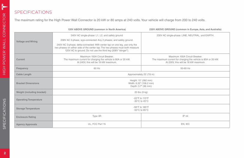
SPECIFICATIONS
The maximum rating for the High Power Wall Connector is 20 kW or 80 amps at 240 volts. Your vehicle will charge from 200 to 240 volts.
120V ABOVE GROUND (common in North America) 230V ABOVE GROUND (common in Europe, Asia, and Australia)
Voltage and Wiring
240V AC single-phase: L1, L2, and safety ground
208V AC 3-phase, wye-connected: Any 2 phases, and safety ground.
240V AC 3-phase, delta-connected: With center tap on one leg, use only the two phases on either side of the center tap. The two phases must both measure
120V AC to ground. Do not use the third leg (208V “stinger”).
230V AC single-phase: LINE, NEUTRAL, and EARTH.
Current
Maximum 100A Circuit Breaker. The maximum current for charging the vehicle is 80A or 20 kW.
At 240V, this will be 19 kW maximum.
Maximum 100A Circuit Breaker.The maximum current for charging the vehicle is 80A or 20 kW.
At 230V, this will be 18 kW maximum.
Frequency 60 Hz 50-60 Hz
Cable Length Approximately 25’ (7.6 m)
Bracket Dimensions
Height: 15” (382 mm)Width: 6.22” (158.2 mm)
Depth: 3.7” (96 mm)
Weight (including bracket) 20 lbs (9 kg)
Operating Temperature-22°F to 113°F-30°C to 45°C
Storage Temperature-58°F to 185°F-50°C to 85°C
Enclosure Rating Type 3R IP 44
Agency Approvals UL, FCC Part 15 EN, IEC
HIG
H P
OW
ER
WA
LL
CO
NN
EC
TOR
3
FE
AT
UR
ES
OPTIONAL CIRCUIT RATINGS
For the fastest charging, using a circuit breaker rated for 100 amps is recommended. In certain home or office locations, this level of power isn’t readily available. Therefore, you can adjust the current setting on the High Power Wall Connector for 40 to 100 amp breakers (see page 12).
SELF-MONITORING AND RECOVERY
The High Power Wall Connector has a ground monitoring circuit that continuously checks for the presence of a safe ground connection and automatically recovers from faults. Manual testing and resetting is not required.
Temporary problems such as ground faults or utility power surges are overcome automatically. If a GFCI fault occurs that interrupts charging, the High Power Wall Connector automatically tries to clear the fault and re-attempt charging.
If the problem is immediately sensed a second time, the High Power Wall Connector waits 15 minutes before trying to charge. This process repeats eight times and if all attempts are unsuccessful, power is removed and no further attempts are made. In this case, you’ll see a red error light on the front panel (refer to the troubleshooting table on page 14). It is recommended that when you see a red error light, you power off the High Power Wall Connector and then power it back on again.
POWER OUTAGES
If a power outage occurs, the High Power Wall Connector automatically resumes charging when power is restored. If the charging cable is plugged into the vehicle when power is restored, the lights blink and the unit does not energize the charging cable for approximately 15 seconds to 3 minutes. This prevents the utility grid from experiencing a large surge when power is restored, allowing the vehicle to begin drawing current at random times, rather than all at once.
HIG
H P
OW
ER
WA
LL
CO
NN
EC
TOR
4
120V ABOVE GROUND
For most branch circuits of 100A, use 3 AWG (26.7 mm2), 167°F (75°C) copper wire. Ground wiring can be a maximum of 4 AWG. If your ground wiring does not fit into the bus, use a wire nut or other suitable connection method. For installations less than 100A, use conductors that are sized according to local electrical codes.
Run 1” (25 mm) conduit on the left side of a wall stud. The conduit fits into the opening on either the back or the left side of the High Power Wall Connector as described on page 10.
The service connections described next are primarily used in North America. For service connections used in Europe and Australia (sometimes known as “TT Power Grid”), refer to page 6.
Only three wires are connected, but care must be taken that the service transformer secondary connection is definitely known, and that the three wires from the main circuit breaker panel are correctly connected and labeled. The illustrations shown are the most commonly used wiring formats.
NOTE: The L1, L2, and GND outputs labelled on the illustrations correspond to the inputs on the High Power Wall Connector.
WARNINGS:
The High Power Wall Connector is a single-phase device. Do not connect all 3 phases of a 3-phase feed.
Before installing the High Power Wall Connector, identify the type of utility service connection available on site. If you are unsure about the type of connection available at the service panel, consult the local utility company, or contact Tesla for assistance.
CAUTIONS:
The two phases used must each measure 120V to Neutral. Earth Ground must be connected to Neutral at only one point, usually at the Service Entry Breaker Panel.
If a 240V 3-phase feed is from a Delta-connected secondary, the leg used must have a center tap. This center tap must be grounded. Only the two phases on either side of the center-tapped leg can be used.
SE
RV
ICE
WIR
ING
- N
OR
TH
AM
ER
ICA
Ground connection
Always connect the Neutral at the service to Earth ground. Ground fault protection is not possible unless the Neutral (center tap on the service transformer) is connected to an Earth ground.
If Ground is not provided by the electrical service, you must install a grounding stake nearby. The grounding stake must be connected to the ground bar in the main breaker panel, and Neutral connected to Ground at that point.
WARNING: Follow local electrical codes when installing the grounding stake.
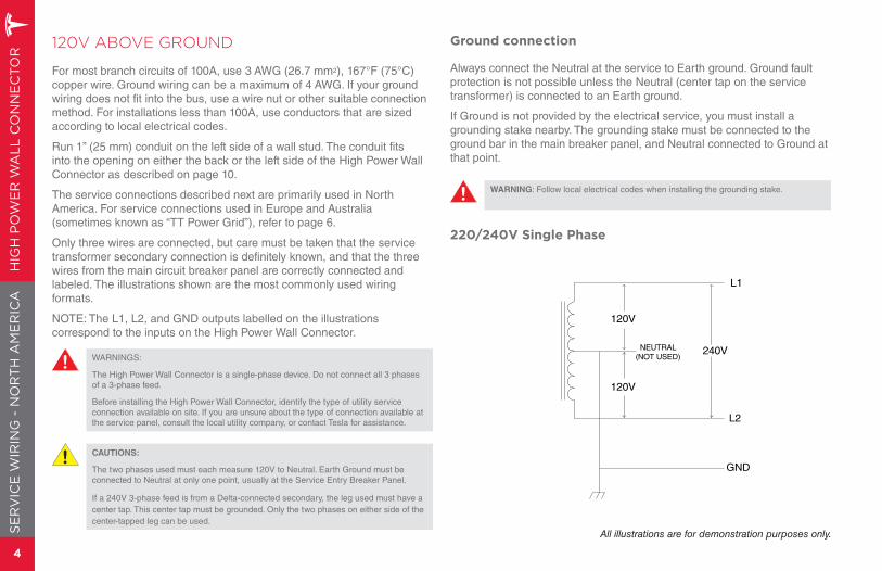
220/240V Single Phase
120V
120V
NEUTRAL(NOT USED)
L1
L2
GND
240V
All illustrations are for demonstration purposes only.
HIG
H P
OW
ER
WA
LL
CO
NN
EC
TOR
5
SE
RV
ICE
WIR
ING
- NO
RT
H A
ME
RIC
A
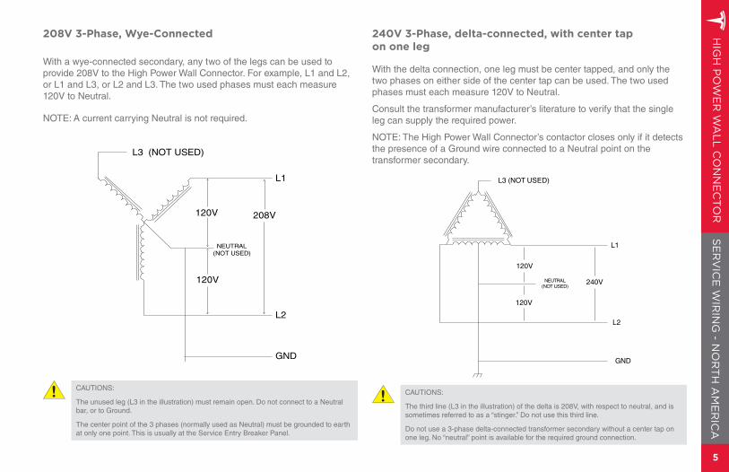
208V 3-Phase, Wye-Connected
With a wye-connected secondary, any two of the legs can be used to provide 208V to the High Power Wall Connector. For example, L1 and L2, or L1 and L3, or L2 and L3. The two used phases must each measure 120V to Neutral.
NOTE: A current carrying Neutral is not required.
120V
120V
NEUTRAL(NOT USED)
GND
L1
L2
L3 (NOT USED)
208V
CAUTIONS:
The unused leg (L3 in the illustration) must remain open. Do not connect to a Neutral bar, or to Ground.
The center point of the 3 phases (normally used as Neutral) must be grounded to earth at only one point. This is usually at the Service Entry Breaker Panel.
240V 3-Phase, delta-connected, with center tap on one leg
With the delta connection, one leg must be center tapped, and only the two phases on either side of the center tap can be used. The two used phases must each measure 120V to Neutral.
Consult the transformer manufacturer’s literature to verify that the single leg can supply the required power.
NOTE: The High Power Wall Connector’s contactor closes only if it detects the presence of a Ground wire connected to a Neutral point on the transformer secondary.
L3 (NOT USED)
L1
L2
GND
NEUTRAL(NOT USED)
120V
120V
240V
CAUTIONS:
The third line (L3 in the illustration) of the delta is 208V, with respect to neutral, and is sometimes referred to as a “stinger.” Do not use this third line.
Do not use a 3-phase delta-connected transformer secondary without a center tap on one leg. No “neutral” point is available for the required ground connection.
HIG
H P
OW
ER
WA
LL
CO
NN
EC
TOR
6
230V ABOVE GROUND
For most branch circuits of 100A, use 3 AWG (26.7 mm2), 75°C (167°F) copper wire. For installations less than 100A, use conductors that are sized according to local electrical codes. Ground wiring can be a maximum of 4 AWG. If your ground wiring does not fit into the bus, use a wire nut or other suitable connection method.
Run 25 mm (1”) conduit on the left side of a wall stud. The conduit fits into the opening on either the back or the left side of the High Power Wall Connector as described on page 10.
The service connections described below are primarily used in Europe and Australia (sometimes known as “TT Power Grid”). For service connections used in North America, refer to page 4.
When connecting the Line and Neutral wires, care must be taken that the service transformer secondary connection is definitely known, and the wires from the main circuit breaker panel are correctly connected and labeled. The illustrations provided show the most commonly used wiring format in Europe.
NOTE: The Line, Neutral, and Earth outputs labeled on the illustrations correspond to the inputs on the High Power Wall Connector.
WARNINGS:
The High Power Wall Connector is a single-phase device. Do not connect all 3 phases of a 3-phase feed.
Before installing the High Power Wall Connector, identify the type of utility service connection available on site. If you are unsure about the type of connection available at the service panel, consult the local utility company, or contact Tesla for assistance.
CAUTION: The Line connection must measure 230V RMS to Neutral. Earth must also be connected to the High Power Wall Connector.
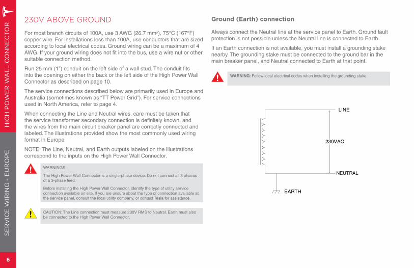
Ground (Earth) connection
Always connect the Neutral line at the service panel to Earth. Ground fault protection is not possible unless the Neutral line is connected to Earth.
If an Earth connection is not available, you must install a grounding stake nearby. The grounding stake must be connected to the ground bar in the main breaker panel, and Neutral connected to Earth at that point.
WARNING: Follow local electrical codes when installing the grounding stake.
NEUTRAL
LINE
EARTH
230VAC
SE
RV
ICE
WIR
ING
- E
UR
OP
E
HIG
H P
OW
ER
WA
LL
CO
NN
EC
TOR
7
INS
TAL
LA
TIO
N
TOOLS REQUIRED
T20 torx driver
Hole saw (1 ¼ ” / 32 mm)
Ratchet wrench with 8 mm and 17 mm sockets, and a 2” (minimum)extension
Sharp knife or razor
Voltmeter or Digital Multimeter (to measure AC power at the site)
OVERVIEW OF STEPS
After running service wiring to the desired location using 1” (25 mm) conduit as described on the previous pages, TURN OFF THE POWER SUPPLY. Then follow these steps to install the High Power Wall Connector:
1. Check box contents.
2. Install wall bracket.
3. Prepare connector for installation.
4. Mount connector.
5. Connect wiring.
6. Confirm a successful installation.
7. Set operating current.
8. Secure cover and power up.
These steps are detailed next.
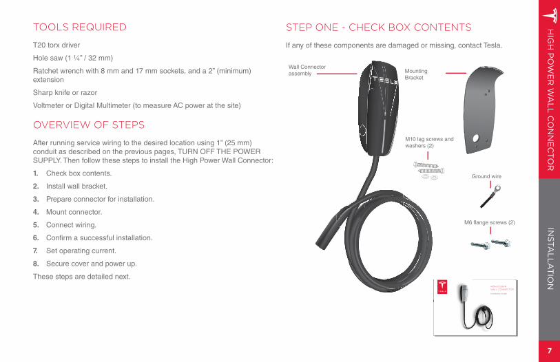
Wall Connector assembly Mounting
Bracket
M6 flange screws (2)
M10 lag screws and washers (2)
INSTALLATION
STEP ONE - CHECK BOX CONTENTS
If any of these components are damaged or missing, contact Tesla.
Ground wire
HIGH POWER WALL CONNECTOR
Installation Guide
HIG
H P
OW
ER
WA
LL
CO
NN
EC
TOR
8
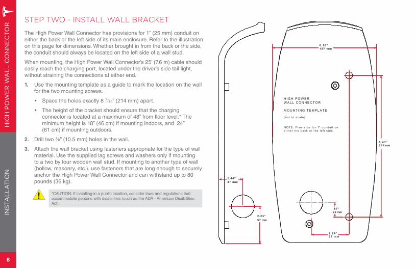
STEP TWO - INSTALL WALL BRACKET
The High Power Wall Connector has provisions for 1” (25 mm) conduit on either the back or the left side of its main enclosure. Refer to the illustration on this page for dimensions. Whether brought in from the back or the side, the conduit should always be located on the left side of a wall stud.
When mounting, the High Power Wall Connector’s 25’ (7.6 m) cable should easily reach the charging port, located under the driver’s side tail light, without straining the connections at either end.
1. Use the mounting template as a guide to mark the location on the wall for the two mounting screws.
• Space the holes exactly 8 ⁄” (214 mm) apart.
• The height of the bracket should ensure that the charging connector is located at a maximum of 48” from floor level.* The minimum height is 18” (46 cm) if mounting indoors, and 24” (61 cm) if mounting outdoors.
2. Drill two ⅜ ” (10.5 mm) holes in the wall.
3. Attach the wall bracket using fasteners appropriate for the type of wall material. Use the supplied lag screws and washers only if mounting to a two by four wooden wall stud. If mounting to another type of wall (hollow, masonry, etc.), use fasteners that are long enough to securely anchor the High Power Wall Connector and can withstand up to 80 pounds (36 kg).
*CAUTION: If installing in a public location, consider laws and regulations that accommodate persons with disabilities (such as the ADA - American Disabilities Act).
INS
TAL
LA
TIO
N
8 .43”214 mm
.87”22 mm
2.24”57 mm
6.18”
H I G H P O W E RWA L L C O N N E C T O R
MO U N T I N G T E M P L A T E
( no t t o sca l e )
N O TE: P rov i s i on f o r 1 " condu i t one i t he r t he back o r t he l e f t s i de .
37 mm1.44”
57 mm2.23”
157 mm
HIG
H P
OW
ER
WA
LL
CO
NN
EC
TOR
9
INS
TAL
LA
TIO
N
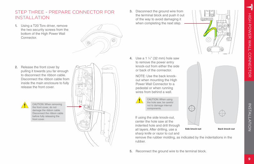
STEP THREE - PREPARE CONNECTOR FOR INSTALLATION
1. Using a T20 Torx driver, remove the two security screws from the bottom of the High Power Wall Connector.
2. Release the front cover by pulling it towards you far enough to disconnect the ribbon cable. Disconnect the ribbon cable from inside the main enclosure to fully release the front cover.
CAUTION: When removing the front cover, do not damage the ribbon cable. Disconnect the ribbon cable before fully releasing the front cover.
3. Disconnect the ground wire from the terminal block and push it out of the way to avoid damaging it when completing the next step.
4. Use a 1 ¼ ” (32 mm) hole saw to remove the power entry knock-out from either the side or back of the connector.
NOTE: Use the back knock-out when mounting the High Power Wall Connector to a pedestal or when running wires from behind a wall.
CAUTION: When using the hole saw, be careful not to damage internal components.
If using the side knock-out, center the hole saw at the indented hole and drill through all layers. After drilling, use a sharp knife or razor to cut and remove the rubber molding, as indicated by the indentations in the rubber.
5. Reconnect the ground wire to the terminal block.
Side knock-out Back knock-out
HIG
H P
OW
ER
WA
LL
CO
NN
EC
TOR
10
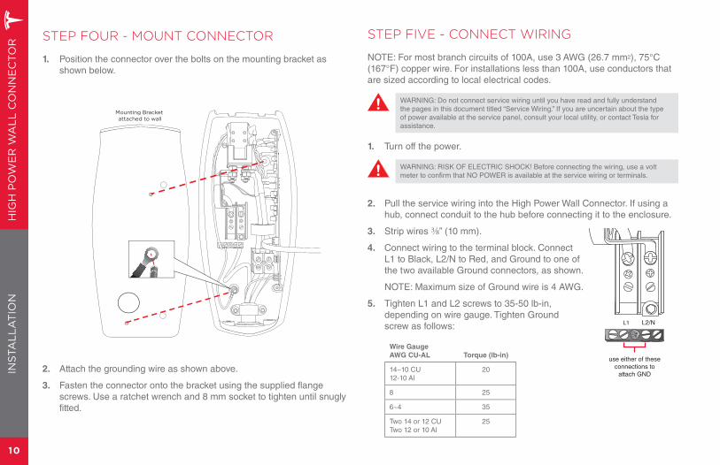
STEP FOUR - MOUNT CONNECTOR
1. Position the connector over the bolts on the mounting bracket as shown below.
2. Attach the grounding wire as shown above.
3. Fasten the connector onto the bracket using the supplied flange screws. Use a ratchet wrench and 8 mm socket to tighten until snugly fitted.
Mounting Bracket attached to wall
STEP FIVE - CONNECT WIRING
NOTE: For most branch circuits of 100A, use 3 AWG (26.7 mm2), 75°C (167°F) copper wire. For installations less than 100A, use conductors that are sized according to local electrical codes.
WARNING: Do not connect service wiring until you have read and fully understand the pages in this document titled “Service Wiring.” If you are uncertain about the type of power available at the service panel, consult your local utility, or contact Tesla for assistance.
1. Turn off the power.
WARNING: RISK OF ELECTRIC SHOCK! Before connecting the wiring, use a volt meter to confirm that NO POWER is available at the service wiring or terminals.
2. Pull the service wiring into the High Power Wall Connector. If using a hub, connect conduit to the hub before connecting it to the enclosure.
3. Strip wires ⅜ ” (10 mm).
4. Connect wiring to the terminal block. Connect L1 to Black, L2/N to Red, and Ground to one of the two available Ground connectors, as shown.
NOTE: Maximum size of Ground wire is 4 AWG.
5. Tighten L1 and L2 screws to 35-50 lb-in, depending on wire gauge. Tighten Ground screw as follows:
Wire Gauge
AWG CU-AL Torque (lb-in)
14~10 CU12-10 Al
20
8 25
6~4 35
Two 14 or 12 CUTwo 12 or 10 Al
25
INS
TAL
LA
TIO
N
L1 L2/N
use either of theseconnections to
attach GND
HIG
H P
OW
ER
WA
LL
CO
NN
EC
TOR
11
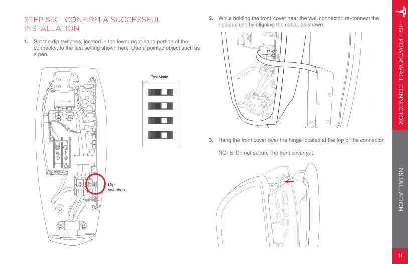
2. While holding the front cover near the wall connector, re-connect the ribbon cable by aligning the cable, as shown.
3. Hang the front cover over the hinge located at the top of the connector.
NOTE: Do not secure the front cover yet.
INS
TAL
LA
TIO
N
STEP SIX - CONFIRM A SUCCESSFUL INSTALLATION
1. Set the dip switches, located in the lower right-hand portion of the connector, to the test setting shown here. Use a pointed object such as a pen.
Dipswitches
Test Mode
HIG
H P
OW
ER
WA
LL
CO
NN
EC
TOR
12
INS
TAL
LA
TIO
N
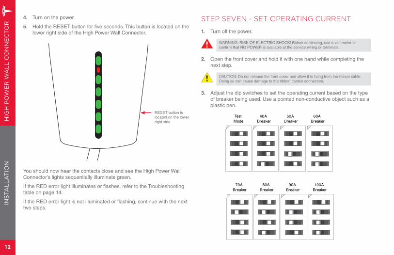
STEP SEVEN - SET OPERATING CURRENT
1. Turn off the power.
WARNING: RISK OF ELECTRIC SHOCK! Before continuing, use a volt meter to confirm that NO POWER is available at the service wiring or terminals.
2. Open the front cover and hold it with one hand while completing the next step.
CAUTION: Do not release the front cover and allow it to hang from the ribbon cable.Doing so can cause damage to the ribbon cable’s connectors.
3. Adjust the dip switches to set the operating current based on the type of breaker being used. Use a pointed non-conductive object such as a plastic pen.
Test Mode
40A Breaker
50A Breaker
60A Breaker
70A Breaker
80A Breaker
90A Breaker
100A Breaker
4. Turn on the power.
5. Hold the RESET button for five seconds. This button is located on the lower right side of the High Power Wall Connector.
You should now hear the contacts close and see the High Power Wall Connector’s lights sequentially illuminate green.
If the RED error light illuminates or flashes, refer to the Troubleshooting table on page 14.
If the RED error light is not illuminated or flashing, continue with the next two steps.
RESET button is located on the lower right side
HIG
H P
OW
ER
WA
LL
CO
NN
EC
TOR
13
INS
TAL
LA
TIO
N
STEP EIGHT - SECURE COVER AND POWER UP
1. Reposition the front cover over the unit, aligning the five tabs on the back of the front cover with their corresponding slots. Starting at the bottom and working upwards, press firmly on both sides of the front cover until it clicks into place.
2. Using a T20 torx driver, re-attach the two security screws that you removed in STEP THREE.
3. Turn on the power.
YOU HAVE NOW FINISHED INSTALLING THE HIGH POWER WALL CONNECTOR. YOU ARE READY TO INSTALL THE CABLE DECK. FOR DETAILS, REFER TO THE INSTALLATION INSTRUCTIONS PROVIDED WITH THE CABLE DOCK.
HIG
H P
OW
ER
WA
LL
CO
NN
EC
TOR
14
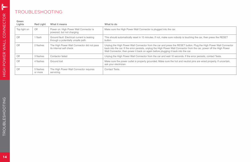
TROUBLESHOOTING
Green
Lights Red Light What it means What to do
Top light on Off Power on. High Power Wall Connector is powered, but not charging.
Make sure the High Power Wall Connector is plugged into the car.
Off 1 flash Ground fault. Electrical current is leaking through a potentially unsafe path.
This should automatically reset in 15 minutes. If not, make sure nobody is touching the car, then press the RESET button.
Off 2 flashes The High Power Wall Connector did not pass its internal self check.
Unplug the High Power Wall Connector from the car and press the RESET button. Plug the High Power Wall Connector back into the car. If the error persists, unplug the High Power Wall Connector from the car, power off the High Power Wall Connector, then power it back on again before plugging it back into the car.
Off 3 flashes Contactor failed Unplug the High Power Wall Connector from the car and wait 10 seconds. If the error persists, contact Tesla.
Off 4 flashes Ground lost Make sure the power outlet is properly grounded. Make sure the hot and neutral pins are wired properly. If uncertain, ask your electrician.
Off 5 flashes or more
The High Power Wall Connector requires servicing.
Contact Tesla.
TR
OU
BL
ES
HO
OT
ING
HIG
H P
OW
ER
WA
LL
CO
NN
EC
TOR
15
MA
INT
EN
AN
CE
AN
D R
EPA
IRMAINTENANCE & SUPPORT
MAINTENANCE AND REPAIR
Always ensure that after charging, the charging cable is returned to the cable hanger and the charging connector is clear of the floor.
Regularly inspect the High Power Wall Connector and charging cable for signs of damage. If damage is found, contact Tesla.
The High Power Wall Connector contains no user-serviceable components. If the unit is not operating correctly, contact Tesla.
Wipe the outside of the High Power Wall Connector, the charging cable, and the connector end of the charging cable with a clean dry cloth to remove any accumulation of dust and dirt.
WARNINGS:
Turn off input power at the circuit breaker before cleaning the High Power Wall Connector.
Do not use cleaning solvents, scouring powder, or any type of abrasive pad to clean the High Power Wall Connector, its charging cable or the vehicle’s charging port.
To reduce the risk of electrical shock or equipment damage, do not allow liquid to enter the High Power Wall Connector while cleaning it.
QUESTIONS?
Contact Tesla at 1-877-79-TESLA.
CONNECTOR LIMITED WARRANTY
Subject to the exclusions and limitations described below, the Connector Limited Warranty covers the repair or replacement necessary to correct any manufacturing defects in the factory-supplied High Power Wall Connector that occurs under normal use for a period of 12 months from the date of invoice to the customer.
This Connector Limited Warranty does not cover any damage or malfunction directly or indirectly caused by, due to or resulting from normal wear or deterioration, abuse, misuse, negligence, accident, lack of or improper installation, use, maintenance, storage or transport, including, but not limited to, any of the following:
• Failure to follow the instructions, maintenance and warnings in this document;
• External factors including but not limited to objects striking the High Power Wall Connector, faulty and damaged power outlets, the environment or an act of God, including, but not limited to, fire, earthquake, water, lightning and other environmental conditions;
• General appearance or damage to paint including chips, scratches, dents and cracks;
• Failure to contact Tesla upon discovery of a defect covered by this Connector Limited Warranty;
• Use of faulty power receptacles;
• Any repair, alteration or modification of the High Power Wall Connector or any part, or the installation or use of any parts or accessories, made by a person or facility not authorized or certified to do so;
• Lack of or improper repair or maintenance, including use of non-genuine Tesla accessories or parts; and
• Use for commercial purposes.
Although Tesla does not require you to perform all maintenance, service or repairs at a Tesla Service Center or Tesla authorized repair facility,
this Connector Limited Warranty may be voided or coverage may be excluded due to lack of or improper maintenance, service or repairs. Tesla Service Centers and Tesla authorized repair facilities have special training, expertise, tools and supplies with respect to the High Power Wall Connector and, in certain cases, may employ the only persons or be the only facilities authorized or certified to work on the High Power Wall Connector. Tesla strongly recommends that you have all maintenance, service and repairs done at a Tesla Service Center or Tesla authorized repair facility in order to avoid voiding, or having coverage excluded under, this Connector Limited Warranty.
LIMITS OF LIABILITY
Implied and express warranties and conditions arising under applicable state or provincial laws or federal statute or otherwise in law or in equity, if any, including, but not limited to, implied warranties and conditions of merchantability or merchantable quality, fitness for a particular purpose, durability, or those arising by a course of dealing or usage of trade, are disclaimed to the fullest extent allowable by law, or limited in duration to the term of this Connector Limited Warranty. The performance of necessary repairs and parts replacement is the exclusive remedy under this Connector Limited Warranty or any implied warranties. Liability is limited to the reasonable price for repair or replacement of the High Power Wall Connector, not to exceed the manufacturer’s suggested retail price. Replacement may be made with parts of like kind and quality, including non-original manufacturer’s parts or remanufactured parts, as necessary.
In no event shall liability for any defect under this Connector Limited Warranty exceed the fair market value of the High Power Wall Connector at the time immediately preceding the discovery of the defect. In addition, the sum of all benefits payable under this Connector Limited Warranty shall not exceed the price you paid for the High Power Wall Connector.
Tesla does not authorize any person or entity to create for it any other obligations or liability in connection with this Connector Limited Warranty. The decision of whether to repair or replace a part or to use a new or remanufactured part will be made by Tesla, in its sole discretion.
Tesla hereby disclaims any and all indirect, incidental, special and consequential damages arising out of or relating to the High Power Wall Connector, including, but not limited to, transportation to and from a Tesla Authorized Service Center, loss of High Power Wall Connector or vehicle value, loss of time, loss of income, loss of use, loss of personal or commercial property, inconvenience or aggravation, emotional distress or harm, commercial loss (including but not limited to lost profits or earnings), towing charges, bus fares, vehicle rental, service call charges, gasoline expenses, lodging expenses, damage to tow vehicle, and incidental charges such as telephone calls, facsimile transmissions, and mailing expenses.
The above limitations and exclusions shall apply whether your claim is in contract, tort (including negligence and gross negligence), breach of warranty or condition, misrepresentation (whether negligent or otherwise) or otherwise at law or in equity, even if Tesla is advised of the possibility of such damages or such damages are reasonably foreseeable.
WARRANTY ENFORCEMENT LAWS AND DISPUTE RESOLUTION
To the fullest extent allowed by the law of your jurisdiction, Tesla requires that you first provide Tesla, during the applicable warranty period specified in this Connector Limited Warranty, with written notification of any defects you have experienced, within a reasonable time to allow Tesla an opportunity to make any needed repairs, and to submit to our dispute settlement program before you pursue any remedy under these laws. Please send your written notification to:
Tesla Motors, Inc.3500 Deer Creek RoadPalo Alto, California 94304Attention: Vehicle Service
Please include the following information:
• High Power Wall Connector and Invoice Date;
• Your name and contact information;
• Name and location of the Tesla Store and/or Tesla Service Center nearest you;
• Description of the defect; and
• History of the attempts you have made with Tesla to resolve the concern, or of any repairs or services that were not performed by Tesla.
In the event any disputes, differences or controversies arise between you and Tesla related to this Connector Limited Warranty, Tesla will explore all possibilities for an amicable settlement. In case an amicable settlement is not reached, Tesla offers a dispute settlement program through:
NATIONAL CENTER FOR DISPUTE SETTLEMENT (“NCDS”)P.O. Box 526Mt. Clemens, MI 480461-866-629-3204
Tesla requires that you submit your dispute to our dispute settlement program and wait for a decision to be issued prior to pursuing any remedy under federal or state laws (including 15 U.S.C. Section 2310 or California Civil Code Section 1793.22(b)), although you may be entitled to pursue a remedy without submitting under certain state laws or if you pursue any rights or remedies not created by these laws. This dispute settlement program administered by NCDS is free of charge to you and is conducted by local NCDS professionals who are trained and experienced in mediation and arbitration.
NCDS resolves disputes involving this Connector Limited Warranty which arise during the applicable warranty period specified in this Connector Limited Warranty. You must file a request for arbitration with NCDS within 60 days (or 6 months in certain jurisdictions) of the expiration of the applicable warranty period, provided you sent written notice to Tesla, as specified above, of the alleged defect during the applicable warranty period.
To initiate arbitration, you must contact NCDS at 1-866-629-3204 or P.O. Box 526, Mt. Clemens, MI 48046, and complete an NCDS customer claim form and mail it to NCDS. Please also provide a copy of your written
notification sent to Tesla and/or all information required in such notification specified above, your desired resolution, and all receipts if requesting reimbursement. Upon receipt of your request, NCDS will contact you regarding the status of your case and provide you with additional details about the program.
When NCDS receives your request, it will be forwarded to Tesla for response. After analyzing all information pertaining to your case, NCDS will schedule a technical evaluation if applicable. If you request it, an oral hearing will be held prior to a decision being rendered. At this hearing, all evidence is admissible. After considering all testimony and documents, the arbitrator will review the applicable legal standards and render a decision. A settlement satisfactory to all parties may be negotiated at any time, including prior to or after the arbitrator’s decision.
NCDS’s decision is binding on Tesla but not on you. If you accept NCDS’s decision, Tesla will comply with the decision in a reasonable time not to exceed 30 days after Tesla receives notice of your acceptance. Remedies include but are not limited to repairs; reimbursement for repairs and incidental expenses, such as transporting costs; and repurchase or replacement of the High Power Wall Connector. NCDS decisions do not include attorney fees or punitive, multiple, or consequential damages, except incidental damages as required by applicable law. NCDS findings and decisions are admissible as evidence in any legal proceedings concerning the High Power Wall Connector.
The description provided above is only a brief summary of the dispute settlement program administered by NCDS. The dispute settlement program may be changed at any time without prior notice. Contact NCDS at the above listed address or phone number for the most current information concerning the dispute settlement program.


3500 Deer Creek RoadPalo Alto, CA 94304