Embed Size (px)
Citation preview

Installation Manual
Walk-In Coolers & Freezers
1-Rev. 2006.8
Walk-In Cooler and Freezer Installation Manual

Installation Manual
Walk-In Coolers & Freezers
Cover ............................................................................................. .. 1 Table of Contents .......................................................................... .. 2 Important Notice of Shipment ......................................................... .. 3 Safety ............................................................................................ .. 3 Job Site Preparation ...................................................................... .. 4 Job Site Layout .............................................................................. .. 4-5 Assembly of Walk-In ...................................................................... .. 6-7 Assembly of Floor Panels .............................................................. .. 8 Wall Panel Sealant ........................................................................ .. 9-10 Door Details ................................................................................... .. 11-12 Assembly of Ceiling Panels ........................................................... .. 13-15 Assembly of Header & Sill ............................................................. .. 16 Electrical ........................................................................................ .. 17 Dial Thermometer Calibration ........................................................ .. 18 Final Inspection ............................................................................. .. 18 Maintenance .................................................................................. .. 18 Warranty ........................................................................................ .. 19 Walk-In Notes ................................................................................ .. 19
2-Rev. 2006.8
Table of Contents
The information in this manual is a work in progress. We never stop improving and refining our products. If you have a question and do not find it addressed in this manual, please let us know and we will do our best to accommodate you.
We welcome the opportunity to be of service to you.
Customer Service Department: 1-800-764-6834 Email: [email protected]
Visit our website: www.carrollcoolers.com

TEMPLATE
Walk-In Coolers & Freezers
?-Rev. 2006.8
Installation Manual
Walk-In Coolers & Freezers
3-Rev. 2006.8
****Important Notice****
This shipment has been carefully inspected, checked and properly packaged before shipment. The shipping containers and our method of packaging have been thoroughly tested. We fully expect your merchandise to arrive in good condition. When the carrier picked up the shipment at our dock, it was in good condition and technically it became your property at that time. Any damages, whether obvious or hidden, must be reported to the transporting company within 15 days of receipt of the shipment at your premises to avoid forfeiting claims for damages. If the damage is obvious, write “RECEIVED DAMAGED” on the freight bill and have the driver sign the freight bill. The packing list enclosed should be checked upon arrival to be sure no shortages exist. Once the freight bill has been signed free and clear, we have no recovery from the carrier on shortages or obvious damages and CARROLL COOLERS INC. cannot accept responsibility. If there are any questions regarding this shipment please notify us within 7 days.
SHIPMENTS DAMAGED IN TRANSIT BUT NOT OBVIOUS UPON A RRIVAL:
Leave the item (s), packing material and carton “AS IS”. Notify your carrier’s local office and ask for an immediate inspection of the carton and its contents. Notify CARROLL COOLERS Inc. of your problem. After inspection has been made by the carrier and you have received acknowledgment in writing as to the damage, notify CARROLL COOLERS Inc. for the action you desire to resolve the problem. Be prepared to provide your purchase order number, our tag number, and our invoice number. It is your responsibility to follow the above instructions or the carrier or CARROLL COOLERS Inc. will not honor any claims for damage.
TOOLS and SUPPLIES GENERALLY REQUIRED
Some of the tools listed below may be required for specific types of installations if the walk-in is supplied with a floor, vinyl screed, wood screed, or flat bottom sidewalls.
If you are unsure or have any questions contact the CCI walk-in technical department.
* TAPE MEASURE * 4’ LEVEL * CHALK LINE *MI TER SAW *ADJUSTABLE WRENCH * SCREWDRIVERS *SHIMS *LAG ANCHORS or SUITABL E FASTENERS
* WRENCH and SOCKET SET * HAMMER * RAM SET GU N * POWER DRILL
NSF APPROVED SILICONE SEALANT and CAM-LOCK WRENCH A RE PROVIDED
THINK SAFETY
USE THESE SAFETY TIPS 1. To avoid injury while assembling the walk-in, CCI recommends protective eye gear, hard hat, gloves, and steel toe footwear. 2. Prevent back injuries. Walk-in panels are heavy and care should be taken using ergonomic lifting and handling methods. 3. Any electrical work should be done by a licensed electrician. 4. Any refrigeration work should be done by a licensed refrigeration company. 5. Never work alone. Always have another person helping or observing in case of an emergency. 6. Follow installation instruction pages. The information is designed to assist in the correct method of walk-in assembly. 7. If unsure about something, contact your local representative or the CCI walk-in technical department at 1-800-764-6834.

TEMPLATE
Walk-In Coolers & Freezers
?-Rev. 2006.8
Installation Manual
Walk-In Coolers & Freezers
4-Rev. 2006.8
Job Site Preparation
A level floor is critical to the proper installation of any walk-in cooler or freezer, even if the walk-in has a floor. The high point in the floor must be determined and then shims (not furnished) must be used as required to assure the floor or screeds are level. A stable floor is required in order to have a properly functioning walk-in. Any movement of the floor underneath the walk-in will void the factory warranty. This movement can be caused by conditions such as the soil freezing and thawing. It is important to check overhead for any obstructions that would cause a safety hazard (electrical wires, steam pipes or any other items that could cause accidents). It is also important to check at this time for obstructions that interfere with the height of the walk-in. The installer must see that there is proper ventilation around both the top and all walls of the walk-in. A minimum of 3” air space should be maintained along with adequate ventilation to prevent condensation. If dew point is reached on the outside surface of the walk-in, condensation will occur. The damage this condensation causes will not be covered by Carroll Coolers Inc. warranty.
Job Site Layout It is extremely important that the walk-in is installed both level and square. A few extra minutes used to square and level the walk-in at the beginning stages of installation will save a lot of time and aggravation later. Remember that we recommend that a 3” air space around all (4) four sides of the walk-in. To find square, you must first find your start point. From this point chalk a line 3’ down. Now go back to your start point and chalk a line over 4’. You now can check for square by connecting the end of the 2 chalk lines. This measurement should be 5’. If this is not true you must now move one of the 2 lines in or out until you come to this 5’ line. Continue as shown in Diagram 1 (on page 4) until you have exceeded the lengths and widths of your box. The layout lines that you have now established will be the exterior of the walk-in. If your walk-in is wood screed you will now mark a line 3/4” on the inside of that line. This dotted line (see Diagram 1 on page 4) is the location for the outside edge of the wood screed that is to be caulked and fastened to the concrete floor with a Ram Set gun or other fastening device. If your walk-in is vinyl screed you will work off the 1st established line, this line will be the outside edge of the vinyl screed that is to be caulked and fastened to the concrete floor with a Ram Set gun or other fastening device. As you install the wood screed you must hold the screed back 5” for 3-1/2” walls and 7” for 5-1/2” walls at the corners (see Diagram 2 on page 4). A detail of your screed layout will be included with your blueprint for the new walk-in.

TEMPLATE
Walk-In Coolers & Freezers
?-Rev. 2006.8
Installation Manual
Walk-In Coolers & Freezers
5-Rev. 2006.8
Job Site Layout Continued:
Diagram 1
Diagram 2
48’—
80’—
64’
96’—
160’—
128’
ETC.—ETC…
..
Wood Screed Vinyl Screed
Note: Individual screed layouts are provided with walk-in blueprint included in the parts box.

TEMPLATE
Walk-In Coolers & Freezers
?-Rev. 2006.8
Installation Manual
Walk-In Coolers & Freezers
6-Rev. 2006.8
Assembly of Walk-In
The following drawing is a general cooler plan and will not correspond to the actual cooler or freezer you are now installing. All panels are marked with a number that will correspond with the actual drawing of the walk-in that you are currently installing. These numbers will be on the end of each panel. You may find that due to site restrictions it is impossible or impractical to begin with the # 1 panel and continue with the exact sequence of the panel numbers on your walk-in plan. The basic rule to apply in deciding which panel to start with, is to start with the corner panel that is the most inaccessible. If your walk-in is a combo box and one side has a floor, this will be the first compartment to install. As long as you assemble the panels as they are numbered it makes no difference at which corner you start, but always end with a corner. Use 5/16” hex wrench provided in parts box to turn cams. If the cam hook does not engage and lock on the pin in the adjoining panel, it must be reset. To reset the cam, reverse the rotation until tight.
Walk-In Without Floor

TEMPLATE
Walk-In Coolers & Freezers
?-Rev. 2006.8
Installation Manual
Walk-In Coolers & Freezers
7-Rev. 2006.8
Walk-In With Floor

TEMPLATE
Walk-In Coolers & Freezers
?-Rev. 2006.8
Installation Manual
Walk-In Coolers & Freezers
8-Rev. 2006.8
Floor Panel Installation
The insulated floor supplied by Carroll Coolers is installed similar to the wall panels. It is very important to place a large bead of sealant on the male edge behind the gasket before fitting them together. Once the walk-in is erected, you must place a small bead of sealant over each floor panel seam and around the buttons used to plug the cam wrench holes to insure that no moisture infiltrates the panel.
������������������
�������������� ������
���� � � �� ���
���� ���� � �� ���

TEMPLATE
Walk-In Coolers & Freezers
?-Rev. 2006.8
Installation Manual
Walk-In Coolers & Freezers
9-Rev. 2006.8
Wall Panels
See drawings below for sealant instructions on Wall Panels.
�����������
���������� ���
�������������������� ���������� ����

TEMPLATE
Walk-In Coolers & Freezers
?-Rev. 2006.8
Installation Manual
Walk-In Coolers & Freezers
10-Rev. 2006.8
If an insulated sub floor with a concrete wearing surface is used, the insulation must be installed in the proper manner. In some cases ventilation beneath the insulation must be used. For more information and suggested methods of insulating beneath the concrete slab, please call Carroll Coolers Inc. at 1-800-764-6834.
Wall Panels Continued
��� �� � ����� ����
�������� ����
�������
��������������������������� ����
���� ���� ��
�������������������������� ����
���� ���� �� !

TEMPLATE
Walk-In Coolers & Freezers
?-Rev. 2006.8
Installation Manual
Walk-In Coolers & Freezers
11-Rev. 2006.8
Door Details
It is extremely important to make sure that all doors and jambs are properly aligned prior to installing the ceiling of the walk-in. Proper alignment requires that each door jamb is plumb and should be checked with at least a 4’ spirit level. The door opening must be square and should be checked by measuring diagonally from each direction. Freezer door heaters are 115 volts and the electricity should never be turned on until after the refrigeration system is operating. Without refrigeration the heaters will become excessively hot and will cause a short circuit. If this happens the heater will need to be replaced. If your walk-in door is opening through an existing wall you must contact Carroll Coolers for a drawing giving the recommended rough opening for your application.
���������� ��������

TEMPLATE
Walk-In Coolers & Freezers
?-Rev. 2006.8
Installation Manual
Walk-In Coolers & Freezers
12-Rev. 2006.8
Door Details Continued
The bottom of the door without a floor has a double wiper gasket that is adjustable. Simply loosen the screws on the bottom of the door and slide the wiper gasket up or down to the desired level. The wiper gasket should gently sweep the threshold or the concrete floor. Two angle brackets (door stop angles) are furnished and should be fastened to the floor at each of the interior door jambs after the door is properly sealing to the frame. Angle brackets will hold the frame in place. To seal door to the frame, push door frame legs in or out until the magnetic gasket seals tightly, then fasten the brackets to floor.
�������������� �
�������� ���� ���� ����������
Installation Manual
Walk-In Coolers & Freezers
13-Rev. 2006.8
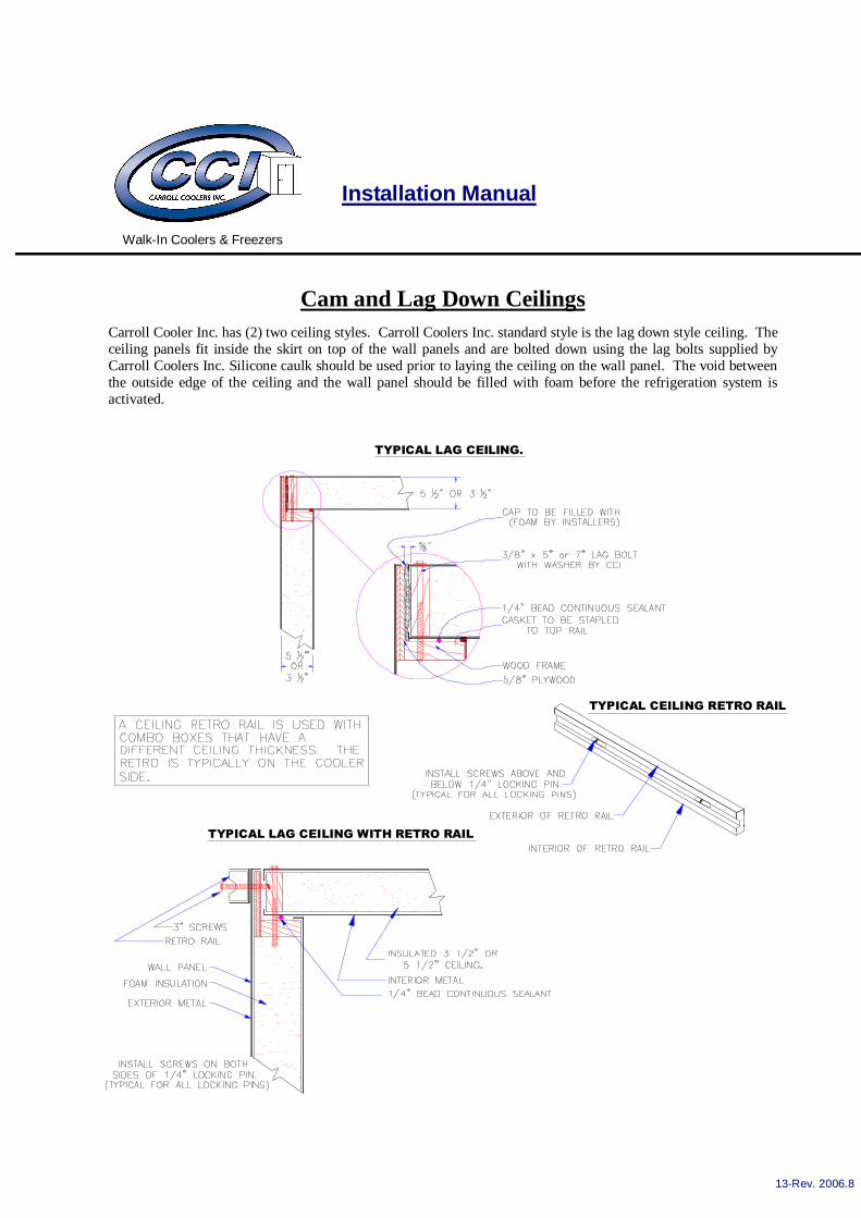
Cam and Lag Down Ceilings Carroll Cooler Inc. has (2) two ceiling styles. Carroll Coolers Inc. standard style is the lag down style ceiling. The ceiling panels fit inside the skirt on top of the wall panels and are bolted down using the lag bolts supplied by Carroll Coolers Inc. Silicone caulk should be used prior to laying the ceiling on the wall panel. The void between the outside edge of the ceiling and the wall panel should be filled with foam before the refrigeration system is activated.
���������������������� � �� ���
��������������� � �� ���
������������������!

Installation Manual
Walk-In Coolers & Freezers
14-Rev. 2006.8
Ceilings Continued
The cam lock style ceiling is available as an option. In this case the ceiling panels are placed on top of the wall panels and the cams are locked in place in the same manner as the wall panels. The cam down ceiling should be properly caulked prior to activating the cam lock from inside the walk-in. (Freezer application only)
�����������������������
��������������������������� � �� ���

Installation Manual
Walk-In Coolers & Freezers
15-Rev. 2006.8
Ceiling Support Details There are various methods to support a ceiling . The most common methods are shown in the following drawings.
When a rough (buck) opening is required in a walk-in wall for cooler or freezer glass doors, it is necessary to support the ceiling panels above the glass door frame area. This support is done by use of ceiling hangers and suspension materials (see detail below). The ceiling hanger is fastened to the female rail of the panel by three 2” sheet rock screws before installing the ceiling panel. After panel is installed, the suspension material is attached to the overhead building structure and to hanger bracket. The length of suspension material is adjusted until tension of material is observed to relieve weight on door frame area and inside height of walk-in is correct.
Exterior Ceiling Support Details
Interior Ceiling Support Details
(Supporting material such as cable or threaded rod supplied by others)

Installation Manual
Walk-In Coolers & Freezers
16-Rev. 2006.8
Header and Sill Details
����������� �"������
���������� �����������
����� ������
����� ������

Installation Manual
Walk-In Coolers & Freezers
17-Rev. 2006.8
Typical Cooler Door Electrical Typical Freezer Door Electrical
Electrical Information
Door Size
Light
Door Heater
Optional
Vision Port
Pressure Relief Port
(Freezer Only)
Optional Digital
Thermometer 30" Wide 100 Watt Max. 1.06 Amps .6 Amps .2 Amps 12 Volts 34" Wide 100 Watt Max. 1.06 Amps .6 Amps .2 Amps 12 Volts 36" Wide 100 Watt Max. 1.06 Amps .6 Amps .2 Amps 12 Volts 42" Wide 100 Watt Max. 1.17 Amps .6 Amps .2 Amps 12 Volts 48" Wide 100 Watt Max. 1.26 Amps .6 Amps .2 Amps 12 Volts 54" Wide 100 Watt Max. 1.35 Amps .6 Amps .2 Amps 12 Volts 60" Wide 100 Watt Max. 1.43 Amps .6 Amps .2 Amps 12 Volts 30"X36" N/A .52 Amps N/A .2 Amps 12 Volts 24"X34" N/A .48 Amps N/A .2 Amps 12 Volts 24"X63" N/A .70 Amps N/A .2 Amps 12 Volts
All Doors are 115/60/1. The light switch is rated for 15 amps.

Installation Manual
Walk-In Coolers & Freezers
18-Rev. 2006.8
Dial Thermometer Calibration
1. Wipe up spills with warm water and mild soap. (never use caustic or abrasive cleaners) 2. To clean up dirt or fingerprints from wall surfaces, use the same procedures as above. 3. Clean door gaskets regularly. 4. Check and lubricate door hinges using petroleum jelly as needed. 5. If any hardware becomes loose, or malfunctions contact CCI for information or replacement. 6. The top of the walk-in is not a storage area. Damage caused by the storage of anything on the top of the walk-in is not covered by warranty.
Maintenance
Your dial thermometer is an accurate thermometer that conforms to NSF standards. This standard states that the thermometer must be accurate within plus or minus 2 degrees Fahrenheit. The thermometer should be checked after installation because of the possible rough handling during shipment. To adjust the thermometer you should fill a 32 ounce cup with ice and cold water. Place the thermometer probe in the cup for approximately 1 minute for the temperature reading. The temperature should read 32 degrees Fahrenheit, plus or minus 2 degrees Fahrenheit. If the thermometer needs adjustment remove lens assembly and place index finger at left side of the wide end of pointer, close to the hub. Insert small screwdriver in pointer slot and turn slowly clockwise for lower temperature and counter-clockwise for a higher setting. Adjust to proper setting and replace lens assembly. If the needle has fallen off during shipment, remove lens assembly, put needle on stem with pointer down (6 o’clock). Gently press needle on stem. Test and calibrate using the procedure described above. Replace lens assembly.
Final Inspection 1. All Locks are engaged and wrench ports closed with cap buttons. 2. Entrance door operates smoothly and seals properly. 3. Thermometer has been adjusted to proper temperature. 4. All excess sealant has been removed and residue cleaned up with proper cleaner.

Installation Manual
Walk-In Coolers & Freezers
19-Rev. 2006.8
One (1) Year Warranty Carroll Coolers, Inc. warrants to the original purchaser every walk-in cooler or freezer to be free from defects in material and factory workmanship under normal use and service for a period of one (1) year (not to exceed one (1) year and three (3) months from original shipment date). CCI will repair or replace, not including freight charges, the refrigeration, mechanical and electrical component of any CCI walk-in cooler or freezer that becomes defective. Any defective parts to be repaired or replaced must be returned to the destination designated by CCI, transportation charges prepaid, and they must be properly packaged and identified with a return material tag. This return material tag must be obtained from CCI. The serial and model number of the part and the date of original installation of the CCI walk-in must be given. After thorough examination of the defective parts, the decision of the CCI sales department shall be final. CCI will not assume any responsibility for any expenses (including labor) incurred in the field incidental to the repair of and replacement of equipment covered by this warranty. Additional Four (4) year Compressor Warranty At an additional charge, CCI warrants to the original purchaser the refrigeration compressor for a period of four (4) years beginning after one (1) year from original shipment. The four-year warranty, when purchased covers the replacement of the compressor only. The refrigerant and labor is expressly not included in this warranty. Contact factory for proper replacement procedures.
Ten (10) Year Limited Panel Warranty CCI warrants to the original purchaser, the foamed-in-place polyurethane panels manufactured and sold by them, to be free from defects in material and workmanship under normal use and service for a period of ten (10) years from the date of original installation by an authorized representative. This warranty is void if the panels have been moved from the original site and reinstalled. General Provisions Applicable to all Walk-In Warranties CCI shall not be liable for any breach of any express warranty set forth above unless CCI is informed immediately upon the discovery of defective part (s). The warranties described above are not transferable and shall operate only in favor of the original buyer/user. These warranties shall not apply to any goods, or any part thereof, which may have been subject to any damage in transit, accident, negligence, abuse or misuse, unauthorized alteration or repair, acts of nature or failure to follow any of CCI’s manuals or instructions, if in CCI’s sole judgment, such act, omission or event has detrimentally affected the physical
condition, use or operating qualities of the product. CCI MAKES NO WARRANTY, EXPRESS OR IMPLIED, BY REASON OF LAW, STATURE OR OT HERWISE, INCLUDING ANY IMPLIED WARRANTY OF MERCHANTABILITY O R FITNESS FOR A PARTICULAR USE OR PURPOSE, AND IMPLIE D WARRANTIES ARE HEREBY DISCLAIMED. CCI SHALL NOT BE LIABLE FOR LOSS OF GOODS, MERCHANDISE OR OTHER PROPERTY, OR LOSS OF PROFITS, RESULTING FROM PRODUCT DEFECTS. IN NO EVENT SHALL CCI’S LIABILITY UNDER ANY CIRCUMSTANCES FOR A NY BREACH OF CONTRACT OR FOR ANY OTHER CLAIM BY BUYER AGAINST CCI EXCEED THE CONTRACT PRICE OF THE GOODS SOLD HEREUNDER WITH RESPECT TO WHICH SUCH CLAIM ARISES .

Installation Manual
Walk-In Coolers & Freezers
20-Rev. 2006.8
NOTES