Embed Size (px)
Citation preview

Web Address: www.oldcastlebe.comPhone: 1-866-OLDCASTLE (653-2278)
Note: Installation and Glazing Manuals are product specific. FOR REVIEW ONLY!
MAY 2013
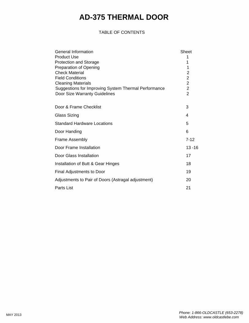
General Information SheetProduct Use 1Protection and Storage 1
Check Material 2Field Conditions 2Cleaning Materials 2Suggestions for Improving System Thermal Performance 2
Glass Sizing 4
TABLE OF CONTENTS
Preparation of Opening 1
Standard Hardware Locations 5
Door Handing 6
Frame Assembly 7-12
Door Frame Installation 13 -16
Door Glass Installation 17
Installation of Butt & Gear Hinges 18
Final Adjustments to Door 19
Phone: 1-866-OLDCASTLE (653-2278)Web Address: www.oldcastlebe.com
MAY 2013
AD-375 THERMAL DOOR
Adjustments to Pair of Doors (Astragal adjustment) 20
Door Size Warranty Guidelines 2
Door & Frame Checklist 3
Parts List 21
The AD-375 Thermal Doors are intended for installation by glazing professionals with appropriate experience.Subcontractors without experience should employ a qualified person to provide field instruction and projectmanagement.Oldcastle BuildingEnvelope does not control the application or selection of its product configurations,sealant or glazing material and assumes no responsibility thereof. It is the responsibility of the owner,architect and installer to make these selections in strict compliance with applicable laws and building codes.Consult sealant manufacturer for review and recommendation of sealant application. Follow sealantmanufacturer's recommendations and literature for proper installation.The air and water performance of the AD-375 Thermal Door system is directly related to the completenessand integrity of the installation process of both the seal installed at the horizontal to vertical connectionsthe glazing gasket installed at the interior side of the glass. To insure top performance of this system,particular attention should be given to the following procedures:
1. Surfaces to be sealed should be cleaned with isopropyl alcohol or solvent and dried asrecommended by sealant manufacturer to remove dirt and cutting oils. Sealant at horizontal tovertical connections should be a minimum 3/16" diameter bead on surfaces where horizontalabuts vertical per glazing instructions herein. No gaps should be visible in the sealant. Exposedsurfaces should be cleaned after installing the horizontal. Inspect joint for complete sealantcontact, especially where the horizontal meets the face of the vertical member. Repair joint asrequired.
2. The glazing gasket should be installed so as to avoid stretching, buckles or tears.Corners must be cut to form a tight joint. To avoid damage to gasket and corner jointsduring glazing, glass should be level and straight during installation.
Variations on the details shown are inevitable and are not the responsibility of Oldcastle BuildingEnvelopewhen drawn by others. Oldcastle BuildingEnvelope strongly encourages its customers to use itsEngineering department for calculations and shop drawings.
Consult glass manufacturer for correct setting block location and length for glass sizes in excess of 40 sq.ft.
Handle all material carefully. Do not drop from the truck. Stack with adequate separation so the material willnot rub together. Store material off the ground, protecting against the elements and other constructionhazards by using a well ventilated covering. Remove material from package if wet or located in a damp area.For further guidelines consult AAMA publication "Care and Handling of Architectural Aluminum From Shop toSite."
TM
TM
TM
Prior to installation of a door and frame, it is important to consider your surrounding construction.Is the opening large enough to handle the door and frame that was ordered?Allow for at least 1/4" shim space all around the frame.Are there any obstructions present within the opening?Is there sufficient structure to anchor the frame?Is the support in the proper location?What is the sill condition?
Is there a ledge?Is there enough space to get anchorage into the floor slab?Is the floor slab sloping away from the door so that it may operate properly?
Be sure the slab is level from side to side at door area.Threshold will be standard 4 1/2" wide, 1/2" tall sloped from back to front.
If there is a problem with location of opening or slab level, please contact your general contractor, in writingrequesting a correction. DO NOT begin installation until problems are resolved.
GENERAL INFORMATION
PRODUCT USE
PROTECTION AND STORAGE
PREPARATION OF OPENING
Phone: 1-866-OLDCASTLE (653-2278)Web Address: www.oldcastlebe.com
1MAY 2013
AD-375 THERMAL DOOR
Check glass dimensions for overall size as well as thickness. Oldcastle BuildingEnvelope cannot be heldresponsible for gaskets that are not water tight due to extreme glass tolerances. The AD-375 Thermal Doorwall system is designed to accommodate glass or panels measuring 1" or 1-9/16" in thickness (+/- 1/32").Check all material upon arrival at job site for quality and to determine any shipping damage.
Using the contract documents, completely check the surrounding conditions that will receive your materials.Notify the general contractor by letter of any discrepancies before proceeding with the work. Failure to do soconstitutes acceptance of work by other trades.
Check shop drawings, installation instructions, architectural drawings and shipping lists to become familiarwith the project. The shop drawings take precedence and include specific details for the project. Theinstallation instructions are of a general nature and cover the most common conditions. Due to varying jobconditions all sealant must be approved by the sealant manufacturer to insure it will perform per theconditions shown on the instructions and shop drawings. The sealant must be compatible with all surfaces inwhich adhesion is required, including other sealant surfaces. Use primers where directed by sealantmanufacturer. Properly store sealant at the recommended temperatures and check sealant for remainder ofshelf life before using.
All material to be installed must be plumb, level and true. Aluminum to be placed in direct contact withmasonry or incompatible material should be isolated with a heavy coat of zinc chromate, bituminous paint ornon-metallic material.After sealant is set and a representative amount of the wall has been glazed (250 sq.ft. or more), perform awater hose test in accordance with AAMA 501.2 specifications to check installation. On large projects thehose test should be repeated during the glazing operation.
Cement, plaster terrazzo, alkaline and acid based materials used to clean masonry are very harmful tofinishes. Any residue should be removed with water and mild soap immediately or permanent staining willoccur. A spot test is recommended before any cleaning agent is used. Refer to the Architectural FinishGuide in the Detail Catalog.
To maintain or improve your wall installation the following items should be considered.A. Blinds or drapes prevent warm air from adequately flowing over the window surface.B. Warm air ventilators too far from the window will not adequately wash the window with air to
prevent condensation.C. In extreme conditions the fan of the heating system should not cycle on and off, but should run
continuously.D. Some heating systems have a water injection feature that can raise humidity levels. The higher
the humidity levels the more likely condensation or frost will form. Raising the temperatures andreducing humidity will usually solve the problem.
E. On rare occasions an extremely cold storm may cause frost to appear on the glass framing. Aspace heater and electric fan blowing along the plane of the window wall can reduce or eliminatethis temporary condition.
TM
The following are Oldcastle BuildingEnvelope standard warranty guidelines and recommendations for special size doors (all sizes are maximums):
1. Doors with 1" glass = 4'-0" x 9'-0" / Minimum 1 1/2 pair of butt hinges
GENERAL INFORMATION
CHECK MATERIAL
FIELD CONDITIONS
CLEANING MATERIALS
SUGGESTIONS FOR IMPROVING SYSTEM THERMAL PERFORMANCE
DOOR SIZE WARRANTY GUIDELINES
Phone: 1-866-OLDCASTLE (653-2278)Web Address: www.oldcastlebe.com
2MAY 2013
AD-375 THERMAL DOOR
TM
Check doors upon arrival to insure top and bottom seals are in place and not damaged in shipping. (ref.pg.3)
DOOR & FRAME CHECKLIST
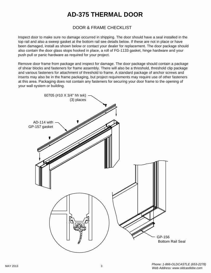
Inspect door to make sure no damage occurred in shipping. The door should have a seal installed in thetop rail and also a sweep gasket at the bottom rail see details below. If these are not in place or havebeen damaged, install as shown below or contact your dealer for replacement. The door package shouldalso contain the door glass stops hooked in place, a roll of FG-1133 gasket, hinge hardware and yourpush pull or panic hardware as required for your project.
Remove door frame from package and inspect for damage. The door package should contain a packageof shear blocks and fasteners for frame assembly. There will also be a threshold, threshold clip packageand various fasteners for attachment of threshold to frame. A standard package of anchor screws andinserts may also be in the frame packaging, but project requirements may require use of other fastenersat this area. Packaging does not contain any fasteners for securing your door frame to the opening ofyour wall system or building.
Phone: 1-866-OLDCASTLE (653-2278)Web Address: www.oldcastlebe.com
3MAY 2013
AD-375 THERMAL DOOR
AD-114 withGP-157 gasket
60705 (#10 X 3/4" hh tek)(3) places
GP-156 Bottom Rail Seal
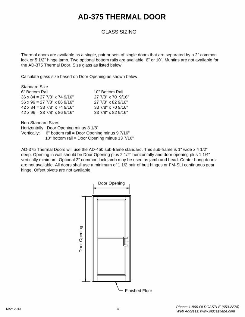
Thermal doors are available as a single, pair or sets of single doors that are separated by a 2" commonlock or 5 1/2" hinge jamb. Two optional bottom rails are available; 6" or 10". Muntins are not available forthe AD-375 Thermal Door. Size glass as listed below.
Calculate glass size based on Door Opening as shown below.
Standard Size6" Bottom Rail 10" Bottom Rail36 x 84 = 27 7/8" x 74 9/16" 27 7/8" x 70 9/16"36 x 96 = 27 7/8" x 86 9/16" 27 7/8" x 82 9/16"42 x 84 = 33 7/8" x 74 9/16" 33 7/8" x 70 9/16"42 x 96 = 33 7/8" x 86 9/16" 33 7/8" x 82 9/16"
Non-Standard Sizes:Horizontally: Door Opening minus 8 1/8"Vertically: 6" bottom rail = Door Opening minus 9 7/16" 10" bottom rail = Door Opening minus 13 7/16"
AD-375 Thermal Doors will use the AD-450 sub-frame standard. This sub-frame is 1" wide x 4 1/2"deep. Opening in wall should be Door Opening plus 2 1/2" horizontally and door opening plus 1 1/4"vertically minimum. Optional 2" common lock jamb may be used as jamb and head. Center hung doorsare not available. All doors shall use a minimum of 1 1/2 pair of butt hinges or FM-SLI continuous gearhinge, Offset pivots are not available.
GLASS SIZING
Doo
r Ope
ning
Door Opening
Finished Floor
Phone: 1-866-OLDCASTLE (653-2278)Web Address: www.oldcastlebe.com
4MAY 2013
AD-375 THERMAL DOOR
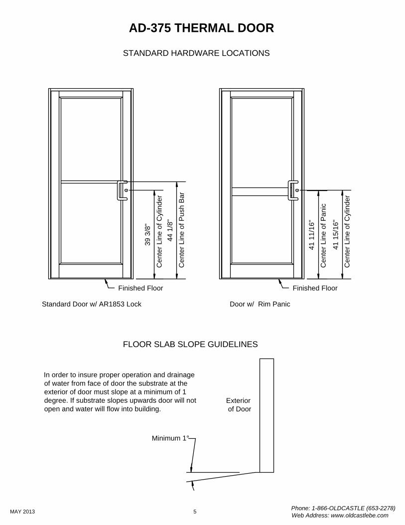
44 1
/8"
39 3
/8"
41 1
5/16
"
41 1
1/16
"
Cen
ter L
ine
of P
anic
Cen
ter L
ine
of C
ylin
der
Cen
ter L
ine
of P
ush
Bar
Cen
ter L
ine
of C
ylin
der
Standard Door w/ AR1853 Lock Door w/ Rim Panic
Exterior of Door
Minimum 1°
In order to insure proper operation and drainageof water from face of door the substrate at theexterior of door must slope at a minimum of 1degree. If substrate slopes upwards door will notopen and water will flow into building.
Finished FloorFinished Floor
STANDARD HARDWARE LOCATIONS
FLOOR SLAB SLOPE GUIDELINES
Phone: 1-866-OLDCASTLE (653-2278)Web Address: www.oldcastlebe.com
5MAY 2013
AD-375 THERMAL DOOR
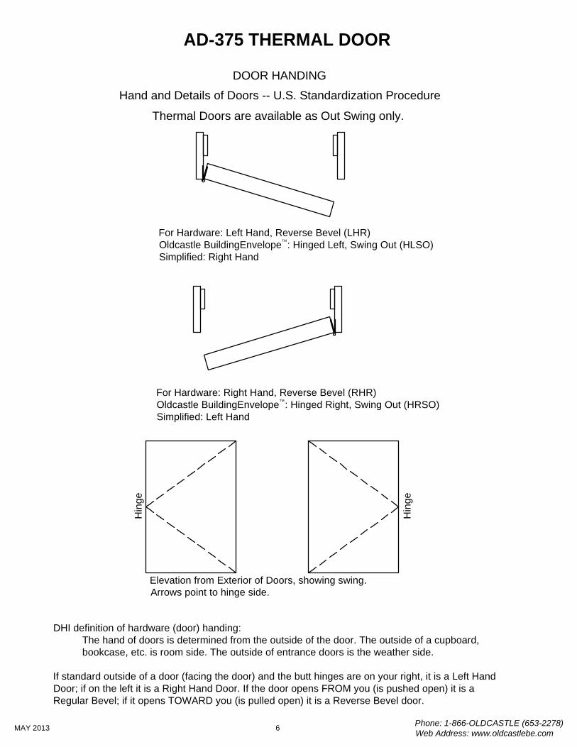
Hand and Details of Doors -- U.S. Standardization Procedure
Thermal Doors are available as Out Swing only.
For Hardware: Left Hand, Reverse Bevel (LHR)Oldcastle BuildingEnvelope : Hinged Left, Swing Out (HLSO)Simplified: Right Hand
For Hardware: Right Hand, Reverse Bevel (RHR)Oldcastle BuildingEnvelope : Hinged Right, Swing Out (HRSO)Simplified: Left Hand
Hin
ge
Hin
ge
Elevation from Exterior of Doors, showing swing.Arrows point to hinge side.
DOOR HANDING
Phone: 1-866-OLDCASTLE (653-2278)Web Address: www.oldcastlebe.com
6MAY 2013
AD-375 THERMAL DOOR
TM
TM
DHI definition of hardware (door) handing: The hand of doors is determined from the outside of the door. The outside of a cupboard, bookcase, etc. is room side. The outside of entrance doors is the weather side.
If standard outside of a door (facing the door) and the butt hinges are on your right, it is a Left HandDoor; if on the left it is a Right Hand Door. If the door opens FROM you (is pushed open) it is aRegular Bevel; if it opens TOWARD you (is pulled open) it is a Reverse Bevel door.
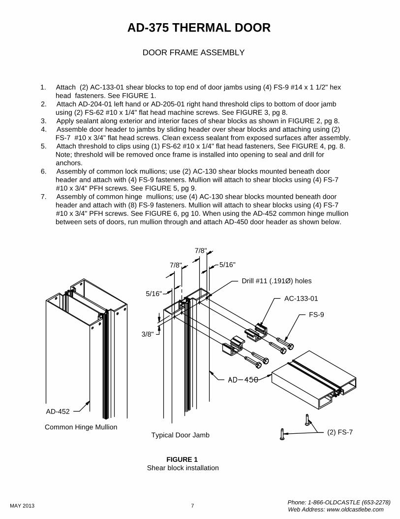
DOOR FRAME ASSEMBLY
1. Attach (2) AC-133-01 shear blocks to top end of door jambs using (4) FS-9 #14 x 1 1/2" hexhead fasteners. See FIGURE 1.
2. Attach AD-204-01 left hand or AD-205-01 right hand threshold clips to bottom of door jambusing (2) FS-62 #10 x 1/4" flat head machine screws. See FIGURE 3, pg 8.
3. Apply sealant along exterior and interior faces of shear blocks as shown in FIGURE 2, pg 8.4. Assemble door header to jambs by sliding header over shear blocks and attaching using (2)
FS-7 #10 x 3/4" flat head screws. Clean excess sealant from exposed surfaces after assembly.5. Attach threshold to clips using (1) FS-62 #10 x 1/4" flat head fasteners, See FIGURE 4, pg. 8.
Note; threshold will be removed once frame is installed into opening to seal and drill foranchors.
6. Assembly of common lock mullions; use (2) AC-130 shear blocks mounted beneath doorheader and attach with (4) FS-9 fasteners. Mullion will attach to shear blocks using (4) FS-7#10 x 3/4" PFH screws. See FIGURE 5, pg 9.
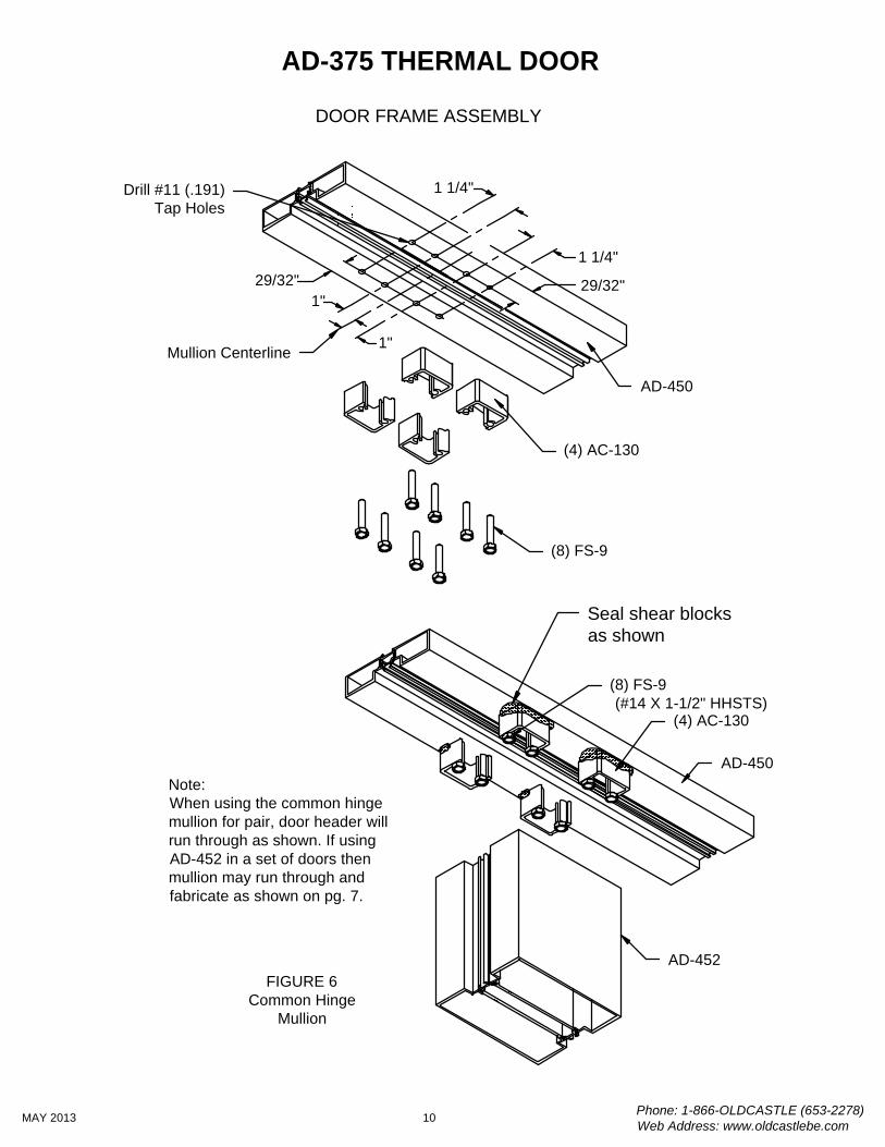
7. Assembly of common hinge mullions; use (4) AC-130 shear blocks mounted beneath doorheader and attach with (8) FS-9 fasteners. Mullion will attach to shear blocks using (4) FS-7#10 x 3/4" PFH screws. See FIGURE 6, pg 10. When using the AD-452 common hinge mullionbetween sets of doors, run mullion through and attach AD-450 door header as shown below.
FIGURE 1Shear block installation
AC-133-01
FS-9
3/8"
5/16"
7/8" 5/16"
7/8"
Drill #11 (.191Ø) holes
AD-452
Common Hinge MullionTypical Door Jamb
Phone: 1-866-OLDCASTLE (653-2278)Web Address: www.oldcastlebe.com
7MAY 2013
AD-375 THERMAL DOOR
(2) FS-7
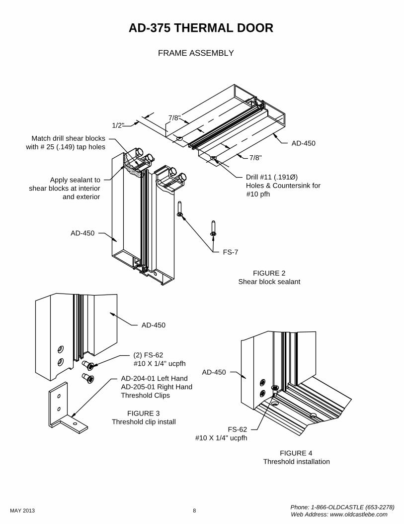
FIGURE 2Shear block sealant
Apply sealant toshear blocks at interior
and exterior
FS-7
1/2"7/8"
7/8"
Drill #11 (.191Ø)Holes & Countersink for#10 pfh
(2) FS-62#10 X 1/4" ucpfh
AD-204-01 Left HandAD-205-01 Right HandThreshold Clips
FIGURE 3Threshold clip install
FIGURE 4Threshold installation
FS-62#10 X 1/4" ucpfh
FRAME ASSEMBLY
Match drill shear blockswith # 25 (.149) tap holes
Phone: 1-866-OLDCASTLE (653-2278)Web Address: www.oldcastlebe.com
8MAY 2013
AD-375 THERMAL DOOR
AD-450
AD-450
AD-450
AD-450
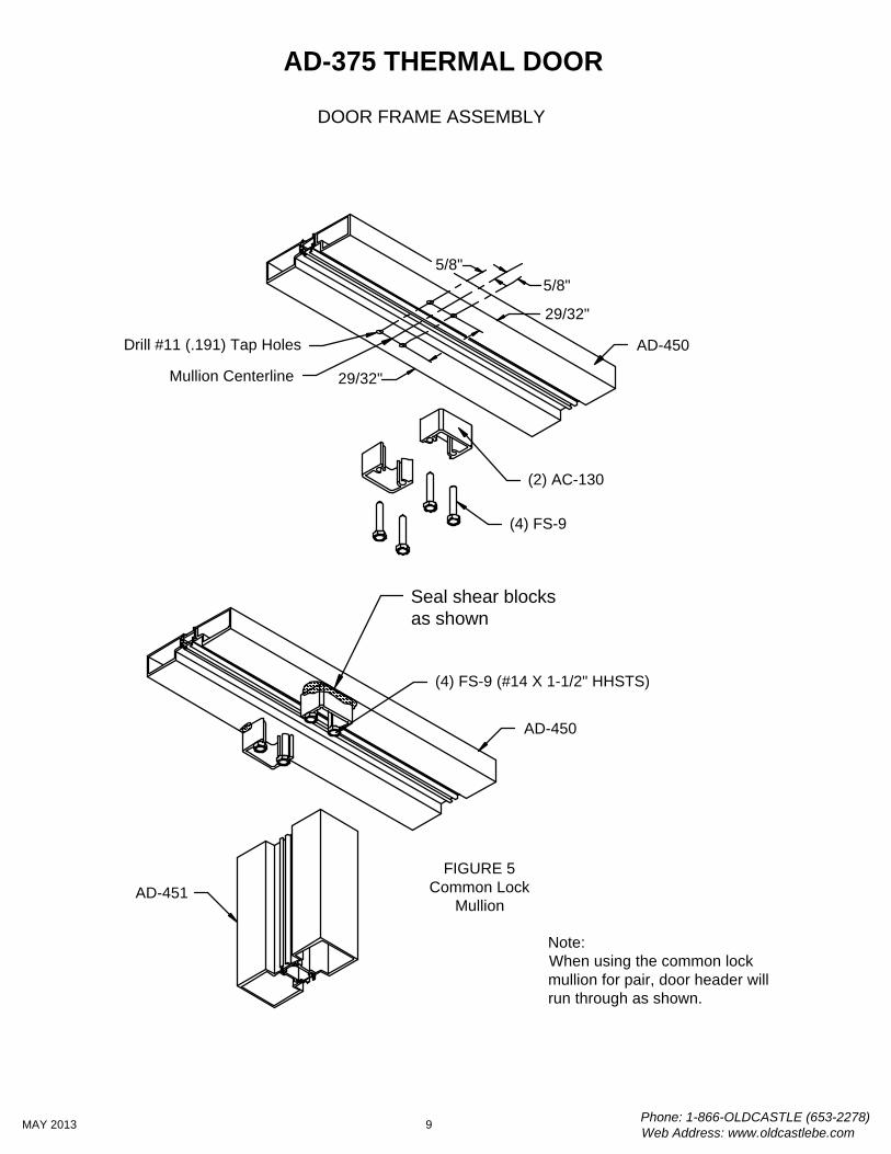
DOOR FRAME ASSEMBLY
Seal shear blocksas shown
(4) FS-9 (#14 X 1-1/2" HHSTS)
(2) AC-130
FIGURE 5Common Lock
Mullion
Phone: 1-866-OLDCASTLE (653-2278)Web Address: www.oldcastlebe.com
9MAY 2013
AD-375 THERMAL DOOR
5/8"5/8"
Mullion Centerline
29/32"
29/32"
Drill #11 (.191) Tap Holes
AD-451
AD-450
(4) FS-9
AD-450
Note:When using the common lockmullion for pair, door header willrun through as shown.
DOOR FRAME ASSEMBLY
(4) AC-130
(8) FS-9 (#14 X 1-1/2" HHSTS)
Seal shear blocksas shown
FIGURE 6Common Hinge
Mullion
Note:When using the common hingemullion for pair, door header willrun through as shown. If usingAD-452 in a set of doors thenmullion may run through andfabricate as shown on pg. 7.
Phone: 1-866-OLDCASTLE (653-2278)Web Address: www.oldcastlebe.com
10MAY 2013
AD-375 THERMAL DOOR
AD-452
(4) AC-130
1 1/4"
1"
Mullion Centerline
29/32"29/32"
Drill #11 (.191) Tap Holes
1 1/4"
1"
(8) FS-9
AD-450
AD-450
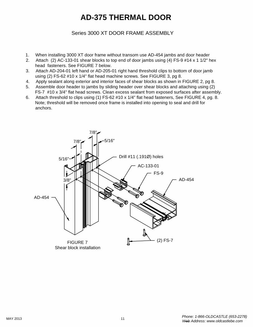
Series 3000 XT DOOR FRAME ASSEMBLY
1. When installing 3000 XT door frame without transom use AD-454 jambs and door header2. Attach (2) AC-133-01 shear blocks to top end of door jambs using (4) FS-9 #14 x 1 1/2" hex
head fasteners. See FIGURE 7 below.3. Attach AD-204-01 left hand or AD-205-01 right hand threshold clips to bottom of door jamb
using (2) FS-62 #10 x 1/4" flat head machine screws. See FIGURE 3, pg 8.4. Apply sealant along exterior and interior faces of shear blocks as shown in FIGURE 2, pg 8.5. Assemble door header to jambs by sliding header over shear blocks and attaching using (2)
FS-7 #10 x 3/4" flat head screws. Clean excess sealant from exposed surfaces after assembly.6. Attach threshold to clips using (1) FS-62 #10 x 1/4" flat head fasteners, See FIGURE 4, pg. 8.
Note; threshold will be removed once frame is installed into opening to seal and drill foranchors.
FIGURE 7Shear block installation
AC-133-01
FS-93/8"
5/16"
7/8" 5/16"
7/8"
Drill #11 (.191Ø) holes
Phone: 1-866-OLDCASTLE (653-2278)Web Address: www.oldcastlebe.com
11MAY 2013
AD-375 THERMAL DOOR
(2) FS-7
AD-454
AD-454
Series 3000 XT DOOR FRAME ASSEMBLY
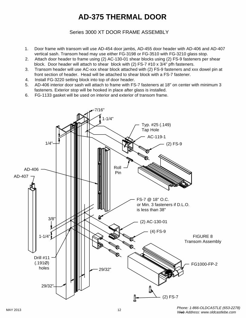
1. Door frame with transom will use AD-454 door jambs, AD-455 door header with AD-406 and AD-407vertical sash. Transom head may use either FG-3198 or FG-3510 with FG-3210 glass stop.
2. Attach door header to frame using (2) AC-130-01 shear blocks using (2) FS-9 fasteners per shearblock. Door header will attach to shear block with (2) FS-7 #10 x 3/4" pfh fasteners.
3. Transom header will use AC-xxx shear block attached with (2) FS-9 fasteners and xxx dowel pin atfront section of header. Head will be attached to shear block with a FS-7 fastener.
4. Install FG-3220 setting block into top of door header.5. AD-406 interior door sash will attach to frame with FS-7 fasteners at 18" on center with minimum 3
fasteners. Exterior stop will be hooked in place after glass is installed.6. FG-1133 gasket will be used on interior and exterior of transom frame.
FIGURE 8Transom Assembly
3/8"
Drill #11(.191Ø)
holes
Phone: 1-866-OLDCASTLE (653-2278)Web Address: www.oldcastlebe.com
12MAY 2013
AD-375 THERMAL DOOR
(2) FS-7
FS-7 @ 18" O.C.or Min. 3 fasteners if D.L.O.is less than 38"
(4) FS-9
(2) FS-9
RollPin
AC-119-1
(2) AC-130-01
AD-406AD-407
Typ. #25 (.149)Tap Hole
FG1000-FP-2
1/4"
1-1/4"
29/32"
7/16"
29/32"
1-1/4"

DOOR FRAME INSTALLATION
1. Door frame shall be completely assembled, including threshold; with all joints neatly aligned andtight. See pages 7 thru 12 for assembly guidelines.
2. Door frame shall be installed square and plumb. FIGURE 9 & 10, below.3. Level the door frame at the threshold at the highest point in the slab. It is preferable to not have
a high point in the slab. The door frame is designed to have the jambs run to the slab.4. Frame must be securely anchored in place. Solidly shim at all anchor points so as not to bow or
distort framing.5. Mark the concrete through the countersunk holes in the threshold and along front and back
edges of threshold. See FIGURE 11, pg 14.6. Remove threshold from opening. Use masonary bit to drill holes in slab for inserts or anchors.7. Run bead of sealant along front and back edges beneath threshold using lines marked along
front and back. See FIGURE 11, pg 14.8. Install threshold back into frame attaching to threshold clips at each end. Inject sealant into each
anchor hole and then install anchors into inserts or prepared holes.See FIGURE 12, pg 14.
FIGURE 9Measure diagonals to check squareness
P D196 GP10 4XXXP D19 5GP 103
A
B
FIGURE 10Use 4 ft level to check plumb at points A & B.
1/4" Min.
Shim
Phone: 1-866-OLDCASTLE (653-2278)Web Address: www.oldcastlebe.com
13MAY 2013
AD-375 THERMAL DOOR
AD-450
DOOR FRAME INSTALLATION
(1) FS-62#10-32 x 1/4" ucpfh
TH-61Threshold
Mark lines to locatefront and back ofthreshold
Apply bead of sealantfull length of thresholdbefore installing andanchoring.
Fill cavity at endsof threshold with
sealant afterinstallation
FIGURE 11Threshold sealant Mark hole locations for
anchors through holes inthreshold. Drill for specifiedanchor bolts per engineersspecifications.
Seal anchor locations beforeinstalling anchor bolts.
Flat head anchor boltper engineer's specifications
FIGURE 12Threshold sealant
Phone: 1-866-OLDCASTLE (653-2278)Web Address: www.oldcastlebe.com
14MAY 2013
AD-375 THERMAL DOOR
DOOR FRAME INSTALLATION
1. Install GP-155 mid-seal gasket into race in thermal composite strut. Use light soapywater or window cleaner to assist in installation of gasket. Cut gasket door opening plus1/8" per foot. Note: Gasket must be installed prior to door stops.
2. Clean areas of gasket with isopropyl alcohol where sealant will be required.3. The mid-seal gasket at the door header must be notched on each end as shown in
FIGURE 12. Vertical gasket cut square typical.4. Joint at door header to jamb at gasket must be sealed per FIGURE 13.5. The GP-155 Gasket must also be sealed at threshold per FIGURE 15 & 16, pg 16.6. Install AD-403 door stop. See FIGURE 15, pg.16.
6.1. Install SC-1 spring clips at pre-fabricated locations using FS-15 drive rivets.6.2. Apply bead of sealant along edge of door jamb at inner face as shown in FIGURE
13, pg. 14. Sealant applied to vertical door stops only.6.3. Snap AD-403 door stop onto clips. Tool sealant along front edge of stop and
remove excess as needed.6.4. Seal around base of door stop as shown in FIGURE 16, pg 16.6.5. Seal between door jamb stop and threshold bulb gaskets. See FIGURE 16, pg.16.
5/16" FIGURE 14GP-155 notch at header
FIGURE 13GP-155 Header Seal
Notch ends of GP-155 gasketat door header
Seal corner of GP-155 gasketand between gooseneckleg of gasket
Phone: 1-866-OLDCASTLE (653-2278)Web Address: www.oldcastlebe.com
15MAY 2013
AD-375 THERMAL DOOR
DOOR FRAME INSTALLATION
GP-155 GasketSeal at threshold
Bed Door Stopin Sealant alongfront leg.
Bed threshold in sealantand seal at ends to door
jamb, door stop andGP-155 gasket
FS-15 Drive Rivet
SC-1 Clip
FIGURE 15Door stop install
& gasket seal
FIGURE 16GP-155 threshold seal
Seal between jamb &threshold bulb gaskets
Phone: 1-866-OLDCASTLE (653-2278)Web Address: www.oldcastlebe.com
16MAY 2013
AD-375 THERMAL DOOR
AD-403 Door Stop
Door Stop
Seal bottom of doorstop to threshold
DOOR GLASS INSTALLATION
Glass setting blocks are installed in their proper positions at the factory. Glazing prior to installation ispossible (step 1). If the decision is made to glaze after door is installed, skip step 1.
1. Lay door flat across two saw horses (easiest) or on protected floor (care must be taken not todamage finish on door.)
2. If glazing door after it is installed, lock door to prevent swinging.3. Remove glass stop from exterior of door.4. Install interior FG-1133 gasket into interior glass stops cutting horizontal gasket ends at angle to
form a tight joint in each corner. Gaskets should be cut length of stop plus 1/4" per foot extra to allowfor relaxing of gasket.
5. Turn glass jack at top rail counter-clockwise until it is in retracted position.6. Be sure that stops are in securely prior to installing glass.7. Place glass on the stops and against the setting blocks. If you are glazing the door in the installed
position, it is important to push glass firmly against the interior glass stops.8. Adjust for gaps at stiles.9. Once the glass is in the correct position, screw down the glass jack to press lightly against the top
of the glass.10. Install the exterior glass stops. Stops will hook into place. Verticals are installed first, followed by
horizontals.11. Once exterior stops are in place. Install FG-1133 gasket into opening. Use cut lengths established
in step #4 cutting gaskets to form tight corners.
FG-1133Gasket
FG-1133Gasket
AD-112GlassStop
Glass Jack
Phone: 1-866-OLDCASTLE (653-2278)Web Address: www.oldcastlebe.com
17MAY 2013
AD-375 THERMAL DOOR
INSTALLATION OF OFFSET HUNG DOOR ON BUTT HINGES
Back-up plates are installed in the door and the frame at the factory. Butt hinges should be installed onthe door using FS-22 (#12-24 x 1/2" UCPFH) fasteners. The door may or may not be glazed prior toinstallation of door.
1. Lift door upwards until butt hinges align with hinge cutout in frame.2. Block under door when hinge and cutout are aligned.3. Attach hinges to frame back-up plates using FS-22 fasteners (included). There is a slight
adjustment available if location of door prep and frame cut out is off slightly. Back off on screwsslightly and adjust door to proper position; then, tighten down screws.
4. Now that the door is hung, it is time for final adjustments and attachment of hardware. Note; if you have not pre-glazed the door; glaze the door before attachment of hardware or further adjustments.
INSTALLATION OF OFFSET HUNG DOOR ON GEAR HINGES
Door and frame will be pre-drilled for Pemko FM-SLI gear hinge. Gear hinge should be installed ontodoor using supplied fasteners. The door may or may not be glazed prior to installation.
1. Lift door upwards until hinges align with pre-drilled holes in frame.2. Block under door when holes in hinge and frame align.3. Attach gear hinges to frame using supplied fasteners.4. Now that the door is hung, it is time for final adjustments and attachment of hardware.
Note; if you have not pre-glazed the door; glaze the door before attachment of hardware or further adjustments.
NOTE:Thermal Doors are not available with Offset Pivots due to weight of door and weathering considerations.
Phone: 1-866-OLDCASTLE (653-2278)Web Address: www.oldcastlebe.com
18MAY 2013
AD-375 THERMAL DOOR
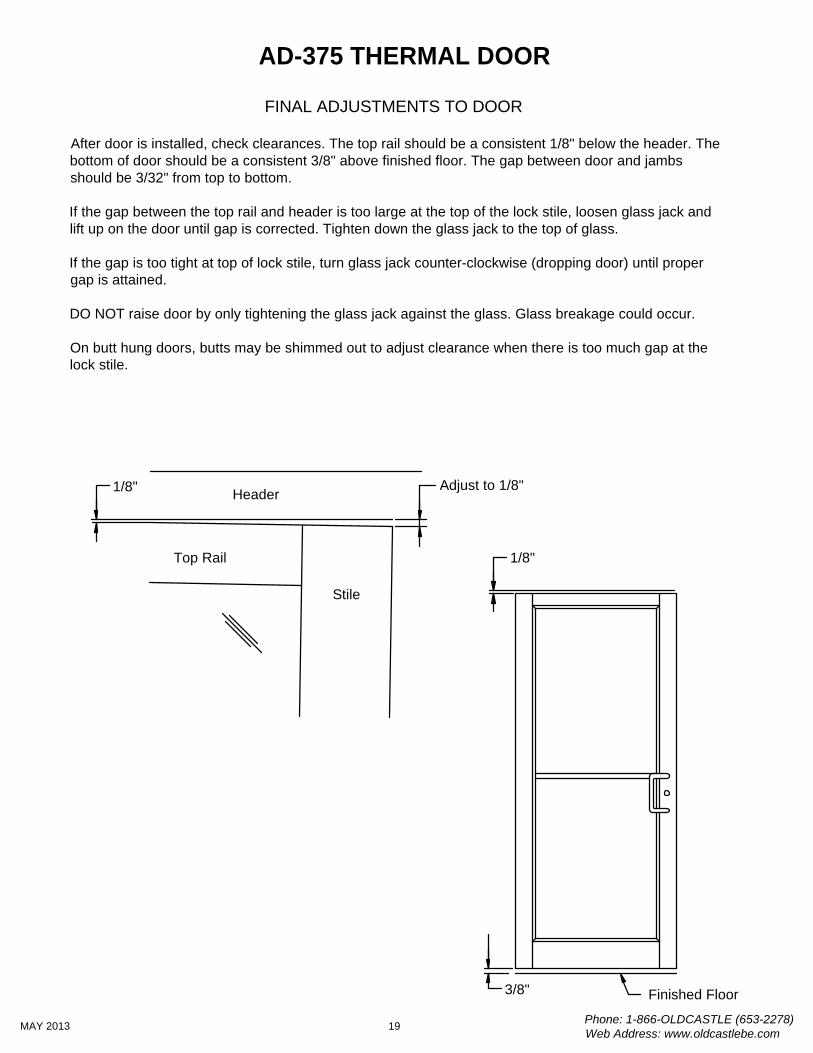
FINAL ADJUSTMENTS TO DOOR
After door is installed, check clearances. The top rail should be a consistent 1/8" below the header. Thebottom of door should be a consistent 3/8" above finished floor. The gap between door and jambsshould be 3/32" from top to bottom.
If the gap between the top rail and header is too large at the top of the lock stile, loosen glass jack andlift up on the door until gap is corrected. Tighten down the glass jack to the top of glass.
If the gap is too tight at top of lock stile, turn glass jack counter-clockwise (dropping door) until propergap is attained.
DO NOT raise door by only tightening the glass jack against the glass. Glass breakage could occur.
On butt hung doors, butts may be shimmed out to adjust clearance when there is too much gap at thelock stile.
Adjust to 1/8"
Stile
Top Rail
Header1/8"
1/8"
3/8"
Phone: 1-866-OLDCASTLE (653-2278)Web Address: www.oldcastlebe.com
19MAY 2013
AD-375 THERMAL DOOR
Finished Floor
INSTALLATION PAIRS OF DOORS
Located at the meeting stile of the pair of AD-375 thermal doors are threeadjustable astragals. The exterior astragal has a single strip of wool pileweathering. On the interior is located two astragals on opposing door stiles. Theseare a thermal plastic with bulb gasket. Each of these astragals may be adjustedindependently to create an air tight seal. See instructions below for properadjustment.
Adjust astragal so thatpiles lightly touch atcenter of opening
Adjust astragals on each doorequally so bulb gasket lightly touchesat center line of door full length.
Phone: 1-866-OLDCASTLE (653-2278)Web Address: www.oldcastlebe.com
20MAY 2013
AD-375 THERMAL DOOR
1. Adjust astragals on each door leaf so that the bulb gasket makes light contactwith inactive leaf bulb for full length of door at centerline.
2. Once astragals are adjusted, apply silicone sealant and tool flat at gap betweenastragal and door stile at threshold for 1" to close any gap at this connection.
3. Remove string from wool pile at exterior of door. Then adjust exterior astragal ofactive leaf so that the wool pile weather seals lightly touch at center of dooropening.
Seal gap at astragal to doorat threshold with silicone
for 1" after adjustment
1"
Seal gap at astragal to doorat threshold with silicone for 1" after adjustment
CL
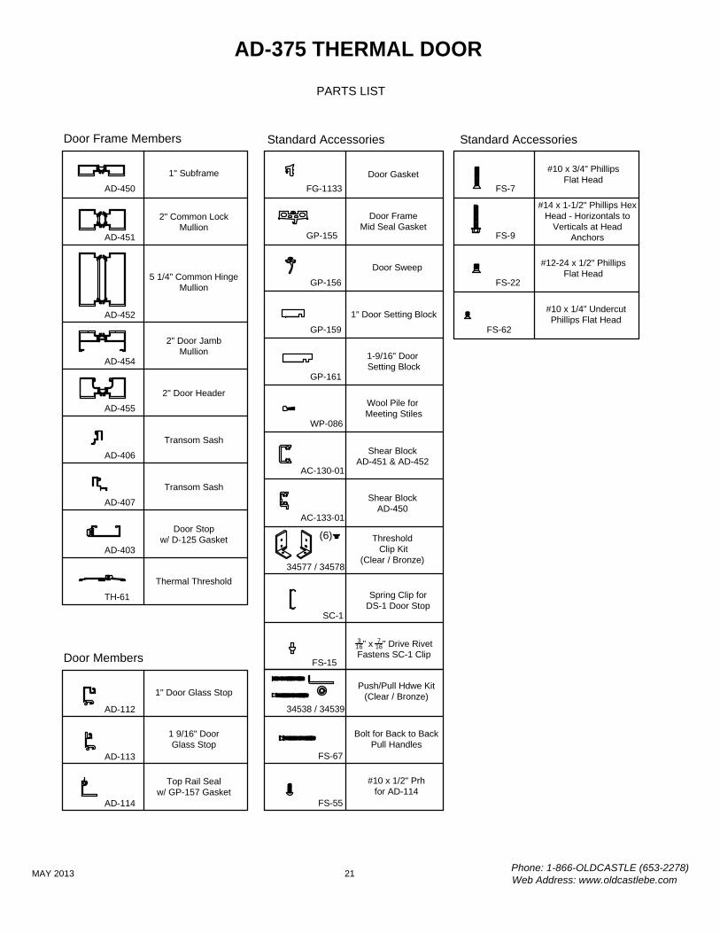
AD-450
AD-451
AD-452
1" Subframe
2" Common LockMullion
5 1/4" Common HingeMullion
Door Frame Members
Top Rail Sealw/ GP-157 Gasket
1" Door Glass Stop
1 9/16" DoorGlass Stop
AD-112
PARTS LIST
Door Members
AD-403
Door Stopw/ D-125 Gasket
AD-113
AD-114
TH-61
Thermal Threshold
Standard Accessories
#12-24 x 1/2" PhillipsFlat Head
FS-22
#14 x 1-1/2" Phillips HexHead - Horizontals to
Verticals at HeadAnchorsFS-9
#10 x 1/4" UndercutPhillips Flat Head
FS-62
#10 x 3/4" PhillipsFlat Head
FS-7
Phone: 1-866-OLDCASTLE (653-2278)Web Address: www.oldcastlebe.com
21MAY 2013
AD-375 THERMAL DOOR
Standard Accessories
34577 / 34578
AC-133-01
AC-130-01
Threshold Clip Kit
(Clear / Bronze)
Shear BlockAD-451 & AD-452
Shear BlockAD-450
GP-156
Door Sweep
GP-155
FG-1133Door Gasket
Door FrameMid Seal Gasket
GP-159
1" Door Setting Block
Spring Clip forDS-1 Door Stop
SC-1
316" x 7
16" Drive RivetFastens SC-1 Clip
FS-15
34538 / 34539
Push/Pull Hdwe Kit(Clear / Bronze)
WP-086
Wool Pile for Meeting Stiles
FS-67
Bolt for Back to BackPull Handles
(6)
FS-55
#10 x 1/2" Prhfor AD-114
GP-161
1-9/16" Door Setting BlockAD-454
2" Door JambMullion
AD-455
2" Door Header
AD-406
Transom Sash
AD-407
Transom Sash