Embed Size (px)
Citation preview
Waitaha Hydro Scheme
Morgan Gorge Intake
Preliminary Headworks Concept Contents 1 Introduction 2 Intake area 3 Weir 4 Intake Channel 5 Intake 6 Settling basin 7 Penstock intake 8 Flushing tunnel 9 Access Tunnel 10 Access Road. 11 Construction sequence 12 Operation Attachments
Figure 1a Concept Plan Figure 2 Intake Plan Figure 3 Section on weir Figure 4 Section on intake channel walls Figure 5c section on intake centreline
Ian McCahon Geotech Consulting Ltd Issue 3 1 August 2013
Waitaha Headworks Concept Page 2
Geotech Consulting Ltd 2818 – Issue 3 1 August 2013
1 Introduction This preliminary report outlines the concept design of the headworks for the proposed Waitaha Hydro-power scheme. The hydro scheme is to divert a flow of up to 23 m3/s from the Waitaha River, with the intake located at the upstream end of Morgan Gorge where the river discharges from the wide gravel bed across Kiwi Flats into a narrow rock walled slot gorge. From the headworks the scheme flow is taken through a penstock in a tunnel to a powerhouse well below Morgan Gorge to develop about 100m of head. The selection of the intake configuration is outlined in a previous intake options report. The proposed arrangement includes:
• A low weir across the river • An intake channel on the right bank which takes the river flow to the intake gate and
incorporates a channel and gate to sluice sediment past the intake • An intake gate housed at the start of a roofed culvert to convey the flow into the
tunnel portal • A second intake gate mounted in a shaft constructed in the natural rock face, to allow
water intake during high flood periods when the lower gate will be subject to high sediment load
• An underground sediment settling basin • Collection channel and penstock intake • Sediment flushing tunnel • Tunnel to access basin for maintenance • Tunnel to access portal and intake
The concept is shown in the attached drawings A-1 to A-5. 2 Intake area This site is immediately upstream of the entrance to Morgan Gorge. The site has some unusual features
• Morgan Gorge is a very steep sided slot gorge which appears in places to be as narrow as 6 – 7m, is 20m deep close to the top end, and deeper further downstream.
• Upstream of the gorge, the river flows over a wide gravel bed within Kiwi Flats. About 0.5km upstream of Morgan Gorge, the Whirling Waters tributary enters at a rock bluff on the true left, and the active river channel is restricted to about 100m width. Within a short distance downstream of this point, the river bed gradient increases and falls an estimated 10m into the gorge entrance.
• At the gorge entrance, the river channel extends through a platform of rock on each side, about 2 – 3m above normal water levels for about 20m upstream of the gorge proper.
• There is clear evidence in vegetation lines, fine sediment deposits and debris, that in large floods, the river ponds upstream of the gorge and this backwater effect extends up to about the Whirling Waters confluence. The flood depth at the gorge entrance is estimated to be 8 – 9m above the normal water level.
• The bed levels in the section of river upstream of the gorge are likely to controlled by the combination of the backwater effects of the flood levels and sediment load. During large floods, when the bulk of sediment transport occurs, the backwater will
Waitaha Headworks Concept Page 3
Geotech Consulting Ltd 2818 – Issue 3 1 August 2013
reduce the flow velocities and bedload is likely to be dropped by the flow, almost as a delta formation. Once the flood recedes, the river is then able to remobilize this material because of the steep gradient down the “delta” face. The bed levels in the 400m upstream of the gorge are therefore likely to fluctuate considerably during and following large floods.
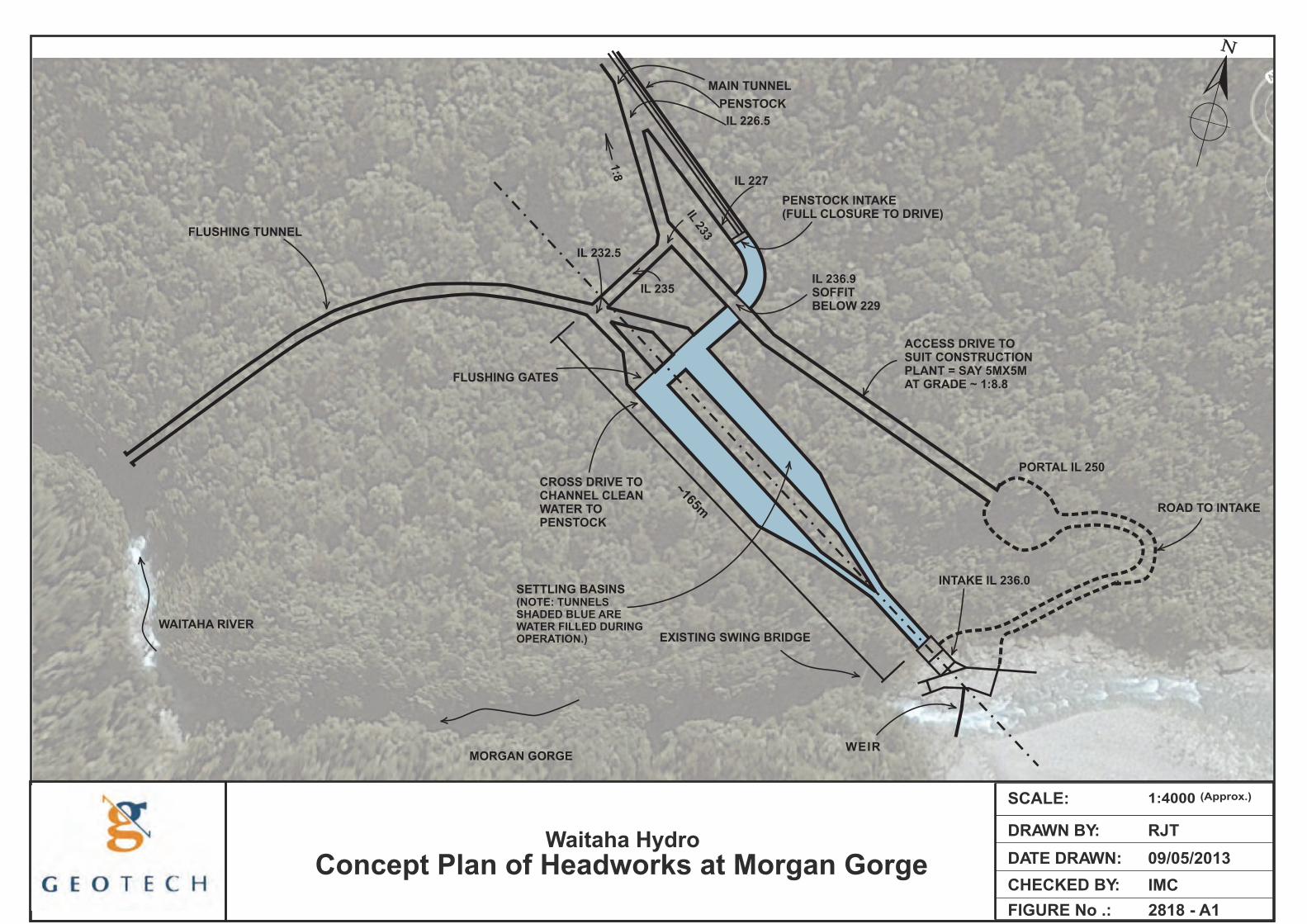
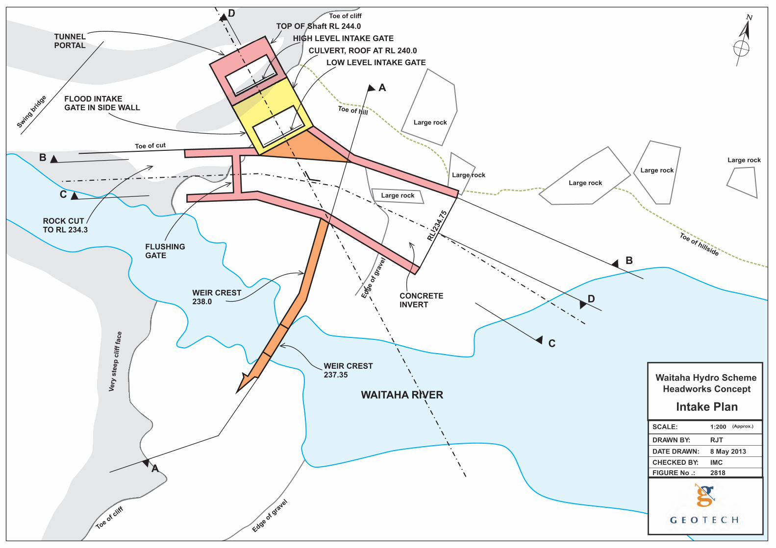
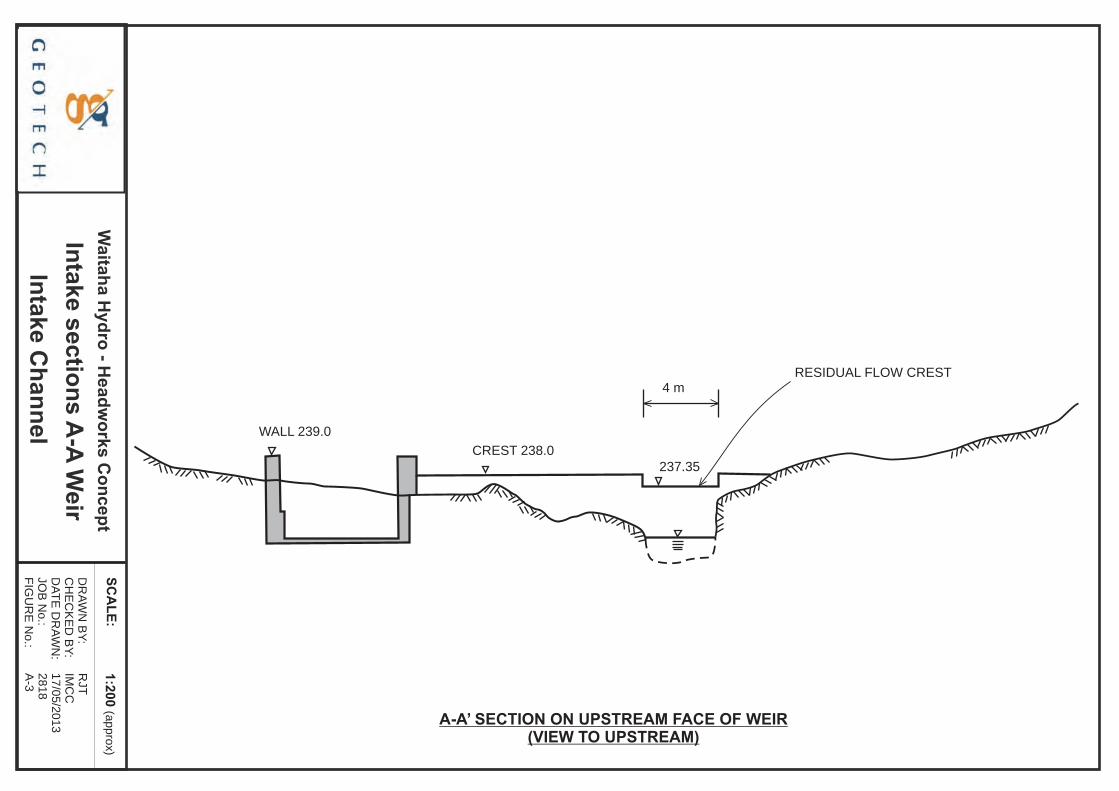
Any intake must allow for this substantial flood rise. Earlier work suggested that the backwater effect at the gorge entrance was the result of a partial constriction with a rock fall in the gorge, and that some work could be done to remove the constriction. Flow analysis of the narrow gorge section now indicates that the backwater is explained simply by the narrow width, and there is unlikely to be any way of reducing the flood depth. 3 Weir The weir is shown in plan on A-2 and in long section on A-3. It is a simple concrete wall with a crest level of RL238, which is generally 1 – 2m above the rock level on the right abutment (looking downstream). A reinforced concrete structure of about 1m width is envisaged, secured with rock anchors. The section across the river channel is likely to be 4 – 5m high, but at the chosen location, the channel is only about 4m wide, so that the structure will span horizontally as well as vertically. It is envisaged that this channel section will have a depressed crest at RL 237.35m. This will pass the residual flow, assumed to be 3.5 m3/s with the upstream water level at RL 238. This arrangement concentrates the residual flow into a chute and thus allows kayakers use of the river at all times. Other arrangements are also possible, including having one crest level throughout, or an irregular crest level or weir partially constructed from large boulders bolted and concreted into place to provide a more natural appearance. The section of weir across the channel can only be constructed with the river diverted. It is likely to be impractical to determine the depth of the channel or bed material until after dewatering, given the very turbulent flow at this location. Construction will require the diversion of the river through the completed intake channel to allow a coffer dam to be built across the river channel both upstream and downstream of the weir. This will be an unavoidably high risk part of the construction very exposed to flooding. It must be well planned and resourced to minimize the time in the river and exposure to flooding and damage. 4 Intake Channel This channel is designed to fulfill three functions
• Act as a diversion during construction of the weir across the river channel • Divert the river flow in an appropriate flow alignment to the scheme intake • Provide a sluicing channel in front of the intake to prevent most of the larger bedload
entering the intake. The rock platform on the right bank provides an excellent location for this channel. Blasting will be required to cut the channel into the rock by generally about 3m and the upstream corner of the gorge will have to be trimmed with a 6m high cut to provide a suitable alignment.
Waitaha Headworks Concept Page 4
Geotech Consulting Ltd 2818 – Issue 3 1 August 2013
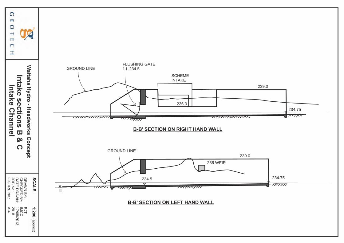
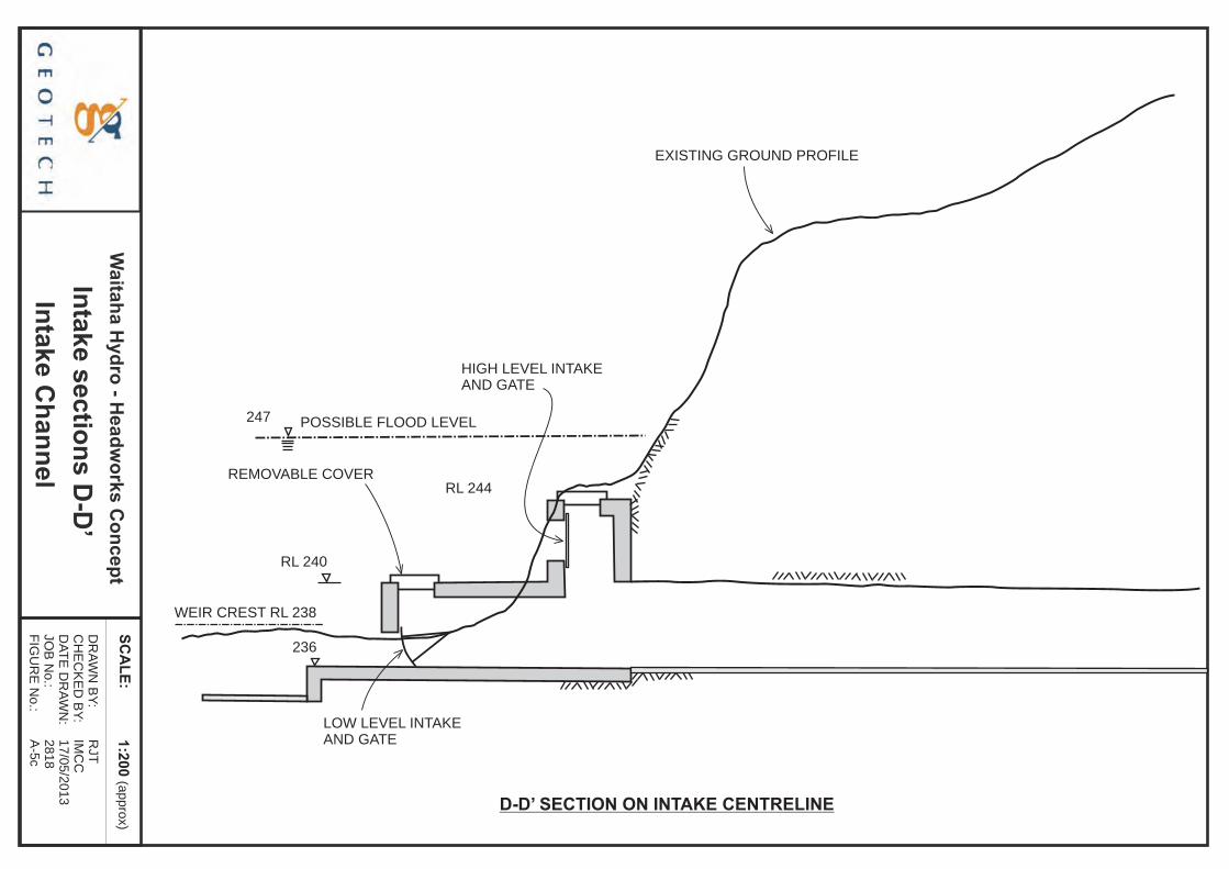
The floor will be concreted to provide better hydraulic conditions for sluicing sediment and the channel confined with side walls about 4.5m high. The alignment has been sketched to keep the channel sufficiently back from the river channel to allow the rock between to remain with low risk of being inadvertently damaged during excavation and thus allow the channel construction to continue with some security from flooding. A gravel bank is assumed to be built across the upstream end to keep small to moderate floods away from the site. The curved alignment assists in setting up a secondary flow which helps pull sediment away from the intake when the sluicing gate is operated. The channel is sized at 4m width at the gate to keep flow velocities high enough to entrain bed material and move it past the intake. The concept is for the intake channel to be completed prior to the weir construction. When the weir is to be built, the temporary stopbank would be removed and the river diverted into the channel. On completion of the weir, the gate can be shut and the intake becomes operable. 5 Intake The intake has been sized as a 5m wide passage out of the side of the intake channel. This opening will be controlled with a radial gate housed within the structure at the upstream end. The structure has been kept deliberately low and thus will be covered with a roof and removable hatch to allow infrequent maintenance access. The top of the structure will be subject to about 7m head of water during large floods and thus the structure will need to be substantial to withstand the imposed loading. A second auxiliary intake is to be located in a short shaft constructed within a slot cut into the rock face at the tunnel portal. This shaft will also be fitted with an access hatch at the top, and will house a second intake gate. The gate will normally be kept close, and will only open during periods of flood, when the sediment load likely at the lower intake level is likely to be too high to be handled effectively. Thus by shutting the lower gate and using the higher one, it should be possible to minimize bed load entrainment into the scheme. The intake structure is envisaged as integral with the tunnel portal. Because of the flood risk, the intake structure, higher level intake shaft and portal must be built before the tunnel is broken out. 6 Settling basin The water taken from the river will carry suspended sediment, and at times some bed load. To prevent undue wear on the turbine and penstock, as much of the coarser sediment as possible should be removed. The current concept is for a traditional settling basin designed to allow the flushing of sediment back to the river. This arrangement is proven but there are a number of other arrangements possible, with a potential for a reduction in amount of tunneling needed. From the portal the flow is taken by a 5m wide channel for about 25m into the hillside. At this point the tunnel and channel splits before widening and deepening to provide two ten metre wide settling basins. As the channels are 2.5m wide, and as the tunnel itself will need to be
Waitaha Headworks Concept Page 5
Geotech Consulting Ltd 2818 – Issue 3 1 August 2013
wider to provide access for tunneling plant during construction, the channels will need to be formed with side walls to about 1m height. The invert will also need to be concreted to provide the hydraulic smoothness required, unless a steeper gradient is adopted with an increase in head loss. The two basins are adopted as this allows flushing of one basin while still generating off the other, and reduces the width of the underground excavation. There is limited cover above the settling basin and two narrower tunnels are likely to encounter fewer problems with tunnel support than a single much wider cavern. The settling basin has been provisionally dimensioned at 60m long. No optimization has been carried out, and the length could change to be either shorter or longer (perhaps a range of +/- 20m). The floors will probably need to be concreted to provide the right hydraulic conditions for flushing, and the walls may need shotcreting to reduce water loss. At the downstream end there will be a weir to take the generation flow from the top of the basin into a cross channel which leads to the upper end of the main tunnel. The cross channel floor will be a concrete slab spanning over four channels, forming a continuation of the settling basin floor leading to four flushing gates. When open these discharge into the flushing tunnel to return sediment to the river (see 8, below). 7 Penstock intake The cross tunnel channel (refer A-1) takes the generation flow to the penstock intake. The channel will curve around to meet the top end of the main tunnel, where the penstock intake will be located. This is envisaged as a simple wall across the full section of the tunnel, fitted with a gate and penstock entry. This wall seals the settling basin from the main tunnel so that if the settling basin did become completely flooded, it would not spill to the main tunnel. The intake in the cross tunnel allows this feature, which also provides support to the wall on all sides and thus reduces the wall thickness requirements. The penstock will be located on the right hand side of the main tunnel to allow support directly to the tunnel wall at a bend likely to be needed towards the downstream end. The cross channel levels are determined by depth of flow and flushing channel height in the settling basin chambers, and the depth of submergence needed for the penstock intake. 8 Flushing tunnel The flushing gates will discharge into extensions of the main settling basin chambers and then into narrower adits which merge into one tunnel which curves to return to the river. The outlet to this tunnel is about half way down the gorge, downstream of one sharp bend at the downstream end of the very narrow gorge section, and on the outside a second bend, with the gorge becoming wider still downstream. The river bed has probably dropped about 15m from the top of the gorge to this point and this should mean the tunnel invert is about 10m above the river bed. The adit outlet should be above even extreme flood levels. Additional investigation, survey and modeling is needed before the location of the adit outlet can be confirmed.
Waitaha Headworks Concept Page 6
Geotech Consulting Ltd 2818 – Issue 3 1 August 2013
Flushing would normally be carried out during floods or on their recession when the river is already turbid and at relatively high levels. It is not envisaged that there will be any significant impact on river turbidity or that the discharged sediment will build any appreciable fan at the outlet. The flushing tunnel has been shown as 4m wide and a similar height, with a gradient of about 1 in 70. The actual dimensions will depend on what tunneling equipment is available; it may be more economical to create a larger cross section. A short drive is shown connecting the flushing tunnel and the main tunnel. This may be of use in allowing the flushing tunnel to be constructed independently of the settling basin area, but its primary role is to provide long term access for plant to the flushing tunnel and the settling basins for maintenance, repair, or clearing of blockages, should they occur. Small plant should be able to access the basins through the flushing gate openings. This short drive will need to be aligned vertically to prevent any water from the flushing tunnel flowing into the main tunnel, which will be at a lower level. 9 Access Tunnel Because of the need to construct the intake before breaking out the settling basin tunnel for both programming and risk reasons, a separate tunnel to a high level portal is needed. For a number of reasons, including the need for the penstock to be on the right hand side of the main tunnel and therefore access on the left, providing access to the flushing tunnel, clearance to the cross tunnel to the penstock intake, and maintaining a usable road gradient, the access tunnel will need to start about 60m downstream of the penstock intake and climb at about 1 in 8 gradient to pass over the cross tunnel. The alignment of this tunnel can be determined by the best location for the portal. It is assumed that a 5m by 5m cross section would be adequate; again the actual size may be determined by economics and available equipment. 10 Access Road. A short road is needed between the access tunnel portal and the intake structure for construction and maintenance. The alignment has been sketched as indicative only on Figure 1. It will necessitate some tree clearance, earthworks on a steep hillside, and river protection at the toe. 11 Construction sequence The following is a possible order of construction:
a) Form main tunnel to end of penstock b) Continue with access tunnel and high level portal. As well as providing access to the
intake, this also provides through tunnel ventilation and a second tunnel egress c) Excavate cross drive and access drive to flushing tunnel, construct access road to
intake d) Start intake structure and channel in the river bed e) Excavate settling basins, using the cross drive as access. The grade in the cross
drive is kept to an acceptable level to allow plant access.
Waitaha Headworks Concept Page 7
Geotech Consulting Ltd 2818 – Issue 3 1 August 2013
f) Concrete work to one settling basin g) Construct flushing tunnel h) Complete intake structure to safeguard portal from flooding i) Break out hydraulic tunnel to the portal and completed intake structure j) Complete concrete work in settling basins k) Construct penstock intake l) Complete intake works and weir m) Lay penstock
Note: it is assumed that all tunneling work involved with the excavation of the settling basins would involve mucking out to the downstream entrance. Two alternatives are possible: mucking out through the high level portal to a dump site in the bottom end of Kiwi Flat, or dumping out the flushing tunnel into the river. It is assumed that the latter is unacceptable. The former is possible but requires a longer road either through bush or up the river bed. 12 Operation The operation of the headworks may be quite complex. The following are some initial comments. To maintain the residual flow, the water level at the intake during low flow periods will need to be maintained at RL238. Therefore for river flows less than 25 m3/s, operation will need to be by means of the intake gate to control the inflow into the scheme and thus the water level at the weir and residual flow in the river. For flows above 25 m3/s, the water level could be controlled by the sluice gate, and for flows above 40 to 50 m3/s (this is indicative only and will depend on actual behavior of the river and intake) when bedload movement might be expected, the sluice gate should be opened to provide constant flushing past the intake. For flows higher than about 25 m3/s, the upstream water level is of little consequence and the intake gate operation would be better controlled by the water level in the settling basin. While excess flow through the basin would safely spill over the end weir and out the flushing channel, the higher than design flow would adversely impact on the settling basin performance – at a time when sediment is higher and the basin is really needed. Therefore it is desirable to keep the basin flow to the design level. As the river flow increases to above about RL243, the lower (main) intake gate might be best closed and the higher auxiliary gate opened, to reduce the entrainment of bed load into the intake, as discussed in section 4. The settling basins are set out so that they operate independently of each other. One can be flushed and the other operated. The generation flow is best controlled from the penstock intake. As drawn this channel has a water surface area of about 450m2. For an increase in generation flow of 1 m3/s, this gives little more than 20 seconds of storage to draw down 1m, if the inflow was constant. Additional volume may be needed to ease operational tolerances. If both settling basins could be incorporated into the buffer this would provide a total area of about 2000 m2. However, to do this would require the end weirs to be lowered with the effect that single basin operation would not be possible as water would flow out of the full basin and back into the drawn down basin. It may also be possible to move the penstock intake further down the main tunnel and increase the cross channel storage in this way.

DRAWN BY:
SCALE:
CHECKED BY:
DATE DRAWN:
FIGURE No .: 2818 - A1
RJT
1:4000 (Approx.)
09/05/2013Waitaha Hydro
Concept Plan of Headworks at Morgan GorgeIMC
ROAD TO INTAKE
CROSS DRIVE TO CHANNEL CLEAN WATER TO PENSTOCK
FLUSHING GATES
MORGAN GORGE
INTAKE IL 236.0
EXISTING SWING BRIDGE~165m
WAITAHA RIVER
FLUSHING TUNNEL
PORTAL IL 250
ACCESS DRIVE TO SUIT CONSTRUCTION PLANT = SAY 5MX5M AT GRADE ~ 1:8.8
IL 236.9 SOFFIT BELOW 229
PENSTOCK INTAKE(FULL CLOSURE TO DRIVE)
IL 227
IL 233
MAIN TUNNEL
PENSTOCK
IL 226.5
1:8
IL 232.5
IL 235
WEIR
SETTLING BASINS(NOTE: TUNNELS SHADED BLUE ARE WATER FILLED DURING OPERATION.)
Large rock
A
A
D
B
C
C
B
D
DRAWN BY:
SCALE:
CHECKED BY:
DATE DRAWN:
FIGURE No .: 2818
RJT
1:200 (Approx.)
8 May 2013
Waitaha Hydro SchemeHeadworks Concept
IMC
Intake Plan
CONCRETE INVERT
WAITAHA RIVER
FLUSHING GATE
ROCK CUT TO RL 234.3
FLOOD INTAKEGATE IN SIDE WALL
LOW LEVEL INTAKE GATE
Large rock
Large rock
Large rock
Large rock
Edge of g
rave
l
Toe of c
liff
Toe of cliff
Toe of hill
Toe of hillside
WEIR CREST237.35
WEIR CREST238.0
Edge
of gra
vel
Sw
ing
brid
ge
Toe of cut
Large rock
TUNNEL PORTAL
RL 2
34.7
5
Very
ste
ep
cliff
face
HIGH LEVEL INTAKE GATE
CULVERT, ROOF AT RL 240.0
TOP OF Shaft RL 244.0
Waita
ha H
yd
ro - H
ead
wo
rks C
on
cep
t
Inta
ke s
ectio
ns A
-A W
eir
Inta
ke C
han
nel
SC
AL
E:
DR
AW
N B
Y:
CH
EC
KE
D B
Y:
DA
TE
DR
AW
N:
JOB
No.:
FIG
UR
E N
o.:
1:2
00 (a
ppro
x)
RJT
IMC
C17/0
5/2
01
328
18
A-3
A-A’ SECTION ON UPSTREAM FACE OF WEIR(VIEW TO UPSTREAM)
WALL 239.0
RESIDUAL FLOW CREST
237.35CREST 238.0
4 m
Waita
ha H
yd
ro - H
ead
wo
rks C
on
cep
t
Inta
ke s
ectio
ns B
& C
Inta
ke C
han
nel
SC
AL
E:
DR
AW
N B
Y:
CH
EC
KE
D B
Y:
DA
TE
DR
AW
N:
JOB
No.:
FIG
UR
E N
o.:
1:2
00 (a
ppro
x)
RJT
IMC
C17/0
5/2
01
328
18
A-4
FLUSHING GATE1.L 234.5GROUND LINE
239.0
234.75
236.0
SCHEMEINTAKE
B-B’ SECTION ON RIGHT HAND WALL
B-B’ SECTION ON LEFT HAND WALL
234.5
GROUND LINE
238 WEIR
239.0
234.75
Waita
ha H
yd
ro - H
ead
wo
rks C
on
cep
t
Inta
ke s
ectio
ns D
-D’
Inta
ke C
han
nel
SC
AL
E:
DR
AW
N B
Y:
CH
EC
KE
D B
Y:
DA
TE
DR
AW
N:
JOB
No.:
FIG
UR
E N
o.:
1:2
00 (a
pp
rox)
RJT
IMC
C17/0
5/2
013
28
18
A-5
c
D-D’ SECTION ON INTAKE CENTRELINE
LOW LEVEL INTAKEAND GATE
HIGH LEVEL INTAKEAND GATE
EXISTING GROUND PROFILE
RL 244
POSSIBLE FLOOD LEVEL
REMOVABLE COVER
RL 240
WEIR CREST RL 238
247
236