Embed Size (px)
Citation preview
DOWNLOAD this issue ofCompositesWorld
in a low-res PDF format— CLICK HERE —
JANUARY 2017
VOL 3 No- 1 A property of Gardner Business Media
Carbon Fiber 2016 conference yields plentiful supply/demand data / 24
CW Plant Tour: Tri-Mack Plastics Mfg., Bristol, RI, US / 26
Multi-material vehicle: CFRP overmolded steel differential housing / 44
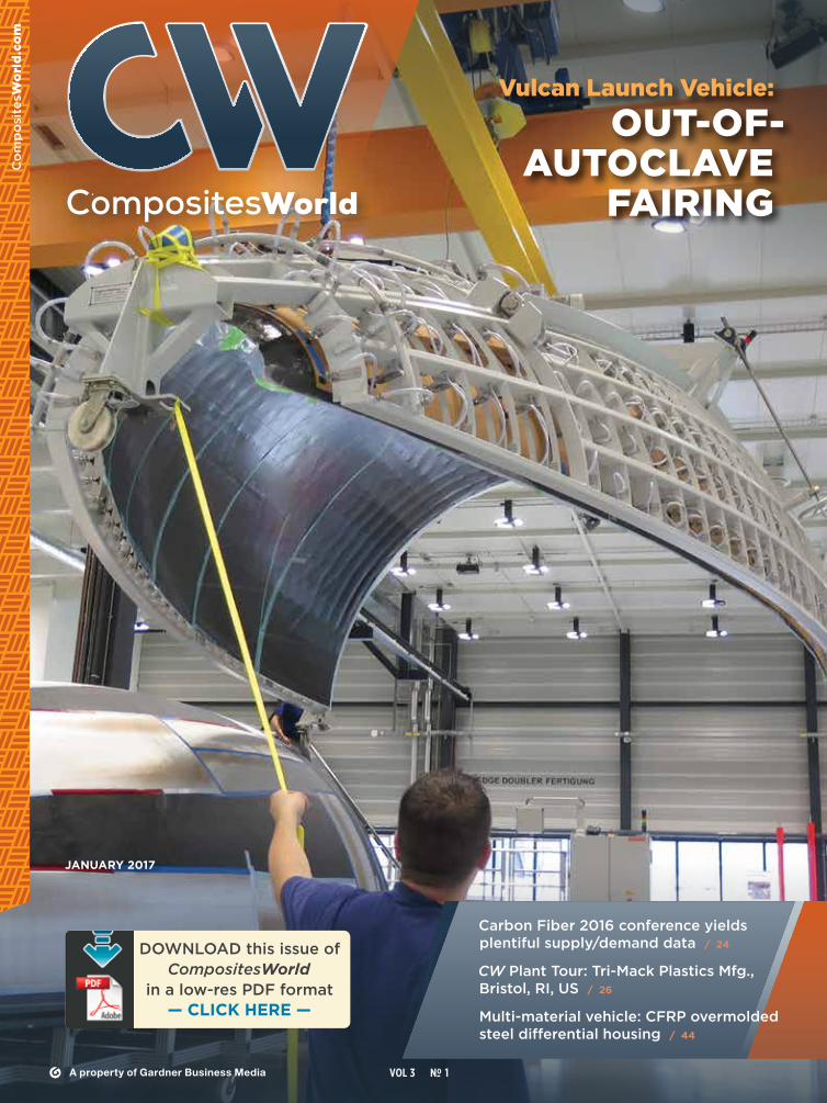
Vulcan Launch Vehicle: OUT-OF-
AUTOCLAVE FAIRING

Visit compositesone.com
Working with Composites One is a unique partnership with our PEOPLE. From regional customer service reps and technical sales teams,
to local support teams at over 35 distribution centers in the U.S. and throughout Canada, we’ll make sure you find what you need, and receive it when you need it.
As your partner, we’ll give you access to emerging market expertise and process application know-how, and do what it takes to help grow your business. We’ll also
provide you with the unmatched service and support you should expect from North America’s leading composites distributor.
That’s the power of Partnership. The Power of One – Composites One.
800.621.8003 | www.compositesone.com | www.b2bcomposites.com
People | Product | Process | Performance
“At Composites One, we make it our business to know your business.”Gary Yoder, Driver, Goshen, IN
CMP-434 CW FULL Pg PEOPLE ad Jan 2017 FINAL.indd 1 12/8/16 10:27 AM
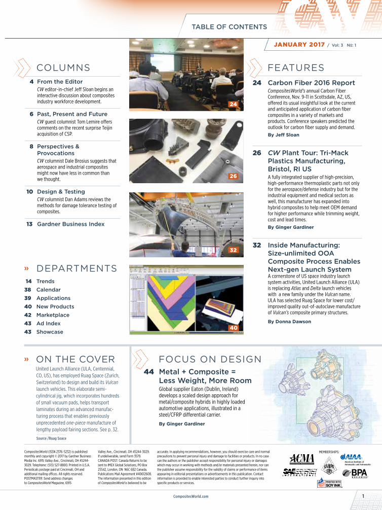
COLUMNS 4 From the Editor
CW editor-in-chief Jeff Sloan begins an interactive discussion about composites industry workforce development.
6 Past, Present and FutureCW guest columnist Tom Lemire offers comments on the recent surprise Teijin acquisition of CSP.
8 Perspectives & ProvocationsCW columnist Dale Brosius suggests that aerospace and industrial composites might now have less in common than we thought.
10 Design & TestingCW columnist Dan Adams reviews the methods for damage tolerance testing of composites.
13 Gardner Business Index
» DEPARTMENTS 14 Trends38 Calendar39 Applications40 New Products42 Marketplace 43 Ad Index 43 Showcase
» ON THE COVER United Launch Alliance (ULA, Centennial,
CO, US), has employed Ruag Space (Zurich, Switzerland) to design and build its Vulcan launch vehicles. This elaborate semi-cylindrical jig, which incorporates hundreds of small vacuum pads, helps transport laminates during an advanced manufac-turing process that enables previously unprecedented one-piece manufacture of lengthy payload fairing sections. See p. 32.
Source /Ruag Soace
FOCUS ON DESIGN44 Metal + Composite =
Less Weight, More Room Global supplier Eaton (Dublin, Ireland)develops a scaled design approach for metal/composite hybrids in highly loaded automotive applications, illustrated in a steel/CFRP differential carrier.
By Ginger Gardiner
CompositesWorld (ISSN 2376-5232) is published monthly and copyright © 2017 by Gardner Business Media Inc. 6915 Valley Ave., Cincinnati, OH 45244-3029. Telephone: (513) 527-8800. Printed in U.S.A. Periodicals postage paid at Cincinnati, OH and additional mailing offices. All rights reserved. POSTMASTER: Send address changes to CompositesWorld Magazine, 6915
MEMBERSHIPS:Valley Ave., Cincinnati, OH 45244-3029. If undeliverable, send Form 3579.CANADA POST: Canada Returns to be sent to IMEX Global Solutions, PO Box 25542, London, ON N6C 6B2 Canada. Publications Mail Agreement #40612608. The information presented in this edition of CompositesWorld is believed to be
accurate. In applying recommendations, however, you should exercise care and normal precautions to prevent personal injury and damage to facilities or products. In no case can the authors or the publisher accept responsibility for personal injury or damages which may occur in working with methods and/or materials presented herein, nor can the publisher assume responsibility for the validity of claims or performance of items appearing in editorial presentations or advertisements in this publication. Contact information is provided to enable interested parties to conduct further inquiry into specific products or services.
FEATURES24 Carbon Fiber 2016 Report
CompositesWorld’s annual Carbon Fiber Conference, Nov. 9-11 in Scottsdale, AZ, US, offered its usual insightful look at the current and anticipated application of carbon fiber composites in a variety of markets and products. Conference speakers predicted the outlook for carbon fiber supply and demand.By Jeff Sloan
26 CW Plant Tour: Tri-Mack Plastics Manufacturing, Bristol, RI USA fully integrated supplier of high-precision, high-performance thermoplastic parts not only for the aerospace/defense industry but for the industrial equipment and medical sectors as well, this manufacturer has expanded into hybrid composites to help meet OEM demand for higher performance while trimming weight, cost and lead times.By Ginger Gardiner
32 Inside Manufacturing: Size-unlimited OOA Composite Process Enables Next-gen Launch SystemA cornerstone of US space industry launch system activities, United Launch Alliance (ULA) is replacing Atlas and Delta launch vehicles with a new family under the Vulcan name. ULA has selected Ruag Space for lower cost/improved quality out-of-autoclave manufacture of Vulcan’s composite primary structures.
By Donna Dawson
32
26
24
40
CompositesWorld.com 1
TABLE OF CONTENTS
JANUARY 2017 / Vol: 3 No–: 1
PUBLISHER Ryan Delahanty [email protected]
EDITOR-IN-CHIEF Jeff Sloan [email protected]
MANAGING EDITOR Mike Musselman [email protected]
SENIOR EDITOR Sara Black [email protected]
SENIOR EDITOR Ginger Gardiner [email protected]
MANAGING EDITOR – Heather Caliendo ELECTRONIC PRODUCTS [email protected]
GRAPHIC DESIGNER Susan Kraus [email protected]
MARKETING MANAGER Kimberly A. Hoodin [email protected]
CW SALES GROUP
MIDWESTERN US & INTERNATIONAL Ryan Mahoney / district manager [email protected]
EASTERN US SALES OFFICE Barbara Businger / district manager [email protected]
MOUNTAIN, SOUTHWEST & Rick Brandt / district manager WESTERN US SALES OFFICE [email protected]
EUROPEAN SALES OFFICE Eddie Kania / european sales mgr. [email protected]
HEADQUARTERS
6915 Valley Ave., Cincinnati, OH 45244-3029Phone 513-527-8800 Fax 513-527-8801
COMPOSITESWORLD IS A PROPERTY OF
chairman & ceo Rick Kline, CBC coo Melissa Kline Skavlem president Rick Kline, Jr. senior vp, content Tom Beard director of market intelligence Steve Kline, Jr. treasurer Ernie Brubaker advertising manager Bill Caldwell director of editorial operations Kate Hand director of marketing and events Dave Necessary creative department manager Rhonda Weaver creative director Jeff Norgord advertising production manager Becky Helton
Modern Machine Shop Moldmaking Technology Plastics Technology Automotive Design & Production Production Machining Products Finishing
GARDNER BUSINESS MEDIA ALSO PUBLISHES
@CompositesWrld
CW CONTRIBUTING WRITERS
Dale Brosius [email protected] Donna Dawson [email protected] Michael LeGault [email protected] Peggy Malnati [email protected] Karen Wood [email protected]
CompositesWorld.com
ANNIVERSARY
02HPC
CharterAdvertiser
+1 (775) 827-6568 • www.abaris.com
ACTIVE TRAINING IN: • ENGINEERING • MANUFACTURING • REPAIR
DIRECT SERVICES:• ENGINEERING • ONSITE TRAINING • CONSULTATION
ACTIVE TRAINING IN:• ENGINEERING • MANUFACTURING • REPAIR
The Abaris Advantage Will Keep Your Advanced
Composite Program Soaring
2 JANUARY 2017 CompositesWorld

It’s free. It’s remote. It’s informative. It’s convenient.
SIGN UP TODAY!
Braided Fabrics Offer Significant Cost Savings Through Simple Processing, Reduction In Waste, & Superior Performance
DATE AND TIME:Jan. 26, 20172:00 PM EST
BILLY WOODProgram Manager -
Braided Fabrics A&P TECHNOLOGY
braider.com
PRESENTED BY:
Reg Link: http://short.compositesworld.com/AP126REGISTER TODAY FOR WEBINAR AT:
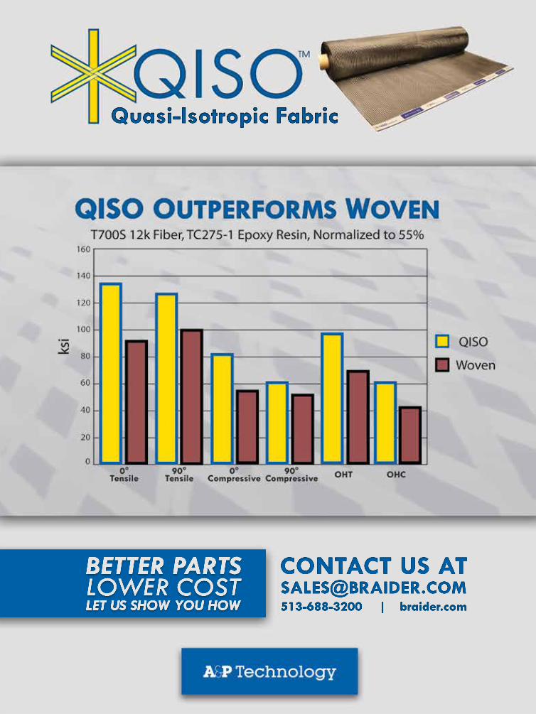
EVENT DESCRIPTION: A&P Technology’s braided fabrics are replacing woven fabrics in applications driven by light-weighting and cost-efficiency. QISO®, a quasi-isotropic fabric in a single layer, enables re-duced lay-up time, less waste and superior impact resistance. Bimax®, a ±45° fabric stabilized with hot melt axials, provides easy lay-up without concern over misorientation, and TX-45™, a true ±45° is much lower cost than the incumbent spirally slit woven material, and more cost-efficient than ±45 materials produced by cutting diagonally 0/90 woven fabrics.
PARTICIPANTS WILL LEARN: • QISO, a single-layer, quasi-isotropic fabric, offers cost and process savings, high strength, damage tolerance, impact resistance, dimensional stability, low CTE and simplifies the build of complex curvatures.• Testing comparing QISO and plain weave quasi-isotropic laminates of the same thickness. • Hybrid triaxial fabrics that can be created in a single layer.• Braided ±45° braided fabrics that can be produced in a variety of widths and areal weights.
EVENT DESCRIPTION: The drive to boost aircraft operating efficiency continues to fuel the adoption of composites in aeroengines. This market demand, combined with recent and continuing advances in composite material technologies, is shifting the competitive landscape for aeroengine OEMs and their supply chains. In this webinar, John O’Connor will discuss best practices for composite development in the aeroengine industry and provide an overview of technology that is making it faster to develop composite definitions that support a full digital thread across the entire development process.
Join us as we discuss the use of Fibersim software to support analysis, design, and manufacturing of composite aeroengine components.
TOPICS TO BE DISCUSSED:• Understanding best practices of composite design and engineering in the aeroengine industry• Industry trends related to engineering and design of composites for aeroengines• How technology can support a digital thread for composites aeroengine components• Introduction to Siemens PLM Software’s composite development solutions for analysis, design, and manufacturing
Digitalization of Composite Aeroengine Development
DATE AND TIME:Jan. 25, 20172:00 PM EST
JOHN O’CONNORDirector of Product and Market Strategy
SIEMENS PLM SOFTWARE
siemens.com
PRESENTED BY:
Reg Link: http://short.compositesworld.com/Siemens125REGISTER TODAY FOR WEBINAR AT:
0117_CW_Webinar ad.indd 1 12/20/2016 12:38:04 PM
JANUARY 20174 CompositesWorld
FROM THE EDITOR
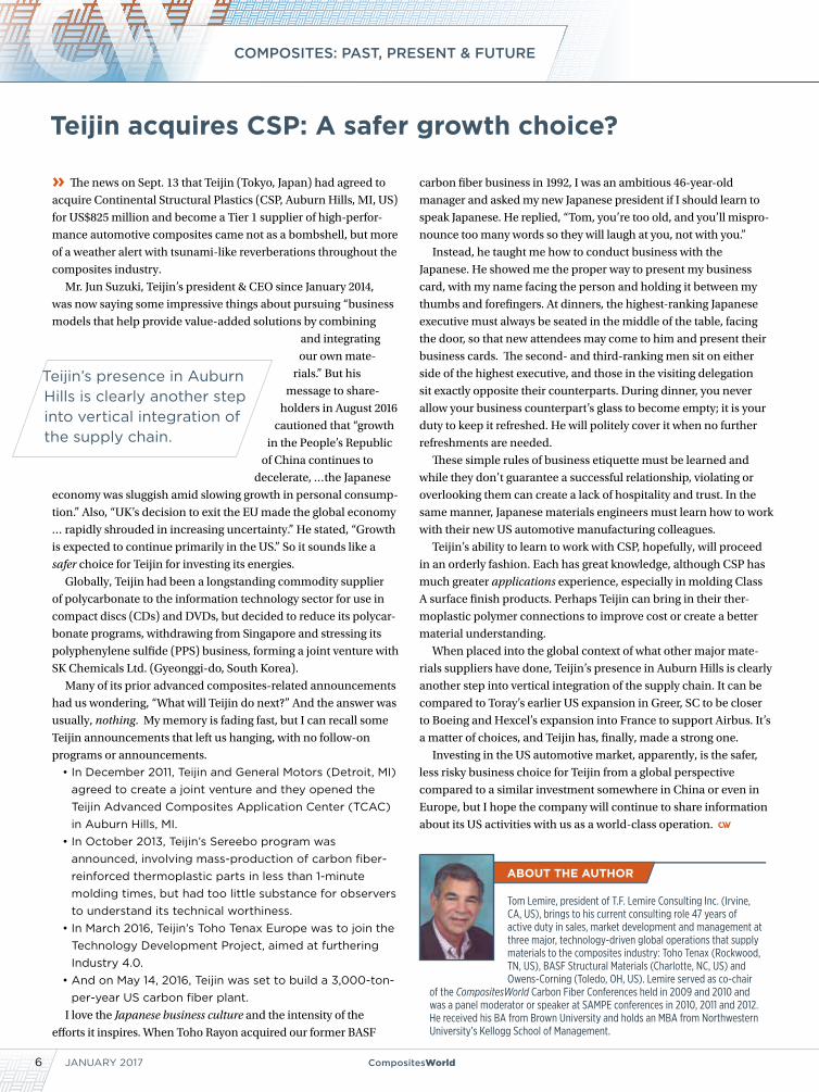
» My wife and I have three boys. The youngest is 17, a junior in
high school and starting to think more seriously about his life after
high school. Like a lot of kids his age, he has a variety of interests
and skills, but no clear sense yet of how he might apply these in
college or career. And,
like a lot of kids his age,
he doesn’t know what he
doesn’t know about what it
means to be an engineer, sales
person, sous chef, welder, elec-
trician, attorney — or any other
job. Further, the odds are pretty good that the job does not yet exist
that my youngest son is likely to turn into a career.
So, how do my wife and I help guide him as he begins to assess
his post-high school options? Like a lot of parents, we want our
kids to find meaningful work in which they can apply their skills
and interests and feel a sustainable sense of satisfaction. We want
them to have the intellectual and emotional tools necessary to
adapt to a fast-changing work world. We want to empower them
with the desire and energy to pursue professional opportunities as
they present themselves. We want them to earn a living wage.
Because he’s my son, and because — like a lot of you — my
work spills over into my family life, my youngest is keenly aware
of composite materials and the composites industry. He knows
how composites are being applied in aerospace, automotive,
wind energy and many other end-markets. He understands that
there is tension between legacy materials and composites as the
latter displaces the former. He knows that as a relatively small but
expanding manufacturing community, the world of composites
fabrication is feeling some of the growing pains that come with the
application of advanced materials.
My advice, which my son at least seems to be listening to: Pursue
a degree in business, but sprinkle in coursework on supply-chain
management, manufacturing management and technical mate-
rials. Then, pursue work on the business-development side of
the composites industry, helping customers understand what
composites are and how they can be applied. There is, I argue,
great need for such skills — among many — in this industry.
We’ll see, over the next few years, just what path my son
chooses. But regardless of his choices, the truth remains that
many of us are closely aligned with two populations that could be
of great help to each other: Young people in need of career options
and guidance, and a composites industry in need of new talent.
Connecting the two will be of paramount importance to the future of
composites and to the future for many of our kids.
This, of course, is not new news. Baby Boomers are in the midst
of a well-publicized and very long retirement process, taking with
them decades of knowledge and experience that will be difficult to
replace. Many of you likely are seeing this happen in your own work-
place, or see it coming. The question is, how do we respond?
The short answer is that the response is already underway. From
Seattle to Salt Lake City to Toulouse, teachers, professors, commu-
nity colleges and manufacturers are working very hard — often
together — to help train students, like my son, for work in the
composites world. They’re reaching out to college-age kids, high
school-age kids and adults, helping them understand what the
opportunities are, and then helping them prepare to take advantage
of those opportunities.
CW will, in 2017, take a closer look at how the composites
industry is tackling workforce development, and we will help you
understand how these efforts can help you and your business put
new talent into your facility. And, perhaps most importantly, we
hope to stimulate thought and discussion about what each of us can
do to help guide and mentor the students around us, to help them
see, appreciate and pursue the opportunities composites offer.
As we work on this story, I encourage you to contact me directly if
you or your company is involved in workforce development. What is
your goal? What is your strategy? How have you deployed resources?
Who are you working with? How successful have you been? What
lessons have you learned?
You can reach me at [email protected]. I hope to hear
from you.
How to develop the next-generation
workforce?
JEFF SLOAN — Editor-In-Chief
BETTER PARTSLOWER COSTLET US SHOW YOU HOW
CONTACT US AT [email protected]
Quasi-Isotropic Fabric
513-688-3200 | braider.com
07106 AP Technologies.indd 1 6/8/16 11:11 AM
JANUARY 20176 CompositesWorld
COMPOSITES: PAST, PRESENT & FUTURE
» The news on Sept. 13 that Teijin (Tokyo, Japan) had agreed to
acquire Continental Structural Plastics (CSP, Auburn Hills, MI, US)
for US$825 million and become a Tier 1 supplier of high-perfor-
mance automotive composites came not as a bombshell, but more
of a weather alert with tsunami-like reverberations throughout the
composites industry.
Mr. Jun Suzuki, Teijin’s president & CEO since January 2014,
was now saying some impressive things about pursuing “business
models that help provide value-added solutions by combining
and integrating
our own mate-
rials.” But his
message to share-
holders in August 2016
cautioned that “growth
in the People’s Republic
of China continues to
decelerate, …the Japanese
economy was sluggish amid slowing growth in personal consump-
tion.” Also, “UK’s decision to exit the EU made the global economy
… rapidly shrouded in increasing uncertainty.” He stated, “Growth
is expected to continue primarily in the US.” So it sounds like a
safer choice for Teijin for investing its energies.
Globally, Teijin had been a longstanding commodity supplier
of polycarbonate to the information technology sector for use in
compact discs (CDs) and DVDs, but decided to reduce its polycar-
bonate programs, withdrawing from Singapore and stressing its
polyphenylene sulfide (PPS) business, forming a joint venture with
SK Chemicals Ltd. (Gyeonggi-do, South Korea).
Many of its prior advanced composites-related announcements
had us wondering, “What will Teijin do next?” And the answer was
usually, nothing. My memory is fading fast, but I can recall some
Teijin announcements that left us hanging, with no follow-on
programs or announcements.
• In December 2011, Teijin and General Motors (Detroit, MI) agreed to create a joint venture and they opened the Teijin Advanced Composites Application Center (TCAC) in Auburn Hills, MI.
• In October 2013, Teijin’s Sereebo program was announced, involving mass-production of carbon fiber-reinforced thermoplastic parts in less than 1-minute molding times, but had too little substance for observers to understand its technical worthiness.
• In March 2016, Teijin’s Toho Tenax Europe was to join the Technology Development Project, aimed at furthering Industry 4.0.
• And on May 14, 2016, Teijin was set to build a 3,000-ton-per-year US carbon fiber plant.
I love the Japanese business culture and the intensity of the
efforts it inspires. When Toho Rayon acquired our former BASF
carbon fiber business in 1992, I was an ambitious 46-year-old
manager and asked my new Japanese president if I should learn to
speak Japanese. He replied, “Tom, you’re too old, and you’ll mispro-
nounce too many words so they will laugh at you, not with you.”
Instead, he taught me how to conduct business with the
Japanese. He showed me the proper way to present my business
card, with my name facing the person and holding it between my
thumbs and forefingers. At dinners, the highest-ranking Japanese
executive must always be seated in the middle of the table, facing
the door, so that new attendees may come to him and present their
business cards. The second- and third-ranking men sit on either
side of the highest executive, and those in the visiting delegation
sit exactly opposite their counterparts. During dinner, you never
allow your business counterpart’s glass to become empty; it is your
duty to keep it refreshed. He will politely cover it when no further
refreshments are needed.
These simple rules of business etiquette must be learned and
while they don’t guarantee a successful relationship, violating or
overlooking them can create a lack of hospitality and trust. In the
same manner, Japanese materials engineers must learn how to work
with their new US automotive manufacturing colleagues.
Teijin’s ability to learn to work with CSP, hopefully, will proceed
in an orderly fashion. Each has great knowledge, although CSP has
much greater applications experience, especially in molding Class
A surface finish products. Perhaps Teijin can bring in their ther-
moplastic polymer connections to improve cost or create a better
material understanding.
When placed into the global context of what other major mate-
rials suppliers have done, Teijin’s presence in Auburn Hills is clearly
another step into vertical integration of the supply chain. It can be
compared to Toray’s earlier US expansion in Greer, SC to be closer
to Boeing and Hexcel’s expansion into France to support Airbus. It’s
a matter of choices, and Teijin has, finally, made a strong one.
Investing in the US automotive market, apparently, is the safer,
less risky business choice for Teijin from a global perspective
compared to a similar investment somewhere in China or even in
Europe, but I hope the company will continue to share information
about its US activities with us as a world-class operation.
Teijin’s presence in Auburn Hills is clearly another step into vertical integration of the supply chain.
Teijin acquires CSP: A safer growth choice?
Tom Lemire, president of T.F. Lemire Consulting Inc. (Irvine, CA, US), brings to his current consulting role 47 years of active duty in sales, market development and management at three major, technology-driven global operations that supply materials to the composites industry: Toho Tenax (Rockwood, TN, US), BASF Structural Materials (Charlotte, NC, US) and Owens-Corning (Toledo, OH, US). Lemire served as co-chair
of the CompositesWorld Carbon Fiber Conferences held in 2009 and 2010 and was a panel moderator or speaker at SAMPE conferences in 2010, 2011 and 2012. He received his BA from Brown University and holds an MBA from Northwestern University’s Kellogg School of Management.
0117 IACMI.indd 1 12/13/16 1:37 PM
JANUARY 20178 CompositesWorld
PERSPECTIVES & PROVOCATIONS
» Late in 2014, I wrote several columns that pointed to a conver-
gence between the aerospace and industrial markets for advanced
composites. Several signs pointed to this. SAMPE and ACMA
came together that October to form a single CAMX trade show
and conference, covering all composites applications. Composites
Technology and High-Performance Composites became this single
magazine, called CompositesWorld. In the final issue of Compos-
ites Technology (December 2014), I opined, “We’re moving toward
a time when aerospace and automotive technical advances will be
interchange-
able and extend
well beyond the
use of carbon
fiber.” Additional
columns in the
months following
built on this theory
of convergence, noting
the contributions of aerospace, like software tools for composites
and nondestructive evaluation to the advances of composites in
industrial applications, and the efforts in high-speed fabrication in
automotive finding eventual use in aerospace.
The convergence model can be illustrated by two highways
coming together to form a super-highway to a common desti-
nation. After decades of crossing widely disparate materials,
processes and designs — both markets now chase similar objec-
tives for multi-material solutions, lower costs and higher volumes.
But what if this isn’t a merging of traffic, but merely an inter-
section? Or, to continue the highway metaphor, a “roundabout,”
where two streams of traffic enter, but the majority continues out
via separate roads to different destinations? What if the past two
years have simply been a transient moment in time and tech-
nology where there was a lot of common territory?
The event that triggered these thoughts was the Composites-
World Carbon Fiber conference in November. The first day was
very aerospace-focused. Day two focused on automotive and
low-cost, alternative precursors for carbon fiber. As I listened to
presentations, it struck me that each market faces very different
challenges. And that solutions will differ widely as well.
Start with carbon fiber. The major suppliers of aerospace-qual-
ified carbon fiber could cut the price in half, and it would have a
negligible effect on the size of the aerospace carbon fiber market.
It is just not that sensitive to material pricing, which represents
less than 20% of part costs. On the other hand, if the price of indus-
trial-grade carbon fiber were suddenly reduced by 50%, it would
open big opportunities in automotive and wind energy markets.
One could argue that this is a prerequisite to achieve significant
penetration and helps explain the strong interest in alternative
precursors such as textile PAN, bio-based PAN and pitch.
Significant levels of automation are being developed for both
aerospace and automotive. A lot of effort is going into machines to
make simple, repetitive carbon fiber elements for aircraft — beams,
stringers and frames, for example. This is in addition to multi-
million-dollar fiber placement machines already prevalent in wing
and fuselage layup, where the molds remain stationary and only
the gantry and heads move. The layup machines under develop-
ment for automotive are focused on small- to medium-sized parts,
principally laying up 2D patterns, using wider tapes, with shaping
happening during the molding process. These machines have rela-
tively small footprints, move the table as much as the head, and are
a fraction of the cost of the aerospace machinery.
Finally, the markets’ volume levers are distinctly divergent.
Chris Red of Composites Forecasts and Consulting (Mesa, AZ, US)
estimates that commercial aircraft structures consumed 7,500 MT
of carbon fiber in 2016, and this will grow to slightly more than
10,100 MT in 2025, an increase of about 35%. This represents matu-
ration of widebody aircraft programs and organic market growth.
Should Boeing and Airbus elect to put carbon fiber wings on every
narrowbody aircraft built (admittedly, a very optimistic scenario)
this would add 7,000 MT to this forecast, at 5 MT per aircraft,
assuming growth to 1,400 aircraft per year. For OEM automotive,
Red’s numbers go from just under 12,000 MT to almost 33,000 MT
in the same period, nearly tripling the market. And his numbers
might be low. Andreas Wuellner of SGL Carbon Fibers (Wies-
baden, Germany) envisions 20% of the world’s 100 million vehicles
built in 2025 using 2 kg each — an annual market of 40,000 MT.
This isn’t exactly a stretch, either. It could easily be double or even
quadruple this figure with just a few technology breakthroughs.
As both markets drive through the roundabout into the future,
we could be looking at very distinct industries, with different casts
of suppliers, manufacturers and technologies. And surprisingly
little crossover.
Aerospace and industrial composites: Now on divergent paths?
The aerospace and industrial markets’ advanced compo- sites challenges and their solutions will differ widely.
Dale Brosius is the chief commercialization officer for the Institute for Advanced Composites Manufacturing Innovation (IACMI, Knoxville, TN, US), a US Department of Energy (DoE)-sponsored public/private partnership targeting high-volume applications of composites in energy-related industries. He is
also head of his own consulting company and his career has included positions at US-based firms Dow Chemical Co. (Midland, MI), Fiberite (Tempe, AZ) and successor Cytec Industries Inc. (Woodland Park, NJ), and Bankstown Airport, NSW, Australia-based Quickstep Holdings. He also served as chair of the Society of Plastics Engineers Composites and Thermoset Divisions. Brosius has a BS in chemical engineering from Texas A&M University and an MBA.

MARCH 6–9, 2017 | EXHIBITS: MARCH 7–8FORT WORTH (TX) CONVENTION CENTERAERODEFEVENT.COM
COLLABORATION FOR THE FUTURE OF AEROSPACE.AeroDef Manufacturing 2017 is the launch pad for mission-critical technologies, strategies and industry connections.
Attend. Exhibit. Sponsor.
Join top-level aerospace and defense managers, executives and business owners who will gather at AeroDef to find solutions for accelerating delivery, increasing affordability and driving innovations throughout the manufacturing supply chain.
The connections you form here could help your business take off in ways you never imagined.
0117 SME.indd 1 12/13/16 12:59 PM
JANUARY 201710 CompositesWorld
DESIGN & TESTING
» Damage tolerance refers to the capability of a damaged
composite laminate or structure to maintain its original
strength and stiffness. Typically, the damage is produced by
drop-weight impacting, which can cause extensive internal
damage that is difficult to detect by visual inspection. Damage
tolerance testing of composites most often is performed under
compression loading because compression strengths are lower
than tension strengths and, therefore, more critical in many
designs. Additionally, impact damage typically has a greater
effect on the compression strength. Compression-after-impact
(CAI) tests thus are widely used for assessing composite
damage tolerance. For applications in which other loadings are
critical, however, other types of tests may be used. For example,
damage tolerance of composite pressure vessels is better
assessed using tension-loaded specimens following impact.
As discussed in my October 2016 column, damage tolerance
testing follows the assessment of damage resistance, which
focuses on the ability of a composite material or structure to
resist the formation of damage.
Currently the most widely used standard test method for
damage tolerance of composites is ASTM D 71371. Not stan-
dardized by ASTM until 2005, it originated as a Boeing standard
(BSS-72602) in 1982, and is still commonly referred to as the
Boeing CAI test. In this test, a 100-mm wide by 150-mm long flat
composite specimen is used, with a suggested thickness range
of 4-6 mm. Although any balanced and symmetric laminate is
acceptable, the use of [45°/90°/-45°/0°]ns quasi-isotropic lami-
nates is suggested for use in material comparisons. The test
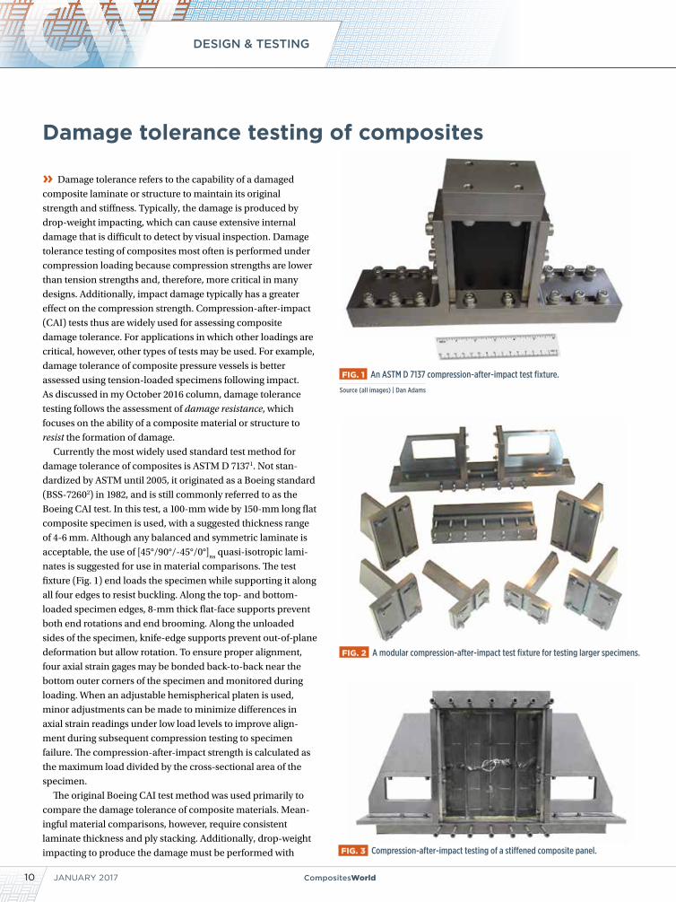
fixture (Fig. 1) end loads the specimen while supporting it along
all four edges to resist buckling. Along the top- and bottom-
loaded specimen edges, 8-mm thick flat-face supports prevent
both end rotations and end brooming. Along the unloaded
sides of the specimen, knife-edge supports prevent out-of-plane
deformation but allow rotation. To ensure proper alignment,
four axial strain gages may be bonded back-to-back near the
bottom outer corners of the specimen and monitored during
loading. When an adjustable hemispherical platen is used,
minor adjustments can be made to minimize differences in
axial strain readings under low load levels to improve align-
ment during subsequent compression testing to specimen
failure. The compression-after-impact strength is calculated as
the maximum load divided by the cross-sectional area of the
specimen.
The original Boeing CAI test method was used primarily to
compare the damage tolerance of composite materials. Mean-
ingful material comparisons, however, require consistent
laminate thickness and ply stacking. Additionally, drop-weight
impacting to produce the damage must be performed with
Damage tolerance testing of composites
FIG. 1 An ASTM D 7137 compression-after-impact test fixture.
Source (all images) | Dan Adams
FIG. 2 A modular compression-after-impact test fixture for testing larger specimens.
FIG. 3 Compression-after-impact testing of a stiffened composite panel.
CompositesWorld.com 11
consistent impactor shape, impact energy and specimen support
conditions, because these considerations affect the damage state
produced. Since the CAI strength is highly dependent on all of
these variables, it is considered a structural rather than a material
property.
Although ASTM D 7137 cautions against the use of test results
in establishing design allowables, the
CAI strengths obtained are often used to
determine the reductions in maximum
compression stress or strain due to impact
damage in actual composite structures.
When that is the case, the composite
laminate used in the test specimen is
selected to represent the laminate to be
used in the finished part. Similarly, the
impactor shape, impact energy and support conditions used when
impacting the specimen may be selected to represent impact
threats that the finished part will face in service.
Another common practice is to use impact energy levels that
produce barely visible impact damage (BVID) that’s difficult to
detect during a visual inspection of the composite structure. In
contrast, test specimen size has often remained at the original
100- by 150-mm dimensions regardless of the intended applica-
tion. For that reason, questions persist about whether or not CAI
strengths obtained using this relatively small specimen can be
applied to larger parts or more complex geometries. It’s impor-
tant to note that the 100- by 150-mm specimen size was selected
to produce sufficient reductions
in compression strength for use in
material comparisons yet prevent the
impact damage from extending beyond
one half of the specimen width. As a
result, the Boeing CAI test tends to provide
a conservative assessment of damage toler-
ance when applied to larger structures. The
reason: the impact damage affects a smaller
percentage of the cross-sectional area in a larger structure and,
thus, produces a smaller reduction in compression strength.
To better represent actual composite structures, larger CAI test
specimens may be used. Recent years have seen an increased
interest in the use of modular CAI test fixtures (Fig. 2, p. 10),
which can accommodate a range of specimen sizes to better
Not standardized until 2005, ASTM D 7137 is still commonly referred to as the Boeing CAI test.
High Density Urethane Tooling Board and Core Material
(800) 845-0745 • www.precisionboard.com
• Closed cell structure• No out-gassing • 15 standard densities
• Low-to-no dust machining• Exceeds aviation flammability standards
Make it Precision Board Plus
New Material! Low-to-no dust! See the 22-second machining video on our website
12 CompositesWorld
DESIGN & TESTING
JANUARY 2017
represent the parts used in intended applications. However, all such tests are typically
considered as the base level of a building-block approach to assessing damage toler-
ance of composite structures. This approach involves testing reduced numbers of larger,
more complex test articles that better represent the actual structure at the element,
subcomponent, component and full-scale levels. Progressing up one level to element
level testing involves the incorporation of design features, such as stiffeners, cut-outs
and curvatures. As an example, Fig. 3 (p. 10) shows a three-stiffener panel subjected to
CAI testing.
With the use of a damage tolerance building-block approach comes an interest in
developing relationships for scaling test
results to reduce testing requirements.
However, results to date suggest that, due
to the complexity of the damage states
produced and the variety of factors that
affect damage formation and the resulting
damage tolerance, CAI strengths from test
specimens do not scale up to larger parts.
Additionally, although the use of numer-
ical analyses currently is of great interest
for scaling results from specimen- and
element-level tests to full-scale structures,
replacing physical testing with numerical
analyses iss simply not possible at the
present. Numerical modeling currently
is of limited use for assessing damage
tolerance due to difficulties associated
with a) the complexity of the damage
states produced by impact, b) predicting
the formation of the impact damage and
c) predicting damage progressions and
strength reductions resulting from impact
damage. Composite damage assessment,
therefore, still relies heavily on physical
testing performed following the previ-
ously noted building-block approach
at multiple levels of test article size and
complexity.
ABOUT THE AUTHOR
Dr. Daniel O. Adams is a professor of mechanical engineering and has been the director for 20 years of the Composite Mechanics Laboratory at the
University of Utah and vice president of Wyoming Test Fixtures Inc. (Salt Lake City, UT, US). He holds a BS in mechanical engineering and an MS and Ph.D in engineering mechanics. Adams has a combined 37 years of academic/industry experience in the composite materials field. He has published more than 120 technical papers, presents seminars and chairs both the Research and Mechanics Divisions of ASTM Committee D30 on Composite Materials and the Testing Committee of the Composite Materials Handbook (CMH-17). He regularly provides testing seminars and consulting services to the composites industry.
References1 ASTM D7137-12, “Compressive Residual Strength Properties of Damaged Polymer Matrix Composite Plates,” ASTM International (W. Conshohocken, PA.), 2012 (originally published 2005).2 Boeing Specification Support Standard BSS 7260, “Advanced Composite Compression Tests,” The Boeing Co. (Seattle, WA), revised December 1988 (originally issued February 1982).
13
GARDNER BUSINESS INDEX: COMPOSITES
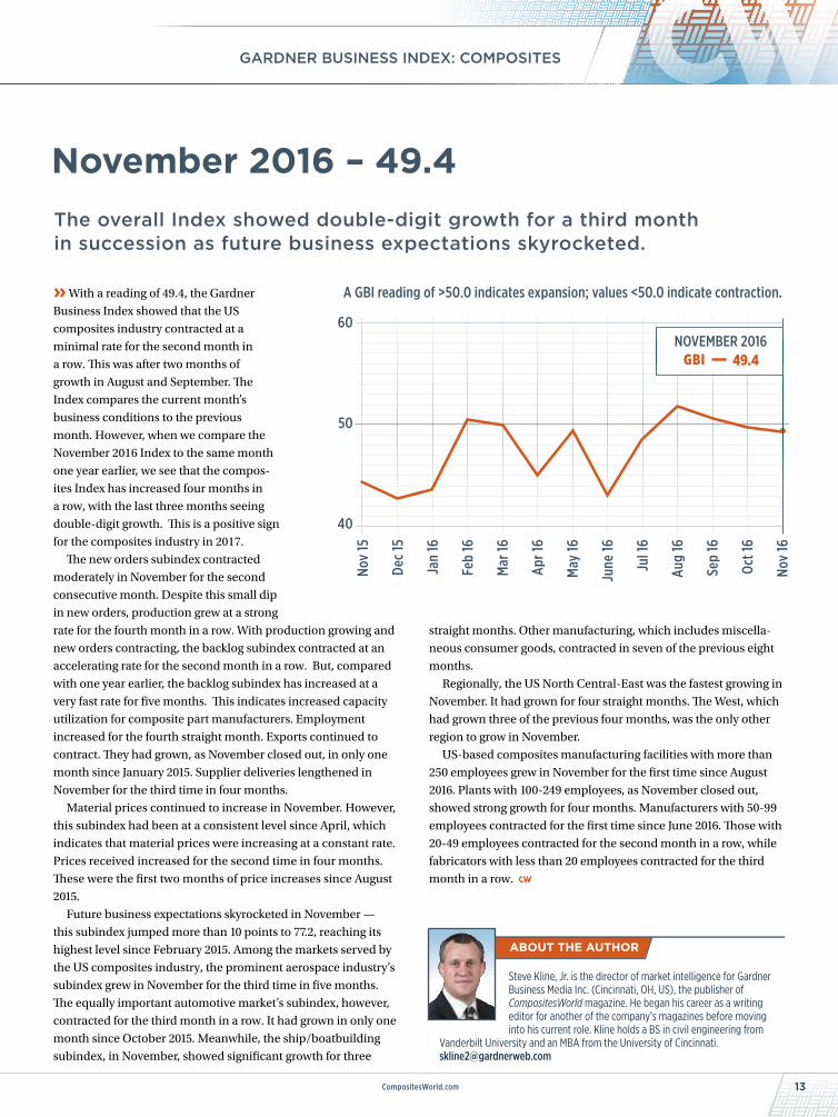
The overall Index showed double-digit growth for a third month in succession as future business expectations skyrocketed.
CompositesWorld.com
» With a reading of 49.4, the Gardner
Business Index showed that the US
composites industry contracted at a
minimal rate for the second month in
a row. This was after two months of
growth in August and September. The
Index compares the current month’s
business conditions to the previous
month. However, when we compare the
November 2016 Index to the same month
one year earlier, we see that the compos-
ites Index has increased four months in
a row, with the last three months seeing
double-digit growth. This is a positive sign
for the composites industry in 2017.
The new orders subindex contracted
moderately in November for the second
consecutive month. Despite this small dip
in new orders, production grew at a strong
rate for the fourth month in a row. With production growing and
new orders contracting, the backlog subindex contracted at an
accelerating rate for the second month in a row. But, compared
with one year earlier, the backlog subindex has increased at a
very fast rate for five months. This indicates increased capacity
utilization for composite part manufacturers. Employment
increased for the fourth straight month. Exports continued to
contract. They had grown, as November closed out, in only one
month since January 2015. Supplier deliveries lengthened in
November for the third time in four months.
Material prices continued to increase in November. However,
this subindex had been at a consistent level since April, which
indicates that material prices were increasing at a constant rate.
Prices received increased for the second time in four months.
These were the first two months of price increases since August
2015.
Future business expectations skyrocketed in November —
this subindex jumped more than 10 points to 77.2, reaching its
highest level since February 2015. Among the markets served by
the US composites industry, the prominent aerospace industry’s
subindex grew in November for the third time in five months.
The equally important automotive market’s subindex, however,
contracted for the third month in a row. It had grown in only one
month since October 2015. Meanwhile, the ship/boatbuilding
subindex, in November, showed significant growth for three
straight months. Other manufacturing, which includes miscella-
neous consumer goods, contracted in seven of the previous eight
months.
Regionally, the US North Central-East was the fastest growing in
November. It had grown for four straight months. The West, which
had grown three of the previous four months, was the only other
region to grow in November.
US-based composites manufacturing facilities with more than
250 employees grew in November for the first time since August
2016. Plants with 100-249 employees, as November closed out,
showed strong growth for four months. Manufacturers with 50-99
employees contracted for the first time since June 2016. Those with
20-49 employees contracted for the second month in a row, while
fabricators with less than 20 employees contracted for the third
month in a row.
November 2016 – 49.4
Steve Kline, Jr. is the director of market intelligence for Gardner Business Media Inc. (Cincinnati, OH, US), the publisher of CompositesWorld magazine. He began his career as a writing editor for another of the company’s magazines before moving into his current role. Kline holds a BS in civil engineering from
Vanderbilt University and an MBA from the University of Cincinnati. [email protected]
60
50
40
A GBI reading of >50.0 indicates expansion; values <50.0 indicate contraction.
Nov
15
Dec
15
Jan
16
Feb
16
Mar
16
Apr 1
6
May
16
June
16
Jul 1
6
Aug
16
Sep
16
Oct 1
6
Nov
16
49.4GBINOVEMBER 2016
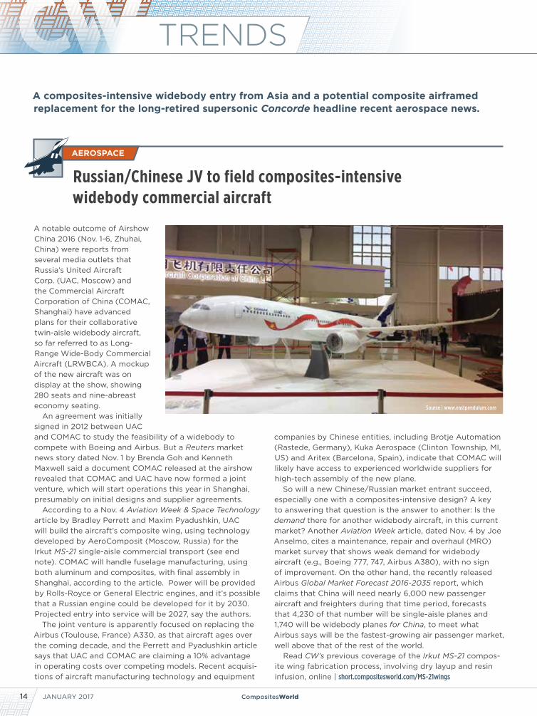
A composites-intensive widebody entry from Asia and a potential composite airframed replacement for the long-retired supersonic Concorde headline recent aerospace news.
JANUARY 201714 CompositesWorld
TRENDS
A notable outcome of Airshow China 2016 (Nov. 1-6, Zhuhai, China) were reports from several media outlets that Russia’s United Aircraft Corp. (UAC, Moscow) and the Commercial Aircraft Corporation of China (COMAC, Shanghai) have advanced plans for their collaborative twin-aisle widebody aircraft, so far referred to as Long-Range Wide-Body Commercial Aircraft (LRWBCA). A mockup of the new aircraft was on display at the show, showing 280 seats and nine-abreast economy seating.
An agreement was initially signed in 2012 between UAC and COMAC to study the feasibility of a widebody to compete with Boeing and Airbus. But a Reuters market news story dated Nov. 1 by Brenda Goh and Kenneth Maxwell said a document COMAC released at the airshow revealed that COMAC and UAC have now formed a joint venture, which will start operations this year in Shanghai, presumably on initial designs and supplier agreements.
According to a Nov. 4 Aviation Week & Space Technology article by Bradley Perrett and Maxim Pyadushkin, UAC will build the aircraft’s composite wing, using technology developed by AeroComposit (Moscow, Russia) for the Irkut MS-21 single-aisle commercial transport (see end note). COMAC will handle fuselage manufacturing, using both aluminum and composites, with final assembly in Shanghai, according to the article. Power will be provided by Rolls-Royce or General Electric engines, and it’s possible that a Russian engine could be developed for it by 2030. Projected entry into service will be 2027, say the authors.
The joint venture is apparently focused on replacing the Airbus (Toulouse, France) A330, as that aircraft ages over the coming decade, and the Perrett and Pyadushkin article says that UAC and COMAC are claiming a 10% advantage in operating costs over competing models. Recent acquisi-tions of aircraft manufacturing technology and equipment
companies by Chinese entities, including Brotje Automation (Rastede, Germany), Kuka Aerospace (Clinton Township, MI, US) and Aritex (Barcelona, Spain), indicate that COMAC will likely have access to experienced worldwide suppliers for high-tech assembly of the new plane.
So will a new Chinese/Russian market entrant succeed, especially one with a composites-intensive design? A key to answering that question is the answer to another: Is the demand there for another widebody aircraft, in this current market? Another Aviation Week article, dated Nov. 4 by Joe Anselmo, cites a maintenance, repair and overhaul (MRO) market survey that shows weak demand for widebody aircraft (e.g., Boeing 777, 747, Airbus A380), with no sign of improvement. On the other hand, the recently released Airbus Global Market Forecast 2016-2035 report, which claims that China will need nearly 6,000 new passenger aircraft and freighters during that time period, forecasts that 4,230 of that number will be single-aisle planes and 1,740 will be widebody planes for China, to meet what Airbus says will be the fastest-growing air passenger market, well above that of the rest of the world.
Read CW’s previous coverage of the Irkut MS-21 compos-ite wing fabrication process, involving dry layup and resin infusion, online | short.compositesworld.com/MS-21wings
Russian/Chinese JV to field composites-intensive widebody commercial aircraft
AEROSPACE
Source | www.eastpendulum.com
CompositesWorld.com 15
TRENDS
ENERGY
In the wake of November 2016’s US presidential election, Wired editorialist Nick Stockton argued in an opinion piece that, “America’s Brief Role as a Climate Leader is Probably Over.” Stockton contended on Nov. 9, as climate negotia-tors and a crowd of NGOs, journalists, and other observers from 200 countries gathered in Marrakesh, Morroco to work on the details of the Paris climate change agreement, that although president-elect “Trump hasn’t described his climate and energy policies in detail, he has made it clear that he will not honor promises the Obama administration made to combat the intensifying global warming catas-trophe.” He went on to say, “Trump has called the Paris agreement a bad deal, vowing to pull out or renegotiate the US commitment.” Further, Trump’s stated commit-ment to protect internal US development and manufac-turing activity is likely to result in the imposition of tariffs on the imported equipment and technologies that have, thus far, helped make renewable energy alternatives in the US, including wind power generation, competitive with domestic coal-fired electrical plants. “Tariffs would make
those components more expensive,” said Stockton, “and that added cost could get passed along to consumers. So goes renewable energy’s competitiveness with fossil fuels.”
But Dan Woynillowicz, policy director, and Merran Smith, executive director of Clean Energy Canada, a national climate and energy think tank based north of the US border at Simon Fraser University’s Centre for Dialogue (Vancouver, BC, Canada), in an opinion piece that appeared Nov. 14 in The Globe and Mail (Toronto, ON, Canada), told a somewhat different story. Although they acknowledged that stock prices for clean-energy companies plummeted not only in the US but in Canada as well in the wake of the Trump victory, and that there is no question that Trump and Clinton differed significantly on the issue of climate change and the opportunities that clean energy technolo-gies offer, the “reality is that clean energy has been boom-ing in the United States for a whole bunch of reasons that don’t have much to do with climate change. Things such as health, security and innovation, which lead to high levels of support amongst Republicans — yes,
US wind energy prospects under Trump: Industry opinion divided
(Continued on p. 16)
TRENDS
JANUARY 201716 CompositesWorld
(Continued from p. 15)
Republicans — for harnessing the power of American water, wind and sun.”
Those federal tax credits for wind and solar energy projects? They were passed in December 2015 by a Republican-dominated Congress with bipartisan support. Revoking them now would require a legislative effort that might not be looked upon kindly by the many Republican lawmakers who have renewable energy manufacturing and development operations located in their states. In fact, 80% of installed wind energy proj-ects, for example, are situated in Republican-governed districts.
Similar reasoning has prompted the American Wind Energy Assn. (AWEA, Washington, DC, US), to adopt a watchful, indeed, a rather hopeful, post-election stance. In his AWEA Blog, titled Into the Wind, AWEA CEO Tom Kiernan wrote on Nov. 9, the morning after the election,
“The American Wind Energy Assn. is ready to work with President-elect Donald Trump and his administration to assure that wind power continues to be a vibrant part of the U.S. economy.
“Mr. Trump has said, ‘We can pursue all forms of energy. This includes renewable energies and the technologies of the future.’ We look forward to working with him and his appointees to make sure they recognize that wind is working very well in America today as a mainstream energy source.”
Kiernan added. “In his victory speech early this morn-ing, the President-elect said, ‘We’re going to rebuild our infrastructure, which will become, by the way, second to none. And we will put millions of our people to work as we rebuild it.’ Wind power is some of the best infra-structure America has ever built and we are on track to doubling it from today’s levels by 2020.”
Kiernan went on to say that the 2016 Republican Party’s electoral platform backed the sort of grid trans-mission development that continued wind energy devel-opment requires, quoting: “‘We support expedited siting processes and the thoughtful expansion of the grid so that consumers and businesses continue to have access to affordable and reliable electricity.’”
Further, Dan Reicher, executive director of the Streyer-Taylor Center for Energy Policy and Finance at Stanford Law School (San Diego, CA, US), told UtilityDIVE columnist Peter Maloney (UltilityDive.com) that despite the fact that both houses of the US Congress now will be under Republican control, it is unlikely there will be a move to repeal the previously much debated produc-tion tax credit (PTC) for wind power development. There is limited incentive to do so, he argues, because it was renewed in December 2015, with built-in reductions on a stepped-down basis, and with definitive expiration dates in 2020. At the beginning of 2017, for example, the PTC drops to 80% of current, so the step-down schedule also offers the incentive for developers of wind projects in particular to push to close financing on their projects sooner rather than later.
Trump’s true impact on wind is, of course, in the wind.
17CompositesWorld.com
NEWSCW Month in Review
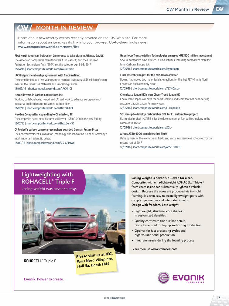
Losing weight is never fun – even for a car.Composites with ultra-lightweight ROHACELL® Triple F foam cores inside can substantially lighten a vehicle design. Because the cores are produced via in-mold foaming, it‘s even easy to create lightweight parts with complex geometries and integrated inserts. Design with freedom. Lose weight.
• Lightweight, structural core shapes – in customized densities• Quality cores with fi ne surface details, ready to be used for lay-up and curing production• Optimal for fast processing cycles and high volume serial production• Integrate inserts during the foaming process
Learn more at www.rohacell.com
Please visit us at JEC,
Paris Nord Villepinte,
Hall 5a, Booth H44
Lightweighting with ROHACELL® Triple FLosing weight was never so easy.
Notes about newsworthy events recently covered on the CW Web site. For more information about an item, key its link into your browser. Up-to-the-minute news | www.compositesworld.com/news/list
MONTH IN REVIEW
First North American Pultrusion Conference to take place in Atlanta, GA, USThe American Composites Manufacturers Assn. (ACMA) and the European Pultrusion Technology Assn (EPTA) set the dates for April 4-5, 2017.12/14/16 | short.compositesworld.com/NAPultrude
IACMI signs membership agreement with Cincinnati Inc.The commitment as a five-year resource member leverages US$3 million of equip-ment at the Tennessee Materials and Processing Center.12/012/16 | short.compositesworld.com/IACMI-CI
Hexcel invests in Carbon Conversions Inc.Working collaboratively, Hexcel and CCI will work to advance aerospace and industrial applications for reclaimed carbon fiber.12/12/16 | short.compositesworld.com/Hexcel-CCI
NexGen Composites expanding to Charleston, SCThe composite panel manufacturer will invest US$100,000 in the new facility.12/12/16 | short.compositesworld.com/NextGen-SC
C3 Project’s carbon concrete researchers awarded German Future PrizeThe Federal President’s Award for Technology and Innovation is one of Germany’s most important scientific prizes. 12/09/16 | short.compositesworld.com/C3-GFPawd
Hyperloop Transportation Technologies amasses >US$100 million investmentSeveral companies have offered in-kind services, including composites manufac-turer Carbures Europe SA.12/05/16 | short.compositesworld.com/Hyperloop
Final assembly begins for the 787-10 DreamlinerBoeing has moved two major fuselage sections for the first 787-10 to its North Charleston final assembly plant.12/05/16 | short.compositesworld.com/787-10asby
Chemlease Japan KK is now Chem-Trend Japan KKChem-Trend Japan will have the same location and team that has been serving customers across Japan for many years.12/05/16 | short.compositesworld.com/C-TJapanKK
SGL Group to develop carbon fiber GDL for EU automotive projectEU-funded project INSPIRE is for the development of fuel cell technology in the automotive sector.12/05/16 | short.compositesworld.com/SGL-
Airbus A350-1000 completes first flightDevelopment of the aircraft is on track, and entry into service is scheduled for the second half of 2017.12/02/16 | short.compositesworld.com/A350-10001

SUBSCRIBE TODAY. compositesworld.com
CW is CompositesWorld!
CW Subscribe Today.indd 1 12/20/16 3:03 PM
19CompositesWorld.com
NEWSChina’s Glass Fiber Giant in US
www.northcoast.us216-398-8550
North Coast is excited to announce that we are joining
the AGC AeroComposites family giving us
the ability to offer greater capabilities,
increased capacity, and ability to provide
a wider array of technical solutions.
With over 40 years in the business,
let us be your guide: - design and engineering - tooling and mold development - machining and parts production
We are expanding our horizons
Jushi Group (Zhejiang, China), the largest manufacturer of glass fiber in the world, with a production capacity of more than 1 million MT per year, is putting down production roots on US soil. The company operates three manufacturing sites in its home territory, and opened a fourth (its first overseas) in Egypt in 2014, to more directly supply Europe and the Middle East. Like the site in Egypt, the new US facility will add 80,000 MT/yr of capacity in its Phase I development.
Located in the Pineview Industrial Park, outside of Columbia, SC, construction of the US $300 million plant is slated to begin in first-quarter 2017 and be completed by year-end 2018. Jushi USA will then relocate its headquarters to that site from its current location in Irwindale, CA.
Drew Walker, previously president of high-strength glass fiber producer AGY (Aiken, SC, US), is now president and general manager of the new Jushi USA plant. He said the plant’s location offers a skilled workforce and excel-lent logistics — an adjacent rail line for raw materials and proximity to major north/south and east/west highways for shipping products, as well as connection to the seaport of Charleston. Many weavers and textile producers also are located in the state and the South Carolina Department of Commerce has had an office in Beijing for years.
“Of course South Carolina offers incentives,” says Walker, “but its Chinese delegation was also very important. They have developed a good relationship and have been able
China Jushi USA breaks ground on 80,000-MT glass fiber facility
to address Jushi’s concerns.” Walker adds that Jushi has the most advanced technology worldwide for glass fiber production. Indeed, the company’s 2014 announcement of its E7 high-strength fiber claims a 30% increase in tensile strength and 11% increase in modulus vs. previous boron-free high-strength products when tested in unidirectional fabrics for wind blades. The same technology adapted as 312T roving for pultrusion provides a 15% boost in tensile strength with 10% higher modulus. This is report-edly achieved while being boron- and fluorine-free, using advanced melting techniques such as oxygen firing technol-ogy to reduce emissions (waste gas by 80%, nitrogen oxide by 90%) and employing recycling to achieve zero discharge of industrial wastewater. Information on-site at the ground-breaking stated that the new SC plant will feature informa-tion technology-integrated smart machinery and intelligent manufacturing control.
Jushi Group president Yang Guoming said that America is where fiberglass was created and was once the larg-est fiberglass producing nation, but now is Jushi’s larg-est market. This South Carolina facility, he continued, is evidence of “our determination to be further globalized, first creating markets and then supporting them locally. In 1995 our products entered the US market,” said Yang. “We are now exporting capital and want to work with the US to promote the fiberglass industry and market.”
TRENDS
JANUARY 201720 CompositesWorld
Walton Process Technologies, Inc.
Best Customer Service in The Industrywww.autoclaves.com
Mansfield TX 682-518-9002
Service/Repair
Retrofit/Relocate
Autoclaves
Bond Presses
Batch ProcessControls
Ovens
Parts
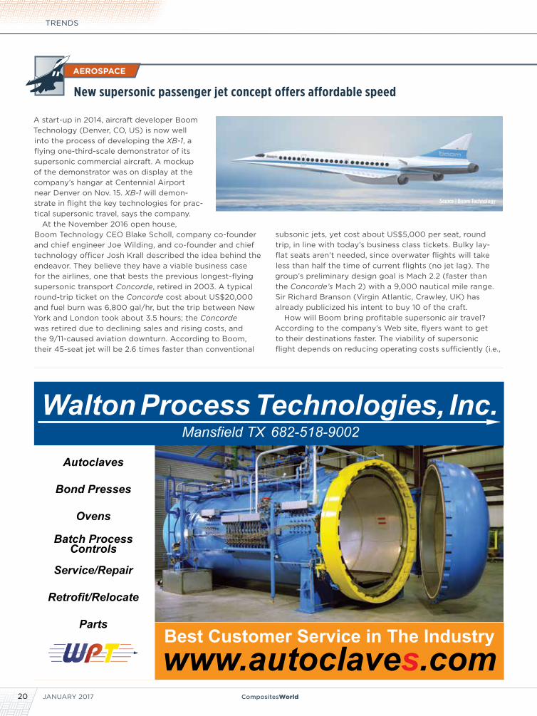
A start-up in 2014, aircraft developer Boom Technology (Denver, CO, US) is now well into the process of developing the XB-1, a flying one-third-scale demonstrator of its supersonic commercial aircraft. A mockup of the demonstrator was on display at the company’s hangar at Centennial Airport near Denver on Nov. 15. XB-1 will demon-strate in flight the key technologies for prac-tical supersonic travel, says the company.
At the November 2016 open house, Boom Technology CEO Blake Scholl, company co-founder and chief engineer Joe Wilding, and co-founder and chief technology officer Josh Krall described the idea behind the endeavor. They believe they have a viable business case for the airlines, one that bests the previous longest-flying supersonic transport Concorde, retired in 2003. A typical round-trip ticket on the Concorde cost about US$20,000 and fuel burn was 6,800 gal/hr, but the trip between New York and London took about 3.5 hours; the Concorde was retired due to declining sales and rising costs, and the 9/11-caused aviation downturn. According to Boom, their 45-seat jet will be 2.6 times faster than conventional
subsonic jets, yet cost about US$5,000 per seat, round trip, in line with today’s business class tickets. Bulky lay-flat seats aren’t needed, since overwater flights will take less than half the time of current flights (no jet lag). The group’s preliminary design goal is Mach 2.2 (faster than the Concorde’s Mach 2) with a 9,000 nautical mile range. Sir Richard Branson (Virgin Atlantic, Crawley, UK) has already publicized his intent to buy 10 of the craft.
How will Boom bring profitable supersonic air travel? According to the company’s Web site, flyers want to get to their destinations faster. The viability of supersonic flight depends on reducing operating costs sufficiently (i.e.,
AEROSPACE
New supersonic passenger jet concept offers affordable speed
Source | Boom Technology
21CompositesWorld.com
NEWSConcorde’s Replacement?
lower fuel burn) coupled with reasonable fares travelers are willing to pay for the speed; this requires just a 30% efficiency improvement over Concorde’s airframe and engines, with composite materials playing a role, says the company. With more than 1,000 simulated wind tunnel tests already done, three major innovations are an area-ruled fuselage (the aft cabin will be tapered to reduce cross-section), a chine or wing extension towards the nose to help balance and control at supersonic speeds, and a refined delta wing with a swept trailing edge that reduces supersonic drag and quiets the sonic boom.
Carbon fiber composites will be used throughout the airframe, for lighter weight and to counteract the signifi-cant growth and expansion that the Concorde’s aluminum design experienced in flight. The XB-1 will be powered by three General Electric engines with shaped variable geom-etry inlets. Acknowledging that a ban on supersonic flights still exists over the US, the company says the jet will begin with overwater routes, such as New York to London or San Francisco to Toyko. The sonic boom from a Boom jet will reportedly be much quieter than the Concorde’s. Boom Technology says that its XB-1 will begin test flights in late 2017, in Colorado, then move to Edwards AFB in California.
Watch a video explaining Boom Technology’s vision |boomsupersonic.com
Get a behind-the-scenes look at the XB-1 | boomsupersonic.com/xb-1
BIZ BRIEF
Mafic USA, a unit of Mafic Inc. (Woodbridge, ON, Canada), will invest US$15 million in a new produc-tion facility located in Shelby, NC, US. The company’s new operations in Shelby will employ about 113 skilled operators, engineers, sales staff and other personnel.
A global producer of continuous and chopped basalt fiber as well as long fiber thermoplastic resins, Mafic ships products to buyers in the auto-motive, aerospace, alternative energy and other industries. The company currently produces its basalt fiber products in Ireland and its long-fiber thermoplastic resins in Canada.
“We considered a number of locations across the US for our first American manufacturing facility, said Mafic CEO Mike Levine. “North Carolina and Cleveland County had been under consideration from the start, due to its network of specialized suppliers and wide range of potential B2B custom-ers and strategic partners. What sealed the deal for us was the multifaceted support from all levels of government; the state, county and city. In particu-lar, the Cleveland County Economic Development Partnership went way beyond what was expected.”
[email protected] • 865.686.5670 • mvpind.com
Adhesive Processing MAde siMPle Providing Innovative Dispensing Solutions for Over 40 Years
• Efficientprocessingofpolyurethane,epoxy,polyester, andotheradhesives
• Highlyaccuratedispensingandsprayingsystems
• Ergonomicdesignanduser-friendlycontrols
• Idealforroboticapplications
• Durablestainlesssteelstructure
• Streamlinedmaintenancesavestimeandmoney
innovative. simple. reliable.
[email protected] • mvpind.com
ADHESIVE PROCESSINGMADE SIMPLEProviding Innovative Dispensing Solutions for Over 40 Years
Ideal for robotic applications
Durable stainless steel structure
Streamlined maintenance saves time and money
Efficient processing of polyurethane, epoxy, polyester, and other adhesives
Highly accurate dispensing and spraying systems
Ergonomic design and user-friendly controls
Innovative. Simple. Reliable. | [email protected] | www.mvpind.comCOME SEE US ATJEC 2017 BOOTH U42!
TRENDS
JANUARY 201722 CompositesWorld
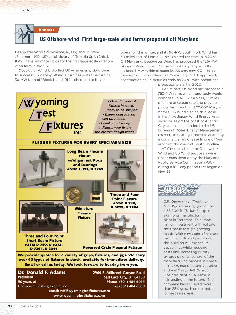
Deepwater Wind (Providence, RI, US) and US Wind (Baltimore, MD, US), a subsidiary of Renexia SpA (Chieti, Italy), have submitted bids for the first large-scale offshore wind farm in the US.
Deepwater Wind is the first US wind energy developer to successfully deploy offshore turbines — its five-turbine, 30-MW farm off Block Island, RI is scheduled to begin
US Offshore wind: First large-scale wind farms proposed off Maryland
operation this winter, and its 90-MW South Fork Wind Farm 30 miles east of Montauk, NY is slated for startup in 2022. Off Maryland, Deepwater Wind has proposed the 120-MW Skipjack Wind Farm — 20 turbines if they stay with the Heliade 6 MW turbines made by Alstom, now GE — to be located 17 miles northeast of Ocean City, MD. If approved, construction could begin as early as 2020, with operations
projected to start in 2022.For its part, US Wind has proposed a
750-MW farm, which reportedly would comprise up to 187 turbines, 12 miles offshore of Ocean City and provide power for more than 500,000 Maryland homes. US Wind also holds a lease in the New Jersey Wind Energy Area, seven miles off the coast of Atlantic City, and has responded to the US Bureau of Ocean Energy Management (BOEM), indicating interest in acquiring a commercial wind lease in one of four areas off the coast of South Carolina.
AT CW press time, the Deepwater Wind and US Wind proposals were under consideration by the Maryland Public Service Commission (PSC), during a 180-day period that began on Nov. 28.
ENERGY
WTF
yomingest
ixturesINC.
• Over 40 types of fixtures in stock, ready to be shipped. • Expert consultation with Dr. Adams • Email or call today to discuss your fixture and custom design needs.
Three and Four Point Short Beam FixtureASTM D 790, D 6272,
D 7264, D 2344
2960 E. Millcreek Canyon RoadSalt Lake City, UT 84109
Phone (801) 484.5055Fax (801) 484.6008
email: [email protected]
Dr. Donald F. AdamsPresident50 years of Composite Testing Experience
FLEXURE FIXTURES FOR EVERY SPECIMEN SIZE
We provide quotes for a variety of grips, fixtures, and jigs. We carry over 40 types of fixtures in stock, available for immediate delivery.
Email or call us today. We look forward to hearing from you.
Three and Four Point FlexureASTM D 790,
D 6272, D 7264
Long Beam Flexure Fixture
w/Alignment Rods and Bearings
ASTM C 393, D 7249
Reversed Cycle Flexural Fatigue
Miniature Flexure Fixture
BIZ BRIEF
C.R. Onsrud Inc. (Troutman, NC, US) is breaking ground on a 55,000-ft2 (5,110m2) expan-sion to its manufacturing plant in Troutman. This US$8 million investment will facilitate the Onsrud family’s growing needs. With new state-of-the-art machine tools and processes, this building will expand its capabilities while reducing costs and increasing quality by providing full control of the manufacturing process in-house.
“Yes US manufacturing is alive and well,” says Jeff Onsrud, vice president. “C.R. Onsrud is investing in the future.” The company has achieved more than 25% growth compared to its best sales year.
23CompositesWorld.com
NEWS
The automotive industry is on the brink of a materials revolution. So say the owners of Connora Technologies (Hayward, CA, US), who believe that their recyclable thermoset resin technology could be the tipping point.
Awarded Phase II funding in October 2016 in the amount of US$730,000 by the National Science Foundation’s Small Business Innovation Research (SBIR) program, Connora, led by CEO, Dr. Rey Banatao and CTO, Dr. Stefan Pastine, says it is poised to launch its new class of recyclable high-performance composites from the laboratory into the high volume automotive market and beyond. Connora’s focus is to enable cost-effective, efficient manufacture of recyclable thermoset composites.
Already used extensively throughout the transportation, aerospace, consumer electronics, civil engineering and sporting goods industries, where superior strength/weight ratios, rigidity, durability and corrosion resistance are prized attributes, thermoset resins have replaced aluminum and steel in many markets despite the material’s inherent drawbacks: thermoset composites are currently expensive, slow to produce and intrinsically difficult to repair or recycle. Connora’s SBIR Project aims to address these limitations by further developing Recyclamine resins for HP-RTM (high-pressure resin transfer molding) applications in automotive applications.
Where other approaches reduce the reclaimed fiber performance and value of the composites, Connora’s recycling approach reportedly preserves the virgin performance and value of the reclaimed fibers and reclaims the thermoset resin as a high value, reusable thermoplastic resin.
For more on Recyclamine | short.compositesworld.com/connoraRTM
Connora awarded US$730,000 for SBIR Phase IIBIZ BRIEFS
Gurit (Zurich, Switzerland) has acquired BASF SE’s (Ludwigshaven, Germany) polyethylene terephthalate (PET) structural foam business, which includes BASF’s PET operations in Volpiano, Italy, including its staff, operating assets and product IP in the form of an asset deal. This acquisition is expected to strengthen Gurit’s structural core material product range and add a sizable European-based PET production capacity to the company’s existing PET operations in mainland China. The BASF Kerdyn product brand will reinforce Gurit’s PET product offering to the wind, marine, transport and construc-tion industry. Additionally, Gurit will gain significant extru-sion process technology and product innovation know-how. BASF had previously purchased the PET foam business in Volpiano from B.C. Foam SpA. Gurit intends to integrate and further develop its new PET operations as part of its composite materials business unit.
“We would like to welcome the BASF team in Volpiano to Gurit and look forward to dynamically developing the site and business together,” says Gurit CEO Rudolf Hadorn.
Plasmatreat North America (Elgin, IL, US) opened its new West Coast facility in Hayward, CA, US, a location able to accommodate more equipment and offering more space to help customers run trials, develop new processes, help educate the market about plasma technology and to provide contract surface treatment services for those who wish to take advantage of the benefits of plasma before purchasing systems for their own use.
Engineering Services Complex Shapes 5 Axis NC Milling Large Facilities High-Precision Equipment
SHIP BUILDING
WIND ENERGY
www.janicki.com360.856.5143
TRANSPORTATION
AEROSPACE
Funding for Recyclable Thermoset
JANUARY 201724 CompositesWorld
Carbon Fiber 2016 ReportConference speakers predict the outlook for carbon fiber supply and demand.
» CompositesWorld’s annual Carbon Fiber Conference, Nov.
9-11 in Scottsdale, AZ, US, offered its usual insightful look at the
current and anticipated application of carbon fiber composites
in a variety of markets and products. The opening session kicked
off with a seminar presented by Chris Red
of Composites Forecasts and Consulting
LLC (Mesa AZ, US) on the global outlook
for carbon fibers and carbon fiber
composites. As usual, Chris included his
assessment of carbon fiber supply and
demand — this time, through 2025.
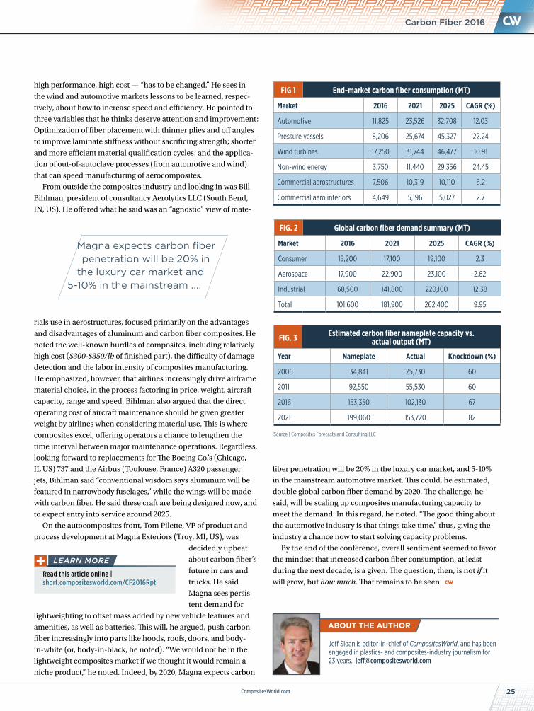
In terms of consumption by volume,
Red noted that the vast majority (75%)
of carbon fiber is used in the industrial
market, which includes the automotive,
pressure vessels and wind energy sectors.
The remainder goes to the aerospace
market (14%) and the consumer
market (11%).
The biggest drivers of carbon fiber use
over the coming decade, says Red, will
be in categories he labels automotive,
pressure vessels, wind turbines, non-wind
energy, commercial aerospace structures
and commercial aero interiors. His outlook
for these is charted in Fig. 1, p. 25.
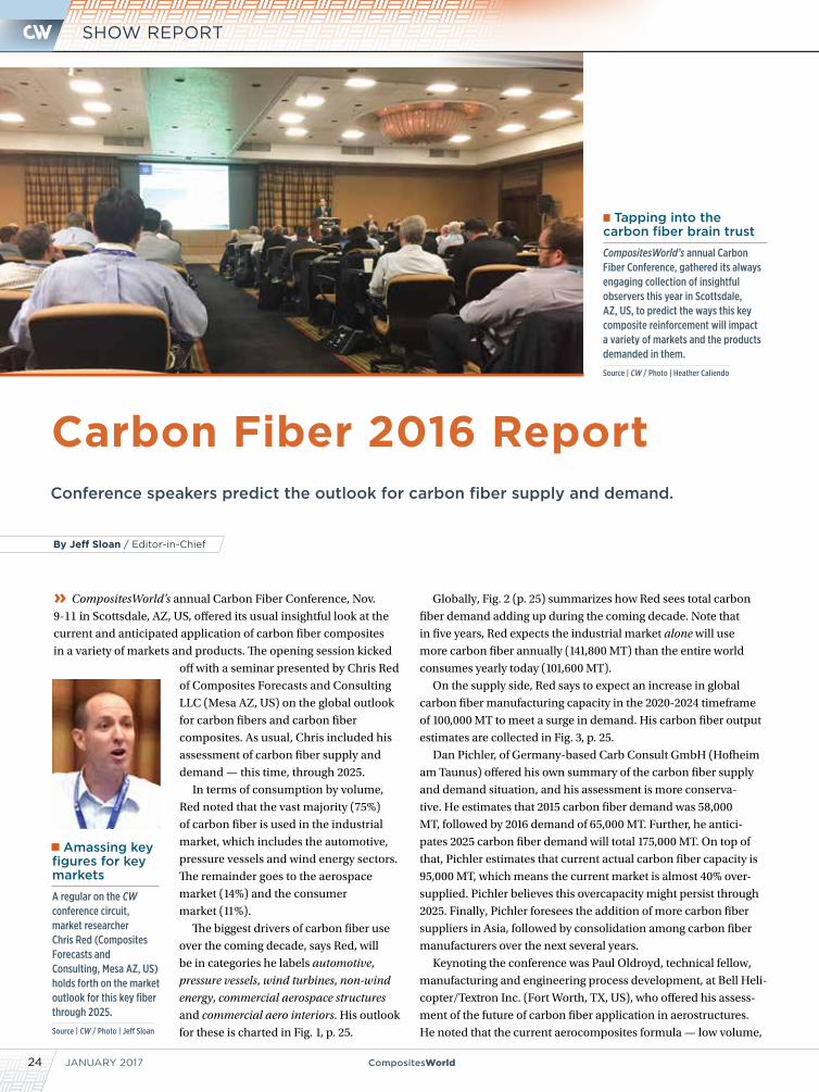
Tapping into the carbon fiber brain trust
CompositesWorld’s annual Carbon Fiber Conference, gathered its always engaging collection of insightful observers this year in Scottsdale, AZ, US, to predict the ways this key composite reinforcement will impact a variety of markets and the products demanded in them.
Source | CW / Photo | Heather Caliendo
Globally, Fig. 2 (p. 25) summarizes how Red sees total carbon
fiber demand adding up during the coming decade. Note that
in five years, Red expects the industrial market alone will use
more carbon fiber annually (141,800 MT) than the entire world
consumes yearly today (101,600 MT).
On the supply side, Red says to expect an increase in global
carbon fiber manufacturing capacity in the 2020-2024 timeframe
of 100,000 MT to meet a surge in demand. His carbon fiber output
estimates are collected in Fig. 3, p. 25.
Dan Pichler, of Germany-based Carb Consult GmbH (Hofheim
am Taunus) offered his own summary of the carbon fiber supply
and demand situation, and his assessment is more conserva-
tive. He estimates that 2015 carbon fiber demand was 58,000
MT, followed by 2016 demand of 65,000 MT. Further, he antici-
pates 2025 carbon fiber demand will total 175,000 MT. On top of
that, Pichler estimates that current actual carbon fiber capacity is
95,000 MT, which means the current market is almost 40% over-
supplied. Pichler believes this overcapacity might persist through
2025. Finally, Pichler foresees the addition of more carbon fiber
suppliers in Asia, followed by consolidation among carbon fiber
manufacturers over the next several years.
Keynoting the conference was Paul Oldroyd, technical fellow,
manufacturing and engineering process development, at Bell Heli-
copter/Textron Inc. (Fort Worth, TX, US), who offered his assess-
ment of the future of carbon fiber application in aerostructures.
He noted that the current aerocomposites formula — low volume,
By Jeff Sloan / Editor-in-Chief
Amassing key figures for key markets
A regular on the CW conference circuit, market researcher Chris Red (Composites Forecasts and Consulting, Mesa AZ, US) holds forth on the market outlook for this key fiber through 2025.
Source | CW / Photo | Jeff Sloan
SHOW REPORT
25CompositesWorld.com
high performance, high cost — “has to be changed.” He sees in
the wind and automotive markets lessons to be learned, respec-
tively, about how to increase speed and efficiency. He pointed to
three variables that he thinks deserve attention and improvement:
Optimization of fiber placement with thinner plies and off angles
to improve laminate stiffness without sacrificing strength; shorter
and more efficient material qualification cycles; and the applica-
tion of out-of-autoclave processes (from automotive and wind)
that can speed manufacturing of aerocomposites.
From outside the composites industry and looking in was Bill
Bihlman, president of consultancy Aerolytics LLC (South Bend,
IN, US). He offered what he said was an “agnostic” view of mate-
rials use in aerostructures, focused primarily on the advantages
and disadvantages of aluminum and carbon fiber composites. He
noted the well-known hurdles of composites, including relatively
high cost ($300-$350/lb of finished part), the difficulty of damage
detection and the labor intensity of composites manufacturing.
He emphasized, however, that airlines increasingly drive airframe
material choice, in the process factoring in price, weight, aircraft
capacity, range and speed. Bihlman also argued that the direct
operating cost of aircraft maintenance should be given greater
weight by airlines when considering material use. This is where
composites excel, offering operators a chance to lengthen the
time interval between major maintenance operations. Regardless,
looking forward to replacements for The Boeing Co.’s (Chicago,
IL US) 737 and the Airbus (Toulouse, France) A320 passenger
jets, Bihlman said “conventional wisdom says aluminum will be
featured in narrowbody fuselages,” while the wings will be made
with carbon fiber. He said these craft are being designed now, and
to expect entry into service around 2025.
On the autocomposites front, Tom Pilette, VP of product and
process development at Magna Exteriors (Troy, MI, US), was
decidedly upbeat
about carbon fiber’s
future in cars and
trucks. He said
Magna sees persis-
tent demand for
lightweighting to offset mass added by new vehicle features and
amenities, as well as batteries. This will, he argued, push carbon
fiber increasingly into parts like hoods, roofs, doors, and body-
in-white (or, body-in-black, he noted). “We would not be in the
lightweight composites market if we thought it would remain a
niche product,” he noted. Indeed, by 2020, Magna expects carbon
Jeff Sloan is editor-in-chief of CompositesWorld, and has been engaged in plastics- and composites-industry journalism for 23 years. [email protected]
FIG 1 End-market carbon fiber consumption (MT)
Market 2016 2021 2025 CAGR (%)
Automotive 11,825 23,526 32,708 12.03
Pressure vessels 8,206 25,674 45,327 22.24
Wind turbines 17,250 31,744 46,477 10.91
Non-wind energy 3,750 11,440 29,356 24.45
Commercial aerostructures 7,506 10,319 10,110 6.2
Commercial aero interiors 4,649 5,196 5,027 2.7
FIG. 2 Global carbon fiber demand summary (MT)
Market 2016 2021 2025 CAGR (%)
Consumer 15,200 17,100 19,100 2.3
Aerospace 17,900 22,900 23,100 2.62
Industrial 68,500 141,800 220,100 12.38
Total 101,600 181,900 262,400 9.95
FIG. 3 Estimated carbon fiber nameplate capacity vs. actual output (MT)
Year Nameplate Actual Knockdown (%)
2006 34,841 25,730 60
2011 92,550 55,530 60
2016 153,350 102,130 67
2021 199,060 153,720 82
Source | Composites Forecasts and Consulting LLC
fiber penetration will be 20% in the luxury car market, and 5-10%
in the mainstream automotive market. This could, he estimated,
double global carbon fiber demand by 2020. The challenge, he
said, will be scaling up composites manufacturing capacity to
meet the demand. In this regard, he noted, “The good thing about
the automotive industry is that things take time,” thus, giving the
industry a chance now to start solving capacity problems.
By the end of the conference, overall sentiment seemed to favor
the mindset that increased carbon fiber consumption, at least
during the next decade, is a given. The question, then, is not if it
will grow, but how much. That remains to be seen.
Magna expects carbon fiber penetration will be 20% in
the luxury car market and 5-10% in the mainstream ....
Carbon Fiber 2016
Read this article online | short.compositesworld.com/CF2016Rpt
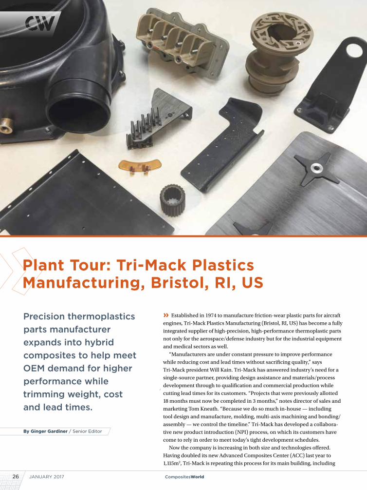
JANUARY 201726 CompositesWorld
Precision thermoplastics parts manufacturer expands into hybrid composites to help meet OEM demand for higher performance while trimming weight, cost and lead times.
» Established in 1974 to manufacture friction-wear plastic parts for aircraft
engines, Tri-Mack Plastics Manufacturing (Bristol, RI, US) has become a fully
integrated supplier of high-precision, high-performance thermoplastic parts
not only for the aerospace/defense industry but for the industrial equipment
and medical sectors as well.
“Manufacturers are under constant pressure to improve performance
while reducing cost and lead times without sacrificing quality,” says
Tri-Mack president Will Kain. Tri-Mack has answered industry’s need for a
single-source partner, providing design assistance and materials/process
development through to qualification and commercial production while
cutting lead times for its customers. “Projects that were previously allotted
18 months must now be completed in 3 months,” notes director of sales and
marketing Tom Kneath. “Because we do so much in-house — including
tool design and manufacture, molding, multi-axis machining and bonding/
assembly — we control the timeline.” Tri-Mack has developed a collabora-
tive new product introduction (NPI) process, on which its customers have
come to rely in order to meet today’s tight development schedules.
Now the company is increasing in both size and technologies offered.
Having doubled its new Advanced Composites Center (ACC) last year to
1,115m2, Tri-Mack is repeating this process for its main building, including
By Ginger Gardiner / Senior Editor
Plant Tour: Tri-Mack Plastics Manufacturing, Bristol, RI, US
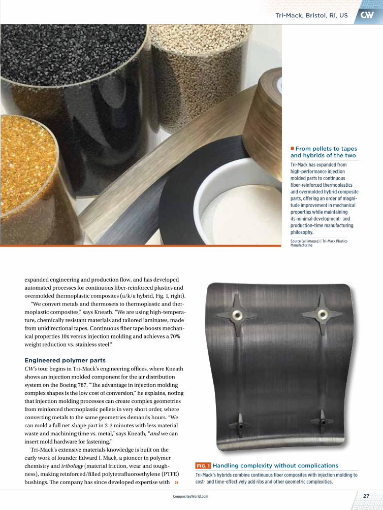
27CompositesWorld.com
NEWSTri-Mack, Bristol, RI, US
expanded engineering and production flow, and has developed
automated processes for continuous fiber-reinforced plastics and
overmolded thermoplastic composites (a/k/a hybrid, Fig. 1, right).
“We convert metals and thermosets to thermoplastic and ther-
moplastic composites,” says Kneath. “We are using high-tempera-
ture, chemically resistant materials and tailored laminates, made
from unidirectional tapes. Continuous fiber tape boosts mechan-
ical properties 10x versus injection molding and achieves a 70%
weight reduction vs. stainless steel.”
Engineered polymer partsCW’s tour begins in Tri-Mack’s engineering offices, where Kneath
shows an injection molded component for the air distribution
system on the Boeing 787. “The advantage in injection molding
complex shapes is the low cost of conversion,” he explains, noting
that injection molding processes can create complex geometries
from reinforced thermoplastic pellets in very short order, where
converting metals to the same geometries demands hours. “We
can mold a full net-shape part in 2-3 minutes with less material
waste and machining time vs. metal,” says Kneath, “and we can
insert mold hardware for fastening.”
Tri-Mack’s extensive materials knowledge is built on the
early work of founder Edward J. Mack, a pioneer in polymer
chemistry and tribology (material friction, wear and tough-
ness), making reinforced/filled polytetrafluoroethylene (PTFE)
bushings. The company has since developed expertise with
From pellets to tapes and hybrids of the twoTri-Mack has expanded from high-performance injection molded parts to continuous fiber-reinforced thermoplastics and overmolded hybrid composite parts, offering an order of magni-tude improvement in mechanical properties while maintaining its minimal development- and production-time manufacturing philosophy.
Source (all images) | Tri-Mack Plastics Manufacturing
FIG. 1 Handling complexity without complications Tri-Mack’s hybrids combine continuous fiber composites with injection molding to cost- and time-effectively add ribs and other geometric complexities.
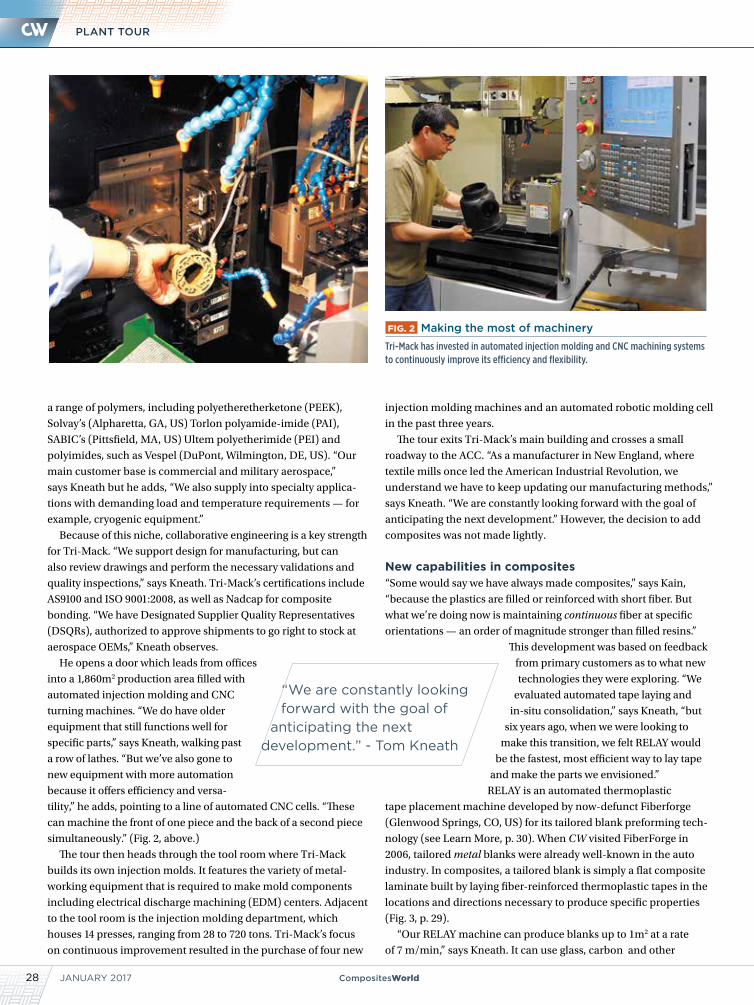
JANUARY 201728 CompositesWorld
PLANT TOUR
injection molding machines and an automated robotic molding cell
in the past three years.
The tour exits Tri-Mack’s main building and crosses a small
roadway to the ACC. “As a manufacturer in New England, where
textile mills once led the American Industrial Revolution, we
understand we have to keep updating our manufacturing methods,”
says Kneath. “We are constantly looking forward with the goal of
anticipating the next development.” However, the decision to add
composites was not made lightly.
New capabilities in composites“Some would say we have always made composites,” says Kain,
“because the plastics are filled or reinforced with short fiber. But
what we’re doing now is maintaining continuous fiber at specific
orientations — an order of magnitude stronger than filled resins.”
This development was based on feedback
from primary customers as to what new
technologies they were exploring. “We
evaluated automated tape laying and
in-situ consolidation,” says Kneath, “but
six years ago, when we were looking to
make this transition, we felt RELAY would
be the fastest, most efficient way to lay tape
and make the parts we envisioned.”
RELAY is an automated thermoplastic
tape placement machine developed by now-defunct Fiberforge
(Glenwood Springs, CO, US) for its tailored blank preforming tech-
nology (see Learn More, p. 30). When CW visited FiberForge in
2006, tailored metal blanks were already well-known in the auto
industry. In composites, a tailored blank is simply a flat composite
laminate built by laying fiber-reinforced thermoplastic tapes in the
locations and directions necessary to produce specific properties
(Fig. 3, p. 29).
“Our RELAY machine can produce blanks up to 1m2 at a rate
of 7 m/min,” says Kneath. It can use glass, carbon and other
FIG. 2 Making the most of machineryTri-Mack has invested in automated injection molding and CNC machining systems to continuously improve its efficiency and flexibility.
a range of polymers, including polyetheretherketone (PEEK),
Solvay’s (Alpharetta, GA, US) Torlon polyamide-imide (PAI),
SABIC’s (Pittsfield, MA, US) Ultem polyetherimide (PEI) and
polyimides, such as Vespel (DuPont, Wilmington, DE, US). “Our
main customer base is commercial and military aerospace,”
says Kneath but he adds, “We also supply into specialty applica-
tions with demanding load and temperature requirements — for
example, cryogenic equipment.”
Because of this niche, collaborative engineering is a key strength
for Tri-Mack. “We support design for manufacturing, but can
also review drawings and perform the necessary validations and
quality inspections,” says Kneath. Tri-Mack’s certifications include
AS9100 and ISO 9001:2008, as well as Nadcap for composite
bonding. “We have Designated Supplier Quality Representatives
(DSQRs), authorized to approve shipments to go right to stock at
aerospace OEMs,” Kneath observes.
He opens a door which leads from offices
into a 1,860m2 production area filled with
automated injection molding and CNC
turning machines. “We do have older
equipment that still functions well for
specific parts,” says Kneath, walking past
a row of lathes. “But we’ve also gone to
new equipment with more automation
because it offers efficiency and versa-
tility,” he adds, pointing to a line of automated CNC cells. “These
can machine the front of one piece and the back of a second piece
simultaneously.” (Fig. 2, above.)
The tour then heads through the tool room where Tri-Mack
builds its own injection molds. It features the variety of metal-
working equipment that is required to make mold components
including electrical discharge machining (EDM) centers. Adjacent
to the tool room is the injection molding department, which
houses 14 presses, ranging from 28 to 720 tons. Tri-Mack’s focus
on continuous improvement resulted in the purchase of four new
“We are constantly looking forward with the goal of
anticipating the next development.” - Tom Kneath
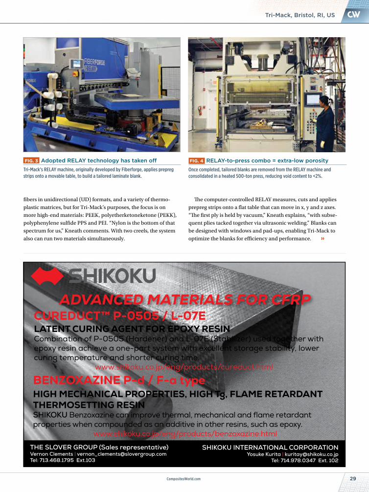
29CompositesWorld.com
NEWSTri-Mack, Bristol, RI, US
FIG. 4 RELAY-to-press combo = extra-low porosityOnce completed, tailored blanks are removed from the RELAY machine and consolidated in a heated 500-ton press, reducing void content to <2%.
FIG. 3 Adopted RELAY technology has taken off Tri-Mack’s RELAY machine, originally developed by Fiberforge, applies prepreg strips onto a movable table, to build a tailored laminate blank.
2006.10.30A logo mark “Shikoku Chemicals Corporation”
ADVANCED MATERIALS FOR CFRP
LATENT CURING AGENT FOR EPOXY RESINCombination of P-0505 (Hardener) and L-07E (Stabilizer) used together with epoxy resin achieve a one-part system with excellent storage stability, lower curing temperature and shorter curing time.
www.shikoku.co.jp/eng/products/cureduct.html
HIGH MECHANICAL PROPERTIES, HIGH Tg, FLAME RETARDANT THERMOSETTING RESINSHIKOKU Benzoxazine can improve thermal, mechanical and flame retardant properties when compounded as an additive in other resins, such as epoxy.
www.shikoku.co.jp/eng/products/benzoxazine.html
CUREDUCT™ P-0505 / L-07E
BENZOXAZINE P-d / F-a type
THE SLOVER GROUP (Sales representative)Vernon Clements | [email protected]: 713.468.1795 Ext.103
SHIKOKU INTERNATIONAL CORPORATIONYosuke Kurita | [email protected]
Tel: 714.978.0347 Ext. 102
fibers in unidirectional (UD) formats, and a variety of thermo-
plastic matrices, but for Tri-Mack’s purposes, the focus is on
more high-end materials: PEEK, polyetherketoneketone (PEKK),
polyphenylene sulfide PPS and PEI. “Nylon is the bottom of that
spectrum for us,” Kneath comments. With two creels, the system
also can run two materials simultaneously.
The computer-controlled RELAY measures, cuts and applies
prepreg strips onto a flat table that can move in x, y and z axes.
“The first ply is held by vacuum,” Kneath explains, “with subse-
quent plies tacked together via ultrasonic welding.” Blanks can
be designed with windows and pad-ups, enabling Tri-Mack to
optimize the blanks for efficiency and performance.
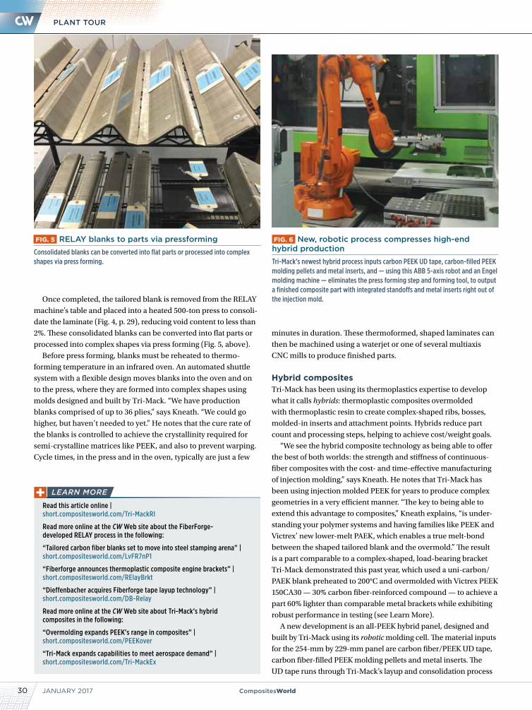
JANUARY 201730 CompositesWorld
PLANT TOUR
minutes in duration. These thermoformed, shaped laminates can
then be machined using a waterjet or one of several multiaxis
CNC mills to produce finished parts.
Hybrid compositesTri-Mack has been using its thermoplastics expertise to develop
what it calls hybrids: thermoplastic composites overmolded
with thermoplastic resin to create complex-shaped ribs, bosses,
molded-in inserts and attachment points. Hybrids reduce part
count and processing steps, helping to achieve cost/weight goals.
“We see the hybrid composite technology as being able to offer
the best of both worlds: the strength and stiffness of continuous-
fiber composites with the cost- and time-effective manufacturing
of injection molding,” says Kneath. He notes that Tri-Mack has
been using injection molded PEEK for years to produce complex
geometries in a very efficient manner. “The key to being able to
extend this advantage to composites,” Kneath explains, “is under-
standing your polymer systems and having families like PEEK and
Victrex’ new lower-melt PAEK, which enables a true melt-bond
between the shaped tailored blank and the overmold.” The result
is a part comparable to a complex-shaped, load-bearing bracket
Tri-Mack demonstrated this past year, which used a uni-carbon/
PAEK blank preheated to 200°C and overmolded with Victrex PEEK
150CA30 — 30% carbon fiber-reinforced compound — to achieve a
part 60% lighter than comparable metal brackets while exhibiting
robust performance in testing (see Learn More).
A new development is an all-PEEK hybrid panel, designed and
built by Tri-Mack using its robotic molding cell. The material inputs
for the 254-mm by 229-mm panel are carbon fiber/PEEK UD tape,
carbon fiber-filled PEEK molding pellets and metal inserts. The
UD tape runs through Tri-Mack’s layup and consolidation process
Once completed, the tailored blank is removed from the RELAY
machine’s table and placed into a heated 500-ton press to consoli-
date the laminate (Fig. 4, p. 29), reducing void content to less than
2%. These consolidated blanks can be converted into flat parts or
processed into complex shapes via press forming (Fig. 5, above).
Before press forming, blanks must be reheated to thermo-
forming temperature in an infrared oven. An automated shuttle
system with a flexible design moves blanks into the oven and on
to the press, where they are formed into complex shapes using
molds designed and built by Tri-Mack. “We have production
blanks comprised of up to 36 plies,” says Kneath. “We could go
higher, but haven’t needed to yet.” He notes that the cure rate of
the blanks is controlled to achieve the crystallinity required for
semi-crystalline matrices like PEEK, and also to prevent warping.
Cycle times, in the press and in the oven, typically are just a few
FIG. 6 New, robotic process compresses high-end hybrid productionTri-Mack’s newest hybrid process inputs carbon PEEK UD tape, carbon-filled PEEK molding pellets and metal inserts, and — using this ABB 5-axis robot and an Engel molding machine — eliminates the press forming step and forming tool, to output a finished composite part with integrated standoffs and metal inserts right out of the injection mold.
FIG. 5 RELAY blanks to parts via pressformingConsolidated blanks can be converted into flat parts or processed into complex shapes via press forming.
Read this article online | short.compositesworld.com/Tri-MackRI
Read more online at the CW Web site about the FiberForge- developed RELAY process in the following:
“Tailored carbon fiber blanks set to move into steel stamping arena” | short.compositesworld.com/LvFR7nP1
“Fiberforge announces thermoplastic composite engine brackets” | short.compositesworld.com/RElayBrkt
“Dieffenbacher acquires Fiberforge tape layup technology” | short.compositesworld.com/DB-Relay
Read more online at the CW Web site about Tri-Mack’s hybrid composites in the following:
“Overmolding expands PEEK’s range in composites” | short.compositesworld.com/PEEKover
“Tri-Mack expands capabilities to meet aerospace demand” | short.compositesworld.com/Tri-MackEx
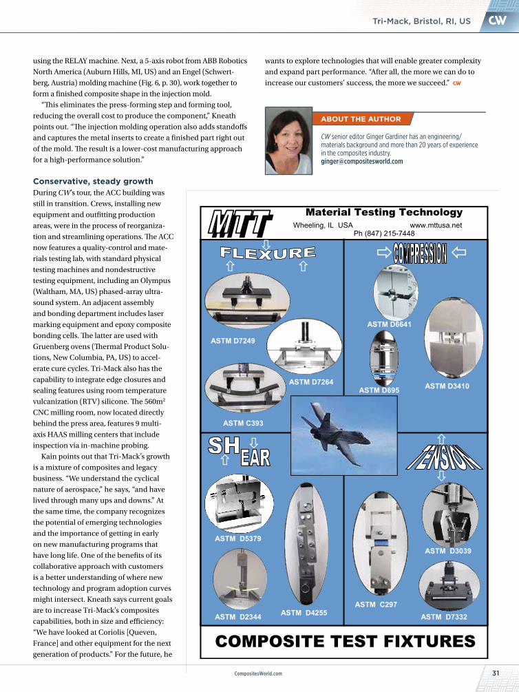
31CompositesWorld.com
NEWSTri-Mack, Bristol, RI, US
wants to explore technologies that will enable greater complexity
and expand part performance. “After all, the more we can do to
increase our customers’ success, the more we succeed.”
using the RELAY machine. Next, a 5-axis robot from ABB Robotics
North America (Auburn Hills, MI, US) and an Engel (Schwert-
berg, Austria) molding machine (Fig. 6, p. 30), work together to
form a finished composite shape in the injection mold.
“This eliminates the press-forming step and forming tool,
reducing the overall cost to produce the component,” Kneath
points out. “The injection molding operation also adds standoffs
and captures the metal inserts to create a finished part right out
of the mold. The result is a lower-cost manufacturing approach
for a high-performance solution.”
Conservative, steady growthDuring CW’s tour, the ACC building was
still in transition. Crews, installing new
equipment and outfitting production
areas, were in the process of reorganiza-
tion and streamlining operations. The ACC
now features a quality-control and mate-
rials testing lab, with standard physical
testing machines and nondestructive
testing equipment, including an Olympus
(Waltham, MA, US) phased-array ultra-
sound system. An adjacent assembly
and bonding department includes laser
marking equipment and epoxy composite
bonding cells. The latter are used with
Gruenberg ovens (Thermal Product Solu-
tions, New Columbia, PA, US) to accel-
erate cure cycles. Tri-Mack also has the
capability to integrate edge closures and
sealing features using room temperature
vulcanization (RTV) silicone. The 560m2
CNC milling room, now located directly
behind the press area, features 9 multi-
axis HAAS milling centers that include
inspection via in-machine probing.
Kain points out that Tri-Mack’s growth
is a mixture of composites and legacy
business. “We understand the cyclical
nature of aerospace,” he says, “and have
lived through many ups and downs.” At
the same time, the company recognizes
the potential of emerging technologies
and the importance of getting in early
on new manufacturing programs that
have long life. One of the benefits of its
collaborative approach with customers
is a better understanding of where new
technology and program adoption curves
might intersect. Kneath says current goals
are to increase Tri-Mack’s composites
capabilities, both in size and efficiency:
“We have looked at Coriolis [Queven,
France] and other equipment for the next
generation of products.” For the future, he
CW senior editor Ginger Gardiner has an engineering/ materials background and more than 20 years of experience in the composites industry. [email protected]
COMPOSITE TEST FIXTURES
Wheeling, IL USA www.mttusa.net
Material Testing Technology
Ph (847) 215-7448
ASTM D3410
ASTM D7249
ASTM D2344 ASTM D4255
ASTM D5379
ASTM C297 ASTM D7332
ASTM D6641
ASTM D695 ASTM D7264
ASTM C393
ASTM D3039
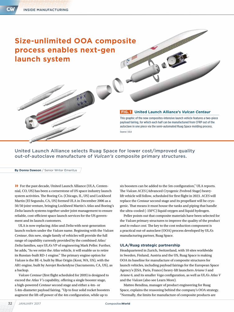
JANUARY 201732 CompositesWorld
INSIDE MANUFACTURING
United Launch Alliance selects Ruag Space for lower cost/improved quality out-of-autoclave manufacture of Vulcan’s composite primary structures.
» For the past decade, United Launch Alliance (ULA, Centen-
nial, CO, US) has been a cornerstone of US space industry launch
system activities. The Boeing Co. (Chicago, IL, US) and Lockheed
Martin (El Segundo, CA, US) formed ULA in December 2006 as a
50/50 joint venture, bringing Lockheed Martin’s Atlas and Boeing’s
Delta launch systems together under joint management to ensure
reliable, cost-efficient space launch services for the US govern-
ment and its launch customers.
ULA is now replacing Atlas and Delta with next-generation
launch rockets under the Vulcan name. Beginning with the Vulcan
Centaur, this new, single family of vehicles will provide the full
range of capability currently provided by the combined Atlas/
Delta families, says ULA’s VP of engineering Mark Peller. Further,
he adds, “As we retire the Atlas vehicle, it will enable us to retire
its Russian-built RD-1 engine.” The primary engine option for
Vulcan is the BE-4, built by Blue Origin (Kent, WA, US), with the
AR1 engine, built by Aerojet Rocketdyne (Sacramento, CA, US), as
a backup.
Vulcan Centaur (first flight scheduled for 2019) is designed to
exceed the Atlas V’s capability, offering a single booster stage,
a high-powered Centaur second stage and either a 4m- or
5.4m-diameter payload fairing. “Up to four solid rocket boosters
augment the lift-off power of the 4m configuration, while up to
six boosters can be added to the 5m configuration,” ULA reports.
The Vulcan ACES (Advanced Cryogenic Evolved Stage) heavy-
lift vehicle will follow, scheduled for first flight in 2023. ACES will
replace the Centaur second stage and its propellant will be cryo-
genic. That means it must house the tanks and piping that handle
the ultra-cooled (-150°C) liquid oxygen and liquid hydrogen.
Peller points out that composite materials have been selected for
the Vulcan primary structures to improve the quality of the product
and to reduce cost. The key to the cost reduction component is
a practical out-of-autoclave (OOA) process developed by ULA’s
manufacturing partner, Ruag Space.
ULA/Ruag strategic partnership Headquartered in Zurich, Switzerland, with 10 sites worldwide
in Sweden, Finland, Austria and the US, Ruag Space is making
OOA its baseline for manufacture of composite structures for
launch vehicles, including payload fairings for the European Space
Agency’s (ESA, Paris, France) heavy-lift launchers Ariane 5 and
Ariane 6, and its smaller Vega configuration, as well as ULA’s Atlas V
and the Vulcan (also see Learn More).
Matteo Rendina, manager of product engineering for Ruag
Space, explains the reasoning behind the company’s OOA strategy.
“Normally, the limits for manufacture of composite products are
Size-unlimited OOA composite process enables next-gen launch system
FIG. 1 United Launch Alliance’s Vulcan CentaurThis graphic of the new composites-intensive launch vehicle features a two-piece payload fairing, for which each half can be manufactured from CFRP out of the autoclave in one piece via the semi-automated Ruag Space molding process.
Source | ULA
By Donna Dawson / Senior Writer Emeritus
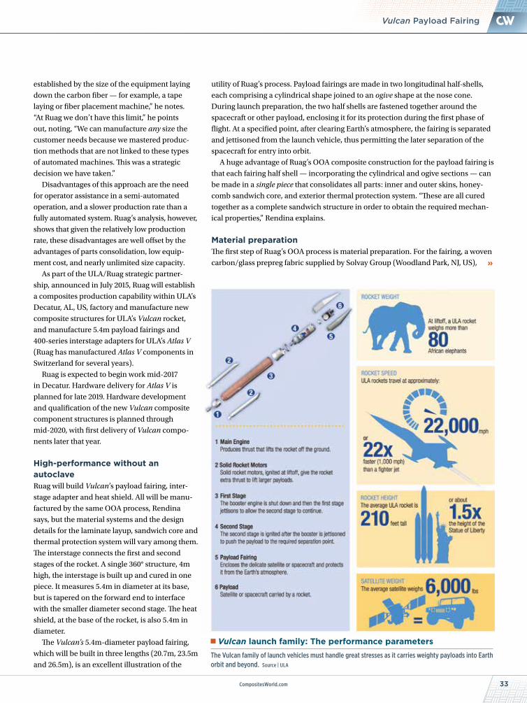
CompositesWorld.com 33
NEWS
established by the size of the equipment laying
down the carbon fiber — for example, a tape
laying or fiber placement machine,” he notes.
“At Ruag we don’t have this limit,” he points
out, noting, “We can manufacture any size the
customer needs because we mastered produc-
tion methods that are not linked to these types
of automated machines. This was a strategic
decision we have taken.”
Disadvantages of this approach are the need
for operator assistance in a semi-automated
operation, and a slower production rate than a
fully automated system. Ruag’s analysis, however,
shows that given the relatively low production
rate, these disadvantages are well offset by the
advantages of parts consolidation, low equip-
ment cost, and nearly unlimited size capacity.
As part of the ULA/Ruag strategic partner-
ship, announced in July 2015, Ruag will establish
a composites production capability within ULA’s
Decatur, AL, US, factory and manufacture new
composite structures for ULA’s Vulcan rocket,
and manufacture 5.4m payload fairings and
400-series interstage adapters for ULA’s Atlas V
(Ruag has manufactured Atlas V components in
Switzerland for several years).
Ruag is expected to begin work mid-2017
in Decatur. Hardware delivery for Atlas V is
planned for late 2019. Hardware development
and qualification of the new Vulcan composite
component structures is planned through
mid-2020, with first delivery of Vulcan compo-
nents later that year.
High-performance without an autoclave Ruag will build Vulcan’s payload fairing, inter-
stage adapter and heat shield. All will be manu-
factured by the same OOA process, Rendina
says, but the material systems and the design
details for the laminate layup, sandwich core and
thermal protection system will vary among them.
The interstage connects the first and second
stages of the rocket. A single 360° structure, 4m
high, the interstage is built up and cured in one
piece. It measures 5.4m in diameter at its base,
but is tapered on the forward end to interface
with the smaller diameter second stage. The heat
shield, at the base of the rocket, is also 5.4m in
diameter.
The Vulcan’s 5.4m-diameter payload fairing,
which will be built in three lengths (20.7m, 23.5m
and 26.5m), is an excellent illustration of the
utility of Ruag’s process. Payload fairings are made in two longitudinal half-shells,
each comprising a cylindrical shape joined to an ogive shape at the nose cone.
During launch preparation, the two half shells are fastened together around the
spacecraft or other payload, enclosing it for its protection during the first phase of
flight. At a specified point, after clearing Earth’s atmosphere, the fairing is separated
and jettisoned from the launch vehicle, thus permitting the later separation of the
spacecraft for entry into orbit.
A huge advantage of Ruag’s OOA composite construction for the payload fairing is
that each fairing half shell — incorporating the cylindrical and ogive sections — can
be made in a single piece that consolidates all parts: inner and outer skins, honey-
comb sandwich core, and exterior thermal protection system. “These are all cured
together as a complete sandwich structure in order to obtain the required mechan-
ical properties,” Rendina explains.
Material preparationThe first step of Ruag’s OOA process is material preparation. For the fairing, a woven
carbon/glass prepreg fabric supplied by Solvay Group (Woodland Park, NJ, US),
Vulcan launch family: The performance parametersThe Vulcan family of launch vehicles must handle great stresses as it carries weighty payloads into Earth orbit and beyond. Source | ULA
Vulcan Payload Fairing
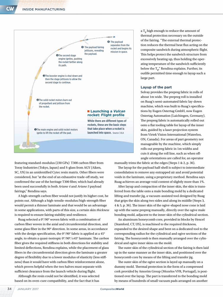
34 CompositesWorldJANUARY 2017
INSIDE MANUFACTURING
featuring standard-modulus (230 GPa) T300 carbon fiber from
Toray Industries (Tokyo, Japan) and S-glass from AGY (Aiken,
SC, US) in an unidentified Cytec resin matrix. Other fibers were
considered, but “at the end of an exhaustive trade-off study, we
confirmed the use of the heritage T300 fiber, which had already
been used successfully in both Ariane 4 and Ariane 5 payload
fairings,” Rendina says.
A high-strength carbon fiber would not justify its higher cost, he
points out. Although a high-tensile-modulus/high-strength fiber
would permit a thinner laminate and that would be an advantage
in some applications, with parts of this size, a certain skin thickness
is required to ensure fairing stability and resilience.
Ruag selected a 0°/90° woven fabric with a combination of
carbon fiber woven in the axial and circumferential direction, and
some glass fiber in the 90° direction. In some areas, in accordance
with the design specification, the 0°/90° fabric is applied at a 45°
angle, to obtain a quasi-isotropic 0°/90°/±45° laminate. The carbon
fiber gives the required stiffness in both directions for stability and
limited deflections, Rendina explains, while the placement of glass
fibers in the circumferential direction gives the laminate a greater
degree of flexibility due to a lower modulus of elasticity (less stiff-
ness) than it would have with carbon fiber reinforcement alone,
which proves helpful when the two halves must separate with
sufficient clearance from the launch vehicle during flight.
Although the resin could not be identified, it was selected
based on its oven-cure compatibility, and the fact that it has
a Tg high enough to reduce the amount of
thermal protection necessary on the outside
of the fairing. “The external thermal protec-
tion reduces the thermal heat flux acting on the
composite sandwich during atmospheric flight.
This helps protect the sandwich structure from
excessively heating up, thus holding the oper-
ating temperature of the sandwich sufficiently
below the Tg,” Rendina explains. Further, its
outlife permitted time enough to layup such a
large part.
Layup of the partSolvay provides the prepreg fabric in rolls of
about 1m wide. The prepreg roll is installed
on Ruag’s semi-automated fabric lay-down
machine, which was built to Ruag’s specifica-
tions by Eugen Ostertag GmbH, now Eugen
Ostertag Automation (Laichingen, Germany).
The prepreg fabric is automatically rolled out
onto a flat tooling table for layup of the inner
skin, guided by a laser projection system
from Virtek Vision International (Waterloo,
ON, Canada). For areas of part geometry not
manageable by the machine, which simply
rolls out prepreg fabric in 1m widths and
cuts it along the roll line, such as when off-
angle orientations are called for, an operator
manually trims the fabric at the edges (Steps 1 & 2, p. 36).
The layup for the payload half-shell is subject to intermediate
consolidation to remove any entrapped air and avoid potential
voids in the laminate, using a proprietary method. Rendina says
Ruag achieves an average void content of slightly more than 1%.
After layup and compaction of the inner skin, the skin is trans-
ferred from the table onto a male bonding mold by a dedicated
lifting and transfer jig, a vacuum-assisted tool designed by Ruag
that grips the skin along two sides and along its middle (Steps 3,
4 & 5, p. 36). The inner skin of the ogive-shaped nose cone is laid
up with the same prepreg manually, directly over the ogive male
bonding mold, adjacent to the inner skin of the cylindrical section.
An aluminum honeycomb core, provided in blocks by Hexcel
(Stamford, CT, US), is machined to the required thickness,
expanded to the desired shape and bent on a dedicated tool to the
corresponding radius for the cylindrical and ogive sections of the
fairing. The honeycomb is then manually arranged over the cylin-
drical and ogive inner skins on the mold.
The outer skin of the cylindrical section of the fairing is then laid
up in the same manner as the inner skin, and positioned over the
honeycomb core by means of the lifting and transfer jig.
The outer skin of the ogive section is layed up manually on a
dummy mold. Thermal protection in the form of a compressed
cork provided by Amorim Group (Mozelos VFR, Portugal), is posi-
tioned over the layup. The part is transferred to the bonding mold
by means of hundreds of small vacuum pads arranged on another
Launching a Vulcan rocket: Flight profileWhile there are different types of rockets, these are the basic steps that take place when a rocket is launched into space. Source | ULA
➏ The payload separates from the rocket and begins its mission in space.
❺ The payload fairing jettisons, revealing the payload.
❹ The second stage engine ignites, pushing the rocket farther along its path.
❸ The booster engine is shut down and then the stage jettisons to allow the second stage to continue.
❷ The solid rocket motors burn out of propellant and jettison from the rocket.
❶ The main engine and solid rocket motors ignite to lift the rocket off the pad.
CompositesWorld.com 35
NEWSVulcan Payload Fairing
dedicated jig (Step 6, p. 36). Lastly, a layer of the cork is arranged
over the outer skin of the cylindrical section. The cork, bonded on
the outside skin of the fairing’s composite sandwich protects the
sandwich from the aerodynamic frictional heat generated on the
fairing’s exterior. The complete part sandwich layup is now ready
for vacuum bagging and cure.
Curing processCuring is performed once for each fairing half shell. “The end
product of the cure is a composite shell, thermally protected, on
which all the subsystems required by the payload fairing will be
assembled,” Rendina points out. Those are installed mainly on the
inside of the fairing (instrumentation, venting system, acoustic
protection system), but some are placed on the main structural
path (separation systems) and some on the external side of the
fairing (interfaces to the ground).
Each fairing half shell is cured in a large oven (Step 7, p. 37),
supplied by Luterbach AG (Hildisrieden, Switzerland) according
to a specific time and temperature profile established “after inves-
tigating the effect of different parameters on the resulting material
performance,” Rendina says. These include the viscosity and Tg
(high) of the resin; the application of a vacuum level that best facil-
itates air evacuation and achieves thorough consolidation; and
realization of a homogeneous cure that curtails hot and cold areas,
to limit part distortions.
To ensure the latter, Ruag has conducted extensive computa-
tional fluid dynamics (CFD) analyses on the air circulation inside
the oven to ensure even temperature distribution over the entire
part. After cure, the fairing shell is lifted from the mold by a lifting
jig, also equipped with vacuum pads, and transferred to the next
station for nondestructive testing.
Ruag has to guarantee the quality of each article delivered to its
customers, Rendina says. But to accomplish this cost-effectively,
testing must be limited. The company validates its guarantee in
several ways. First, it confirms quality and consistency during
production of each part. This is especially important during cure.
“We diligently pursued, and achieved, a curing process with suffi-
ciently large boundaries from the nominal curing path. We are
confident in now having sufficient control parameters to justify the
quality of the structure.”
Acceptance tests are, therefore, limited to nondestructive
inspection (NDI) of the complete shell after cure, plus visual
inspections after each postcure operation. NDI is accomplished
via a 200-kHz, air-coupled ultrasonic through-transmission with
scan resolution adjustable between 0.1 mm and 50 mm. Scan time
is about 20 min/m2. Ostertag supplied the NDI system, which is
carried on a robot from Robot Technology GmbH (Grossostheim,
Germany). “Further, sacrificial test panels are manufactured
together with each composite shell, and samples can be cut out
of these panels in-process if material characteristics need to be
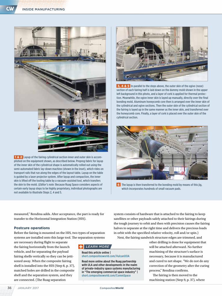
JANUARY 201736 CompositesWorld
INSIDE MANUFACTURING
measured,” Rendina adds. After acceptance, the part is ready for
transfer to the Horizontal Integration Station (HIS).
Postcure operationsBefore the fairing is mounted on the HIS, two types of separation
systems are installed onto this large tool. The separation systems
are necessary during flight to separate
the fairing horizontally from the launch
vehicle, and for separating the payload
fairing shells vertically so they can be jetti-
soned away. When the composite fairing
shell is installed into the HIS (Step 8, p. 37),
matched holes are drilled in the composite
shell and the separation system, and they
are connected. (The Ruag separation
system consists of hardware that is attached to the fairing to keep
satellites or other payloads safely attached to their fairings during
the tough journey to orbit and then with precision causes the fairing
halves to separate at the right time and delivers the precious loads
in orbit with the specified relative velocity, roll and/or spin.) Next, the fairing sandwich structure edges are trimmed, and
other drilling is done for equipment that
will be attached afterward. No further
machining of the structure’s surface is
necessary, because it is manufactured
and cured to net shape. “We do not do any
correction of the geometry after the curing
process,” Rendina confirms.
The fairing is then moved to the
machining station (Step 9, p. 37), where
6 The layup is then transferred to the bonding mold by means of this jig, which incorporates hundreds of small vacuum pads.
3, 4 & 5 In parallel to the steps above, the outer skin of the ogive (nose) section of each fairing half is laid down on the dummy mold shown in the upper left background in this photo, and a layer of cork is applied for thermal protec-tion. Meanwhile, the ogive inner skin is layed up manually, directly over the final bonding mold. Aluminum honeycomb core then is arranged over the inner skin of the cylindrical and ogive sections. Then the outer skin of the cylindrical section of the fairing is layed up in the same manner as the inner skin, and transferred over the honeycomb core. Finally, a layer of cork is placed over the outer skin of the cylindrical section.
1 & 2 Layup of the fairing cylindrical section inner and outer skin is accom-plished on the equipment shown, as described below. Prepreg fabric for layup of the inner skin of the cylindrical shape is automatically rolled out using the semi-automated fabric lay-down machine (shown in the inset), which rides on transport rails that run along the edges of the layout table. Layup on the table is guided by a laser projector system. After layup and compaction, the inner skin is lifted off the tooling table by a vacuum-assisted tool, which transfers the skin to the mold. (Editor’s note: Because Ruag Space considers aspects of certain early layup steps to be highly proprietary, individual photographs are not available to illustrate Steps 2, 4 and 5.
Read this article online | short.compositesworld.com/VulcanOOA
Read more online about the Ruag partnership with ULA and other developments in the realm of private-industry space systems manufacturing in “The emerging commercial space industry” | short.compositesworld.com/CommSpace
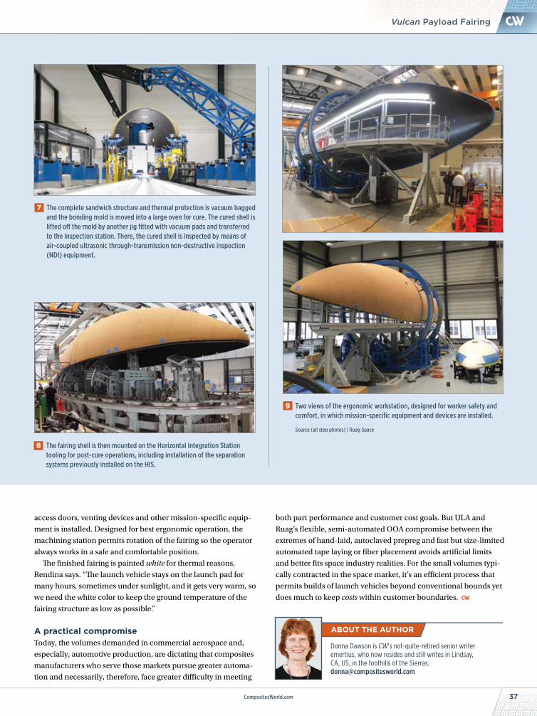
37CompositesWorld.com
NEWSVulcan Payload Fairing
7 The complete sandwich structure and thermal protection is vacuum bagged and the bonding mold is moved into a large oven for cure. The cured shell is lifted off the mold by another jig fitted with vacuum pads and transferred to the inspection station. There, the cured shell is inspected by means of air-coupled ultrasonic through-transmission non-destructive inspection (NDI) equipment.
Donna Dawson is CW’s not-quite-retired senior writer emertius, who now resides and still writes in Lindsay, CA, US, in the foothills of the Sierras. [email protected]
access doors, venting devices and other mission-specific equip-
ment is installed. Designed for best ergonomic operation, the
machining station permits rotation of the fairing so the operator
always works in a safe and comfortable position.
The finished fairing is painted white for thermal reasons,
Rendina says. “The launch vehicle stays on the launch pad for
many hours, sometimes under sunlight, and it gets very warm, so
we need the white color to keep the ground temperature of the
fairing structure as low as possible.”
A practical compromiseToday, the volumes demanded in commercial aerospace and,
especially, automotive production, are dictating that composites
manufacturers who serve those markets pursue greater automa-
tion and necessarily, therefore, face greater difficulty in meeting
both part performance and customer cost goals. But ULA and
Ruag’s flexible, semi-automated OOA compromise between the
extremes of hand-laid, autoclaved prepreg and fast but size-limited
automated tape laying or fiber placement avoids artificial limits
and better fits space industry realities. For the small volumes typi-
cally contracted in the space market, it’s an efficient process that
permits builds of launch vehicles beyond conventional bounds yet
does much to keep costs within customer boundaries.
8 The fairing shell is then mounted on the Horizontal Integration Station tooling for post-cure operations, including installation of the separation systems previously installed on the HIS.
9 Two views of the ergonomic workstation, designed for worker safety and comfort, in which mission-specific equipment and devices are installed.
Source (all step photos) | Ruag Space
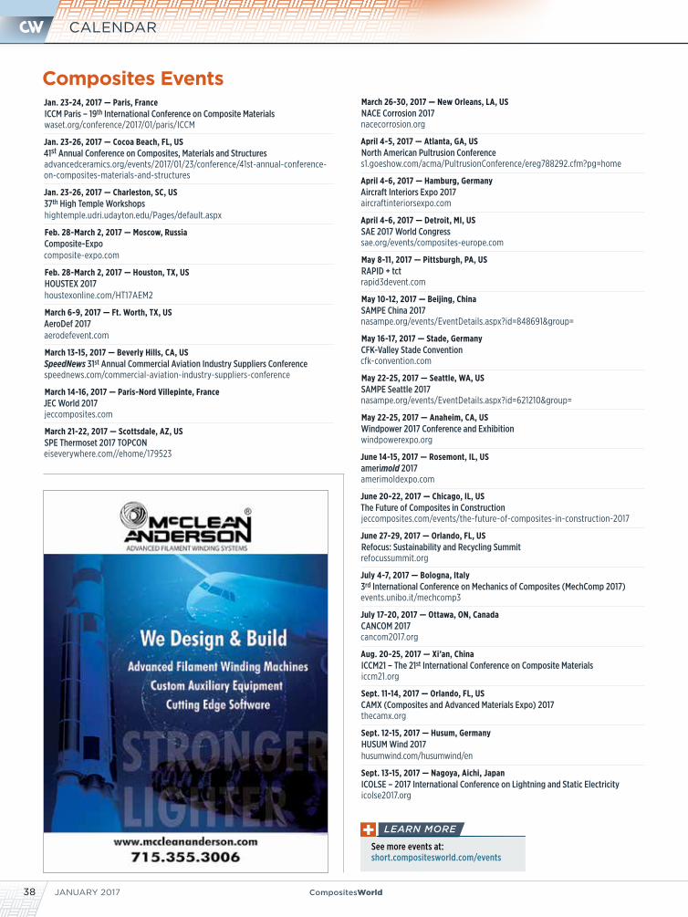
JANUARY 201738 CompositesWorld
CALENDAR
Composites Events
See more events at: short.compositesworld.com/events
Jan. 23-24, 2017 — Paris, FranceICCM Paris – 19th International Conference on Composite Materialswaset.org/conference/2017/01/paris/ICCM
Jan. 23-26, 2017 — Cocoa Beach, FL, US41st Annual Conference on Composites, Materials and Structuresadvancedceramics.org/events/2017/01/23/conference/41st-annual-conference-on-composites-materials-and-structures
Jan. 23-26, 2017 — Charleston, SC, US 37th High Temple Workshopshightemple.udri.udayton.edu/Pages/default.aspx
Feb. 28-March 2, 2017 — Moscow, RussiaComposite-Expocomposite-expo.com
Feb. 28-March 2, 2017 — Houston, TX, US HOUSTEX 2017houstexonline.com/HT17AEM2
March 6-9, 2017 — Ft. Worth, TX, USAeroDef 2017aerodefevent.com
March 13-15, 2017 — Beverly Hills, CA, US SpeedNews 31st Annual Commercial Aviation Industry Suppliers Conferencespeednews.com/commercial-aviation-industry-suppliers-conference
March 14-16, 2017 — Paris-Nord Villepinte, FranceJEC World 2017jeccomposites.com
March 21-22, 2017 — Scottsdale, AZ, USSPE Thermoset 2017 TOPCONeiseverywhere.com//ehome/179523
March 26-30, 2017 — New Orleans, LA, US NACE Corrosion 2017nacecorrosion.org
April 4-5, 2017 — Atlanta, GA, USNorth American Pultrusion Conferences1.goeshow.com/acma/PultrusionConference/ereg788292.cfm?pg=home
April 4-6, 2017 — Hamburg, Germany Aircraft Interiors Expo 2017aircraftinteriorsexpo.com
April 4-6, 2017 — Detroit, MI, US SAE 2017 World Congresssae.org/events/composites-europe.com
May 8-11, 2017 — Pittsburgh, PA, USRAPID + tctrapid3devent.com
May 10-12, 2017 — Beijing, ChinaSAMPE China 2017nasampe.org/events/EventDetails.aspx?id=848691&group=
May 16-17, 2017 — Stade, GermanyCFK-Valley Stade Conventioncfk-convention.com
May 22-25, 2017 — Seattle, WA, USSAMPE Seattle 2017nasampe.org/events/EventDetails.aspx?id=621210&group=
May 22-25, 2017 — Anaheim, CA, US Windpower 2017 Conference and Exhibitionwindpowerexpo.org
June 14-15, 2017 — Rosemont, IL, USamerimold 2017 amerimoldexpo.com
June 20-22, 2017 — Chicago, IL, USThe Future of Composites in Constructionjeccomposites.com/events/the-future-of-composites-in-construction-2017
June 27-29, 2017 — Orlando, FL, USRefocus: Sustainability and Recycling Summitrefocussummit.org
July 4-7, 2017 — Bologna, Italy3rd International Conference on Mechanics of Composites (MechComp 2017)events.unibo.it/mechcomp3
July 17-20, 2017 — Ottawa, ON, CanadaCANCOM 2017cancom2017.org
Aug. 20-25, 2017 — Xi’an, China ICCM21 – The 21st International Conference on Composite Materialsiccm21.org
Sept. 11-14, 2017 — Orlando, FL, USCAMX (Composites and Advanced Materials Expo) 2017thecamx.org
Sept. 12-15, 2017 — Husum, GermanyHUSUM Wind 2017husumwind.com/husumwind/en
Sept. 13-15, 2017 — Nagoya, Aichi, JapanICOLSE – 2017 International Conference on Lightning and Static Electricityicolse2017.org
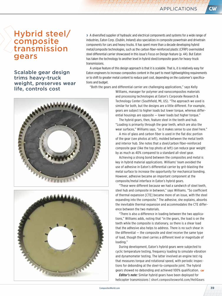
39CompositesWorld.com
APPLICATIONS
Scalable gear design trims heavy-truck weight, preserves wear life, controls cost
Hybrid steel/composite transmission gears
› A diversified supplier of hydraulic and electrical components and systems for a wide range of industries, Eaton Corp. (Dublin, Ireland) also specializes in composite powertrain and drivetrain components for cars and heavy trucks. It has spent more than a decade developing hybrid metal/composite technologies, such as the carbon fiber-reinforced plastic (CFRP) overmolded steel differential carrier showcased in this issue’s Focus on Design feature (p. 44). But Eaton has taken the technology to another level in hybrid steel/composite gears for heavy-truck transmissions.
A unique feature of this design approach is that it is scalable. That is, it is relatively easy for Eaton engineers to increase composites content in the part to meet lightweighting requirements or to shift to greater metal content to reduce part cost, depending on the customer’s specifica-tions and budget.
“Both the gears and differential carrier are challenging applications,” says Kelly Williams, manager for polymer and nanocomposites materials and processing technologies at Eaton’s Corporate Research & Technology Center (Southfield, MI, US). “The approach we used is similar for both, but the designs are a little different. For example, gears are subject to higher loads but lower torque, whereas differ-ential housings are opposite — lower loads but higher torque.”
The hybrid gears, then, feature steel in the teeth and hub. “Loading is primarily through the gear teeth, which are also the wear surfaces,” Williams says, “so it makes sense to use steel here.”
A mix of glass and carbon fiber is used in the flat disc portion of the gear (see photos at left), molded between the metal teeth and interior hub. She notes that a steel/carbon fiber-reinforced composite gear (like the top photo at left) can reduce gear weight by as much as 40% compared to a standard all-steel gear.
Achieving a strong bond between the composites and metal is key in hybrid material applications. Williams’ team avoided the use of adhesive in Eaton’s differential carrier by grit-blasting the metal surface to increase the opportunity for mechanical bonding. However, adhesive became an important component at the composite/metal interface in Eaton’s hybrid gears.
“These were different because we had a sandwich of steel teeth, steel hub and composite in between,” says Williams. “So coefficient of thermal expansion [CTE] became more of an issue, with the steel expanding into the composite.” The adhesive, she explains, absorbs the inevitable thermal expansion and accommodates the CTE differ-ence between the two materials.
“There is also a difference in loading between the two applica-tions,” Williams adds, noting that “in the gears, the load is on the teeth while the composite is stationary, so there is a shear load that the adhesive also helps to address. There is no such shear in the differential — the composite and steel receive the same type of load, though the steel carries a different level or magnitude of loading.”
During development, Eaton’s hybrid gears were subjected to cyclic temperature testing, frequency loading to simulate vibration and dynamometer testing. The latter involved an engine test rig that measures torque and rotational speed, with periodic inspec-tions for debonding at the steel-to-composite joint. The hybrid gears showed no debonding and achieved 100% qualification.
Editor’s note: Similar hybrid gears have been deployed for helicopter transmissions | short.compositesworld.com/HeliGears
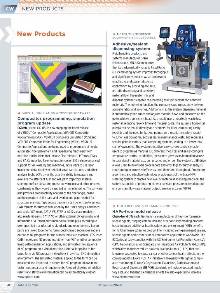
JANUARY 201740 CompositesWorld
New Products
NEW PRODUCTS
» VIRTUAL SIMULATION & TESTING SOFTWARE
Composites programming, simulation program updateCGTech (Irvine, CA, US) is now shipping the latest release of VERICUT Composite Applications: VERICUT Composite Programming (VCP), VERICUT Composite Simulation (VCS) and VERICUT Composite Paths for Engineering (VCPe). VERICUT Composite Applications are being used to program and simulate automated fiber placement and tape-laying machinery from machine tool builders that include Electroimpact, MTorres, Fives and BA Composites. New features in version 8.0 include enhanced support for AFP/ATL hybrid machines, more ways to use laser inspection data, display of detailed scrap calculations, and other analysis tools. VCPe gives the user the ability to measure and evaluate the effects of AFP and ATL path trajectory, material steering, surface curvature, course convergence and other process constraints as they would be applied in manufacturing. The software also provides produceability analysis of the fiber angle, based on the curvature of the part, and overlap and gaps needed for structural analysis. Tape course geometry can be written to various CAD formats for further evaluation by the user’s analysis methods and tools. VCP reads CATIA V5, STEP or ACIS surface models. It also reads Fibersim, CATIA V5 or other external ply geometry and information. VCP then adds material to fill the plies according to user-specified manufacturing standards and requirements. Layup paths are linked together to form specific layup sequences and are output as NC programs for the automated layup machine. VCS reads CAD models and NC programs, either from VCP or other composite layup path-generation applications, and simulates the sequence of NC programs on a virtual machine. Material is applied to the layup form via NC program instructions in a virtual CNC simulation environment. The simulated material applied to the form can be measured and inspected to ensure the NC program follows manu-facturing standards and requirements. A report showing simulation results and statistical information can be automatically created. www.cgtech.com
» METER/MIX/DISPENSE EQUIPMENT & ACCESSORIES
Adhesive/sealant dispensing systemFluid handling products and systems manufacturer Graco (MInneapolis, MN, US) announced that its trademarked Hydraulic Fixed Ratio (HFR) metering system improves throughput and significantly reduces waste and rework in adhesive and sealant dispense applications by providing accurate, on-ratio dispensing and consistent material flow. The meter, mix and dispense system is capable of processing multiple sealant and adhesive materials. The metering function, the company says, consistently delivers accurate ratios and volumes. Additionally, as the system dispenses material, it automatically fine-tunes and adjusts material flows and pressures on the go to achieve a consistent bead. As a result, users reportedly waste less material, reducing rework time and material costs. The system’s horizontal pumps can be rebuilt directly at customers’ facilities, eliminating costly rebuilds and the need for backup pumps. As a result, the system is said to suffer less downtime, accrues less in maintenance costs, and requires a smaller parts inventory than competing systems, leading to a lower total cost of ownership. The system’s intuitive, easy-to-use controls enable users to program as many as 100 different shot sizes and easily configure temperature control. In addition, the system gives users immediate access to data about material use, pump cycles and errors. The system’s USB drive allows users to download process data and error logs for further analysis, contributing to increased efficiency and, therefore, throughput. Proprietary algorithms and adaptive technology enable users of the Graco HFR Metering system to reach a new level of material dispensing precision; the system is capable of producing either a constant pressure material output or a constant flow rate material output. www.graco.com/HFRG
» MOLD RELEASE & CLEANING PRODUCTS
HAPs-free mold releaseChem-Trend (Maisach, Germany), a manufacturer of high-performance release agents, purging compounds and other ancillary molding products, has announced additional health, safety and environment (HSE) benefits for its Chemlease EZ Series product line, including semi-permanent sealers, release agents and cleaners for all composites applications worldwide. The EZ Series already complies with the US Environmental Protection Agency’s (EPA) National Emission Standards for Hazardous Air Pollutants (NESHAP), which aims to further reduce hazardous air pollutants (HAPs) that are known or suspected to cause cancer or other serious health effects. In the coming months, EPA’s NESHAP initiative will expand with tighter compli-ance monitoring, Europe’s Registration, Evaluation, Authorization and Restriction of Chemicals (REACH) standards will include updated regula-tory lists, and Thailand’s emissions efforts are also expected to increase.www.chemtrend.com
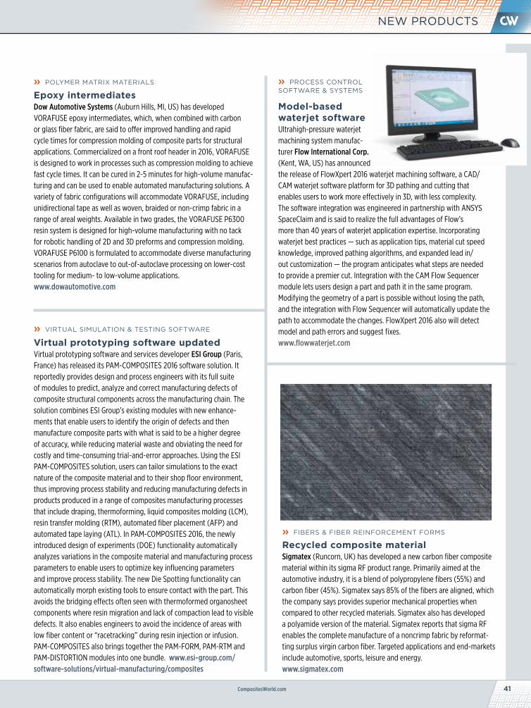
CompositesWorld.com 41
NEW PRODUCTS
» PROCESS CONTROL SOFTWARE & SYSTEMS
Model-based waterjet softwareUltrahigh-pressure waterjet machining system manufac-turer Flow International Corp. (Kent, WA, US) has announced the release of FlowXpert 2016 waterjet machining software, a CAD/CAM waterjet software platform for 3D pathing and cutting that enables users to work more effectively in 3D, with less complexity. The software integration was engineered in partnership with ANSYS SpaceClaim and is said to realize the full advantages of Flow’s more than 40 years of waterjet application expertise. Incorporating waterjet best practices — such as application tips, material cut speed knowledge, improved pathing algorithms, and expanded lead in/out customization — the program anticipates what steps are needed to provide a premier cut. Integration with the CAM Flow Sequencer module lets users design a part and path it in the same program. Modifying the geometry of a part is possible without losing the path, and the integration with Flow Sequencer will automatically update the path to accommodate the changes. FlowXpert 2016 also will detect model and path errors and suggest fixes.www.flowwaterjet.com
» POLYMER MATRIX MATERIALS
Epoxy intermediatesDow Automotive Systems (Auburn Hills, MI, US) has developed VORAFUSE epoxy intermediates, which, when combined with carbon or glass fiber fabric, are said to offer improved handling and rapid cycle times for compression molding of composite parts for structural applications. Commercialized on a front roof header in 2016, VORAFUSE is designed to work in processes such as compression molding to achieve fast cycle times. It can be cured in 2-5 minutes for high-volume manufac-turing and can be used to enable automated manufacturing solutions. A variety of fabric configurations will accommodate VORAFUSE, including unidirectional tape as well as woven, braided or non-crimp fabric in a range of areal weights. Available in two grades, the VORAFUSE P6300 resin system is designed for high-volume manufacturing with no tack for robotic handling of 2D and 3D preforms and compression molding. VORAFUSE P6100 is formulated to accommodate diverse manufacturing scenarios from autoclave to out-of-autoclave processing on lower-cost tooling for medium- to low-volume applications.www.dowautomotive.com
» VIRTUAL SIMULATION & TESTING SOFTWARE
Virtual prototyping software updatedVirtual prototyping software and services developer ESI Group (Paris, France) has released its PAM-COMPOSITES 2016 software solution. It reportedly provides design and process engineers with its full suite of modules to predict, analyze and correct manufacturing defects of composite structural components across the manufacturing chain. The solution combines ESI Group’s existing modules with new enhance-ments that enable users to identify the origin of defects and then manufacture composite parts with what is said to be a higher degree of accuracy, while reducing material waste and obviating the need for costly and time-consuming trial-and-error approaches. Using the ESI PAM-COMPOSITES solution, users can tailor simulations to the exact nature of the composite material and to their shop floor environment, thus improving process stability and reducing manufacturing defects in products produced in a range of composites manufacturing processes that include draping, thermoforming, liquid composites molding (LCM), resin transfer molding (RTM), automated fiber placement (AFP) and automated tape laying (ATL). In PAM-COMPOSITES 2016, the newly introduced design of experiments (DOE) functionality automatically analyzes variations in the composite material and manufacturing process parameters to enable users to optimize key influencing parameters and improve process stability. The new Die Spotting functionality can automatically morph existing tools to ensure contact with the part. This avoids the bridging effects often seen with thermoformed organosheet components where resin migration and lack of compaction lead to visible defects. It also enables engineers to avoid the incidence of areas with low fiber content or “racetracking” during resin injection or infusion. PAM-COMPOSITES also brings together the PAM-FORM, PAM-RTM and PAM-DISTORTION modules into one bundle. www.esi-group.com/software-solutions/virtual-manufacturing/composites
» FIBERS & FIBER REINFORCEMENT FORMS
Recycled composite materialSigmatex (Runcorn, UK) has developed a new carbon fiber composite material within its sigma RF product range. Primarily aimed at the automotive industry, it is a blend of polypropylene fibers (55%) and carbon fiber (45%). Sigmatex says 85% of the fibers are aligned, which the company says provides superior mechanical properties when compared to other recycled materials. Sigmatex also has developed a polyamide version of the material. Sigmatex reports that sigma RF enables the complete manufacture of a noncrimp fabric by reformat-ting surplus virgin carbon fiber. Targeted applications and end-markets include automotive, sports, leisure and energy. www.sigmatex.com
JANUARY 201742 CompositesWorld
MARKETPLACE
MANUFACTURING SUPPLIERS
TESTING
Blended Continuous Filament Thermoplastic and
Reinforcement Fibers for Composites
Contact Randy Spencer at 401-828-1100 ext 111 or
Available in various temperature ranges
800-762-1144 • 626-961-0211 • Fax 626-968-5140Website: http//:www.generalsealants.comE-mail: [email protected]
Used world wide by composite manufacturers
Distributed by:AIRTECH INTERNATIONAL INC.
Tel: (714) 899-8100 • Fax: (714) 899-8179Website: http//:www.airtechintl.com
Manufactured by:®
PO Box 3855, City of Industry, CA 91744
Ultrasonic C-Scan Inspection Systems for your
High Performance Materials
• Automated Ultrasonic C-Scan Systems for Simple and Complex Geometries• Multi-Axis Gantries and Immersion Tanks• System Upgrades
www.matec.comEmail: [email protected]
56 Hudson St., Northborough, MA 01532 • 508-351-3423
24305 Prielipp Road, Suite 102, Wildomar, CA 92595
RECRUITMENT/ HELP WANTED
www.forcomposites.comComposites Industry Recruiting and Placement
COMPOSITES SOURCESPhone (225) 273-4001 • Fax (225) 275-5807
P.O. Box 40086, Baton Rouge, LA 70835Email: [email protected]
SUBSCRIBE TODAY. compositesworld.com
CW is CompositesWorld!
Diamond and Solid Carbide • Technical Advice • Rotary Drills/Routers • C’sinks/Hole Saws • Stock and Specials
Designed For Compositeswww.starliteindustries.com800.727.1022 / 610.527.1300 VacuumTables.com • 773.725.4900
• Work Holding applications• Eliminates clamps/adhesives• Reduces set-up time• Retrofits all machines• OEMs and Dealers Wanted
Vacuum Tables for Composites
43
• Toughened system• Electrically isolating • Thermally conductive• Thermally conductive
Room Temperature CuringTWO COMPONENT EPOXY
Supreme 11AOHT
Tel: +1.201.343.8983 • www.masterbond.com
SHOWCASE / ADVERTISING INDEX
CompositesWorld.com
SHOWCASEADVERTISING INDEX
CINCINNATI
TESTING
LABORATORIES
A Subsidiary of Metcut Research Inc.
Machining & Testing of Advanced
Composite Materials
Email: [email protected]
1775 Carillon Blvd., Cincinnati, Ohio 45240Phone: 800/811-9220 • Fax: 513/851-3336
Comprehensive Testing Expertise• Mechanical • Physical • Thermal
• Enviromental • Fatigue MMC,CMC, & PMC Experience
A&P Technology Inc. . . . . . . . . . . . . . . . . . . . . . . . . . . . . . . . 5www.braider.com
Abaris Training . . . . . . . . . . . . . . . . . . . . . . . . . . . . . . . . . . . . 2www.abaris.com
C.R. Onsrud Inc.. . . . . . . . . . . . . . . . . . . . . . . . . . . . . . . . . . . 12www.cronsrud.com
CGTech . . . . . . . . . . . . . . . . . . . . . . . . . . . . . . . . . .Back Coverwww.cgtech.com
Coastal Enterprises Co. . . . . . . . . . . . . . . . . . . . . . . . . . . . . . 11www.precisionboard.com
Composites One LLC . . . . . . . . . . . . . . . Inside Front Coverwww.compositesone.com
Elliott Co. of Indianapolis Inc.. . . . . . . . . . . . . . . . . . . . . . . 15www.elliottfoam.com
Evonik . . . . . . . . . . . . . . . . . . . . . . . . . . . . . . . . . . . . . . . . . . . 17www.rohacell.com
IACMI. . . . . . . . . . . . . . . . . . . . . . . . . . . . . . . . . . . . . . . . . . . . . 7www.iacmi.org
Janicki Industries . . . . . . . . . . . . . . . . . . . . . . . . . . . . . . . . . 23www.janicki.com
Magnum Venus Products Inc. . . . . . . . . . . . . . . . . . . . . . . . 21www.mvpind.com
Material Testing Technology. . . . . . . . . . . . . . . . . . . . . . . . 31www.mttusa.net
McClean Anderson . . . . . . . . . . . . . . . . . . . . . . . . . . . . . . . . 38www.mccleananderson.com
North Coast Composites. . . . . . . . . . . . . . . . . . . . . . . . . . . 19www.northcoast.us
Pacific Coast Composites . . . . . . . . . . . . . . . . . . . . . . . . . . 16www.pccomposites.com
Shikoku International Corp. . . . . . . . . . . . . . . . . . . . . . . . . 29www.shikoku.co.jp
SME . . . . . . . . . . . . . . . . . . . . . . . . . . . . . . . . . . . . . . . . . . . . . . 9www.aerodefevent.com
Superior Tool Service Inc. . . . . . . . . . . . . . . . . . . . . . . . . . . 35www.superiortoolservice.com
Torr Technologies Inc. . . . . . . . . . . . . . . . . . . . . . . . . . . . . . . 2www.torrtech.com
Walton Process Technologies Inc. . . . . . . . . . . . . . . . . . . .20www.autoclaves.com
Wisconsin Oven Corp. . . . . . . . . . . . . . . . Inside Back Coverwww.wisoven.com
Wyoming Test Fixtures Inc.. . . . . . . . . . . . . . . . . . . . . . . . . 22www.wyomingtestfixtures.com
·Economical, polyester peel ply with good performance when used with both polyester & epoxy resins. ·Black tracers with high visibility to reduce the risk of peel ply being left on the part.
Econostitch® G
www.airtechonline.com
Airtech Composite Technology Ad.indd 1 12/8/11 3:05 PM
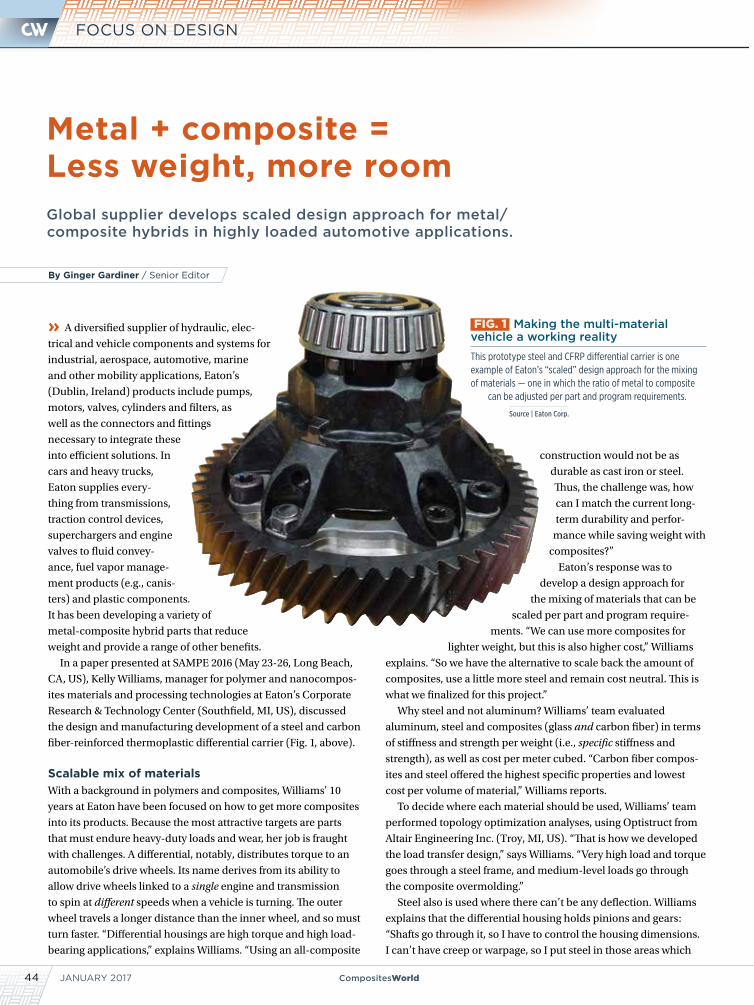
JANUARY 201744 CompositesWorld
FOCUS ON DESIGN
Metal + composite = Less weight, more room Global supplier develops scaled design approach for metal/ composite hybrids in highly loaded automotive applications.
» A diversified supplier of hydraulic, elec-
trical and vehicle components and systems for
industrial, aerospace, automotive, marine
and other mobility applications, Eaton’s
(Dublin, Ireland) products include pumps,
motors, valves, cylinders and filters, as
well as the connectors and fittings
necessary to integrate these
into efficient solutions. In
cars and heavy trucks,
Eaton supplies every-
thing from transmissions,
traction control devices,
superchargers and engine
valves to fluid convey-
ance, fuel vapor manage-
ment products (e.g., canis-
ters) and plastic components.
It has been developing a variety of
metal-composite hybrid parts that reduce
weight and provide a range of other benefits.
In a paper presented at SAMPE 2016 (May 23-26, Long Beach,
CA, US), Kelly Williams, manager for polymer and nanocompos-
ites materials and processing technologies at Eaton’s Corporate
Research & Technology Center (Southfield, MI, US), discussed
the design and manufacturing development of a steel and carbon
fiber-reinforced thermoplastic differential carrier (Fig. 1, above).
Scalable mix of materialsWith a background in polymers and composites, Williams’ 10
years at Eaton have been focused on how to get more composites
into its products. Because the most attractive targets are parts
that must endure heavy-duty loads and wear, her job is fraught
with challenges. A differential, notably, distributes torque to an
automobile’s drive wheels. Its name derives from its ability to
allow drive wheels linked to a single engine and transmission
to spin at different speeds when a vehicle is turning. The outer
wheel travels a longer distance than the inner wheel, and so must
turn faster. “Differential housings are high torque and high load-
bearing applications,” explains Williams. “Using an all-composite
construction would not be as
durable as cast iron or steel.
Thus, the challenge was, how
can I match the current long-
term durability and perfor-
mance while saving weight with
composites?”
Eaton’s response was to
develop a design approach for
the mixing of materials that can be
scaled per part and program require-
ments. “We can use more composites for
lighter weight, but this is also higher cost,” Williams
explains. “So we have the alternative to scale back the amount of
composites, use a little more steel and remain cost neutral. This is
what we finalized for this project.”
Why steel and not aluminum? Williams’ team evaluated
aluminum, steel and composites (glass and carbon fiber) in terms
of stiffness and strength per weight (i.e., specific stiffness and
strength), as well as cost per meter cubed. “Carbon fiber compos-
ites and steel offered the highest specific properties and lowest
cost per volume of material,” Williams reports.
To decide where each material should be used, Williams’ team
performed topology optimization analyses, using Optistruct from
Altair Engineering Inc. (Troy, MI, US). “That is how we developed
the load transfer design,” says Williams. “Very high load and torque
goes through a steel frame, and medium-level loads go through
the composite overmolding.”
Steel also is used where there can’t be any deflection. Williams
explains that the differential housing holds pinions and gears:
“Shafts go through it, so I have to control the housing dimensions.
I can’t have creep or warpage, so I put steel in those areas which
FIG. 1 Making the multi-material vehicle a working reality
This prototype steel and CFRP differential carrier is one example of Eaton’s “scaled” design approach for the mixing of materials — one in which the ratio of metal to composite
can be adjusted per part and program requirements.
Source | Eaton Corp.
By Ginger Gardiner / Senior Editor
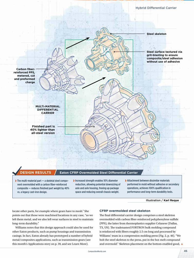
45CompositesWorld.com
Carbon fiber-reinforced PPS,
metered, cut and preformed
charge
Hybrid Differential Carrier
Metal + composite = Less weight, more room
locate other parts, for example where gears have to mesh.” She
points out that those were machined locations in any case, “so we
left them metal, and we also left wear surfaces in steel to maintain
long-term durability.”
Williams notes that this design approach could also be used for
other Eaton products, such as pump housings and transmission
casings. In fact, Eaton already has prototyped a number of hybrid
metal/composites applications, such as transmission gears (see
this month’s Applications story on p. 39, and see Learn More).
Illustration / Karl Reque
Eaton CFRP Overmolded Steel Differential Carrier
› The multi-material part — a skeletal steel compo-nent overmolded with a carbon fiber-reinforced composite — reduces finished part weight by 40% vs. a legacy cast-iron design.
› Increased strength enables 10% diameter reduction, allowing potential downsizing of axle and axle housing, freeing up package space and reducing overall chassis weight.
› Attachment between dissimilar materials performed in mold without adhesive or secondary operations, achieves 100% qualification in performance and long-term durability tests.
CFRP overmolded steel skeletonThe final differential carrier design comprises a steel skeleton
overmolded with carbon fiber-reinforced polyphenylene sulfide
(PPS), the latter from thermoplastics supplier Celanese (Dallas,
TX, US). The tradenamed FORTRON bulk molding compound
is reinforced with fibers roughly 2.5 cm long and processed by
Williams’ team in a compression molding press (Fig. 2, p. 46). “We
bolt the steel skeleton to the press, put in the hot-melt compound
and overmold.” Skeleton placement on the bottom enabled good,
Steel skeleton
Steel surface textured via grit-blasting to ensure composite/steel adhesion without use of adhesive
MULTI-MATERIAL DIFFERENTIAL
CARRIER
Finished part is 40% lighter than all-steel version
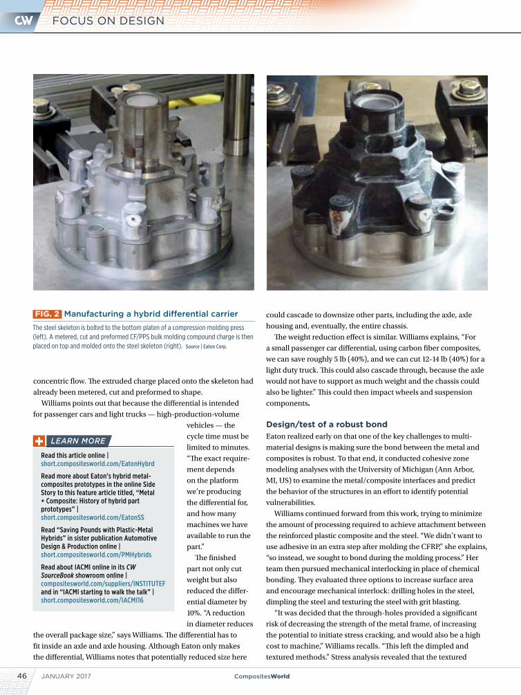
JANUARY 201746 CompositesWorld
FOCUS ON DESIGN
concentric flow. The extruded charge placed onto the skeleton had
already been metered, cut and preformed to shape.
Williams points out that because the differential is intended
for passenger cars and light trucks — high-production-volume
vehicles — the
cycle time must be
limited to minutes.
“The exact require-
ment depends
on the platform
we’re producing
the differential for,
and how many
machines we have
available to run the
part.”
The finished
part not only cut
weight but also
reduced the differ-
ential diameter by
10%. “A reduction
in diameter reduces
the overall package size,” says Williams. The differential has to
fit inside an axle and axle housing. Although Eaton only makes
the differential, Williams notes that potentially reduced size here
could cascade to downsize other parts, including the axle, axle
housing and, eventually, the entire chassis.
The weight reduction effect is similar. Williams explains, “For
a small passenger car differential, using carbon fiber composites,
we can save roughly 5 lb (40%), and we can cut 12-14 lb (40%) for a
light duty truck. This could also cascade through, because the axle
would not have to support as much weight and the chassis could
also be lighter.” This could then impact wheels and suspension
components.
Design/test of a robust bondEaton realized early on that one of the key challenges to multi-
material designs is making sure the bond between the metal and
composites is robust. To that end, it conducted cohesive zone
modeling analyses with the University of Michigan (Ann Arbor,
MI, US) to examine the metal/composite interfaces and predict
the behavior of the structures in an effort to identify potential
vulnerabilities.
Williams continued forward from this work, trying to minimize
the amount of processing required to achieve attachment between
the reinforced plastic composite and the steel. “We didn’t want to
use adhesive in an extra step after molding the CFRP,” she explains,
“so instead, we sought to bond during the molding process.” Her
team then pursued mechanical interlocking in place of chemical
bonding. They evaluated three options to increase surface area
and encourage mechanical interlock: drilling holes in the steel,
dimpling the steel and texturing the steel with grit blasting.
“It was decided that the through-holes provided a significant
risk of decreasing the strength of the metal frame, of increasing
the potential to initiate stress cracking, and would also be a high
cost to machine,” Williams recalls. “This left the dimpled and
textured methods.” Stress analysis revealed that the textured
FIG. 2 Manufacturing a hybrid differential carrier
The steel skeleton is bolted to the bottom platen of a compression molding press (left). A metered, cut and preformed CF/PPS bulk molding compound charge is then placed on top and molded onto the steel skeleton (right). Source | Eaton Corp.
Read this article online | short.compositesworld.com/EatonHybrd
Read more about Eaton’s hybrid metal-composites prototypes in the online Side Story to this feature article titled, “Metal + Composite: History of hybrid part prototypes” | short.compositesworld.com/EatonSS
Read “Saving Pounds with Plastic-Metal Hybrids” in sister publication Automotive Design & Production online | short.compositesworld.com/PMHybrids
Read about IACMI online in its CW SourceBook showroom online | compositesworld.com/suppliers/INSTITUTEF and in “IACMI starting to walk the talk” | short.compositesworld.com/IACMI16
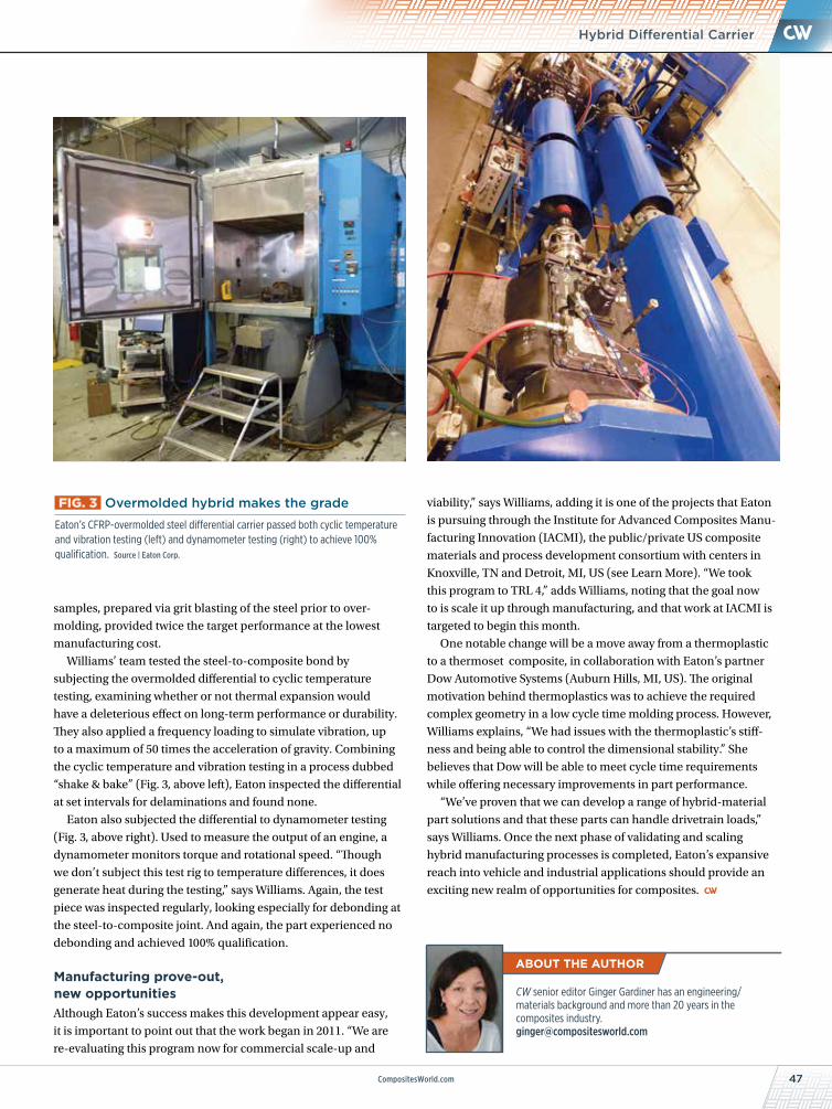
47CompositesWorld.com
samples, prepared via grit blasting of the steel prior to over-
molding, provided twice the target performance at the lowest
manufacturing cost.
Williams’ team tested the steel-to-composite bond by
subjecting the overmolded differential to cyclic temperature
testing, examining whether or not thermal expansion would
have a deleterious effect on long-term performance or durability.
They also applied a frequency loading to simulate vibration, up
to a maximum of 50 times the acceleration of gravity. Combining
the cyclic temperature and vibration testing in a process dubbed
“shake & bake” (Fig. 3, above left), Eaton inspected the differential
at set intervals for delaminations and found none.
Eaton also subjected the differential to dynamometer testing
(Fig. 3, above right). Used to measure the output of an engine, a
dynamometer monitors torque and rotational speed. “Though
we don’t subject this test rig to temperature differences, it does
generate heat during the testing,” says Williams. Again, the test
piece was inspected regularly, looking especially for debonding at
the steel-to-composite joint. And again, the part experienced no
debonding and achieved 100% qualification.
Manufacturing prove-out, new opportunitiesAlthough Eaton’s success makes this development appear easy,
it is important to point out that the work began in 2011. “We are
re-evaluating this program now for commercial scale-up and
Hybrid Differential Carrier
FIG. 3 Overmolded hybrid makes the grade
Eaton’s CFRP-overmolded steel differential carrier passed both cyclic temperature and vibration testing (left) and dynamometer testing (right) to achieve 100% qualification. Source | Eaton Corp.
viability,” says Williams, adding it is one of the projects that Eaton
is pursuing through the Institute for Advanced Composites Manu-
facturing Innovation (IACMI), the public/private US composite
materials and process development consortium with centers in
Knoxville, TN and Detroit, MI, US (see Learn More). “We took
this program to TRL 4,” adds Williams, noting that the goal now
to is scale it up through manufacturing, and that work at IACMI is
targeted to begin this month.
One notable change will be a move away from a thermoplastic
to a thermoset composite, in collaboration with Eaton’s partner
Dow Automotive Systems (Auburn Hills, MI, US). The original
motivation behind thermoplastics was to achieve the required
complex geometry in a low cycle time molding process. However,
Williams explains, “We had issues with the thermoplastic’s stiff-
ness and being able to control the dimensional stability.” She
believes that Dow will be able to meet cycle time requirements
while offering necessary improvements in part performance.
“We’ve proven that we can develop a range of hybrid-material
part solutions and that these parts can handle drivetrain loads,”
says Williams. Once the next phase of validating and scaling
hybrid manufacturing processes is completed, Eaton’s expansive
reach into vehicle and industrial applications should provide an
exciting new realm of opportunities for composites.
CW senior editor Ginger Gardiner has an engineering/materials background and more than 20 years in the composites industry. [email protected]
THE NEW additivemanufacturing.media
Additive Manufacturing for Industrial Parts Production
VISIT US TODAY AT: additivemanufacturing.media
A P R O P E R T Y O F:
Get Connected! • Industry Trends • Technical Articles • New Products
• Suppliers Directory
EXPANDED COVERAGE Fresh coverage from the Additive Manufacturing Blog keeps you up- to-date on all the latest AM news & trends!
ENHANCEDDESIGN More product images and reorganized supplier directory, helping you find the information you need fast!
IMPROVED NAVIGATION Optimized search and navigation make it easier to research and explore the products, processes and suppliers you need!
AM_NEWwebsite_full_univ.indd 1 12/20/16 12:08 PM
0117 Wisconsin Oven.indd 1 12/13/16 1:46 PM
CW-Ad_CGTech-FullPage-2015.indd 1 4/1/2015 12:01:27 PM