Embed Size (px)
Citation preview
1 | PIR Ready VT7600 Series-Installation Guide 028-0363-02
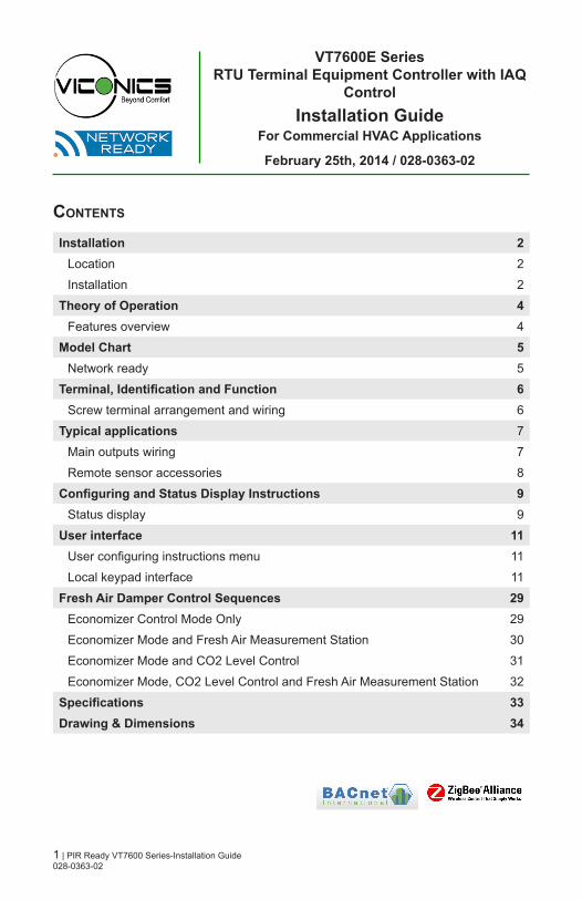
Contents
Installation 2Location 2
Installation 2
Theory of Operation 4Features overview 4
Model Chart 5Network ready 5
Terminal, Identification and Function 6Screw terminal arrangement and wiring 6
Typical applications 7
Main outputs wiring 7
Remote sensor accessories 8
Configuring and Status Display Instructions 9Status display 9
User interface 11User configuring instructions menu 11
Local keypad interface 11
Fresh Air Damper Control Sequences 29Economizer Control Mode Only 29
Economizer Mode and Fresh Air Measurement Station 30
Economizer Mode and CO2 Level Control 31
Economizer Mode, CO2 Level Control and Fresh Air Measurement Station 32
Specifications 33Drawing & Dimensions 34
VT7600E SeriesRTU Terminal Equipment Controller with IAQ
ControlInstallation Guide
For Commercial HVAC Applications
February 25th, 2014 / 028-0363-02

2 | PIR Ready VT7600 Series-Installation Guide 028-0363-02
Fig. 1
InstallatIonRemove the security screw on the bottom of Terminal Equipment Controller cover.
• Open unit by pulling on the bottom side of Terminal Equipment Controller (Fig. 1).
• Remove wiring terminals from sticker.
• Please read the FCC ID and IC label installed in the cover upon removal of cover for the wireless products.
Location
1. Should not be installed on an outside wall.
2. Must be installed away from any direct heat source.
3. Should not be installed near an air discharge grill.
4. Should not be affected by direct sun radiation.
5. Nothing should restrict vertical air circulation to the Terminal Equipment Controller.
Installation
1. Swing open the Terminal Equipment Controller PCB to the left by pressing the PCB locking tabs (Fig. 2).
2. Pull out cables 6” out from the wall.
3. Wall surface must be flat and clean.
4. Insert cable in the central hole of the base.
5. Align the base and mark the location of the two mounting holes on the wall. Install proper side of base up.
6. Install anchors in the wall.
7. Insert screws in mounting holes on each side of the base (Fig. 2).
8. Gently swing back the circuit board on the base and push on it until the tabs lock it.
9. Strip each wire 1/4 inch from end.
Location of PCB retaining tabs
Fig. 2
Re-install terminal blocks
Fig. 3

3 | PIR Ready VT7600 Series-Installation Guide 028-0363-02
• If replacing an existing Terminal Equipment Controller, label the wires before removal of the Terminal Equipment Controller.
• Electronic controls are static sensitive devices. Discharge yourself properly before manipulating and installing the Terminal Equipment Controller.
• A short circuit or wrong wiring may permanently damage the Terminal Equipment Controller or the equipment.
• All VT7000 series Terminal Equipment Controllers are designed for use as operating controls only and are not safety devices. These instruments have undergone rigorous tests and verification prior to shipping to ensure proper and reliable operation in the field. Whenever a control failure could lead to personal injury and/or loss of property, it becomes the responsibility of the user / installer / electrical system designer to incorporate safety devices (such as relays, flow switch, thermal protections, etc…) and/or an alarm system to protect the entire system against such catastrophic failures. Tampering with the devices or unintended application of the devices will result in a void of warranty.
10. Insert each wire according to wiring diagram.
11. Gently push excess wiring back into hole (Fig. 3).
12. Re-Install wiring terminals in their correct locations (Fig. 3).
13. Re-install the cover (top side first) and gently push extra wire length back into the hole in the wall.
14. Install security screw.

4 | PIR Ready VT7600 Series-Installation Guide 028-0363-02
Theory of operaTion The VT76X6E series uses a Viconics proprietary adaptive logic algorithm to control the space temperature. This algorithm controls the heating or air conditioning system to minimize overshoot while still providing comfort. It provides exceptional accuracy due to its unique PI time proportioning control algorithm, which virtually eliminates temperature offset associated with traditional, differential-based On-Off thermostats.
Fig.2 - On-Off mechanical control vs PI electronic control.
Features overview • 7 day schedule models, 2 or 4 events.• C02 control logic based on fresh air volume or fresh air damper position.• Fresh air damper output for building CO2 level control.• Gas, oil or electric system compatibility. • Remote outdoor sensing capability for added flexibility.
- System mode heating and cooling lockout.• Remote discharge air sensor input for monitoring and control purpose.
- System efficiency feedback. - Discharge high limit heating lockout. - Discharge low limit cooling lockout.
• Remote return air sensor input that replaces internal on board sensor. - System efficiency feedback.
• Password protected configuration menu and lockable keypads for security.• Automatic smart fan operation saves energy during unoccupied periods.• Non volatile EEPROM memory prevents loss of parameters during power short-
age.• Configurable SPST output relay on scheduling models for lighting, exhaust fan or
fresh air control.• 6 hour typical reserve time for clock in case of power loss.Easy configuration and self-binding operation• Easy configuration without using any special software or additional tools.• Can be used as stand-alone or with BACnet™ MS-TP supervision controller for
monitoring purposed.• Truly scalable in terms of supported number of zones and RTU units.
5 | PIR Ready VT7600 Series-Installation Guide 028-0363-02
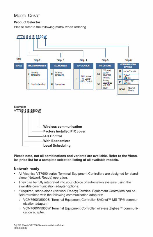
Model CharT
Product SelectorPlease refer to the following matrix when ordering
Please note, not all combinations and variants are available. Refer to the Vicon-ics price list for a complete selection listing of all available models.
Network ready• All Viconics VT7600 series Terminal Equipment Controllers are designed for stand-
alone (Network Ready) operation. • They can be fully integrated into your choice of automation systems using the
available communication adapter options. • If required, stand-alone (Network Ready) Terminal Equipment Controllers can be
field retrofitted with the following communication adapters: VCM7600N5000B, Terminal Equipment Controller BACnet™ MS-TP® commu-
nication adapter. VCM7600N5000W Terminal Equipment Controller wireless Zigbee™ communi-
cation adapter.
Example:VT765 6 E 5500W
Wireless communicationFactory installed PIR coverIAQ ControlWith EconomizerLocal Scheduling
6 | PIR Ready VT7600 Series-Installation Guide 028-0363-02
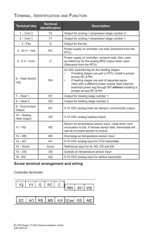
TerMinal, idenTifiCaTion and funCTion
Terminal Use Terminal Identification Description
1 – Cool 2 Y2 Output for cooling / compressor stage number 2.
2 – Cool 1 Y1 Output for cooling / compressor stage number 1.
3 - Fan G Output for the fan.
4 - 24 V ~ Hot RC Power supply of controller, hot side (Delivered from the RTU).
5 - 0 V ~ Com CPower supply of controller, common side. Also used as reference for the analog BPD output when used (Delivered from the RTU).
6 – Heat Switch Leg RH
24 VAC switched leg for the heating stages.• If heating stages are part or RTU, install a jumper
across RC & RH.• If heating stages are part of separate equip-
ment with a different power supply, feed external switched power leg through RH without installing a jumper across RC & RH.
7 – Heat 1 W1 Output for heating stage number 1.
8 – Heat 2 W2 Output for heating stage number 2.
9 – Economizer Output EC 0-10 VDC analog fresh air damper / economizer output.
10 – Analog Heat Output AO 0-10 VDC analog heating output.
11 – RS RSReturn air temperature sensor input. Used when com-munication is lost. If remote sensor fails, thermostat will use its on-board sensor to control.
12 – MS MS Discharge air temperature sensor input
13 – AI1 AI1 0-10 VDC analog input for CO2 transmitter
14 – Scom Scom Reference input for AI, RS, OS and DS
15 – OS OS Outside air temperature sensor input
16 –AI2 AI2 0-10 VDC analog input for airflow transmitter
Screw terminal arrangement and wiring
Controller terminals:
7 | PIR Ready VT7600 Series-Installation Guide 028-0363-02
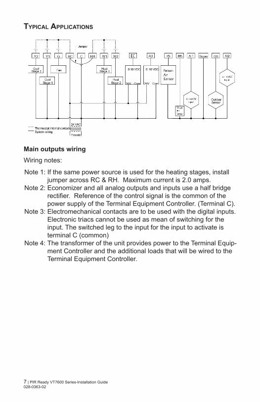
typIcal applIcatIons
Main outputs wiring Wiring notes:
Note 1: If the same power source is used for the heating stages, install jumper across RC & RH. Maximum current is 2.0 amps.
Note 2: Economizer and all analog outputs and inputs use a half bridge rectifier. Reference of the control signal is the common of the power supply of the Terminal Equipment Controller. (Terminal C).
Note 3: Electromechanical contacts are to be used with the digital inputs. Electronic triacs cannot be used as mean of switching for the input. The switched leg to the input for the input to activate is terminal C (common)
Note 4: The transformer of the unit provides power to the Terminal Equip-ment Controller and the additional loads that will be wired to the Terminal Equipment Controller.
8 | PIR Ready VT7600 Series-Installation Guide 028-0363-02
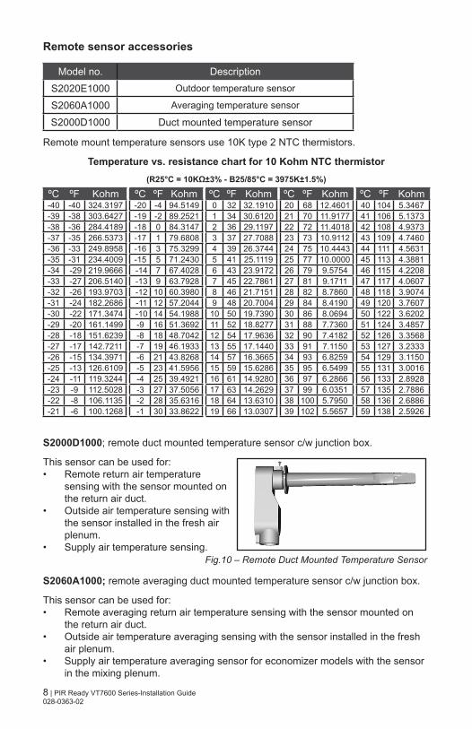
Remote sensor accessories
Model no. Description
S2020E1000 Outdoor temperature sensor
S2060A1000 Averaging temperature sensor
S2000D1000 Duct mounted temperature sensor
Remote mount temperature sensors use 10K type 2 NTC thermistors.
Temperature vs. resistance chart for 10 Kohm NTC thermistor (R25°C = 10KΩ±3% - B25/85°C = 3975K±1.5%)
ºC ºF Kohm ºC ºF Kohm ºC ºF Kohm ºC ºF Kohm ºC ºF Kohm-40 -40 324.3197 -20 -4 94.5149 0 32 32.1910 20 68 12.4601 40 104 5.3467-39 -38 303.6427 -19 -2 89.2521 1 34 30.6120 21 70 11.9177 41 106 5.1373-38 -36 284.4189 -18 0 84.3147 2 36 29.1197 22 72 11.4018 42 108 4.9373-37 -35 266.5373 -17 1 79.6808 3 37 27.7088 23 73 10.9112 43 109 4.7460-36 -33 249.8958 -16 3 75.3299 4 39 26.3744 24 75 10.4443 44 111 4.5631-35 -31 234.4009 -15 5 71.2430 5 41 25.1119 25 77 10.0000 45 113 4.3881-34 -29 219.9666 -14 7 67.4028 6 43 23.9172 26 79 9.5754 46 115 4.2208-33 -27 206.5140 -13 9 63.7928 7 45 22.7861 27 81 9.1711 47 117 4.0607-32 -26 193.9703 -12 10 60.3980 8 46 21.7151 28 82 8.7860 48 118 3.9074-31 -24 182.2686 -11 12 57.2044 9 48 20.7004 29 84 8.4190 49 120 3.7607-30 -22 171.3474 -10 14 54.1988 10 50 19.7390 30 86 8.0694 50 122 3.6202-29 -20 161.1499 -9 16 51.3692 11 52 18.8277 31 88 7.7360 51 124 3.4857-28 -18 151.6239 -8 18 48.7042 12 54 17.9636 32 90 7.4182 52 126 3.3568-27 -17 142.7211 -7 19 46.1933 13 55 17.1440 33 91 7.1150 53 127 3.2333-26 -15 134.3971 -6 21 43.8268 14 57 16.3665 34 93 6.8259 54 129 3.1150-25 -13 126.6109 -5 23 41.5956 15 59 15.6286 35 95 6.5499 55 131 3.0016-24 -11 119.3244 -4 25 39.4921 16 61 14.9280 36 97 6.2866 56 133 2.8928-23 -9 112.5028 -3 27 37.5056 17 63 14.2629 37 99 6.0351 57 135 2.7886-22 -8 106.1135 -2 28 35.6316 18 64 13.6310 38 100 5.7950 58 136 2.6886-21 -6 100.1268 -1 30 33.8622 19 66 13.0307 39 102 5.5657 59 138 2.5926
S2000D1000; remote duct mounted temperature sensor c/w junction box.
This sensor can be used for:• Remote return air temperature
sensing with the sensor mounted on the return air duct.
• Outside air temperature sensing with the sensor installed in the fresh air plenum.
• Supply air temperature sensing.
S2060A1000; remote averaging duct mounted temperature sensor c/w junction box.
This sensor can be used for:• Remote averaging return air temperature sensing with the sensor mounted on
the return air duct.• Outside air temperature averaging sensing with the sensor installed in the fresh
air plenum.• Supply air temperature averaging sensor for economizer models with the sensor
in the mixing plenum.
Fig.10 – Remote Duct Mounted Temperature Sensor
9 | PIR Ready VT7600 Series-Installation Guide 028-0363-02
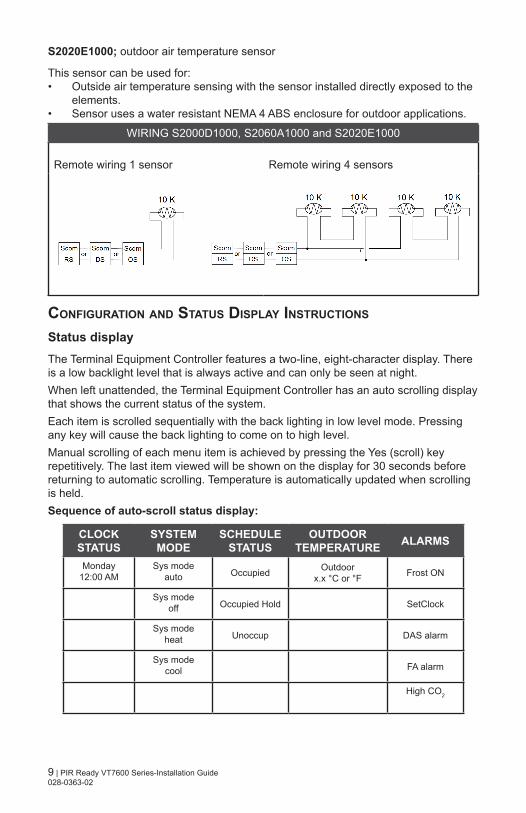
S2020E1000; outdoor air temperature sensor
This sensor can be used for:• Outside air temperature sensing with the sensor installed directly exposed to the
elements. • Sensor uses a water resistant NEMA 4 ABS enclosure for outdoor applications.
WIRING S2000D1000, S2060A1000 and S2020E1000
Remote wiring 1 sensor Remote wiring 4 sensors
confIguratIon and status dIsplay InstructIons
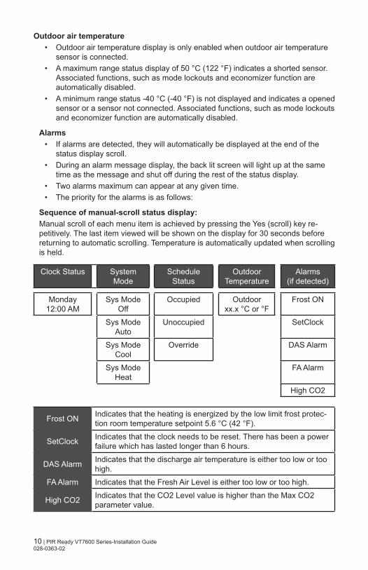
Status displayThe Terminal Equipment Controller features a two-line, eight-character display. There is a low backlight level that is always active and can only be seen at night.When left unattended, the Terminal Equipment Controller has an auto scrolling display that shows the current status of the system. Each item is scrolled sequentially with the back lighting in low level mode. Pressing any key will cause the back lighting to come on to high level. Manual scrolling of each menu item is achieved by pressing the Yes (scroll) key repetitively. The last item viewed will be shown on the display for 30 seconds before returning to automatic scrolling. Temperature is automatically updated when scrolling is held.Sequence of auto-scroll status display:
CLOCK STATUS
SYSTEM MODE
SCHEDULE STATUS
OUTDOOR TEMPERATURE ALARMS
Monday12:00 AM
Sys modeauto Occupied Outdoor
x.x °C or °F Frost ON
Sys modeoff Occupied Hold SetClock
Sys modeheat Unoccup DAS alarm
Sys modecool FA alarm
High CO2
10 | PIR Ready VT7600 Series-Installation Guide 028-0363-02
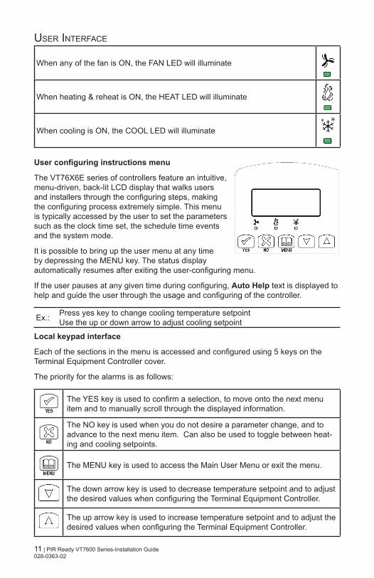
Outdoor air temperature • Outdoor air temperature display is only enabled when outdoor air temperature
sensor is connected.• A maximum range status display of 50 °C (122 °F) indicates a shorted sensor.
Associated functions, such as mode lockouts and economizer function are automatically disabled.
• A minimum range status -40 °C (-40 °F) is not displayed and indicates a opened sensor or a sensor not connected. Associated functions, such as mode lockouts and economizer function are automatically disabled.
Alarms• If alarms are detected, they will automatically be displayed at the end of the
status display scroll. • During an alarm message display, the back lit screen will light up at the same
time as the message and shut off during the rest of the status display. • Two alarms maximum can appear at any given time. • The priority for the alarms is as follows:
Sequence of manual-scroll status display:Manual scroll of each menu item is achieved by pressing the Yes (scroll) key re-petitively. The last item viewed will be shown on the display for 30 seconds before returning to automatic scrolling. Temperature is automatically updated when scrolling is held.
Clock Status SystemMode
ScheduleStatus
OutdoorTemperature
Alarms(if detected)
Monday12:00 AM
Sys Mode Off
Occupied Outdoorxx.x °C or °F
Frost ON
Sys Mode Auto
Unoccupied SetClock
Sys Mode Cool
Override DAS Alarm
Sys Mode Heat
FA Alarm
High CO2
Frost ON Indicates that the heating is energized by the low limit frost protec-tion room temperature setpoint 5.6 °C (42 °F).
SetClock Indicates that the clock needs to be reset. There has been a power failure which has lasted longer than 6 hours.
DAS Alarm Indicates that the discharge air temperature is either too low or too high.
FA Alarm Indicates that the Fresh Air Level is either too low or too high.
High CO2 Indicates that the CO2 Level value is higher than the Max CO2 parameter value.
11 | PIR Ready VT7600 Series-Installation Guide 028-0363-02
user inTerfaCe
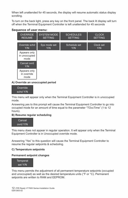
When any of the fan is ON, the FAN LED will illuminate
When heating & reheat is ON, the HEAT LED will illuminate
When cooling is ON, the COOL LED will illuminate
User configuring instructions menu
The VT76X6E series of controllers feature an intuitive, menu-driven, back-lit LCD display that walks users and installers through the configuring steps, making the configuring process extremely simple. This menu is typically accessed by the user to set the parameters such as the clock time set, the schedule time events and the system mode.
It is possible to bring up the user menu at any time by depressing the MENU key. The status display automatically resumes after exiting the user-configuring menu.
If the user pauses at any given time during configuring, Auto Help text is displayed to help and guide the user through the usage and configuring of the controller.
Ex.: Press yes key to change cooling temperature setpointUse the up or down arrow to adjust cooling setpoint
Local keypad interface
Each of the sections in the menu is accessed and configured using 5 keys on the Terminal Equipment Controller cover.
The priority for the alarms is as follows:
The YES key is used to confirm a selection, to move onto the next menu item and to manually scroll through the displayed information.
The NO key is used when you do not desire a parameter change, and to advance to the next menu item. Can also be used to toggle between heat-ing and cooling setpoints.
The MENU key is used to access the Main User Menu or exit the menu.
The down arrow key is used to decrease temperature setpoint and to adjust the desired values when configuring the Terminal Equipment Controller.
The up arrow key is used to increase temperature setpoint and to adjust the desired values when configuring the Terminal Equipment Controller.
12 | PIR Ready VT7600 Series-Installation Guide 028-0363-02
When left unattended for 45 seconds, the display will resume automatic status display scrolling.
To turn on the back light, press any key on the front panel. The back lit display will turn off when the Terminal Equipment Controller is left unattended for 45 seconds
Sequence of user menu:OVERRIDE RESUME
SYSTEM MODE SETTING
SCHEDULES SETTING
CLOCK SETTING
Override schd Y/N
Sys mode setY/N
Schedule setY/N
Clock setY/N
Appears only in unoccupied
mode
Cancel ovrd Y/N
Appears only in override
mode
A) Override an unoccupied period
Overrideschd Y/N
This menu will appear only when the Terminal Equipment Controller is in unoccupied mode. Answering yes to this prompt will cause the Terminal Equipment Controller to go into occupied mode for an amount of time equal to the parameter “TOccTime” (1 to 12 hours).B) Resume regular scheduling
Cancelovrd Y/N
This menu does not appear in regular operation. It will appear only when the Terminal Equipment Controller is in Unoccupied override mode.
Answering “Yes” to this question will cause the Terminal Equipment Controller to resume the regular setpoints & scheduling.
C) Temperature setpoints
Permanent setpoint changes
Temperatset Y/N
This menu permits the adjustment of all permanent temperature setpoints (occupied and unoccupied) as well as the desired temperature units (°F or °C). Permanent setpoints are written to RAM and EEPROM.
13 | PIR Ready VT7600 Series-Installation Guide 028-0363-02
Cooling setpoint
Occupied mode
Heating setpoint
Occupied mode
Cooling setpoint
Unoccupied mode
Heating setpoint
Unoccupied mode
°F or °C display setting
Coolingset? Y/N
No next →Yes down
↓
Heatingset? Y/N
No next →Yes down
↓
Unocc CLset? Y/N
No next →Yes down
↓
Unocc HTset? Y/N
No next →Yes down
↓
°F or °Cset? Y/N
No next →Yes down
↓Use keys to set value, Yes key to confirm
Cooling70.0 °F
Use To set value
Heating68.00 °F
Use To set value
Unocc CL
80.0 °F
Use To set value
Unocc HT
60.0 °F
Use To set value
Units°F
Use To set value
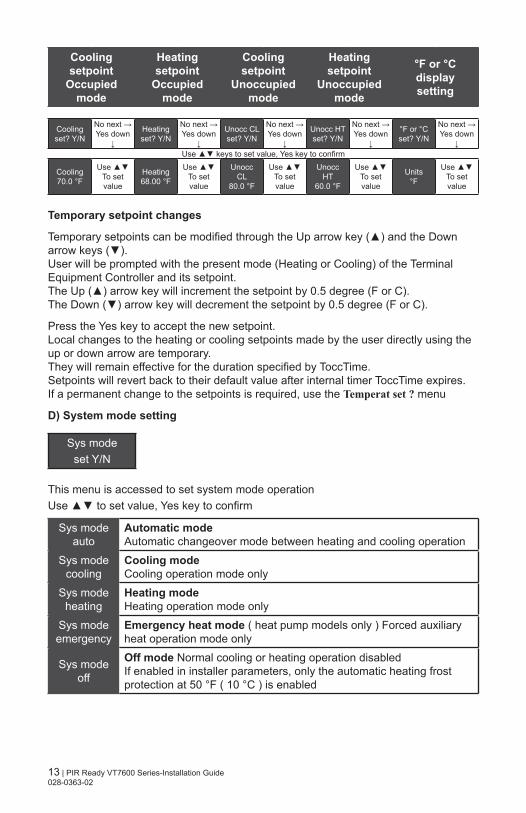
Temporary setpoint changes
Temporary setpoints can be modified through the Up arrow key () and the Down arrow keys ().User will be prompted with the present mode (Heating or Cooling) of the Terminal Equipment Controller and its setpoint.The Up () arrow key will increment the setpoint by 0.5 degree (F or C).The Down () arrow key will decrement the setpoint by 0.5 degree (F or C).
Press the Yes key to accept the new setpoint.Local changes to the heating or cooling setpoints made by the user directly using the up or down arrow are temporary.They will remain effective for the duration specified by ToccTime.Setpoints will revert back to their default value after internal timer ToccTime expires.If a permanent change to the setpoints is required, use the Temperat set ? menu
D) System mode setting
Sys modeset Y/N
This menu is accessed to set system mode operationUse to set value, Yes key to confirm
Sys mode auto
Automatic modeAutomatic changeover mode between heating and cooling operation
Sys mode cooling
Cooling mode Cooling operation mode only
Sys mode heating
Heating mode Heating operation mode only
Sys mode emergency
Emergency heat mode ( heat pump models only ) Forced auxiliary heat operation mode only
Sys mode off
Off mode Normal cooling or heating operation disabled If enabled in installer parameters, only the automatic heating frost protection at 50 °F ( 10 °C ) is enabled
14 | PIR Ready VT7600 Series-Installation Guide 028-0363-02
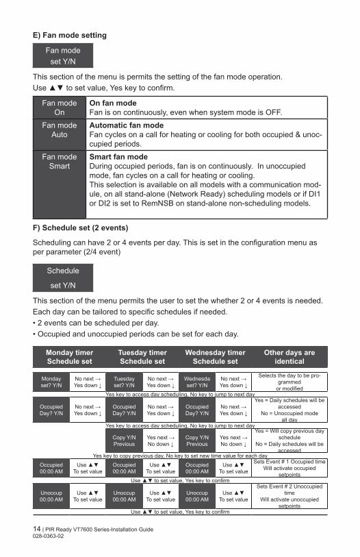
E) Fan mode setting
Fan modeset Y/N
This section of the menu is permits the setting of the fan mode operation.Use to set value, Yes key to confirm.
Fan mode On
On fan mode Fan is on continuously, even when system mode is OFF.
Fan mode Auto
Automatic fan modeFan cycles on a call for heating or cooling for both occupied & unoc-cupied periods.
Fan mode Smart
Smart fan mode During occupied periods, fan is on continuously. In unoccupied mode, fan cycles on a call for heating or cooling. This selection is available on all models with a communication mod-ule, on all stand-alone (Network Ready) scheduling models or if DI1 or DI2 is set to RemNSB on stand-alone non-scheduling models.
F) Schedule set (2 events)
Scheduling can have 2 or 4 events per day. This is set in the configuration menu as per parameter (2/4 event)
Schedule
set Y/N
This section of the menu permits the user to set the whether 2 or 4 events is needed.Each day can be tailored to specific schedules if needed.• 2 events can be scheduled per day.• Occupied and unoccupied periods can be set for each day.
Monday timer Schedule set
Tuesday timer Schedule set
Wednesday timer Schedule set
Other days are identical
Mondayset? Y/N
No next →Yes down ↓
Tuesdayset? Y/N
No next →Yes down ↓
Wednesdaset? Y/N
No next →Yes down ↓
Selects the day to be pro-grammed
or modifiedYes key to access day scheduling, No key to jump to next day
OccupiedDay? Y/N
No next →Yes down ↓
OccupiedDay? Y/N
No next →Yes down ↓
OccupiedDay? Y/N
No next →Yes down ↓
Yes = Daily schedules will be accessed
No = Unoccupied mode all day
Yes key to access day scheduling, No key to jump to next day
Copy Y/NPrevious
Yes next →No down ↓
Copy Y/NPrevious
Yes next →No down ↓
Yes = Will copy previous day schedule
No = Daily schedules will be accessed
Yes key to copy previous day, No key to set new time value for each dayOccupied00:00 AM
Use To set value
Occupied00:00 AM
Use To set value
Occupied00:00 AM
Use To set value
Sets Event # 1 Occupied timeWill activate occupied
setpointsUse to set value, Yes key to confirm
Unoccup00:00 AM
Use To set value
Unoccup00:00 AM
Use To set value
Unoccup00:00 AM
Use To set value
Sets Event # 2 Unoccupied time
Will activate unoccupied setpoints
Use to set value, Yes key to confirm
15 | PIR Ready VT7600 Series-Installation Guide 028-0363-02
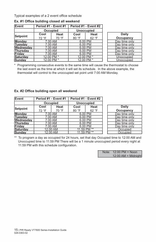
Typical examples of a 2 event office scheduleEx. #1 Office building closed all weekendEvent Period #1 - Event #1 Period #1 - Event #2
Occupied Unoccupied
Setpoint Cool72 °F
Heat70 °F
Cool80 °F
Heat62 °F
DailyOccupancy
Monday 7.00 AM 6.00 PM Day time onlyTuesday 7.00 AM 6.00 PM Day time onlyWednesday 7.00 AM 6.00 PM Day time onlyThursday 7.00 AM 6.00 PM Day time onlyFriday 7.00 AM 6.00 PM Day time onlySaturday 12.00 PM * 12.00 PM * UnoccupiedSunday 12.00 PM * 12.00 PM * Unoccupied * Programming consecutive events to the same time will cause the thermostat to choose
the last event as the time at which it will set its schedule. In the above example, the thermostat will control to the unoccupied set point until 7:00 AM Monday.
Ex. #2 Office building open all weekend
Event Period #1 - Event #1 Period #1 - Event #2Occupied Unoccupied
Setpoint Cool72 °F
Heat70 °F
Cool80 °F
Heat62 °F
DailyOccupancy
Monday 7.00 AM 6.00 PM Day time onlyTuesday 7.00 AM 6.00 PM Day time onlyWednesday 7.00 AM 6.00 PM Day time onlyThursday 7.00 AM 6.00 PM Day time onlyFriday 7.00 AM 6.00 PM Day time onlySaturday 12.00 AM 11.59 PM ** OccupiedSunday 12.00 AM 11.59 PM ** Occupied** To program a day as occupied for 24 hours, set that day Occupied time to 12:00 AM and
Unoccupied time to 11:59 PM There will be a 1 minute unoccupied period every night at 11:59 PM with this schedule configuration.
Note: 12:00 PM = Noon 12:00 AM = Midnight
16 | PIR Ready VT7600 Series-Installation Guide 028-0363-02
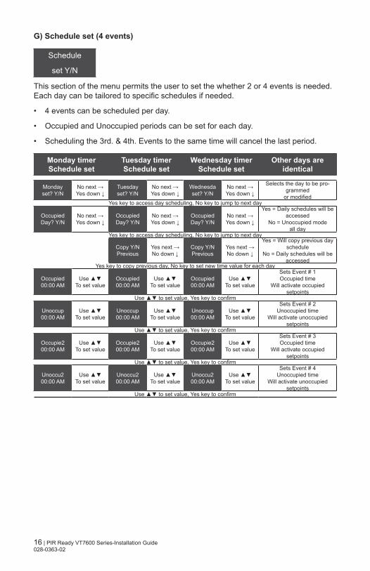
G) Schedule set (4 events)
Schedule
set Y/N
This section of the menu permits the user to set the whether 2 or 4 events is needed. Each day can be tailored to specific schedules if needed.
• 4 events can be scheduled per day.
• Occupied and Unoccupied periods can be set for each day.
• Scheduling the 3rd. & 4th. Events to the same time will cancel the last period.
Monday timer Schedule set
Tuesday timer Schedule set
Wednesday timer Schedule set
Other days are identical
Mondayset? Y/N
No next →Yes down ↓
Tuesdayset? Y/N
No next →Yes down ↓
Wednesdaset? Y/N
No next →Yes down ↓
Selects the day to be pro-grammed
or modifiedYes key to access day scheduling, No key to jump to next day
OccupiedDay? Y/N
No next →Yes down ↓
OccupiedDay? Y/N
No next →Yes down ↓
OccupiedDay? Y/N
No next →Yes down ↓
Yes = Daily schedules will be accessed
No = Unoccupied mode all day
Yes key to access day scheduling, No key to jump to next day
Copy Y/NPrevious
Yes next →No down ↓
Copy Y/NPrevious
Yes next →No down ↓
Yes = Will copy previous day schedule
No = Daily schedules will be accessed
Yes key to copy previous day, No key to set new time value for each day
Occupied00:00 AM
Use To set value
Occupied00:00 AM
Use To set value
Occupied00:00 AM
Use To set value
Sets Event # 1 Occupied time
Will activate occupied setpoints
Use to set value, Yes key to confirm
Unoccup00:00 AM
Use To set value
Unoccup00:00 AM
Use To set value
Unoccup00:00 AM
Use To set value
Sets Event # 2 Unoccupied time
Will activate unoccupied setpoints
Use to set value, Yes key to confirm
Occupie200:00 AM
Use To set value
Occupie200:00 AM
Use To set value
Occupie200:00 AM
Use To set value
Sets Event # 3 Occupied time
Will activate occupied setpoints
Use to set value, Yes key to confirm
Unoccu200:00 AM
Use To set value
Unoccu200:00 AM
Use To set value
Unoccu200:00 AM
Use To set value
Sets Event # 4 Unoccupied time
Will activate unoccupied setpoints
Use to set value, Yes key to confirm
17 | PIR Ready VT7600 Series-Installation Guide 028-0363-02
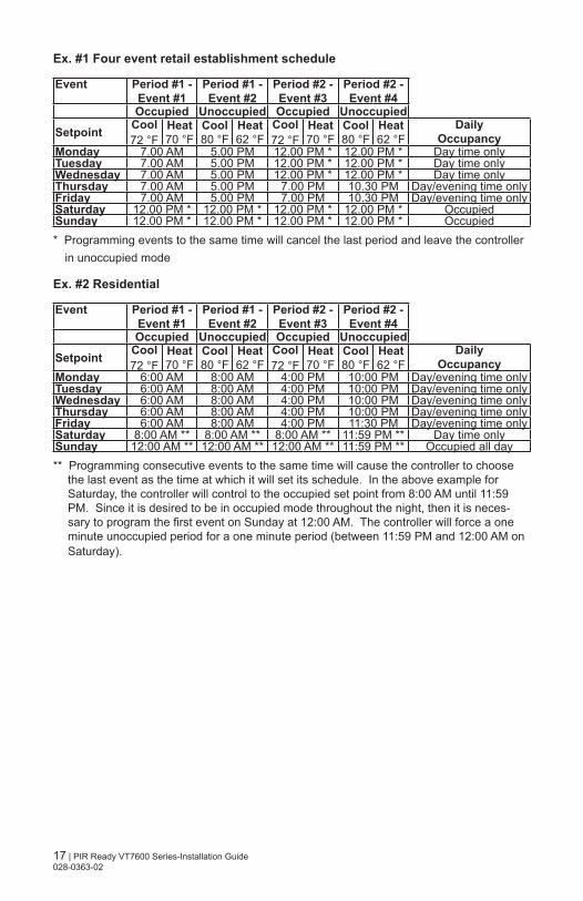
Ex. #1 Four event retail establishment schedule
Event Period #1 - Event #1
Period #1 - Event #2
Period #2 - Event #3
Period #2 - Event #4
Occupied Unoccupied Occupied Unoccupied
Setpoint Cool72 °F
Heat70 °F
Cool80 °F
Heat62 °F
Cool72 °F
Heat70 °F
Cool80 °F
Heat62 °F
DailyOccupancy
Monday 7.00 AM 5.00 PM 12.00 PM * 12.00 PM * Day time onlyTuesday 7.00 AM 5.00 PM 12.00 PM * 12.00 PM * Day time onlyWednesday 7.00 AM 5.00 PM 12.00 PM * 12.00 PM * Day time onlyThursday 7.00 AM 5.00 PM 7.00 PM 10.30 PM Day/evening time onlyFriday 7.00 AM 5.00 PM 7.00 PM 10.30 PM Day/evening time onlySaturday 12.00 PM * 12.00 PM * 12.00 PM * 12.00 PM * OccupiedSunday 12.00 PM * 12.00 PM * 12.00 PM * 12.00 PM * Occupied* Programming events to the same time will cancel the last period and leave the controller
in unoccupied mode
Ex. #2 Residential Event Period #1 -
Event #1Period #1 - Event #2
Period #2 - Event #3
Period #2 - Event #4
Occupied Unoccupied Occupied Unoccupied
Setpoint Cool72 °F
Heat70 °F
Cool80 °F
Heat62 °F
Cool72 °F
Heat70 °F
Cool80 °F
Heat62 °F
DailyOccupancy
Monday 6:00 AM 8:00 AM 4:00 PM 10:00 PM Day/evening time onlyTuesday 6:00 AM 8:00 AM 4:00 PM 10:00 PM Day/evening time onlyWednesday 6:00 AM 8:00 AM 4:00 PM 10:00 PM Day/evening time onlyThursday 6:00 AM 8:00 AM 4:00 PM 10:00 PM Day/evening time onlyFriday 6:00 AM 8:00 AM 4:00 PM 11:30 PM Day/evening time onlySaturday 8:00 AM ** 8:00 AM ** 8:00 AM ** 11:59 PM ** Day time onlySunday 12:00 AM ** 12:00 AM ** 12:00 AM ** 11:59 PM ** Occupied all day** Programming consecutive events to the same time will cause the controller to choose
the last event as the time at which it will set its schedule. In the above example for Saturday, the controller will control to the occupied set point from 8:00 AM until 11:59 PM. Since it is desired to be in occupied mode throughout the night, then it is neces-sary to program the first event on Sunday at 12:00 AM. The controller will force a one minute unoccupied period for a one minute period (between 11:59 PM and 12:00 AM on Saturday).
18 | PIR Ready VT7600 Series-Installation Guide 028-0363-02
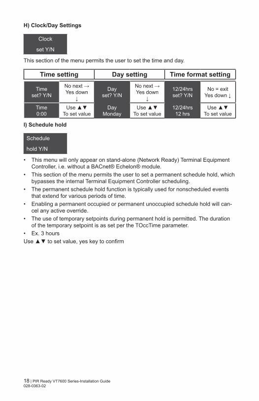
H) Clock/Day Settings
Clock
set Y/N
This section of the menu permits the user to set the time and day.
Time setting Day setting Time format setting
Timeset? Y/N
No next →Yes down
↓
Dayset? Y/N
No next →Yes down
↓
12/24hrsset? Y/N
No = exitYes down ↓
Time0:00
Use To set value
DayMonday
Use To set value
12/24hrs12 hrs
Use To set value
I) Schedule hold
Schedule
hold Y/N
• This menu will only appear on stand-alone (Network Ready) Terminal Equipment Controller, i.e. without a BACnet® Echelon® module.
• This section of the menu permits the user to set a permanent schedule hold, which bypasses the internal Terminal Equipment Controller scheduling.
• The permanent schedule hold function is typically used for nonscheduled events that extend for various periods of time.
• Enabling a permanent occupied or permanent unoccupied schedule hold will can-cel any active override.
• The use of temporary setpoints during permanent hold is permitted. The duration of the temporary setpoint is as set per the TOccTime parameter.
• Ex. 3 hoursUse to set value, yes key to confirm
19 | PIR Ready VT7600 Series-Installation Guide 028-0363-02
CONFIGURATION PARAMETERS
DEFAULT VALUESIGNIFICANCE AND ADJUSTMENTS
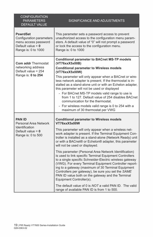
PswrdSetConfiguration parameters menu access passwordDefault value = 0Range is: 0 to 1000
This parameter sets a password access to prevent unauthorized access to the configuration menu param-eters. A default value of “0” will not prompt a password or lock the access to the configuration menu.Range is: 0 to 1000
Com addr Thermostat networking addressDefault value = 254 Range is: 0 to 254
Conditional parameter to BACnet MS-TP models (VT76xxX5x00B)Conditional parameter to Wireless models (VT76xxX5x00W)This parameter will only appear when a BACnet or wire-less network adapter is present. If the thermostat is in-stalled as a stand-alone unit or with an Echelon adapter, this parameter will not be used or displayed
- For BACnet MS-TP models valid range to use is from 1 to 127. Default value of 254 disables BACnet communication for the thermostat.
- For wireless models valid range is 0 to 254 with a maximum of 30 thermostat per VWG
PAN IDPersonal Area Network IdentificationDefault value = 0Range is: 0 to 500
Conditional parameter to Wireless models VT76xxX5x00W
This parameter will only appear when a wireless net-work adapter is present. If the Terminal Equipment Con-troller is installed as a stand-alone (Network Ready) unit or with a BACnet® or Echelon® adapter, this parameter will not be used or displayed.
This parameter (Personal Area Network Identification) is used to link specific Terminal Equipment Controllers to a single specific Schneider-Electric wireless gateway (VWG). For every Terminal Equipment Controller report-ing to a gateway (maximum of 30 Terminal Equipment Controllers per gateway), be sure you set the SAME PAN ID value both on the gateway and the Terminal Equipment Controller(s).
The default value of 0 is NOT a valid PAN ID. The valid range of available PAN ID is from 1 to 500.
20 | PIR Ready VT7600 Series-Installation Guide 028-0363-02
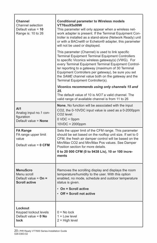
ChannelChannel selectionDefault value = 10Range is: 10 to 26
Conditional parameter to Wireless models VT76xxX5x00WThis parameter will only appear when a wireless net-work adapter is present. If the Terminal Equipment Con-troller is installed as a stand-alone (Network Ready) unit or with a BACnet® or Echelon® adapter, this parameter will not be used or displayed.
This parameter (Channel) is used to link specific Terminal Equipment Terminal Equipment Controllers to specific Viconics wireless gateway(s) (VWG). For every Terminal Equipment Terminal Equipment Control-ler reporting to a gateway (maximum of 30 Terminal Equipment Controllers per gateway), be sure you set the SAME channel value both on the gateway and the Terminal Equipment Controller(s).
Viconics recommends using only channels 15 and 25.The default value of 10 is NOT a valid channel. The valid range of available channel is from 11 to 26
AI1Analog input no.1 con-figurationDefault value = None
None, No function will be associated with the inputCO2, the 0-10VDC input value is used as a 0-2000ppm CO2 level:0 VDC = 0ppm10VDC = 2000ppm
FA RangeFA range upper limit value
Default value = 0 CFM
Sets the upper limit of the CFM range. This parameter should be set based on the rooftop unit size. If set to 0 CFM, the fresh air damper control will be based on the Min/Max CO2 and Min/Max Pos values. See Damper Position section for more details.0 to 20 000 CFM (0 to 9438 L/s), 10 or 100 incre-ments
MenuScro Menu scrollDefault value = On = Scroll active
Removes the scrolling display and displays the room temperature/humidity to the user. With this option enabled, no mode, schedule and outdoor temperature status is given.
On = Scroll active Off = Scroll not active
LockoutKeypad lockout levelsDefault value = 0 No lock
0 = No lock1 = Low level2 = High level
21 | PIR Ready VT7600 Series-Installation Guide 028-0363-02
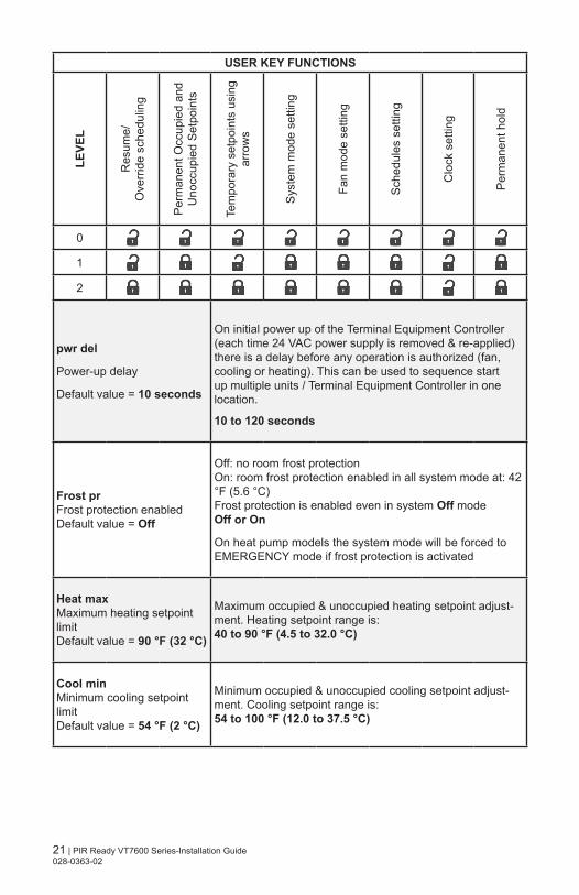
USER KEY FUNCTIONSLE
VEL
Res
ume/
Ove
rrid
e sc
hedu
ling
Per
man
ent O
ccup
ied
and
Uno
ccup
ied
Set
poin
ts
Tem
pora
ry s
etpo
ints
usi
ngar
row
s
Sys
tem
mod
e se
tting
Fan
mod
e se
tting
Sch
edul
es s
ettin
g
Clo
ck s
ettin
g
Per
man
ent h
old
0
1
2
pwr del
Power-up delay
Default value = 10 seconds
On initial power up of the Terminal Equipment Controller (each time 24 VAC power supply is removed & re-applied) there is a delay before any operation is authorized (fan, cooling or heating). This can be used to sequence start up multiple units / Terminal Equipment Controller in one location.
10 to 120 seconds
Frost prFrost protection enabledDefault value = Off
Off: no room frost protectionOn: room frost protection enabled in all system mode at: 42 °F (5.6 °C) Frost protection is enabled even in system Off modeOff or On
On heat pump models the system mode will be forced to EMERGENCY mode if frost protection is activated
Heat maxMaximum heating setpoint limitDefault value = 90 °F (32 °C)
Maximum occupied & unoccupied heating setpoint adjust-ment. Heating setpoint range is: 40 to 90 °F (4.5 to 32.0 °C)
Cool minMinimum cooling setpoint limitDefault value = 54 °F (2 °C)
Minimum occupied & unoccupied cooling setpoint adjust-ment. Cooling setpoint range is: 54 to 100 °F (12.0 to 37.5 °C)
22 | PIR Ready VT7600 Series-Installation Guide 028-0363-02
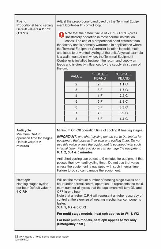
PbandProportional band settingDefault value 2 = 2.0 °F (1.1 °C)
Adjust the proportional band used by the Terminal Equip-ment Controller PI control loop.
Note that the default value of 2.0 °F (1.1 °C) gives satisfactory operation in most normal installation cases. The use of a proportional band different than
the factory one is normally warranted in applications where the Terminal Equipment Controller location is problematic and leads to unwanted cycling of the unit. A typical example is a wall mounted unit where the Terminal Equipment Controller is installed between the return and supply air feeds and is directly influenced by the supply air stream of the unit.
VALUE °F SCALE PBAND
°C SCALE PBAND
2 2 F 1.1 C3 3 F 1.7 C4 4 F 2.2 C5 5 F 2.8 C6 6 F 3.3 C7 7 F 3.9 C8 8 F 4.4 C
AnticycleMinimum On-Off operation time for stagesDefault value = 2 minutes
Minimum On-Off operation time of cooling & heating stages.
IMPORTANT, anti-short cycling can be set to 0 minutes for equipment that posses their own anti cycling timer. Do not use this value unless the equipment is equipped with such internal timer. Failure to do so can damage the equipment.0, 1, 2, 3, 4 & 5 minutes
Anti-short cycling can be set to 0 minutes for equipment that posses their own anti cycling timer. Do not use that value unless the equipment is equipped with such internal timer. Failure to do so can damage the equipment.
Heat cph Heating stages cycles per hour Default value = 4 C.P.H.
Will set the maximum number of heating stage cycles per hour under normal control operation. It represents the maxi-mum number of cycles that the equipment will turn ON and OFF in one hour. Note that a higher C.P.H will represent a higher accuracy of control at the expense of wearing mechanical components faster. 3, 4, 5, 6,7 & 8 C.P.H.
For multi stage models, heat cph applies to W1 & W2
For heat pump models, heat cph applies to W1 only (Emergency heat )

23 | PIR Ready VT7600 Series-Installation Guide 028-0363-02
Cool cph Cooling stages cycles per hour Default value = 4 C.P.H.
Will set the maximum number of cooling stage cycles per hour under normal control operation. It represents the maximum number of cycles that the equipment will turned on and off in one hour. Note that a higher C.P.H will represent a higher accuracy of control at the expense of wearing mechanical compo-nents faster. 3 or 4 C.P.H.
For multi stage models, cool cph applies to Y1 & Y2
For heat pump models, cool cph applies to Y1 & Y2 in cooling and heating independently of the reversing valve position
DeadbandMinimum deadbandDefault value = 2.0 °F (1.1 °C)
The minimum deadband value between the heating and cooling setpoints. When modified, it will take effect only when any of the setpoints are modified again.
Range is: 2, 3, or 4 °F, 1.0 °F increments (1.0 to 2.0 °C, 0.5 °C increments)
Fan contFan controlDefault value = On
Fan control in heating mode.When selecting On; the Terminal Equipment Controller in all cases will always control the fan (terminal G).Valid for On or Auto fan modeWhen selecting Off; the fan (terminal G), when heating stages (terminals W1 & W2) are solicited, will not be energized. The fan in this case will be controlled by the equipment fan limit control.Valid only for Auto fan mode. On fan mode will leave the fan always on.ON OR OFFFor multi stage models, fan control applies to W1 & W2For heat pump models, fan control applies to W1 only (Emergency heat)
Fan delFan delayDefault value = Off
Fan delay extends fan operation by 60 seconds after the call for heating or cooling ends.Valid only for Auto fan mode. “On” fan mode will leave the fan always on.Off or On
TOccTimeTemporary occupancy timeDefault value = 2 hours
Temporary occupancy time with occupied mode setpoints when override function is enabled.When the Terminal Equipment Controller is in unoccu-pied mode, function is enabled with either the menu or UI2 configured as remote override input.
Range is: 0,1, 2, 3, 4, 5, 6, 7, 8, 9, 10, & up to 24 hoursCal RS Room temperature sensor calibrationDefault value = 0.0 °F or °C
Offset that can be added/subtracted to the actual dis-played room temperature
± 5.0 °F, (± 2.5 °C)

24 | PIR Ready VT7600 Series-Installation Guide 028-0363-02
Cal OS Outside air temperature sensorcalibrationDefault value = 0.0 °F or °C
Offset that can be added/subtracted to the actual dis-played outdoor temperature.
± 5.0 °F, (± 2.5 °C)
H stageNumber of heating stages.Applicable to 2 stage models onlyDefault value = 2 stages
Will revert the operation of 2 stages Terminal Equip-ment Controller to single stage operation only when the second heating step is not needed.1 or 2 stages
For heat pump models, H stage is limited to 1 stageonly (W1 – Aux. Heat)
C stage
Number of cooling stages Default value = 2 stages
Will revert the operation of 2 stage Terminal Equipment Controller to single stage operation only when the sec-ond cooling step is not needed.1 or 2 stages
H lock
Outside air temperature heating lockout
Default value = 120 °F (49 °C)
Disables heating stage operation based on outdoor air temperature.Function will only be enabled if OS (outside air tempera-ture sensor) is connected. From -15 °F up to 120 °F (-26 °C up to 49 °C)
C lock
Outside air temperature mechanical cooling lockout.
Default value = -40 °F (-40 °C)
Disables cooling stage operation based on outdoor air temperature.On economizer model, free cooling will not be disabled by this function.Function will only be enabled if OS (outside air tempera-ture sensor) is connected.From -40 °F up to 95 °F ( -40 °C up to 35 °C )
Unocc TM
Unoccupied Timer value
Default 0.5 hours
Time delay between the moment where the Terminal Equipment Controller toggles from occupied to unoccu-pied after the last movement has been detected by the PIR.
Range is: 0.5 to 24.0 hours in 0.5 hour increments
25 | PIR Ready VT7600 Series-Installation Guide 028-0363-02
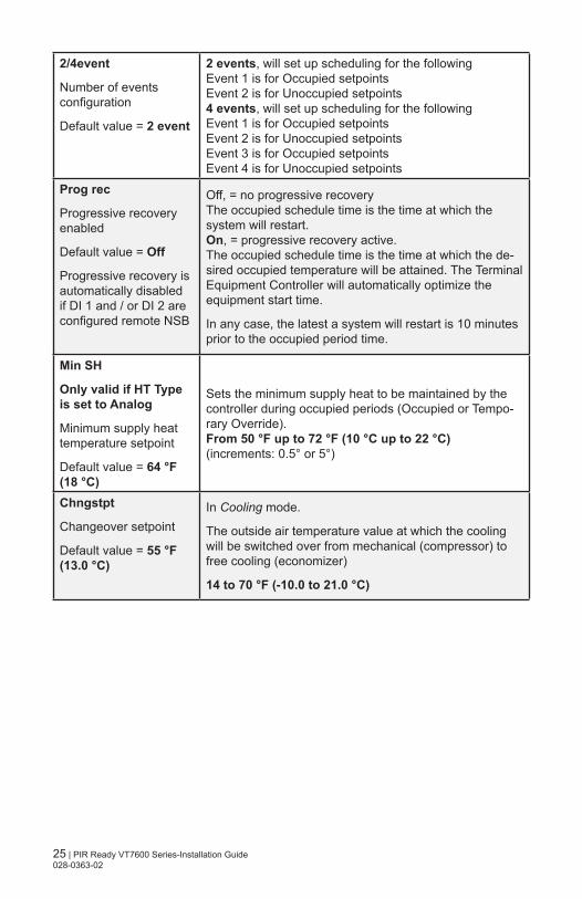
2/4event
Number of events configuration
Default value = 2 event
2 events, will set up scheduling for the followingEvent 1 is for Occupied setpointsEvent 2 is for Unoccupied setpoints4 events, will set up scheduling for the followingEvent 1 is for Occupied setpointsEvent 2 is for Unoccupied setpointsEvent 3 is for Occupied setpointsEvent 4 is for Unoccupied setpoints
Prog rec
Progressive recovery enabled
Default value = Off
Progressive recovery is automatically disabled if DI 1 and / or DI 2 are configured remote NSB
Off, = no progressive recoveryThe occupied schedule time is the time at which the system will restart.On, = progressive recovery active.The occupied schedule time is the time at which the de-sired occupied temperature will be attained. The Terminal Equipment Controller will automatically optimize the equipment start time.
In any case, the latest a system will restart is 10 minutes prior to the occupied period time.
Min SH
Only valid if HT Type is set to Analog
Minimum supply heat temperature setpoint
Default value = 64 °F (18 °C)
Sets the minimum supply heat to be maintained by the controller during occupied periods (Occupied or Tempo-rary Override). From 50 °F up to 72 °F (10 °C up to 22 °C)(increments: 0.5° or 5°)
Chngstpt
Changeover setpoint
Default value = 55 °F (13.0 °C)
In Cooling mode.
The outside air temperature value at which the cooling will be switched over from mechanical (compressor) to free cooling (economizer)
14 to 70 °F (-10.0 to 21.0 °C)
26 | PIR Ready VT7600 Series-Installation Guide 028-0363-02
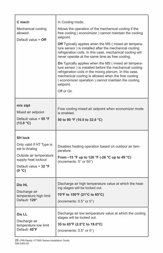
C mech
Mechanical cooling allowed
Default value = Off
In Cooling mode.
Allows the operation of the mechanical cooling if the free cooling ( economizer ) cannot maintain the cooling setpoint.
Off Typically applies when the MS ( mixed air tempera-ture sensor ) is installed after the mechanical cooling refrigeration coils. In this case, mechanical cooling will never operate at the same time as free cooling.
On Typically applies when the MS ( mixed air tempera-ture sensor ) is installed before the mechanical cooling refrigeration coils in the mixing plenum. In this case, mechanical cooling is allowed when the free cooling ( economizer operation ) cannot maintain the cooling setpoint.
Off or On
mix stpt
Mixed air setpoint
Default value = 55 °F (13.0 °C)
Free cooling mixed air setpoint when economizer mode is enabled.
50 to 90 °F (10.0 to 32.0 °C)
SH lock
Only valid if HT Type is set to Analog
Outside air temperature supply heat lockout
Default value = 32 °F (0 °C)
Disables heating operation based on outdoor air tem-perature.
From –15 °F up to 120 °F (-26 °C up to 49 °C)(increments: 5° or 50°)
Dis HL
Discharge air temperature high limitDefault: 120°
Discharge air high temperature value at which the heat-ing stages will be locked out.
70°F to 150°F (21°C to 65°C)
(increments: 0.5° or 5°)
Dis LL
Discharge air temperature low limitDefault: 45°F
Discharge air low temperature value at which the cooling stages will be locked out.
35 to 65°F (2.0°C to 19.0°C)
(increments: 0.5° or 5°)
27 | PIR Ready VT7600 Series-Installation Guide 028-0363-02
Min Pos
Minimum Fresh Air Damper/Economizer Position
Default value = 0%
Minimum fresh air damper position. Effective only in Occupied mode (Fan is ON). This value is also used to determine the fresh air damper position based on the Min/Max CO2 and Min/Max Pos values set. See Fresh Air Damper Position section for more details.
0% to 100%, 1 or 10 increments
Max Pos
Maximum Fresh Air Damper/Economizer Position
Default value = 100%
Maximum fresh air damper position. Effective only in Oc-cupied mode (Fan is ON). This value is used to deter-mine the fresh air damper position based on the Min/Max CO2 and Min/Max Pos values set. See Fresh Air Damper Position section for more details.
0% to 100%, 1 or 10 increments
Min FAMinimum Fresh Air ValueDefault value = 0 CFM
Minimum fresh air required. Effective only in Occupied mode (Fan is ON). This value is used to determine the fresh air damper position based on the Min/Max CO2 and Min/Max FA values (if FA Range is set to other than 0 CFM). See Fresh Air Damper Position section for more details.0 to 20 000 CFM (0 to 9438 L/s) (the value set cannot exceed the value of FA Range parameter), 10 or 100 increments
Max FAMaximum Fresh Air ValueDefault value = 0 CFM
Maximum fresh air allowed. Effective only in Occupied mode (Fan is ON). This value is used to determine the fresh air damper position based on the Min/Max CO2 and Min/Max FA values set (if FA Range is set to other than 0 CFM). See Fresh Air Damper Position section for more details. 0 to 20 000 CFM (0 to 9438 L/s) (the value set cannot exceed the value of FA Range parameter), 10 or 100 increments
Min CO2Minimum CO2 LevelDefault value = 800 ppm
Minimum CO2 Level required. Effective only in Occupied mode (Fan is ON). This value is used to determine the fresh air damper position based on the Min/Max CO2 and Min/Max Pos values set. See Fresh Air Damper Position section for more details.0 to 2000 ppm, 10 or 100 increments
28 | PIR Ready VT7600 Series-Installation Guide 028-0363-02
Max CO2Maximum CO2 LevelDefault value = 1200 ppm
Maximum CO2 Level allowed. Effective only in Occupied mode (Fan is ON). This value is used to determine the fresh air damper position based on the Min/Max CO2 and Min/Max Pos values set. See Fresh Air Damper Position section for more details.
0 to 2000 ppm, 10 or 100 increments
MS disDisplay mixed air tem-perature, only if sensor is installed.
Used as diagnostic / service help to troubleshoot and diag-nose economizer operation.
CO2 Level
Display CO2 Level, only if a CO2 transmitter is installed at AI1 input.
Used as diagnostic / service help to troubleshoot and diag-nose IAQ control operation
29 | PIR Ready VT7600 Series-Installation Guide 028-0363-02
fresh air daMper ConTrol sequenCes
The fresh air damper can be controlled through more than one sequence to achieve different control strategies such as free cooling (economizer mode), minimum fresh air control and CO2 level control. Here are the control sequences available:
Note: For the sequences mentioned below, the following conditions must be met in order for the sequences to be performed as stated:
- Max Pos parameter value must be greater than Min Pos Parameter value. - Mac CO2 parameter value must be greater than Min CO2 Parameter value. - Max FA parameter value must be greater than Min FA Parameter value.
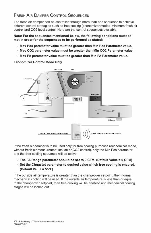
Economizer Control Mode Only
If the fresh air damper is to be used only for free cooling purposes (economizer mode, without fresh air measurement station or CO2 control), only the Min Pos parameter and the free cooling sequence will be active.
- The FA Range parameter should be set to 0 CFM. (Default Value = 0 CFM) - Set the Chngstpt parameter to desired value which free cooling is enabled.
(Default Value = 55°F)
If the outside air temperature is greater than the changeover setpoint, then normal mechanical cooling will be used. If the outside air temperature is less than or equal to the changeover setpoint, then free cooling will be enabled and mechanical cooling stages will be locked out.
30 | PIR Ready VT7600 Series-Installation Guide 028-0363-02
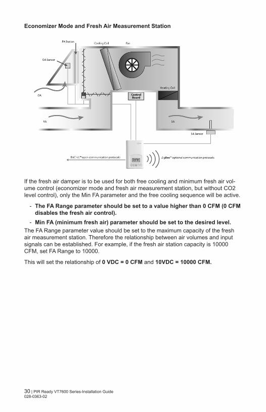
Economizer Mode and Fresh Air Measurement Station
If the fresh air damper is to be used for both free cooling and minimum fresh air vol-ume control (economizer mode and fresh air measurement station, but without CO2 level control), only the Min FA parameter and the free cooling sequence will be active.
- The FA Range parameter should be set to a value higher than 0 CFM (0 CFM disables the fresh air control).
- Min FA (minimum fresh air) parameter should be set to the desired level.The FA Range parameter value should be set to the maximum capacity of the fresh air measurement station. Therefore the relationship between air volumes and input signals can be established. For example, if the fresh air station capacity is 10000 CFM, set FA Range to 10000.
This will set the relationship of 0 VDC = 0 CFM and 10VDC = 10000 CFM.
31 | PIR Ready VT7600 Series-Installation Guide 028-0363-02
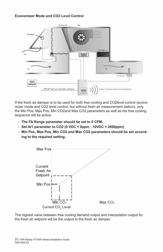
Economizer Mode and CO2 Level Control
If the fresh air damper is to be used for both free cooling and CO2level control (econo-mizer mode and CO2 level control, but without fresh air measurement station), only the Min Pos, Max Pos, Min CO2and Max CO2 parameters as well as the free cooling sequence will be active.
- The FA Range parameter should be set to 0 CFM. - Set AI1 parameter to CO2 (0 VDC = 0ppm ; 10VDC = 2000ppm) - Min Pos, Max Pos, Min CO2 and Max CO2 parameters should be set accord-
ing to the required setting.
The highest value between free cooling demand output and interpolation output for the fresh air setpoint will be the output to the fresh air damper.
Current CO2 Level

32 | PIR Ready VT7600 Series-Installation Guide 028-0363-02
Economizer Mode, CO2 Level Control and Fresh Air Measurement Station
If the fresh air damper is to be used for both free cooling and CO2 level control with a fresh air measurement station, only the Min FA, Max FA, Min CO2 and Max CO2 parameters as well as the free cooling sequence will be active.
- The FA Range parameter should be set to something other than 0 CFM. - Use an air flow transmitter to read fresh air level with AI2 input (0-5 VDC
input) - Min FA, Max FA, Min CO2 and Max CO2 parameters should be set according
to the required setting.
The highest value between free cooling demand output and interpolation output for the fresh air setpoint based on the CO2 level will be the output to the fresh air damper.
Current CO2 Level
33 | PIR Ready VT7600 Series-Installation Guide 028-0363-02
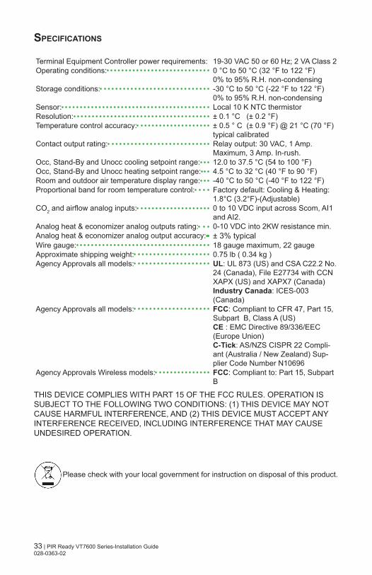
specIfIcatIons
Terminal Equipment Controller power requirements: 19-30 VAC 50 or 60 Hz; 2 VA Class 2Operating conditions: 0 °C to 50 °C (32 °F to 122 °F)
0% to 95% R.H. non-condensingStorage conditions: -30 °C to 50 °C (-22 °F to 122 °F)
0% to 95% R.H. non-condensingSensor: Local 10 K NTC thermistorResolution: ± 0.1 °C (± 0.2 °F)Temperature control accuracy: ± 0.5 ° C (± 0.9 °F) @ 21 °C (70 °F)
typical calibratedContact output rating: Relay output: 30 VAC, 1 Amp.
Maximum, 3 Amp. In-rush.Occ, Stand-By and Unocc cooling setpoint range: 12.0 to 37.5 °C (54 to 100 °F)Occ, Stand-By and Unocc heating setpoint range: 4.5 °C to 32 °C (40 °F to 90 °F)Room and outdoor air temperature display range: -40 °C to 50 °C (-40 °F to 122 °F)Proportional band for room temperature control: Factory default: Cooling & Heating:
1.8°C (3.2°F)-(Adjustable)CO2 and airflow analog inputs: 0 to 10 VDC input across Scom, AI1
and AI2.Analog heat & economizer analog outputs rating: 0-10 VDC into 2KW resistance min.Analog heat & economizer analog output accuracy: ± 3% typicalWire gauge: 18 gauge maximum, 22 gauge Approximate shipping weight: 0.75 lb ( 0.34 kg )Agency Approvals all models: UL: UL 873 (US) and CSA C22.2 No.
24 (Canada), File E27734 with CCN XAPX (US) and XAPX7 (Canada)Industry Canada: ICES-003 (Canada)
Agency Approvals all models: FCC: Compliant to CFR 47, Part 15, Subpart B, Class A (US)CE : EMC Directive 89/336/EEC (Europe Union)C-Tick: AS/NZS CISPR 22 Compli-ant (Australia / New Zealand) Sup-plier Code Number N10696
Agency Approvals Wireless models: FCC: Compliant to: Part 15, Subpart B
THIS DEVICE COMPLIES WITH PART 15 OF THE FCC RULES. OPERATION IS SUBJECT TO THE FOLLOWING TWO CONDITIONS: (1) THIS DEVICE MAY NOT CAUSE HARMFUL INTERFERENCE, AND (2) THIS DEVICE MUST ACCEPT ANY INTERFERENCE RECEIVED, INCLUDING INTERFERENCE THAT MAY CAUSE UNDESIRED OPERATION.
Please check with your local government for instruction on disposal of this product.
34 | PIR Ready VT7600 Series-Installation Guide 028-0363-02
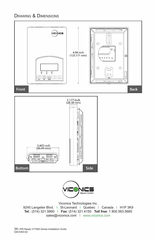
Drawing & DiMensions
Viconics Technologies Inc.9245 Langelier Blvd. I St-Leonard I Quebec I Canada I H1P 3K9Tel.: (514) 321.5660 I Fax: (514) 321.4150 Toll free: 1 800.563.5660
[email protected] I www.viconics.com