Embed Size (px)
Citation preview

Extreme. Precision. Positioning.
EXTR
EME
Motors for use in vacuum should not only withstand the vacuum (no bursting of air inclusions), they must not contaminate the vacuum either. By selecting suitable mate-rials and optimised conditioning processes phytron VSS/VSH stepper motors are ideally suited for use in a vacuum. Through many ye-ars of experience with special materials for use in Space, we have put a focus on mate-rials with minimal molecular outgassing and high heat resistance. This is the prerequisite for a high vacuum quality and genuine mea-surement results in scientific and medical applications.
For exact positioning in vacuum, stepper mo-tors are therefore particularly suitable be-cause they can precisely position even without
sensitive feedback providers. Thereforephytron VSS/VSH stepper motors can be used in particularly challenging environmental con-ditions (radiation, cryo-temperatures and in a modified design even in Space).
Since stepper motors do not generate jitter effects while holding a position, this technology is ideal for precisely aligning optical instruments, mirrors, antennas or samples e.g. in high-resolution microscopes, particle accelerators or molecular analysis devices.
The VSS/VSH series is completely manufac-tured in Germany. You have special require-ments? We are pleased to develope a tailored design for your application.
VSS / VSH Stepper MotorFor Applications up to Ultra-high-vacuum
• 2-phase stepper motors• Holding torques from 3.4 mNm to 13 Nm• Diameters from 19 to 125 mm• Number of steps 200 (standard)• Step accuracy 5% for 1.8° • Operating voltage (power stage)
Size 19 to 57: 70 VDCSize 80 to 126: 120 VDC
• Outgassing holes to avoid pockets oftrapped gas
Options• VGPL precision planetary gear or
Harmonic Drive gear • Thermocouple type KTC/ Pt100 resis-
tor sensor• Resolver• Double shaft
Customised solutions• Operating in an agressive environment• Clean room applications to clean room
class ISO 5 (acc. to ISO 14644-1)• Motors with spindle
In Focus
High Temperature Radiation ResistanceVacuum
Highlights
Performance & Lifetimephytron in-Vacuum motors are based on a technology that can also be found in the most challenging projects of our time. From a variety of sa-tellites up to the Mars rover Curiosity: phytron motors drive applications in distant worlds - highly accurate, reliable and durable. Driven within their specification range, high quality components and a proven design make sure: These motors don’t let you down!
Cleanliness phytron motors for use in ultra high vacuum (UHV) contain only mate-rials that also meet the requirements of the ECSS (European Space re-gulations). Thus, each material has a maximum TML (Total Mass Loss) value < 1% and a maximum CVCM (Volatile Mass Losses) value < 0.1 %. You will receive your UHV motor, double-wrapped and vacuum sealed.
RoHScomplient
Edition 2017 April
www.phytron.eu/vss-vshENG
Extreme
VSS / VSH – data sheet
High Temperature
Radiation Resistance
Vacuum
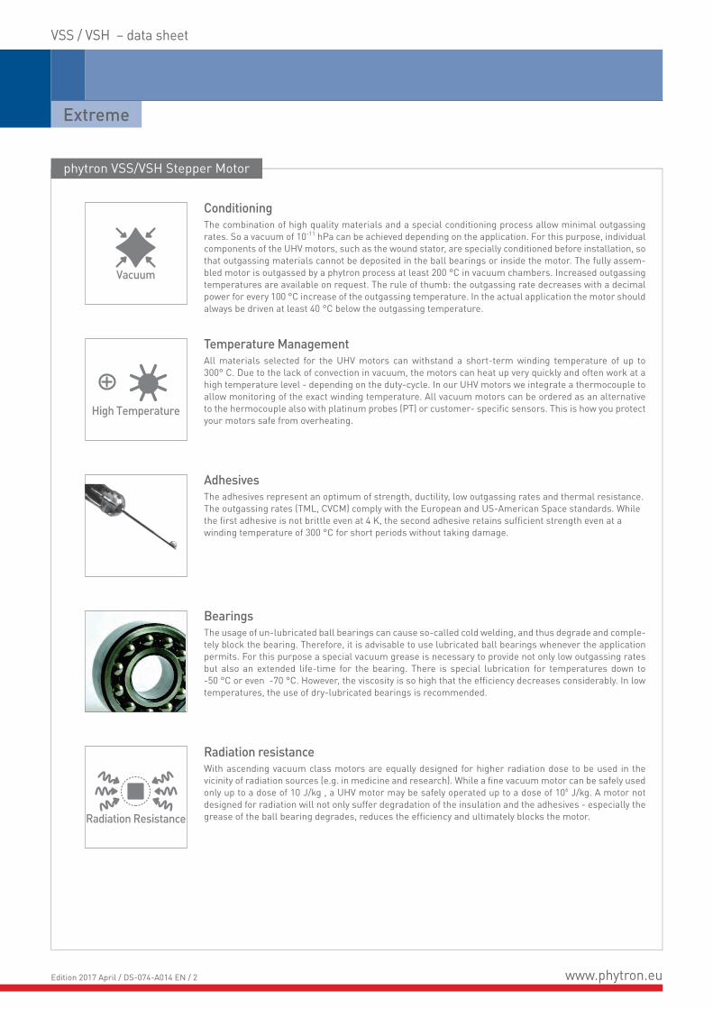
Radiation resistanceWith ascending vacuum class motors are equally designed for higher radiation dose to be used in thevicinity of radiation sources (e.g. in medicine and research). While a fine vacuum motor can be safely used only up to a dose of 10 J/kg , a UHV motor may be safely operated up to a dose of 106 J/kg. A motor not designed for radiation will not only suffer degradation of the insulation and the adhesives - especially the grease of the ball bearing degrades, reduces the efficiency and ultimately blocks the motor.
BearingsThe usage of un-lubricated ball bearings can cause so-called cold welding, and thus degrade and comple-tely block the bearing. Therefore, it is advisable to use lubricated ball bearings whenever the application permits. For this purpose a special vacuum grease is necessary to provide not only low outgassing rates but also an extended life-time for the bearing. There is special lubrication for temperatures down to -50 °C or even -70 °C. However, the viscosity is so high that the efficiency decreases considerably. In low temperatures, the use of dry-lubricated bearings is recommended.
AdhesivesThe adhesives represent an optimum of strength, ductility, low outgassing rates and thermal resistance. The outgassing rates (TML, CVCM) comply with the European and US-American Space standards. While the first adhesive is not brittle even at 4 K, the second adhesive retains sufficient strength even at a winding temperature of 300 °C for short periods without taking damage.
Temperature ManagementAll materials selected for the UHV motors can withstand a short-term winding temperature of up to 300° C. Due to the lack of convection in vacuum, the motors can heat up very quickly and often work at a high temperature level - depending on the duty-cycle. In our UHV motors we integrate a thermocouple to allow monitoring of the exact winding temperature. All vacuum motors can be ordered as an alternative to the hermocouple also with platinum probes (PT) or customer- specific sensors. This is how you protect your motors safe from overheating.
ConditioningThe combination of high quality materials and a special conditioning process allow minimal outgassing rates. So a vacuum of 10-11 hPa can be achieved depending on the application. For this purpose, individual components of the UHV motors, such as the wound stator, are specially conditioned before installation, so that outgassing materials cannot be deposited in the ball bearings or inside the motor. The fully assem-bled motor is outgassed by a phytron process at least 200 °C in vacuum chambers. Increased outgassing temperatures are available on request. The rule of thumb: the outgassing rate decreases with a decimal power for every 100 °C increase of the outgassing temperature. In the actual application the motor should always be driven at least 40 °C below the outgassing temperature.
phytron VSS/VSH Stepper Motor
www.phytron.euEdition 2017 April / DS-074-A014 EN / 2
VSS / VSH data sheet
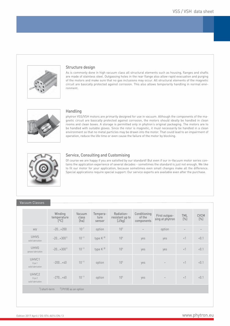
Structure designAs is commonly done in high vacuum class all structural elements such as housing, flanges and shafts are made of stainless steel. Outgassing holes in the rear flange also allow rapid evacuation and purging of the motors and make sure that no gas inclusions may occur. All structural elements of the magnetic circuit are basically protected against corrosion. This also allows temporarily handling in normal envi-ronment.
Handlingphytron VSS/VSH motors are primarily designed for use in vacuum. Although the components of the ma-gnetic circuit are basically protected against corrosion, the motors should ideally be handled in clean rooms and clean boxes. A storage is permitted only in phytron‘s original packaging. The motors are to be handled with suitable gloves. Since the rotor is magnetic, it must necessarily be handled in a clean environment so that no metal particles may be drawn into the motor. That could lead to an impairment of operation, reduce the life time or even cause the failure of the motor by blocking.
Service, Consulting and CustomisingOf course we are happy if you are satisfied by our standard! But even if our in-Vacuum motor series con-tains the application experience of several decades - sometimes the standard is just not enough. We like to fit our motor for your application, because sometimes even small changes make all the difference. Special applications require special support: Our service experts are available even after the purchase.
Windingtemperature
[°C]
Vacuumclass[ha]
Tempera-ture
sensor
Radiation-resistant up to
[J/kg]
Conditioning of the
componentsFirst outgas-
sing at phytronTML [%]
CVCM [%]
HV -20...+200 10-7 option 102 – option – –
UHVSsolid lubrication
-20...+3001) 10-11 type K 2) 106 yes yes <1 <0.1
UHVGgrease lubrication
-20...+3001) 10-11 type K 2) 106 yes yes <1 <0.1
UHVC1Cryo 1
solid lubrication-200...+40 10-11 option 106 yes – <1 <0.1
UHVC2Cryo 2
solid lubrication-270...+40 10-11 option 106 yes – <1 <0.1
1) short-term 2) Pt100 as an option
Vacuum Classes
www.phytron.euEdition 2017 April / DS-074-A014 EN / 3

Extreme
VSS / VSH – data sheet
{{{{{
Res
olut
ion
Current > 0.5*IN is only needed for a short time?
Use motor
no
no
no
no
Use biggermotor size Select motor sizewith gear
Dyn
amic
s
yes
yes
yes
yes
yes
Size
/ Ty
peD
uty
Cyc
le
yes
Motor (if necessary gear selection) is suitable
START
nono
Preliminary assessment based on the required torqueat max. speed (motor characteristics) and the availableinstallation space.(Note: available voltage limits the max. speed)
Is a full step resolution of 1.8° (200 step motor) enough?(The resolution can be increased by electronic control systemslike micro step mode.)
Torque at the operating point (max. speed, max. load)at 0.5*IN current (current is proportional to torque)?(Background: overheating of the motor windings)
For direct-drive (gearless motor):If external mass inertia <50x to <200x inertia of the rotor? (here you must accelerate with very long ramps in the micro step mode.)
For direct-drive (gearless motor):High dynamics/acceleration required?:If external mass inertia <1x to <10x inertia of the rotor?
For direct-drive and for motor gear units:Max. motor speed < 400 rev./min?for dry lubrication < 100 rev./min?(background: rotor heating)
Configuration guide
Derating - Duty-Cycle-Design for Applications in Vacuum
Motors driving in a vacuum heat up very quickly depending on their duty cycle. Driven with nomal current the maximum temperature will be reached within several minutes. Therefore it is necessary to monitor the motor‘s temperature (K-element) or to design a duty cycle with enough off-time to always keep the motor on a safe temperature level.
The shown curve is set at an environmental temperature of 20 °C. To give you an idea of how the chosen current influences the motor temperature we drew two curves of a VSS 57 motor. Driven with 400 rpm at 0.5 of the nominal current, the motor takes longer to heat up due to less ohmic losses then driven with the full nominal current.
The third curve (VSS 32) with 0.5 nominal current and 200 rmp only leads to a steady state temperature within the safe temperature limits. A higher rotational speed increases the magnetic losses. Therefore high speeds should be avoided as far as possible to reduce heat losses and to protect the bearings.
0
2010 30 40 8060 7050
40
20
60
80
100
120
140
160
180
200
0
°C
min
winding temperature (in vacuum), environment 20 °C
1/2 nominal current, 48 V, 400 rpm 1/2 nominal current, 48 V, 200 rpmcooling down1/1 nominal current, 48 V, 400 rpm cooling down
short time operation only (HV motor)
after 300 min. steady-state temperaturecontinuous operation possibleVSS 32
VSS 57VSS 57
www.phytron.euEdition 2017 April / DS-074-A014 EN / 4

VSS / VSH – data sheet
Lg6
ØG1
IJ
HØA
ØG2
ØG1
F1
4)
4)
4)
D E
B1 F2
Option: radial
VSS/VSH Standard 200-steps
4 lead parallel3)
Electrical Characteristics Mechanical Characteristics
Curr
ent/
Phas
e IN
Resis
tanc
e/Ph
ase
Indu
ctivi
ty/Ph
ase
max
. ope
ratin
g vo
ltage
AWG
Hold
ing
torq
ue 2)
Dete
nt to
rque
Roto
r ine
rtia Loads
Mas
s
Dimensions in mmaxial radial
A Ω mH VDC mNm mNm kg cm2 N N kg A B1 D E F1 F2 G14) G24) K L M N
19.200.0.61)
19.200.1.21)0.61.2
2.10.63
0.850.23
70
28 3.43.5 0.9 0.0009 3 3 0.05 19 26.5 1 2 7.5 6.5 2.5 2.5 19 10 16 M2.5
20.200.0.6 20.200.1.2
0.61.2
3.450.95
1.10.4 28 8 1 0.002 3 3 0.075 19 43 1 2 7.5 6.5 2.5 2.5 19 10 16 M2.5
25.200.0.6 25.200.1.21)
0.61.2
3.250.95
1.50.4
2826 12 2 0.0025 5 5 0.08 25 31 1 2.5 9.5 8.5 3 3 25 14 21.5 2.2
26.200.0.6 26.200.1.2
0.61.2
5.851.7
3.21.0
2826 28 1.9 0.006 5 5 0.13 25 47 1 2.5 9.5 8.5 3 3 25 14 21.5 2.2
32.200.0.6 32.200.1.21)
0.61.2
4.61.25
5.31.2 26 40 3 0.01 5 15 0.17 32 38.5 1 3 11 10 4 4 32 18 27 2.8
33.200.0.6 33.200.1.21)
0.61.2
7.51.9
9.32.2 26 68 3.3 0.018 5 15 0.26 32 57.5 1 3 11 10 4 4 32 18 27 2.8
42.200.1.21) 42.200.2.51)
1.22.5
1.70.34
30.7
2422 120 5 0.045 20 40 0.35 42 54 1 3 16 15 5 4 42 22 36 3.2
43.200.1.21) 43.200.2.5
1.22.5
2.60.5
5.21.2
2422 235 7 0.077 20 40 0.52 42 69 1 3 16 15 5 4 42 22 36 3.2
52.200.1.2 52.200.2.5
1.22.5
2.650.6
71.6
2422 350 13 0.15 25 70 0.72 52 65 1.5 3.5 17.5 16 6 4 52 28 44 4.3
56.200.1.2 56.200.2.5
1.22.5
3.90.8
9.52.4
2422 420 30 0.17 40 80 0.78 56.4 58.1 1.5 4.5 22 20.5 6.35 6.35 60 38.1 47.1 5.2
57.200.1.2 57.200.2.51)
1.22.5
3.90.8
11.62.9
2422 840 50 0.24 40 80 0.99 56.4 74.1 1.5 4.5 22 20.5 6.35 6.35 60 38.1 47.1 5.2
80.200.5 5 0.4 2.3
120
18 2300 120 1.24 50 180 2.8 80 100 2 7.5 27 25 10 9 80 50 68 6.4
100.200.10 10 0.15 2.1 16 4300 140 4.4 70 300 5 100 125.5 2 8 32 30 12 12 100 60 86 6.4
126.200.10 10 0.23 3.9 16 13000 290 18.2 150 700 13.9 125 210 3 9.5 34 31 14 14 125 60 108 8.4
1) Preferred options: HV and UHVG in small quantities are available from stock 2) Holding torque in bipolar mode with parallel windings, two phases on at rated current3) other step resolutions on demand (with different mechanical characteristics!)
4) Shaft diameter tolerances: VSS 19 to 26: -0.005 to -0.009; from VSS 32: g5All values given above refer to room temperature and atmospheric pressure.
Stepper Motor VSS 19 to VSS 57, VSH 80 to VSH 126
Dimensions / Electrical and Mechanical Characteristics
KeyH I J
VSH 80 3 2.5 20VSH 100 4 3 22VSH 126 5 3.5 22VSH 80 to 126
www.phytron.euEdition 2017 April / DS-074-A014 EN / 5
Extreme
X Key
VGPL 16 to 32 VGPL 42 to 120
VGPL 16 to 26 VGPL 42 to 120VGPL 32
W
V
45°
120°
120°
V
WW
V
45°
ø øA'
øA
Q
B'O
YP
R
Th8
U1
Z1
Uh6
DIN 6885
S ø øA'
øA
Q
B'OP
R
T U Sh8 h6
Y
Stepper Motor with VGPL Gear
VSS / VSH– data sheet
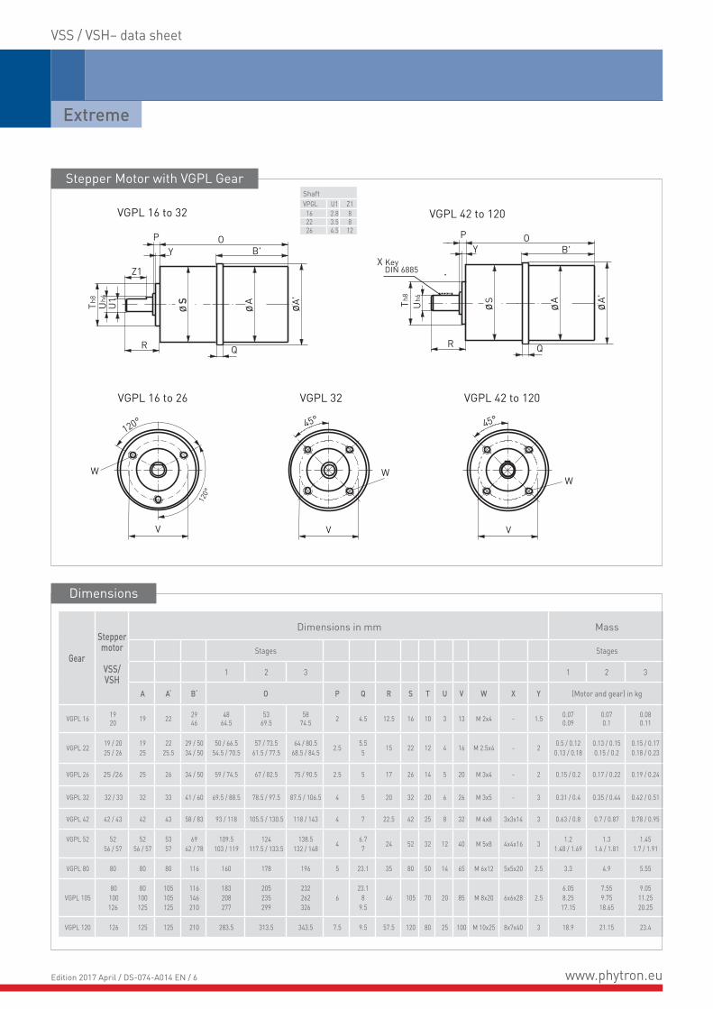
ShaftVPGL U1 Z1 16 2.8 8 22 3.5 8 26 4.5 12
Gear
Steppermotor
VSS/VSH
Dimensions in mm Mass
Stages Stages
1 2 3 1 2 3
A A‘ B‘ O P Q R S T U V W X Y (Motor and gear) in kg
VGPL 16 1920 19 22 29
46 48
64.553
69.558
74.5 2 4.5 12.5 16 10 3 13 M 2x4 - 1.5 0.070.09
0.070.1
0.080.11
VGPL 22 19 / 2025 / 26
1925
2225.5
29 / 5034 / 50
50 / 66.554.5 / 70.5
57 / 73.561.5 / 77.5
64 / 80.568.5 / 84.5 2.5 5.5
5 15 22 12 4 16 M 2.5x4 - 2 0.5 / 0.120.13 / 0.18
0.13 / 0.150.15 / 0.2
0.15 / 0.170.18 / 0.23
VGPL 26 25 /26 25 26 34 / 50 59 / 74.5 67 / 82.5 75 / 90.5 2.5 5 17 26 14 5 20 M 3x4 - 2 0.15 / 0.2 0.17 / 0.22 0.19 / 0.24
VGPL 32 32 / 33 32 33 41 / 60 69.5 / 88.5 78.5 / 97.5 87.5 / 106.5 4 5 20 32 20 6 26 M 3x5 - 3 0.31 / 0.4 0.35 / 0.44 0.42 / 0.51
VGPL 42 42 / 43 42 43 58 / 83 93 / 118 105.5 / 130.5 118 / 143 4 7 22.5 42 25 8 32 M 4x8 3x3x14 3 0.63 / 0.8 0.7 / 0.87 0.78 / 0.95
VGPL 52 5256 / 57
5256 / 57
5357
6962 / 78
109.5103 / 119
124117.5 / 133.5
138.5132 / 148 4 6.7
7 24 52 32 12 40 M 5x8 4x4x16 3 1.21.48 / 1.69
1.31.6 / 1.81
1.451.7 / 1.91
VGPL 80 80 80 80 116 160 178 196 5 23.1 35 80 50 14 65 M 6x12 5x5x20 2.5 3.3 4.9 5.55
VGPL 105 80
100126
80100125
105105125
116146210
183208277
205235299
232262326
623.1
89.5
46 105 70 20 85 M 8x20 6x6x28 2.56.058.25
17.15
7.559.75
18.65
9.0511.2520.25
VGPL 120 126 125 125 210 283.5 313.5 343.5 7.5 9.5 57.5 120 80 25 100 M 10x25 8x7x40 3 18.9 21.15 23.4
Dimensions
www.phytron.euEdition 2017 April / DS-074-A014 EN / 6

VSS / VSH– data sheet
Gear Stepper motor
Gear back-lash1)5)6)7) Rated torque4) 6)8) Gear inertia Radial
load2)Axialload
Efficiency at fullload3)
reduction ratioi [:1]
arc-min Nm kg cm2 N N %
Stage Stage Stage Stage
VSS/VSH 1 2 3 1 2 3 1 2 3 1 2 3 Stage1 Stage 2 Stage 3
VGPL 16 19 20 20 35 50 0.1 0.3 0.5 – – – 30 10
90 85 80
3 / 4 9 / 12 21 / 28 / 16
36 / 48 64 / 84
112 / 147 196
VGPL 22 19 / 20 25 / 26
1020
2035
30 50
0.1 0.5 1.5 0.008 0.006 0.004 30 24 4 / 5 16 / 20 28 / 35
64 / 80 112 / 140196 / 245
VGPL 26 2526 0.3 1 3 0.012 0.010 0.095 50 40 3.5 / 4.33 12.25 / 18.78
26 / 33.2281.37 / 112.67
143.96 / 199.33
VGPL 32 3233
820
1235
1550
0.40.8
24
66 0.015 0.012 0.011 80 65 4 / 4.5
5.2
12.08 / 16 18 / 20.8
25 / 2932 / 36 41.6
64 / 72 / 81 100 / 130144 / 200225 / 256
288
VGPL 42 4243
0.71.4
48
1212 0.03 0.024 0.024 150 120 3.5 / 4
5
12.25 / 1416 / 20 24 / 25
30 / 30.67 38.33
49 / 56 64 / 70 / 80 100 / 120 144 / 184
235.11 / 293.89
VGPL 52525657
620
1235
1550
1.53
1015
3030 0.06 0.055 0.05 250 200 4 / 4.5
5.2 / 6.25
12.08 / 16 18 / 20.8 25 / 29 32 / 36
41.6 / 50
64 / 72 / 81 100 / 130144 / 200 225 / 256 288 / 400
VGPL 80 80 36
1530
3838 0.12 0.08 0.075 400 320 3.5 / 4
5
12.25 / 1416 / 20 / 24
25 / 30 30.67 / 38.33
46
49 / 56 / 64 70 / 80 / 100
120 / 144 / 184235.11 / 293.89
VGPL 105 80100
1225
60120
150150 1 0.85 0.8
800 640 3.5 / 4 5
12.25 / 1416 / 2024 / 25
30 / 30.6738.33
49 / 5664 / 70 / 80100 / 120144 / 184
235.11 / 293.89
VGPL 105 126 800 640 3.5 / 412.25 / 14
16 / 20 24 / 30.67
49 / 56 64 / 70 / 80100 / 120144 / 184 235.11
VGPL 120 126 2550
130250
350350 1.75 1.4 1.35 1500 1200 3.5 / 4
5
12.25 / 1416 / 2024 / 25
30
49 / 56 64 / 7080 /100
120 / 144180
1) no load 2) center of the shaft 3) in grease-lubricated operation 4) continuous operation5) applies to FV, HV, UHVG for type reduced backlash 6) applies to FV, HV, UHVG for type low backlash 7) applies to UHVS, UHVC type standard backlash 8) type standard backlash
Mechanical Characteristics
www.phytron.euEdition 2017 April / DS-074-A014 EN / 7
Extreme
VSS / VSH – data sheet
Resolver Steppermotor A A‘ C X
Electrical Characteristics
Excit
ation
ampl
itude
[V
r.m.s.
]
Excit
ation
fre
quen
cy
[kHz
]
Tran
sfor-
mat
ion ra
tio
Roto
r ine
rtia
[gcm
2 ]
Mas
s [g]
(Res
olver
)
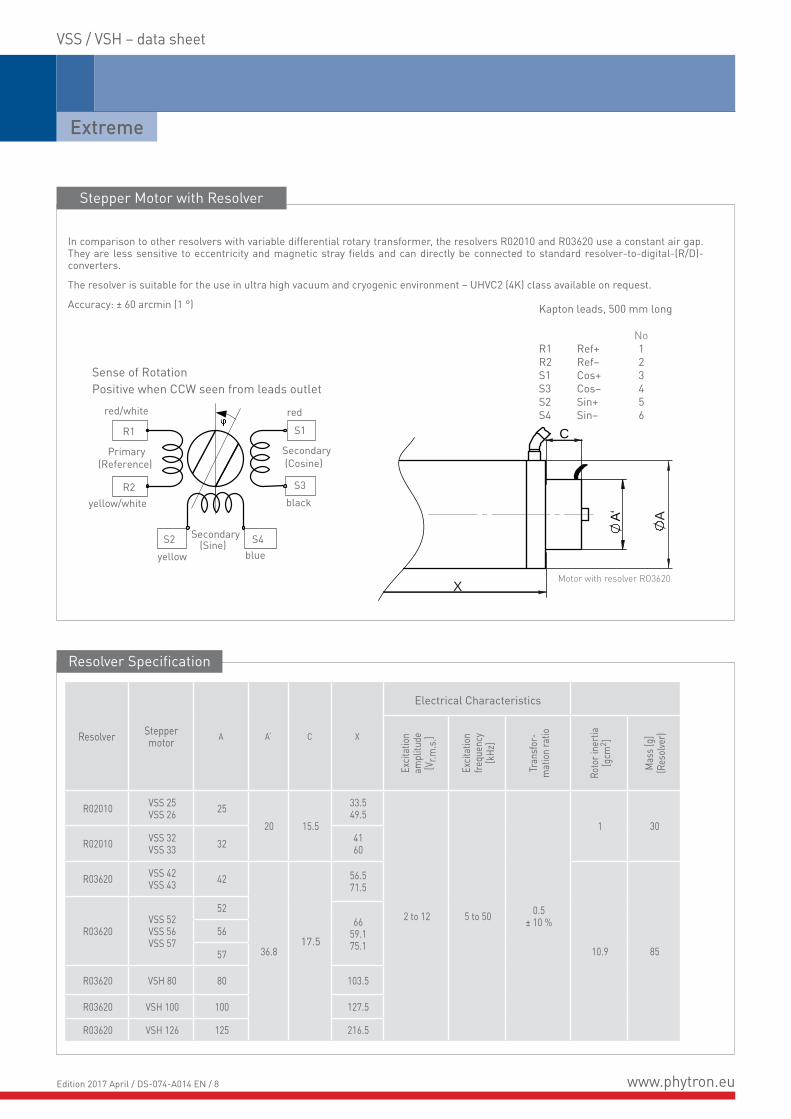
R02010 VSS 25VSS 26 25
20 15.5
33.549.5
2 to 12 5 to 50 0.5± 10 %
1 30R02010 VSS 32
VSS 33 32 4160
R03620 VSS 42VSS 43 42
36.817.5
56.571.5
10.9 85
R03620VSS 52VSS 56VSS 57
5266
59.175.1
56
57
R03620 VSH 80 80 103.5
R03620 VSH 100 100 127.5
R03620 VSH 126 125 216.5
Resolver Specification
Motor with resolver RO3620
Stepper Motor with Resolver
In comparison to other resolvers with variable differential rotary transformer, the resolvers R02010 and R03620 use a constant air gap. They are less sensitive to eccentricity and magnetic stray fields and can directly be connected to standard resolver-to-digital-(R/D)-converters.
The resolver is suitable for the use in ultra high vacuum and cryogenic environment – UHVC2 (4K) class available on request.
Accuracy: ± 60 arcmin (1 °)
A
A
‘
X
C R1
R2
S2 S4
S1
S3
Sense of RotationPositive when CCW seen from leads outlet
Primary(Reference)
Secondary(Sine)
Secondary(Cosine)
red/white
yellow/white
yellow blue
black
red
Kapton leads, 500 mm long
NoR1 Ref+ 1R2 Ref– 2S1 Cos+ 3S3 Cos– 4S2 Sin+ 5S4 Sin– 6
www.phytron.euEdition 2017 April / DS-074-A014 EN / 8
VSS / VSH – data sheet
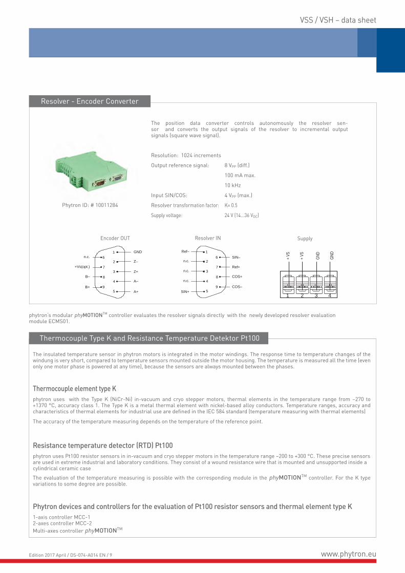
Resolver - Encoder Converter
Thermocouple Type K and Resistance Temperature Detektor Pt100
The position data converter controls autonomously the resolver sen-sor and converts the output signals of the resolver to incremental outputsignals (square wave signal).
Resolution: 1024 increments
Output reference signal: 8 VPP (diff.)
100 mA max.
10 kHz
Input SIN/COS: 4 VPP (max.)
Resolver transformation factor: K= 0.5
Supply voltage: 24 V (14...36 VDC)
The insulated temperature sensor in phytron motors is integrated in the motor windings. The response time to temperature changes of the windung is very short, compared to temperature sensors mounted outside the motor housing. The temperature is measured all the time (even only one motor phase is powered at any time), because the sensors are always mounted between the phases.
Thermocouple element type K phytron uses with the Type K (NiCr-Ni) in-vacuum and cryo stepper motors, thermal elements in the temperature range from –270 to +1370 °C, accuracy class 1. The Type K is a metal thermal element with nickel-based alloy conductors. Temperature ranges, accuracy and characteristics of thermal elements for industrial use are defined in the IEC 584 standard (temperature measuring with thermal elements)
The accuracy of the temperature measuring depends on the temperature of the reference point.
Resistance temperature detector (RTD) Pt100phytron uses Pt100 resistor sensors in in-vacuum and cryo stepper motors in the temperature range –200 to +300 °C. These precise sensors are used in extreme industrial and laboratory conditions. They consist of a wound resistance wire that is mounted and unsupported inside a cylindrical ceramic case
The evaluation of the temperature measuring is possible with the corresponding module in the phyMOTIONTM controller. For the K type variations to some degree are possible.
Phytron devices and controllers for the evaluation of Pt100 resistor sensors and thermal element type K1-axis controller MCC-1 2-axes controller MCC-2Multi-axes controller phyMOTIONTM
phytron‘s modular phyMOTIONTM controller evaluates the resolver signals directly with the newly developed resolver evaluation module ECMS01.
Phytron ID: # 10011284
+ VS
GND
GND
+ VS
1 2 3 4
6
7
8
9
1
2
3
4
5
n.c.
n.c.
n.c.
SIN+
SIN–Ref–
Ref+
COS+
COS–
6
7
8
9
1
2
3
4
5
n.c.
B+
+Vs(opt.)
B–
GND
Z–
Z+
A+
A–
SupplyResolver INEncoder OUT
www.phytron.euEdition 2017 April / DS-074-A014 EN / 9

Extreme
Stepper motor Dimensions in mm
Typ G1 H I
VSS19 2,5 2 4,5
VSS25 VSS26 3 2,5 6,5
VSS32VSS33 4 3,5 8
VSS 42VSS 43 5 4 13
VSS 52 6 5 14
VSS 56VSS 57 6,35 5,5 18,5
Dimensions
I
G
1
H
Option: Shaft design with flat surface
VSS / VSH – data sheet
More shaft options on demand.
www.phytron.euEdition 2017 April / DS-074-A014 EN / 10
VSS / VSH – data sheet
0
0
0.5 1 1.5 2 2.5 3 3.5 4
75 150 225 300 375 450 525 600
Frequency [kHz]
Speed [rev./min]
Torq
ue [m
Nm
]
Pow
er [W
]
VSS 19.200.0,6Half step mode
T (U = 70 V)
PSHAFT (U = 70 V)
00
0.5
1
1.5
2
2.5
3
0.05
0.1
0.15
0.2
0.25
0.3
0
0
0.5 1 1.5 2 2.5 3 3.5 4
75 150 225 300 375 450 525 600
Frequency [kHz]
Speed [rev./min]
Torq
ue [m
Nm
]
Pow
er [W
]
VSS 25.200.1,2Half step mode
00
2
4
6
8
10
12
0.2
0.4
0.6
0.8
1
1.2
T (U = 70 V)
PSHAFT (U = 70 V)
0
0
0.5 1 1.5 2 2.5 3 3.5 4
75 150 225 300 375 450 525 600
Frequency [kHz]
Speed [rev./min]
Torq
ue [m
Nm
]
Pow
er [W
]
VSS 20.200.0,6Half step mode
T (U = 70 V)
PSHAFT (U = 70 V)
00
1
2
3
4
5
6
0.1
0.2
0.3
0.4
0.5
0.6
0
0
0.5 1 1.5 2 2.5 3 3.5 4
75 150 225 300 375 450 525 600
Frequency [kHz]
Speed [rev./min]
Torq
ue [m
Nm
]
Pow
er [W
]VSS 26.200.1,2
Half step mode
00
3.5
7
10.5
14
17.5
21
0.2
0.4
0.6
0.8
1
1.2
T (U = 70 V)
PSHAFT (U = 70 V)
0
0
0.5 1 1.5 2 2.5 3 3.5 4
75 150 225 300 375 450 525 600
Frequency [kHz]
Speed [rev./min]
Torq
ue [m
Nm
]
Pow
er [W
]
VSS 33.200.0,6Half step mode
00
0
00.5 1 1.5 2 2.5 3 3.5 4
75 150 225 300 375 450 525 600
00
10
20
30
40
50
60
0.5
1
1.5
2
2.5
3
T (U = 70 V)
PSHAFT (U = 70 V)
0
0
0.5 1 1.5 2 2.5 3 3.5 4
75 150 225 300 375 450 525 600
Frequency [kHz]
Speed [rev./min]
Torq
ue [m
Nm
]
Pow
er [W
]
VSS 43.200.2,5Half step mode
00
0
00.5 1 1.5 2 2.5 3 3.5 4
75 150 225 300 375 450 525 600
00
35
70
105
140
175
210
2
4
6
8
10
12
T (U = 70 V)
PSHAFT (U = 70 V)
0
0
0.5 1 1.5 2 2.5 3 3.5 4
75 150 225 300 375 450 525 600
Frequency [kHz]
Speed [rev./min]
Torq
ue [m
Nm
]
Pow
er [W
]
VSS 32.200.1,2Half step mode
00
0
00.5 1 1.5 2 2.5 3 3.5 4
75 150 225 300 375 450 525 600
00
10
20
30
40
50
60
0.5
1
1.5
2
2.5
3
PSHAFT (U = 70 V)
T (U = 70 V)
0
0
0.5 1 1.5 2 2.5 3 3.5 4
75 150 225 300 375 450 525 600
Frequency [kHz]
Speed [rev./min]
Torq
ue [m
Nm
]
Pow
er [W
]
VSS 42.200.2,5Half step mode
00
0
00.5 1 1.5 2 2.5 3 3.5 4
75 150 225 300 375 450 525 600
00
20
40
60
80
100
120
1
2
3
4
5
6
T (U = 70 V)
PSHAFT (U = 70 V)
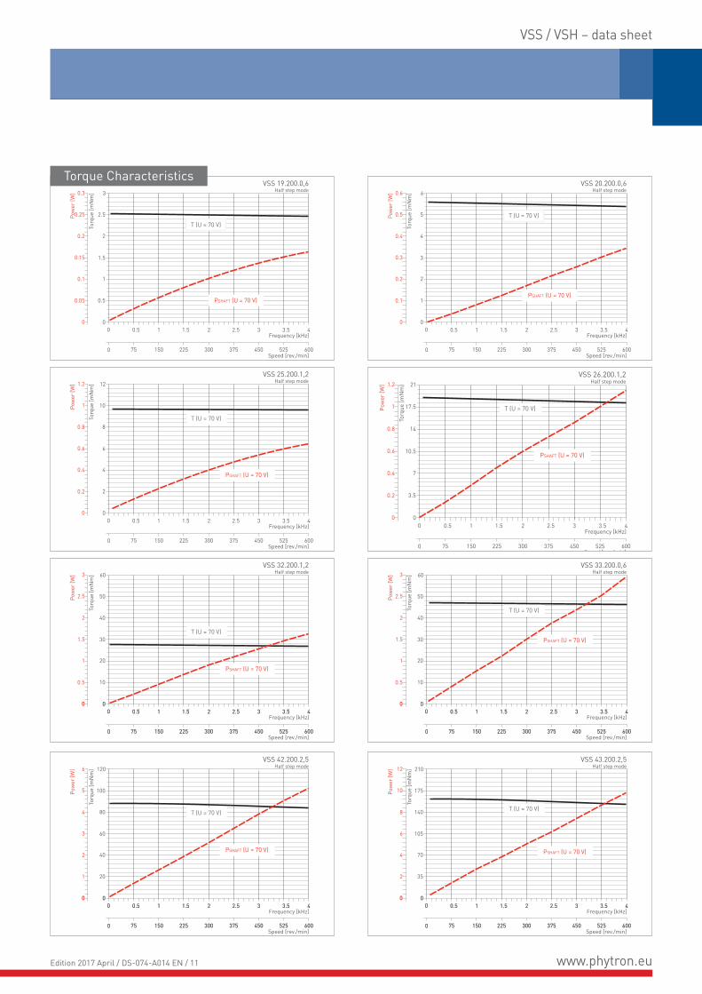
Torque Characteristics
www.phytron.euEdition 2017 April / DS-074-A014 EN / 11

Extreme
VSS / VSH – data sheet
0
0
0.5 1 1.5 2 2.5 3 3.5 4
75 150 225 300 375 450 525 600
Frequency [kHz]
Speed [rev./min]
Torq
ue [m
Nm
]
Pow
er [W
]
VSS 52.200.2,5Half step mode
00
0
00.5 1 1.5 2 2.5 3 3.5 4
75 150 225 300 375 450 525 600
00
50
100
150
200
250
300
3
6
9
12
15
18
T (U = 70 V)
PSHAFT (U = 70 V)
0
0
0.5 1 1.5 2 2.5 3 3.5 4
75 150 225 300 375 450 525 600
Frequency [kHz]
Speed [rev./min]
Torq
ue [m
Nm
]
Pow
er [W
]
VSS 57.200.2,5Half step mode
00
0
00.5 1 1.5 2 2.5 3 3.5 4
75 150 225 300 375 450 525 600
100
200
300
400
500
600
10
20
30
40
50
60
T (U = 70 V)
PSHAFT (U = 70 V)
0
0
0.5 1 1.5 2 2.5 3 3.5 4
75 150 225 300 375 450 525 600
Frequency [kHz]
Speed [rev./min]
Torq
ue [m
Nm
]
Pow
er [W
]
VSS 56.200.2,5Half step mode
00
0
00.5 1 1.5 2 2.5 3 3.5 4
75 150 225 300 375 450 525 600
00
50
100
150
200
250
300
3
6
9
12
15
18
T (U = 70 V)
PSHAFT (U = 70 V)
0
0
0.5 1 1.5 2 2.5 3 3.5 4
75 150 225 300 375 450 525 600
Frequency [kHz]
Speed [rev./min]
Torq
ue [N
m]
Pow
er [W
]
VSH 80.200.5Half step mode
00
0
00.5 1 1.5 2 2.5 3 3.5 4
75 150 225 300 375 450 525 600
00
0.5
1
1.5
2
2.5
3
20
40
60
80
100
120
T (U = 120 V)
PSHAFT (U = 120 V)
0
0
0.5 1 1.5 2 2.5 3 3.5 4
75 150 225 300 375 450 525 600
Frequency [kHz]
Speed [rev./min]
Torq
ue [N
m]
Pow
er [W
]
VSH 126.200.10Half step mode
00
2
4
6
8
10
12
100
200
300
400
500
600
T (U = 120 V)
PSHAFT (U = 120 V)
0
0
0.5 1 1.5 2 2.5 3 3.5 4
75 150 225 300 375 450 525 600
Frequency [kHz]
Speed [rev./min]
Torq
ue [N
m]
Pow
er [W
]
VSH 100.200.10Half step mode
00
1
2
3
4
5
6
50
100
150
200
250
300
T (U = 120 V)
PSHAFT (U = 120 V)
Torque Characteristics
U= 70 VDC / 120 VDC: Operating voltage of the power stage (intermediate circuit voltage)
www.phytron.euEdition 2017 April / DS-074-A014 EN / 12

VSS / VSH – data sheet
Adjustment of particle accelerator cavities
• stepper motor with 200 steps/revolution (1.8°), with integrated gear 50:1 (10:000 steps/revolution)
• designed for 1300 N axial force• spindle and nut system, non-magnetic • material for housing, flanges and internal parts stainless steel
or titanium• dry lubricated for usage under vacuum at -270 °C up to +40 °C
(also as grease lubricated version for environments > 35 °C)• optional EMC cable shielding• thermocouple K-type in winding
Efficient Customising - the perfect fit
Combine efficiently standard components, modifications & specials
Applications
Stepper motor spindle version for a particle accelerator (Cavity Tuner)
For 30 years we have used our know-how in a lot of successful space projects to optimise our vacuum series for industrial and scientific applications in the matter of performance and cost efficiency. The specific designs of the two-phase hybrid stepper motors have been designed for use in vacuum up to 10-11 hPa. Phytron vacuum step-per motors are conditionend at up to 250 °C for use in the high-(HV) or ulta-high vacuum (UHV) and are designed dependent on the applications for the low-temperature range up to -196 °C (N2), -269 °C (He), or high-temperature range (winding temperature up to +300 °C) and, if necessary, also for radiation up to 106 J/kg.
Starting from the VSS/VSH series we have already implemented a number of customer specific projects. Performance, housings, flanges, materials, shaft machining – in the common specification process, the VSS/VSH platform can be optimised for your project. With our high in-house production depth we are not only technolo-gically very flexible, we can also produce small quantities.
Our vacuum motors, power stages or controllers are driving in a lot of different applications:
• Particle accelerators and X-ray measuring systems (PETRA III, PANTER, FERMI, PAL, SOLEIL,...)• Devices for molecular analysis• Electron microscope• Sputtering systems• Cryostats• Mass spectrometry
www.phytron.euEdition 2017 April / DS-074-A014 EN / 13

Extreme
VSS / VSH – data sheet
Motion controller for vacuum application: phyMOTIONTM
Software environment to develop and realise distributed control systems for large-scale experiments such as telescopes and accelerators. EPICS provides the SCADA support.
Phytron delivers the source code to integrate the phytron controller phyMOTIONTM into EPICS environment.Also in multi-axis operation: positioning, limit-switches, encoder evaluation
Modular stepper motor controller for in-vacuum applications
Control via Android-based integrated touch panel (TPM01) or via Android-based tablets (from version V4.0)
• As user interface i.e. for parameter selection• For support, parameterisation and diagnostics
Temperature evaluation module for stepper motor temperature monitoring
Thermal elements type K or Pt100 resistor sensors can be used. The insulated temperature sensor in phytron motors is integrated in the motor windings. The response time is very short. The temperature is measured all the time, even if only one motor phase is powered at any one time.
Encoder types suitable for the encoder evaluation:
• Differential incremental encoder with Quadratic signals• Absolute encoder acc. to SSI standard• EnDat encoder• Resolver
The phyMOTIONTM controller is ideally equipped for the demands of in-vacuum projects. Beside the encoder evaluation (differential incremental encoder with quadrature signals, absolute encoder acc. to SSI standard, EnDat-encoder) a resolver and temperature sensor evaluation of each axis is possible for monitoring of the dri-ven motors. This functions can be integrated as optional submo-dules of each axis – in addition to the default limit switch evalua-tions of each axis. So, you pay only what you really need. The better part of cabling effort is eliminated because the power stages are already integrated.
You can combine with 6 to 21 modules of each housing up to 18 power stages with different functions (axis modules, digital I/O, analogue I/O, 4-axis indexer for interpolation, integrated display)
Via freely selectable HOST interface (ProfiBus, ProfiNet, Ether-net, RS232, RS484, USB, Bluetooth) and provided drivers and protocols (LabVIEW® VI, EPICS) you can seamlessly integrate the phyMOTIONTM also below existing systems.
Operate the phyMOTIONTM as free programable stand-alone con-troller, as distributed intelligence, or also as a slave system i.e. below existing PLC systems.
VIs for phyMOTIONTM – simulation software with graphical style
Use the VIs (Virtual instruments) generated by Phytron and integrate them in your LabVIEW® project. So you can easily control the phytron controller phyMOTIONTM from your usual programming environment.
LabVIEW®-VI
www.phytron.euEdition 2017 April / DS-074-A014 EN / 14

Extreme
VSS / VSH – data sheet
Optio
ns
Step
reso
lutio
n
Optio
n VP
GLSize
Type
Optio
n E
Rate
d cur
rent
Ordering code
The variable elements of the product are displayed in colour.
VSS / VSH 42 200 2,5. - E VGPL 42 / 20- HV-.
W1
W4
W3
W2
8-lead
unipolaror bipolar control
yellowblackbrownred
bluevioletwhitegreen
Phas
e 1
Phas
e 2
AEGB
CHFD
Begin of the winding
Windings parallel Windings in series
AB
CD
CD
AB
yellowred
bluegreen
yellowred
bluegreen
Stan
dard
W1
W4
W3
W2
W1
W4
W3
W2
4-lead
bipolarcontrol
Electrical Connection
KTC-
Vacu
um cl
ass
Size 19 - 125
Rated current (A/Phase) 0,61,22,55 10
for VSS 19 to 33for VSS 19 to 57for VSS 42 to 57for VSH 80 for VSH 100 to VSH 126
Option E E Double shaftno double shaft
Option VGPL VGPL xx/xx Low backlash gear: size / reduction rationo gear
Vacuum class HVUHVSUHVGUHVC1UHVC2
High vacuumUltra high vacuum dry coated bearingUltra high vacuum greased bearingUltra high vacuum Cryo temperature down to liquid NitrogenUltra high vacuum Cryo temperature down to liquid Helium
Options RKTCPt RSX
Radial wire outletThermocouple type K*)
Resistance temperature detectorResolvercustomisedno
Ordering Code
Options Admissible phase currentsfor identical power dissipation
Bipolar control modeFull step operation
4-lead motor 4-lead motor
parallel windings series windings
rated current 50% of the rated current
Phase currents
*) Standard for vacuum class UHVS and UHVG.
All illustrations, descriptions and technical specifications are subject to modifications; no responsibility is accepted for the accuracy of this information.
www.phytron.euEdition 2017 April / DS-074-A014 EN / 15
Phytron GmbHIndustriestraße 12 – 82194 Gröbenzell
T +49-8142-503-0 F +49-8142-503-190


![[XLS]irtfweb.ifa.hawaii.eduirtfweb.ifa.hawaii.edu/~s2/design/s2-ldog-upgrade/ishell... · Web viewDrawing Summary Vern's Mechanism Summary Portescap IMS Galil Phytron Specs & Prices](https://img.pdfslide.us/doc/110x75/5b2586e97f8b9a353f8b4fae/xls-s2designs2-ldog-upgradeishell-web-viewdrawing-summary-verns-mechanism.jpg)