Embed Size (px)
Citation preview
For the operator/for the heating engineer
Operating and Installation Manual
VRC 430
Weather compensator VRC 430
GB

For the operator
Operating Manual
VRC 430
VRC 430Weather compensator
Contents
Appliance features .....................................................4Application ............................................................................4Product features ..................................................................4
1 Notes on the documentation .........................51.1 Storing of the documents .....................................51.2 Symbols used ...........................................................51.3 Applicability of the manual ...................................51.4 CE label ......................................................................5
2 Safety ...............................................................5
3 Notes on operation .........................................63.1 Intended use .............................................................63.2 Environmental conditions .....................................63.3 Care ............................................................................63.4 Vaillant warranty.....................................................63.5 Recycling and disposal ..........................................6
4 Operation ......................................................... 74.1 Overview operating and display front ...............74.2 Overview of the display (display field) ..............8
4.3 Operating concept ..................................................84.3.1 Show various display screens ..............................94.3.2 Changing parameters.............................................94.3.3 Operation in the simplified basic display ..........114.4 The period of validity for new control
system target values .............................................124.5 Operator level, Expert technician level ............134.6 Screens in the operating level for the
operator ....................................................................134.7 Changing the displays (examples) .................... 154.7.1 Entering time programmes (example for
heating circuit) ...................................................... 154.7.2 Programming holiday periods ........................... 164.7.3 Entering parameters for the heating
circuit ........................................................................174.7.4 Entering parameters for hot water
generation ............................................................... 184.7.5 Renaming the heating components ................. 18
5 Status and error messages. .........................19
Operating Manual VRC 430 0020042468_024
Appliance features
ApplicationThe VRC 430 is a weather compensator controller for heating and generating hot water.
"Weather compensator" means: at low external tem-peratures the VRC 430 provides more heating output, and at higher external temperatures lower heating output. The outside temperature is measured by a separate outdoor sensor, and the results are transmit-ted to the VRC 430.The room temperature is based only on your preset values. The system compensates for the effect of the external temperature.
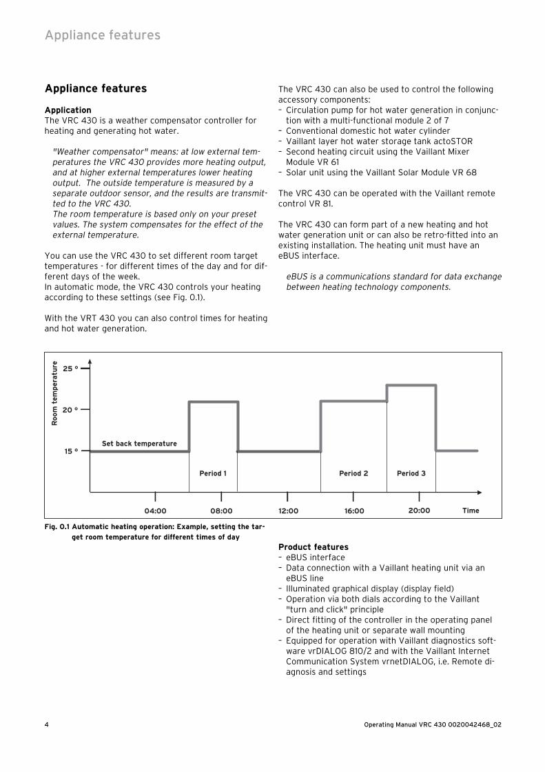
You can use the VRC 430 to set different room target temperatures - for different times of the day and for dif-ferent days of the week.In automatic mode, the VRC 430 controls your heating according to these settings (see Fig. 0.1).
With the VRT 430 you can also control times for heating and hot water generation.
04:00 16:0008:00 12:00 20:00
15 °
20 °
25 °
Room
tem
per
atu
re
Time
Set back temperature
Period 1 Period 3Period 2
Fig. 0.1 Automatic heating operation: Example, setting the tar-
get room temperature for different times of day
The VRC 430 can also be used to control the following accessory components:– Circulation pump for hot water generation in conjunc-
tion with a multi-functional module 2 of 7– Conventional domestic hot water cylinder– Vaillant layer hot water storage tank actoSTOR– Second heating circuit using the Vaillant Mixer
Module VR 61– Solar unit using the Vaillant Solar Module VR 68
The VRC 430 can be operated with the Vaillant remote control VR 81.
The VRC 430 can form part of a new heating and hot water generation unit or can also be retro-fitted into an existing installation. The heating unit must have an eBUS interface.
eBUS is a communications standard for data exchange between heating technology components.
Product features– eBUS interface– Data connection with a Vaillant heating unit via an
eBUS line – Illuminated graphical display (display field)– Operation via both dials according to the Vaillant
"turn and click" principle– Direct fitting of the controller in the operating panel
of the heating unit or separate wall mounting– Equipped for operation with Vaillant diagnostics soft-
ware vrDIALOG 810/2 and with the Vaillant Internet Communication System vrnetDIALOG, i.e. Remote di-agnosis and settings
Appliance features
5Operating Manual VRC 430 0020042468_02
1 Notes on the documentation
The following information is intended to help you work through the documentation. Additional documents apply in combination with this operating manual.We accept no liability for any damage caused by failure to observe these instructions.
Other applicable documents– The installation instructions for the Vaillant controller
VRC 430 (Section 2 of this document For the expert technician:
– The operating and installation manual for your heat-ing system
– All instructions for accessory components
Glossary:At the end of this document, in the appendix, you will find an explanation of technical terms and important functions listed in alphabetical order.
1.1 Storing of the documentsPlease store this operating manual and all related docu-ments in such a way that they are available whenever required.
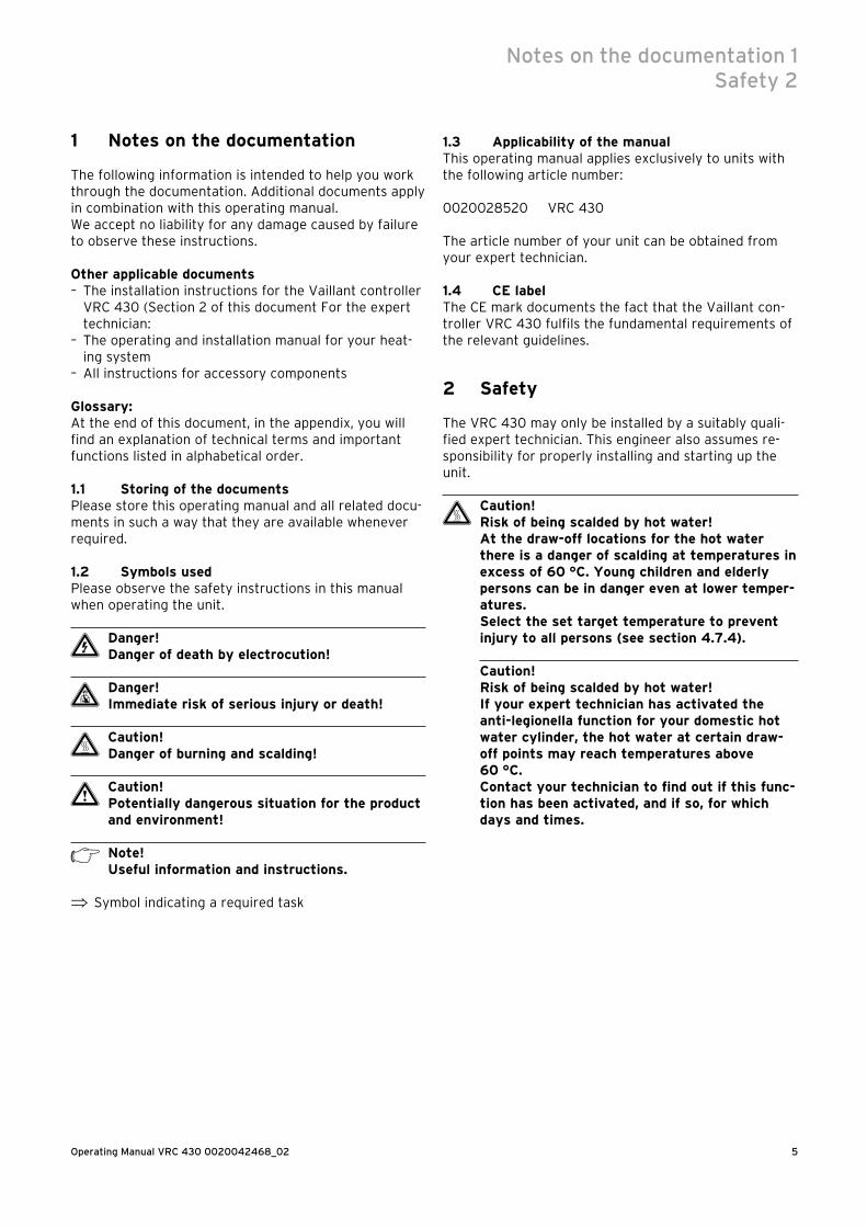
1.2 Symbols usedPlease observe the safety instructions in this manual when operating the unit.
e Danger!Danger of death by electrocution!
d Danger!Immediate risk of serious injury or death!
H Caution!Danger of burning and scalding!
a Caution!Potentially dangerous situation for the product and environment!
h Note!Useful information and instructions.
⇒ Symbol indicating a required task
1.3 Applicability of the manualThis operating manual applies exclusively to units with the following article number:
0020028520 VRC 430
The article number of your unit can be obtained from your expert technician.
1.4 CE labelThe CE mark documents the fact that the Vaillant con-troller VRC 430 fulfils the fundamental requirements of the relevant guidelines.
2 Safety
The VRC 430 may only be installed by a suitably quali-fied expert technician. This engineer also assumes re-sponsibility for properly installing and starting up the unit.
H Caution!Risk of being scalded by hot water!At the draw-off locations for the hot water there is a danger of scalding at temperatures in excess of 60 °C. Young children and elderly persons can be in danger even at lower temper-atures.Select the set target temperature to prevent injury to all persons (see section 4.7.4).
Caution!Risk of being scalded by hot water!If your expert technician has activated the anti-legionella function for your domestic hot water cylinder, the hot water at certain draw-off points may reach temperatures above 60 °C.Contact your technician to find out if this func-tion has been activated, and if so, for which days and times.
Notes on the documentation 1Safety 2

Operating Manual VRC 430 0020042468_026
3 Notes on operation
3 Notes on operation
3.1 Intended useThe VRC 430 weather compensator is a state-of-the-art appliance manufactured in accordance with recognised safety regulations.However, damage and property may occur if the unit is used improperly or for a purpose other than the intend-ed purpose.
The VRC 430 controller is designed as a weather com-pensator timer-controlled heating unit with or without hot water generation/circulation pump in conjunction with a Vaillant boiler with eBUS interface.Operation with the following accessories is permitted:
– Circulation pump for hot water generation in conjunc-tion with a multi-functional module 2 of 7
– Conventional domestic hot water cylinder– Vaillant layer hot water storage tank actoSTOR– Second heating circuit using the Vaillant Mixer
Module VR 61– Solar unit using the Vaillant Solar Module VR 68– VR 81 remote control device
Any other or extended use is considered to be use other than intended. The manufacturer or supplier is not liable for any resulting damage. The owner alone bears any risk.Intended use also includes observing the operating and installation instructions and all other applicable docu-ments.
3.2 Environmental conditionsIf the "thermostat" function is active and the VR 81 re-mote control unit is not connected, please ensure:– the unit is not blocked by furniture or other obstacles.– the radiator valves in the room in which the VRC 430
is fitted are fully open.
"room temperature compensation" means that the current room temperature is evaluated by the VRC 430 and taken into account in the control sys-tem.
Your expert technician will advise you whether the "room temperature compensation" is activated.
3.3 CareClean the enclosure of the VRC 430 with a damp cloth.Never use scouring or cleaning agents which could dam-age the operating elements or the display.
3.4 Vaillant warrantyWe only grant a Vaillant manufacturer's warranty if a suitably qualified engineer has installed the system in accordance with Vaillant instructions. The system owner will be granted a warranty in accordance with the Vaillant terms and conditions. All requests for work dur-ing the guarantee period must be made to Vaillant Service Solutions (ane 0870 6060 777).
3.5 Recycling and disposalBoth your VRC 430 and its packaging are primarily made of recyclable raw materials.
ApplianceNeither the VRC 430 nor any of its accessories may be disposed of in the household waste. Make sure the old appliance and any accessories are disposed of properly.
PackagingPlease leave the disposal of the transport packaging to the qualified servicing company which installed the ap-pliance.
7Operating Manual VRC 430 0020042468_02
4 Operation
h Note! Ask your expert technician to explain how to operate the VRC unit after it has been in-stalled. This will prevent accidental changes being made to the settings.
4.1 Overview operating and display front
Th. 12.01.0611:46
3.0 °C Outside
Auto 19.0 °CVRC 430
23
1
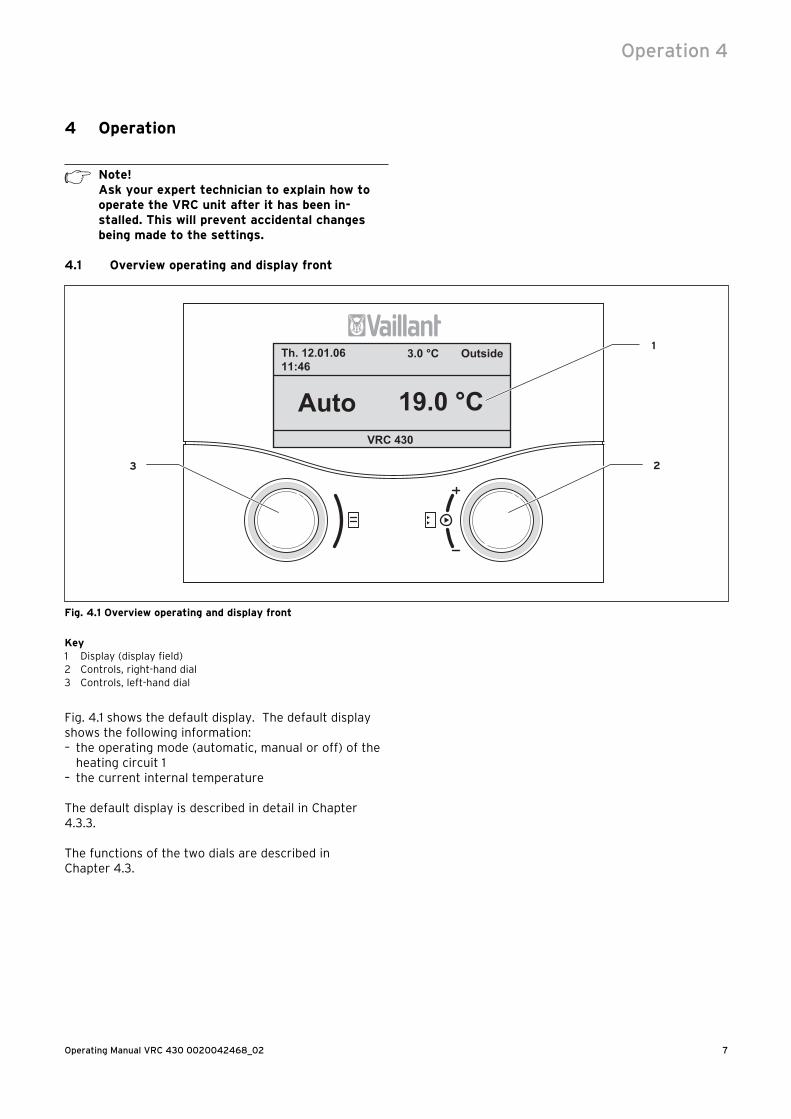
Fig. 4.1 Overview operating and display front
Key1 Display (display field)2 Controls, right-hand dial3 Controls, left-hand dial
Fig. 4.1 shows the default display. The default display shows the following information:– the operating mode (automatic, manual or off) of the
heating circuit 1– the current internal temperature
The default display is described in detail in Chapter 4.3.3.
The functions of the two dials are described in Chapter 4.3.
Operation 4
Operating Manual VRC 430 0020042468_028
4.2 Overview of the display (display field)The parameters (operating values) of the controller for display and entry are shown on the various display screens.The display screens are sub-divided into:– Default display (Fig. 4.1)– Basic display (Fig. 4.2)– Display/input screens for certain specific parameters
in the operator level (see Chapter 4.4 and 4.5)– Display/input screens for operating and installation-
specific parameters at installer level
All display screens are split into three areas.
56.0 °C
Auto
> Select room temperature
� 21.0 °C
Th. 12.01.0611:46
3.0 °C Outside
HC1
Auto DHW
1
2
3
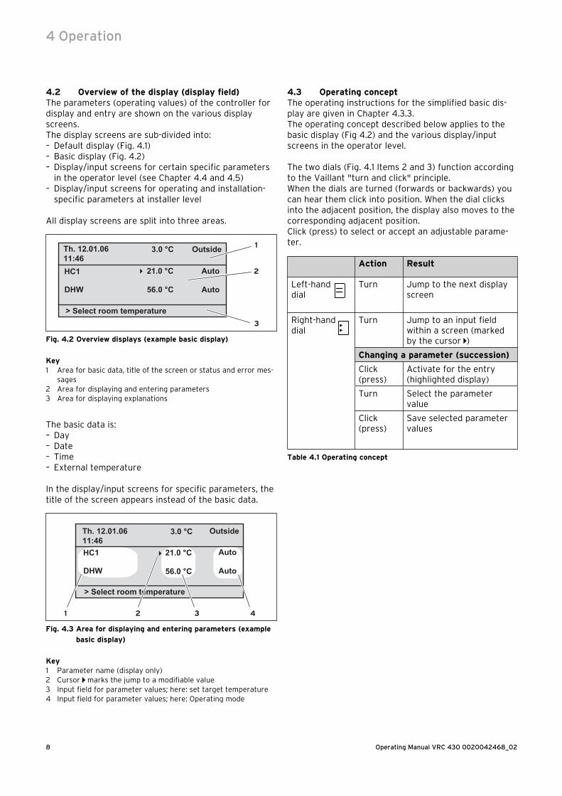
Fig. 4.2 Overview displays (example basic display)
Key1 Area for basic data, title of the screen or status and error mes-
sages2 Area for displaying and entering parameters3 Area for displaying explanations
The basic data is:– Day– Date– Time– External temperature
In the display/input screens for specific parameters, the title of the screen appears instead of the basic data.
> Select room temperature
Th. 12.01.0611:46
3.0 °C Outside
HC1
DHW 56.0 °C
21.0 °C � Auto
Auto
1 2 3 4
Fig. 4.3 Area for displaying and entering parameters (example
basic display)
Key1 Parameter name (display only)2 Cursor marks the jump to a modifiable value3 Input field for parameter values; here: set target temperature4 Input field for parameter values; here: Operating mode
4.3 Operating conceptThe operating instructions for the simplified basic dis-play are given in Chapter 4.3.3.The operating concept described below applies to the basic display (Fig 4.2) and the various display/input screens in the operator level.
The two dials (Fig. 4.1 Items 2 and 3) function according to the Vaillant "turn and click" principle.When the dials are turned (forwards or backwards) you can hear them click into position. When the dial clicks into the adjacent position, the display also moves to the corresponding adjacent position.Click (press) to select or accept an adjustable parame-ter.
Action Result
Left-hand dial
Turn Jump to the next display screen
Right-handdial
Turn Jump to an input field within a screen (marked by the cursor )
Changing a parameter (succession)
Click (press)
Activate for the entry (highlighted display)
Turn Select the parameter value
Click (press)
Save selected parameter values
Table 4.1 Operating concept
4 Operation

9Operating Manual VRC 430 0020042468_02
4.3.1 Show various display screensYou can scroll through the individual screens of the dis-play, like you do with a book, by turning the left-hand dial.
Example:You are now in the basic display. Instructions for ac-cessing the basic display are given in Chapter 4.3.3
⇒ Turn the left-hand dial one position (click) clockwise.
The screen now shows display page 1 with the options for making changes to the basic data.
56.0 °C
Auto
> Select room temperature
� 21.0 °C
Th. 12.01.0611:46
3.0 °C Outside
HC1
Auto DHW
Day of week We12 : 00
> Set day of week
�
21 . 06 . 06
Basic data 1
Date
Time
1
> Select day of week
�
21.5 °C
HC1 2
Mo
2
Time programme
3
06 : 00 - 10 : 40 : - : : - :
Auto Summer/winter time changeover
Fig. 4.4 Displaying various screens
4.3.2 Changing parameters⇒ Rotate the right-hand adjuster to jump to the indi-
vidual modifiable parameters within the display screen.
The position is indicated by the cursor (see Fig. 4.5).
If a parameter (e.g. a date with day, month, year) has several elements, jump from one element to the next by rotating the right-hand dial.
56.0 °C
Auto
> Select room temperature
�
Th. 12.01.0611:46
3.0 °C Outside
HC1
Auto DHW
21.0 °C
56.0 °C
Auto
> Select operation mode
�
Th. 12.01.0611:46
3.0 °C
HC1
Auto DHW
21.0 °C
56.0 °C
Auto
> Select target hot water
�
Th. 12.01.0611:46
3.0 °C
HC1
Auto DHW
21.0 °C
Outside
Outside
Fig. 4.5 Jump to the various modifiable parameters
Operation 4
Operating Manual VRC 430 0020042468_0210
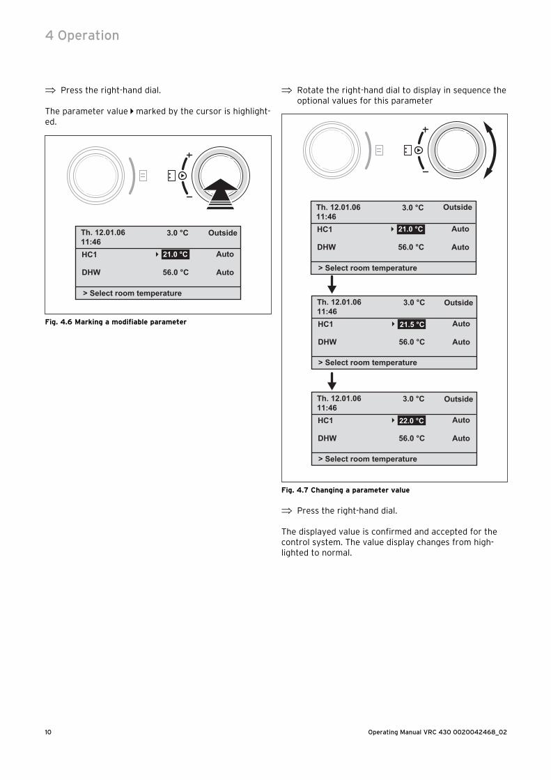
⇒ Press the right-hand dial.
The parameter value marked by the cursor is highlight-ed.
56.0 °C
Auto
> Select room temperature
�
Th. 12.01.0611:46
3.0 °C Outside
HC1
Auto DHW
21.0 °C
Fig. 4.6 Marking a modifiable parameter
⇒ Rotate the right-hand dial to display in sequence the optional values for this parameter
56.0 °C
Auto
> Select room temperature
�
Th. 12.01.0611:46
3.0 °C Outside
HC1
Auto DHW
21.0 °C
56.0 °C
Auto �
Th. 12.01.0611:46
3.0 °C
HC1
Auto DHW
21.5 °C
56.0 °C
Auto �
Th. 12.01.0611:46
3.0 °C
HC1
Auto DHW
22.0 °C
Outside
Outside
> Select room temperature
> Select room temperature
Fig. 4.7 Changing a parameter value
⇒ Press the right-hand dial.
The displayed value is confirmed and accepted for the control system. The value display changes from high-lighted to normal.
4 Operation
11Operating Manual VRC 430 0020042468_02
Changing the parameters in the basic display
Parameters Meaning
Hea
tin
g c
ircu
it 1
(H
C1)
Room set tar-gettemperature
The heating is adjusted according to the modified room target temperature. The length of this control period de-pends on the operating mode, see also Chapter 4.4.
Operating modeAuto(matic)
The control system of the heating unit is according to the stipulation of the room target temperature, the time programme and other parameters such as set-back temperature and heating curve.Some of these parameters are set by your expert technician.
Operating modeManual
The control system of the heating unit is according to the set room target temperature.
Operating modeOff
The heating unit is switched off. The target room temperature is not dis-played and can therefore not be changed.Frost protection is guaranteed.
Hot
wate
r
Hot water tar-get value
Hot water generation is generated ac-cording to the new target hot water value. The duration of this control sys-tem depends upon the operating mode, see also Chapter 4.4.
Operating modeAuto(matic)
The hot water is generated according to the target hot water temperature and time settings.
Operating modeManual
The hot water control system is based on the hot water target value.
Operating modeOff
Hot water generation is switched off. The target hot water value is not dis-played and is also not modifiable.Frost protection is guaranteed.
Table 4.2 Modifiable parameters in the basic display
Example: Changing the heating circuit target room temperature 1 (HC1)Initial situation: You are now in the basic screen (see Fig. 4.2). Instructions for accessing the basic display are given in Chapter 4.3.3
⇒ Turn the right-hand dial until the cursor appears in front of the target value (target room temperature) for heating circuit 1 (HC1).
⇒ Press the right-hand dial.
The input field for the set target value is highlighted.
⇒ Turn the right-hand dial.
The target room temperature changes by 0.5 °C for every dial position (click).
⇒ When you reach the required room target temperature , Press the right-hand dial.
The new value is set. The display jumps highlighted to normal.
The period for which the new control system value re-mains valid depends on the current operating mode; 4.4
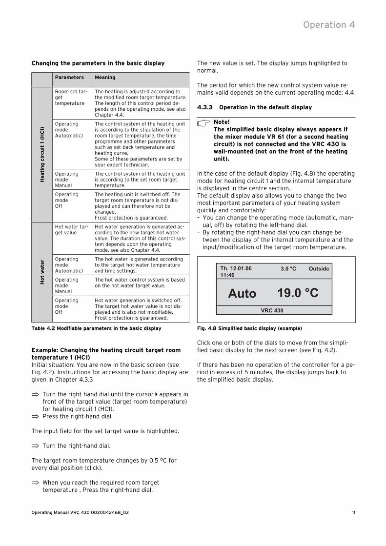
4.3.3 Operation in the default display
h Note!The simplified basic display always appears if the mixer module VR 61 (for a second heating circuit) is not connected and the VRC 430 is wall-mounted (not on the front of the heating unit).
In the case of the default display (Fig. 4.8) the operating mode for heating circuit 1 and the internal temperature is displayed in the centre section.The default display also allows you to change the two most important parameters of your heating system quickly and comfortably:– You can change the operating mode (automatic, man-
ual, off) by rotating the left-hand dial.– By rotating the right-hand dial you can change be-
tween the display of the internal temperature and the input/modification of the target room temperature.
Th. 12.01.0611:46
3.0 °C Outside
Auto 19.0 °CVRC 430
Fig. 4.8 Simplified basic display (example)
Click one or both of the dials to move from the simpli-fied basic display to the next screen (see Fig. 4.2).
If there has been no operation of the controller for a pe-riod in excess of 5 minutes, the display jumps back to the simplified basic display.
Operation 4
Operating Manual VRC 430 0020042468_0212
Changing the operating mode in the simplified basic display
Operating mode
Meaning
Auto(matic) The heating circuit is controlled according to the target room temperature, the timer pro-grammes, as well as other parameters such as set-back temperature and heating curve.Some of these parameters are set by your ex-pert technician.
Manual The heating circuit is controlled according to the room target temperature.
Off The heating circuit is switched off. The target room temperature is not displayed and also cannot be changed.Frost protection is guaranteed.
Table 4.3 Operating modes for the heating unit
Proceed as follows:
⇒ Rotate the left-hand dial.
The operating mode is highlighted.After a delay of 1 second, you can select the operating mode by rotating the left-hand dial.After 2 seconds, the display returns to normal.The selected operating mode is accepted.
Th. 12.01.0611:46
3.0 °C Outside
Manual 19.0 °C> Select operation mode
Fig. 4.9 Changing the operating mode in the default display
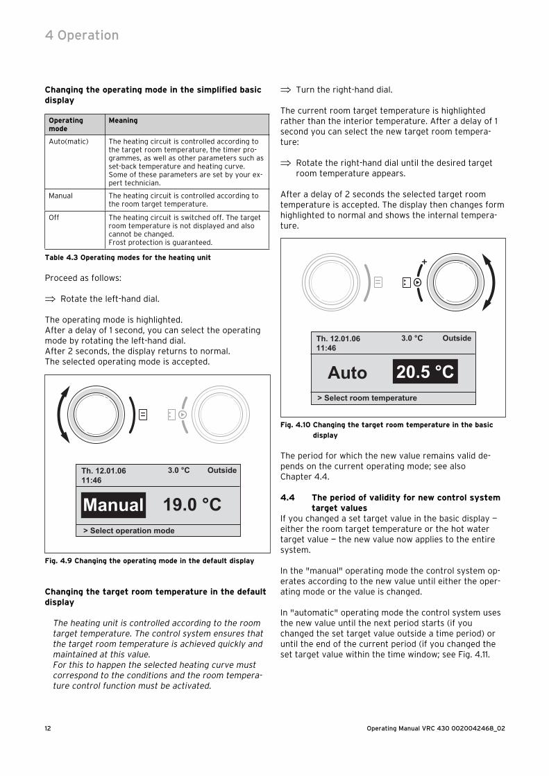
Changing the target room temperature in the default display
The heating unit is controlled according to the room target temperature. The control system ensures that the target room temperature is achieved quickly and maintained at this value. For this to happen the selected heating curve must correspond to the conditions and the room tempera-ture control function must be activated.
⇒ Turn the right-hand dial.
The current room target temperature is highlighted rather than the interior temperature. After a delay of 1 second you can select the new target room tempera-ture:
⇒ Rotate the right-hand dial until the desired target room temperature appears.
After a delay of 2 seconds the selected target room temperature is accepted. The display then changes form highlighted to normal and shows the internal tempera-ture.
Th. 12.01.0611:46
3.0 °C Outside
Auto 20.5 °C> Select room temperature
Fig. 4.10 Changing the target room temperature in the basic
display
The period for which the new value remains valid de-pends on the current operating mode; see also Chapter 4.4.
4.4 The period of validity for new control system target values
If you changed a set target value in the basic display — either the room target temperature or the hot water target value — the new value now applies to the entire system.
In the "manual" operating mode the control system op-erates according to the new value until either the oper-ating mode or the value is changed.
In "automatic" operating mode the control system uses the new value until the next period starts (if you changed the set target value outside a time period) or until the end of the current period (if you changed the set target value within the time window; see Fig. 4.11.
4 Operation
13Operating Manual VRC 430 0020042468_02
08:00 12:00
15 °
20 °
25 °
Room
tem
per
atu
re
Time
Period
08:00 12:00
15 °
20 °
25 °
Time
Period
2 3
4
1
Set backtemperature
Room
tem
per
atu
re
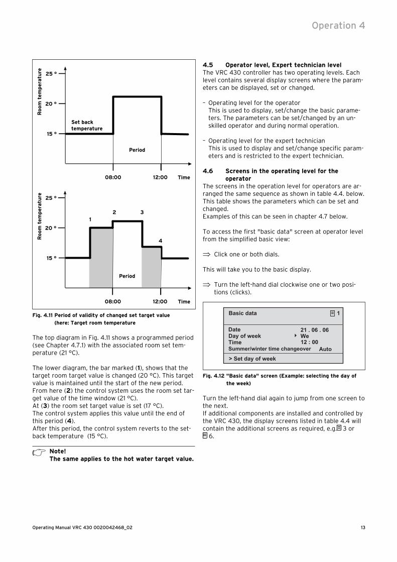
Fig. 4.11 Period of validity of changed set target value
(here: Target room temperature
The top diagram in Fig. 4.11 shows a programmed period (see Chapter 4.7.1) with the associated room set tem-perature (21 °C).
The lower diagram, the bar marked (1), shows that the target room target value is changed (20 °C). This target value is maintained until the start of the new period.From here (2) the control system uses the room set tar-get value of the time window (21 °C).At (3) the room set target value is set (17 °C).The control system applies this value until the end of this period (4).After this period, the control system reverts to the set-back temperature (15 °C).
h Note!The same applies to the hot water target value.
4.5 Operator level, Expert technician levelThe VRC 430 controller has two operating levels. Each level contains several display screens where the param-eters can be displayed, set or changed.
– Operating level for the operatorThis is used to display, set/change the basic parame-ters. The parameters can be set/changed by an un-skilled operator and during normal operation.
– Operating level for the expert technicianThis is used to display and set/change specific param-eters and is restricted to the expert technician.
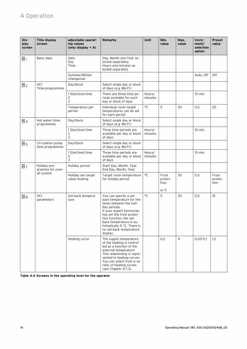
4.6 Screens in the operating level for the operator
The screens in the operation level for operators are ar-ranged the same sequence as shown in table 4.4. below. This table shows the parameters which can be set and changed.Examples of this can be seen in chapter 4.7 below.
To access the first "basic data" screen at operator level from the simplified basic view:
⇒ Click one or both dials.
This will take you to the basic display.
⇒ Turn the left-hand dial clockwise one or two posi-tions (clicks).
Day of week We12 : 00
> Set day of week
�
21 . 06 . 06
Basic data 1
Date
Time Summer/winter time changeover Auto
Fig. 4.12 "Basic data" screen (Example: selecting the day of
the week)
Turn the left-hand dial again to jump from one screen to the next.If additional components are installed and controlled by the VRC 430, the display screens listed in table 4.4 will contain the additional screens as required, e.g. 3 or
6.
Operation 4
Operating Manual VRC 430 0020042468_0214
Dis-play screen
Title display screen
adjustable operat-ing values (only display = A)
Remarks Unit Min.value
Max.value
Incre-ment/selection option
Preset value
1 Basic data DateDayTime
Day, Month and Year se-lected separately;Hours and minutes se-lected separately
Summer/Winter changeover
Auto, Off Off
2 HC1Time programmes
Day/block Select single day or block of days (e.g. Mo-Fr)
1 Start/end time23
There are three time pe-riods available for each day or block of days
Hours/minutes
10 min
Temperature per period
Individual room target temperatures can be set for each period
°C 5 30 0,5 20
4 Hot water timer programmes
Day/block Select single day or block of days (e.g. Mo-Fr)
1 Start/end time23
Three time periods are available per day or block of days
Hours/minutes
10 min
5 Circulation pump time programmes
Day/block Select single day or block of days (e.g. Mo-Fr)
1 Start/end time23
Three time periods are available per day or block of days
Hours/minutes
10 min
7 Holiday pro-gramme for over-all system
Holiday period Start Day, Month, YearEnd Day, Month, Year
Holiday set target value heating
Target room temperature for holiday period
°C Frost protec-tion,
or 5
30 0,5 Frost protec-tion
8 HC1parameters
Set-back tempera-ture
You can specify a set-back temperature for the times between the holi-day periods.If your expert technician has set the frost protec-tion function, the set-back temperature is au-tomatically 5 °C. There is no set-back temperature display.
°C 5 30 0,5 15
Heating curve The supply temperature of the heating is control-led as a function of the external temperature This relationship is repre-sented in heating curves. You can select from a va-riety of heating curves (see Chapter 4.7.3).
0,2 4 0,05-0,1 1,2
Table 4.4 Screens in the operating level for the operator
4 Operation
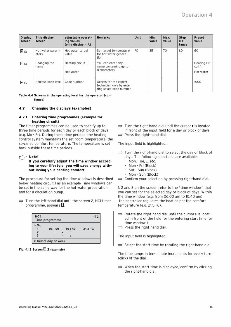
15Operating Manual VRC 430 0020042468_02
Display screen
Title display screen
adjustable operat-ing values (only display = A)
Remarks Unit Min.value
Max.value
Step dis-tance
Preset value
10 Hot water param-eters
Hot water target value
Set target temperature for hot water genera-tion
°C 35 70 1,0 60
14 Changing the name
Heating circuit 1 You can enter any name containing up to 8 characters
Heating cir-cuit 1
Hot water Hot water
15 Release code level Code number Access for the expert technician only by ente-ring saved code number
1000
Table 4.4 Screens in the operating level for the operator (con-
tinued)
4.7 Changing the displays (examples)
4.7.1 Entering time programmes (example for heating circuit)
The timer programmes can be used to specify up to three time periods for each day or each block of days (e.g. Mo - Fr). During these time periods the heating control system maintains the set room temperature, the so-called comfort temperature. The temperature is set back outside these time periods.
h Note! If you carefully adjust the time window accord-ing to your lifestyle, you will save energy with-out losing your heating comfort.
The procedure for setting the time windows is described below heating circuit 1 as an example Time windows can be set in the same way for the hot water preparation and for a circulation pump.
⇒ Turn the left-hand dial until the screen 2, HC1 timer programme, appears .
1
> Select day of week
�
21.5 °C
HC1 2
Mo
2
Time programme
3
06 : 00 - 10 : 40 : - : : - :
Fig. 4.13 Screen 2 (example)
⇒ Turn the right-hand dial until the cursor is located in front of the input field for a day or block of days.
⇒ Press the right-hand dial.
The input field is highlighted.
⇒ Turn the right-hand dial to select the day or block of days. The following selections are available:– Mon, Tue, ... etc.– Mon - Fri (Block)– Sat - Sun (Block)– Mon - Sun (Block)
⇒ Confirm your selection by pressing right-hand dial.
1, 2 and 3 on the screen refer to the "time window" that you can set for the selected day or block of days. Within the time window (e.g. from 06:00 am to 10:40 am) the controller regulates the heat as per the comfort temperature (e.g. 21.5 °C).
⇒ Rotate the right-hand dial until the cursor is locat-ed in front of the field for the entering start time for time window 1.
⇒ Press the right-hand dial.
The input field is highlighted.
⇒ Select the start time by rotating the right-hand dial.
The time jumps in ten-minute increments for every turn (click) of the dial.
⇒ When the start time is displayed, confirm by clicking the right-hand dial.
Operation 4
Operating Manual VRC 430 0020042468_0216
The time for the end of the time window 1 should be set accordingly.
The desired comfort temperature for time window 1 is set as follows:
⇒ Rotate the right-hand dial until the cursor is in front of the field for the entering comfort tempera-ture for time window 1.
⇒ Press the right-hand dial.
The input field is highlighted.
⇒ Turn the right-hand dial to select the desired com-fort temperature (the temperature jumps by 0.5 °C for every click).
⇒ When the comfort temperature is displayed, confirm by pressing the right-hand dial.
Note! The controller helps the operator to programme the time windows: You can only enter sequen-tial entries. The timer for a subsequent window cannot be earlier than a previous one. A time window may only be between 0:00 and 24:00.An existing time window can be deleted as fol-lows: Set the start time and the end of a win-dow to the same time.
Note! Set the timer for warm water generation and circulation pump in the same way as for the ex-ample, heating circuit 1. There is no need to enter a comfort temperature for hot water gen-eration and circulation pump.
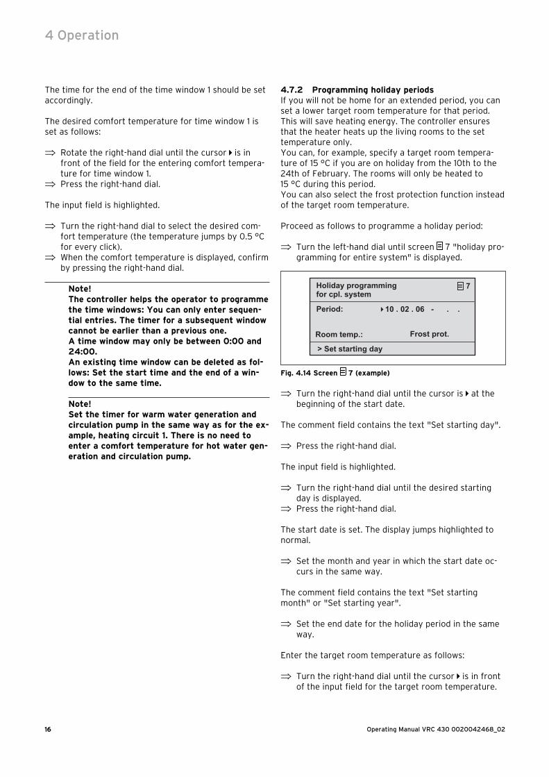
4.7.2 Programming holiday periodsIf you will not be home for an extended period, you can set a lower target room temperature for that period. This will save heating energy. The controller ensures that the heater heats up the living rooms to the set temperature only.You can, for example, specify a target room tempera-ture of 15 °C if you are on holiday from the 10th to the 24th of February. The rooms will only be heated to 15 °C during this period.You can also select the frost protection function instead of the target room temperature.
Proceed as follows to programme a holiday period:
⇒ Turn the left-hand dial until screen 7 "holiday pro-gramming for entire system" is displayed.
> Set starting day
�
Holiday programming 7
Period:
for cpl. system
Room temp.:
10 . 02 . 06 - . .
Frost prot.
Fig. 4.14 Screen 7 (example)
⇒ Turn the right-hand dial until the cursor is at the beginning of the start date.
The comment field contains the text "Set starting day".
⇒ Press the right-hand dial.
The input field is highlighted.
⇒ Turn the right-hand dial until the desired starting day is displayed.
⇒ Press the right-hand dial.
The start date is set. The display jumps highlighted to normal.
⇒ Set the month and year in which the start date oc-curs in the same way.
The comment field contains the text "Set starting month" or "Set starting year".
⇒ Set the end date for the holiday period in the same way.
Enter the target room temperature as follows:
⇒ Turn the right-hand dial until the cursor is in front of the input field for the target room temperature.
4 Operation
16
17Operating Manual VRC 430 0020042468_02
The comment field contains the text "Select target room temperature".
⇒ Press the right-hand dial.
The input field is highlighted.
⇒ Turn the right-hand dial until the desired value is displayed (values from 5 °C to 30 °C in increments of 0.5 °C and frost protection function are possible).
⇒ Press the right-hand dial.
The desired target room temperature or the frost func-tion are set. The display jumps highlighted to normal.
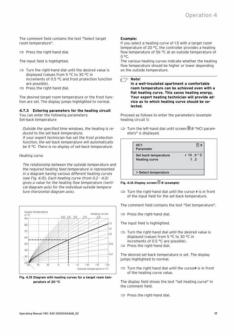
4.7.3 Entering parameters for the heating circuitYou can enter the following parameters:Set-back temperature
Outside the specified time windows, the heating is re-duced to the set-back temperature.If your expert technician has set the frost protection function, the set-back temperature will automatically be 5 °C. There is no display of set-back temperature.
Heating curve
The relationship between the outside temperature and the required heating feed temperature is represented in a diagram having various different heating curves (see Fig. 4.15). Each heating curve (from 0.2 - 4.0) gives a value for the heating flow temperature (verti-cal diagram axis) for the individual outside tempera-ture (horizontal diagram axis).
Fig. 4.15 Diagram with heating curves for a target room tem-
perature of 20 °C
Example:If you select a heating curve of 1.5 with a target room temperature of 20 °C, the controller provides a heating flow temperature of 56 °C at an outside temperature of 0 °C.The various heating curves indicate whether the heating flow temperature should be higher or lower depending on the outside temperature.
h Note!In a well-insulated apartment a comfortable room temperature can be achieved even with a flat heating curve. This saves heating energy.Your expert heating technician will provide ad-vice as to which heating curve should be se-lected.
Proceed as follows to enter the parameters (example heating circuit 1):
⇒ Turn the left-hand dial until screen 8 "HC1 param-eters" is displayed.
> Select temperature
�
HC1 8
Set back temperature
Parameter
Heating curve 15 . 0 ° C
1 . 2
Fig. 4.16 Display screen 8 (example)
⇒ Turn the right-hand dial until the cursor is in front of the input field for the set-back temperature.
The comment field contains the text "Set temperature".
⇒ Press the right-hand dial.
The input field is highlighted.
⇒ Turn the right-hand dial until the desired value is displayed (values from 5 °C to 30 °C in increments of 0.5 °C are possible).
⇒ Press the right-hand dial.
The desired set-back temperature is set. The display jumps highlighted to normal.
⇒ Turn the right-hand dial until the cursor is in front of the heating curve value.
The display field shows the text "set heating curve" in the comment field.
⇒ Press the right-hand dial.
Operation 4
17
Operating Manual VRC 430 0020042468_0218
The input field is highlighted.
⇒ Turn the right-hand dial until the desired value is displayed (values from 0.2 to 4.0 are possible, see Fig. 4.15).
⇒ Press the right-hand dial.
The desired heating curve is set. The display changes from highlighted to normal.
4.7.4 Entering parameters for hot water generationIf the heating unit also heats your hot water, you can enter the set target temperature on the controller.
⇒ Turn the left-hand dial until screen 10 "Hot water parameters" is displayed.
The cursor is located in front of the value for the set target temperature.
⇒ Press the right-hand dial.
The input field is highlighted.
⇒ Turn the right-hand dial until the desired value is displayed (values from 35 °C to 70 °C in increments of 1 °C are possible).
⇒ Press the right-hand dial.
The desired set target temperature is set. The display jumps highlighted to normal.
H Caution!Risk of being scalded by hot water!At the draw-off locations for the hot water there is a danger of scalding at temperatures in excess of 60 °C. Young children and elderly persons can be in danger even at lower temper-atures.Select the target temperature so that nobody is in danger.
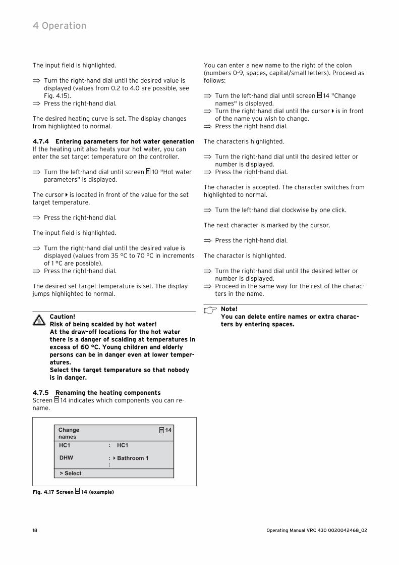
4.7.5 Renaming the heating componentsScreen 14 indicates which components you can re-name.
> Select
Changenames
14
HC1
DHW :
:
�
:
HC1
Bathroom 1
Fig. 4.17 Screen 14 (example)
You can enter a new name to the right of the colon (numbers 0-9, spaces, capital/small letters). Proceed as follows:
⇒ Turn the left-hand dial until screen 14 "Change names" is displayed.
⇒ Turn the right-hand dial until the cursor is in front of the name you wish to change.
⇒ Press the right-hand dial.
The characteris highlighted.
⇒ Turn the right-hand dial until the desired letter or number is displayed.
⇒ Press the right-hand dial.
The character is accepted. The character switches from highlighted to normal.
⇒ Turn the left-hand dial clockwise by one click.
The next character is marked by the cursor.
⇒ Press the right-hand dial.
The character is highlighted.
⇒ Turn the right-hand dial until the desired letter or number is displayed.
⇒ Proceed in the same way for the rest of the charac-ters in the name.
h Note! You can delete entire names or extra charac-ters by entering spaces.
4 Operation
19Operating Manual VRC 430 0020042468_02
5 Status and error messages
Status and error messages are displayed in the second row of the basic data section.
Status messages
– Holiday programme active
Within a specified holiday period the heating is con-trolled according to the temperatures set for that pe-riod.
– Maintenance + telephone number of the expert techni-cian
Indicates that the heating system requires mainte-nance work. The telephone number of your expert technician will also appears if it has been entered into the system.
Error message:
Fault on heating unit.
Draws attention to a fault in the heating unit.
⇒ Contact your expert technician.
The unit is faulty if the screen remains dark or you are unable to make any changes using the dial.
⇒ Contact your expert technician.
Status and error messages 5

For the heating engineer:
Installation Manual
VRC 430
VRC 430Weather compensator
Contents
1 Notes on the documentation .........................21.1 Storing of the documents .....................................21.2 Symbols used ...........................................................21.3 Applicability of the manual ...................................2
2 Description of the appliance .........................32.1 Identification plate ..................................................32.2 CE label ......................................................................32.3 Intended use .............................................................4
3 Safety instructions and regulations ............43.1 Safety information ..................................................43.2 Regulations ...............................................................4
4 Assembly .........................................................54.1 Scope of delivery ....................................................54.2 Accessories ...............................................................54.3 Location .....................................................................54.4 Fitting the controller in the heating unit ..........54.5 Wall mounting the controller ...............................64.6 Fitting the external sensor ...................................6
5 Installation ....................................................... 75.1 Electrical installation of the controller
when mounted on the wall ...................................75.2 Electrical installation of theexternal
sensor VRC 693 .......................................................85.3 Electrical installation of the external
sensor VRC 9535 ....................................................8
6 Initial start-up .................................................96.1 Installation assistant ..............................................96.2 Expert technician level ..........................................96.3 Restoring default parameters ........................... 106.4 Grout drying function ...........................................136.5 Handing over the appliance to the owner .......13
7 Service, warranty ..........................................137.1 Vaillant service .......................................................137.2 Vaillant warranty....................................................13
8 Recycling and disposal ................................. 14
9 Technical data ............................................... 14
Glossary .....................................................................15
Installation Instructions VRC 430 0020042468_022
1 Notes on the documentation
The following information is intended to help you work through the documentation. Additional documents apply in conjunction with this installation manual.We accept no liability for any damage caused by failure to observe these instructions.
Other applicable documents– The operating instructions for the Vaillant controller
VRC 430 (Section 1 of this document)– The operating and installation instructions for your
heating unit– All instructions for accessory components
1.1 Storing of the documentsPlease pass on this installation manual and all other valid documents and auxiliary equipment to the owner of the unit. This person is responsible keeping these documents safe. The documents must be made available if required.
1.2 Symbols usedPlease observe the safety instructions in this manual when installing the unit!
e Danger!Danger of death by electrocution!
d Danger!Immediate risk of serious injury or death!
H Caution!Danger of burning and scalding!
a Caution!Potentially dangerous situation for the product and environment!
h Note!Useful information and instructions.
⇒ Symbol indicating a required task
1.3 Applicability of the manualThese installation instructions apply exclusively to appli-ances with the following article numbers:
0020028520 VRC 430
The part number of your unit can be obtained from the identification plate.
1 Notes on the documentation
3Installation Instructions VRC430 0020042468_02
2 Description of the appliance
The VRC 430 is a weather compensator designed for heating and hot water generation in conjunction with a Vaillant boiler (eBUS-capable).The VRC 430 can also be used to control the following accessory components:
– Circulation pump for hot water generation in conjunc-tion with a multi-functional module 2 of 7
– Conventional domestic hot water cylinder– Vaillant layer hot water storage tank actoSTOR– Second heating circuit using the Vaillant Mixer
Module VR 61– Solar unit using the Vaillant Solar Module VR 68
On the VRC 430 data is exchanged and power supplied via an eBUS interface.
The VRC 430 can be operated with the Vaillant remote control VR 81.
The VRT 430 is equipped for operation with the Vaillant diagnosis software vrDIALOG 810/2 and with the Vaillant Internet Communication System vrnetDIALOG, i.e. for remote diagnosis and remote set-ting.
230 V~
1
45
2 3
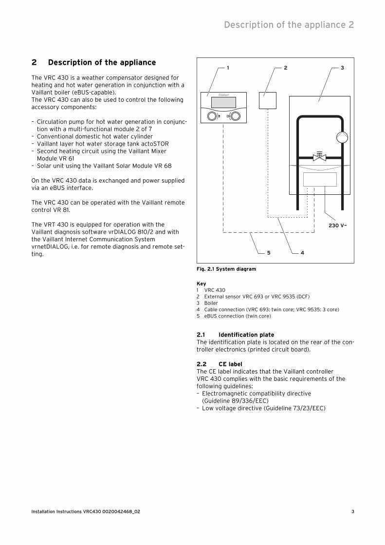
Fig. 2.1 System diagram
Key1 VRC 4302 External sensor VRC 693 or VRC 9535 (DCF)3 Boiler4 Cable connection (VRC 693: twin core; VRC 9535: 3 core)5 eBUS connection (twin core)
2.1 Identification plateThe identification plate is located on the rear of the con-troller electronics (printed circuit board).
2.2 CE labelThe CE label indicates that the Vaillant controller VRC 430 complies with the basic requirements of the following guidelines:– Electromagnetic compatibility directive
(Guideline 89/336/EEC)– Low voltage directive (Guideline 73/23/EEC)
Description of the appliance 2

Installation Instructions VRC 430 0020042468_024
2.3 Intended useThe VRC 430 weather compensator is a state-of-the-art appliance constructed in accordance with recognised safety regulations.However, damage and property may occur if the unit is used improperly or for a purpose other than the intend-ed purpose.The VRC 430 controller is designed for use as a weather compensator and timer-based controller with or without hot water generation/ circulation pump in conjunction with a Vaillant heating unit with eBUS interface.Operation with the following accessories is permitted:
– Circulation pump for hot water generation in conjunc-tion with a multi-functional module 2 of 7
– Conventional domestic hot water cylinder– Vaillant layer hot water storage tank actoSTOR– Second heating circuit using the Vaillant Mixer
Module VR 61– Solar unit using the Vaillant Solar Module VR 68– VR 81 remote control device
Any other or extended use is considered to be use other than intended. The manufacturer or supplier is not liable for any resulting damage. The owner alone bears any risk.Intended use also includes observing the operating and installation instructions and all other applicable docu-ments.
3 Safety instructions and regulations
The controller must be installed by a suitably qualified expert technician, who is responsible for observing ex-isting standards and regulations. We accept no liability for any damage caused by failure to observe these in-structions.
3.1 Safety information
e Danger!Live connections!There is a danger to life from electrocution when working on the electronics box of the boil-er.Switch off the power supply to the electronics box of the heating unit and secure against re-connection before carrying out any work.Only open the electronics box if the heating unit is disconnected from the power source.
3.2 RegulationsDuring the electrical installation, observe the VDE and EVU regulations.
Use standard commercial cables for wiring.Minimum cross-section for sensor and Bus lines: 0.75 mm2
Do not exceed the following maximum wire lengths:– Sensor lines 50 m– eBUS lines 300 m
If sensor and eBUS lines run parallel with 230 V cables for more than 10 m, they must be laid separately.Do not use free terminals of the appliances as support terminals for other wiring.
The controller may only be installed in dry rooms.
All wiring must be in accordance with Building Regula-tions Part P and BS 7671 (IEE Wiring Regulations), and must be carried out by a suitably qualified person.
2 Description of the appliance3 Safety instructions and regulations
5Installation Instructions VRC430 0020042468_02
4 Assembly
The VRC 430 can either be integrated in the heating unit or mounted separately in the living area on a wall. When mounting on the wall, the connection to the heat-ing unit is via a twin-core eBUS line.The VRC 430 is supplied with one of the following exter-nal sensors:– VRC 693
connection is via a twin core cable to the heating unit– VRC 9535 (DCF)
connection is via a 3-core cable to the heating unit
4.1 Scope of deliveryUsing Table 4.1, check the scope of delivery
Pos. Number Component
1 1 Controller VRC 430
2 1External sensor VRC 693 orExternal sensor VRC 9535 (DCF)
3 1 Fixing material
4 1 6-pole edge connector
5 1Operating and Installation Manual
Table 4.1 Scope of supply VRC 430
4.2 AccessoriesThe following accessories can be used to extend con-troller functionalities:
2 of 7 multi-functional modulesThe multi-function module VR 2 of 7 can be used by the VRC 430 to control a circulation pump.
VR 61 mixer moduleThe mixer-module VR 61 extends the VRC 430 function-ality to include a twin-circuit controller.
Solar module VR 68The solar module VR 68 can be used by the VRC 430 to control a solar installation.
VR 81 remote control unitThe remote control VR 81 is recommended if the VRC 430 is fitted in the heating unit, or if the second heating circuit is to be controlled decentrally.The remote control VR 81 can be used to set the follow-ing parameters:– Operating mode– Target room temperature
Symbols are displayed indicating maintenance and error messages.Data interchange is via eBus line.
h Note!If accessory components are connected to the VRC 430, the instructions for these compo-nents must also be observed.
4.3 LocationThe controller should only be installed in dry rooms.
If the controller is mounted on the wall, it should be fit-ted in such a way that the room temperature is meas-ured properly; e.g. on an internal wall of the main living room, at a height of approx. 1.5 m
If the thermostat function is activated, advise the opera-tor that all the radiator valves must be fully open in the room where the controller is mounted.
See Chapter 4.6 for information on locating the outdoor sensor.
4.4 Fitting the controller in the heating unit
e Danger!Live connections!There is a danger to life from electrocution when working on the electronics box of the boil-er.Switch off the power supply to the electronics box of the heating unit and secure against re-connection before carrying out any work.Only open the electronics box if the heating unit is disconnected from the power source.
Proceed as follows:
⇒ Switch the boiler off.⇒ Turn off the power supply to the heating unit and
secure the power supply against re-connection.⇒ Remove the front screen from the heating unit.⇒ Carefully press the controller (without wall plinth,
see Fig. 4.1) with the pin rail into the plug connector on the heating unit.
⇒ Now fit the external sensor (see Chapter 4.6), if not already done.
⇒ Carry out the electrical installation of the external sensor as described in Chapter 5.2 or 5.3.
⇒ Re-connect the power supply to the heating unit.⇒ Switch the heating unit on again.
Assembly 4
Installation Instructions VRC 430 0020042468_026
4.5 Wall mounting the controller
1
2
5
4 3
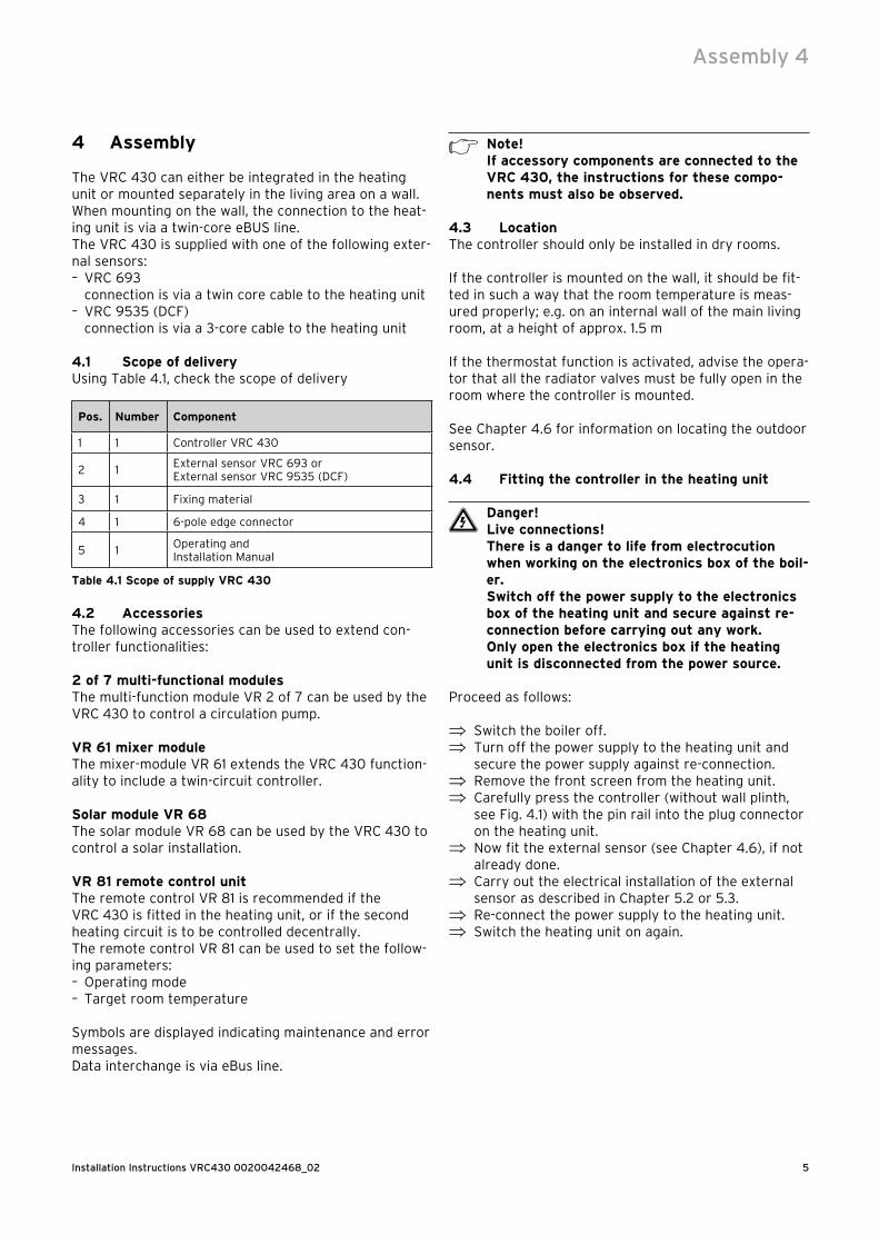
Fig. 4.1 Fitting the external sensor 430
Key1 Controller VRC 4302 Wall plinth3 Installation opening4 Openings for cable duct5 Terminals for eBUS line and plug connection for pin rail
Proceed as follows:
⇒Pull the room thermostat (1) off the wall plinth (2). This can be done by pushing a screwdriver into the two retaining straps (see Fig. 4.1 arrows).
⇒ Mark the position on the wall. Take the eBUS line route into account when doing so.
⇒ Drill two holes 6 mm in diameter to match the fixing apertures (3).
⇒ Insert the rawl plugs supplied.⇒ Insert the eBUS cable through one of the cable con-
duits (4).⇒ Use the screws supplied to fix the wall socket .⇒ Electrical installation is described in Chapter 5.1.⇒ Carefully press the controller onto the wall socket
until it clicks into position. The pin rail on the back of the controller must fit into the plug connector (5) on the wall socket.
4.6 Fitting the external sensorThe mounting location of the external sensor should meet the following conditions:- not fully protected from wind- no particularly draughty- no direct sunlight- no influence from heat sources- N or NW facing facade
On buildings with up to 3 floors, the external sensor should be two-thirds up the building; on buildings with more than 3 floors, install it between the 2nd and 3rd floors.
a Caution!Dampness in the wall and in the unit!Incorrect installation can result in damage to the unit and/or the wall of the building.Observe the cable routing described and the correct installation position of the external sensor.
h Note!Installation is the same for both external sen-sors, with the following exceptions:– the VRC 693 requires a two-core
connection cable– the VRC 9535 requires a three-core
connection cable
1
2
3
43
5
4
Fig. 4.2 Fitting the external sensor VRC 693
Key1 Casing cover2 Wall plinth3 Cap nut for cable conduit4 Connection cable with drip loop5 Installation opening
4 Assembly
7Installation Instructions VRC430 0020042468_02
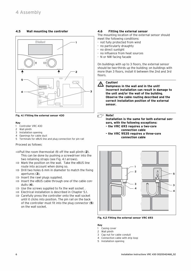
Fig. 4.3 Fitting the external sensor VRC 9535
Key1 Casing cover2 Wall plinth3 Cap nut for cable conduit4 Connection cable with drip loop5 Installation opening
Proceed as follows:
⇒ Mark the position on the wall. Observe the cable routing for the external sensor.
⇒ Route the connection cable (4) with a slight incline to the outside and with a drip loop.
⇒ Remove the cover (1) from the external sensor cas-ing.
⇒ Drill two holes 6 mm in diameter to match the fixing apertures (5).
⇒ Insert the rawl plugs supplied.⇒ Fix the wall socket (2) to the wall with 2 screws. The
cable entry must point downwards.⇒ Release the cap nut (3) slightly and push the con-
nection cable through the cable entry from below.⇒ The electrical installation is described in Chapter 5.2
for the VRC 693, and in Chapter 5.3 for the VRC 9535 .
⇒ Re-tighten the cap nut (3). The packing in the cable entry adapts to the diameter of the cable used (Cable diameter: 4.5 to 10 mm).
⇒ Carefully push the cover for the enclosure onto the wall socket until it clicks in position. Do not forget the seal between the wall socket and the cover for the enclosure.
5 Installation
e Danger!Live connections!
There is a danger to life from electrocution when working on the electronics box of the boil-er.
Switch off the power supply to the electronics box of the heating unit and secure against re-connection before carrying out any work.Only open the electronics box if the heating unit is disconnected from the power source.
If the controller is installed in the heating unit, the elec-trical connection is made by the contact between the pin rail of the controller and the corresponding plug connection in the heating unit.
5.1 Electrical installation of the controller when mounted on the wall
The power supply to the heating unit is switched off and secured against re-connection.
1
2
Fig. 5.1 Electrical connection with VRC 430
Key1 Terminal rail VRC 4302 Heating unit terminal rail
Assembly 4Installation 5
Installation Instructions VRC 430 0020042468_028
h Note!The bridge between the terminals 3 and 4 (see Fig. 5.1) should not be removed.When connecting the eBUS cable there is no need to make sure the polarity is correct. Com-munication is not adversely impacted if the two connections are swapped over.
Proceed as follows:
⇒ Connect the eBUS cable to the VRC 430 terminal rail.
⇒ Connect the eBUS cable to the terminal rail on the heating unit.
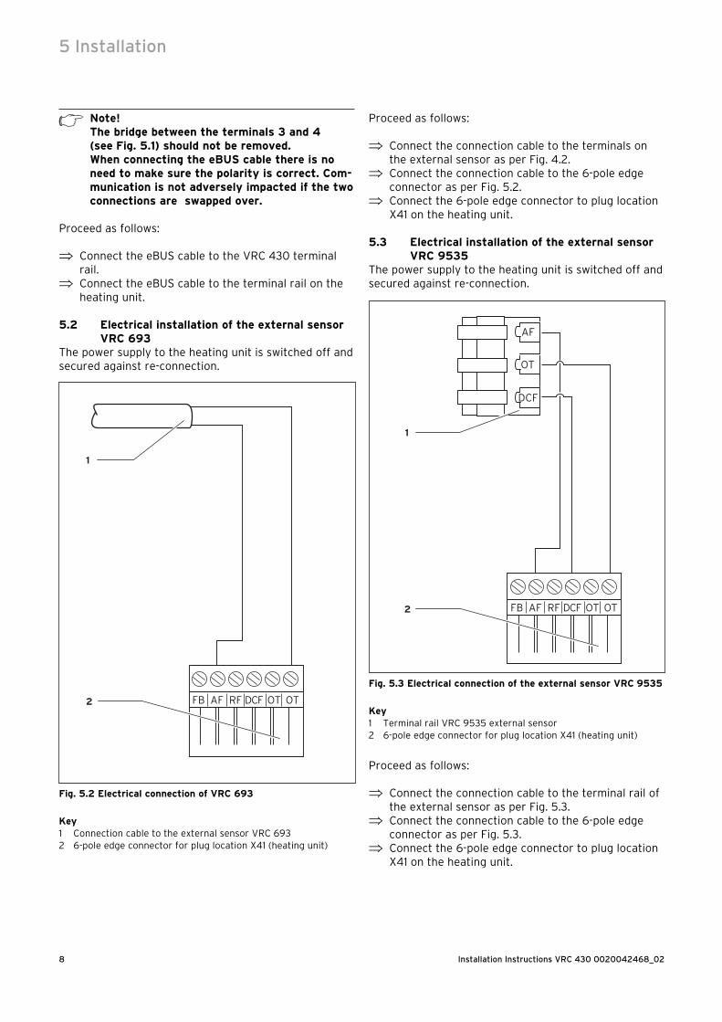
5.2 Electrical installation of the external sensor VRC 693
The power supply to the heating unit is switched off and secured against re-connection.
1
2
Fig. 5.2 Electrical connection of VRC 693
Key1 Connection cable to the external sensor VRC 6932 6-pole edge connector for plug location X41 (heating unit)
Proceed as follows:
⇒ Connect the connection cable to the terminals on the external sensor as per Fig. 4.2.
⇒ Connect the connection cable to the 6-pole edge connector as per Fig. 5.2.
⇒ Connect the 6-pole edge connector to plug location X41 on the heating unit.
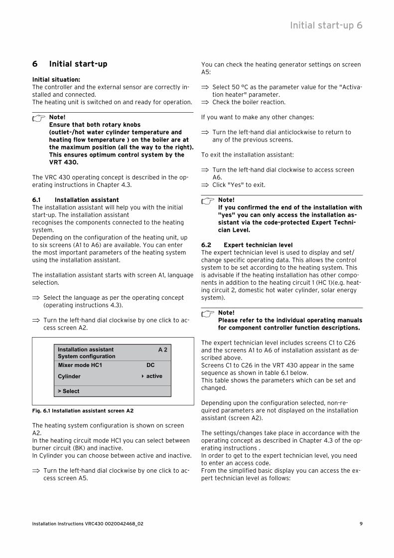
5.3 Electrical installation of the external sensor VRC 9535
The power supply to the heating unit is switched off and secured against re-connection.
1
2
Fig. 5.3 Electrical connection of the external sensor VRC 9535
Key1 Terminal rail VRC 9535 external sensor2 6-pole edge connector for plug location X41 (heating unit)
Proceed as follows:
⇒ Connect the connection cable to the terminal rail of the external sensor as per Fig. 5.3.
⇒ Connect the connection cable to the 6-pole edge connector as per Fig. 5.3.
⇒ Connect the 6-pole edge connector to plug location X41 on the heating unit.
5 Installation
9Installation Instructions VRC430 0020042468_02
6 Initial start-up
Initial situation:The controller and the external sensor are correctly in-stalled and connected.The heating unit is switched on and ready for operation.
h Note!Ensure that both rotary knobs(outlet-/hot water cylinder temperature and heating flow temperature ) on the boiler are at the maximum position (all the way to the right). This ensures optimum control system by the VRT 430.
The VRC 430 operating concept is described in the op-erating instructions in Chapter 4.3.
6.1 Installation assistantThe installation assistant will help you with the initial start-up. The installation assistantrecognises the components connected to the heating system.Depending on the configuration of the heating unit, up to six screens (A1 to A6) are available. You can enter the most important parameters of the heating system using the installation assistant.
The installation assistant starts with screen A1, language selection.
⇒ Select the language as per the operating concept (operating instructions 4.3).
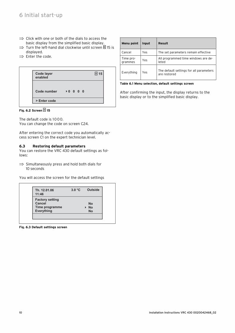
⇒ Turn the left-hand dial clockwise by one click to ac-cess screen A2.
Installation assistantSystem configurationMixer mode HC1
> Select
Cylinder active
DC
�
A 2
Fig. 6.1 Installation assistant screen A2
The heating system configuration is shown on screen A2.In the heating circuit mode HC1 you can select between burner circuit (BK) and inactive.In Cylinder you can choose between active and inactive.
⇒ Turn the left-hand dial clockwise by one click to ac-cess screen A5.
You can check the heating generator settings on screen A5:
⇒ Select 50 °C as the parameter value for the "Activa-tion heater" parameter.
⇒ Check the boiler reaction.
If you want to make any other changes:
⇒ Turn the left-hand dial anticlockwise to return to any of the previous screens.
To exit the installation assistant:
⇒ Turn the left-hand dial clockwise to access screen A6.
⇒ Click "Yes" to exit.
h Note! If you confirmed the end of the installation with "yes" you can only access the installation as-sistant via the code-protected Expert Techni-cian Level.
6.2 Expert technician levelThe expert technician level is used to display and set/change specific operating data. This allows the control system to be set according to the heating system. This is advisable if the heating installation has other compo-nents in addition to the heating circuit 1 (HC 1)(e.g. heat-ing circuit 2, domestic hot water cylinder, solar energy system).
h Note!Please refer to the individual operating manuals for component controller function descriptions.
The expert technician level includes screens C1 to C26 and the screens A1 to A6 of installation assistant as de-scribed above.Screens C1 to C26 in the VRT 430 appear in the same sequence as shown in table 6.1 below.This table shows the parameters which can be set and changed.
Depending upon the configuration selected, non-re-quired parameters are not displayed on the installation assistant (screen A2).
The settings/changes take place in accordance with the operating concept as described in Chapter 4.3 of the op-erating instructions .In order to get to the expert technician level, you need to enter an access code.From the simplified basic display you can access the ex-pert technician level as follows:
Initial start-up 6
Installation Instructions VRC 430 0020042468_0210
⇒ Click with one or both of the dials to access the basic display from the simplified basic display.
⇒ Turn the left-hand dial clockwise until screen 15 is displayed.
⇒ Enter the code.
> Enter code
�
Code layer 15enabled
Code number 0 0 0 0
Fig. 6.2 Screen 15
The default code is 1 0 0 0.You can change the code on screen C24.
After entering the correct code you automatically ac-cess screen C1 on the expert technician level.
6.3 Restoring default parametersYou can restore the VRC 430 default settings as fol-lows:
⇒ Simultaneously press and hold both dials for 10 seconds
You will access the screen for the default settings
Sommer/Winterzeit-Umstellung
Cancel Factory setting
Time programme Everything
Th. 12.01.0611:46
3.0 °C Outside
NoNo
�
No
Fig. 6.3 Default settings screen
Menu point Input Result
Cancel Yes The set parameters remain effective
Time pro-grammes
YesAll programmed time windows are de-leted
Everything YesThe default settings for all parameters are restored
Table 6.1 Menu selection, default settings screen
After confirming the input, the display returns to the basic display or to the simplified basic display.
6 Initial start-up
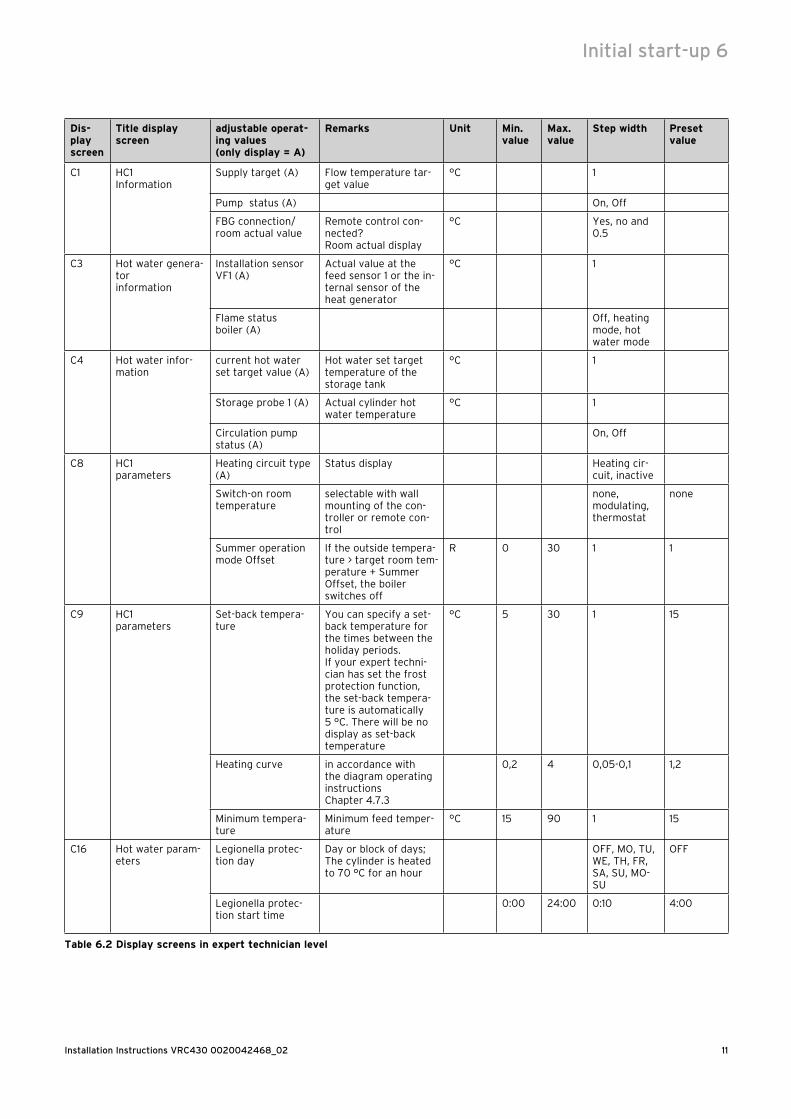
11Installation Instructions VRC430 0020042468_02
Dis-play screen
Title display screen
adjustable operat-ing values (only display = A)
Remarks Unit Min.value
Max.value
Step width Preset value
C1 HC1Information
Supply target (A) Flow temperature tar-get value
°C 1
Pump status (A) On, Off
FBG connection/room actual value
Remote control con-nected?Room actual display
°C Yes, no and 0.5
C3 Hot water genera-torinformation
Installation sensor VF1 (A)
Actual value at the feed sensor 1 or the in-ternal sensor of the heat generator
°C 1
Flame status boiler (A)
Off, heating mode, hot water mode
C4 Hot water infor-mation
current hot water set target value (A)
Hot water set target temperature of the storage tank
°C 1
Storage probe 1 (A) Actual cylinder hot water temperature
°C 1
Circulation pump status (A)
On, Off
C8 HC1parameters
Heating circuit type (A)
Status display Heating cir-cuit, inactive
Switch-on room temperature
selectable with wall mounting of the con-troller or remote con-trol
none, modulating, thermostat
none
Summer operation mode Offset
If the outside tempera-ture > target room tem-perature + Summer Offset, the boiler switches off
R 0 30 1 1
C9 HC1parameters
Set-back tempera-ture
You can specify a set-back temperature for the times between the holiday periods.If your expert techni-cian has set the frost protection function, the set-back tempera-ture is automatically 5 °C. There will be no display as set-back temperature
°C 5 30 1 15
Heating curve in accordance with the diagram operating instructions Chapter 4.7.3
0,2 4 0,05-0,1 1,2
Minimum tempera-ture
Minimum feed temper-ature
°C 15 90 1 15
C16 Hot water param-eters
Legionella protec-tion day
Day or block of days; The cylinder is heated to 70 °C for an hour
OFF, MO, TU, WE, TH, FR, SA, SU, MO-SU
OFF
Legionella protec-tion start time
0:00 24:00 0:10 4:00
Table 6.2 Display screens in expert technician level
Initial start-up 6
Installation Instructions VRC 430 0020042468_0212
Dis-play screen
Title display screen
adjustable operat-ing values (only display = A)
Remarks Unit Min.value
Max.value
Step width Preset value
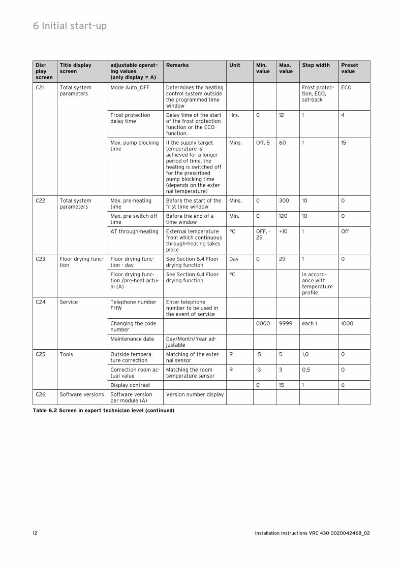
C21 Total systemparameters
Mode Auto_OFF Determines the heating control system outside the programmed time window
Frost protec-tion, ECO, set-back
ECO
Frost protection delay time
Delay time of the start of the frost protection function or the ECO function.
Hrs. 0 12 1 4
Max. pump blocking time
If the supply target temperature is achieved for a longer period of time, the heating is switched off for the prescribed pump-blocking time (depends on the exter-nal temperature)
Mins. Off, 5 60 1 15
C22 Total systemparameters
Max. pre-heating time
Before the start of the first time window
Mins. 0 300 10 0
Max. pre-switch off time
Before the end of a time window
Min. 0 120 10 0
AT through-heating External temperature from which continuous through-heating takes place
°C OFF, -25
+10 1 Off
C23 Floor drying func-tion
Floor drying func-tion - day
See Section 6.4 Floor drying function
Day 0 29 1 0
Floor drying func-tion /pre-heat actu-al (A)
See Section 6.4 Floor drying function
°C in accord-ance with temperature profile
C24 Service Telephone number FHW
Enter telephone number to be used in the event of service
Changing the code number
0000 9999 each 1 1000
Maintenance date Day/Month/Year ad-justable
C25 Tools Outside tempera-ture correction
Matching of the exter-nal sensor
R -5 5 1,0 0
Correction room ac-tual value
Matching the room temperature sensor
R -3 3 0,5 0
Display contrast 0 15 1 6
C26 Software versions Software version per module (A)
Version number display
Table 6.2 Screen in expert technician level (continued)
6 Initial start-up
13Installation Instructions VRC430 0020042468_02
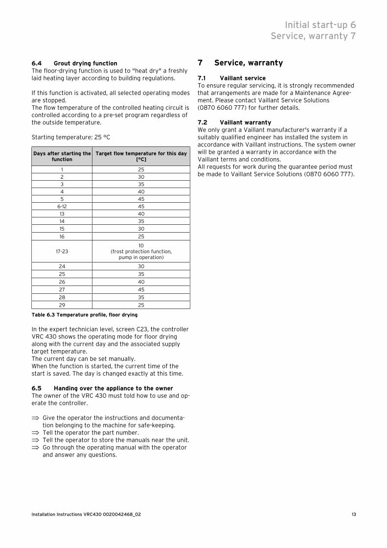
6.4 Grout drying functionThe floor-drying function is used to "heat dry" a freshly laid heating layer according to building regulations.
If this function is activated, all selected operating modes are stopped.The flow temperature of the controlled heating circuit is controlled according to a pre-set program regardless of the outside temperature.
Starting temperature: 25 °C
Days after starting the function
Target flow temperature for this day[°C]
1 25
2 30
3 35
4 40
5 45
6-12 45
13 40
14 35
15 30
16 25
17-2310
(frost protection function,pump in operation)
24 30
25 35
26 40
27 45
28 35
29 25
Table 6.3 Temperature profile, floor drying
In the expert technician level, screen C23, the controller VRC 430 shows the operating mode for floor drying along with the current day and the associated supply target temperature.The current day can be set manually.When the function is started, the current time of the start is saved. The day is changed exactly at this time.
6.5 Handing over the appliance to the ownerThe owner of the VRC 430 must told how to use and op-erate the controller.
⇒ Give the operator the instructions and documenta-tion belonging to the machine for safe-keeping.
⇒ Tell the operator the part number.⇒ Tell the operator to store the manuals near the unit.⇒ Go through the operating manual with the operator
and answer any questions.
7 Service, warranty
7.1 Vaillant serviceTo ensure regular servicing, it is strongly recommended that arrangements are made for a Maintenance Agree-ment. Please contact Vaillant Service Solutions(0870 6060 777) for further details.
7.2 Vaillant warrantyWe only grant a Vaillant manufacturer's warranty if a suitably qualified engineer has installed the system in accordance with Vaillant instructions. The system owner will be granted a warranty in accordance with the Vaillant terms and conditions.All requests for work during the guarantee period must be made to Vaillant Service Solutions (0870 6060 777).
Initial start-up 6Service, warranty 7
Installation Instructions VRC 430 0020042468_0214
8 Recycling and disposal
Both your VRC 430 and its packaging are primarily made of recyclable raw materials.
ApplianceNeither the VRC 430 nor any of its accessories may be disposed of in the household waste. Make sure the old appliance and any accessories are disposed of properly.
PackagingDisposal of the transport packaging is undertaken by the expert technician who installed the unit.
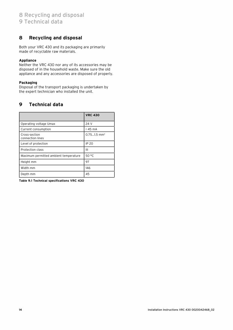
9 Technical data
VRC 430
Operating voltage Umax 24 V
Current consumption < 45 mA
Cross-sectionconnection lines
0.75…1.5 mm2
Level of protection IP 20
Protection class III
Maximum permitted ambient temperature 50 °C
Height mm 97
Width mm 146
Depth mm 45
Table 9.1 Technical specifications VRC 430
8 Recycling and disposal9 Technical data
14
15Installation Instructions VRC430 0020042468_02
Glossary
Set-back temperatureThe set-back temperature is the temperature to which your heating lowers the internal temperature to outside the programmed time windows.
Auto_Off (expert technician level)The "Mode_Auto_Off" menu item in screen C21, "Overall system parameters", is used to determine how the con-troller behaves when the timer-control is off (i.e. be-tween the "time windows"). The options are Frost pro-tection, ECO and set-back.– Frost protection
In the times when no time windows are programmed, the boiler is switched off. The frost protection func-tion (see location) is active.
– ECOIn the times when no time windows are programmed, the boiler is switched off. The external temperature is monitored. If the external temperature falls below 3 °C, the target room value reverts to the set-back temperature (minimum 5 °C). This target room value is used as a basis. A frost protection delay time (see location) will affect the start time here. If the external temperature rises above 4 °C, the external tempera-ture continues to be monitored, the boiler is switched off.
– Set-backIn the times when no time window is programmed, the room target temperature reverts to the set-back tem-perature (minimum 5 °C). This target room value is used as a basis.
Operator levelThis is used to display and set/change basic parameters. The parameters can be set/changed by an unskilled op-erator and during normal operation. The heating system is continuously matched to the requirements of the user by corresponding adjustment of the fundamental pa-rameters.
Operating level for the expert technicianIt serves to display and to set/change specific parame-ters. This level is reserved for the expert technician and is therefore protected by an access code.
Operating modeOperating modes "Auto" (Automatic), "Manual" and "OFF" are available. You can specify the way in which your room heating and water heating are controlled using the operating modes (see operating instructions Section 4.3.2, Table 4.2).
Frost protection functionThe frost protection system protects your heating sys-tem and your apartment from frost damage. It remains active in the operating mode "OFF".
The frost protection function monitors the external tem-perature. If the outside temperature drops below 3 °C, the heating pump switches on for 10 minutes and then off for 10 to 60 min (depends on the outside tempera-ture). If the heating flow temperature is below 13 °C, the burner switches on and controls the room temperature to within 5 °C of the target room temperature. If the ex-ternal temperature rises above 4 °C, the external tem-perature continues to be monitored , the heating pump and burner are switched off.If the outside temperature drops below -20 °C, the burner is switched on and controls the rooms tempera-ture to within 5 °C of the target room temperature.
Frost protection delay timeBy setting the frost protection delay time (expert tech-nician level), you can delay the heating control function, which is usually triggered by the frost-protection func-tion (when the outside temperature is 3 °C ), for a speci-fied time period (1 - 12 hours).The frost protection delay setting also works in the "ECO" function in the "Auto_Off" mode (see location).The frost-protection delay time starts when the outside temperature drops below 3 °C.
Heating circuit (HC1)HC1 indicates heating circuit 1. This refers to your heat-ing system. You can re-name HC1 to something else, if you wish (see operating instructions Section 4.7.5).
Heating curveThe heating curve represents the relationship between external temperature and the flowtemperature. By se-lecting a heating curve, you can control the flow tem-perature of your heating system and therefore also the internal temperature.This option allows to controller, in conjunction with the room switch-on function (see relevant section for de-tails), to adjust to the apartment and heating system.Fig. G.1 shows the possible heating curves for a target room temperature of 20 °C.If, for example, heating curve 1.5 is selected, a flow tem-perature of 56 °C is maintained at an external tempera-ture of 0 °C.
AppendixGlossary

Installation Instructions VRC 430 0020042468_0216
Fig. G.1 Diagram with heating curves for a target room temper-
ature of 20 °C
Axis a
20
22
18
Feed temperaturein ºC
Outside temperature in ºC
Fig. G.2 Parallel offsetting the heating curve
If you select heating curve 1.5 with a room target tem-perature of 22 °C rather than 20 °C, the heating curve is displaced as shown in Fig. G.2. The heating curve is displaced in parallel along the 45° axis according to the value of the room target temperature. This means, therefore, if the external temperature is 0 °C, the con-trol system provides a flow temperature of 67 °C.
Heating flow temperatureYour boiler heats water which is pumped through your heating system. The temperature of this hot water as it leaves the boiler is referred to as the flow temperature.
Internal temperatureThe internal temperature or room temperature is the actual current temperature in your apartment.
ParametersParameters are the properties of your heating system.You can influence these properties by altering the value of a parameter, e.g. changing the "set-back tempera-ture" parameter from 15 °C to 12 °C.
Room switch-on control (expert technician level)In the screen C8 "HC1 Parameter", in the menu point "Room control" you can decide whether to use the tem-perature sensor fitted in the VRC 430 or in the remote control unit. To do this the VRC 430 must be wall-mounted and the remote control unit VR 81 must be connected.The following entries are possible in the menu point "Room switch-on control":– None
The temperature sensor is not used for control sys-tem.
– SwitchingThe in-built temperature sensor measures the current room temperature in the reference room. This value is compared with the room target temperature and, if there is a difference, the heating flow temperature is adjusted accordingly.
– ThermostatThe built-in temperature sensor measures the current room temperature in the reference room. If the meas-ured value is lower than the room target temperature, the heating flow temperature is increased; if the value is higher than the room target temperature, the boiler is switched off.
The use of the room switching, in combination with careful selection of the heating curve, leads to optimum control system of the heating system.
Target room temperatureThe target room temperature is the temperature that you would like in your apartment and which is specified in your controller. Your boiler continues to provide heat until the internal temperature is equal to the target room temperature.When entering the time programmes, the target room temperature is also referred to as the "comfort temper-ature".
Target valuesTarget values are the desired values which you specify to the controller. e. g. the target room temperature or the target temperature for the hot water preparation.
AppendixGlossary
17Installation Instructions VRC430 0020042468_02
Summer/Winter changeoverIn the display screen 1 "Basic Data" in the menu point "Mode selection" you can determine whether the changeover from summer to winter should take place automatically(Selection: Auto).The default setting is switches off automatic changeo-ver (Selection: Off).If the VRC 430 is equipped with the external sensor VRC 9535 which receives the DCF77 time signal, sum-mer/winter changeover takes place automatically; in this case there is no way to switch off the automatic changeover option (Selection: Off).
Flow temperatureSee Heating flow temperature.
Hot water generationYour boiler heats the water in the domestic hot water cylinder to the selected target temperature. If the tem-perature in the domestic hot water cylinder falls by spe-cific value, the water is heated up again to the target temperature. Time windows can be programmed for hot water generation.
Time windowYou can specify three time windows per day for heating, hot water generation and the circulation pump (see op-erating instructions Section 4.7.1).Every heating time window is assigned a target value.The hot water target value is used as a basis for gener-ating hot water (screen 10 "Hot water parameters").The time windows specify the time for the circulation pump.In automatic mode the system is controlled as per the specified values in the time windows.
Circulation pumpWhen you turn on the hot water tap it can take a few moments - depending upon the length of the pipe - be-fore hot water comes out. A circulation pump pumps hot water through the pipes in the hot water circuit. This ensures that hot water is immediately available when you turn on the tap. Time windows can be programmed for the circulation pump.
AppendixGlossary


00
20
04
24
68
_02
GB
0
92
00
8