Embed Size (px)
Citation preview
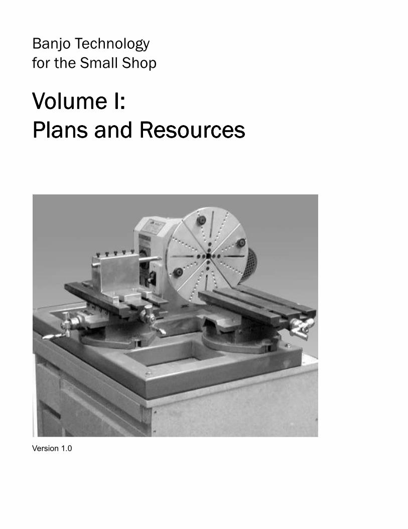
Banjo Technology
for the Small Shop
Volume I:Volume I:Volume I:Volume I:
Plans and ResourcesPlans and ResourcesPlans and ResourcesPlans and Resources
Version 1.0
Table of Contents
Introduction- - - - - - - - - - - - - - - - - - - - - - - - - - - - - - - - - - - - - - - - - - - - - - - - - - - - - - - - - 1The Base - - - - - - - - - - - - - - - - - - - - - - - - - - - - - - - - - - - - - - - - - - - - - - - - - - - - - - - - - - - 2
Typical Mounting for Lathe Head- - - - - - - - - - - - - - - - - - - - - - - - - - - - - - - - - - - - - - - - 4Tool Holders - - - - - - - - - - - - - - - - - - - - - - - - - - - - - - - - - - - - - - - - - - - - - - - - - - - - - - - - 5
Square-stock Tool Holder - - - - - - - - - - - - - - - - - - - - - - - - - - - - - - - - - - - - - - - - - - 5Boring Bar Tool Holder - - - - - - - - - - - - - - - - - - - - - - - - - - - - - - - - - - - - - - - - - - - - 6
Indexing Jig - - - - - - - - - - - - - - - - - - - - - - - - - - - - - - - - - - - - - - - - - - - - - - - - - - - - - - - - - 7
Striker Pin Assembly - - - - - - - - - - - - - - - - - - - - - - - - - - - - - - - - - - - - - - - - - - - - - - 7
Indexing Pin Assembly- - - - - - - - - - - - - - - - - - - - - - - - - - - - - - - - - - - - - - - - - - - - - 8Appendix - - - - - - - - - - - - - - - - - - - - - - - - - - - - - - - - - - - - - - - - - - - - - - - - - - - - - - - - - A-1
List of Figures
Figure 1 - Steel Base Dimensions. . . . . . . . . . . . . . . . . . . . . . . . . . . . . . . . . . . . . . . . . . . 2
Figure 2 - Location of Cross Slide Mounting Holes . . . . . . . . . . . . . . . . . . . . . . . . . . . . . 3Figure 3 - Photograph of Bolts Used to Secure Cross Slides to Base . . . . . . . . . . . . . . 3
Figure 4 - Typical Lathe Head Mounting Ring . . . . . . . . . . . . . . . . . . . . . . . . . . . . . . . . . 4Figure 5 - Lathe Head, Bottom View . . . . . . . . . . . . . . . . . . . . . . . . . . . . . . . . . . . . . . . . . 4Figure 6 - Top and Side View of Square-stock Tool Holder . . . . . . . . . . . . . . . . . . . . . . . 5Figure 7 - Front View of the Square-stock Tool Holder . . . . . . . . . . . . . . . . . . . . . . . . . . 5
Figure 8 - Boring Bar Tool Holder . . . . . . . . . . . . . . . . . . . . . . . . . . . . . . . . . . . . . . . . . . . 6Figure 9 - Indexing Jig, Part A . . . . . . . . . . . . . . . . . . . . . . . . . . . . . . . . . . . . . . . . . . . . . . 7
Figure 10 - Indexing Jig, Part B . . . . . . . . . . . . . . . . . . . . . . . . . . . . . . . . . . . . . . . . . . . . . 8
1
Introduction
The Rim Lathe was designed with the small shop and the moderate budget in mind. This booklet lists suppliers for the parts that can be bought and plans for that which the individual must make or have made.
It is the hope of the author that in the future, the design will become standardized, but for now those who undertake the creation of a rim lathe may have to resort to some creative solutions. In
particular, the lathe head chosen to power the lathe will have a variety of ways to be mounted on the base depending on the model you purchase.
DISCLAIMER REGARDING THE PLANS CONTAINED IN THIS BOOK
The author has made a good faith effort to provide enough information in the illustrations in this
document so that professional metal workers (machinists or welders) may create appropriate
tooling for the rim lathe. However, these plans may be incomplete. Any person commissioning
professional services such as machining or welding based on these plans bears the responsi-
bility for such commissions. The author of this book does not represent these plans as com-
plete, but as helpful guidance to any person who wishes to create a rim lathe. Therefore any
material loss associated with the production or commission of parts, jigs, tool holders and the
like shall in no way be considered the responsibility of the author if this document.
ASK YOUR MACHINIST FOR ADVICE
I have decided to document the tooling as it stands. There is a lot of room for improvement The
tooling described in this document was created from scrap aluminum in a variety of arrange-
ments. In some cases, I bartered lutherie services for machinist services, In some cases I was
able to use a friend’s machine shop. I am not a machinist or engineer. A machinist may have
advice about how to make these items cheaper. In some cases, notably the boring bar tool
holder, the dimensions are very generous. You could say “overbuilt.” use the critical dimen-
sions, but let your machinist suggest cheaper ways to create the parts.
2
The Base
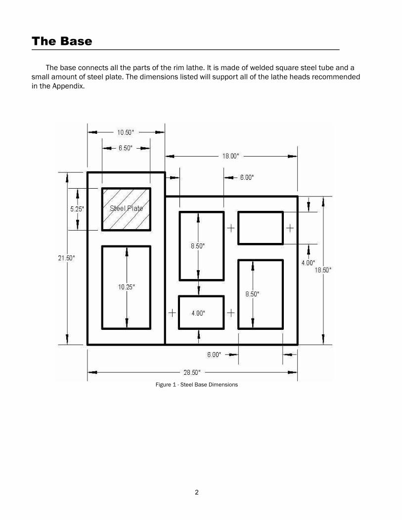
The base connects all the parts of the rim lathe. It is made of welded square steel tube and a small amount of steel plate. The dimensions listed will support all of the lathe heads recommended in the Appendix.
Figure 1 - Steel Base Dimensions
3
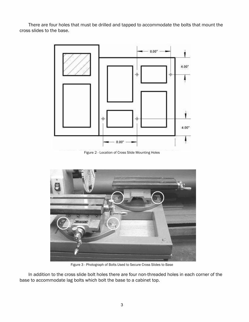
There are four holes that must be drilled and tapped to accommodate the bolts that mount the cross slides to the base.
Figure 2 - Location of Cross Slide Mounting Holes
Figure 3 - Photograph of Bolts Used to Secure Cross Slides to Base
In addition to the cross slide bolt holes there are four non-threaded holes in each corner of the
base to accommodate lag bolts which bolt the base to a cabinet top.
4
Typical Mounting for Lathe Head
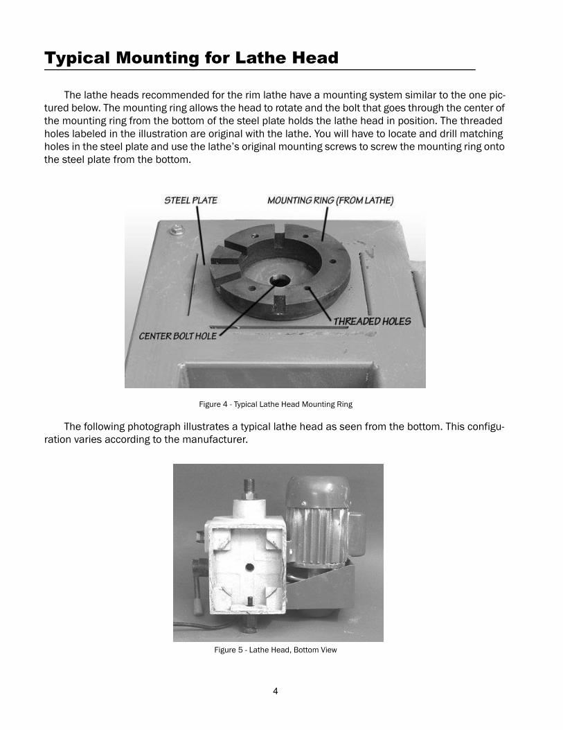
The lathe heads recommended for the rim lathe have a mounting system similar to the one pic-tured below. The mounting ring allows the head to rotate and the bolt that goes through the center of the mounting ring from the bottom of the steel plate holds the lathe head in position. The threaded
holes labeled in the illustration are original with the lathe. You will have to locate and drill matching holes in the steel plate and use the lathe’s original mounting screws to screw the mounting ring onto
the steel plate from the bottom.
Figure 4 - Typical Lathe Head Mounting Ring
The following photograph illustrates a typical lathe head as seen from the bottom. This configu-ration varies according to the manufacturer.
Figure 5 - Lathe Head, Bottom View
5
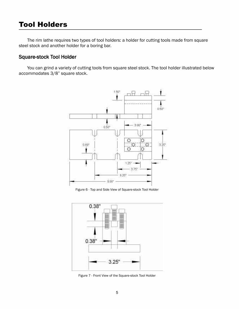
Tool Holders
The rim lathe requires two types of tool holders: a holder for cutting tools made from square steel stock and another holder for a boring bar.
Square-stock Tool HolderSquare-stock Tool HolderSquare-stock Tool HolderSquare-stock Tool Holder
You can grind a variety of cutting tools from square steel stock. The tool holder illustrated below
accommodates 3/8” square stock.
Figure 6 - Top and Side View of Square-stock Tool Holder
Figure 7 - Front View of the Square-stock Tool Holder
6
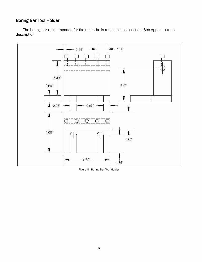
Boring Bar Tool HolderBoring Bar Tool HolderBoring Bar Tool HolderBoring Bar Tool Holder
The boring bar recommended for the rim lathe is round in cross section. See Appendix for a
description.
Figure 8 - Boring Bar Tool Holder
7
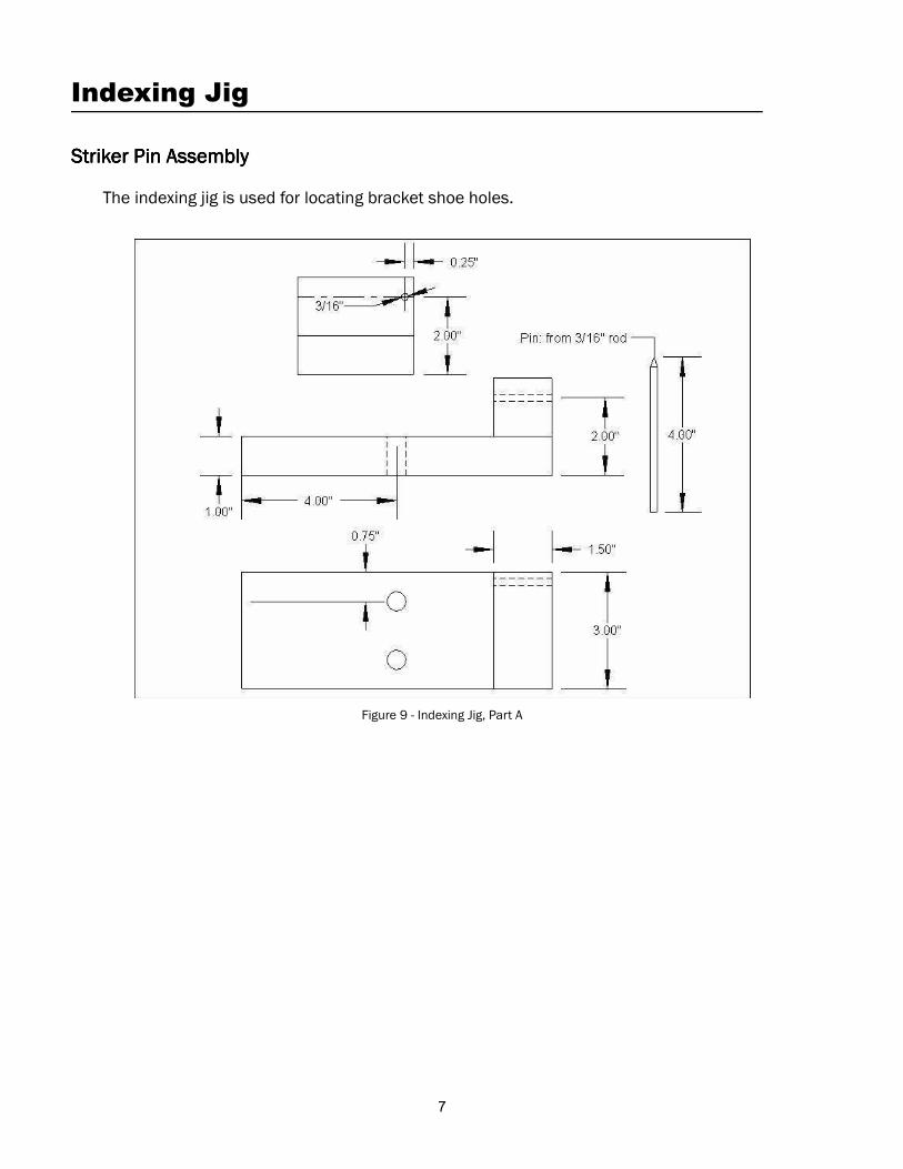
Indexing Jig
Striker Pin AssemblyStriker Pin AssemblyStriker Pin AssemblyStriker Pin Assembly
The indexing jig is used for locating bracket shoe holes.
Figure 9 - Indexing Jig, Part A
8
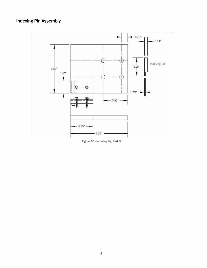
Indexing Pin AssemblyIndexing Pin AssemblyIndexing Pin AssemblyIndexing Pin Assembly
Figure 10 - Indexing Jig, Part B
A-1
Appendix
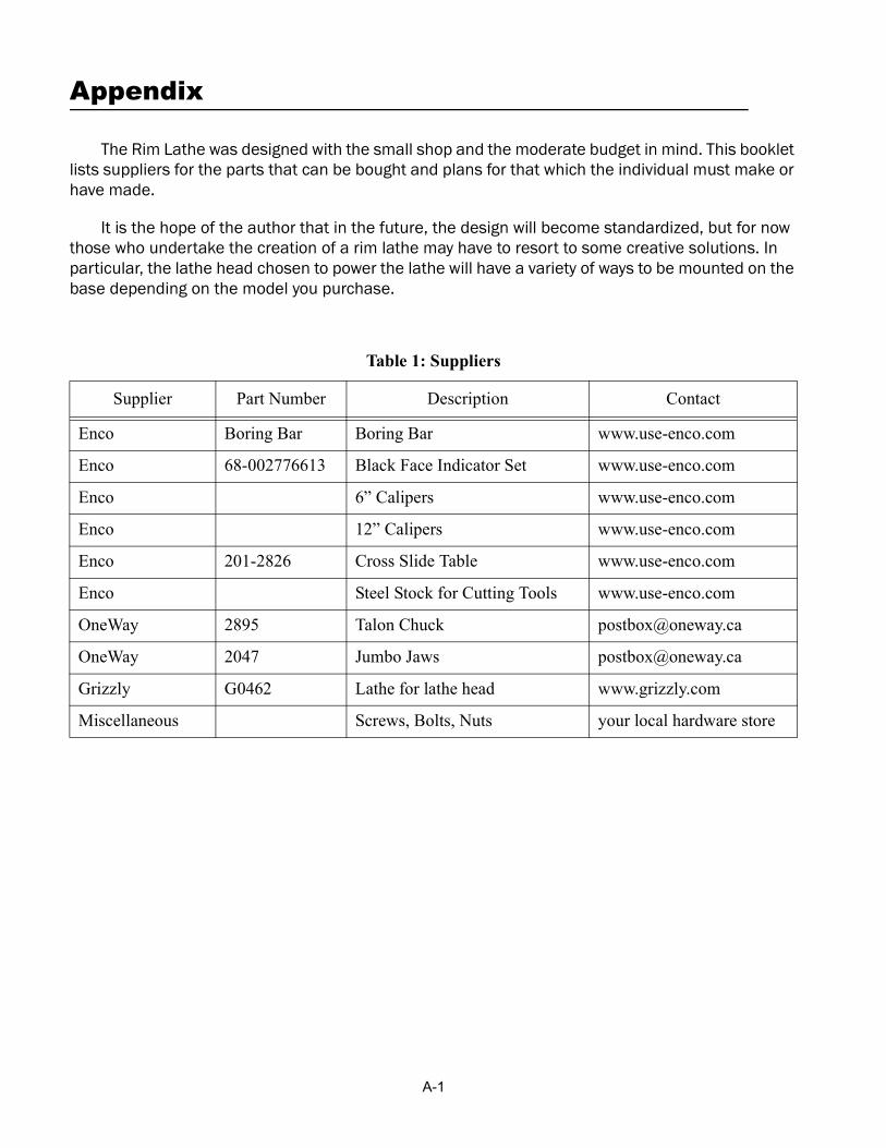
The Rim Lathe was designed with the small shop and the moderate budget in mind. This booklet lists suppliers for the parts that can be bought and plans for that which the individual must make or have made.
It is the hope of the author that in the future, the design will become standardized, but for now those who undertake the creation of a rim lathe may have to resort to some creative solutions. In
particular, the lathe head chosen to power the lathe will have a variety of ways to be mounted on the base depending on the model you purchase.
Table 1: Suppliers
Supplier Part Number Description Contact
Enco Boring Bar Boring Bar www.use-enco.com
Enco 68-002776613 Black Face Indicator Set www.use-enco.com
Enco 6” Calipers www.use-enco.com
Enco 12” Calipers www.use-enco.com
Enco 201-2826 Cross Slide Table www.use-enco.com
Enco Steel Stock for Cutting Tools www.use-enco.com
OneWay 2895 Talon Chuck [email protected]
OneWay 2047 Jumbo Jaws [email protected]
Grizzly G0462 Lathe for lathe head www.grizzly.com
Miscellaneous Screws, Bolts, Nuts your local hardware store