Embed Size (px)
Citation preview
www.reinhausen.com Voltage Regulator TAPCON® 230Operating Instructions BA 225/03
2 225/03 en
NOTE
Changes may have been made to a product after going to press with this documentation.We expressly reserve the right to make changes to a product’s technical data and design as well as changes tothe scope of delivery.
In all cases, the information submitted and agreements concluded during processing of the quotation and orderin question shall be binding.
Contents
Contents
1 General .............................................................................................................................................................................................................. 4
1.1 Safety instructions ............................................................................................................................................................................. 4
1.2 Specified application ........................................................................................................................................................................ 4
1.3 Design and performance features of the TAPCON® 230 ........................................................................................................ 5
2 Technical Data ................................................................................................................................................................................................ 6
3 Operation .......................................................................................................................................................................................................... 9
3.1 Input and output of data; functions ............................................................................................................................................ 9
3.2 Description of the front panel ....................................................................................................................................................... 9
3.2.1 Display .................................................................................................................................................................................... 10
4 Parametering .................................................................................................................................................................................................. 11
4.1 Normset setting .................................................................................................................................................................................. 11
4.2 Setting the desired voltage level 1 ............................................................................................................................................... 11
4.3 Setting the bandwidth ..................................................................................................................................................................... 11
4.4 Setting the delay time T1 or T2 (DELAY 1/DELAY 2) and pulse duration (option) ........................................................... 12
4.5 Setting the overvoltage detection (U>) with automatic return control ............................................................................. 13
4.6 Setting the undervoltage blocking (U<) ..................................................................................................................................... 13
4.7 Setting the overcurrent blocking (I>) .......................................................................................................................................... 13
4.8 Measuring transformers (VT, CT configuration) ......................................................................................................................... 14
4.9 Setting the desired voltage levels DVL2 and DVL3 ................................................................................................................... 15
4.10 Line compensation ............................................................................................................................................................................ 15
4.10.1 Line drop compensation (LDC) ......................................................................................................................................... 15
4.10.2 Z-Compensation ................................................................................................................................................................... 16
4.11 Analog remote position indication (option) .............................................................................................................................. 16
4.12 Voltage regulator identification .................................................................................................................................................... 17
4.13 Setting the unit to V or kV ............................................................................................................................................................... 17
4.14 Selection of the display in the 4th line of the display .............................................................................................................. 17
4.15 Language selection ........................................................................................................................................................................... 17
3225/03 en
Contents
5 Commissioning ............................................................................................................................................................................................... 18
5.1 Installation ........................................................................................................................................................................................... 18
5.2 Connection .......................................................................................................................................................................................... 18
5.3 Easy setting of operating modes with NORMSET ...................................................................................................................... 19
5.4 Function tests; operational settings ............................................................................................................................................. 19
5.5 Manual control of the on-load tap-changer ............................................................................................................................. 20
6 Parallel control without system topology (Option) ......................................................................................................................... 21
6.1 Parallel operation with "Minimum Circulating Reactive Current Method“ ....................................................................... 22
6.1.1 System configuration, settings ........................................................................................................................................ 226.1.2 Setting the interference variable (CIRCUL. REAC. CURR. STABILITY) ....................................................................... 226.1.3 Setting the bandwidth for circulating reactive current (blocking threshold) .................................................... 226.1.4 Function tests, commissioning ........................................................................................................................................ 23
6.1.4.1 Preliminary settings ........................................................................................................................................... 236.1.4.2 Setting the interference variable (CIRCUL. REAC. CURR. STABILITY) ..................................................... 236.1.4.3 Setting the circulating reactive current monitoring
(CIRCUL. REAC. CURR. MON. BANDWIDTH) ............................................................................................... 23
6.2 Parallel operation according to synchronized tap-change operation Master/ Follower ............................................ 23
6.2.1 System configuration, settings, transfer of the on-load tap-changer setting ................................................ 246.2.1.1 Setting the tapping position range ............................................................................................................. 246.2.1.2 Selecting the Master/Follower operation .................................................................................................. 25
6.2.2 Function tests, commissioning and preliminary settings ........................................................................................ 25
6.3 Parallel operation with an existing parallel control unit SKB 30 to the principle of„minimum circulating reactive current“ .................................................................................................................................... 26
6.4 Disturbances during parallel operation ...................................................................................................................................... 26
7 Appendix ........................................................................................................................................................................................................... 27
NOTE
A "PARAM?" message appearing in the first line of the display indicates a negative result of the parameter verification that maybe caused by interference above the permissible electromagnetic compatibility limit (see information on standardisation andverification in section 2). In this case, voltage regulation is blocked for safety reasons.Check the settings in order to clear the blocking. Press and hold the "SELECT" key and press the "�" or "�" key for displayingthe current settings (see section 3.2.1). Voltage regulation is reinstated once invalid settings have been corrected while cyclingthrough the menu. The status LEDs and status relays are activated, and the display shows the current measurement readings.
4 225/03 en
WARNING
This information indicates particular danger to life andhealth. Disregarding such a warning can lead to serious orfatal injury.
CAUTION
This information indicates particular danger to the equip-ment or other property of the user. Serious or fatal injurycannot be excluded.
NOTE
These notes give important information on a certainsubject.
CAUTION
Installation, electrical connection and commissioning ofthe electronic voltage regulator may only be carried outby qualified, skilled personnel and only in accordance withthese operating instructions.It is the responsibility of the user to make sure that theelectronic voltage regulator is used for the specificapplication only. For safety reasons, any unauthorized andimproperly executed works, i. e. installation, modification,alteration of the equipment, electrical connection, orcommissioning of the equipment, are forbidden withoutfirst consulting MR!The trouble-free operation of the drive, the on-load tap-changer, and the transformer may be put at risk.
1.2 Specified application
The electronic voltage regulator TAPCON® 230 serves forautomatic control of transformers with a motor-driven on-load tap-changer. The motor-drive mechanism receives thecorresponding control commands from the voltage regulator.With these commands, the on-load tap-changer moves tothe next position and the transformer’s voltage value isadapted to the preset desired voltage level.
To allow individual adaptation of the control system to thevarious field service conditions encountered, influencingvariables such as time delay, bandwidth, and even line-dependent and load-dependent parameters can be pro-grammed for compensation of voltage-dependent and/orcurrent-dependent limits. As a special feature, the voltageregulator is also capable of controlling parallel transformeroperation.
WARNING
All relevant fire protection regulations must be strictlyobserved.
1 General
1 General
1.1 Safety instructions
All personnel involved in installation, commissioning,maintenance or repair of this equipment must:
- be suitably qualified and- strictly observe these operating instructions.
Improper operation or misuse can lead to- serious or fatal injury,- damage to the equipment and property of the user
and- a reduction in the efficiency of the equipment.
Safety instructions in this manual are presented in threedifferent forms to emphasize important information.
5225/03 en
1 General
1.3 Design and performance features of theTAPCON® 230
The electronic voltage regulator TAPCON® 230 is mounted ina protective housing with hinged cover and inspection win-dow. The protective housing is suitable for both flush andprojected panel mounting.The front panel contains several function keys for setting theindividual operating parameters.
Display of the operating status is achieved by a 4-line,16-digit alphanumeric LC display and light emitting diodes.
The electronic voltage regulator is controlled by a micro-controller (see appendix, block/connection diagram).Besides a voltage transformer and a current transformer itcontains optocoupler inputs with potential separation as wellas potential-free output relay contacts.
Apart from the usual well-known, versatile and individualsetting options for the MR control system, the TAPCON® 230voltage regulator also offers the option of fast and easyparametering by introducing the innovative "Normset"function.
The term „Normset“ function stands for an automatismwhich considerably simplifies the configuration of a voltageregulator. If the desired voltage level is entered while the„Normset“ function is active, the voltage regulator willexamine the given line/network conditions and proceed toperform an automatic adaptation of all further inputs(comprised in part of the pre-parametering and standardreference values) which used to be required for customaryregulators (also refer to the standard configuration accord-ing to Sub-menu 2).
The parameters of the regulator can be set by means of a PCvia the incorporated serial interface (RS232) integrated inthe regulator; the appropriate PC software will be furnishedby MR.
A load-dependent line-voltage drop, e. g. of a spur line lead-ing from the transformer to the load, can be compensatedeither by line simulation (Line Drop Compensation) or byload-current dependent increase of the voltage level(Z compensation).
Trouble-free operation is ensured by the regulator’s inherentundervoltage blocking, overcurrent blocking and overvoltagemonitoring.
NOTE
When voltage regulation is effected by tap transformersand voltage regulators, it is assumed that a change of thetap position results in a significant voltage change. Whengenerators feed the voltage level to be regulated, however,quite different conditions may result so that a correctregulation of the voltage cannot be guaranteed. In suchcases MR should be consulted as early as the planningstage.
The functions of the TAPCON® 230 voltage regulator are justabout fully compatible with those of the earlier generationsof voltage regulators.
Parallel operation follows the principles of either minimumcirculating reactive current or the Master/Follower principle.
Parallel control of two groups comprised of up to 8 userstotal is possible without the need for a supplementary devicedue to the utilization of a serial bus system.
6 225/03 en
2 Technical Data
2 Technical Data
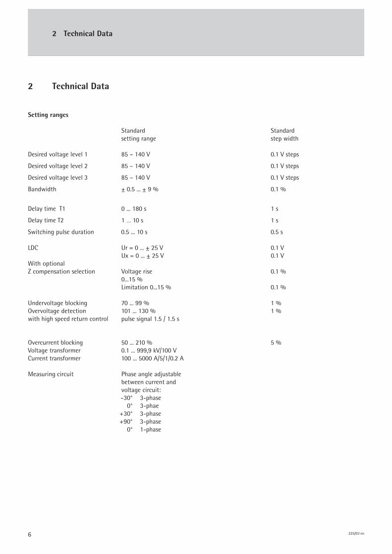
Setting ranges
Standard Standardsetting range step width
Desired voltage level 1 85 – 140 V 0.1 V steps
Desired voltage level 2 85 – 140 V 0.1 V steps
Desired voltage level 3 85 – 140 V 0.1 V steps
Bandwidth ± 0.5 ... ± 9 % 0.1 %
Delay time T1 0 ... 180 s 1 s
Delay time T2 1 … 10 s 1 s
Switching pulse duration 0.5 ... 10 s 0.5 s
LDC Ur = 0 ... ± 25 V 0.1 VUx = 0 ... ± 25 V 0.1 V
With optionalZ compensation selection Voltage rise 0.1 %
0...15 %Limitation 0...15 % 0.1 %
Undervoltage blocking 70 ... 99 % 1 %Overvoltage detection 101 ... 130 % 1 %with high speed return control pulse signal 1.5 / 1.5 s
Overcurrent blocking 50 ... 210 % 5 %Voltage transformer 0.1 ... 999,9 kV/100 VCurrent transformer 100 ... 5000 A/5/1/0.2 A
Measuring circuit Phase angle adjustablebetween current andvoltage circuit:-30° 3-phase 0° 3-phae
+30° 3-phase+90° 3-phase 0° 1-phase

7225/03 en
2 Technical Data
Display 4-line, 16-digit LC display
1 LED lamp (green) for signalling status1 LED lamp (red) each for signalling U<, U>, I>1 LED lamp (green) for signalling ‚parallel operation active’ status1 LED lamp (green) for signalling ‚Normset active’ status
Inputs and outputs Input relays Output relays
1x manual control mode Rating of relay contacts:1x automatic control mode AC: 250 V 5 A1x group 1 parallel (optional) DC: 30 V 5 A; 110 V 0.4 A;1x group 2 parallel (optional) 220 V 0.3 A1x high-speed circuit breaker of voltage 1 x raise
limit monitoring indicator 1 x lower1 x analogue input of tapping position (optional) 1 x automatic control mode4 - 20 mA; potentiometer 1 x status1 x desired voltage level 2 1x group interrupt U<, U>, I>1 x desired voltage level 3 1x monitoring (function monitoring)
Voltage transformer 85 ... 140 V, measuring range 60 ... 185 V,r.m.s. value 40 ... 60 Hz, intrinsic consumption < 1 VA
Current transformer 0.2 / 1 / 5 A, 40 ... 60 Hz, r.m.s. valueintrinsic consumption < 1 VA,overload capacity 2x In continuously, 100x In/1 s
Measuring errors Voltage measuring: < 0.3 % ± 40 ppm/°CCurrent measuring: < 0.5 % ± 40 ppm/°C
Serial interfaces 1 x serial interface RS232 (COM1) forparametering via PCoptionally1 x CAN bus for parall operation1 x RS232 for parallel operation with digital MR parallel control unit SKB
Power supply 115 V (+25 % - 35 %) 40 - 60 Hz, can be changed over either fromthe measuring voltage or by separate change-over in the factory toa supply voltage of 230 VPower consumption approx. 5.5 VA (at 115V, idle state)
8 225/03 en
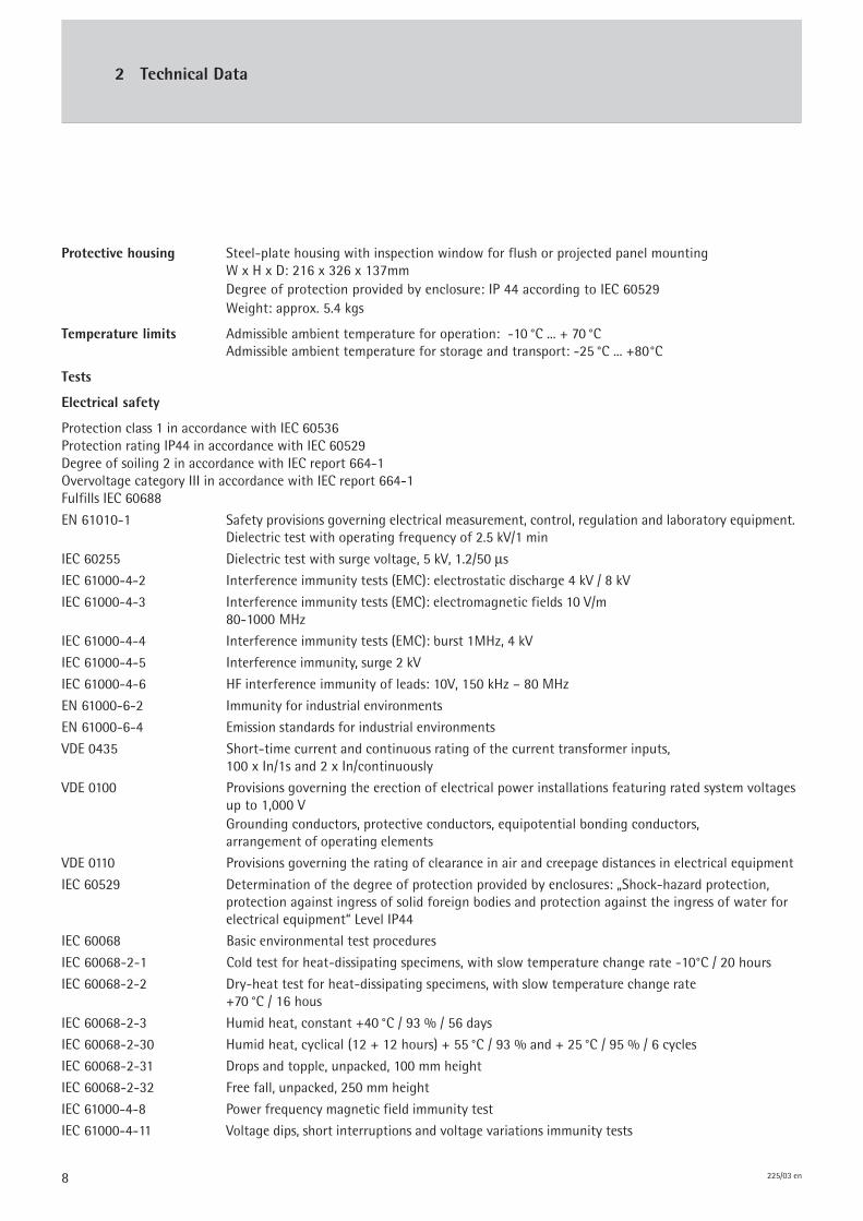
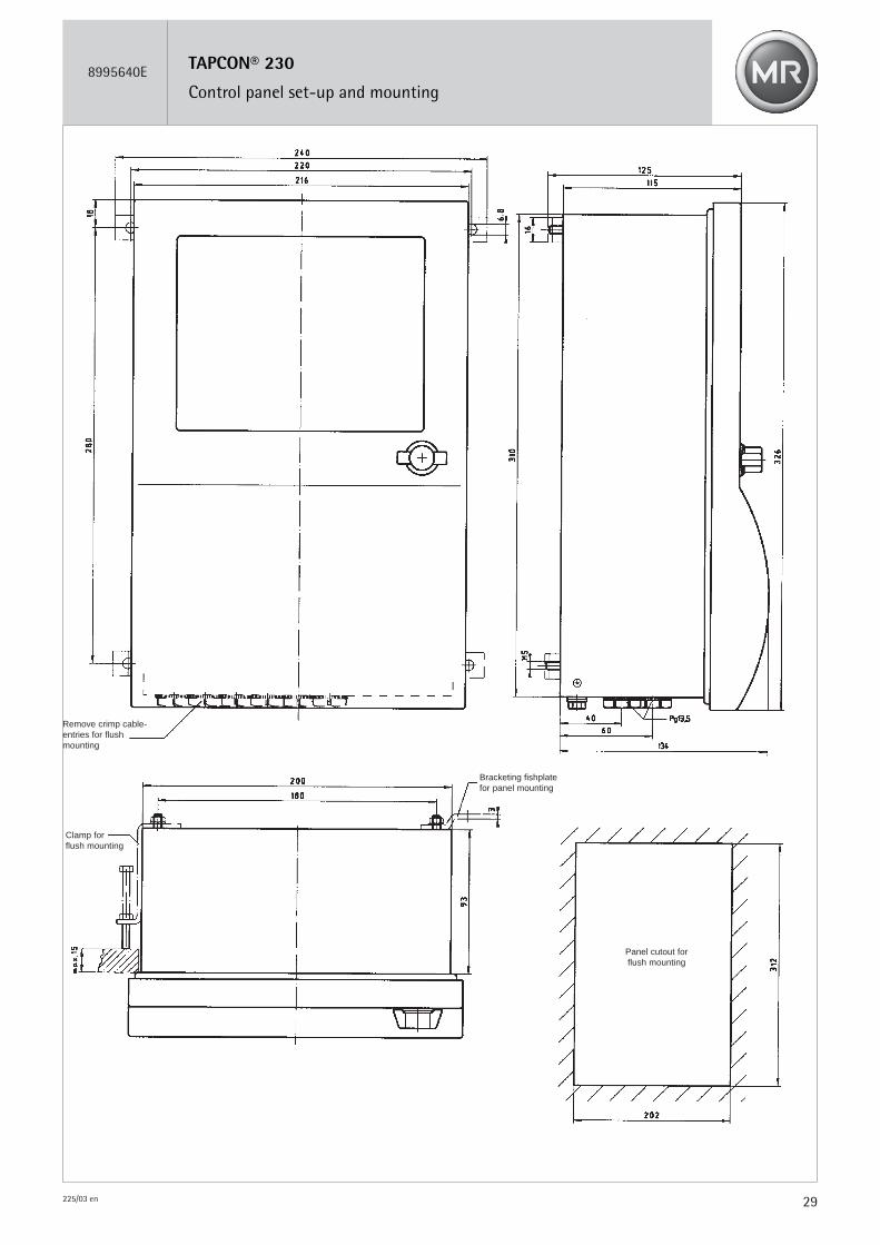
Protective housing Steel-plate housing with inspection window for flush or projected panel mountingW x H x D: 216 x 326 x 137mmDegree of protection provided by enclosure: IP 44 according to IEC 60529Weight: approx. 5.4 kgs
Temperature limits Admissible ambient temperature for operation: -10 °C ... + 70 °CAdmissible ambient temperature for storage and transport: -25 °C ... +80 °C
Tests
Electrical safety
Protection class 1 in accordance with IEC 60536Protection rating IP44 in accordance with IEC 60529Degree of soiling 2 in accordance with IEC report 664-1Overvoltage category III in accordance with IEC report 664-1Fulfills IEC 60688
EN 61010-1 Safety provisions governing electrical measurement, control, regulation and laboratory equipment.Dielectric test with operating frequency of 2.5 kV/1 min
IEC 60255 Dielectric test with surge voltage, 5 kV, 1.2/50 μs
IEC 61000-4-2 Interference immunity tests (EMC): electrostatic discharge 4 kV / 8 kV
IEC 61000-4-3 Interference immunity tests (EMC): electromagnetic fields 10 V/m80-1000 MHz
IEC 61000-4-4 Interference immunity tests (EMC): burst 1MHz, 4 kV
IEC 61000-4-5 Interference immunity, surge 2 kV
IEC 61000-4-6 HF interference immunity of leads: 10V, 150 kHz – 80 MHz
EN 61000-6-2 Immunity for industrial environments
EN 61000-6-4 Emission standards for industrial environments
VDE 0435 Short-time current and continuous rating of the current transformer inputs,100 x In/1s and 2 x In/continuously
VDE 0100 Provisions governing the erection of electrical power installations featuring rated system voltagesup to 1,000 VGrounding conductors, protective conductors, equipotential bonding conductors,arrangement of operating elements
VDE 0110 Provisions governing the rating of clearance in air and creepage distances in electrical equipment
IEC 60529 Determination of the degree of protection provided by enclosures: „Shock-hazard protection,protection against ingress of solid foreign bodies and protection against the ingress of water forelectrical equipment“ Level IP44
IEC 60068 Basic environmental test procedures
IEC 60068-2-1 Cold test for heat-dissipating specimens, with slow temperature change rate -10°C / 20 hours
IEC 60068-2-2 Dry-heat test for heat-dissipating specimens, with slow temperature change rate+70 °C / 16 hous
IEC 60068-2-3 Humid heat, constant +40 °C / 93 % / 56 days
IEC 60068-2-30 Humid heat, cyclical (12 + 12 hours) + 55 °C / 93 % and + 25 °C / 95 % / 6 cycles
IEC 60068-2-31 Drops and topple, unpacked, 100 mm height
IEC 60068-2-32 Free fall, unpacked, 250 mm height
IEC 61000-4-8 Power frequency magnetic field immunity test
IEC 61000-4-11 Voltage dips, short interruptions and voltage variations immunity tests
2 Technical Data
9225/03 en
3 Operation
�
��
��
�
�
1
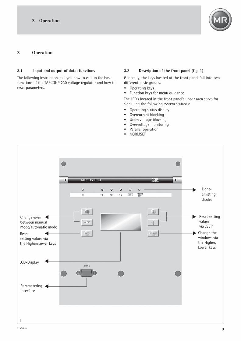
Resetsetting values viathe Higher/Lower keys
Change-overbetween manualmode/automatic mode
LCD-Display
Parameteringinterface
Light-emittingdiodes
Change thewindows viathe Higher/Lower keys
Reset settingvaluesvia „SET“
3 Operation
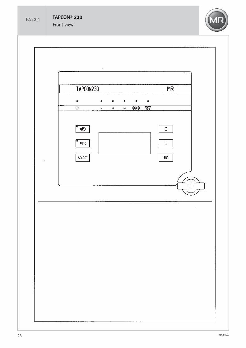
3.2 Description of the front panel (fig. 1)
Generally, the keys located at the front panel fall into twodifferent basic groups.• Operating keys• Function keys for menu guidance
The LED’s located in the front panel’s upper area serve forsignalling the following system statuses:
• Operating status display• Overcurrent blocking• Undervoltage blocking• Overvoltage monitoring• Parallel operation• NORMSET
3.1 Input and output of data; functions
The following instructions tell you how to call up the basicfunctions of the TAPCON® 230 voltage regulator and how toreset parameters.

10 225/03 en
LDC UR0.0V(-25.0V - 25.0V)
15/30
LDC UX0.0V(-25.0V - 25.0V)
16/30
CAN ADRESS0(1- 8)
25/30
VOLT.REG.IDENTIFIER1111(0- 9999)
26/30
DISPLAY V/kVkV(V/ kV)
28/30
SELECTION 4th LINECURRENT I(I,S,Q,P,PHI,..)
29/30
BANDWIDTH9.0%(0.5% - 9%)
03/30
Z-COMP VOLTRISE0.0%(0.0% - 15.0%)
17/30
Z-COMP LIMIT0.0%(0%- 15.0%)
18/30
SELECT PARALLELCIRCUL.REAC.CURR.CRC/MAST/FOLLOW
19/30
POS MIN1(-35 – 35)
20/30
POS MAX35(-35 – 35)
21/30
CIRCUL.REAC.CURR.STABILITY0.0(0.0- 100.0) 23/30
CIRCUL.REAC.CURR.BANDWIDTH20%(0.5% - 20.0%)24/30
NORMSETONON/ OFF
01/30
DES.VOLTAGE LEVEL DVL1100V
(85V- 140V)02/30
DELAY T110s(0s- 180s)
04/30
T1 LINEAR INTEGRALLINEAR(LINEAR/INTEGRAL)
05/30
DELAY T210s(PERM,1-10s,OFF)
06/30
OVERVOLTAGE U>105%(101%-130%)
07/30
UNDERVOLTAGE U<70%(70%- 99%)
08/30
OVERCURRENT I>110%(50% -210%)
09/30
NOM.TRANSF.VOLTAGE10.0V(0.1kV- 999.9kV)
10/30
CURRENT100A(100A- 5000A)
11/30
TRANSFORMER PHASE90 3 PH(30,0,30,90,1PH)
12/30
DES.VOLT.LEVEL DVL2100V(85V- 140.0V)
13/30
DES.VOLT.LEVEL DV3100.0V(85.0V- 140.0V)
14/30
< <
LANGUAGEGERMANGER/GB/F/E
30/30
TAPPING DIRECTIONNEGATIVEPOSITIVE / NEGATIVE
22/30
3 Operation
< <
H/T PULSE DURATION0,5 s(0.0 s - 10.0 s)
27/30
3.2.1 Display
The TAPCON® 230 contains a 4-line, 16-digit LC display.A distinction is made between the two following types ofdisplays: Basic display and parametering display.
a) Basic displayIn addition to the actual voltage level, the desired voltagelevel and the deviations the basic display indicates anadditional measuring value in the 4th line during normaloperation. Selection of this measuring value in the displaywindow „SELECT 4th LINE“.The following values are available:- Current I - Power factor cos PHI- Apparent power S - Frequency f- Reactive power Q - Status line- Active power P - Position, optional- Phase angle PHI
ACTUAL VOLT.LEVEL 64.90 kVDESIRED VOLT.LEVEL 66.00 kVdU% 1.67 %CURRENT I 253 A
b) Parametering display windowsThe TAPCON® 230 contains parametering display windowswhich serve to display set parameters and allow the user tomodify any previously set parameters to suit his specifica-tions.Generally, these windows are set up as follows:- 1st line: Title/designation of the parameter- 2nd line: Set value- 3rd line: Possible setting values and/or setting limits- 4th line: Serial number of the display
DESIRED VOLT.LEVEL SW1110V(85V- 140V)
02/30
The displays are situated behind one another in a ring-shaped arrangement, as shown in the illustration to the right,and can be selected by operating the function keys SELECTand . The display will remain visible for as long asthe SELECT key is being pressed, plus an additional 10seconds after the SELECT key was released. It is possible tomove in both directions within the menu. As a result, displayno. 30 of the basic display can be reached just as quickly asdisplay no. 1.The preset value can be altered within the setting values and/or setting limits by operating the SET and func-tion keys. Once the SET key is released, the new value will beset to ‚active’.For parametering purposes, please use the displays listedbelow, the functions of which are explained in detail in thefollowing.
11225/03 en
4 Parametering
4 Parametering
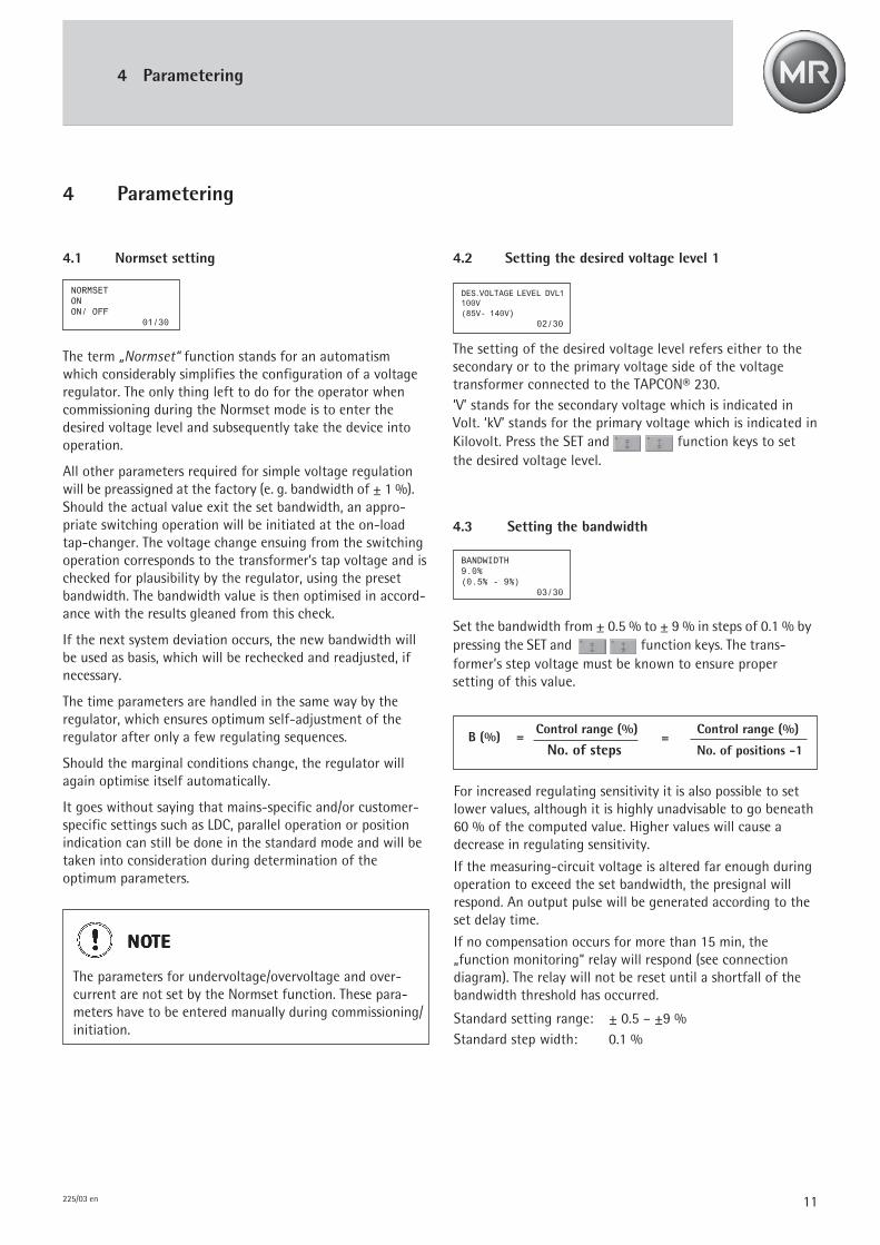
4.1 Normset setting
The term „Normset“ function stands for an automatismwhich considerably simplifies the configuration of a voltageregulator. The only thing left to do for the operator whencommissioning during the Normset mode is to enter thedesired voltage level and subsequently take the device intooperation.
All other parameters required for simple voltage regulationwill be preassigned at the factory (e. g. bandwidth of ± 1 %).Should the actual value exit the set bandwidth, an appro-priate switching operation will be initiated at the on-loadtap-changer. The voltage change ensuing from the switchingoperation corresponds to the transformer’s tap voltage and ischecked for plausibility by the regulator, using the presetbandwidth. The bandwidth value is then optimised in accord-ance with the results gleaned from this check.
If the next system deviation occurs, the new bandwidth willbe used as basis, which will be rechecked and readjusted, ifnecessary.
The time parameters are handled in the same way by theregulator, which ensures optimum self-adjustment of theregulator after only a few regulating sequences.
Should the marginal conditions change, the regulator willagain optimise itself automatically.
It goes without saying that mains-specific and/or customer-specific settings such as LDC, parallel operation or positionindication can still be done in the standard mode and will betaken into consideration during determination of theoptimum parameters.
4.2 Setting the desired voltage level 1
The setting of the desired voltage level refers either to thesecondary or to the primary voltage side of the voltagetransformer connected to the TAPCON® 230.‘V’ stands for the secondary voltage which is indicated inVolt. ‘kV’ stands for the primary voltage which is indicated inKilovolt. Press the SET and function keys to setthe desired voltage level.
NONONONONOTETETETETE
The parameters for undervoltage/overvoltage and over-current are not set by the Normset function. These para-meters have to be entered manually during commissioning/initiation.
DES.VOLTAGE LEVEL DVL1100V
(85V- 140V)02/30
4.3 Setting the bandwidth
Set the bandwidth from ± 0.5 % to ± 9 % in steps of 0.1 % bypressing the SET and function keys. The trans-former’s step voltage must be known to ensure propersetting of this value.
BANDWIDTH9.0%(0.5% - 9%)
03/30
B (%) = Control range (%)=
Control range (%)
No. of steps No. of positions -1
For increased regulating sensitivity it is also possible to setlower values, although it is highly unadvisable to go beneath60 % of the computed value. Higher values will cause adecrease in regulating sensitivity.
If the measuring-circuit voltage is altered far enough duringoperation to exceed the set bandwidth, the presignal willrespond. An output pulse will be generated according to theset delay time.
If no compensation occurs for more than 15 min, the„function monitoring“ relay will respond (see connectiondiagram). The relay will not be reset until a shortfall of thebandwidth threshold has occurred.
Standard setting range: ± 0.5 – ±9 %Standard step width: 0.1 %
NORMSETONON/ OFF
01/30
12 225/03 en
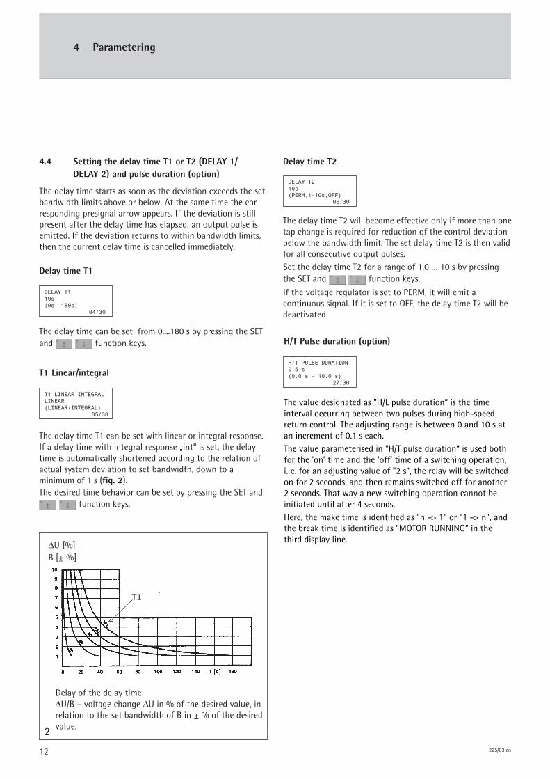
ΔU [%]B [± %]
2
T1
<
4 Parametering
Delay of the delay timeΔU/B – voltage change ΔU in % of the desired value, inrelation to the set bandwidth of B in ± % of the desiredvalue.
Delay time T2
The delay time T2 will become effective only if more than onetap change is required for reduction of the control deviationbelow the bandwidth limit. The set delay time T2 is then validfor all consecutive output pulses.Set the delay time T2 for a range of 1.0 … 10 s by pressingthe SET and function keys.
If the voltage regulator is set to PERM, it will emit acontinuous signal. If it is set to OFF, the delay time T2 will bedeactivated.
DELAY T210s(PERM,1-10s,OFF)
06/30
T1 Linear/integral
The delay time T1 can be set with linear or integral response.If a delay time with integral response „Int“ is set, the delaytime is automatically shortened according to the relation ofactual system deviation to set bandwidth, down to aminimum of 1 s (fig. 2).The desired time behavior can be set by pressing the SET and
function keys.
4.4 Setting the delay time T1 or T2 (DELAY 1/DELAY 2) and pulse duration (option)
The delay time starts as soon as the deviation exceeds the setbandwidth limits above or below. At the same time the cor-responding presignal arrow appears. If the deviation is stillpresent after the delay time has elapsed, an output pulse isemitted. If the deviation returns to within bandwidth limits,then the current delay time is cancelled immediately.
Delay time T1
The delay time can be set from 0....180 s by pressing the SETand function keys.
DELAY T110s(0s- 180s)
04/30
T1 LINEAR INTEGRALLINEAR(LINEAR/INTEGRAL)
05/30
H/T Pulse duration (option)
The value designated as "H/L pulse duration“ is the timeinterval occurring between two pulses during high-speedreturn control. The adjusting range is between 0 and 10 s atan increment of 0.1 s each.The value parameterised in "H/T pulse duration“ is used bothfor the 'on’ time and the 'off’ time of a switching operation,i. e. for an adjusting value of "2 s“, the relay will be switchedon for 2 seconds, and then remains switched off for another2 seconds. That way a new switching operation cannot beinitiated until after 4 seconds.Here, the make time is identified as "n –> 1" or "1 –> n", andthe break time is identified as "MOTOR RUNNING“ in thethird display line.
H/T PULSE DURATION0.5 s(0.0 s - 10.0 s)
27/30
13225/03 en
4 Parametering
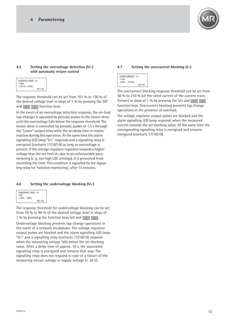
4.5 Setting the overvoltage detection (U>)with automatic return control
The response threshold can be set from 101 % to 130 % ofthe desired voltage level in steps of 1 % by pressing the SETand function keys.
In the event of an overvoltage detection response, the on-loadtap-changer is operated by periodic pulses to the motor-driveuntil the overvoltage falls below the response threshold. Themotor-drive is controlled by periodic pulses of 1.5 s throughthe "Lower“ output relay while the set delay time re-mainsinactive during this operation. At the same time the alarmsignalling LED lamp "U>" responds and a signalling relay isenergized (contacts 17/18/19) as long as overvoltage ispresent. If the voltage regulator regulates towards a highervoltage than the set limit U> due to an unfavourable para-metering (e. g. too high LDC settings), it is prevented fromexceeding the limit. This condition is signalled by the signal-ling relay for ‘function monitoring’, after 15 minutes.
4.6 Setting the undervoltage blocking (U<)
The response threshold for undervoltage blocking can be setfrom 70 % to 99 % of the desired voltage level in steps of1 % by pressing the function keys Set and .
Undervoltage blocking prevents tap change operations inthe event of a network breakdown. The voltage regulatoroutput pulses are blocked and the alarm signalling LED lamp"U<" and a signalling relay (contacts 17/18/19) respondwhen the measuring voltage falls below the set blockingvalue. After a delay time of approx. 10 s, the associatedsignalling relay is energized and remains that way. Thesignalling relay does not respond in case of a failure of themeasuring-circuit voltage or supply voltage (< 30 V).
UNDERVOLTAGE U<70%(70%- 99%)
08/30
OVERVOLTAGE U>105%(101%-130%)
07/30
4.7 Setting the overcurrent blocking (I>)
The overcurrent blocking response threshold can be set from50 % to 210 % (of the rated current of the current trans-former) in steps of 1 % by pressing the Set and function keys. Overcurrent blocking prevents tap changeoperations in the presence of overload.
The voltage regulator output pulses are blocked and thealarm signalling LED lamp responds when the measuredcurrent exceeds the set blocking value. At the same time thecorresponding signalling relay is energized and remainsenergized (contacts 17/18/19).
OVERCURRENT I>110%(50% -210%)
09/30
14 225/03 en
4 Parametering
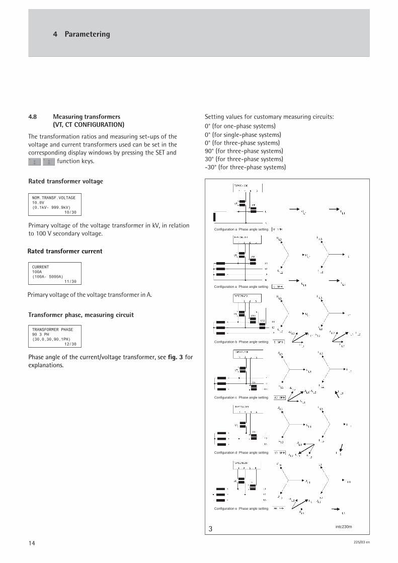
Setting values for customary measuring circuits:0° (for one-phase systems)0° (for single-phase systems)0° (for three-phase systems)90° (for three-phase systems)30° (for three-phase systems)-30° (for three-phase systems)
4.8 Measuring transformers(VT, CT CONFIGURATION)
The transformation ratios and measuring set-ups of thevoltage and current transformers used can be set in thecorresponding display windows by pressing the SET and
function keys.
Rated transformer current
Primary voltage of the voltage transformer in A.
Rated transformer voltage
Primary voltage of the voltage transformer in kV, in relationto 100 V secondary voltage.
Transformer phase, measuring circuit
Phase angle of the current/voltage transformer, see fig. 3 forexplanations.
NOM.TRANSF.VOLTAGE10.0V(0.1kV- 999.9kV)
10/30
CURRENT100A(100A- 5000A)
11/30
TRANSFORMER PHASE90 3 PH(30,0,30,90,1PH)
12/30
3 intc230m
Configuration a Phase angle setting
Configuration a Phase angle setting
Configuration b Phase angle setting
Configuration c Phase angle setting
Configuration d Phase angle setting
Configuration e Phase angle setting
15225/03 en
4 Parametering
intVC13a4
The voltage regulator TAPCON® 230 permits the preselectionof three different desired voltage levels, each of which willbe activated specifically in relation to the actuation of inputs13 and 14.No signal present at terminals 13 and 14 => Desired voltage
level 1 is activePresence of a signal at terminal 13 => Desired voltage
level 2 is activePresence of a signal at terminal 14 => Desired voltage
level 3 is active
Setting the desired voltage levels 2 and 3 is identical to thesetting procedure for the desired voltage level 1, i. e. byoperating the function keys SET and .
4.10 Line compensation
The line compensation, i. e. the inclusion of the voltage dropof a line connected to the transformer in the regulatingprocess, can be accomplished in two different ways.
Comparison between LDC and Z CompensationApplication of the vectorial compensation (LDC):- requires knowledge of the exact line data- permits a more accurate determination of the line voltage
drops
Application of the Z compensation:- can be used in the case of minor shifts of the phase
angle ϕ- can be also used in meshed network applications.
4.9 Setting the desired voltage levels DVL2 and DVL3 4.10.1 Line Drop Compensation (LDC)
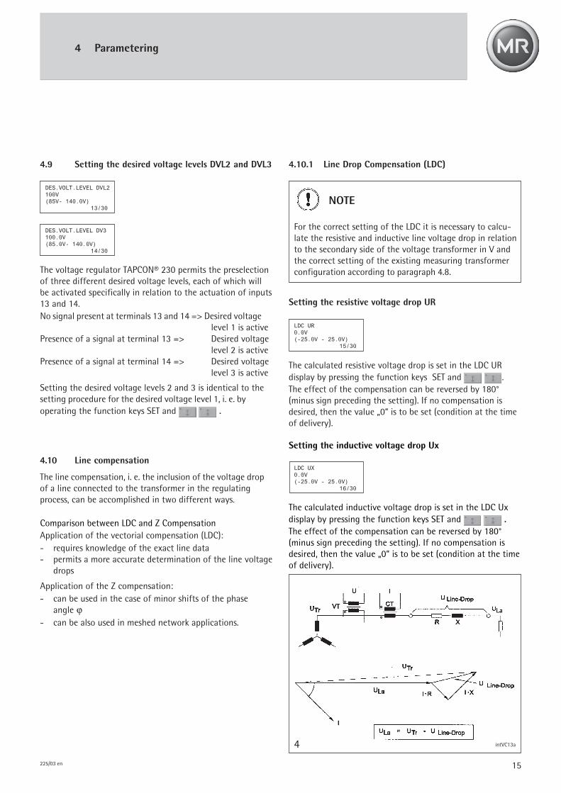
Setting the resistive voltage drop UR
The calculated resistive voltage drop is set in the LDC URdisplay by pressing the function keys SET and .The effect of the compensation can be reversed by 180°(minus sign preceding the setting). If no compensation isdesired, then the value „0“ is to be set (condition at the timeof delivery).
NOTE
For the correct setting of the LDC it is necessary to calcu-late the resistive and inductive line voltage drop in relationto the secondary side of the voltage transformer in V andthe correct setting of the existing measuring transformerconfiguration according to paragraph 4.8.
Setting the inductive voltage drop Ux
The calculated inductive voltage drop is set in the LDC Uxdisplay by pressing the function keys SET and .The effect of the compensation can be reversed by 180°(minus sign preceding the setting). If no compensation isdesired, then the value „0“ is to be set (condition at the timeof delivery).
DES.VOLT.LEVEL DVL2100V(85V- 140.0V)
13/30
DES.VOLT.LEVEL DV3100.0V(85.0V- 140.0V)
14/30
LDC UR0.0V(-25.0V - 25.0V)
15/30
LDC UX0.0V(-25.0V - 25.0V)
16/30
16 225/03 en
4.10.2 Z-Compensation
For correct setting of the parameters the voltage rise (ΔU)has to be calculated in consideration of the current.
Calculation of the required setting values:
Setting the limitation for ΔUmax (LIMIT)
The value is set by pressing the function keys SET and . If compensation is set to a certain value whileavoidance of excessive transformer voltage rises (e. g. in caseof an unusually high load) is desired, the limit values can beset to the desired voltage level.If no compensation is desired, the value „0“ is to be set.
Setting the voltage rise (VOLTRISE)
The calculated percentage of the voltage rise, referred to thedesired voltage level, is set by pressing the function keys SETand . If no compensation is desired, the value „0“ isto be set (link with →LIMIT).
4.11 Analog remote position indication (option)
Optionally, the voltage regulator TAPCON® 230 is availablewith an analog control/activation of the remote positionindication. This option requires an analog module.The following analog values can be processed:
• 4 – 20 mA• Potentiometer range with a minimum total resistance of
50 Ω , up to a maximum total resistance of 2 kΩ .
Press the SET and function keys to set therespective minimum and maximum positions.For POS MIN, please enter the position corresponding to e. g.4mA; for POS MAX, please enter the position correspondingto e. g. 20mA.The analog position indication will be included automaticallyif the TAPCON® 230 is equipped with the parallel operationoption.
Calculation of the required setting values:
UTr - ULoad IN . RCTΔU (%) = = = = = 100 • •
ULoad I
ΔU = Setting of Z-Compensation in %
UTr = Transformer voltage at current I
ULa = Line end voltage at current I and with the sameservice position of the tap-changer
I = Load current in A
IN = Rated current in A of the selected current trans-former connection to the voltage regulator,i. e. 0.2 A or 1 A or 5 A
RCT = Current transformer ratio, e. g. 200 A / 5 A
If the active voltage drops Ur and reactive voltage drops Uxare set correctly, then the line end voltage will remainconstant regardless of load.
Ur = IN . RCT . r . L (V) RVT
Ux = IN . RCT
. x . L (V) RVT
Where
Ur = LDC setting for resistive line voltage drop in V
Ux = LDC setting for inductive line voltage drop in V
IN = Rated current in A of the selected current trans-former connection to the voltage regulator,i.e. 0.2 A or 1 A or 5 A
RCT = Current transformer ratio, e. g. 200 A/ 5 A
RVT = Voltage transformer ratio, e. g.
30000 V /√ 3
100 V
r = Ohmic resistance of line in Ω/ km per phasex = Inductive reactance of line in Ω / km per phaseL = Length of line in km
4 Parametering
Z-COMP VOLTRISE0.0%(0.0% - 15.0%)
17/30
Z-COMP LIMIT0.0%(0%- 15.0%)
18/30
POS MIN1(-35 – 35)
20/30
POS MAX35(-35 – 35)
21/30
17225/03 en
4 Parametering
4.12 Voltage regulator identification
The voltage regulator contains a parametering interface toallow parametering via laptop. The required visualizationsoftware is included in the standard scope of delivery.The purpose of voltage regulator identifier is to assign aspecific ‘address’ to the individual voltage regulator topermit specified operation via visualization software.A number ranging between 0 and 9999 can be entered toserve as a „name“ by operating the SET and function keys.
4.14 Selection of the display in the 4th line ofthe display
The basic display of the voltage regulator TAPCON® 230 showsan additional measuring value in the 4th line. This measuringvalue can be set individually by operating the SET and
function keys.
The following measuring values are available:
- Current I
- Apparent power S
- Reactive power Q
- Active power P
- Phase angle PHI
- Power factor cos PHI
- Frequency f
- Status line
- Position, optional
4.13 Setting the unit to V or kV
The voltage regulator TAPCON® 230 allows the user to bothdisplay and enter the unit of the actual voltage level and thedesired voltage level in the basic display as well as the para-metering displays for the‚ desired voltage level 1, 2 and 3’ inthe primary voltage transformer unit kV.To that end it is indispensable that the rated voltage of thevoltage transformer be entered as indicated under paragraph4.8. Set the desired unit by operating the SET and function keys.
4.15 Language selection
The screen texts are available in two languages. Select thedesired language by operating the SET and function key.
VOLT.REG.IDENTIFIER1111(0- 9999)
26/30
DISPLAY V/kVkV(V/ kV)
28/30
SELECTION 4th LINECURRENT I(I,S,Q,P,PHI,..)
29/30
LANGUAGEGERMANGER/GB/F/E
30/30
18 225/03 en
5 Commissioning
5.1 Installation
The voltage regulator is suitable for both flush and projectedpanel mounting (see dimension diagram). Be sure to installthe device in an easily accessible place in the control room orin a switching cabinet attached to the transformer.
5.2 Connection
The voltage regulator is to be connected in accordance withthe wiring diagram (see Appendix).When connecting the equipment, please pay attention to:– the correct phase angle of the secondary terminals of
current transformer and potential transformer– correct connection of the output relays to the motor
drive unit– correct connection to earth of the housing.
The voltage regulator is normally fed by the voltage trans-former.
Connect the voltage transformer to terminals 1 and 2, andthe auxiliary voltage to terminals 3 and 4 (see fig. 5).
The TAPCON® 230 is optionally available with a supply inputof AC 230 V preset at the factory.
WARNING
Take care to properly connect the voltage regulator andthe housing to ground. Danger to life.
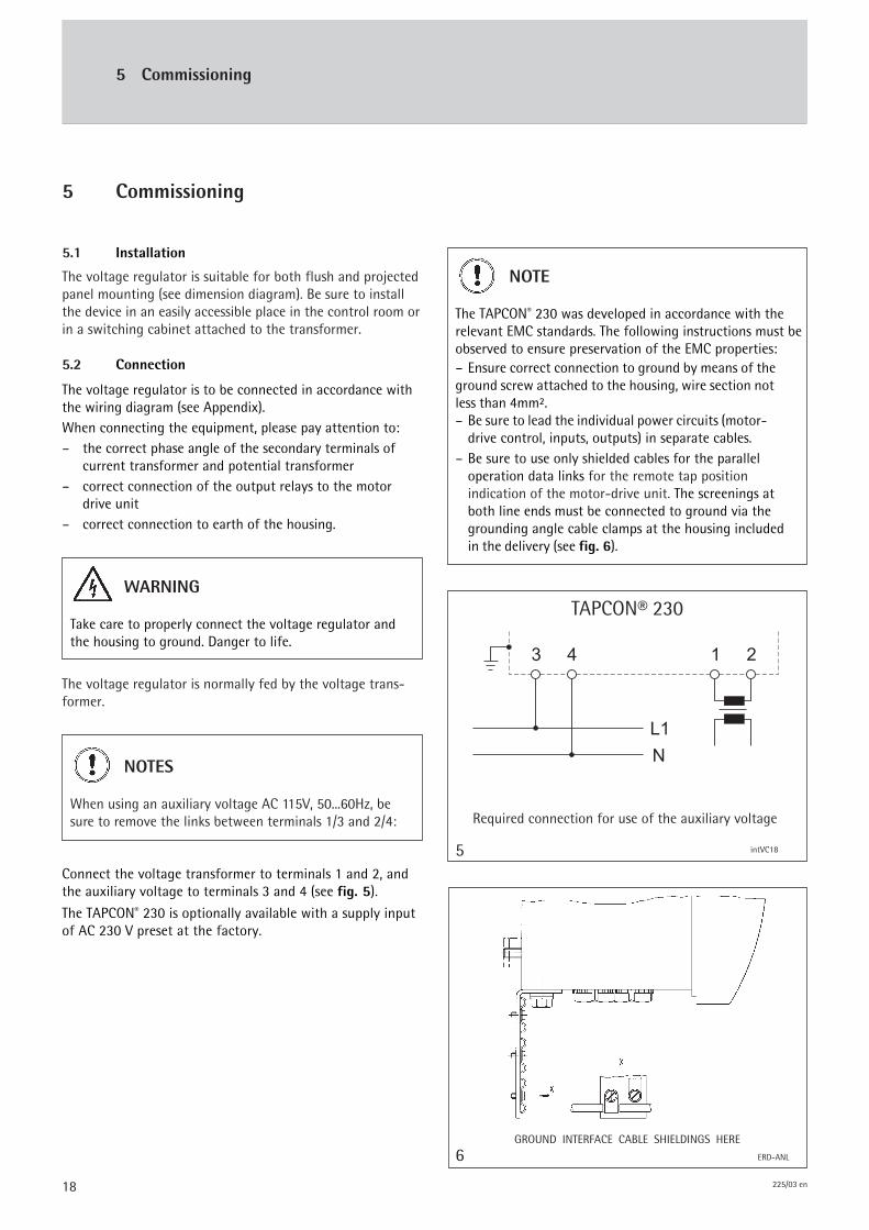
GROUND INTERFACE CABLE SHIELDINGS HERE
ERD-ANL6
NOTES
When using an auxiliary voltage AC 115V, 50...60Hz, besure to remove the links between terminals 1/3 and 2/4:
NOTE
The TAPCON® 230 was developed in accordance with therelevant EMC standards. The following instructions must beobserved to ensure preservation of the EMC properties:– Ensure correct connection to ground by means of theground screw attached to the housing, wire section notless than 4mm².– Be sure to lead the individual power circuits (motor-
drive control, inputs, outputs) in separate cables.– Be sure to use only shielded cables for the parallel
operation data links for the remote tap positionindication of the motor-drive unit. The screenings atboth line ends must be connected to ground via thegrounding angle cable clamps at the housing includedin the delivery (see fig. 6).
intVC18
TAPCON® 230
Required connection for use of the auxiliary voltage
5
5 Commissioning

19225/03 en
5 Commissioning
5.3 Easy setting of operating modes with NORMSET
Prior to commissioning, be sure to check the entire circuityand the measuring and operating voltage. To assess theworking mode of the voltage regulator, the use of a regis-tering device to record the regulator voltage (actual voltagelevel) is highly recommended.The related transformer should be subject to normal load.
a) Select the MANUAL operating mode at TAPCON® 230.
b) Select the NORMSET function as indicated under 4.1.
c) Set the Desired Voltage Level 1 as indicated under 4.2.
If you do not require a voltage display of the primary voltagein kV you may now proceed to initiate the regulator byoperating the AUTO function key.If you do require a voltage display in kV, however, pleaseproceed as follows:
d) Set the rated transformer voltage and the ratedtransformer current as indicated under 4.8.
If you wish to configure the TAPCON® 230 voltage regulatorto suit your specific requirements, please proceed asindicated under 5.4.
5.4 Function tests; operational settings
Prior to commissioning, be sure to check the entire circuityand the measuring and operating voltage. To assess theworking mode of the voltage regulator, the use of aregistering device to record the regulator voltage (actualvoltage level) is highly recommended. The related transfor-mer should be subject to normal load.
a) Select the MANUAL operating mode at TAPCON® 230
b) Set the transformation ratios of the transformers asspecified under paragraph 4.8, as well as the measuringcircuit.
c) Let the measured actual voltage (= voltage from thevoltage transformer) be indicated on the display of thevoltage regulator.
d) Let the current, power, and phase angle values beindicated on the display and compare these values withthose from possibly existing service measuringinstruments. If wrong signs are indicated, reverse thepolarity of the current or voltage transformer.
e) Set the desired voltage level. By manual control of themotor-drive, bring the on-load tap-changer to the serviceposition so that the desired voltage level is obtained(see paragraph 5.5).
f) Set the VOLTAGE LEVEL to this value.
g) Set the bandwidth "ΔU max“ to 1.0 %. In most cases thevoltage regulator is now in a balanced state (no presignalLED lamp lights up). Otherwise change the desired voltagelevel in steps of 0.5 V until a balanced state is reached.
h) Set the bandwidth „ΔU max“ dependently of the stepvoltage (see paragraph 4.3).
i) Set the delay time T1 to 20 s lin. as per paragraph 4.4;by manual control, move the on-load tap-changertowards "Raise" (arrow in the display right "–>") by onestep, the presignal LED lamp for "Lower“ (arrow in thedisplay left "–>") must come on. Set the mode of opera-tion to "AUTO"; 20 s after the presignal lamp lights up,the voltage regulator must control the on-load tap-changer back to its previous service position. The pre-signal LED lamp goes out. Set the mode of operation to"MANUAL". Repeat the control procedure towards"Lower".
Set the operating delay time T2 to 10 s. Set the mode ofoperation to "MANUAL". By manual control, move theon-load tap-changer towards "Raise" by two steps, thepre-signal LED lamp for "Lower" must come on.
Set the mode of operation to "AUTO", then 20 s after thepresignal lamp has come on, the voltage regulator mustautomatically control the on-load tap-changer back toits previous service position by one step and after further10 s by another step.
Set the delay times T1 and T2 to the desired value. If T2 isnot utilized, the "OFF" setting will be required.
When putting the transformer into service, it is recom-mended to set the delay time T1 provisionally to 100 s.Depending on the existing operating conditions, you maywant to determine the definitive setting only after sometime of observation. For this purpose it is recommendedto register the variation of the actual voltage and thenumber of tap change operations on a day-to-day basis.If an inverse response of the voltage regulator is desired,set an integral time response for the delay time 1. In thiscase the delay time is automatically shortened inverselyproportional to the deviation.j) a
20 225/03 en
5 Commissioning
k) Set the response threshold for undervoltage blockingU < to 85 %. Set the mode of operation to "MANUAL“and set the existing voltage level, e. g. 110 V, to 110 V /0.85 ≈ 130 V, so that the actual voltage now correspondsto the set percentage of the response threshold for theblocking value. The presignal LED lamp for "Raise“ mustlight up. Set the mode of operation switch to "AUTO“.After approx.10 s the signalling relay "U <" must beenergized, the signalling contact (Contacts 17/18/19) willopen; the output relay "Raise" must not issue a controlcommand. LED U < will now respond. Upon completion ofthis func-tion test you may now set the desired responsethreshold for undervoltage blocking.
l) Set the response threshold for overvoltage detection U> to115 %. Set the mode of operation to "MANUAL", e. g. 110V to 110 V / 1.15 ≈ 95 V so that the actual voltage nowcorresponds to the set percentage of the responsethreshold for overvoltage detection. The presignal LEDlamp for "Lower" must light up. Set the mode of operationto "AUTO".The output relay "Lower" must issue periodic controlcommands at 1.5 s intervals. The group signalling contact17/18/19 will close/open. LED U > will now respond.Now set the desired response threshold for overvoltagedetection to the initially desired voltage level.
m) Set the response threshold for overcurrent blocking I >.A function check is not necessary.
n) Setting the load drop LDC (as per paragraph 4.10.1). Setthe mode of operation to "MANUAL".Settings for Ux = Ur = 0, no presignal LED lamp for Raise/Lower must light up.Setting of Ur = 20 V, Ux = 0 V, the presignal LED lamp for"Raise" must light up.Setting of Ur = -20 V, Ux = 0 V, the presignal LED lamp for"Lower" must light up (during this function check aminimum load current of 5 % of the rated current of thecurrent transformer must flow.)If the presignals appear in opposite direction, change thepolarity of the current transformer.The actually desired LDC can be set upon completion of theabove settings.Set the mode of operation to AUTO.Check if the setting is correct by observing the voltage atthe line end during service and with different loads. Whenthe setting is correct the voltage at the line end will remainconstant.
o) Setting of Z Compensation (as per paragraph 4.10.2) as analternative to LDC.
Set the mode of operation to MANUAL.
Set the voltage rise to 0, the voltage regulator is in abalanced state, no presignal LED lamp must light up.
Set the voltage rise to 15 %, the presignal LED lamp for"Raise" must light up (during this functional check a loadcurrent of 10 % of the rated current of the currenttransformer must flow).
The desired values for Z Compensation can be set uponcompletion of the above settings.
Set the mode of operation to AUTO. Check if the settingis correct by observing the voltage at a specific point inthe line and with different loads. When the setting iscorrect the voltage at the line end will remain constant.
p) Set the DESIRED VOLTAGE LEVEL 2 to the desired value(refer to paragraph 4.9). Set the mode of operation toMANUAL and connect L+ to terminal 13. According tothe set value for Desired Voltage Level 2, the presignal"Lower" or "Raise" must respond.
Please proceed in the same manner for DESIRED VOLTAGELEVEL 3 by connecting L+ to to terminal 14 signallingrelay for DESIRED VOLTAGE LEVEL 3. Set the mode ofoperation to AUTO.
5.5 Manual control of the on-load tap-changer
The manual control of the on-load-tap-changer is possible ifthe buttons "hand“ and lower resp. raise or direction "raise"resp. "lower" are pushed at same time.
21225/03 en
6 Parallel operation without system topology (Option)
NOTE
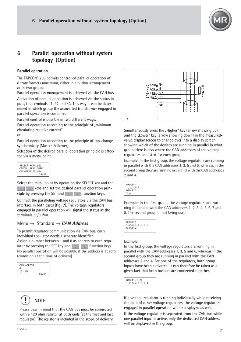
Please bear in mind that the CAN bus must be connectedwith a 120 ohm resistor at both ends (at the first and lastregulator). The resistor is included in the scope of delivery.
7
Simultaneously press the „Higher“ key (arrow showing up)and the „Lower“ key (arrow showing down) in the measured-value display screen to change over into a display screenshowing which of the devices are running in parallel in whatgroup. Here is also where the CAN addresses of the voltageregulators are listed for each group.Example: In the first group, the voltage regulators are runningin parallel with the CAN addresses 1, 3, 5 and 6, whereas in thesecond group they are running in parallel with the CAN addresses2 and 4.
GROUP 11,2,3,5,6GROUP 22,4
Example:In the first group, the voltage regulators are running inparallel with the CAN addresses 1, 3, 5 and 6, whereas in thesecond group they are running in parallel with the CANaddresses 2 and 4. For one of the regulators, both groupinputs have been activated. It can therefore be taken as agiven fact that both busbars are connected together.
GROUP 11,2,3,4,5,6,7,8GROUP 2
GROUP (1+2)1,2,3,4,5,6,2,4
Parallel operation
The TAPCON® 230 permits controlled parallel operation of8 transformers maximum, either in a busbar arrangementor in two groups.Parallel operation management is achieved via the CAN bus.
Activation of parallel operation is achieved via the status in-puts, the terminals 41, 42 and 43. This way it can be deter-mined in which group the associated transformer engaged inparallel operation is contained.
Parallel control is possible in two different ways:Parallel operation according to the principle of „minimumcirculating reactive current“or
Parallel operation according to the principle of tap-changesynchronicity (Master-Follower).Selection of the desired parallel operation principle is effec-ted via a menu point.
Select the menu point by operating the SELECT key and the keys and set the desired parallel operation prin-
ciple by pressing the SET and function keys.
Connect the paralleling voltage regulators via the CAN businterface in both cases (fig. 7). The voltage regulatorsengaged in parallel operation will signal the status at theterminals 38/39/40.
6 Parallel operation without systemtopology (Option)
Menu → Standard → CAN AddressTo permit regulator communication via CAN bus, eachindividual regulator needs a separate identifier.Assign a number between 1 and 8 as address to each regu-lator by pressing the SET key and function keys.No parallel operation will be possible if the address is at zero(condition at the time of delivery).
SELECT PARALLELCIRCUL.REAC.CURR.CRC/MAST/FOLLOW
19/30
CAN ADRESS0(1- 8)
25/30
If a voltage regulator is running individually while receivingthe data of other voltage regulators, the voltage regulatorsengaged in parallel operation will be displayed as well.
If the voltage regulator is separated from the CAN bus whileone parallel input is active, only the dedicated CAN addresswill be displayed in the group.
Example: In the first group, the voltage regulators are run-ning in parallel with the CAN addresses 1, 2, 3, 4, 5, 6, 7 and8. The second group in not being used.
22 225/03 en
6 Parallel operation without system topology (Option)
Example:If the CAN bus is disconnected, a "CAN BUS ERROR" will bedisplayed in the status line.
GROUP 11GROUP 2
No voltage regulator will be displayed in the group eitherduring individual operation with disconnected CAN bus or inthe absence of Can telegrams during individual operation.
GROUP 1
GROUP 2
6.1.1 System configuration, settings
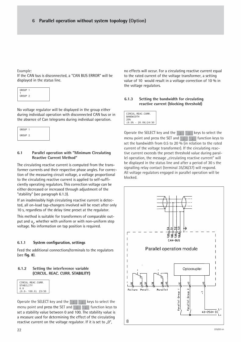
Feed the additional connections/terminals to the regulators(see fig. 8).
6.1 Parallel operation with "Minimum CirculatingReactive Current Method“
The circulating reactive current is computed from the trans-former currents and their respective phase angles. For correc-tion of the measuring circuit voltage, a voltage proportionalto the circulating reactive current is applied to self-suffi-ciently operating regulators. This correction voltage can beeither decreased or increased through adjustment of the"stability" (see paragraph 6.1.3).
If an inadmissibly high circulating reactive current is detec-ted, all on-load tap-changers involved will be reset after only10 s, regardless of the delay time preset at the regulator.
This method is suitable for transformers of comparable out-put and uk, whether with uniform or with non-uniform stepvoltage. No information on tap position is required.
Operate the SELECT key and the keys to select themenu point and press the SET and function keys toset the bandwidth from 0.5 to 20 % (in relation to the ratedcurrent of the voltage transformer). If the circulating reac-tive current exceeds the preset threshold value during paral-lel operation, the message „circulating reactive current“ willbe displayed in the status line and after a period of 30 s thesignalling relay contact (terminal 35/36/37) will respond.All voltage regulators engaged in parallel operation will beblocked.
6.1.3 Setting the bandwidth for circulatingreactive current (blocking threshold)
8
6.1.2 Setting the interference variable(CIRCUL. REAC. CURR. STABILITY)
CIRCUL.REAC.CURR.STABILITY0.0(0.0- 100.0) 23/30
Operate the SELECT key and the keys to select themenu point and press the SET and function keys toset a stability value between 0 and 100. The stability value isa measure used for determining the effect of the circulatingreactive current on the voltage regulator. If it is set to „0“,
no effects will occur. For a circulating reactive current equalto the rated current of the voltage transformer, a settingvalue of 10 would result in a voltage correction of 10 % inthe voltage regulators.
CIRCUL.REAC.CURR.BANDWIDTH20%(0.5% - 20.0%)24/30
23225/03 en
6 Parallel operation without system topology (Option)
6.1.4 Function tests, commissioning
6.1.4.1 Preliminary settings
The current transformer inputs must be connected and thetransformer configuration must be parameterised correctly.The voltage regulators must be set to identical operatingparameters for the desired voltage, bandwidth, time delay 1,and line compensation, if applicable (LDC or Z Compensation,respectively).In all cases, set STABILITY to "0“ and Blocking to "20“.During parallel operation, time delay 2 must never be setbelow 8 s!All settings must be performed in the "Manual“ operatingmode.
6.1.4.2 Setting the interference variable(CIRCUL. REAC. CURR. STABILITY)
Individually set both transformers to identical voltage withthe on-load tap-changers so that both voltage regulators arein a balanced state (no presignal LED are lighting up, theindication of "dU %" must be as low as possible, i. e. lowerthan the preset bandwidth "dU max").
Now switch the transformers to parallel operation and enableparallel control (close contact at terminals 41 and 42, respec-tively).The voltage regulators must continue to remain in a balancedstate, the LED lamp "parallel operation" on the front panel islighting up.Raise one of the two transformers by one voltage step andlower the other of the two transformers by one voltage step.Both regulators must continue to remain in a balanced state.Raise the setting value "CIRC.REAC.CURR.STABILITY" of bothregulators in small steps starting with "0" until the corres-ponding presignals appear (the regulator of the transformerwith the higher voltage step must show the tendency "lower"while the other transformer must show the tendency "raise“).Now add the setting values thus established and set theadded-up value for both regulators.Select the "Auto" operating mode for both voltage regula-tors. Both voltage regulators must control the on-load tap-changers back into their previous service positions.The presignals will go out.
NOTE
The prerequisite for the proper functioning of paralleloperation is the commissioning of the voltage regulatorsfor individual operation.
6.1.4.3 Setting the circulating reactive currentmonitoring (CIRCUL. REAC. CURR. MON.BANDWIDTH)
Switch over one of the two voltage regulators to the"Manual“ operating mode. Using the manual control, theassociated motor drive must now be reset to "Raise“ by themaximum admissible difference of the service positionsbetween the parallel operating transformers (e. g. by 1 … 2steps).Starting with the preset value of "20 %", reset the blockingtowards a lower value in small steps until the message"Circulating reactive current" appears in the status line of thedisplay (please wait 2 – 3 s between the individual steps).The bandwidth threshold of the circulating reactive currentmonitoring is reached as soon as this message appears.The voltage regulators will block all further regulating actionsand the signalling relay will respond (terminals 35/36/37).Now reset the blocking again towards a higher value untilthe message „circulating reactive current“ disappears fromthe status line of the display.
Again switch the voltage regulator back to the "Auto"operating mode. The motor-drive will be automaticallycontrolled back to the original service position.Use the value established for the "Blocking" threshold to setit for all of the other regulators.
6.2 Parallel operation according to synchro-nized tap-change operation Master/Follower
This method is suitable for transformers featuring an identi-cal rated current, identical step voltage, and an identicalnumber of service positions. The motor-drive must signal thetap-change position by means of a current of 4 … 20 mA(with 4 mA corresponding to the lowest position and 20 mAcorresponding to the highest position). Optionally the con-nection of a potentiometer contact range in the motor-driveis possible in lieu of the injected current.
During parallel operation, actual voltage regulation is per-formed by one of the voltage regulators (Master function).The second voltage regulator (Follower) receives the tap-change position of the motor-drive from the first regulator,for comparison with the tap-change position of its ownmotor drive. If a difference is noted, the motor-drive inquestion will receive a suitable control pulse.
If the previous service position cannot be achieved that way,the "CIRC.REAC.CURR. STABILITY“ setting needs to be in-creased. If the on-load tap-changers are regulating out ofsync ("pumping“), this setting needs to be reduced.
24 225/03 en
6.2.1 System configuration, settings, transfer ofthe on-load tap-changer setting
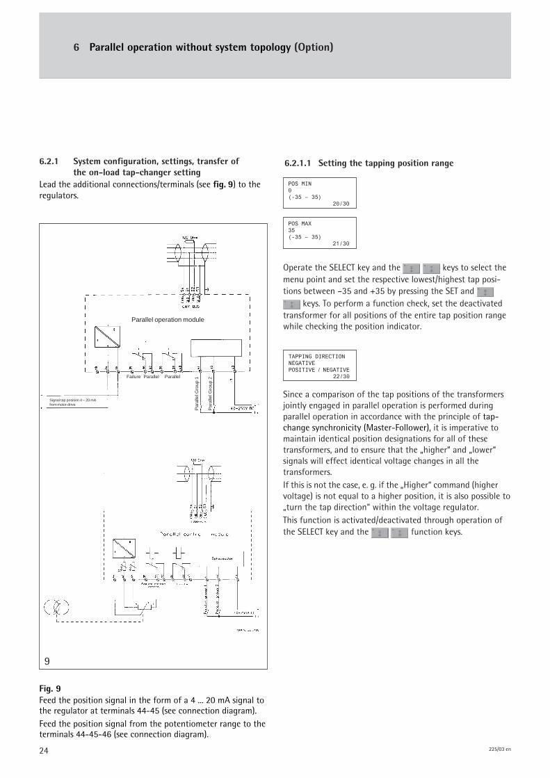
Lead the additional connections/terminals (see fig. 9) to theregulators.
6.2.1.1 Setting the tapping position range
Operate the SELECT key and the keys to select themenu point and set the respective lowest/highest tap posi-tions between –35 and +35 by pressing the SET and
keys. To perform a function check, set the deactivatedtransformer for all positions of the entire tap position rangewhile checking the position indicator.
Since a comparison of the tap positions of the transformersjointly engaged in parallel operation is performed duringparallel operation in accordance with the principle of tap-change synchronicity (Master-Follower), it is imperative tomaintain identical position designations for all of thesetransformers, and to ensure that the „higher“ and „lower“signals will effect identical voltage changes in all thetransformers.If this is not the case, e. g. if the „Higher“ command (highervoltage) is not equal to a higher position, it is also possible to„turn the tap direction“ within the voltage regulator.This function is activated/deactivated through operation ofthe SELECT key and the function keys.
POS MIN0(-35 – 35)
20/30
POS MAX35(-35 – 35)
21/30
9
Fig. 9Feed the position signal in the form of a 4 ... 20 mA signal tothe regulator at terminals 44-45 (see connection diagram).Feed the position signal from the potentiometer range to theterminals 44-45-46 (see connection diagram).
6 Parallel operation without system topology (Option)
Parallel operation module
Failure Parallel Parallel
Par
alle
l Gro
up 1
Par
alle
l Gro
up 2
Signal tap position 4 – 20 mAfrom motor-drive
TAPPING DIRECTIONNEGATIVEPOSITIVE / NEGATIVE
22/30
25225/03 en
6 Parallel operation without system topology (Option)
6.2.2 Function tests, commissioning andpreliminary settings
The voltage regulators must be set to identical operatingparameters for the desired voltage, bandwidth, time delay 1,and line compensation, if applicable.The tap position indication at the regulators must functioncorrectly.Select the "MANUAL“ operating mode at the voltageregulators.Individually set all on-load tap-changers involved in paralleloperation to identical voltage so that the voltage regulatorsare in a balanced state (no presignal appearing on the dis-play).Now switch the transformers to parallel operation and closethe contacts at terminals 41 and 42, respectively. The voltageregulators must continue to remain in a balanced state andthe LED lamps "Parallel“ at the regulators must respond.Switch the Follower voltage regulator to the "AUTO“operating mode.Use the manual control to raise the MASTER regulating unitengaged in the "MANUAL“ operating mode by one step; thefollower regulator now has to automatically drag along theassociated transformer to do the same.
During the short period while a tap position difference ispresent, the message "TAP DIFFERENCE“ will appear in thestatus line of the display. If a follower regulator fails to dragalong its associated transformer, regulating action will beblocked and a signalling relay will respond (terminals 35/36/37).
6.2.1.2 Selecting the Master/Follower operation
NOTE
The trimming resistor R45 is located directly behind termi-nal 45 of the TAPCON® 230, whereas the trimming resistorR46 is located directly behind terminal 46, as shown onpages 30 and 31. Setting/trimming is done using theadjusting screws located on the visible side of the trimmingresistor housing. Please note that due to TAPCON® 230’smeasuring-cycle time being fixed, the trimming resistorsshould be operated slowly to allow for an update of thecurrent operating position on the TAPCON® 230’s display.
SELECT PARALLELCIRCUL.REAC.CURR.CRC/MAST/FOLLOW
19/30
Operate the SELECT key and the keys to select themenu point and assign the respective regulator as a Masteror a Follower by pressing the SET and keys.
If both regulators were assigned as „Follower“ or „Master“during parallel operation, the regulators will be blocked (seesection 6.3 – Disturbances during parallel operation).
NOTE
The prerequisite for the proper functioning of paralleloperation is the commissioning of the voltage regulatorsfor individual operation.
When using a potentiometer contact range (see section 4.11),it is advisable to first calibrate the top and bottom operatingpositions, if needed. To that end, start by indicating thebottom (POS MIN) and top (POS MAX) operating positions viathe parameter screens 20 and/or 21, as outlined above.Then proceed to calibrate the operating positions as follows:• Establish the connections in accordance with the
corresponding attached connection diagram.
• Move the OLTC into the operating position "2".
• Set the R45 trimming resistor at the TAPCON® 230 sothat the operating position "2" will appear in theTAPCON® 230’s display.
• Move the OLTC to the operating position „nmax-1“ (e. g.to the operating position "32" out of a total of 33 pos-sible OLTC operating positions).
• Set the R46 trimming resistor at the TAPCON® 230 sothat the operating position "nmax-1" will appear in theTAPCON® 230’s display.
• Since the trimming resistor settings are capable ofmutually influencing each other, the entire processshould be double-checked for safety reasons byrepeatedly making the OLTC approach the operatingposition "2" and checking the TAPCON® 230’s display.Should it turn out that another calibration procedure isnecessary, it is also advisable to recheck the operatingposition "nmax-1" and to recalibrate it, if needed.
26 225/03 en
6 Parallel operation without system topology (Option)
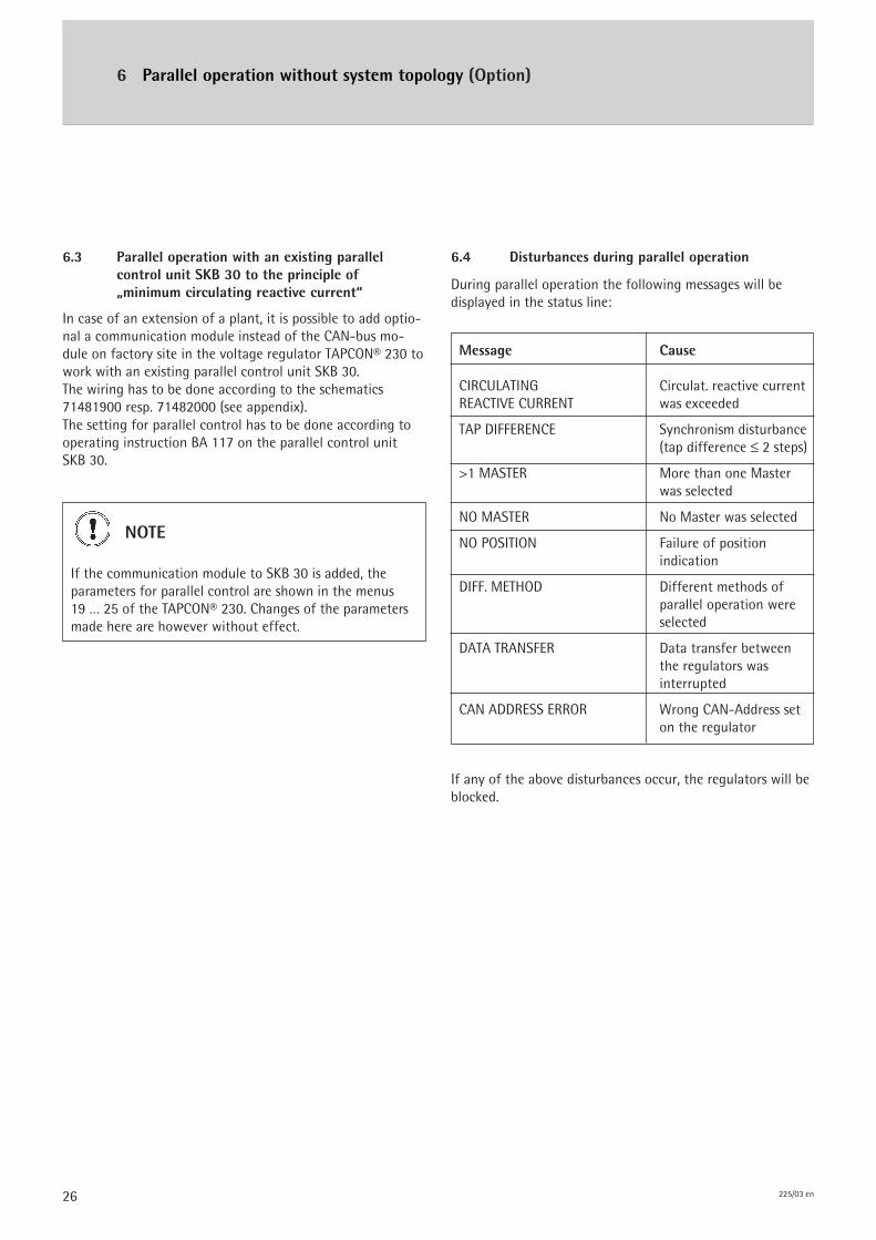
6.4 Disturbances during parallel operation
During parallel operation the following messages will bedisplayed in the status line:
Message Cause
CIRCULATING Circulat. reactive currentREACTIVE CURRENT was exceeded
TAP DIFFERENCE Synchronism disturbance(tap difference ≤ 2 steps)
>1 MASTER More than one Masterwas selected
NO MASTER No Master was selected
NO POSITION Failure of positionindication
DIFF. METHOD Different methods ofparallel operation wereselected
DATA TRANSFER Data transfer betweenthe regulators wasinterrupted
CAN ADDRESS ERROR Wrong CAN-Address seton the regulator
If any of the above disturbances occur, the regulators will beblocked.
6.3 Parallel operation with an existing parallelcontrol unit SKB 30 to the principle of„minimum circulating reactive current“
In case of an extension of a plant, it is possible to add optio-nal a communication module instead of the CAN-bus mo-dule on factory site in the voltage regulator TAPCON® 230 towork with an existing parallel control unit SKB 30.The wiring has to be done according to the schematics71481900 resp. 71482000 (see appendix).The setting for parallel control has to be done according tooperating instruction BA 117 on the parallel control unitSKB 30.
NOTE
If the communication module to SKB 30 is added, theparameters for parallel control are shown in the menus19 … 25 of the TAPCON® 230. Changes of the parametersmade here are however without effect.

27225/03 en
7 Appendix
Front view ............................................................................................................................................................................................. TC230_1
Control panel set-up and mounting ............................................................................................................................................. 899564
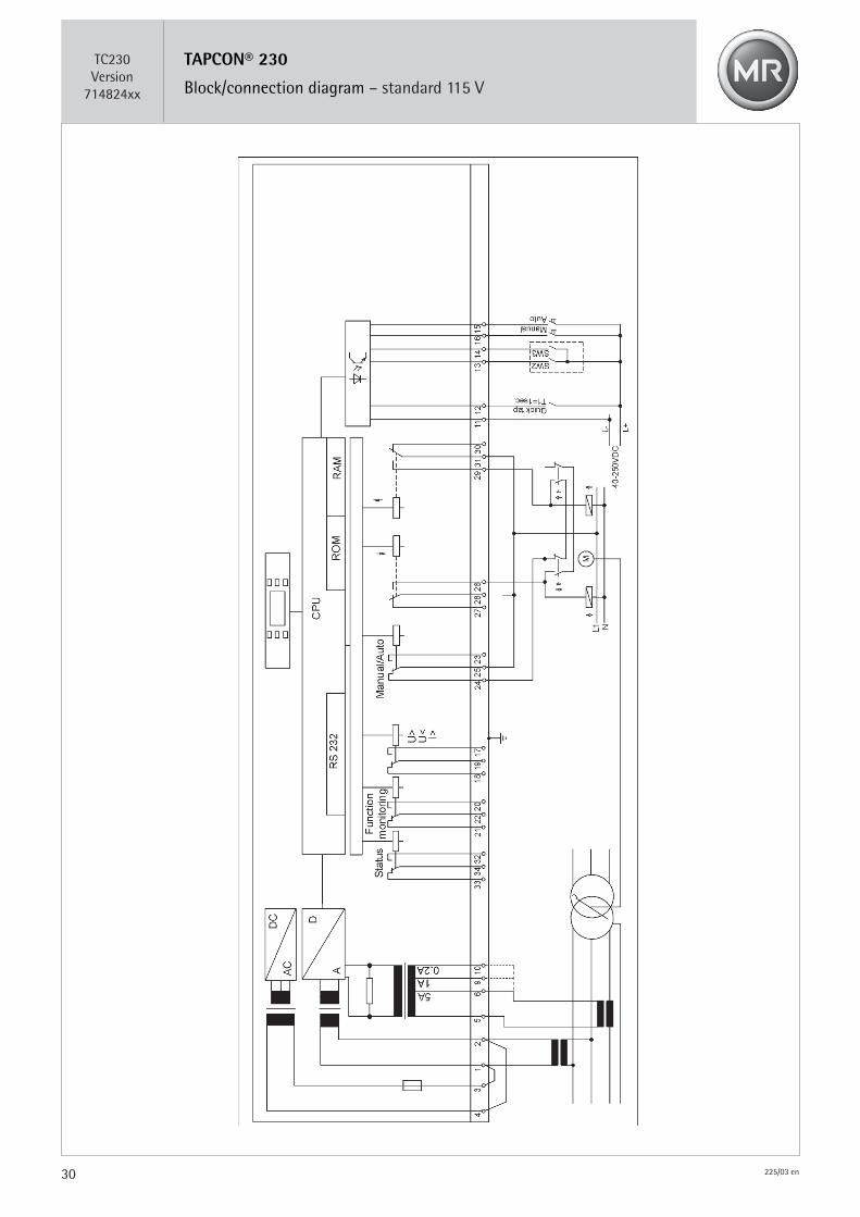
Block/connection diagram – standard 115 V ............................................................................................................................ TC230_714824xx
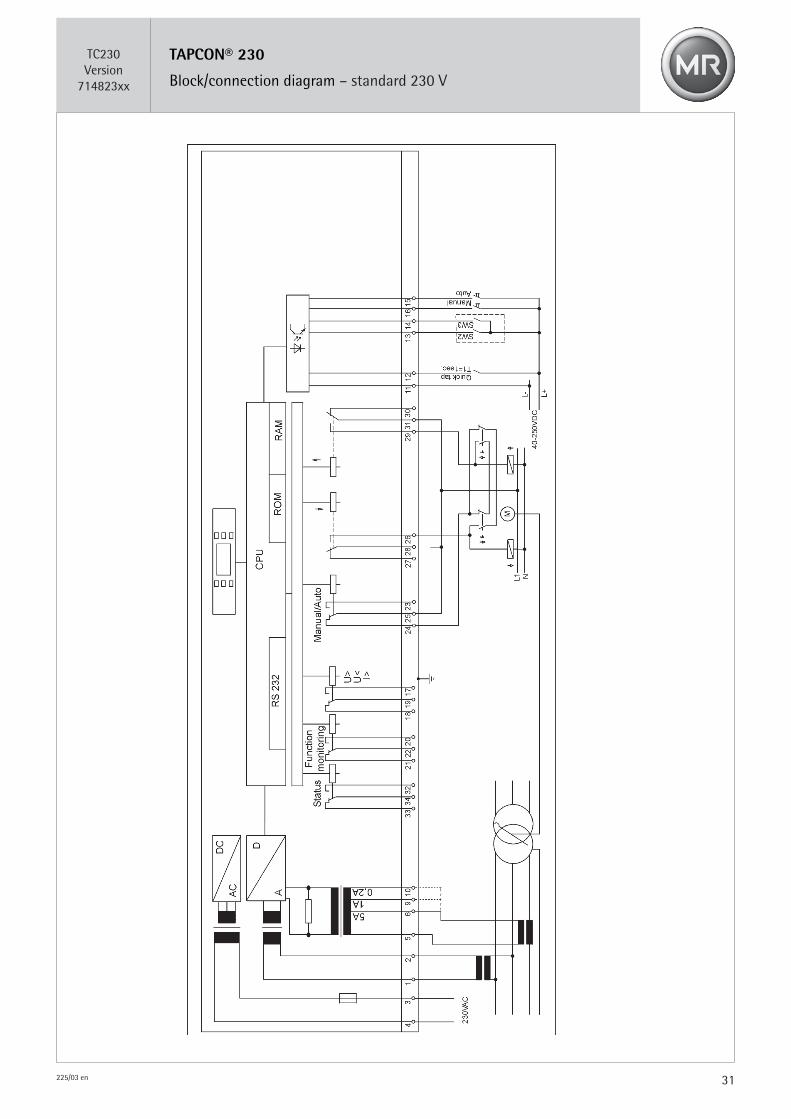
Block/connection diagram – Standard 230 V ............................................................................................................................ TC230_714823xx
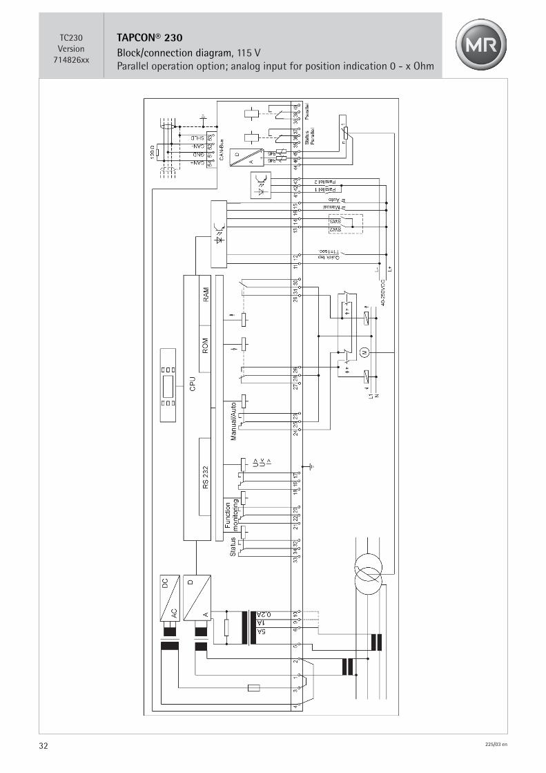
Block/connection diagram, 115 V, parallel operation option;analog input for position indication 0 - x Ohm ........................................................................................................................ TC230_714826xx
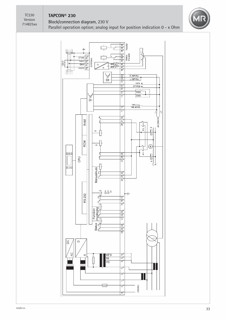
Block/connection diagram, 230 V, parallel operation option;analog input for position indication 0 - x Ohm ........................................................................................................................ TC230_714825xx
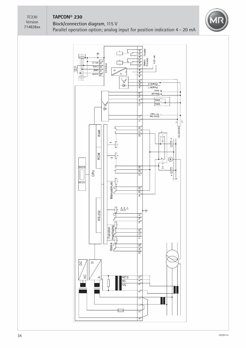
Block/connection diagram, 115 V, parallel operation option;analog input for position indication 4 - 20 mA ........................................................................................................................ TC230_714828xx
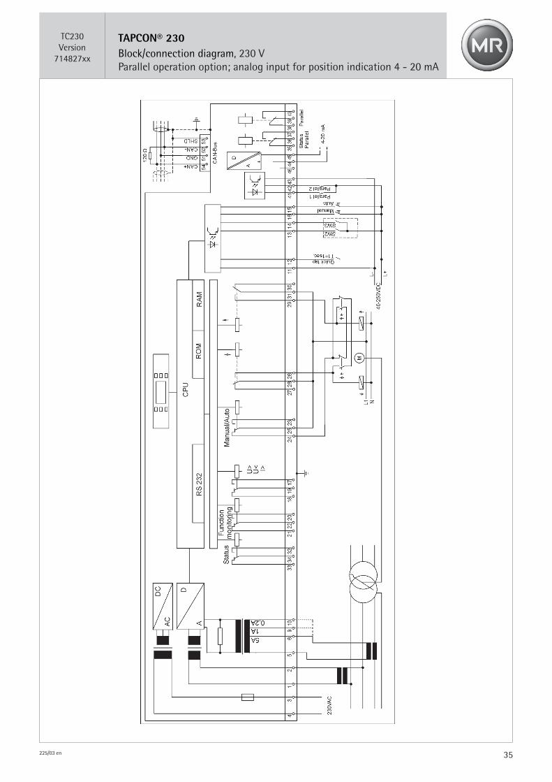
Block/connection diagram, 230 V, parallel operation option;analog input for position indication 4 - 20 mA ........................................................................................................................ TC230_714827xx
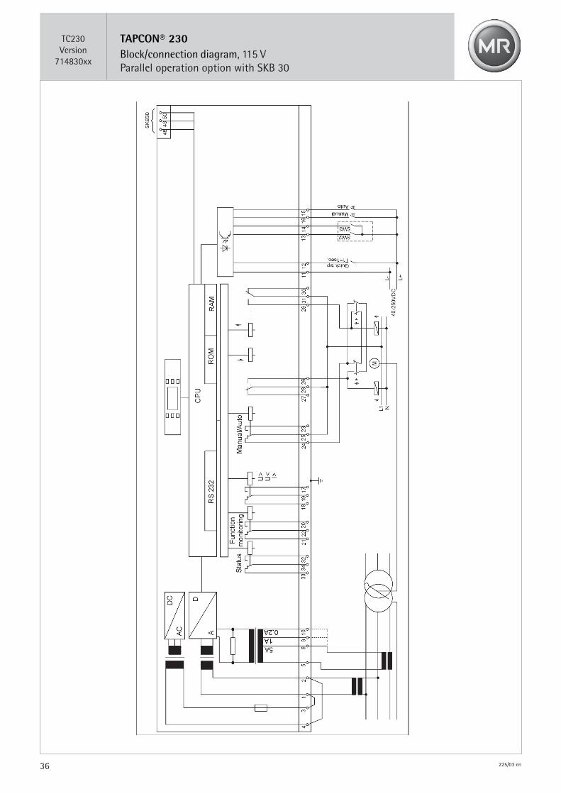
Block/connection diagram, 115 V, parallel operation option with SKB 30 ....................................................................... TC230_714830xx
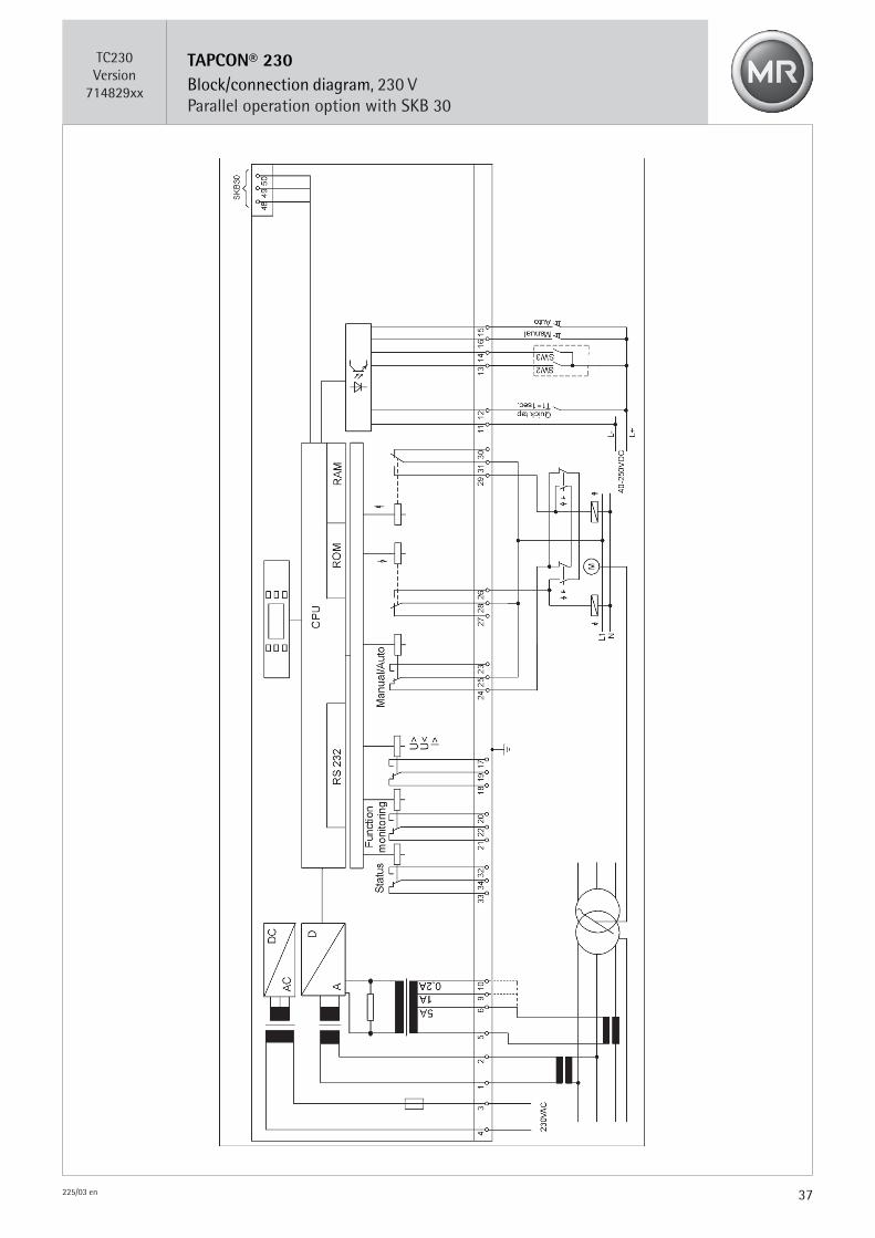
Block/connection diagram, 230 V, parallel operation option with SKB 30 ....................................................................... TC230_714829xx
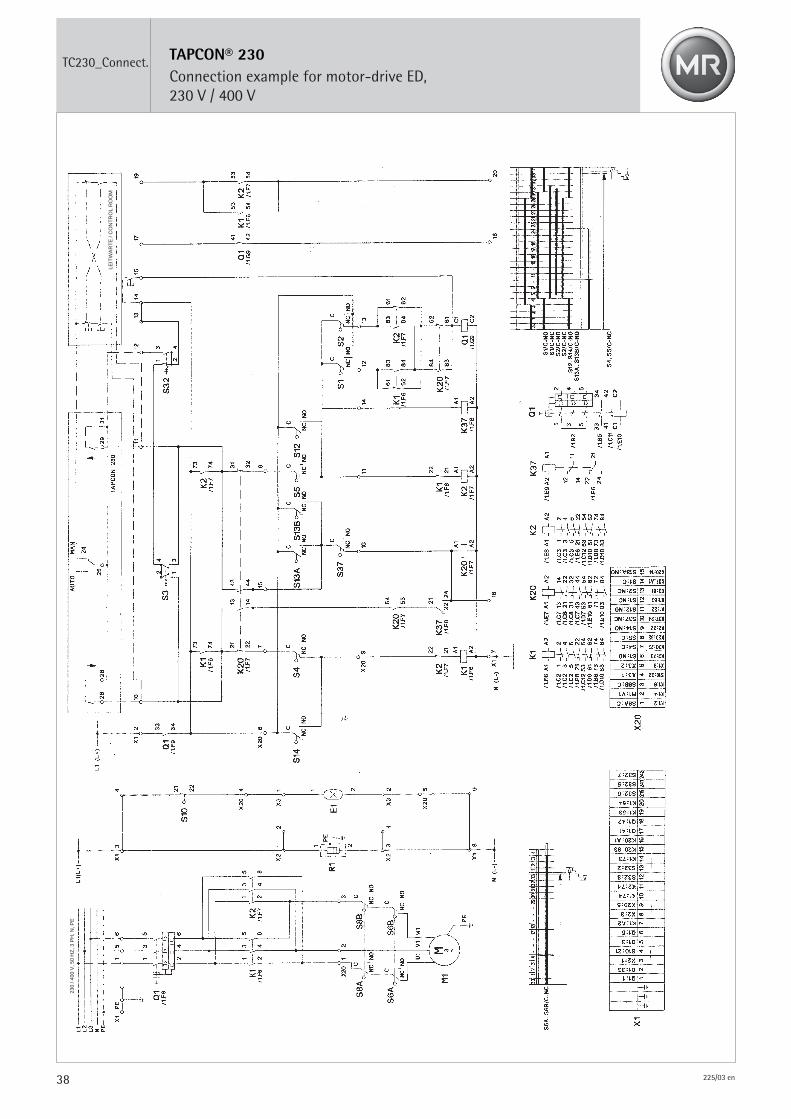
Block/connection diagram, connection example for motor-drive ED, 230 V / 400 V ................................................... TC230_Connect.
7 Appendix
28 225/03 en
TAPCON® 230Front view
TC230_1
29225/03 en
TAPCON® 230
Control panel set-up and mounting8995640E
Clamp forflush mounting
Remove crimp cable-entries for flushmounting
Bracketing fishplatefor panel mounting
Panel cutout forflush mounting
30 225/03 en
TAPCON® 230
Block/connection diagram – standard 115 V
TC230Version
714824xx
31225/03 en
TAPCON® 230
Block/connection diagram – standard 230 V
TC230Version
714823xx
32 225/03 en
TAPCON® 230Block/connection diagram, 115 VParallel operation option; analog input for position indication 0 - x Ohm
TC230Version
714826xx
33225/03 en
TAPCON® 230Block/connection diagram, 230 VParallel operation option; analog input for position indication 0 - x Ohm
TC230Version
714825xx
34 225/03 en
TAPCON® 230Block/connection diagram, 115 VParallel operation option; analog input for position indication 4 - 20 mA
TC230Version
714828xx
35225/03 en
TAPCON® 230Block/connection diagram, 230 VParallel operation option; analog input for position indication 4 - 20 mA
TC230Version
714827xx
36 225/03 en
TAPCON® 230Block/connection diagram, 115 VParallel operation option with SKB 30
TC230Version
714830xx
37225/03 en
TAPCON® 230Block/connection diagram, 230 VParallel operation option with SKB 30
TC230Version
714829xx
38 225/03 en
TAPCON® 230Connection example for motor-drive ED,230 V / 400 V
TC230_Connect.
LEIT
WA
RT
E /
CO
NT
RO
L R
OO
M
230
/ 400
V, 5
0 H
Z, 3
PH
, N, P
E


www.reinhausen.com
BA 225/03 en • 0909 • F0102202 • Printed in Germany
©Maschinenfabrik Reinhausen GmbH Phone (+49) 9 41/40 90-0Falkensteinstrasse 8 Fax (+49) 9 41/40 90-6 0093059 Regensburg, Germany E-mail [email protected]