Embed Size (px)
Citation preview

Voltage RegulatorTAPCON® 260
Operating Instructions
3643251/00 EN

© All rights reserved by Maschinenfabrik ReinhausenDissemination and reproduction of this document and use and disclosure of its content are strictly prohibitedunless expressly permitted.Infringements will result in liability for compensation. All rights reserved in the event of the granting of patents,utility models or designs.The product may have been altered since this document was published.We reserve the right to change the technical data, design and scope of supply.Generally the information provided and agreements made when processing the individual quotations and ordersare binding.The original operating instructions were written in German.
Table of contents
Maschinenfabrik Reinhausen 2014 33643251/00 EN TAPCON® 260
Table of contents
1 Introduction ......................................................................................................................... 91.1 Manufacturer ....................................................................................................................................... 9
1.2 Subject to change without notice......................................................................................................... 9
1.3 Completeness...................................................................................................................................... 9
1.4 Supporting documents......................................................................................................................... 9
1.5 Safekeeping....................................................................................................................................... 10
1.6 Notation conventions ......................................................................................................................... 101.6.1 Hazard communication system ........................................................................................................................... 10
1.6.2 Information system .............................................................................................................................................. 11
1.6.3 Instruction system ............................................................................................................................................... 11
1.6.4 Typographic conventions .................................................................................................................................... 12
2 Safety ................................................................................................................................. 132.1 General safety information ................................................................................................................ 13
2.2 Appropriate use ................................................................................................................................. 13
2.3 Inappropriate use............................................................................................................................... 13
2.4 Personnel qualification ...................................................................................................................... 14
2.5 Operator's duty of care ...................................................................................................................... 14
3 Product description .......................................................................................................... 153.1 Scope of delivery ............................................................................................................................... 15
3.2 Function description of the voltage regulation ................................................................................... 15
3.3 Operating modes ............................................................................................................................... 16
3.4 Hardware ........................................................................................................................................... 173.4.1 Operating controls ............................................................................................................................................... 17
3.4.2 Display elements ................................................................................................................................................. 19
3.4.3 Serial interface .................................................................................................................................................... 21
3.4.4 Assemblies .......................................................................................................................................................... 22
4 Packaging, transport and storage................................................................................... 234.1 Packaging.......................................................................................................................................... 234.1.1 Purpose ............................................................................................................................................................... 23
4.1.2 Suitability, structure and production ................................................................................................................... 23
4.1.3 Markings.............................................................................................................................................................. 23
4.2 Transportation, receipt and handling of shipments............................................................................ 23

Table of contents
Maschinenfabrik Reinhausen 20144 3643251/00 ENTAPCON® 260
4.3 Storage of shipments......................................................................................................................... 24
5 Mounting............................................................................................................................ 265.1 Preparation ........................................................................................................................................ 26
5.2 Mounting device ................................................................................................................................ 26
5.3 Connecting device ............................................................................................................................. 275.3.1 Cable recommendation ....................................................................................................................................... 27
5.3.2 Information about laying fiber-optic cable............................................................................................................ 29
5.3.3 Electromagnetic compatibility .............................................................................................................................. 29
5.3.4 Connecting cables to the system periphery ........................................................................................................ 33
5.3.5 Wiring device....................................................................................................................................................... 34
5.3.6 Checking functional reliability .............................................................................................................................. 34
6 Commissioning ................................................................................................................. 356.1 Setting the display contrast ............................................................................................................... 35
6.2 Setting parameters ............................................................................................................................ 356.2.1 Setting the language ........................................................................................................................................... 36
6.2.2 Setting date and time .......................................................................................................................................... 36
6.2.3 Setting further parameters................................................................................................................................... 37
7 Functions and settings..................................................................................................... 397.1 Key lock ............................................................................................................................................. 39
7.2 Carrying out tap-change operation manually..................................................................................... 39
7.3 General .............................................................................................................................................. 407.3.1 Setting device ID ................................................................................................................................................. 40
7.3.2 Setting the baud rate ........................................................................................................................................... 40
7.3.3 Setting the voltage display kV/V.......................................................................................................................... 41
7.3.4 Setting current display unit .................................................................................................................................. 41
7.3.5 Setting the switching pulse time .......................................................................................................................... 42
7.3.6 Dimming display .................................................................................................................................................. 44
7.3.7 Setting motor runtime monitoring ........................................................................................................................ 44
7.4 NORMset........................................................................................................................................... 46
7.5 Control parameters............................................................................................................................ 487.5.1 Setting desired value 1...3................................................................................................................................... 50
7.5.2 Bandwidth............................................................................................................................................................ 51
7.5.3 Setting delay time T1........................................................................................................................................... 53
7.5.4 Setting control response T1 ................................................................................................................................ 53
7.5.5 Setting delay time T2........................................................................................................................................... 54

Table of contents
Maschinenfabrik Reinhausen 2014 53643251/00 EN TAPCON® 260
7.6 Regulation behavior if negative power flow ....................................................................................... 557.6.1 Activating regulation on high-voltage side........................................................................................................... 55
7.6.2 Setting minimum current ..................................................................................................................................... 56
7.6.3 Setting change delay........................................................................................................................................... 56
7.6.4 Changing switching direction if negative power flow ........................................................................................... 57
7.6.5 Deactivating line drop compensation if negative power flow............................................................................... 57
7.6.6 Activating minimum current blocking................................................................................................................... 57
7.6.7 Defining tap winding with low current .................................................................................................................. 58
7.6.8 Activating blocking if negative power flow ........................................................................................................... 58
7.7 Limit values........................................................................................................................................ 587.7.1 Activating/deactivating absolute or relative limit values ...................................................................................... 58
7.7.2 Setting undervoltage monitoring U< .................................................................................................................... 59
7.7.3 Setting overvoltage monitoring U> ...................................................................................................................... 63
7.7.4 Setting overcurrent monitoring I> ........................................................................................................................ 64
7.7.5 Activating/deactivating function monitoring ......................................................................................................... 65
7.7.6 Permitted tap positions........................................................................................................................................ 65
7.8 Compensation ................................................................................................................................... 667.8.1 Line drop compensation ...................................................................................................................................... 67
7.8.2 Z compensation................................................................................................................................................... 69
7.9 Transformer data ............................................................................................................................... 717.9.1 Setting the primary transformer voltage .............................................................................................................. 72
7.9.2 Setting the secondary transformer voltage.......................................................................................................... 72
7.9.3 Setting primary transformer current..................................................................................................................... 73
7.9.4 Setting the current transformer connection ......................................................................................................... 73
7.9.5 Setting the phase difference for the current transformer/voltage transformer..................................................... 74
7.10 Parallel operation............................................................................................................................... 777.10.1 Assigning CAN bus address................................................................................................................................ 78
7.10.2 Selecting parallel operation method .................................................................................................................... 78
7.10.3 Setting delay time for parallel operation error messages .................................................................................... 80
7.10.4 Deactivating parallel operation ............................................................................................................................ 80
7.11 Analog tap position capture (optional) ............................................................................................... 807.11.1 Setting lower limit value....................................................................................................................................... 81
7.11.2 Setting upper limit value ...................................................................................................................................... 82
7.12 Measuring transducer function .......................................................................................................... 837.12.1 Assigning measurement parameter of outputs 1 to 4.......................................................................................... 83
7.12.2 Assigning minimum physical parameter.............................................................................................................. 84
Table of contents
Maschinenfabrik Reinhausen 20146 3643251/00 ENTAPCON® 260
7.12.3 Assigning maximum physical parameter............................................................................................................. 84
7.12.4 Assigning minimum absolute value ..................................................................................................................... 85
7.12.5 Assigning maximum absolute value .................................................................................................................... 85
7.13 Communication interface................................................................................................................... 857.13.1 Assigning network address ................................................................................................................................. 85
7.13.2 Assigning a network mask................................................................................................................................... 86
7.13.3 Entering the time server address ........................................................................................................................ 86
7.13.4 Entering gateway................................................................................................................................................. 87
7.13.5 Entering IED name .............................................................................................................................................. 87
7.14 Displaying information about device.................................................................................................. 887.14.1 Displaying the info screen ................................................................................................................................... 88
7.14.2 Displaying measured values ............................................................................................................................... 88
7.14.3 Carrying out LED test .......................................................................................................................................... 89
7.14.4 Displaying input/output status ............................................................................................................................. 89
7.14.5 Displaying UC card status ................................................................................................................................... 90
7.14.6 Resetting parameters .......................................................................................................................................... 91
7.14.7 Displaying real-time clock.................................................................................................................................... 91
7.14.8 Displaying parallel operation ............................................................................................................................... 91
7.14.9 Displaying data on CAN bus ............................................................................................................................... 91
7.14.10 Displaying peak memory ..................................................................................................................................... 93
7.14.11 Displaying upcoming messages.......................................................................................................................... 93
8 Control system protocol................................................................................................... 948.1 Protocol specification......................................................................................................................... 948.1.1 Downloading ICD file ........................................................................................................................................... 94
8.2 Data points ........................................................................................................................................ 958.2.1 LPHD - Physical device....................................................................................................................................... 95
8.2.2 LLN0 - Logical node ............................................................................................................................................ 96
8.2.3 ATCC1 - Automatic tap changer controller.......................................................................................................... 96
8.2.4 YLTC1 - Tap Changer ......................................................................................................................................... 99
8.2.5 YLTC2 - Tap Changer ......................................................................................................................................... 99
8.2.6 YLTC3 - Tap Changer ....................................................................................................................................... 100
8.2.7 GPIO IO - Generic process I/O ......................................................................................................................... 101
8.2.8 GPIO UC1 - Generic process I/O ...................................................................................................................... 101
8.2.9 GPIO UC2 - Generic process I/O ...................................................................................................................... 102
8.2.10 GPIO UC3 - Generic process I/O ...................................................................................................................... 103
8.2.11 GPIO UC4 - Generic process I/O ...................................................................................................................... 104

Table of contents
Maschinenfabrik Reinhausen 2014 73643251/00 EN TAPCON® 260
9 Fault elimination.............................................................................................................. 1069.1 General faults .................................................................................................................................. 106
9.2 No regulation in AUTO mode .......................................................................................................... 106
9.3 Man-machine interface .................................................................................................................... 107
9.4 Incorrect measured values .............................................................................................................. 107
9.5 Parallel operation faults ................................................................................................................... 108
9.6 Tap position capture incorrect ......................................................................................................... 109
9.7 Other faults ...................................................................................................................................... 109
10 Messages......................................................................................................................... 11010.1 Signal inputs .................................................................................................................................... 110
10.2 Signal outputs.................................................................................................................................. 111
10.3 Event messages .............................................................................................................................. 111
11 Disposal ........................................................................................................................... 113
12 Overview of parameters ................................................................................................. 114
13 Technical data ................................................................................................................. 11813.1 Indicator elements ........................................................................................................................... 118
13.2 Assemblies ...................................................................................................................................... 11813.2.1 CPU card........................................................................................................................................................... 118
13.2.2 IO card............................................................................................................................................................... 118
13.2.3 MC1 card........................................................................................................................................................... 119
13.2.4 MI card .............................................................................................................................................................. 120
13.2.5 SID card ............................................................................................................................................................ 120
13.2.6 SU card ............................................................................................................................................................. 121
13.2.7 UC card ............................................................................................................................................................. 121
13.3 Electrical data .................................................................................................................................. 122
13.4 Digital inputs and outputs ................................................................................................................ 122
13.5 Analog inputs and outputs ............................................................................................................... 123
13.6 Dimensions and weight ................................................................................................................... 123
13.7 Voltage measurement and current measurement ........................................................................... 124
13.8 Ambient conditions .......................................................................................................................... 125
13.9 Tests................................................................................................................................................ 12513.9.1 Electrical safety ................................................................................................................................................. 125
13.9.2 EMC tests.......................................................................................................................................................... 125

Table of contents
Maschinenfabrik Reinhausen 20148 3643251/00 ENTAPCON® 260
13.9.3 Environmental durability tests ........................................................................................................................... 126
Glossary........................................................................................................................... 127
List of key words............................................................................................................. 128

1 Introduction
Maschinenfabrik Reinhausen 2014 93643251/00 EN TAPCON® 260
IntroductionThis technical file contains detailed descriptions on the safe and proper in-stallation, connection, commissioning and monitoring of the product.
It also includes safety instructions and general information about the prod-uct.
This technical file is intended solely for specially trained and authorized per-sonnel.
ManufacturerThe product is manufactured by:
Maschinenfabrik Reinhausen GmbH
Falkensteinstraße 893059 Regensburg, GermanyTel.: (+49) 9 41/40 90-0Fax: (+49) 9 41/40 90-7001E-mail: [email protected]
Further information on the product and copies of this technical file are avail-able from this address if required.
Subject to change without noticeThe information contained in this technical file comprises the technical speci-fications approved at the time of printing. Significant modifications will be in-cluded in a new edition of the technical file.
The document number and version number of this technical file are shown inthe footer.
CompletenessThis technical file is incomplete without the supporting documentation.
Supporting documentsThe following documents apply to this product: Operating instructions Connection diagrams
Also observe generally valid legislation, standards, guidelines and specifica-tions on accident prevention and environmental protection in the respectivecountry of use.
1
1.1
1.2
1.3
1.4

1 Introduction
Maschinenfabrik Reinhausen 201410 3643251/00 ENTAPCON® 260
SafekeepingThis technical file and all supporting documents must be kept ready at handand accessible for future use at all times.
Notation conventionsThis section contains an overview of the symbols and textual emphasisused.
Hazard communication system
Warnings in this technical file are displayed as follows.
Warning relating to section
Warnings relating to sections refer to entire chapters or sections, sub-sec-tions or several paragraphs within this technical file. Warnings relating tosections use the following format:
WARNING Type and source of dangerConsequences Action Action
Embedded warning
Embedded warnings refer to a particular part within a section. These warn-ings apply to smaller units of information than the warnings relating to sec-tions. Embedded warnings use the following format:
DANGER! Instruction for avoiding a dangerous situation.
Signal words and pictograms
The following signal words are used:
Signalword
Meaning
DANGER Indicates a hazardous situation which, if not avoided, willresult in death or serious injury.
WARNING Indicates a hazardous situation which, if not avoided, couldresult in death or serious injury.
CAUTION Indicates a hazardous situation which, if not avoided, couldresult in injury.
NOTICE Indicates measures to be taken to prevent damage toproperty.
Table 1: Signal words in warning notices
1.5
1.6
1.6.1
1.6.1.1
1.6.1.2
1.6.1.3

1 Introduction
Maschinenfabrik Reinhausen 2014 113643251/00 EN TAPCON® 260
Pictograms warn of dangers:
Pictogram MeaningWarning of a danger point
Warning of dangerous electrical voltage
Warning of combustible substances
Warning of danger of tipping
Table 2: Pictograms used in warning notices
Information system
Information is designed to simplify and improve understanding of particularprocedures. In this technical file it is laid out as follows:
Important information.
Instruction system
This technical file contains single-step and multi-step instructions.
Single-step instructions
Instructions which consist of only a single process step are structured as fol-lows:
Aim of actionü Requirements (optional). Step 1 of 1.
ð Result of step (optional).ð Result of action (optional).
1.6.2
1.6.3

1 Introduction
Maschinenfabrik Reinhausen 201412 3643251/00 ENTAPCON® 260
Multi-step instructions
Instructions which consist of several process steps are structured as follows:
Aim of actionü Requirements (optional).1. Step 1.
ð Result of step (optional).2. Step 2.
ð Result of step (optional).ð Result of action (optional).
Typographic conventions
The following typographic conventions are used in this technical file:
Typographic convention Purpose ExampleUPPERCASE Operating controls, switches ON/OFF[Brackets] PC keyboard [Ctrl] + [Alt]Bold Software operating controls Press Continue button…>…>… Menu paths Parameter > Control parameterItalics System messages, error mes-
sages, signalsFunction monitoring alarm trig-gered
[ Number of pages]. Cross reference [ 41].Table 3: Typographic conventions
1.6.4

2 Safety
Maschinenfabrik Reinhausen 2014 133643251/00 EN TAPCON® 260
Safety
General safety informationThe technical file contains detailed descriptions on the safe and proper in-stallation, connection, commissioning and monitoring of the product. Read this technical file through carefully to familiarize yourself with the
product. Particular attention should be paid to the information given in this chap-
ter.
Appropriate useThe product and associated equipment and special tools supplied with itcomply with the relevant legislation, regulations and standards, particularlyhealth and safety requirements, applicable at the time of delivery.
If used as intended and in compliance with the specified requirements andconditions in this technical file as well as the warning notices in this technicalfile and attached to the product, then the product does not present any haz-ards to people, property or the environment. This applies throughout theproduct's entire life, from delivery through installation and operation to disas-sembly and disposal.
The operational quality assurance system ensures a consistently high qualitystandard, particularly in regard to the observance of health and safety re-quirements.
The following is considered appropriate use The product must be operated in accordance with this technical file and
the agreed delivery conditions and technical data The equipment and special tools supplied must be used solely for the in-
tended purpose and in accordance with the specifications of this techni-cal file
Inappropriate useUse is considered to be inappropriate if the product is used other than as de-scribed in the Appropriate use section. Please also note the following: Risk of explosion and fire from highly flammable or explosive gases, va-
pors, or dusts. Do not operate product in areas at risk of explosion. Unauthorized or inappropriate changes to the product may lead to per-
sonal injury, material damage, and operational faults. Only modify prod-uct following discussion with Maschinenfabrik Reinhausen GmbH.
2
2.1
2.2
2.3

2 Safety
Maschinenfabrik Reinhausen 201414 3643251/00 ENTAPCON® 260
Personnel qualificationThe product is designed solely for use in electrical energy systems and facili-ties operated by appropriately trained staff. This staff comprises people whoare familiar with the installation, assembly, commissioning and operation ofsuch products.
Operator's duty of careTo prevent accidents, disruptions and damage as well as unacceptable ad-verse effects on the environment, those responsible for transport, installa-tion, operation, maintenance and disposal of the product or parts of the prod-uct must ensure the following: All warning and hazard notices are complied with. Personnel are instructed regularly in all relevant aspects of operational
safety, the operating instructions and particularly the safety instructionscontained therein.
Regulations and operating instructions for safe working as well as therelevant instructions for staff procedures in the case of accidents andfires are kept on hand at all times and are displayed in the workplacewhere applicable.
The product is only used when in a sound operational condition andsafety equipment in particular is checked regularly for operational relia-bility.
Only replacement parts, lubricants and auxiliary materials which are au-thorized by the manufacturer are used.
The specified operating conditions and requirements of the installationlocation are complied with.
All necessary devices and personal protective equipment for the specificactivity are made available.
The prescribed maintenance intervals and the relevant regulations arecomplied with.
Installation, electrical connection and commissioning of the product mayonly be carried out by qualified and trained personnel in accordancewith this technical file.
The operator must ensure appropriate use of the product.
2.4
2.5

3 Product description
Maschinenfabrik Reinhausen 2014 153643251/00 EN TAPCON® 260
Product descriptionThis chapter contains an overview of the design and function of the product.
Scope of deliveryThe following items are included in the delivery: TAPCON® 260 CD MR-Suite (contains the TAPCON®-trol program) Technical files Serial cable RS232 USB adapter with installation CD (optional)
Please note the following: Check the shipment for completeness on the basis of the shipping docu-
ments. Store the parts in a dry place until installation.
Function description of the voltage regulationThe TAPCON® 260 serves to keep constant the voltage of a bank of trans-formers with on-load tap-changers. The bank of transformers consists of 3single-phase transformers, each with an on-load tap-changer and motor-drive unit.
The TAPCON® 260 compares the measured voltage of the bank of trans-formers (Uactual) with a defined reference voltage (Udesired). The difference be-tween Uactual and Udesired is the control deviation (dU).
The voltage is either regulated on the high-voltage side or the low-voltageside of the transformer. The side on which voltage is regulated depends onthe direction of power flow and the set parameters.
The TAPCON® 260 is connected to 2 further TAPCON® 260 units via CANbus. You can therefore operate the 3 TAPCON® 260 units in parallel opera-tion.
The TAPCON® 260 parameters can be optimally adjusted to the line voltageresponse to achieve a balanced control response with a small number oftap-change operations by the on-load tap-changer.
The following diagram shows an overview of voltage regulation.
3
3.1
3.2

3 Product description
Maschinenfabrik Reinhausen 201416 3643251/00 ENTAPCON® 260
Figure 1: Overview of voltage regulation of a bank of transformers
Operating modesThe device can be operated in the following operating modes:
Auto mode (AUTO)
In auto mode, the voltage is automatically controlled in accordance with theset parameters. You cannot change further device settings in auto mode.There is no active management by a higher level control system in this oper-ating mode.
Manual mode (MANUAL)
In manual mode, there is no automatic control. The motor-drive unit can becontrolled via the device's operating panel. You can change the device set-tings.
Local mode (LOCAL)
There is no active management by a superordinate control system in this op-erating mode.
Remote mode (REMOTE)
In remote mode, you can perform commands using an external control level.
In this case, manual operation of the , , and keys is disa-bled.
+LOCAL
+REMOTE
+LOCAL
+REMOTE
Automatic regulation Yes Yes No NoTap-change operationusing operating controls
No No Yes No
3.3

3 Product description
Maschinenfabrik Reinhausen 2014 173643251/00 EN TAPCON® 260
+LOCAL
+REMOTE
+LOCAL
+REMOTE
Tap-change operationusing inputs
No No No Yes
Tap-change operationusing SCADA*
No No No Yes
Value adjustment usingSCADA*
No Yes No Yes
Table 4: Overview of operating modes
*) Optional when connecting TAPCON® to a control system (SCADA)
HardwareThe individual assemblies are fitted in a standardized 19-inch plug-in hous-ing. The front panels of the assemblies are secured to the plug-in housing atthe top and bottom. An IEC 60603-2 plug connector provides the electricalconnection.
The assemblies are connected to one another via a data bus and direct cur-rent (DC) supply. This allows for an upgrade with additional plug-in modulesand extension cards at a later date.
Figure 2: Front view
1 Operating panel with displayand LEDs
3 19-inch plug-in housing (in ac-cordance with DIN 41494 Part5)
2 Rack for optional expansions 4 Name plate
Operating controls
The device has 15 pushbuttons. The illustration below is an overview of allthe device's operating controls .
3.4
3.4.1

3 Product description
Maschinenfabrik Reinhausen 201418 3643251/00 ENTAPCON® 260
Figure 3: Operating controls
RAISE key: Sends control command for raise tap-change to themotor-drive unit in manual mode.LOWER key: Sends control command for lower tap-change to themotor-drive unit in manual mode.REMOTE key: Activate/deactivate "Remote" operating mode.When you deactivate this operating mode, the "Local" operatingmode is automatically activated.MANUAL key: Activate "Manual" operating mode.
AUTO key: Activate "Automatic" operating mode.
PREV key: Change measured value display and switch to previ-ous parameters.NEXT key: Change measured value display and switch to nextparameters.ENTER key: Confirm selection and save modified parameters.
ESC key: Escape current menu and select previous menu levels.
MENU key: Select main menu.
F1…F5 function keys: Select functions displayed on the screen.

3 Product description
Maschinenfabrik Reinhausen 2014 193643251/00 EN TAPCON® 260
Display elements
The device has a graphics display and 15 LEDs, which indicate the variousoperating statuses or events.
Figure 4: Display elements
1 Operating status LED, green 9 Motor protective switch LED,yellow
2 Overcurrent blocking LED, red 10 Regulation on high-voltageside LED, yellowRegulation on low-voltageside LED, green
3 Undervoltage blocking LED,red
11 Graphics display
4 Overvoltage blocking LED,red
12 Auto mode active LED
5 Parallel operation active LED,green
13 Manual mode active LED
6 Motor-drive unit local LED,green
14 Remote operating mode ac-tive LED
7 Parallel operation error LED,yellow
15 Lower tap-change active LED
8 Tap difference, bank of trans-formers LED, yellow
16 Raise tap-change active LED
3.4.2

3 Product description
Maschinenfabrik Reinhausen 201420 3643251/00 ENTAPCON® 260
Display
Figure 5: Display
1 Status line 6 Bandwidth (upper and lowerlimit)
2 Measured voltage Uactual 7 Time bar for delay time T13 Desired voltage Udesired 8 Mark for measured voltage
Uactual
4 Other measured values (use
or to switch betweenthem)
9 Mark for desired voltage Ude-
sired
5 Tap position ED1, ED2, ED3 10 Remaining delay time T1
In auto mode and manual mode the measured value display can be set
using the or keys. The following measured values can be dis-played:
Unit Measured valuedU Control deviationCurrent1 Apparent current (low-voltage side)S1 Apparent power (low-voltage side)P1 Active power (low-voltage side)Q1 Reactive power (low-voltage side)Phase1 Phase angle between U and I (low-voltage side)
Other measured values

3 Product description
Maschinenfabrik Reinhausen 2014 213643251/00 EN TAPCON® 260
Unit Measured valueCos1 Active factor: Cosine φ [phi] (output factor) (low-voltage
side)Current2 Apparent current (high-voltage side)S2 Apparent power (high-voltage side)P2 Active power (high-voltage side)Q2 Reactive power (high-voltage side)Phase2 Phase angle between U and I (high-voltage side)Cos2 Active factor: Cosine φ [phi] (output factor) (high-voltage
side)Table 5: Measured value display
Current messages and events are displayed in the status line . You canfind more information about messages and events in the Messages [ 110]chapter.
Serial interface
The parameters for the device can be set using a PC. The COM 1 (RS232)serial interface on the front panel is provided for this purpose. You can usethe connection cable supplied to establish a connection to your PC via theRS232 or USB port (using the optional USB adapter).
TAPCON®-trol software is needed for parameterization via the serial inter-face. The software and the related operating instructions are contained onthe CD provided.
Figure 6: Device connection to a PC
Status line
3.4.3

3 Product description
Maschinenfabrik Reinhausen 201422 3643251/00 ENTAPCON® 260
Assemblies
The functions of the device's individual assemblies are described in the fol-lowing section. You can find more information about these assemblies in theTechnical data [ 118] section.
CPU card
The CPU card is the device's central computing unit. All internal device func-tions and the application functions, such as processing measured values,are controlled and monitored by the CPU card.
The CPU card contains a flash memory (optional measured value memory)as a non-volatile data storage in which the operating data such as measuredvalues or events are stored. An EEPROM for storing parameters and a real-time clock (RTC) for recording time are included on the CPU card.
IO card
The IO card contains 10 digital inputs and 8 digital potential-free outputs.
MC1 card
The optional MC1 card is used to convert the SID card's RJ45 interface intoa F-ST type fiber-optic cable connection. In this case the wavelength of thefiber-optic cable connection is 1,310 nm.
MI card
The MI card measures voltage and current.
SID card
The SID interface card is used to connect the device to the control stationsystem (SCADA). The IEC 61850 protocol transfers the data using Ethernet.
SU card
The wide range power supply (SU card) supplies the device with power.
UC card
The UC card contains 10 digital inputs and 10 digital potential-free outputs.
3.4.4
3.4.4.1
3.4.4.2
3.4.4.3
3.4.4.4
3.4.4.5
3.4.4.6
3.4.4.7

4 Packaging, transport and storage
Maschinenfabrik Reinhausen 2014 233643251/00 EN TAPCON® 260
Packaging, transport and storage
Packaging
Purpose
The packaging is designed to protect the packaged goods during transport,loading and unloading as well as periods of storage in such a way that no(detrimental) changes occur. The packaging must protect the goods againstpermitted transport stresses such as vibration, knocks and moisture (rain,snow, condensation).
The packaging also prevents the packaged goods from moving impermissi-bly within the packaging. The packaged goods must be prepared for ship-ment before actually being packed so that the goods can be transportedsafely, economically and in accordance with regulations.
Suitability, structure and production
The goods are packaged in a sturdy cardboard box. This ensures that theshipment is secure when in the intended transportation position and thatnone of its parts touch the loading surface of the means of transport or touchthe ground after unloading.
The box is designed for a maximum load of 10 kg.
Inlays inside the box stabilize the goods, preventing impermissible changesof position, and protect them from vibration.
Markings
The packaging bears a signature with instructions for safe transport and cor-rect storage. The following symbols apply to the shipment of non-hazardousgoods. Adherence to these symbols is mandatory.
Protectagainst
moisture
Top Fragile Attach liftinggear here
Center ofmass
Table 6: Shipping pictograms
Transportation, receipt and handling of shipmentsIn addition to oscillation stress and shock stress, jolts must also be expectedduring transportation. In order to prevent possible damage, avoid dropping,tipping, knocking over and colliding with the product.
4
4.1
4.1.1
4.1.2
4.1.3
4.2
4 Packaging, transport and storage
Maschinenfabrik Reinhausen 201424 3643251/00 ENTAPCON® 260
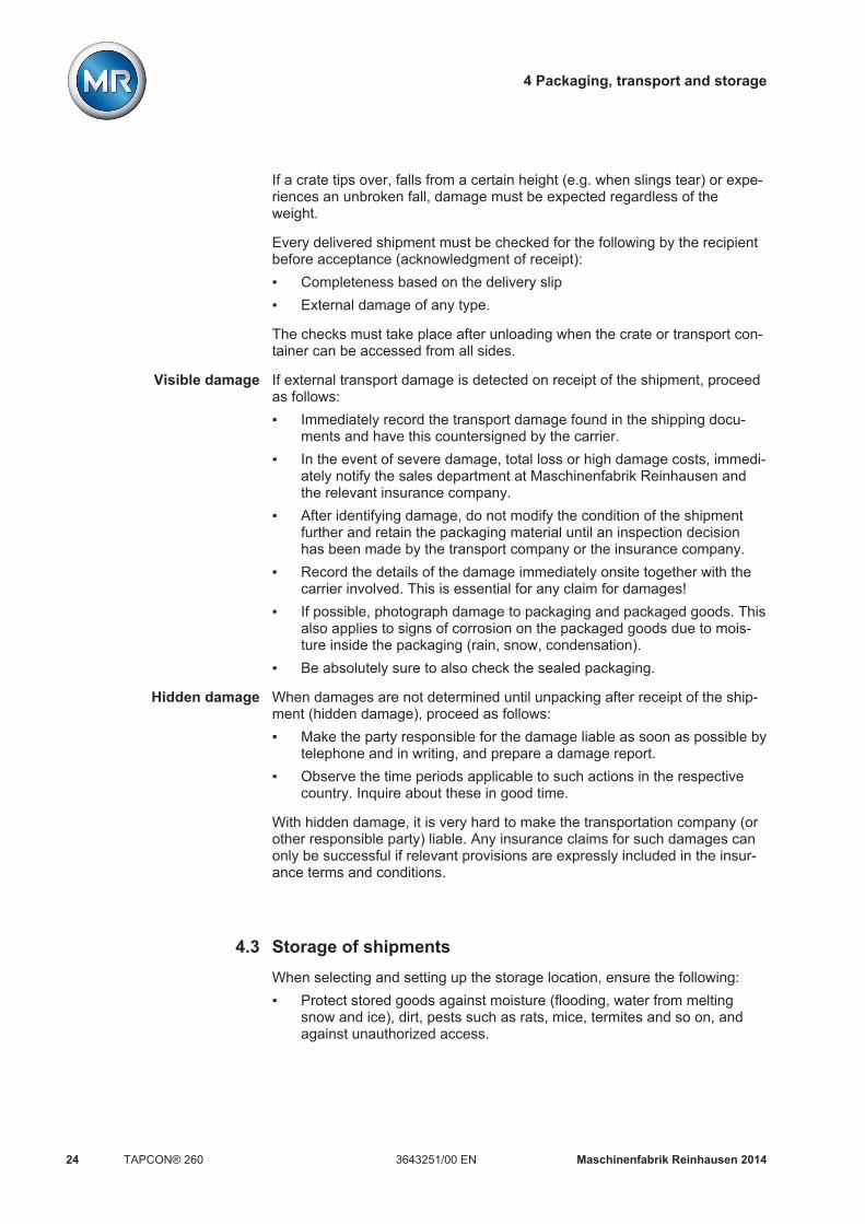
If a crate tips over, falls from a certain height (e.g. when slings tear) or expe-riences an unbroken fall, damage must be expected regardless of theweight.
Every delivered shipment must be checked for the following by the recipientbefore acceptance (acknowledgment of receipt): Completeness based on the delivery slip External damage of any type.
The checks must take place after unloading when the crate or transport con-tainer can be accessed from all sides.
If external transport damage is detected on receipt of the shipment, proceedas follows: Immediately record the transport damage found in the shipping docu-
ments and have this countersigned by the carrier. In the event of severe damage, total loss or high damage costs, immedi-
ately notify the sales department at Maschinenfabrik Reinhausen andthe relevant insurance company.
After identifying damage, do not modify the condition of the shipmentfurther and retain the packaging material until an inspection decisionhas been made by the transport company or the insurance company.
Record the details of the damage immediately onsite together with thecarrier involved. This is essential for any claim for damages!
If possible, photograph damage to packaging and packaged goods. Thisalso applies to signs of corrosion on the packaged goods due to mois-ture inside the packaging (rain, snow, condensation).
Be absolutely sure to also check the sealed packaging.
When damages are not determined until unpacking after receipt of the ship-ment (hidden damage), proceed as follows: Make the party responsible for the damage liable as soon as possible by
telephone and in writing, and prepare a damage report. Observe the time periods applicable to such actions in the respective
country. Inquire about these in good time.
With hidden damage, it is very hard to make the transportation company (orother responsible party) liable. Any insurance claims for such damages canonly be successful if relevant provisions are expressly included in the insur-ance terms and conditions.
Storage of shipmentsWhen selecting and setting up the storage location, ensure the following: Protect stored goods against moisture (flooding, water from melting
snow and ice), dirt, pests such as rats, mice, termites and so on, andagainst unauthorized access.
Visible damage
Hidden damage
4.3

4 Packaging, transport and storage
Maschinenfabrik Reinhausen 2014 253643251/00 EN TAPCON® 260
Store the crates on timber beams and planks as a protection against ris-ing damp and for better ventilation.
Ensure sufficient carrying capacity of the ground. Keep entrance paths free. Check stored goods at regular intervals. Also take appropriate action af-
ter storms, heavy rain or snow and so on.

5 Mounting
Maschinenfabrik Reinhausen 201426 3643251/00 ENTAPCON® 260
MountingThis chapter describes how to correctly mount and connect the device. Notethe connection diagrams provided.
WARNING Electric shockRisk of fatal injury due to electrical voltage. De-energize the device and system peripherals and lock them to pre-
vent them from being switched back on. Do so by short-circuiting the current transformer; do not idle the current
transformer.
NOTICE
Electrostatic dischargeDamage to the device due to electrostatic discharge. Take precautionary measures to prevent the build-up of electrostatic
charges on work surfaces and personnel.
PreparationThe following tools are needed for mounting: Screwdriver for the fixing bolts (M6) Small screwdriver for connecting the signal lines and supply lines
Depending on installation site and mounting variant, you may need addition-al tools and corresponding attachment material (screws, nuts, washers)which are not included in the scope of supply.
Mounting deviceDepending on your order, you can mount the device in one of the followingvariants: 19" frame (in accordance with DIN 41494 Part 5) 19" flush control panel frame ½-19" mounting frame for wall mounting
Below you will find a description of how to mount the device in a 19" frame.For control panel installation or wall mounting, note the technical files sup-plied.
To mount the device in a 19" frame, proceed as follows:1. Place cage nuts in the desired locations on the 19" frame, noting the
device dimensions [ 123].
5
5.1
5.2

5 Mounting
Maschinenfabrik Reinhausen 2014 273643251/00 EN TAPCON® 260
2. Place device in 19" frame and screw down.
Figure 7: Example of device mounting in a 19" frame
Connecting deviceThe following section describes how to make the electrical connection to thedevice.
WARNING Electric shockDanger of death due to connection mistakes Ground device using the grounding screw on the housing. Pay attention to the phase difference of the secondary terminals for the
current transformer and voltage transformer. Connect the output relays correctly to the motor-drive unit.
Cable recommendation
Please note the following recommendation from Maschinenfabrik Reinhau-sen when wiring the device.
Excessive electrical power can prevent the relay contacts from breaking thecontact current. In control circuits operated with alternating current, take intoaccount the effect of the line capacitance of long control lines on the func-tion of the relay contacts.
Cable Card Terminal Cable type Conductorcross-sec-tion
Max. length
Power supply SU X1:1/2 Unshielded 1.5 mm² -Voltagemeasurement
MI/MI1 1/2 Shielded 1.5 mm² -
5.3
5.3.1

5 Mounting
Maschinenfabrik Reinhausen 201428 3643251/00 ENTAPCON® 260
Cable Card Terminal Cable type Conductorcross-sec-tion
Max. length
Currentmeasurement
MI/MI1 5/6/9/10 Unshielded 4 mm² -
Relay* IO X1:1...10X1:19...26
Unshielded 1.5 mm² -
Relay* UC X1:1...10 Unshielded 1.5 mm² -Signal inputs IO X1:11...17
X1:27...34Shielded 1.0 mm² -
Signal inputs UC X1:11...17X1:27...34
Shielded 1.0 mm² -
CAN bus CPU 1...5 Shielded 1.0 mm² 2000 mTable 7: Recommendation for connection cable (standard connections)
*) Observe line capacitance, see note above.
Cable Card Terminal Cable type Conductorcross-sec-tion
Max. length
AC AC X1/2:1/2 Unshielded 1.5 mm² -Analog inputs AD8 X1:1...3 Shielded 1.5 mm² 400 m (< 25 Ω/km)Analog out-puts
AN/AN1 X1 Shielded 1mm² -
RS-232 CIC X8 Shielded 0.25 mm² 25 mRS-485 CIC X9 Shielded 0.75 mm² 1000 m (< 50 Ω/km)Ethernet SID
CICRJ45X7
shielded, CAT7
- 100 m
Media con-verter
MC1 - Optical fiberwith MTRJ-ST duplexpatch cable
- -
Media con-verter
MC2 - Fiber-opticcable, con-nector type:F-ST; fibertype: multimode/singlemode; wave-length:1310 nm
- -
Table 8: Recommendation for connection cable (optional connections)

5 Mounting
Maschinenfabrik Reinhausen 2014 293643251/00 EN TAPCON® 260
Information about laying fiber-optic cable
To ensure the smooth transfer of data via the fiber-optic cable, you must en-sure that mechanical loads are avoided when laying the fiber-optic cable andlater on during operation.
Please note the following: Radii must not fall below the minimum permissible bend radii (do not
bend fiber-optic cable). The fiber-optic cables must not be over-stretched or crushed. Observe
the permissible load values. The fiber-optic cables must not be twisted. Be aware of sharp edges which could damage the fiber-optic cable's
coating when laying or could place mechanical loading on the coatinglater on.
Provide a sufficient cable reserve near distributor cabinets for example.Lay the reserve such that the fiber-optic cable is neither bent nor twistedwhen tightened.
Electromagnetic compatibility
The device has been developed in accordance with applicable EMC stan-dards. The following points must be noted in order to maintain the EMCstandards.
Wiring requirement of installation site
Note the following when selecting the installation site: The system's overvoltage protection must be effective. The system's ground connection must comply with all technical regula-
tions. Separate system parts must be joined by a potential equalization. The device and its wiring must be at least 10 m away from circuit-break-
ers, load disconnectors and busbars.
Wiring requirement of operating site
Note the following when wiring the operating site: The connection cables must be laid in metallic cable ducts with a ground
connection. Do not route lines which cause interference (for example power lines)
and lines susceptible to interference (for example signal lines) in thesame cable duct.
Maintain a gap of at least 100 mm between lines causing interferenceand those susceptible to interference.
5.3.2
5.3.3
5.3.3.1
5.3.3.2

5 Mounting
Maschinenfabrik Reinhausen 201430 3643251/00 ENTAPCON® 260
Figure 8: Recommended wiring
1 Cable duct for lines causinginterference
3 Cable duct for lines suscepti-ble to interference
2 Interference-causing line (e.g.power line)
4 Line susceptible to interfer-ence (e.g. signal line)
Short-circuit and ground reserve lines. The device must never be connected using multi-pin collective cables. Signal lines must be routed in a shielded cable. The individual conductors (outgoing conductors/return conductors) in
the cable core must be twisted in pairs. The shield must be fully (360º) connected to the device or a nearby
ground rail.
Using "pigtails" may limit the effectiveness of the shielding. Connect close-fitting shield to cover all areas.

5 Mounting
Maschinenfabrik Reinhausen 2014 313643251/00 EN TAPCON® 260
Figure 9: Recommended connection of the shielding
1 Connection of the shieldingusing a "pigtail"
2 Shielding connection coveringall areas
Wiring requirement in control cabinet
Note the following when wiring the control cabinet: The control cabinet for fitting the device must be prepared in accord-
ance with EMC requirements:– Functional division of control cabinet (physical separation)– Constant potential equalization (all metal parts are joined)– Line routing in accordance with EMC requirements (separation of
lines which cause interference and those susceptible to interfer-ence)
– Optimum shielding (metal housing)– Overvoltage protection (lightning protection)– Collective grounding (main grounding rail)– Cable bushings in accordance with EMC requirements– Any contactor coils present must be interconnected
The device's connection cables must be laid in close contact with thegrounded metal housing or in metallic cable ducts with a ground con-nection.
Signal lines and power lines/switching lines must be laid in separate ca-ble ducts.
The device must be grounded at the screw provided using a groundstrap (cross-section min. 8 mm²). The device's ground connection is afunctional ground and serves to dissipate interfering currents.
5.3.3.3

5 Mounting
Maschinenfabrik Reinhausen 201432 3643251/00 ENTAPCON® 260
Figure 10: Ground strap connection
Ground connection for wiring inside the device
The diagram below shows the ground connection for wiring inside the de-vice.
Information about shielding the CAN bus
In order for the CAN bus to operate faultlessly, you have to connect theshielding using one of the following variants. If neither connection variant ispossible, we would recommend using fiber optic cables. Fiber optic cablesdecouple the voltage regulators and are not sensitive to electromagnetic in-terferences (surge and burst).
NOTICE
Damage to the deviceIf the CAN bus cable's shielding is connected to devices with different po-tential, current may flow over the shielding. This current may damage thecommunication cards. Connect the devices to a potential compensation rail to compensate for
potential Ensure that the CAN bus cable's shielding is only connected to one de-
vice if both devices have different potentials.
5.3.3.4

5 Mounting
Maschinenfabrik Reinhausen 2014 333643251/00 EN TAPCON® 260
Variant 1: The connected devices share the same potential
If the devices to be connected share the same potential, proceed as follows:1. Connect all devices to a potential compensation rail to compensate for
the potential.2. Connect CAN bus cable's shielding to all connected devices.
Variant 2: The connected devices have different potential
Note that the shielding is less effective with this variant.
If the devices to be connected have different potential, proceed as follows: Connect CAN bus cable's shielding to just one device.
Connecting shielding
Connect the CAN bus cable's shielding to the intended point on the CPUcard using the cable clips provided:
Figure 11: Securing the shielding
1 Securing the CAN bus cable's shielding
Connecting cables to the system periphery
To obtain a better overview when connecting cables, only use as manyleads as necessary.
To connect cables to the system periphery, proceed as follows:ü Use only the specified cables for wiring. Note the cable recommendation
[ 27]. Connect the lines to be wired to the device to the system periphery as
shown in the connection diagrams supplied.
5.3.4

5 Mounting
Maschinenfabrik Reinhausen 201434 3643251/00 ENTAPCON® 260
Wiring device
To obtain a better overview when connecting cables, only use as manyleads as necessary.
To wire the device, proceed as follows:ü Use only the specified cables for wiring. Note the cable recommendation
[ 27].ü Wire the lines to the system periphery [ 33]. Wire the device according to the connection diagram.
Checking functional reliability
To ensure that the device is wired correctly, check its functional reliability.
NOTICE
Damage to device and system peripheryAn incorrectly connected device can lead to damages in the device and sys-tem periphery. Check the entire configuration before commissioning. Prior to commissioning, be sure to check the actual voltage and operat-
ing voltage.
Check the following: Once you have connected the device to the grid, the screen displays the
MR logo and then the operating screen. The green Operating display LED top left on the device's front panel
lights up.
The device is fully mounted and can be configured. The actions required forthis are described in the following chapter.
5.3.5
5.3.6

6 Commissioning
Maschinenfabrik Reinhausen 2014 353643251/00 EN TAPCON® 260
CommissioningYou need to set several parameters and perform function tests before com-missioning the device. These are described in the following sections.
NOTICE
Damage to device and system peripheryAn incorrectly connected device can lead to damages in the device and sys-tem periphery. Check the entire configuration before commissioning. Prior to commissioning, be sure to check the actual voltage and operat-
ing voltage.
We recommend using a device for industrial instrumentation to record theactual transformer voltage value in order to evaluate how the device is func-tioning.
Setting the display contrastYou can adjust the contrast in the display with the help of an adjustmentscrew on the front of the device. To adjust the contrast, proceed as follows: Use a screwdriver to turn the adjustment screw on the front until the
contrast is adjusted to the desired setting.
Figure 12: Setting the display contrast
Setting parametersTo commission the device, you must set the following parameters. For moredetailed information about the parameters, refer to the respective sections.
6
6.1
6.2

6 Commissioning
Maschinenfabrik Reinhausen 201436 3643251/00 ENTAPCON® 260
Setting the language
You can use this parameter to set the display language for the device. Thefollowing languages are available:
English ItalianGerman PortugueseFrench RussianSpanish
To set the language, proceed as follows:
1. > Configuration > General.ð Language
2. Press or to select the required language.
3. Press .ð The language is set.
Setting date and time
You must set the system date and system time on the device. You must setthe date and time in the following formats:
Date TimeDD.MM.YY HH:MM:SS
Table 9: Formats
The time does not switch from daylight saving time to standard time andback automatically. You have to change the time manually.
Time
To set the time, proceed as follows:
1. > Configuration > Continue > Memory > Press until the desired display appears.ð Time
2. Press to highlight a digit.ð The desired position is highlighted and the value can be changed.
3. Press to increase the value or to reduce it.
4. Press .ð The time is set.
6.2.1
6.2.2

6 Commissioning
Maschinenfabrik Reinhausen 2014 373643251/00 EN TAPCON® 260
Date
To set the date, proceed as follows:
1. > Configuration > Continue > Memory > Press until the desired display appears.ð Date
2. Press to highlight a digit.ð The desired position is highlighted and the value can be changed.
3. Press to increase the value or to reduce it.
4. Press .ð The date is set.
Setting further parameters
Set further parameters to commission the device. More detailed informationabout each of the parameters can be found in the Functions and settings[ 39] chapter.
Setting transformer data
Set the transformer data and phase difference of the current transformer andvoltage transformer. Note that you need to set the parameters for both thelow-voltage side and high-voltage side of the transformer:1. Set primary transformer voltage [ 72].2. Set secondary transformer voltage [ 72].3. Set primary transformer current [ 73].4. Select current transformer connection [ 73].5. Select transformer circuit [ 74].
Setting NORMset
If you want to commission voltage regulation quickly, you can activateNORMset mode. If you want to set the parameters yourself, continue withthe sections below. Activate NORMset and set the relevant parameters [ 46].
Setting control parameters
Set the following control parameters. Note that you need to set the parame-ters for both the low-voltage side and high-voltage side of the transformer:1. Set desired value 1 [ 50].2. Set the bandwidth [ 51].3. Set delay time T1 [ 53].
6.2.3

6 Commissioning
Maschinenfabrik Reinhausen 201438 3643251/00 ENTAPCON® 260
Setting control response if negative power flow
Set the following parameters to activate voltage regulation if the power flowis negative:1. Activate high-voltage side regulation [ 55].2. Set minimum current [ 56].3. Set change delay [ 56].4. Set switching direction if negative power flow [ 57].5. Set line drop compensation if negative power flow [ 57].
Setting line drop compensation (optional)
If you need line drop compensation, you must set all important parametersfor this:1. Select the LDC compensation method [ 67].2. Set the line data for the ohmic voltage drop Ur [ 68].3. Set the line data for the inductive voltage drop Ux [ 69].
Setting parallel operation
If you need parallel operation, you must set all important parameters for this:1. Set parallel operation method [ 78].2. Assign the CAN bus address [ 78].
Setting control system protocol
Set the following parameters:1. Set network address [ 85].2. Set network mask [ 86].3. Set time server address [ 86].4. Set gateway [ 87].5. Enter IED name [ 87].

7 Functions and settings
Maschinenfabrik Reinhausen 2014 393643251/00 EN TAPCON® 260
Functions and settingsThis chapter describes all the functions and setting options for the device.
Key lockThe device is equipped with a key lock to prevent unintentional operation.You can only set or change the parameters when the key lock is deactivatedin manual mode.
Activating key lock
To activate the key lock, proceed as follows:
Press and at the same time.ð A confirmation appears in the display for a brief period. The key lock is
activated. Parameters can no longer be entered.
Deactivating key lock
To deactivate the key lock, proceed as follows:
Press and at the same time.ð The key lock is deactivated. Parameters can be entered.
Carrying out tap-change operation manuallyIn manual mode [ 16] you can manually carry out an on-load tap-changertap-change operation. To do this, you can choose whether you want toswitch 1 motor-drive unit individually (ED 1...ED 3) or all 3 motor-drive unitsat the same time (ED all).
By switching the motor-drive units individually, you can compare the tap po-sitions of the on-load tap-changers in the 3 transformers. If the tap positionsare different, the tap difference LED lights up.
To carry out a tap-change operation manually, proceed as follows:
1. If necessary, press to activate manual mode.
2. Press and hold down or .ð The "Syn. Control up/down" display appears.
3. Press ... as required to select the option you want.ð The tap-change operation is carried out.
7
7.1
7.2

7 Functions and settings
Maschinenfabrik Reinhausen 201440 3643251/00 ENTAPCON® 260
GeneralYou can undertake general settings on the device in the General menu item.You can set the following general parameters: Language Regulator ID Baud rate (COM1 setting) Voltage display kV/V Current display %/A Raise/Lower pulse duration Configuration of free inputs/outputs (IOs) Display dimming Motor runtime Tapping direction
Setting device ID
You can use the device ID parameter to assign a 4-digit ID to the device.This ID is used to uniquely identify the device in the TAPCON®-trol software.
To set the device ID, proceed as follows:
1. > Configuration > General > Press until the desiredparameter is displayed.ð Regulator ID.
2. Press to change the first digit.ð If you wish to enter a multi-digit sequence, proceed to step 3. If you
do not wish to enter additional digits, proceed to step 7.
3. Press (digit > 9) until another digit position appears.
4. If necessary, press in order to highlight the digit position.ð The required digit is highlighted and can be changed.
5. Press or to change the digit.6. Repeat steps 3 to 5 until all required digits have been entered.
7. Press .ð The device ID is set.
Setting the baud rate
You can use this parameter to set the COM1 interface's baud rate. You canselect the following options: 9.6 kilobaud 19.2 kilobaud
7.3
7.3.1
7.3.2
7 Functions and settings
Maschinenfabrik Reinhausen 2014 413643251/00 EN TAPCON® 260
38.4 kilobaud 57.6 kilobaud
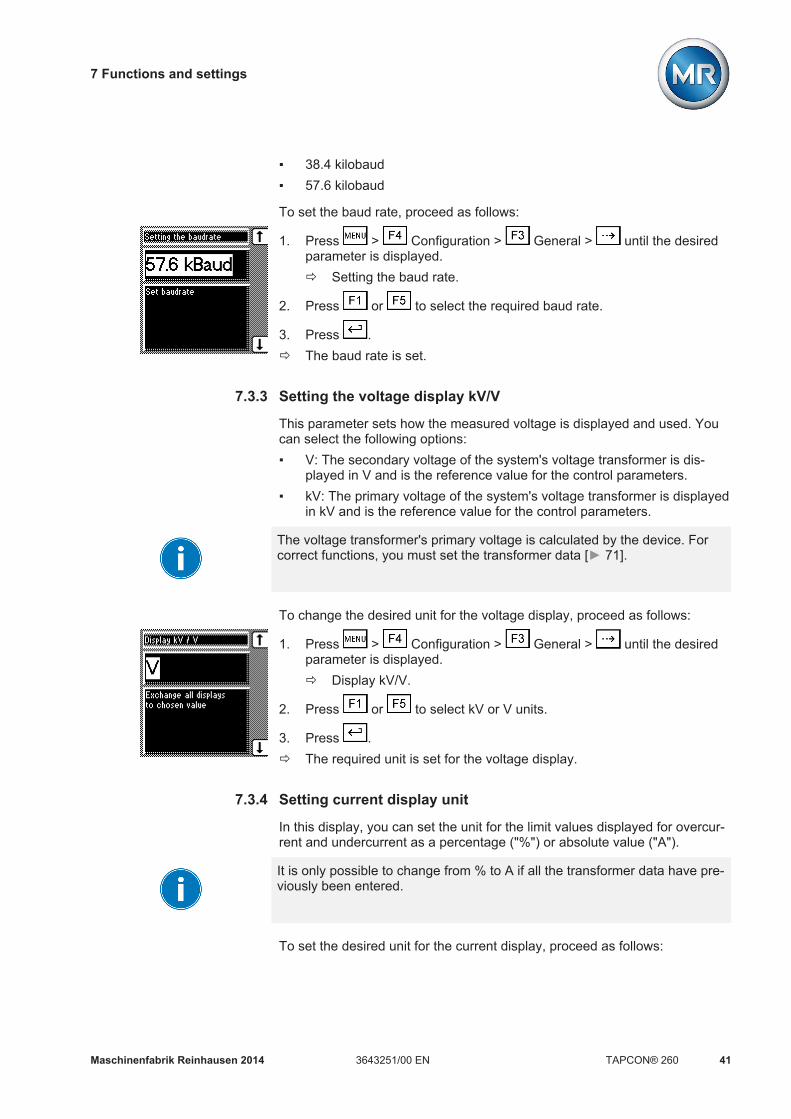
To set the baud rate, proceed as follows:
1. Press > Configuration > General > until the desiredparameter is displayed.ð Setting the baud rate.
2. Press or to select the required baud rate.
3. Press .ð The baud rate is set.
Setting the voltage display kV/V
This parameter sets how the measured voltage is displayed and used. Youcan select the following options: V: The secondary voltage of the system's voltage transformer is dis-
played in V and is the reference value for the control parameters. kV: The primary voltage of the system's voltage transformer is displayed
in kV and is the reference value for the control parameters.
The voltage transformer's primary voltage is calculated by the device. Forcorrect functions, you must set the transformer data [ 71].
To change the desired unit for the voltage display, proceed as follows:
1. Press > Configuration > General > until the desiredparameter is displayed.ð Display kV/V.
2. Press or to select kV or V units.
3. Press .ð The required unit is set for the voltage display.
Setting current display unit
In this display, you can set the unit for the limit values displayed for overcur-rent and undercurrent as a percentage ("%") or absolute value ("A").
It is only possible to change from % to A if all the transformer data have pre-viously been entered.
To set the desired unit for the current display, proceed as follows:
7.3.3
7.3.4

7 Functions and settings
Maschinenfabrik Reinhausen 201442 3643251/00 ENTAPCON® 260
1. Press > Configuration > General > until the desiredparameter is displayed.ð Display %/A
2. Press or to select % or A units.
3. Press .ð The required unit is set for the current display.
Setting the switching pulse time
You can use this parameter to set the duration of the switching pulse for themotor-drive unit.
If you set the switching pulse time to 0 s, the motor-drive unit is activatedwith a continuous signal. The signal then remains active for as long as the
or keys are pressed.
If you set the switching pulse time to 1.5 seconds for example, after the setdelay time T1 or delay time T2 there will be a switching pulse of 1.5 sec-onds .
The waiting time between 2 consecutive switching pulses corresponds to theset delay time T1 or delay time T2 .
Figure 19: Switching pulse time in normal mode
1 Set delay time T1 or T2 2 Set switching pulse time (forexample 1.5 seconds)
7.3.5
Switching pulse in normalmode

7 Functions and settings
Maschinenfabrik Reinhausen 2014 433643251/00 EN TAPCON® 260
If the motor-drive unit does not start with the factory setting (1.5 seconds),you need to extend the raise switching pulse time / lower switching pulsetime.
If you set the raise switching pulse time or lower switching pulse time to1.5 seconds, for example , the next earliest switching pulse occurs in rapidreturn control mode 1.5 seconds after the previous switching pulseended.
Figure 20: Switching pulse in rapid return control mode
1 Start of first raise switchingpulse/lower switching pulse
3 Earliest time for the next raiseswitching pulse/lower switch-ing pulse (for example1.5 seconds)
2 Set switching pulse time (forexample 1.5 seconds)
To set the pulse duration, proceed as follows:
1. > Configuration > General > Press until the desiredparameter is displayed.ð R/L pulse duration.
2. Press or to select the pulse duration you want.
3. Press .ð The R/L pulse duration is now set.
Switching pulse for rapidreturn control

7 Functions and settings
Maschinenfabrik Reinhausen 201444 3643251/00 ENTAPCON® 260
Dimming display
You can use this parameter to activate or deactivate automatic display dim-ming. You can select the following options: On: The display is automatically dimmed if no key is pressed for 15 mi-
nutes. The display returns to full brightness by pressing any key. Off: Automatic display dimming is deactivated.
Activating this function extends the display's service life.
To activate/deactivate automatic display dimming, proceed as follows:
1. Press > Configuration > General > until the desiredparameter is displayed.ð Display off.
2. Press or to activate/deactivate automatic dimming.
3. Press .ð Automatic dimming is set.
Setting motor runtime monitoring
You can use this motor runtime parameter to set the motor runtime. The mo-tor-drive unit's runtime can also be monitored by the device. This function isused to identify motor-drive unit malfunctions during the tap-change opera-tion and to trigger any actions needed.
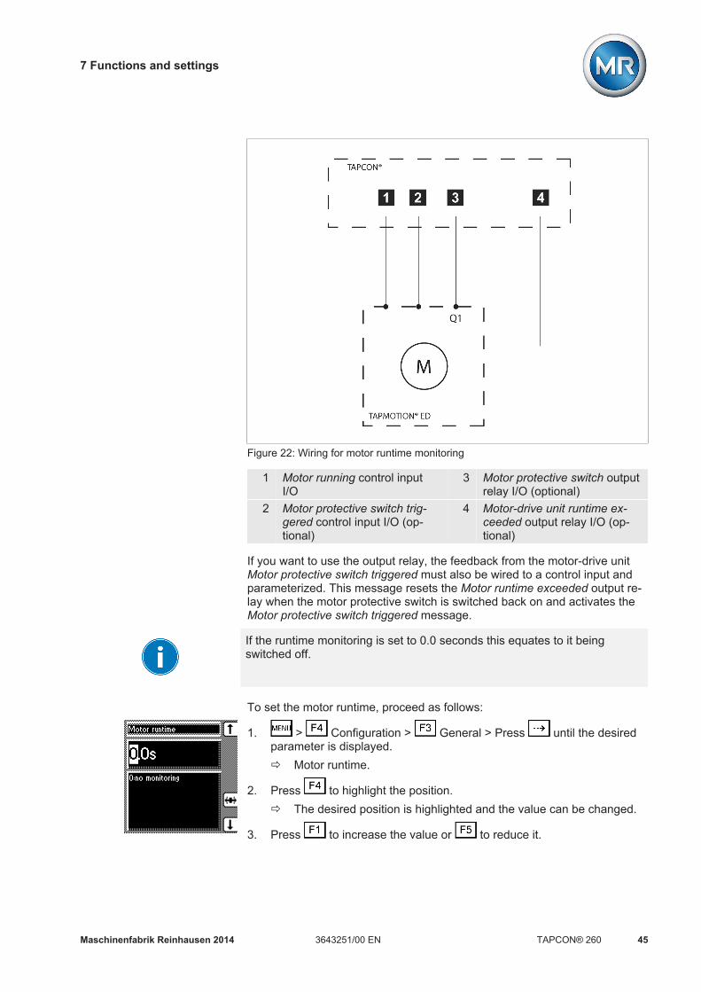
The motor-drive unit issues the Motor-drive unit running signal during thetap-change operation. This signal is present until the tap-change operation iscomplete. The device compares the duration of this signal with the set motorruntime. If the set motor runtime is exceeded, the device triggers the follow-ing actions:1. Motor runtime monitoring message is issued2. Continuous signal via output relay Motor-drive unit runtime exceeded
(optional)3. Pulse signal via Trigger motor protective switch output relay (optional)
To use runtime monitoring, you need to correctly wire the correspondingcontrol input and parameterize to Motor running. The motor runtime must al-so be set.
If you want to monitor the motor runtime, the device and motor-drive unitmust be connected and parameterized as shown below.
7.3.6
7.3.7
Behavior
Parameterizing controlinput
Wiring control input/outputrelay
7 Functions and settings
Maschinenfabrik Reinhausen 2014 453643251/00 EN TAPCON® 260
Figure 22: Wiring for motor runtime monitoring
1 Motor running control inputI/O
3 Motor protective switch outputrelay I/O (optional)
2 Motor protective switch trig-gered control input I/O (op-tional)
4 Motor-drive unit runtime ex-ceeded output relay I/O (op-tional)
If you want to use the output relay, the feedback from the motor-drive unitMotor protective switch triggered must also be wired to a control input andparameterized. This message resets the Motor runtime exceeded output re-lay when the motor protective switch is switched back on and activates theMotor protective switch triggered message.
If the runtime monitoring is set to 0.0 seconds this equates to it beingswitched off.
To set the motor runtime, proceed as follows:
1. > Configuration > General > Press until the desiredparameter is displayed.ð Motor runtime.
2. Press to highlight the position.ð The desired position is highlighted and the value can be changed.
3. Press to increase the value or to reduce it.

7 Functions and settings
Maschinenfabrik Reinhausen 201446 3643251/00 ENTAPCON® 260
4. Press .ð The motor runtime is set.
NORMsetNORMset mode is used for quickly starting voltage regulation. In NORMsetmode, the bandwidth and delay time parameters are automatically adaptedto the requirements of the grid.
To start NORMset mode, you must set the following parameters: Normset activation Desired value 1 Primary voltage Secondary voltage
Line drop compensation cannot be performed in NORMset mode.
Set the following parameters to operate the device in NORMset mode.
Activating/deactivating NORMset
You can use this parameter to activate NORMset mode.
A manual tap-change operation is required to activate NORMset. This ishow the voltage regulator determines the bandwidth required.If the transformer is switched off, another manual tap-change operation isrequired.
Proceed as follows to activate/deactivate NORMset mode:
1. > NORMsetð NORMset activation.
2. Press or to activate NORMset by selecting On or to deactivateNORMset by selecting Off.
3. Press .ð NORMset is activated/deactivated.
Setting the primary voltage
With this parameter, you can set the voltage transformer's primary voltage.
7.4

7 Functions and settings
Maschinenfabrik Reinhausen 2014 473643251/00 EN TAPCON® 260
You have to set this parameter for both the low-voltage side (primary volt-age) and the high-voltage side (primary voltage2). Proceed as follows to setthe primary voltage:
1. > NORMset > Press until the desired parameter is dis-played.ð Primary voltage/Primary voltage2.
2. Press to increase the value or to reduce it.
3. Press .ð The primary voltage is set.
Setting the secondary voltage
With this parameter, you can set the voltage transformer's secondary volt-age.
You have to set this parameter for both the low-voltage side (secondary volt-age) and the high-voltage side (secondary voltage2). Proceed as follows toset the secondary voltage:
1. > NORMset > Press until the desired parameter is dis-played.ð Secondary voltage/Secondary voltage2.
2. Press to increase the value or to reduce it.
3. Press .ð The secondary voltage is set.
Setting desired value 1
With this parameter, you can set the desired value for automatic voltage reg-ulation. You can enter the desired value in V or in kV. If you enter the de-sired value in V, the value relates to the voltage transformer's secondaryvoltage. If you set the desired value in kV, the value relates to the voltagetransformer's primary voltage.
Settings in kV are only possible if you have previously entered the parame-ters for primary and secondary voltage.
You have to set this parameter for both the low-voltage side (desired value1) and the high-voltage side (winding2 desired value1). Proceed as followsto set the desired value:
1. > NORMset > Press until the desired parameter is dis-played.ð Desired value 1/Winding2 desired value 1.

7 Functions and settings
Maschinenfabrik Reinhausen 201448 3643251/00 ENTAPCON® 260
2. Press to increase the value or to reduce it.
3. Press .ð The desired value is set.
Control parametersAll of the parameters required for the regulation function are described in thissection.
Note that the voltage of either the high-voltage side or the low-voltage sideof the transformer is regulated by the device. You can set the conditions un-der which the high-voltage side or low-voltage side is regulated in the Re-verse [ 55] menu.
For voltage regulation, you can set the following parameters: Desired values 1…3 / Winding 2 desired values 1...3 Bandwidth Delay time Control response T1 Delay time T2
For voltage regulation, you can set delay time T1 and also delay time T2.The following sections describe how the regulation function responds in bothcases:
Response only to delay time T1
If the measured voltage Vactual is within the set bandwidth , no controlcommands are issued to the motor-drive unit for the tap-change operation.Control commands will also not be issued to the motor-drive unit if within theset delay time T1 the measured voltage returns to the tolerance band-width . However, if the measured voltage deviates from the set bandwidthfor a long period , a tap-change command occurs after the set delaytime T1. The on-load tap-changer carries out a tap-change in a positive ornegative direction to return to the tolerance bandwidth.
7.5

7 Functions and settings
Maschinenfabrik Reinhausen 2014 493643251/00 EN TAPCON® 260
Figure 26: Response of the regulation function with delay time T1
1 + B %: Upper limit 4 Set delay time T12 Vdesired: Desired value 5 Vactual: Measured voltage3 - B %: Lower limit 6 B%: Tolerance bandwidthA Vactual is outside the band-
width. Delay time T1 starts.B Vactual is within the bandwidth
before delay time T1 is com-plete.
C Vactual is outside the band-width. Delay time T1 starts.
D Vactual is still outside the band-width when delay time T1 iscomplete. Tap-change opera-tion is initiated.
Response with delay times T1 and T2
Delay time T2 can be used to correct major control deviations more quickly.Ensure that you set a lower value for delay time T2 than delay time T1.
If the measured voltage Vactual deviates from the set bandwidth for a longperiod , a control impulse is output to the motor-drive unit after the set de-lay time T1 . If the measured voltage Vactual is still outside the bandwidth,delay time T2 starts once delay time T1 is complete. Once delay time T2is complete, a control impulse is again output to the motor-drive unit for thetap change to return to the tolerance bandwidth.

7 Functions and settings
Maschinenfabrik Reinhausen 201450 3643251/00 ENTAPCON® 260
Figure 27: Response of the regulation function with delay times T1 and T2
1 + B %: Upper limit 4 Set delay times T1 and T2.2 Vdesired: Desired value 5 Vactual: Measured voltage3 - B %: Lower limit 6 B%: Tolerance bandwidthA Vactual is outside the band-
width. Delay time T1 starts.B Delay time T1 complete. Tap
change triggered.C Delay time T2 complete. Tap
change triggered.
The following sections describe how to set the relevant control parameters.
Setting desired value 1...3
You can use this parameter to set up to 3 desired voltage values Udesired. Thedesired voltage value is specified as a fixed value. The desired value 1 is thedefault desired value. Desired values 2 and 3 are used to set the desiredvoltage level remotely (optional).
Desired values set in kV refer to the primary voltage of the voltage trans-former. Desired values set in V refer to the secondary voltage of the voltagetransformer. The transformer data must be entered correctly for this display.
7.5.1
Reference of kV and V forvoltage transformer

7 Functions and settings
Maschinenfabrik Reinhausen 2014 513643251/00 EN TAPCON® 260
You have to set this parameter for both the low-voltage side (desired values1...3) and the high-voltage side (winding 2 desired values 1...3). Proceed asfollows to set the desired value:
1. > Parameter > Control parameter > Press until thedesired parameter is displayed.
2. If you have already entered the transformer data, press to selectthe unit you want: "V" or "kV".
3. Press to highlight the position.ð The desired position is highlighted and the value can be changed.
4. Press to increase the value or to reduce it.
5. Press .ð The desired value is set.
Bandwidth
You can use this parameter to set the maximum permissible deviation inmeasured voltage UAct. The deviation relates to the activated desired value.The following sections describe how you determine and set the bandwidthrequired.
Determining bandwidth
In order to set the correct value, the transformer's step voltage and nominalvoltage must be known.
You have to set the bandwidth in such a way that the output voltage of thetransformer (VAct) returns to within the specified tolerance bandwidth after thetap change. If too small a bandwidth is defined, the output voltage exceedsthe bandwidth selected and the device immediately issues a tap-changecommand in the opposite direction. If a very large bandwidth is selected, thisresults in a major control deviation.
The following value is recommended for the bandwidth setting:
Figure 29: Recommended bandwidth
Un-1 Step voltage of tap position n-1Un Step voltage of tap position nUnom Nominal voltage
7.5.2
7.5.2.1
Too small/large abandwidth
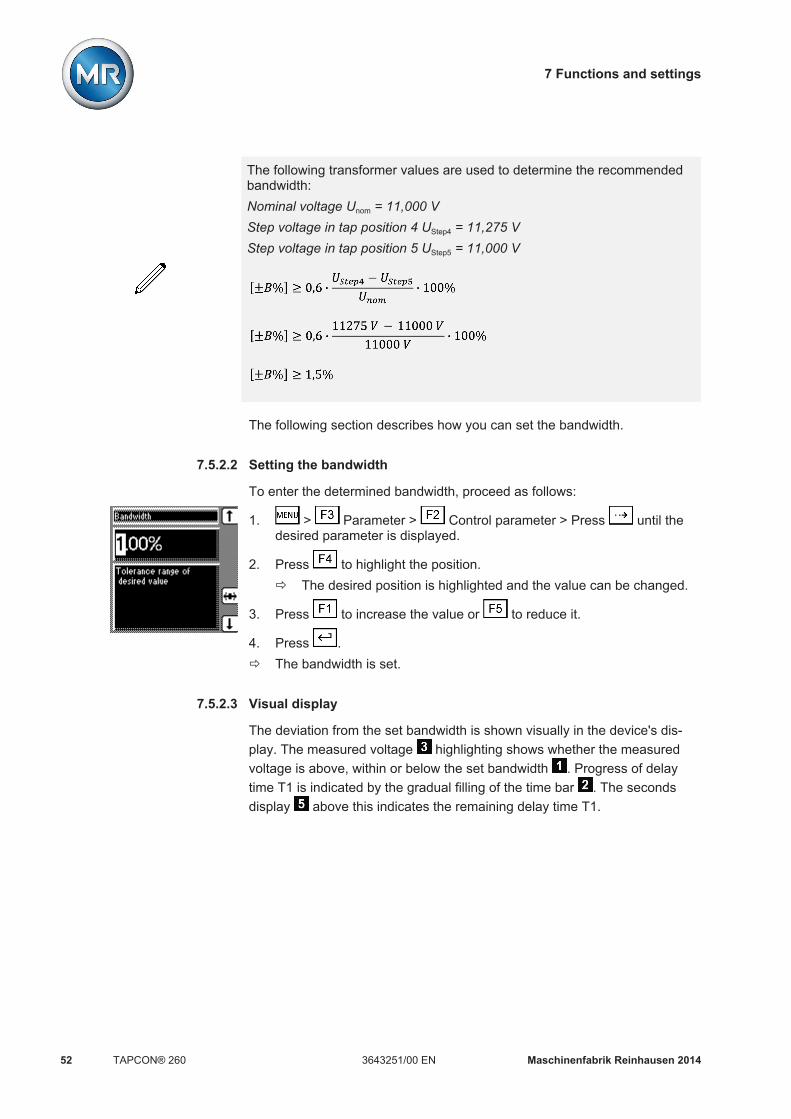
7 Functions and settings
Maschinenfabrik Reinhausen 201452 3643251/00 ENTAPCON® 260
The following transformer values are used to determine the recommendedbandwidth:Nominal voltage Unom = 11,000 VStep voltage in tap position 4 UStep4 = 11,275 VStep voltage in tap position 5 UStep5 = 11,000 V
The following section describes how you can set the bandwidth.
Setting the bandwidth
To enter the determined bandwidth, proceed as follows:
1. > Parameter > Control parameter > Press until thedesired parameter is displayed.
2. Press to highlight the position.ð The desired position is highlighted and the value can be changed.
3. Press to increase the value or to reduce it.
4. Press .ð The bandwidth is set.
Visual display
The deviation from the set bandwidth is shown visually in the device's dis-play. The measured voltage highlighting shows whether the measuredvoltage is above, within or below the set bandwidth . Progress of delaytime T1 is indicated by the gradual filling of the time bar . The secondsdisplay above this indicates the remaining delay time T1.
7.5.2.2
7.5.2.3

7 Functions and settings
Maschinenfabrik Reinhausen 2014 533643251/00 EN TAPCON® 260
Figure 30: Visual display of deviation from desired value
1 Bandwidth (upper and lowerlimit)
4 Desired voltage value URef
2 Time bar for delay time T1 5 Remaining delay time T13 Measured voltage UAct
Setting delay time T1
Use this parameter to set delay time T1. This function delays the issuing of atap-change command for a defined period. This prevents unnecessary tap-change operations if the tolerance bandwidth is exited.
To set the delay time T1, proceed as follows:
1. > Parameter > Control parameter > Press until thedesired parameter is displayed.
2. Press to highlight the position.ð The desired position is highlighted and the value can be changed.
3. Press to increase the time or to reduce it.
4. Press .ð The delay time T1 is set.
Setting control response T1
The control response T1 can be set to linear or integral.
With linear control response, the device responds with a constant delay timeregardless of the control deviation.
With integral control response, the device responds with a variable delaytime depending on the control deviation. The greater the control deviation(ΔV) in relation to the set bandwidth (B), the shorter the delay time. The de-lay time can therefore be reduced down to 1 second. This means that thedevice responds faster to large voltage changes in the grid. Regulation accu-racy improves as a result but the frequency of tap-changes increases too.
7.5.3
7.5.4
Linear control response T1
Integral control responseT1

7 Functions and settings
Maschinenfabrik Reinhausen 201454 3643251/00 ENTAPCON® 260
Figure 31: Diagram showing integral control response
ΔV/B Control deviation "ΔV" as % of desired value as ratio to the setbandwidth "B" as % of desired value
1 "Delay time T1" parameter
To set the control response T1, proceed as follows:
1. > Parameter > Control parameter > Press until thedesired parameter is displayed.
2. Press or to set the response you want.
3. Press .ð The control response T1 is set.
Setting delay time T2
With this parameter, you can set delay time T2. Delay time T2 is used tocompensate for large control deviations faster.
The delay time T2 only takes effect if more than one tap-change operation isrequired to return the voltage to within the set bandwidth. The first outputpulse occurs after the set delay time T1. After the set tap-change delay timeT2 has elapsed, additional pulses occur in order to correct the existing con-trol deviation.
The following requirements must be noted to set delay time T2: The delay time T2 must be greater than the switching pulse time. The delay time T2 must be greater than the maximum operating time of
the motor-drive unit. The delay time T2 must be less than the value set for delay time T1.
To set the delay time T2, proceed as follows:
7.5.5

7 Functions and settings
Maschinenfabrik Reinhausen 2014 553643251/00 EN TAPCON® 260
1. > Parameter > Control parameter > Press until the de-sired parameter is displayed.ð Delay time T2.
2. Press to increase the time or to reduce it.
3. Press .ð The delay time T2 is set.
Activating/deactivating delay time T2
To activate/deactivate delay time T2 , proceed as follows:
1. > Parameter > Control parameter > Press until thedesired parameter is displayed.ð T2 activation.
2. Press or to activate/deactivate T2.
3. Press .ð The delay time T2 is activated/deactivated.
Regulation behavior if negative power flowYou can use the parameters in the Reverse menu to set whether the deviceis to regulate the transformer's high-voltage side if power flow is negative.
You can set the following behavior:
Power flow Apparent current Regulation optionsActive current > 0 Apparent current >
minimum current Low-voltage side
Active current < 0 Apparent current >minimum current
High-voltage side Blocking
Active current < 0 oractive current > 0
Apparent current <minimum current
No change to tapwinding
Low-voltage side Blocking
Table 10: Regulation behavior
Activating regulation on high-voltage side
You can use this parameter to activate regulation on the high-voltage side ifthe power flow is negative. If you activate this function, then during negativepower flow (active power < 0) the device uses the measured values and de-sired values of the high-voltage side for automatic voltage regulation.
7.6
7.6.1

7 Functions and settings
Maschinenfabrik Reinhausen 201456 3643251/00 ENTAPCON® 260
To activate high-voltage side regulation, proceed as follows:
1. > Configuration > Continue > Continue > Re-verse.ð HV control if reverse P.
2. Press or to set the option you want.
3. Press .ð The high-voltage side regulation is activated/deactivated.
Setting minimum current
You can use this parameter to set a minimum current. Only when the meas-ured apparent current exceeds the set minimum current is the direction ofpower flow checked. This parameter is used to prevent the side of the trans-former being regulated from being changed frequently in the event of appa-rent current fluctuations around 0 A.
To set the minimum current, proceed as follows:
1. > Configuration > Continue > Continue > Re-
verse > Press until the desired parameter is displayed.ð Minimum current
2. Press to highlight the position.ð The desired position is highlighted and the value can be changed.
3. Press to increase the value or to reduce it.
4. Press .ð The minimum current is set.
Setting change delay
You can use this parameter to set the delay time for changing voltage regu-lation from one side of the transformer to the other. If the apparent current isgreater than the minimum current for longer than the set delay time, the volt-age regulation side changes over.
Proceed as follows to set the change delay:
1. > Configuration > Continue > Continue > Re-
verse > Press until the desired parameter is displayed.ð Change delay
2. Press to increase the value or to reduce it.
3. Press .ð The change delay is set.
7.6.2
7.6.3

7 Functions and settings
Maschinenfabrik Reinhausen 2014 573643251/00 EN TAPCON® 260
Changing switching direction if negative power flow
You can use this parameter to change the motor-drive unit's switching direc-tion if the power flow is negative.
To change the switching direction if power flow is negative, proceed as fol-lows:
1. > Configuration > Continue > Continue > Re-verse.ð Change sw.dir. if reverse P
2. Press or to set the option you want.
3. Press .ð The switching direction is changed/not changed if the power flow is neg-
ative.
Deactivating line drop compensation if negative power flow
You can use this parameter to deactivate line drop compensation if powerflow is negative. On: No line drop compensation if power flow is in reverse. Off: Line drop compensation if power flow is in reverse.
To deactivate the line drop compensation if power flow is negative, proceedas follows:
1. > Configuration > Continue > Continue > Re-
verse > Press until the desired parameter is displayed.ð No line comp. if reverse P
2. Press or to select the option you want.
3. Press .
Activating minimum current blocking
You can use this parameter to activate minimum current blocking. When youactivate the parameter, automatic voltage regulation is blocked until themeasured apparent current exceeds the set minimum current limit.
To activate the minimum current blocking, proceed as follows:
1. > Configuration > Continue > Continue > Re-
verse > Press until the desired parameter is displayed.ð Minimum current blocking.
2. Press or to select the option you want.
3. Press .
7.6.4
7.6.5
7.6.6

7 Functions and settings
Maschinenfabrik Reinhausen 201458 3643251/00 ENTAPCON® 260
Defining tap winding with low current
You can use this parameter to define that the device is to regulate the trans-former's low-voltage side if the measured apparent current is less than theminimum current limit.
Proceed as follows to define the tap winding at low current:
1. > Configuration > Continue > Continue > Re-
verse > Press until the desired parameter is displayed.ð MI inp.1 if I < min.
2. Press or to select the option you want.
3. Press .
Activating blocking if negative power flow
You can use this parameter to set automatic voltage regulation to be blockedif power flow is negative.
To activate blocking if power flow is negative, proceed as follows:
1. > Configuration > Continue > Continue > Re-
verse > Press until the desired parameter is displayed.ð Block if reverse P
2. Press or to select the option you want.
3. Press .
Limit valuesIn the Limit values menu item, you can set all the parameters needed for lim-it value monitoring as relative or absolute values. You can set three limit val-ues: Undervoltage V< Overvoltage V> Overcurrent I>
Limit value monitoring is used to reduce damage to the system periphery.The following sections describe how you can set the parameters.
Activating/deactivating absolute or relative limit values
You can use this parameter to select either the set relative or absolute limitvalues. The following settings are possible:
7.6.7
7.6.8
7.7
7.7.1

7 Functions and settings
Maschinenfabrik Reinhausen 2014 593643251/00 EN TAPCON® 260
Parameter FunctionOff The device uses the relative limit values [%] you have
enteredOn The device uses the absolute limit values [V] you have
enteredTable 11: Selection between relative and absolute value
To activate/deactivate the absolute limit values, proceed as follows:
1. > Parameter > Limit values.ð Absolute limit values.
2. Press for On setting or for Off setting.
3. Press .ð The absolute limit value is activated/deactivated.
Setting undervoltage monitoring U<
You can use these parameters to set the limit values for an undervoltage.Undervoltage monitoring prevents tap-change operations if there is a powercut.
If the measured voltage Uactual falls below the set limit value , the redLED U< lights up . The switching pulses to the motor-drive unit are blockedat the same time provided you have activated the blocking undervoltage U<parameter. Once the set signaling delay time [ 61] has passed, thesignaling relay activates (contact IO-X1:18/19 closes and IO-X1:18/20opens). The Undervoltage U< message appears in the display. The mes-sage is reset as soon as the measured voltage Uactual again exceeds the limitvalue for undervoltage . If the measured voltage Uactual falls below 30 V (for example when the transformer is switched off), the Undervoltage mes-sage is also displayed. You can however suppress [ 62] this message.
7.7.2
Behavior
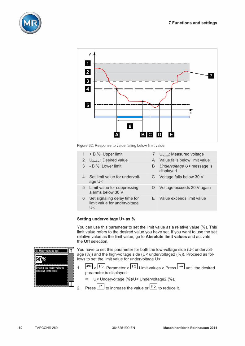
7 Functions and settings
Maschinenfabrik Reinhausen 201460 3643251/00 ENTAPCON® 260
Figure 32: Response to value falling below limit value
1 + B %: Upper limit 7 Uactual: Measured voltage2 Udesired: Desired value A Value falls below limit value3 - B %: Lower limit B Undervoltage U< message is
displayed4 Set limit value for undervolt-
age U<C Voltage falls below 30 V
5 Limit value for suppressingalarms below 30 V
D Voltage exceeds 30 V again
6 Set signaling delay time forlimit value for undervoltageU<
E Value exceeds limit value
Setting undervoltage U< as %
You can use this parameter to set the limit value as a relative value (%). Thislimit value refers to the desired value you have set. If you want to use the setrelative value as the limit value, go to Absolute limit values and activatethe Off selection.
You have to set this parameter for both the low-voltage side (U< undervolt-age (%)) and the high-voltage side (U< undervoltage2 (%)). Proceed as fol-lows to set the limit value for undervoltage U<:
1. > Parameter > Limit values > Press until the desiredparameter is displayed.ð U< Undervoltage (%)/U< Undervoltage2 (%).
2. Press to increase the value or to reduce it.

7 Functions and settings
Maschinenfabrik Reinhausen 2014 613643251/00 EN TAPCON® 260
3. Press .ð The limit value is set.
Setting undervoltage U< in V/kV
You can use this parameter to set the limit value as an absolute value in V or
kV units. If you use the key to change the display to kV, this value re-lates to the primary transformer voltage. If you change the display to V, thisrelates to the secondary voltage.
If you want to use the set absolute values as the limit value, go to Absolutelimit values and activate the On selection.
You have to set this parameter for both the low-voltage side (U< undervolt-age (V)) and the high-voltage side (U< undervoltage2 (V)). Proceed as fol-lows to set the absolute limit value for undervoltage U<:
1. > Parameter > Limit values > Press until the desiredparameter is displayed.ð U< Undervoltage (V)/U< Undervoltage2 (V).
2. If necessary press to select the unit you want, "V" or "kV".
3. Press to increase the value or to reduce it.
4. Press .ð The limit value is set.
Setting signaling delay time for undervoltage U<
You can use this parameter to set the delay time after which the Undervolt-age relay is to activate and the event message appear on the display. Thiscan be used to prevent messages from being issued when the value brieflyfalls below the limit value. The undervoltage LED always lights up immedi-ately regardless.
The parameter applies to regulation of both the low-voltage side and high-voltage side. Proceed as follows to set the delay time for this message:
1. > Parameter > Limit values > Press until the desiredparameter is displayed.ð U< Delay
2. Press to highlight the position.ð The desired position is highlighted and the value can be changed.
3. Press to increase the time or to reduce it.

7 Functions and settings
Maschinenfabrik Reinhausen 201462 3643251/00 ENTAPCON® 260
4. Press .ð The signaling delay time for undervoltage U< is set.
Activating/deactivating undervoltage blocking
You can use this parameter to set how the device behaves if the voltage fallsbelow the undervoltage limit. You can select the following options:
Setting FunctionOn Automatic regulation is blocked.Off Automatic regulation remains active.
Table 12: Behavior
The parameter applies to regulation of both the low-voltage side and high-voltage side. Proceed as follows to activate/deactivate the undervoltageblocking:
1. > Parameter > Limit values > Press until the desiredparameter is displayed.ð Blocking Undervolt. U<
2. Press for On setting or for Off setting.
3. Press .ð Undervoltage blocking is activated/deactivated.
Activating/deactivating message for voltages below 30 V
You can use this parameter to set whether the Undervoltage message is tobe suppressed at a measured value of less than 30 V. This setting is used toensure that no event message appears when the transformer is switched off.You can select the following options:
Setting FunctionOn The Undervoltage message is also displayed
when the measured value is less than 30 V.Off The Undervoltage message is no longer dis-
played when the measured value is less than30 V.
Table 13: Response
The parameter applies to regulation of both the low-voltage side and high-voltage side. Proceed as follows to activate/deactivate the message:
1. > Parameter > Limit values > Press until the desiredparameter is displayed.ð U< Also Below 30 V.
2. Press for On setting or for Off setting.

7 Functions and settings
Maschinenfabrik Reinhausen 2014 633643251/00 EN TAPCON® 260
3. Press .ð The message is activated/deactivated.
Setting overvoltage monitoring U>
You can use these parameters to set the limit values for overvoltage moni-toring. This overvoltage monitoring triggers tap-change operations to returnto the desired operating status. If the operating status can no longer be cor-rected, a message is triggered by the Function monitoring relay.
If the measured voltage Vactual exceeds the set limit value , the red LED V>and associated signaling relay activate (contact IO-X1:18/19 opens and IO-X1:18/20 closes). The Overvoltage V> message appears in the display. Atthe same time, the high-speed return function is activated without delay timeT1. Once the set switching pulse time has passed, the tap position is low-ered by activating the motor-drive unit until the measured voltage Vactual
again falls below the limit value . The Overvoltage V> message is re-set.
Figure 33: Response to limit value being exceeded
1 Set limit value for overvoltageV>
6 Vactual: Measured voltage
2 + B %: Upper limit A Value exceeds limit value3 Vdesired: Desired value B Value falls below limit value4 - B %: Lower limit C High-speed return is started
(lower tap-change)5 Set switching pulse time
7.7.3
Response to high-speedreturn

7 Functions and settings
Maschinenfabrik Reinhausen 201464 3643251/00 ENTAPCON® 260
The following sections describe how you can set the parameters for theovervoltage monitoring U> limit value.
Setting overvoltage U< as %
The limit value is entered as a relative value (%) of the set desired value.
You have to set this parameter for both the low-voltage side (U> overvoltage(%)) and the high-voltage side (U> overvoltage2 (%)). Proceed as follows toset the limit value:
1. > Parameter > Limit values > Press until the desiredparameter is displayed.ð U> Overvoltage (%) / U> Overvoltage2 (%).
2. Press to increase the value or to reduce it.
3. Press .ð The limit value is set.
Setting overvoltage U> in V/kV
You can use this parameter to set the limit value as an absolute value in V or
kV units. If you use the key to change the display to kV, this value re-lates to the primary transformer voltage. If you change the display to V, thisrelates to the secondary transformer voltage.
If you want to use the set absolute values as the limit value, go to Absolutelimit values and activate the On selection.
You have to set this parameter for both the low-voltage side (U> overvoltage(V)) and the high-voltage side (U> overvoltage2 (V)). Proceed as follows toset the absolute limit value for overvoltage U>:
1. > Parameter > Limit values > Press until the desiredparameter is displayed.ð U> Overvoltage (V) / U> Overvoltage2 (V).
2. If necessary press to select the unit you want, V or kV.
3. Press to increase the value or to reduce it.
4. Press .ð The limit value is set.
Setting overcurrent monitoring I>
You can use this parameter to set the limit value for overcurrent to preventtap-change operations in the event of excess load currents.
7.7.4

7 Functions and settings
Maschinenfabrik Reinhausen 2014 653643251/00 EN TAPCON® 260
If the measured current exceeds the set limit value, the red LED I> and as-sociated signaling relay activate. The Overcurrent blocking message ap-pears in the display. The device's output pulses are blocked at the sametime.
You have to enter the limit value as a relative value (%) of the current trans-
former's set nominal current. You can use the key to change the inputfrom a percentage % to absolute values in amps A. The percentage valuerelates to the nominal current. To change the input, the transformer data[ 71] must be set.
You have to set this parameter for both the low-voltage side (I> overcurrent)and the high-voltage side (I> overcurrent2). Proceed as follows to set thelimit value I> overcurrent for overcurrent blocking:
1. > Parameter > Limit values > Press until the desiredparameter is displayed.ð I> Overcurrent / I> Overcurrent2.
2. If necessary press to select the unit you want: % or A.
3. Press to increase the value or to reduce it.
4. Press .ð The limit value is set.
Activating/deactivating function monitoring
If the measured value leaves the current bandwidth (desired value +/- band-width) for more than 15 minutes without a tap-change operation taking place,the function monitoring relay is activated. This results in a message on thedisplay which is only reset when the measured value returns to within thecurrent bandwidth.
If the measured voltage is below 30 V, then the measured value is outsidethe bandwidth and the relevant relay is also activated after 15 minutes. Youcan deactivate this function if you want to avoid a function monitoring mes-sage when the transformer is switched off:
1. > Parameter > Limit values > Press until the desiredparameter is displayed.
2. Press or to select the option you want.
3. Press .ð Function monitoring is activated/deactivated.
Permitted tap positions
You can use the parameters described below to restrict the permissiblerange of tap positions in auto mode. If you activate this function, the devicedoes not switch to tap positions outside the set limits in auto mode.
7.7.5
7.7.6

7 Functions and settings
Maschinenfabrik Reinhausen 201466 3643251/00 ENTAPCON® 260
In manual mode, for manual tap changes on the motor-drive unit or for re-mote tap changes via a SCADA system, monitoring of the step limits is notactive. This may result in the set limits being exceeded.When switching from manual to auto mode, the tap changer should be with-in the permitted tap positions.
Setting minimum permitted tap position
You can use this parameter to set the minimum permitted tap position. To doso, proceed as follows:
1. Press > Parameter > Limit values > until the desiredparameter is displayed.ð Tap min.
2. Press to highlight the position.ð The desired position is highlighted and the value can be changed.
3. Press to increase the value or to reduce it.
4. Press .ð The minimum permitted tap position is set.
Setting the maximum permitted tap position
You can use this parameter to set the maximum permitted tap position. Todo so, proceed as follows:
1. Press > Parameter > Limit values > until the desiredparameter is displayed.ð Tap max.
2. Press to highlight the position.ð The desired position is highlighted and the value can be changed.
3. Press to increase the value or to reduce it.
4. Press .ð The maximum permitted tap position is set.
CompensationYou can use the compensation function to compensate for the load-depend-ent voltage drop between the transformer and consumer. The device pro-vides 2 methods of compensation for this purpose: Line drop compensation Z compensation
7.7.6.1
7.7.6.2
7.8

7 Functions and settings
Maschinenfabrik Reinhausen 2014 673643251/00 EN TAPCON® 260
Line drop compensation Z compensationMore accurate compensation Can only be used with minor
changes in the phase angle φFull knowledge of the line dataneeded
Is not dependent on phase angle φ
More parameters needed for con-figuration
Is simple to set
- Can be used with meshed net-works
Table 14: Comparison of methods of compensation
Line drop compensation
Line drop compensation (LDC) requires exact line data. Line voltage dropscan be compensated very accurately using LDC.
To set line drop compensation correctly, you need to calculate the ohmicand inductive voltage drop in V with reference to the secondary side of thevoltage transformer. You also need to correctly set the transformer circuitused.
Figure 36: Line drop compensation equivalent circuit
Figure 37: Illustration showing line drop compensation
7.8.1
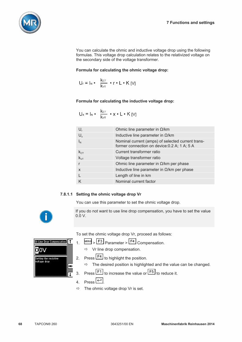
7 Functions and settings
Maschinenfabrik Reinhausen 201468 3643251/00 ENTAPCON® 260
You can calculate the ohmic and inductive voltage drop using the followingformulas. This voltage drop calculation relates to the relativized voltage onthe secondary side of the voltage transformer.
Formula for calculating the ohmic voltage drop:
Formula for calculating the inductive voltage drop:
Ur Ohmic line parameter in Ω/kmUx Inductive line parameter in Ω/kmIN Nominal current (amps) of selected current trans-
former connection on device:0.2 A; 1 A; 5 AkCT Current transformer ratiokVT Voltage transformer ratior Ohmic line parameter in Ω/km per phasex Inductive line parameter in Ω/km per phaseL Length of line in kmK Nominal current factor
Setting the ohmic voltage drop Vr
You can use this parameter to set the ohmic voltage drop.
If you do not want to use line drop compensation, you have to set the value0.0 V.
To set the ohmic voltage drop Vr, proceed as follows:
1. > Parameter > Compensation.ð Vr line drop compensation.
2. Press to highlight the position.ð The desired position is highlighted and the value can be changed.
3. Press to increase the value or to reduce it.
4. Press .ð The ohmic voltage drop Vr is set.
7.8.1.1

7 Functions and settings
Maschinenfabrik Reinhausen 2014 693643251/00 EN TAPCON® 260
Setting the inductive voltage drop Vx
You can use this parameter to set the inductive voltage drop. The compen-sation effect can be rotated by 180° in the display using a plus or minus sign.
If you do not want to use line drop compensation, you have to set the value0.0 V.
To set the inductive voltage drop Vx, proceed as follows:
1. > Parameter > Compensation > Press until the de-sired parameter is displayed.ð Vx line drop compensation.
2. Press to highlight the position.ð The desired position is highlighted and the value can be changed.
3. Press to increase the value or to reduce it.
4. Press .ð The inductive voltage drop Vx is set.
Z compensation
To keep the voltage constant for the consumer, you can use Z compensationto activate a current-dependent increase in voltage. Z compensation is notdependent on the phase angle φ and should only be used for small changesin phase angle.
You can also define a limit value to avoid excess voltage on the transformer.
Figure 38: Z compensation
To use Z compensation, you need to calculate the increase in voltage (ΔU)taking the current into account. Use the following formula for this purpose:
7.8.1.2
7.8.2

7 Functions and settings
Maschinenfabrik Reinhausen 201470 3643251/00 ENTAPCON® 260
∆U Voltage increase I Load current in AUTr Transformer voltage with
current IIN Nominal current of current
transformer connection in A(0.2 A; 1 A; 5 A )
ULoad Voltage on line end withcurrent I and on-load tap-changer in same operatingposition
kCT Current transformer ratio
Sample calculation: UTr = 100.1 V, ULoad = 100.0 V, IN = 5 A kCT = 200 A/5 A,I = 100 AProduces a voltage increase ∆U of 0.2%
The following sections describe how you can set the parameters you needfor Z compensation.
Setting Z compensation
This parameter sets the voltage increase ∆V previously calculated.
If you do not want to use Z compensation, you have to set the value 0.0 %.
To set the Z compensation, proceed as follows:
1. > Parameter > Compensation > Press until the de-sired parameter is displayed.ð Z compensation.
2. Press to increase the value or to reduce it.
3. Press .ð The Z compensation is set.
Setting the Z compensation limit value
You can use this parameter to define the maximum permissible voltage in-crease to avoid excess voltage on the transformer.
If you do not want to use a limit value, you have to set the value 0.0 %.
To set the limit value, proceed as follows:
7.8.2.1
7.8.2.2

7 Functions and settings
Maschinenfabrik Reinhausen 2014 713643251/00 EN TAPCON® 260
1. > Parameter > Compensation > Press until the de-sired parameter is displayed.ð Z comp. limit value.
2. Press to increase the value or to reduce it.
3. Press .ð The limit value is set.
Transformer dataThe transformation ratios and measuring set-up for the voltage and currenttransformers used can be set with the following parameters. The deviceuses this information to calculate the corresponding measured values on theprimary side of the current transformer (and therefore the transformer) fromthe recorded measured values. These are then displayed.
The following parameters are available for this purpose: Primary voltage Secondary voltage Primary current Secondary current (current transformer connection) Transformer circuit
The measured values displayed for the device are influenced by the settingsfor the above parameters. Note the table below.
Parameter set Measured value displayPrimaryvoltage
Secon-dary
voltage
Primarycurrent
Trans-former
connec-tion
Voltage (mainscreen)
Current(main screen)
Current (infoscreen)
- Yes - - Secondary volt-age [V]
- Secondary cur-rent [% of con-
nection]Yes Yes - - Primary voltage
[kV]- Secondary cur-
rent [% of con-nection]
Yes Yes Yes - Primary voltage[kV]
Primary cur-rent [A]
Secondary cur-rent [% of con-
nection]Yes Yes - Yes Primary voltage
[kV]- Secondary cur-
rent [A]Yes Yes Yes Yes Primary voltage
[kV]Primary cur-
rent [A]Secondary cur-
rent [A]Table 15: Influence of transformer data on measured value display
7.9

7 Functions and settings
Maschinenfabrik Reinhausen 201472 3643251/00 ENTAPCON® 260
Setting the primary transformer voltage
This parameter can be used to set the primary transformer voltage in kV.When you are setting the primary transformer voltage, the device shows theprimary voltage rather than the secondary voltage in the main screen andyou can also set the control parameters in kV.
If a setting of 0 kV is chosen, no primary transformer voltage is displayed.
You have to set this parameter for both the low-voltage side (primary volt-age) and the high-voltage side (primary voltage2). Proceed as follows to setthe primary transformer voltage:
1. > Configuration > Transformer data.ð Primary voltage/Primary voltage2.
2. Press to highlight the decimal place.ð The decimal place is defined and the value can be changed.
3. Press to highlight the position.ð The desired position is highlighted and the value can be changed.
4. Press to increase the value or to reduce it.
5. Press .ð The primary transformer voltage is set.
Setting the secondary transformer voltage
This parameter can be used to set the secondary transformer voltage in V.
You have to set this parameter for both the low-voltage side (secondary volt-age) and the high-voltage side (secondary voltage2). Proceed as follows toset the secondary transformer voltage:
1. > Configuration > Transformer data > Press until thedesired parameter is displayed.ð Secondary voltage/Secondary voltage2.
2. Press to highlight the position.ð The desired position is highlighted and the value can be changed.
3. Press to increase the value or to reduce it.
4. Press .ð The secondary transformer voltage is set.
7.9.1
7.9.2

7 Functions and settings
Maschinenfabrik Reinhausen 2014 733643251/00 EN TAPCON® 260
Setting primary transformer current
This parameter can be used to set the primary transformer current. When you are setting the primary transformer current, the measured
value is displayed in the main screen. If you set a value of 0, no measured value is displayed in the main
screen.
Setting parameter Current feed DisplayPrimary current Secondary cur-
rentPower connection Info screen
Primary/secon-dary current
Main screen
No parameteriza-tion
Unknown 1 A 100 % 0 A
No parameteriza-tion
1 A 1 A 1 A 0 A
50 A Unknown 1 A 100 % (of primarycurrent)
50 A (of primarycurrent)
50 A 1 A 1 A 1 A (of secondarycurrent)
50 A (of primarycurrent)
Table 16: Example of unit displayed: %/A
You have to set this parameter for both the low-voltage side (primary cur-rent) and the high-voltage side (primary current2). Proceed as follows to setthe primary transformer current:
1. > Configuration > Transformer data > Press until thedesired parameter is displayed.ð Primary current/Primary current2.
2. Press to highlight the position.ð The desired position is highlighted and the value can be changed.
3. Press to increase the value or to reduce it.
4. Press .ð The primary transformer current is set.
Setting the current transformer connection
This parameter can be used to set the current transformer connection. Thissetting is needed for the device to display the correct secondary current inthe info screen.
If you select the "Unknown" option, the percentage of current (with referenceto the current transformer connection used) is displayed in the info screen. 0.2 A
7.9.3
7.9.4

7 Functions and settings
Maschinenfabrik Reinhausen 201474 3643251/00 ENTAPCON® 260
1 A 5 A
You have to set this parameter for both the low-voltage side (current trans-former connection) and the high-voltage side (current transformer connec-tion2). Proceed as follows to set the current transformer connection:
1. > Configuration > Transformer data > Press until thedesired parameter is displayed.ð Current transformer connection/Current transformer connection2.
2. Press or to select the required connection terminal.
3. Press .ð The current transformer connection is set.
Setting the phase difference for the current transformer/voltagetransformer
You can use this parameter to set the phase difference of the current trans-former and voltage transformer. You can set the common transformer cir-cuits as follows:
Setting Measurement meth-od
Phase difference
0 1PH 1 phase 0°0 3PHN 3 phase 0°0 3PH 3 phase 0°90 3PH 3 phase 90°30 3PH 3 phase 30°-30 3PH 3 phase -30°
Table 17: Set values for transformer circuit
Note the following sample circuits to select the correct transformer circuit.
Circuit A: 1-phase measurement in 1-phase grid
TAPCON® 260
Figure 39: Phase difference 0 1PH
7.9.5

7 Functions and settings
Maschinenfabrik Reinhausen 2014 753643251/00 EN TAPCON® 260
The voltage transformer VT is connected to the outer conductor andneutral conductor.
The current transformer CT is looped into the outer conductor. The voltage VL1 and current IL1 are in phase. The voltage drop on an outer conductor is determined by the current IL1.
Circuit B: 1-phase measurement in 3-phase grid
TAPCON® 260
Figure 40: Phase difference 0 3PHN
The voltage transformer VT is connected to the outer conductors L1 andthe neutral conductor.
The current transformer CT is looped into the outer conductor L1. The voltage V and current I are in phase. The voltage drop on an outer conductor is determined by the current IL1.
Circuit C:
TAPCON® 260
Figure 41: Phase difference 0 3PHN
The voltage transformer VT is connected to the outer conductors L1 andL2.
The current transformer CT1 is looped into the outer conductor L1 andCT2 into the outer conductor L2.
The current transformers CT1 and CT2 are connected crosswise in par-allel (total current = IL1 + IL2).
The total current IL1 + IL2 and voltage VL1-VL2 are in phase.

7 Functions and settings
Maschinenfabrik Reinhausen 201476 3643251/00 ENTAPCON® 260
The voltage drop on an outer conductor is determined by the current:(IL1 + IL2) / √3.
Circuit D
TAPCON® 260
Figure 42: Phase difference 90 3PH
The voltage transformer VT is connected to the outer conductors L1 andL2.
The current transformer CT is looped into the outer conductor L3. The current IL3 is ahead of voltage VL1-VL2 by 90°. The voltage drop on an outer conductor is determined by the current IL3.
Circuit E
TAPCON® 260
Figure 43: Phase difference 30 3PH
The voltage transformer VT is connected to the outer conductors L1 andL2.
The current transformer CT is looped into the outer conductor L2. The current IL2 is ahead of voltage VL2-VL1 by 30°. The voltage drop on an outer conductor is determined by the current IL2.

7 Functions and settings
Maschinenfabrik Reinhausen 2014 773643251/00 EN TAPCON® 260
Circuit F
TAPCON® 260
Figure 44: Phase difference -30 3PH
The voltage transformer VT is connected to the outer conductors L1 andL2.
The current transformer CT is looped into the outer conductor L1. The current IL1 lags behind VL1-VL2 by 30°. This corresponds to a phase
shift of -30°. The voltage drop on an outer conductor is determined by the current IL1.
The parameter applies to both the high-voltage side and low-voltage side ofthe transformer. Proceed as follows to set the phase difference for the trans-former circuit:
1. > Configuration > Transformer data > Press until thedesired parameter is displayed.ð W1/W2 transformer circuit.
2. Press or to select the required phase difference.
3. Press .ð The phase difference is set.
Parallel operationIn the Parallel operation menu item, you can set the parameters needed forparallel transformer operation. Parallel transformer operation is used to in-crease the throughput capacity or short-circuit capacity in one place.
Compliance with the following general conditions is required for operatingtransformers in parallel: Identical rated voltages Transformer power ratio (< 3 : 1) Maximum deviation of short-circuit voltages (UK) for transformers con-
nected in parallel < 10% Same number of switching groups
7.10
Conditions for paralleloperation
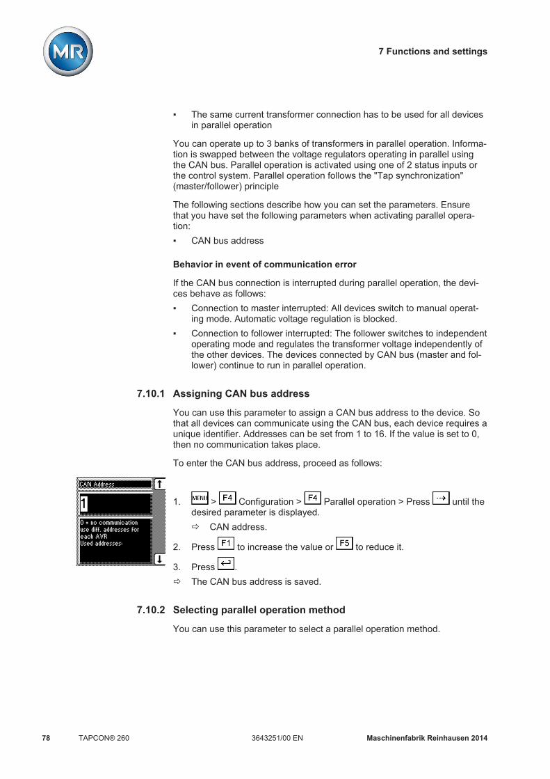
7 Functions and settings
Maschinenfabrik Reinhausen 201478 3643251/00 ENTAPCON® 260
The same current transformer connection has to be used for all devicesin parallel operation
You can operate up to 3 banks of transformers in parallel operation. Informa-tion is swapped between the voltage regulators operating in parallel usingthe CAN bus. Parallel operation is activated using one of 2 status inputs orthe control system. Parallel operation follows the "Tap synchronization"(master/follower) principle
The following sections describe how you can set the parameters. Ensurethat you have set the following parameters when activating parallel opera-tion: CAN bus address
Behavior in event of communication error
If the CAN bus connection is interrupted during parallel operation, the devi-ces behave as follows: Connection to master interrupted: All devices switch to manual operat-
ing mode. Automatic voltage regulation is blocked. Connection to follower interrupted: The follower switches to independent
operating mode and regulates the transformer voltage independently ofthe other devices. The devices connected by CAN bus (master and fol-lower) continue to run in parallel operation.
Assigning CAN bus address
You can use this parameter to assign a CAN bus address to the device. Sothat all devices can communicate using the CAN bus, each device requires aunique identifier. Addresses can be set from 1 to 16. If the value is set to 0,then no communication takes place.
To enter the CAN bus address, proceed as follows:
1. > Configuration > Parallel operation > Press until thedesired parameter is displayed.ð CAN address.
2. Press to increase the value or to reduce it.
3. Press .ð The CAN bus address is saved.
Selecting parallel operation method
You can use this parameter to select a parallel operation method.
7.10.1
7.10.2

7 Functions and settings
Maschinenfabrik Reinhausen 2014 793643251/00 EN TAPCON® 260
The "circulating reactive current minimization" parallel operation methoddoes not work. The device only supports the "Master/follower" parallel oper-ation method.
The following sections describe how you can set the parameters for a paral-lel operation method.
Setting tap synchronization
With the tap synchronization method, you need to designate one voltageregulator as the master and all others as followers. The master handles volt-age regulation and transmits its current tap positions to all followers via theCAN bus. The followers compare the tap position received with their own tapposition. If the set permissible tap difference between the tap position re-ceived and their own position is exceeded, the followers switch to the tap po-sition received from the master. This ensures that the transformers operatingin parallel are always in the same tap position.
For the tap synchronization method, you can select the following options:
Option DescriptionMaster The voltage regulator is designated as the master.Follower The voltage regulator is designated as the follower.Sync.auto Automatic assignment of master or follower.
If no master is detected, the voltage regulator with thelowest CAN bus address is automatically designatedas the master. All other voltage regulators are desig-nated as followers.
Table 18: Tap synchronization method
In order to use the sync.auto option, an individual CAN bus address mustbe assigned to each voltage regulator. Up to 16 CAN participants are sup-ported.
To set the tap synchronization method, proceed as follows:
1. > Configuration > Parallel operation.ð Parallel operation method.
2. Press or to select the option you want.
3. Press .ð The tap synchronization method is selected.
7.10.2.1

7 Functions and settings
Maschinenfabrik Reinhausen 201480 3643251/00 ENTAPCON® 260
Setting delay time for parallel operation error messages
You can use this parameter to set the delay time for a parallel operation er-ror message so that brief fault messages are not received if the motor-driveunits involved in the parallel operation have different runtimes. Once the setdelay time has elapsed, the event is issued at the output relay. Automaticregulation is blocked and the on-load tap-changers can only be adjusted inmanual mode.
To set the delay time for the parallel operation error message, proceed asfollows:
1. > Configuration > Parallel operation > Press until thedesired parameter is displayed.ð Error message.
2. Press to increase the value or to reduce it.
3. Press .ð The delay time for the parallel operation error message is set.
Deactivating parallel operation
To deactivate parallel operation, proceed as follows:
1. > Configuration > Parallel operation.ð Parallel operation method.
2. Press or to deactivate parallel operation with the Off selection.
3. Press .ð Parallel operation is deactivated.
Analog tap position capture (optional)For the analog tap position capture, you must assign the lowest tap positionto the analog input for the minimum measured value and the highest tap po-sition for the maximum measured value.
The device is configured at the factory according to the order. However,should modifications be necessary, note the following sections.
The analog input card is used to record the tap position of an analog signaltransmitter. Depending on device configuration, you can capture the follow-ing signals:
AD card AD8 cardResistor contact series 200...2,000 ohms not possible
7.10.3
7.10.4
7.11

7 Functions and settings
Maschinenfabrik Reinhausen 2014 813643251/00 EN TAPCON® 260
AD card AD8 cardInjected current 0/4...20 mA 0/4...20 mA
Table 19: Analog tap position capture
Setting lower limit value
You can use these parameters to set the lower limit value for the tap posi-tion . To do this, you must set the lower value of the signal range and thelinked lowest tap position.
You can undertake the settings for each input on the analog input card.
For example: To capture a tap position range of 1...19 via input 1 as4...20 mA, you must set 20 % for the "Input 1 lower limit" parameter and 1.0for the "Input 1 lower value" parameter.
Setting lower limit value of input signal
To configure the analog input, you must state the lower limit value of the in-put signal. Use the following settings depending on your analog signal:
Analog signal SettingInjected current: 0...20 mA 0 % (= 0 mA)Injected current: 4...20 mA 20 % (= 4 mA)Resistor contact series always 20 %
Table 20: Parameter settings
To set the lower limit value of the input, proceed as follows:
1. > Configuration > Continue > Analog inputs.ð Input 1 lower limit.
2. Press to highlight the position.ð The desired position is highlighted and the value can be changed.
3. Press to increase the value or to reduce it.
4. Press .ð The lower limit value for the tap position is assigned.
Setting lower value of input signal
To configure the analog input, an absolute value must be assigned to thelower value of the applied signal.
To set the lower value for the input, proceed as follows:
7.11.1

7 Functions and settings
Maschinenfabrik Reinhausen 201482 3643251/00 ENTAPCON® 260
1. > Configuration > Continue > Analog inputs > Press
until the desired parameter is displayed.ð Input 1 lower value.
2. Press to increase the value or to reduce it.
3. Press .ð The lower value for the tap position is assigned.
Setting upper limit value
You can use parameters to set the upper value for the tap position. To dothis, you must set the upper value of the signal range and linked highest tapposition.
You can undertake the settings for each input on the analog input card.
For example: To capture a tap position range of 1...19 via input 1 as4...20 mA, you must set 100 % for the "Input 1 upper limit" parameter and19.0 for the "Input 1 upper value" parameter.
Setting upper limit value of input signal
To configure the analog input, you must state the upper limit value for the in-put signal. Use the following settings depending on your analog signal:
Analog signal SettingInjected current: 0/4...20 mA 100 % (= 20 mA)Resistor contact series always 100 %
Table 21: Parameter settings
To set the upper limit value for the input, proceed as follows:
1. > Configuration > Continue > Analog inputs > Press
until the desired parameter is displayed.ð Input 1 upper limit.
2. Press to highlight the position.ð The desired position is highlighted and the value can be changed.
3. Press to increase the value or to reduce it.
4. Press .
Setting upper value of input signal
To configure the analog input, an absolute value must be assigned to the up-per value of the applied signal.
To set the upper value for the input, proceed as follows:
7.11.2

7 Functions and settings
Maschinenfabrik Reinhausen 2014 833643251/00 EN TAPCON® 260
1. > Configuration > Continue > Analog inputs > Press
until the desired parameter is displayed.ð Input 1 upper value.
2. Press to increase the value or to reduce it.
3. Press .
Measuring transducer functionDepending on the configuration and version of the measuring transducermodule 2 or 4, the transducer module can be used to obtain measured val-ues as analog values in the following ranges: ± 20 mA ± 10 mA ± 10 V (only AN2 card) ± 1 mA
The following values are available: V1 V2 (optional via a second measurement input) I1 Active current Reactive current Active power Reactive power Apparent power Tap position Desired value
If the analog outputs have not been set as you want them in the factory, thesection below describes how you can adjust the measuring transducer.
Assigning measurement parameter of outputs 1 to 4
In this display you can assign a measurement parameter to be transferred tothe measuring transducer output.
7.12
7.12.1

7 Functions and settings
Maschinenfabrik Reinhausen 201484 3643251/00 ENTAPCON® 260
In order to assign a measurement parameter to the measuring transduceroutput, proceed as follows (example using measuring transducer 1/2; "output1 measured value"):
1. > Configuration > Continue > Continue > Meas-uring transducer 1/2.ð Output 1 measured value.
2. Press or until the desired measurement parameter is dis-played.
3. Press .ð The desired measurement parameter is assigned.
Assigning minimum physical parameter
In this display you can assign a minimum physical parameter to the measur-ing transducer output.
To assign the lower physical parameter to the measuring transducer, pro-ceed as follows:
1. Press > Configuration > Continue > Continue >
Measuring transducer 1 / 2 > until the desired parameter is dis-played.ð Output 1 bottom.
2. Press or until the desired physical parameter is displayed.
3. Press .ð The desired physical parameter is assigned.
Assigning maximum physical parameter
In this display you can assign a maximum physical parameter to the measur-ing transducer output.
To assign the upper physical parameter to the measuring transducer, pro-ceed as follows:
1. Press > Configuration > Continue > Continue >
Measuring transducer 1 / 2 > until the desired parameter is dis-played.ð Output 1 top.
2. Press or until the desired physical parameter is displayed.
3. Press .ð The desired physical parameter is assigned.
7.12.2
7.12.3

7 Functions and settings
Maschinenfabrik Reinhausen 2014 853643251/00 EN TAPCON® 260
Assigning minimum absolute value
In this display you can assign a minimum limit value to the measuring trans-ducer output as an absolute value.
To assign the minimum absolute value, proceed as follows:
1. > Configuration > Continue > Continue > Meas-
uring transducer 1 / 2 > Press until the desired parameter is dis-played.ð Output 1 lower value.
2. Press to increase the value or to reduce it.
3. Press .ð The minimum absolute value is assigned.
Assigning maximum absolute value
In this display you can assign a maximum limit value to the measuring trans-ducer output as an absolute value.
To assign the maximum absolute value, proceed as follows:
1. > Configuration > Continue > Continue > Meas-
uring transducer 1 / 2 > Press until the desired parameter is dis-played.ð Output 1 upper value.
2. Press to increase the value or to reduce it.
3. Press .ð The minimum absolute value is assigned.
Communication interfaceThe following section describes how to configure the communication inter-face with SCADA.
Assigning network address
You can use this parameter to assign a network address to the device.
To assign a network address, proceed as follows:
7.12.4
7.12.5
7.13
7.13.1

7 Functions and settings
Maschinenfabrik Reinhausen 201486 3643251/00 ENTAPCON® 260
1. Press > Configuration > General > until the desiredparameter is displayed.ð Network address.
2. Press in order to highlight the position.ð The desired position is highlighted and the value can be changed.
3. Press to increase the value or to reduce it.
4. Press .ð The network address is assigned.
Assigning a network mask
You can use this parameter to set the network mask.
Be sure to enter a valid network mask that is not 0.0.0.0, otherwise it will notbe possible to connect to the device.
To assign a network mask, proceed as follows:
1. Press > Configuration > General > until the desiredparameter is displayed.ð Network mask.
2. Press in order to highlight the position.ð The desired position is highlighted and the value can be changed.
3. Press to increase the value or to reduce it.
4. Press .ð The network mask is assigned.
Entering the time server address
This parameter lets you enter the IP address of a SNTP time server. If youare using a time server, the device uses the time of the time server as thesystem time.
Be sure to enter a valid time server address that is not 0.0.0.0, otherwise itwill not be possible to connect to the device.
To enter the time server address of the SNTP server, proceed as follows:
7.13.2
7.13.3

7 Functions and settings
Maschinenfabrik Reinhausen 2014 873643251/00 EN TAPCON® 260
1. Press > Configuration > General > until the desiredparameter is displayed.ð Time server address.
2. Press in order to highlight the position.ð The desired position is highlighted and the value can be changed.
3. Press to increase the value or to reduce it.
4. Press .ð The time server IP address is entered.
Entering gateway
You can use this parameter to set the gateway's IP address.
If you set the value to 0.0.0.0, no gateway is used.
To enter the gateway address, proceed as follows:
1. Press > Configuration > General > until the desiredparameter is displayed.ð Gateway.
2. Press in order to highlight the position.ð The desired position is highlighted and the value can be changed.
3. Press to increase the value or to reduce it.
4. Press .ð The gateway address is entered.
Entering IED name
You can use this parameter to assign the device an IED name in order for itto be identified in the IEC 61850 network.
The IED name must start with a letter and may contain no more than 11characters.
To enter the IED name, proceed as follows:
7.13.4
7.13.5

7 Functions and settings
Maschinenfabrik Reinhausen 201488 3643251/00 ENTAPCON® 260
1. Press > Configuration > General > until the desiredparameter is displayed.ð IED name.
2. Press in order to highlight the position.ð The desired position is highlighted and the value can be changed.
3. Press to increase the value or to reduce it.
4. Press .ð The IED name is entered.
Displaying information about deviceThe next section describes how you can display information about the de-vice.
Displaying the info screen
Information about the device can be viewed here.
The following information is displayed: Device model Firmware version number Serial number RAM Additional cards
To display the info screen, proceed as follows:
> Infoð Info.
Displaying measured values
The current measured values are shown in this display. The following meas-ured values can be displayed:
To display the measured values, proceed as follows:
7.14
7.14.1
7.14.2

7 Functions and settings
Maschinenfabrik Reinhausen 2014 893643251/00 EN TAPCON® 260
> Info > Press until the desired measurement parameteris displayed.
ð Measured values.
Carrying out LED test
You can check whether the LEDs are functioning properly. To do this, pressthe relevant function key to illuminate an LED:
Key LED no.
... LED 1...LED 5
+ ... + LED 6...LED 9
All LEDs
Table 22: Arrangement of keys for the LED test
This function will only test the functional reliability of the respective LED.The function of the device linked to the LED is not tested.
To carry out the LED test, proceed as follows:
1. > Info > Press until the desired measurement parameteris displayed.ð LED test.
2. To carry out the function test, press any F key for the LED you want totest.
Displaying input/output status
The status of the respective optocoupler inputs is shown in the INPUT /OUTPUT-STATUS display. As soon as a continuous signal is present at theinput, it is shown in the display with a 1. 0 indicates no signal at the input.
7.14.3
7.14.4

7 Functions and settings
Maschinenfabrik Reinhausen 201490 3643251/00 ENTAPCON® 260
Figure 50: Signals
1 Signaling status 2 Control inputs/output relays
To query the status, proceed as follows:
Press > Info > until the desired measurement parameteris displayed.
ð INPUT/OUTPUT STATUS.
Displaying UC card status
The status of the respective optocoupler inputs is shown in this display . Assoon as a continuous signal is present at the input, it is shown in the displaywith a 1. 0 indicates no signal at the input.
Figure 51: UC card signals
1 Signaling status 2 Control inputs
To query the status, proceed as follows:
Press > Info > until the desired measurement parameteris displayed.
ð UC1 CARD STATUS/UC2 CARD STATUS.
7.14.5

7 Functions and settings
Maschinenfabrik Reinhausen 2014 913643251/00 EN TAPCON® 260
Resetting parameters
With this display you can reset your settings to the factory settings . It alsoshows whether all parameters are saved correctly.
Resetting the parameters to the factory settings permanently deletes yoursettings.
To reset all the set parameters, proceed as follows:
1. Press > Info > until the desired measurement parameteris displayed.ð Parameters.
2. Press and at the same time.
3. Press .ð All parameters have been reset to the factory settings.
Displaying real-time clock
An operations counter is started when the device is first switched on. Thiscontinues to run even if the device is switched off. Each of the operationscounter's times is overwritten with that of the PC to visualize the measuredvalues.
To display the real-time clock, proceed as follows:
Press > Info > until the desired measurement parameteris displayed.
ð RTC.
Displaying parallel operation
This display indicates the regulator number (CAN bus address) for paralleloperation and the number of voltage regulators which are currently operatingin parallel.
To display the parallel operation data, proceed as follows:
> Info > Press until the desired display appears.ð Parallel operation.
Displaying data on CAN bus
The CAN bus data of the connected devices is shown in this display.
7.14.6
7.14.7
7.14.8
7.14.9

7 Functions and settings
Maschinenfabrik Reinhausen 201492 3643251/00 ENTAPCON® 260
Figure 52: CAN bus data
1 CAN bus address of device 4 Reactive current in %2 Voltage in V 5 Current tap position3 Active current in %
Figure 53: Other CAN bus data
1 Group input 1 5 Follower tap synchronization(0 = deactivated; 1 = activat-ed)
2 Group input 2 6 Auto tap synchronization (0 =deactivated; 1 = activated)
3 Circulating reactive currentparallel operation (0 = deacti-vated; 1 = activated)
7 Device blocks group becauseparallel operation is experi-encing a fault (0 = is notblocked; 1 = is blocked)
4 Master tap synchronization (0= deactivated; 1 = activated)
To display the CAN bus data, proceed as follows:
1. Press > Info > until the desired measurement parameteris displayed.ð DATA ON CAN BUS.
2. Press and hold to display more data.ð The additional information is displayed until you release the key.

7 Functions and settings
Maschinenfabrik Reinhausen 2014 933643251/00 EN TAPCON® 260
Displaying peak memory
The display shows the minimum and maximum tap position since the last re-set.
The minimum and maximum values continue to be stored in an internalfixed value memory even in the event of power failure.
To display the peak memory, proceed as follows:
> Info > Press until the desired measurement parameteris displayed.
ð Peak memory.
Displaying upcoming messages
This display shows upcoming messages, such as: Undervoltage Overvoltage Fault in parallel operation etc.
To display the upcoming messages, proceed as follows:
Press > Info > until the desired measurement parameteris displayed.
ð UPCOMING MESSAGES
7.14.10
7.14.11
8 Control system protocol
Maschinenfabrik Reinhausen 201494 3643251/00 ENTAPCON® 260
Control system protocol
Protocol specificationThe device provides an extract of commands and messages from the inter-face protocol IEC 61850 for communication.
You can find the device-specific data points and presettings in the device'sICD file. You can request the following documents for the device or down-load from the device: MICS (Model Implementation Conformance Statement) PICS (Protocol Implementation Conformance Statement) PIXIT (Protocol Implementation eXtra Information for Testing) TICS (Technical Issues Conformance Statement)
Please note possible restrictions and comments regarding device specificdata points and default settings listed in the documents above.
Downloading ICD file
You can download the ICD file via FTP from the device. You have to estab-lish an ethernet connection between the device and your PC.
For a smooth download with Windows Vista/7/8 operating systems, useWindows Explorer.
Proceed as follows to download the ICD file:1. Enter ftp://gast@<IP adress> in your browser (in the example in
the diagram below, the IP adress is 192.168.0.1) and select the directo-ry home/gast.
8
8.1
Device-specific data points
8.1.1

8 Control system protocol
Maschinenfabrik Reinhausen 2014 953643251/00 EN TAPCON® 260
2. If necessary, confirm the password prompt without entering a password.
Figure 54: Downloading the ICD file using an Internet browser
3. Use Save as to download the ICD file (in this example ATCC.ICD).4. Other files, such as the Model Implementation Conformance Statement,
are located in the misc folder and can also be downloaded using Saveas.
Data pointsYou will find these abbreviations in the following tables.
N no / not availableY yes / availableM mandatoryO optionalC conditional
LPHD - Physical device
Attribute name Attributetype
Explanation M/O/E Remarks
LPHD - Physical device information M -DataCommon logical node informationPhyNam DPL Physical device name plate M -PhyHealth INS Physical device health M -
8.2
8.2.1

8 Control system protocol
Maschinenfabrik Reinhausen 201496 3643251/00 ENTAPCON® 260
Attribute name Attributetype
Explanation M/O/E Remarks
Proxy SPS Indicates if this LN is a proxy M -Table 23: LPHD class (LPHD1)
LLN0 - Logical node
Attribute name Attributetype
Explanation M/O/E Remarks
LLN0 - Logical node zero name - -DataCommon logical node informationMod ENC Mode M Status onlyBeh INS Behavior M -Health INS Health M -NamPlt LPL Name plate M -
Table 24: LLNO class
ATCC1 - Automatic tap changer controller
Attribute name Attributetype
Explanation M/O/E Remarks
ATCC1 - AVR - -Common logical node informationMod INC Mode M status-onlyBeh INS Behavior M -Health INS 1:=OK; 2:=function monitoring; 3:=no in-
ternal communication or parameter errorM -
NamPlt LPL Name plate M -ControlsTapChg BSC Change tap position C direct-with-
normal-se-curity
ParOp DPC Parallel independent M direct-with-normal-se-
curityLTCBlk SPC Block automatic control O direct-with-
normal-se-curity
Master SPC Master mode (parallel control) E direct-with-normal-se-
curityFollower SPC Follower mode (parallel control) E direct-with-
normal-se-curity
8.2.2
8.2.3

8 Control system protocol
Maschinenfabrik Reinhausen 2014 973643251/00 EN TAPCON® 260
Attribute name Attributetype
Explanation M/O/E Remarks
SICmd1 SPC Serial interface command 1 E direct-with-normal-se-
curitySICmd2 SPC Serial interface command 2 E direct-with-
normal-se-curity
SICmd3 SPC Serial interface command 3 E direct-with-normal-se-
curityBndCtrEna1 SPC Band center 1 enable (low or high voltage
side)E direct-with-
normal-se-curity
BndCtrEna2 SPC Band center 2 enable (low or high voltageside)
E direct-with-normal-se-
curityBndCtrEna3 SPC Band center 3 enable (low or high voltage
side)E direct-with-
normal-se-curity
Measured valuesCtlV MV Control voltage 1, U1 M -CtlV2 MV Control voltage 2, U2 (high voltage side) E -LodA MV Load current (percentage of nominal load
current), I1 (low voltage side)O -
LodA2 MV Load current 2 (percentage of nominalload current), I2 (high voltage side)
E -
Status informationLoc SPS Local operation M -Auto SPS Automatic manual O -CtlHiVSel SPS Control voltage 2 (high voltage side) se-
lected (OFF=U1, ON=U2)E -
RvPwrFlw SPS Reverse power flow E -TapDif SPS Tap difference between YLTC1, YLTC2,
YLTC3E -
OverV1 SPS U1 high limit reached E -OverV2 SPS U2 high limit reached E -UnderV1 SPS U1 low limit reached E -UnderV2 SPS U2 low limit reached E -OverC1 SPS Current overload I1 E -OverC2 SPS Current overload I2 E -MotDrv SPS Motor drive running E -UInd1 SPS User indication 1 E -UInd2 SPS User indication 2 E -UInd3 SPS User indication 3 E -

8 Control system protocol
Maschinenfabrik Reinhausen 201498 3643251/00 ENTAPCON® 260
Attribute name Attributetype
Explanation M/O/E Remarks
UInd4 SPS User indication 4 E -FuncMon SPS Function monitoring E -ParErr SPS Parameter error E -SettingsBndCtr ASG Band center voltage (actual reference),
only readableO -
BndCtrLV1 ASG Band center voltage 1 (low voltage side) E -BndCtrLV2 ASG Band center voltage 2 (low voltage side) E -BndCtrLV3 ASG Band center voltage 3 (low voltage side) E -BndCtrHiV1 ASG Band center voltage 1 (high voltage side) E -BndCtrHiV2 ASG Band center voltage 2 (high voltage side) E -BndCtrHiV3 ASG Band center voltage 3 (high voltage side) E -BndWid ASG Band width voltage (as percent of nominal
voltage)O -
CtlDlTmms ING Control intentional time delay ( in sec-onds)
O -
LDCR ASG Line drop voltage due to line resistancecomponent (voltage)
O -
LDCX ASG Line drop voltage due to line reactancecomponent (voltage)
O -
BlkLV ASG Control voltage below which auto lowercommands blocked (relative)
O -
LimLodA ASG Limit load current (LTC block load current,percentage)
O -
LimLodA2 ASG Limit load current 2 (LTC block load cur-rent, percentage of I2)
E -
LDC SPG Line drop compensation is R and X or Zmodel (0=R and X, 1=Z compensation)
O -
TmDlChr SPG Time delay linear or inverse characteristic(0=lin., 1=inv.)
O -
LDCZ ASG Line drop voltage due to line total impe-dance (percentage of nominal voltage)
O -
TapBlkR ING Tap position of on-load tap changerwhere automatic raise commands areblocked
O -
TapBlkL ING Tap position of on-load tap changerwhere automatic lower commands areblocked
O -
Table 25: ATCC1 - Automatic tap changer controller

8 Control system protocol
Maschinenfabrik Reinhausen 2014 993643251/00 EN TAPCON® 260
YLTC1 - Tap Changer
Attribute name Attributetype
Explanation M/O/E Remarks
YLTC1 - OLTC - -Common logical node informationMod INC Mode M status-onlyBeh INS Behavior M -Health INS 1:=OK; 2:=signaling YELLOW for
TAPGUARD; 3:=no internal communica-tion or parameter error or signaling REDfor TAPGUARD
M -
NamPlt LPL Name plate M -ControlsTapChg BSC Change tap position C direct-with-
normal-se-curity
Measured values- - - - -Status informationEndPosR SPS End position raise reached M -EndPosL SPS End position lower reached M -MotDrv SPS Motor drive running E -MotProt SPS Motor drive protective relay trip status E -Settings- - - - -
Table 26: YLTC class
YLTC2 - Tap Changer
Attribute name Attributetype
Explanation M/O/E Remarks
YLTC2 - OLTC - -Common logical node informationMod INC Mode M status-onlyBeh INS Behavior M -Health INS 1:=OK; 2:=signaling YELLOW for
TAPGUARD; 3:=no internal communica-tion or parameter error or signaling REDfor TAPGUARD
M -
NamPlt LPL Name plate M -ControlsTapChg BSC Change tap position C direct-with-
normal-se-curity
8.2.4
8.2.5

8 Control system protocol
Maschinenfabrik Reinhausen 2014100 3643251/00 ENTAPCON® 260
Attribute name Attributetype
Explanation M/O/E Remarks
Measured values- - - - -Status informationEndPosR SPS End position raise reached M -EndPosL SPS End position lower reached M -MotDrv SPS Motor drive running E -MotProt SPS Motor drive protective relay trip status E -Settings- - - - -
Table 27: YLTC class
YLTC3 - Tap Changer
Attribute name Attributetype
Explanation M/O/E Remarks
YLTC3 - OLTC - -Common logical node informationMod INC Mode M status-onlyBeh INS Behavior M -Health INS 1:=OK; 2:=signaling YELLOW for
TAPGUARD; 3:=no internal communica-tion or parameter error or signaling REDfor TAPGUARD
M -
NamPlt LPL Name plate M -ControlsTapChg BSC Change tap position C direct-with-
normal-se-curity
Measured values- - - - -Status informationEndPosR SPS End position raise reached M -EndPosL SPS End position lower reached M -MotDrv SPS Motor drive running E -MotProt SPS Motor drive protective relay trip status E -Settings- - - - -
Table 28: YLTC class
8.2.6

8 Control system protocol
Maschinenfabrik Reinhausen 2014 1013643251/00 EN TAPCON® 260
GPIO IO - Generic process I/O
Attribute name Attributetype
Explanation M/O/E Remarks
GGIO1 - GPIO IO - -Common logical node informationMod INC Mode M status-onlyBeh INS Behavior M -Health INS 1:=OK; 3:=no internal communication M -NamPlt LPL Name plate M -Controls- - - - -Measured values- - - - -Status informationInd1 SPS IO X1:31 E -Ind2 SPS IO X1:33 E -Ind3 SPS IO X1:16 E -Ind4 SPS IO X1:17 E -Ind5 SPS IO X1:14 E -Ind6 SPS IO X1:13 E -Ind7 SPS IO X1:11 E -Ind8 SPS IO X1:12 E -Ind9 SPS IO X1:29 E -Ind10 SPS IO X1:28 E -Ind11 SPS IO X1:4/5 E -Ind12 SPS IO X1:6/7 E -Ind13 SPS IO X1:8/9 E -Ind14 SPS IO X1:18/19/20 E -Ind15 SPS IO X1:21/22 E -Ind16 SPS IO X1:23/24 E -Ind17 SPS IO X1:25/26 E -Settings- - - - -
Table 29: GGIO class
GPIO UC1 - Generic process I/O
Attribute name Attributetype
Explanation M/O/E Remarks
GGIO2 - GPIO UC1 - -Common logical node informationMod INC Mode M status-only
8.2.7
8.2.8

8 Control system protocol
Maschinenfabrik Reinhausen 2014102 3643251/00 ENTAPCON® 260
Attribute name Attributetype
Explanation M/O/E Remarks
Beh INS Behavior M -Health INS 1:=OK; 3:=no internal communication M -NamPlt LPL Name plate M -Controls- - - - -Measured values- - - - -Status informationInd1 SPS UC1 X1:11 E -Ind2 SPS UC1 X1:12 E -Ind3 SPS UC1 X1:14 E -Ind4 SPS UC1 X1:15 E -Ind5 SPS UC1 X1:16 E -Ind6 SPS UC1 X1:17 E -Ind7 SPS UC1 X1:30 E -Ind8 SPS UC1 X1:31 E -Ind9 SPS UC1 X1:32 E -Ind10 SPS UC1 X1:33 E -Ind11 SPS UC1 X1:1/2 E -Ind12 SPS UC1 X1:3/4 E -Ind13 SPS UC1 X1:5/6 E -Ind14 SPS UC1 X1:7/8 E -Ind15 SPS UC1 X1:9/10 E -Ind16 SPS UC1 X1:18/19 E -Ind17 SPS UC1 X1:20/21 E -Ind18 SPS UC1 X1:22/23 E -Ind19 SPS UC1 X1:24/25 E -Ind20 SPS UC1 X1:26/27 E -Settings- - - - -
Table 30: GGIO class
GPIO UC2 - Generic process I/O
Attribute name Attributetype
Explanation M/O/E Remarks
GGIO3 - GPIO UC2 - -Common logical node informationMod INC Mode M status-onlyBeh INS Behavior M -
8.2.9

8 Control system protocol
Maschinenfabrik Reinhausen 2014 1033643251/00 EN TAPCON® 260
Attribute name Attributetype
Explanation M/O/E Remarks
Health INS 1:=OK; 3:=no internal communication M -NamPlt LPL Name plate M -Controls- - - - -Measured values- - - - -Status informationInd1 SPS UC2 X1:11 E -Ind2 SPS UC2 X1:12 E -Ind3 SPS UC2 X1:14 E -Ind4 SPS UC2 X1:15 E -Ind5 SPS UC2 X1:16 E -Ind6 SPS UC2 X1:17 E -Ind7 SPS UC2 X1:30 E -Ind8 SPS UC2 X1:31 E -Ind9 SPS UC2 X1:32 E -Ind10 SPS UC2 X1:33 E -Ind11 SPS UC2 X1:1/2 E -Ind12 SPS UC2 X1:3/4 E -Ind13 SPS UC2 X1:5/6 E -Ind14 SPS UC2 X1:7/8 E -Ind15 SPS UC2 X1:9/10 E -Ind16 SPS UC2 X1:18/19 E -Ind17 SPS UC2 X1:20/21 E -Ind18 SPS UC2 X1:22/23 E -Ind19 SPS UC2 X1:24/25 E -Ind20 SPS UC2 X1:26/27 E -Settings- - - - -
Table 31: GGIO class
GPIO UC3 - Generic process I/O
Attribute name Attributetype
Explanation M/O/E Remarks
GGIO4 - GPIO UC3 - -Common logical node informationMod INC Mode M status-onlyBeh INS Behavior M -Health INS 1:=OK; 3:=no internal communication M -
8.2.10

8 Control system protocol
Maschinenfabrik Reinhausen 2014104 3643251/00 ENTAPCON® 260
Attribute name Attributetype
Explanation M/O/E Remarks
NamPlt LPL Name plate M -Controls- - - - -Measured values- - - - -Status informationInd1 SPS UC3 X1:11 E -Ind2 SPS UC3 X1:12 E -Ind3 SPS UC3 X1:14 E -Ind4 SPS UC3 X1:15 E -Ind5 SPS UC3 X1:16 E -Ind6 SPS UC3 X1:17 E -Ind7 SPS UC3 X1:30 E -Ind8 SPS UC3 X1:31 E -Ind9 SPS UC3 X1:32 E -Ind10 SPS UC3 X1:33 E -Ind11 SPS UC3 X1:1/2 E -Ind12 SPS UC3 X1:3/4 E -Ind13 SPS UC3 X1:5/6 E -Ind14 SPS UC3 X1:7/8 E -Ind15 SPS UC3 X1:9/10 E -Ind16 SPS UC3 X1:18/19 E -Ind17 SPS UC3 X1:20/21 E -Ind18 SPS UC3 X1:22/23 E -Ind19 SPS UC3 X1:24/25 E -Ind20 SPS UC3 X1:26/27 E -Settings- - - - -
Table 32: GGIO class
GPIO UC4 - Generic process I/O
Attribute name Attributetype
Explanation M/O/E Remarks
GGIO5 - GPIO UC4 - -Common logical node informationMod INC Mode M status-onlyBeh INS Behavior M -Health INS 1:=OK; 3:=no internal communication M -NamPlt LPL Name plate M -
8.2.11

8 Control system protocol
Maschinenfabrik Reinhausen 2014 1053643251/00 EN TAPCON® 260
Attribute name Attributetype
Explanation M/O/E Remarks
Controls- - - - -Measured values- - - - -Status informationInd1 SPS UC4 X1:11, motor drive local, AVR block-
ingE -
Ind2 SPS UC4 X1:12 E -Ind3 SPS UC4 X1:14, reclosing in process sys A,
AVR blockingE -
Ind4 SPS UC4 X1:15, reclosing in process sys B,AVR blocking
E -
Ind5 SPS UC4 X1:16 E -Ind6 SPS UC4 X1:17 E -Ind7 SPS UC4 X1:30 E -Ind8 SPS UC4 X1:31 E -Ind9 SPS UC4 X1:32 E -Ind10 SPS UC4 X1:33 E -Ind11 SPS UC4 X1:1/2 E -Ind12 SPS UC4 X1:3/4 E -Ind13 SPS UC4 X1:5/6 E -Ind14 SPS UC4 X1:7/8 E -Ind15 SPS UC4 X1:9/10 E -Ind16 SPS UC4 X1:18/19 E -Ind17 SPS UC4 X1:20/21 E -Ind18 SPS UC4 X1:22/23 E -Ind19 SPS UC4 X1:24/25 E -Ind20 SPS UC4 X1:26/27 E -Settings- - - - -
Table 33: GGIO class

9 Fault elimination
Maschinenfabrik Reinhausen 2014106 3643251/00 ENTAPCON® 260
Fault eliminationThis chapter describes how to eliminate simple operating faults.
General faultsCharacteristics/detail Cause RemedyNo function Operating status LED
does not illuminate
No power supply Check the power supplyFuse tripped Contact Maschinenfabrik Reinhausen
GmbHRelays chatter Supply voltage too low Check the supply voltage
High EMC load Use shielded cables or external filtersPoor grounding Check the functional ground
Table 34: General faults
No regulation in AUTO modeCharacteristics/detail Cause RemedyDevice control commandshave no effect. RAISE/LOWER LEDs
light up periodically
LOCAL/REMOTE switch inmotor-drive unit switched toLOCAL.
Check operating mode and switch to RE-MOTE if necessary.
No connection Check wiring as per connection diagram.Device blocking Negative power flow Check current-transformer polarity.
Control inputs have duplicateparameterization.
Check parameterization of control inputs.A function may only be assigned to onecontrol input.
A control input is parameter-ized with blocking and a sig-nal is present at this controlinput.
Check parameterization and status ofcontrol input under Info (Input/Output Sta-tus). If necessary, change parameteriza-tion or deactivate signal source.
NORMset is active, but hasnot been commissioned cor-rectly
Activate operating mode and performa manual tap-change operation using
keys or . Then activate operating
mode .Device blocking U< LED lights up
Undervoltage blocking active Check parameters
Device blocking U> LED lights up
Overvoltage blocking active Check parameters
Device blocking I> LED lights up
Overcurrent blocking active Check parameters
Bandwidth set too high - Determine recommended bandwidth[ 51] and set parameters.
9
9.1
9.2

9 Fault elimination
Maschinenfabrik Reinhausen 2014 1073643251/00 EN TAPCON® 260
Characteristics/detail Cause RemedyDevice blocking The Circuit breaker pos.
invalid event message isactive.
Automatic winding selectionactive and circuit breaker po-sition invalid
Check the tap winding parameter.Check the position of the circuit breakers.
Table 35: No regulation in AUTO mode
Man-machine interfaceCharacteristics/detail Cause RemedyKeys MANUAL/AUTO operat-
ing mode cannot bechanged
REMOTE operating mode
active and LED in key il-luminated.
Press to activate LOCAL mode.
Keys
LEDs in keys and
not illuminated.
Parameter error Reset parameters to factory settings[ 91].
Display No display.
Contrast incorrectly set. Set contrast [ 35].Voltage supply interrupted. Check voltage supply.Fuse faulty. Contact Maschinenfabrik Reinhausen.
LEDs Freely configurable LED
lights up
Customized LED parameteri-zation.
Check parameters.
LEDs LED flashing
Input signal not constant. Check input signal.
COM1 Cannot be connected to
PC using TAPCON®-trol.
Different baud rates set. Check baud rate set on device and PC.
Table 36: Man-machine interface
Incorrect measured valuesCharacteristics/detail Cause RemedyMeasured voltage No measured value.
Connection has no contact inthe plug terminal.
Check wiring and plug terminal.
Insulation trappedWire not inserted far enough.Circuit breaker tripped. Check fuse.
Measured voltage Measured value too low.
Voltage drop on measuringlead.
Check measured voltage at plug terminalMI:01/MI:02.
Measured voltage Possible sources of fault: Leads laid in parallel.
Check measured voltage at plug terminalMI:01/MI:02.
9.3
9.4

9 Fault elimination
Maschinenfabrik Reinhausen 2014108 3643251/00 ENTAPCON® 260
Characteristics/detail Cause Remedy Measured value fluctu-
ates. Tap-change operations. Increase distance from source of interfer-
ence.Install filter if necessary.
Measured current No measured value.
Line to current transformerinterrupted.
Check wiring.
Short-circuiting jumper incurrent transformer not re-moved.
Remove short-circuiting jumper.
Measured current Measured value too
high. Measured value too low.
Transmission ratio not cor-rectly parameterized.
Correct parameterization.
Incorrect input connected. Remove short-circuiting jumper.
Phase angle V/I.
Fault in external transformercircuit.
Check transformer circuit.
Transformer circuit incorrect-ly parameterized.
Compare with system connection dia-gram.Correct parameters.Compare measurement values on infoscreen.Transpose current transformer connec-tion.Check polarity of transformer circuit.Correct if necessary.Check circuit.Correct if necessary.Check measurement points.Correct if necessary.
Table 37: Incorrect measured values
Parallel operation faultsCharacteristics/detail Cause RemedyParallel operation cannot beactivated. LED not lit up.
"Parallel operation method"parameter deactivated.
Set parallel operation method parameters.
CAN bus address of deviceset to "0".
Set CAN bus address (anything but 0).
Problem with CAN bus. Device not listed.
Device incorrectly connected(plug twisted, offset).
Check connections.Connect as shown in connection diagram.
Devices have the same CANbus addresses.
Set different CAN bus addresses.
Table 38: Parallel operation faults
9.5
9 Fault elimination
Maschinenfabrik Reinhausen 2014 1093643251/00 EN TAPCON® 260
Tap position capture incorrectCharacteristics/detail Cause RemedyStep display incorrect. Plus or minus sign incor-
rect
Incorrect wiring. Check wiring.Connect as shown in connection diagram.
Minimum value of analog in-put signal not correctly para-meterized.
Check parameters.Set "Analog Val. [%] Tap Pos. Min." pa-rameter.
Step display incorrect. Display fluctuates.
Interference. Shield the line.Increase distance from source of interfer-ence.Lay interference lines separately.Route signal in separate lines (filter,shielded lines).
No step display. "-" is displayed.
No measurement signal.No L- for digital input.
Connect signal as shown in connection di-agram.Check wiring.Review status screen.Connect as shown in connection diagram.
No step display. "?" is displayed.
Bit combination (code) im-permissible.
Check wiring.Review status screen.
"Motor running" signal pres-ent.
Check signal sequenceReview status screen.
Table 39: Tap position capture
Other faultsIf you cannot resolve a problem, please contact Maschinenfabrik Reinhau-sen. Please have the following data to hand: Serial number
This can be found: Outer right side when viewed from the front
Info screen ( > Info)
Please provide answers to the following questions: Has a firmware update been carried out? Has there previously been a problem with this device? Have you previously contacted Maschinenfabrik Reinhausen about this
issue? If yes, then who was the contact?
9.6
9.7

10 Messages
Maschinenfabrik Reinhausen 2014110 3643251/00 ENTAPCON® 260
MessagesThis chapter contains an overview of the device's messages.
Signal inputsInput Inscription FunctionIO-X1:28 PARALLEL GROUP
1Assign parallel operation group 1
IO-X1:29 PARALLEL GROUP2
Assign parallel operation group 2
IO-X1:31 MOTOR DRIVEUNIT LOCAL
Motor-drive unit in "Local" oper-ating mode, manual Raise/Lowertap-change operations not possi-ble via TAPCON® 260 controls
IO-X1:33 MASTER Select "Master" parallel operationmethod
IO-X1:16 FOLLOWER Select "Follower" parallel opera-tion method
IO-X1:17 INDEPENDENT Deactivate parallel operationIO-X1:12 AUTO Activate AUTO modeIO-X1:11 MANUAL Activate MANUAL modeIO-X1:13 RAISE Raise tap positionIO-X1:14 LOWER Lower tap positionUC1/2/3-X1:14...17,UC1/2/3-X1:30...33
BCD1…BCD20,BCD+, BCD-
BCD tap input signal
UC1/2/3-X1:11
MOTOR PROTEC-TIVE SWITCH OFF
Motor protective switch triggered
UC1/2/3-X1:12
MOTOR DRIVEUNIT IN OPERA-TION
Motor running
UC4-X1:11 MOTOR DRIVE LO-CAL, AVR BLOCK-ING
Voltage regulation blocked
UC4-X1:14 RECLOSING INPROCESS SYS A,AVR BLOCKED
Voltage regulation blocked
UC4-X1:15 RECLOSING INPROCESS SYS A,AVR BLOCKED
Voltage regulation blocked
Table 40: Signal inputs
10
10.1

10 Messages
Maschinenfabrik Reinhausen 2014 1113643251/00 EN TAPCON® 260
Signal outputsRelay Inscription CauseIO-X1:02/03
STATUS Status message
IO-X1:23 PARALLEL FAIL-URE
Signal for parallel operation error mes-sage
IO-X1:25 PARALLEL ON Signal if parallel operation is activeIO-X1:21 FUNCTION
MONITORINGSignal for Function monitoring mes-sage
IO-X1:10 AUTO Signal if auto mode is activeIO-X1:09 MANUAL Signal if manual mode is activeIO-X1:06 TAP DIFFER-
ENCESignal in event of bank of transformershaving tap position difference
IO-X1:20 U<, U>, I> Signal for undervoltage, overvoltage,overcurrent message
UC1/2/3-X1:02
LOWER Reduce voltage
UC1/2/3-X1:04
RAISE Increase voltage
UC1/2/3-X1:06...10,UC1/2/3-X1:19...23
TAP POSITIONBCD1…BCD20
BCD signal of tap position
UC1/2/3-X1:25
MOTOR PRO-TECTIVESWITCH OFF
Signal if motor protective switch Q1 hastriggered
UC1/2/3-X1:27
MOTOR RUN-NING
Signal if motor is running
UC4-X1:02 REGULATIONON HV SIDE
Signal if control on high-voltage sideactive
UC4-X1:04 REGULATIONON LV SIDE
Signal if control on low-voltage side ac-tive
UC4-X1:06 REGULATIONAUTO
Signal if automatic voltage regulationactive
UC4-X1:08 REVERSE POW-ER FLOW
Signal if negative power flow
Table 41: Signal outputs
Event messagesEvent message CauseUndervoltage Event message appears if value falls below un-
dervoltage limit value.Overvoltage Event message appears if value exceeds over-
voltage limit value.
10.2
10.3
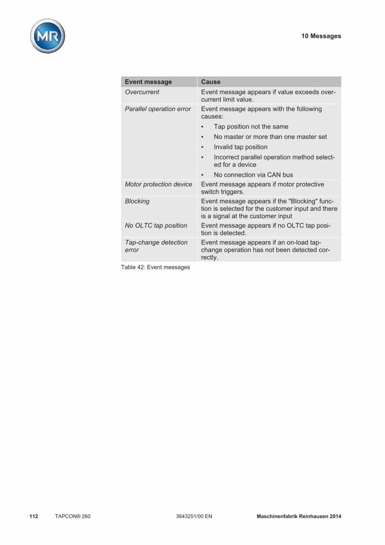
10 Messages
Maschinenfabrik Reinhausen 2014112 3643251/00 ENTAPCON® 260
Event message CauseOvercurrent Event message appears if value exceeds over-
current limit value.Parallel operation error Event message appears with the following
causes: Tap position not the same No master or more than one master set Invalid tap position Incorrect parallel operation method select-
ed for a device No connection via CAN bus
Motor protection device Event message appears if motor protectiveswitch triggers.
Blocking Event message appears if the "Blocking" func-tion is selected for the customer input and thereis a signal at the customer input
No OLTC tap position Event message appears if no OLTC tap posi-tion is detected.
Tap-change detectionerror
Event message appears if an on-load tap-change operation has not been detected cor-rectly.
Table 42: Event messages

11 Disposal
Maschinenfabrik Reinhausen 2014 1133643251/00 EN TAPCON® 260
DisposalThe device was produced in accordance with European Community Direc-tive 2011/65/EC (RoHS) and must be disposed of accordingly. If the deviceis not operated within the European Union, the national disposal require-ments applicable in the country of use should be observed.
11

12 Overview of parameters
Maschinenfabrik Reinhausen 2014114 3643251/00 ENTAPCON® 260
Overview of parametersThis section contains an overview of the relevant menus and parameters.
Parameter Setting range Factory setting Current settingParameter > NormsetNormset activation On/Off Off Desired value 1 49...140 V 100 V Primary voltage 0...9,999 kV 220 kV Secondary voltage 57...125 V 100 V Winding2 desired value 1 49...140 V 100 V Primary voltage2 0...9,999 kV 400 kV Secondary voltage2 57...125 V 100 V Parameter > Control parameterDesired value 1 49...140 V 100.0 V Desired value 2 49...140 V 100.0 V Desired value 3 49...140 V 100.0 V Bandwidth 0.5...9 % 1.00 % Winding2 desired value 1 49...140 V 100.0 V Winding2 desired value 2 49...140 V 100.0 V Winding2 desired value 3 49...140 V 100.0 V T1 delay time 0...600 s 40 s T1 control response T1 linear/T1 integral T1 linear T2 activation T2 on/T2 off T2 off T2 delay time 1...60 s 10.0 s Parameter > Limit valuesAbsolute limit values On/Off Off U< Undervoltage (%) 60...100 % 90 % U< Undervoltage (V) 34...160 V 90.0 V U> Overvoltage (%) 100...140 % 110.0 % U> Overvoltage (V) 34...160 V 110.0 V I> Overcurrent 50...210 % 110 % U< Undervoltage2 (%) 60...100 % 90 % U< Undervoltage2 (V) 34...160 V 90.0 V U> Overvoltage2 (%) 100...140 % 110.0 % U> Overvoltage2 (V) 34...160 V 110.0 V I> Overcurrent2 50...210 % 110 % Fct. Monitoring On/Off Off U< Blocking On/Off On U< Delay 0...20 s 10.0 s U< also under 30 V On/Off Off Tap max. -128...128 40
12

12 Overview of parameters
Maschinenfabrik Reinhausen 2014 1153643251/00 EN TAPCON® 260
Parameter Setting range Factory setting Current settingTap min. -128...128 1 Parameter > CompensationUr line drop comp. -25...25 V 0.0 V Ux line drop comp. -25...25 V 0.0 V Z comp. limit value 0...15 % 0.0 % Z compensation 0...15 % 0.0 % Configuration > Transformer dataPrimary voltage 0...9,999 kV 220 kV Secondary voltage 57...125 V 100.0 V Primary current 0...9,999 A 1000 A Current transformer connec-tion
Unknown; 0.2 A; 1 A;5 A
1 A
Transformer circuit See [ 74] 0 3PH Primary voltage2 0...9,999 kV 400 kV Secondary voltage2 57...125 V 100.0 V Primary current2 0...9,999 A 1000 A Current transformer connec-tion2
Unknown; 0.2 A; 1 A;5 A
1 A
Configuration > GeneralLanguage See [ 36] English Regulator ID - 0000 COM1 setting 9.6 kilobaud; 19.2 kilo-
baud; 38.4 kilobaud;57.6 kilobaud
57.6 kilobaud
Display kV / V kV/V V Display %/ A On/Off Off R/L pulse duration 0...10 s 1.5 s Display dark On/Off On Motor runtime 0...30 s 10.0 s Network mask 0.0.0.0...255.255.255.
2550.0.0.0
Network address 0.0.0.0...255.255.255.255
0.0.0.0
Time server address 0.0.0.0...255.255.255.255
0.0.0.0
Gateway 0.0.0.0...255.255.255.255
0.0.0.0
IED name - MR01 Configuration > Parallel operationParallel operation method Off, circulating reactive
current; master; follow-er; synch. auto
Master

12 Overview of parameters
Maschinenfabrik Reinhausen 2014116 3643251/00 ENTAPCON® 260
Parameter Setting range Factory setting Current settingCAN address 0...16 1 Error message 1...99 s 10 s Tapping direction swapped Standard, Swapped Standard Configuration > Analog inputsInput 1 upper limit 0...100 % 100.0 % Input 1 lower limit 0...100 % 0.0 % Input 1 upper value -999.9...999.9 0.0 Input 1 lower value -999.9...999.9 0.0 Input 2 upper limit 0...100 % 0.0 % Input 2 lower limit 0...100 % 0.0 % Input 2 upper value -999.9...999.9 0.0 Input 2 lower value -999.9...999.9 0.0 Configuration > Measuring transducer 1/2Output 1 measured value See [ 83] Off Output 1 upper value -9,999...9,999 0 Output 1 lower value -9,999...9,999 0 Output 1 upper 1 mA; 10 mA; 20 mA;
N/A20 mA
Output 1 lower See [ 84] +4 mA Output 2 measured value See [ 83] Off Output 2 upper value -9,999...9,999 0 Output 2 lower value -9,999...9,999 0 Output 2 upper 1 mA; 10 mA; 20 mA;
N/A20 mA
Output 2 lower See [ 84] +4 mA Configuration > Measuring transducer 3/4Output 3 measured value See [ 83] Off Output 3 upper value -9,999...9,999 0 Output 3 lower value -9,999...9,999 0 Output 3 upper 1 mA; 10 mA; 20 mA;
10 V20 mA
Output 3 lower See [ 84] +4 mA Output 4 measured value See [ 83] Off Output 4 upper value -9,999...9,999 0 Output 4 lower value -9,999...9,999 0 Output 4 upper 1 mA; 10 mA; 20 mA;
10 V20 mA
Output 4 lower See [ 84] +4 mA Configuration > ReverseHV control if reverse P On/Off Off Minimum current 0...100 % 0 %

12 Overview of parameters
Maschinenfabrik Reinhausen 2014 1173643251/00 EN TAPCON® 260
Parameter Setting range Factory setting Current settingChange delay 0...60 s 5 s Change sw.dir. if reverse P On/Off Off No line comp. if reverse P On/Off Off Minimum current blocking On/Off Off MI inp.1 if I < min. On/Off Off Block if reverse P On/Off Off
Table 43: Overview of parameters

13 Technical data
Maschinenfabrik Reinhausen 2014118 3643251/00 ENTAPCON® 260
Technical data
Indicator elementsDisplay LCD, monochrome, graphics-capable
128 x 128 pixelsLEDs 15 LEDs for operation display and messages
Table 44: Indicator elements
Assemblies
CPU card
Figure 55: CPU card
1 CAN bus interface
IO card
Inputs OutputsInput Terminal Output Contact
type*Terminal
E1 IO-X1:11-15 A1 NO IO-X1:25-26E2 IO-X1:12-15 A2 NO IO-X1:23-24E3 IO-X1:13-15 A3 NO IO-X1:23-22E4 IO-X1:14-15 A4 NO IO-X1:18-20
NC IO-X1:18-19E5 IO-X1:16-27 A5 NO IO-X1:8-10
NC IO-X1:8-9E6 IO-X1:17-27 A6 NO IO-X1:6-7
NC IO-X1:4-5E7 IO-X1:28-30 A7 NO IO-X1:1-3
NC IO-X1:1-2
13
13.1
13.2
13.2.1
13.2.2
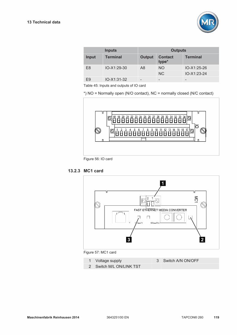
13 Technical data
Maschinenfabrik Reinhausen 2014 1193643251/00 EN TAPCON® 260
Inputs OutputsInput Terminal Output Contact
type*Terminal
E8 IO-X1:29-30 A8 NO IO-X1:25-26NC IO-X1:23-24
E9 IO-X1:31-32 - - -Table 45: Inputs and outputs of IO card
*) NO = Normally open (N/O contact), NC = normally closed (N/C contact)
Figure 56: IO card
MC1 card
Figure 57: MC1 card
1 Voltage supply 3 Switch A/N ON/OFF2 Switch M/L ON/LINK TST
13.2.3

13 Technical data
Maschinenfabrik Reinhausen 2014120 3643251/00 ENTAPCON® 260
Power supply 85...264 V AC; 110 V DC, 220 V DC47...63 HzPower consumption approx. 6 WInsulation 4.242 V DC
Temperaturerange
Operation: 0...40 °CStorage: -20...85 °C
Optical fiber Connection type: F-STFiber type: MultimodeMax. cable length: 2 kmWave length: 1310 nm
Table 46: MC1 card
MI card
Figure 58: MI card
SID card
Interface ModelEthernet RJ45 socket, 100 MBit/s LAN
Table 47: SID card
Figure 59: SID card
13.2.4
13.2.5

13 Technical data
Maschinenfabrik Reinhausen 2014 1213643251/00 EN TAPCON® 260
SU card
Input Voltage range TerminalL1 / + DC 88...350 V DC
88...265 V AC*SU-X1:01
N / -DC 88...350 V DC88...265 V AC*
SU-X1:02
Table 48: SU card inputs (standard model)
*) Permissible frequency range: 45…65 Hz
Input Voltage range Terminal+ DC 18...36 V DC SU-X1:01-DC 18...36 V DC SU-X1:02
or+ DC 36...72 V DC SU-X1:01- DC 36...72 V DC SU-X1:02
Table 49: Inputs for the SU card come in a 18...36 V DC version or a 36...72 V DCversion
Figure 60: SU card
UC card
Inputs OutputsInput Terminal Output Contact
type*Terminal
E1 UC1-X1:11-13 A1 NO UC1-X1:01-02E2 UC1-X1:12-13 A2 NO UC1-X1:03-04E3 UC1-X1:33-34 A3 NO UC1-X1:05-06E4 UC1-X1:32-34 A4 NO UC1-X1:07-08E5 UC1-X1:31-34 A5 NO UC1-X1:09-10E6 UC1-X1:30-34 A6 NO UC1-X1:18-19E7 UC1-X1:17-29 A7 NO UC1-X1:20-21
13.2.6Standard model
Special model
13.2.7
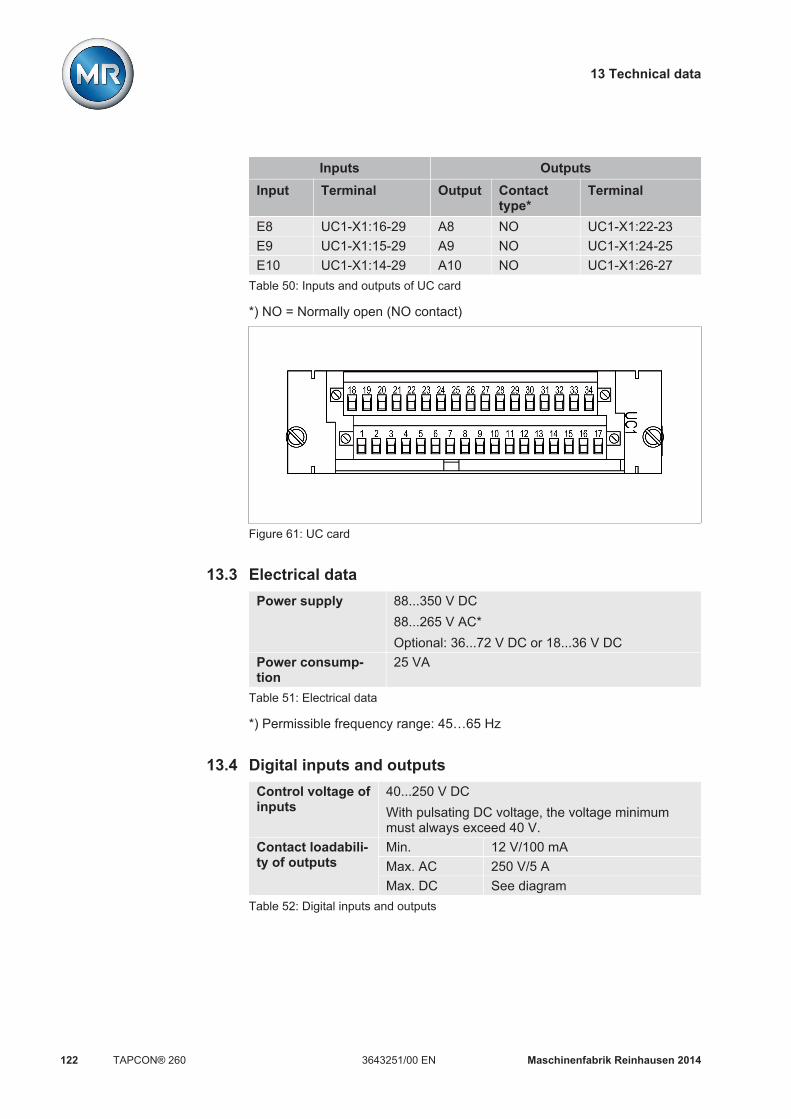
13 Technical data
Maschinenfabrik Reinhausen 2014122 3643251/00 ENTAPCON® 260
Inputs OutputsInput Terminal Output Contact
type*Terminal
E8 UC1-X1:16-29 A8 NO UC1-X1:22-23E9 UC1-X1:15-29 A9 NO UC1-X1:24-25E10 UC1-X1:14-29 A10 NO UC1-X1:26-27
Table 50: Inputs and outputs of UC card
*) NO = Normally open (NO contact)
Figure 61: UC card
Electrical dataPower supply 88...350 V DC
88...265 V AC*Optional: 36...72 V DC or 18...36 V DC
Power consump-tion
25 VA
Table 51: Electrical data
*) Permissible frequency range: 45…65 Hz
Digital inputs and outputsControl voltage ofinputs
40...250 V DCWith pulsating DC voltage, the voltage minimummust always exceed 40 V.
Contact loadabili-ty of outputs
Min. 12 V/100 mAMax. AC 250 V/5 AMax. DC See diagram
Table 52: Digital inputs and outputs
13.3
13.4

13 Technical data
Maschinenfabrik Reinhausen 2014 1233643251/00 EN TAPCON® 260
Figure 62: Maximum contact loadability of outputs with direct current
1 Ohmic load
Analog inputs and outputsAnalog recordingof measured val-ues (AD8 card, op-tional)
8 measuring inputs 4...20 mAMeasuring error ≤ 0.5 %
Analog signal out-put (AN card, op-tional)
2 outputs 0...20 mA or 4...20 mA2 outputs 0...20 mA, 4...20 mA or 0...10 V
Table 53: Analog inputs and outputs
Dimensions and weightHousing(W x H x D)
19-inch plug-in housing in accordance with DIN41494 Part 5483 x 133 x 178 mm (19 x 5.2 x 7 in)
Weight 5.0 kg (11 lb)Table 54: Dimensions and weight
13.5
13.6

13 Technical data
Maschinenfabrik Reinhausen 2014124 3643251/00 ENTAPCON® 260
Figure 63: Dimensions
Voltage measurement and current measurementVoltage measur-ing input
Measuring range: 49...140 VEffective value: 45...65 HzIntrinsic consumption: < 1 VA
13.7
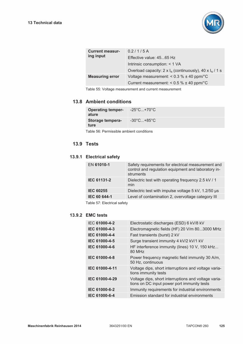
13 Technical data
Maschinenfabrik Reinhausen 2014 1253643251/00 EN TAPCON® 260
Current measur-ing input
0.2 / 1 / 5 AEffective value: 45...65 HzIntrinsic consumption: < 1 VAOverload capacity: 2 x IN (continuously), 40 x IN / 1 s
Measuring error Voltage measurement: < 0.3 % ± 40 ppm/°CCurrent measurement: < 0.5 % ± 40 ppm/°C
Table 55: Voltage measurement and current measurement
Ambient conditionsOperating temper-ature
-25°C...+70°C
Storage tempera-ture
-30°C...+85°C
Table 56: Permissible ambient conditions
Tests
Electrical safetyEN 61010-1 Safety requirements for electrical measurement and
control and regulation equipment and laboratory in-struments
IEC 61131-2 Dielectric test with operating frequency 2.5 kV / 1min
IEC 60255 Dielectric test with impulse voltage 5 kV, 1.2/50 μsIEC 60 644-1 Level of contamination 2, overvoltage category III
Table 57: Electrical safety
EMC testsIEC 61000-4-2 Electrostatic discharges (ESD) 6 kV/8 kVIEC 61000-4-3 Electromagnetic fields (HF) 20 V/m 80...3000 MHzIEC 61000-4-4 Fast transients (burst) 2 kVIEC 61000-4-5 Surge transient immunity 4 kV/2 kV/1 kVIEC 61000-4-6 HF interference immunity (lines) 10 V, 150 kHz...
80 MHzIEC 61000-4-8 Power frequency magnetic field immunity 30 A/m,
50 Hz, continuousIEC 61000-4-11 Voltage dips, short interruptions and voltage varia-
tions immunity testsIEC 61000-4-29 Voltage dips, short interruptions and voltage varia-
tions on DC input power port immunity testsIEC 61000-6-2 Immunity requirements for industrial environmentsIEC 61000-6-4 Emission standard for industrial environments
13.8
13.9
13.9.1
13.9.2

13 Technical data
Maschinenfabrik Reinhausen 2014126 3643251/00 ENTAPCON® 260
DIN EN 55011,DIN EN 55022
Emission "RFI"
Table 58: EMC tests
Environmental durability testsDIN EN 60529 Degree of protection IP20IEC 60068-2-1 Dry cold - 25 °C / 96 hoursIEC 60068-2-2 Dry heat + 70 °C/ 96 hoursIEC 60068-2-3 Constant moist heat
+ 40 °C / 93 % / 4 days, no dewIEC 60068-2-30 Cyclic moist heat (12 + 12 hours)
+ 55 °C / 93 % / 6 cyclesTable 59: Environmental durability tests
13.9.3

Glossary
Maschinenfabrik Reinhausen 2014 1273643251/00 EN TAPCON® 260
GlossaryDIN
Abbreviation for "Deutsches Institut für Normung"
ENAbbreviation for "European Norm"
IECInternational Electrotechnical Commission
LDCLine drop compensation
R/LRaise/lower
RTCAbbreviation for "Real Time Clock"

List of key words
Maschinenfabrik Reinhausen 2014128 3643251/00 ENTAPCON® 260
List of key wordsAAnalog input 80Assemblies
CPU card 22IO card 22MC1 card 22MI card 22SID card 22SU card 22UC card 22
BBandwidth 51
Calculation 51Visual display 52
Baud rate 40Block if reverse P 58
CCable recommendation 27CAN bus 78
Data 91Change delay 56Change sw.dir. if reverse P 57COM1 setting 40Compensation 66
Z compensation 69Connection 27Contrast 35Control parameter
Desired value 50Control parameters 48Control response T1 53CPU card 22
DDate 36Delay time T1 53Delay time T2 54
Activating 55Deactivating 55
Desired value 47Desired value 50
Device ID 40Display contrast 35Display dimming 44Display elements
LED 19
EElectromagnetic compatibility 29
FFactory setting 91, 114Fiber-optic cable
Information about laying 29Function monitoring 65
GGateway 87
HHigh-speed return 63HV control if reverse P 55
IICD file 94IEC 61850 94IED name 87Info 88Input 1 lower limit 81Input 1 lower value 81Input 1 upper limit 82Input 1 upper value 82Interface Protocol
IEC 61850 94IO card 22
KKey lock 39Keys 17
LLanguage 36Limit value
Absolute 58Limit value monitoring 58Overvoltage V> 63Relative 58Undervoltage U< 59
Line drop compensationInductive voltage drop 69Ohmic voltage drop 68
Line drop compensation 67
MMC1 card 22Measured values 88Measuring transducer 83MI card 22MI inp.1 if I < min. 58Min.current block 57Minimum current 56Motor runtime 44
Output relay 44
NNetwork address 85Network mask 86No line comp. if reverse P 57NORMset 46
OOperating controls 17Operating mode
Auto mode 16Local mode 16Manual mode 16Remote mode 16
Overcurrent I> 64Overview of parameters 114Overvoltage U>
Relative 64Overvoltage V> 63
Absolute 64
PParallel operation 77, 91
CAN bus 78Parallel operation error mes-
sage 80Parallel operation method 78
ParameterBandwidth 51
Peak memory 93Phase difference 74Primary voltage 46

List of key words
Maschinenfabrik Reinhausen 2014 1293643251/00 EN TAPCON® 260
RRaise/Lower pulse duration 42Regulator ID 40Reset parameters 91Reverse 55RTC 91
SSecondary voltage 47Short-circuit capacity 77SID card 22SNTP time server 86SU card 22
TTap max. 66Tap min. 66tap position capture
Analog 80Throughput capacity 77Time 36Time server address 86Transformer
Primary current 73Transformer data 71
Current transformer connection 73
Primary voltage 72Secondary voltage 72Transformer circuit 74
UUC card 22UC card status 90Undervoltage blocking
Absolute 61Relative 60
Upcoming messages 93
VV< also below 30 V 62V< blocking 62V< delay 61Voltage display kV/V 41Voltage regulation
High-voltage side 55Low-voltage side 55
WWiring 34
ZZ compensation 69
Activate 70Limit value 70


MR worldwideAustraliaReinhausen Australia Pty. Ltd.17/20-22 St Albans RoadKingsgrove NSW 2208Phone: +61 2 9502 2202Fax: +61 2 9502 2224E-Mail: [email protected]
BrazilMR do Brasil Indústria Mecánica Ltda.Av. Elias Yazbek, 465CEP: 06803-000Embu - São PauloPhone: +55 11 4785 2150Fax: +55 11 4785 2185E-Mail: [email protected]
CanadaReinhausen Canada Inc.3755, rue Java, Suite 180Brossard, Québec J4Y 0E4Phone: +1 514 370 5377Fax: +1 450 659 3092E-Mail: [email protected] IndiaEasun-MR Tap Changers Ltd.612, CTH RoadTiruninravur, Chennai 602 024Phone: +91 44 26300883Fax: +91 44 26390881E-Mail: [email protected] IndonesiaPt. Reinhausen IndonesiaGerman Center, Suite 6310,Jl. Kapt. Subijanto Dj.BSD City, TangerangPhone: +62 21 5315-3183Fax: +62 21 5315-3184E-Mail: [email protected]
IranIran Transfo After Sales Services Co.Zanjan, Industrial Township No. 1 (Aliabad)Corner of Morad Str.Postal Code 4533144551E-Mail: [email protected] ItalyReinhausen Italia S.r.l.Via Alserio, 1620159 MilanoPhone: +39 02 6943471Fax: +39 02 69434766E-Mail: [email protected] JapanMR Japan CorporationGerman Industry Park1-18-2 Hakusan, Midori-kuYokohama 226-0006Phone: +81 45 929 5728Fax: +81 45 929 5741 LuxembourgReinhausen Luxembourg S.A.72, Rue de PrésL-7333 SteinselPhone: +352 27 3347 1Fax: +352 27 3347 99E-Mail: [email protected]
MalaysiaReinhausen Asia-Pacific Sdn. BhdLevel 11 Chulan TowerNo. 3 Jalan Conlay50450 Kuala LumpurPhone: +60 3 2142 6481Fax: +60 3 2142 6422E-Mail: [email protected]
P.R.C. (China)MR China Ltd. (MRT)开德贸易(上海)有限公司
中国上海浦东新区浦东南路 360 号
新上海国际大厦 4楼 E座
邮编: 200120
电话:+ 86 21 61634588
传真:+ 86 21 61634582
Russian FederationOOO MRNaberezhnaya Akademika Tupoleva15, Bld. 2 ("Tupolev Plaza")105005 MoscowPhone: +7 495 980 89 67Fax: +7 495 980 89 67E-Mail: [email protected]
South AfricaReinhausen South Africa (Pty) Ltd.No. 15, Third Street, Booysens ReserveJohannesburgPhone: +27 11 8352077Fax: +27 11 8353806E-Mail: [email protected] South KoreaReinhausen Korea Ltd.21st floor, Standard Chartered Bank Bldg.,47, Chongro, Chongro-gu,Seoul 110-702Phone: +82 2 767 4909Fax: +82 2 736 0049E-Mail: [email protected]
U.S.A.Reinhausen Manufacturing Inc.2549 North 9th AvenueHumboldt, TN 38343Phone: +1 731 784 7681Fax: +1 731 784 7682E-Mail: [email protected] United Arab EmiratesReinhausen Middle East FZEDubai Airport Freezone, Building Phase 63rd floor, Office No. 6EB, 341 DubaiPhone: +971 4 2368 451Fax: +971 4 2368 225Email: [email protected]
Maschinenfabrik Reinhausen GmbHFalkensteinstrasse 893059 Regensburg
+49 (0)941 4090-0+49(0)941 [email protected]
www.reinhausen.com
3643251/00 EN 02/14