Embed Size (px)
Citation preview

VO618N and VO624N Vertical Oscillators
Customer Product ManualPart 1036659A02
Issued 12/09
NORDSON CORPORATION AMHERST, OHIO USA
For parts and technical support, call the Finishing Customer Support Center at (800) 433-9319.
This document is subject to change without notice.Check http://emanuals.nordson.com for the latest version.
Part 1036659A02 � 2009 Nordson Corporation
Table of ContentsSafety 1. . . . . . . . . . . . . . . . . . . . . . . . . . . . . . . . . . . . . . .
Qualified Personnel 1. . . . . . . . . . . . . . . . . . . . . . . . .Intended Use 1. . . . . . . . . . . . . . . . . . . . . . . . . . . . . .Regulations and Approvals 1. . . . . . . . . . . . . . . . . .Personal Safety 1. . . . . . . . . . . . . . . . . . . . . . . . . . . .
High-Pressure Fluids 2. . . . . . . . . . . . . . . . . . . . .Fire Safety 2. . . . . . . . . . . . . . . . . . . . . . . . . . . . . . . .
Halogenated Hydrocarbon Solvent Hazards 3.Action in the Event of a Malfunction 3. . . . . . . . . . .Disposal 3. . . . . . . . . . . . . . . . . . . . . . . . . . . . . . . . . .
Description 4. . . . . . . . . . . . . . . . . . . . . . . . . . . . . . . . . .Oscillator Components 5. . . . . . . . . . . . . . . . . . . . . .
Installation 6. . . . . . . . . . . . . . . . . . . . . . . . . . . . . . . . . .Reporting Damage 6. . . . . . . . . . . . . . . . . . . . . . . . . .Unloading and Connections 6. . . . . . . . . . . . . . . . . .
Operation 7. . . . . . . . . . . . . . . . . . . . . . . . . . . . . . . . . . .Stroke Adjustment 7. . . . . . . . . . . . . . . . . . . . . . . . . .
Slide-Type Crank Arm 7. . . . . . . . . . . . . . . . . . . .Solid Crank Arm 8. . . . . . . . . . . . . . . . . . . . . . . . .
Speed Adjustment 9. . . . . . . . . . . . . . . . . . . . . . . . . .Fixed-Sheave Oscillator 9. . . . . . . . . . . . . . . . . .Variable-Sheave Oscillator 9. . . . . . . . . . . . . . . .Carriage Speed−Stroke Charts 10. . . . . . . . . . . .Maximum Gun Arm Loading 11. . . . . . . . . . . . . . .
Maintenance 13. . . . . . . . . . . . . . . . . . . . . . . . . . . . . . . .Break-In Period 13. . . . . . . . . . . . . . . . . . . . . . . . . . . .Normal Operation Maintenance 14. . . . . . . . . . . . . .
Troubleshooting 16. . . . . . . . . . . . . . . . . . . . . . . . . . . . .Repair 18. . . . . . . . . . . . . . . . . . . . . . . . . . . . . . . . . . . . . .
Drive Belt Replacement 18. . . . . . . . . . . . . . . . . . . . . .Removing the Drive Belt 18. . . . . . . . . . . . . . . . . .Installing the Drive Belt 19. . . . . . . . . . . . . . . . . . .
Gun Carriage Linear Bearing and Guide RodReplacement 19. . . . . . . . . . . . . . . . . . . . . . . . . . . . . .Gear Reducer Replacement 21. . . . . . . . . . . . . . . . . .
Removing the Gear Reducer 21. . . . . . . . . . . . . .Installing the Gear Reducer 21. . . . . . . . . . . . . . . .
Connecting Link Replacement 22. . . . . . . . . . . . . . . .Sheave Replacement 23. . . . . . . . . . . . . . . . . . . . . . .
Gear Reducer Sheave Replacement 23. . . . . . . .Motor Sheave Replacement 23. . . . . . . . . . . . . . .
Parts 25. . . . . . . . . . . . . . . . . . . . . . . . . . . . . . . . . . . . . . .Using the Illustrated Parts List 25. . . . . . . . . . . . . . .Variable-Sheave Oscillator Parts 26. . . . . . . . . . . . .Fixed-Sheave Oscillator Parts 27. . . . . . . . . . . . . . . .
Specifications 28. . . . . . . . . . . . . . . . . . . . . . . . . . . . . . . .General Specifications 28. . . . . . . . . . . . . . . . . . . . . .Dimensions 29. . . . . . . . . . . . . . . . . . . . . . . . . . . . . . .
Contact UsNordson Corporation welcomes requests for information, comments, andinquiries about its products. General information about Nordson can befound on the Internet using the following address:http://www.nordson.com.Address all correspondence to:
Nordson CorporationAttn: Customer Service555 Jackson StreetAmherst, OH 44001
NoticeThis is a Nordson Corporation publication which is protected by copyright.Original copyright date 2002. No part of this document may bephotocopied, reproduced, or translated to another language without theprior written consent of Nordson Corporation. The information containedin this publication is subject to change without notice.
Trademarks
Nordson and the Nordson logo are registered trademarks of NordsonCorporation.

Change Record iii
Part 1036659A02� 2009 Nordson Corporation
Change RecordRevision Date Change
A03 9/09 Added solid crank arm version. Parts lists updated.

Change Recordiv
Part 1036659A02 � 2009 Nordson Corporation

VO618N and VO624N Vertical Oscillators 1
Part 1036659A02� 2009 Nordson Corporation
VO618N and VO624N Vertical Oscillators
Safety Read and follow these safety instructions. Task-and equipment-specific warnings, cautions, andinstructions are included in equipmentdocumentation where appropriate.
Make sure all equipment documentation, includingthese instructions, is accessible to personsoperating or servicing equipment.
Qualified Personnel Equipment owners are responsible for making surethat Nordson equipment is installed, operated, andserviced by qualified personnel. Qualifiedpersonnel are those employees or contractors whoare trained to safely perform their assigned tasks.They are familiar with all relevant safety rules andregulations and are physically capable ofperforming their assigned tasks.
Intended Use Use of Nordson equipment in ways other thanthose described in the documentation supplied withthe equipment may result in injury to persons ordamage to property.
Some examples of unintended use of equipmentinclude
� using incompatible materials
� making unauthorized modifications
� removing or bypassing safety guards orinterlocks
� using incompatible or damaged parts
� using unapproved auxiliary equipment
� operating equipment in excess of maximumratings
Regulations and Approvals Make sure all equipment is rated and approved forthe environment in which it is used. Any approvalsobtained for Nordson equipment will be voided ifinstructions for installation, operation, and serviceare not followed.
Personal Safety To prevent injury follow these instructions.
� Do not operate or service equipment unless youare qualified.
� Do not operate equipment unless safetyguards, doors, or covers are intact andautomatic interlocks are operating properly. Donot bypass or disarm any safety devices.
� Keep clear of moving equipment. Beforeadjusting or servicing moving equipment, shutoff the power supply and wait until theequipment comes to a complete stop. Lock outpower and secure the equipment to preventunexpected movement.
� Relieve (bleed off) hydraulic and pneumaticpressure before adjusting or servicingpressurized systems or components.Disconnect, lock out, and tag switches beforeservicing electrical equipment.
� While operating manual spray guns, make sureyou are grounded. Wear electrically conductivegloves or a grounding strap connected to thegun handle or other true earth ground. Do notwear or carry metallic objects such as jewelry ortools.
� If you receive even a slight electrical shock,shut down all electrical or electrostaticequipment immediately. Do not restart theequipment until the problem has been identifiedand corrected.
VO618N and VO624N Vertical Oscillators2
Part 1036659A02 � 2009 Nordson Corporation
Personal Safety (contd)
� Obtain and read Material Safety Data Sheets(MSDS) for all materials used. Follow themanufacturer’s instructions for safe handlingand use of materials, and use recommendedpersonal protection devices.
� Make sure the spray area is adequatelyventilated.
� To prevent injury, be aware of less-obviousdangers in the workplace that often cannot becompletely eliminated, such as hot surfaces,sharp edges, energized electrical circuits, andmoving parts that cannot be enclosed orotherwise guarded for practical reasons.
High-Pressure Fluids
High-pressure fluids, unless they are safelycontained, are extremely hazardous. Alwaysrelieve fluid pressure before adjusting or servicinghigh pressure equipment. A jet of high-pressurefluid can cut like a knife and cause serious bodilyinjury, amputation, or death. Fluids penetrating theskin can also cause toxic poisoning.
If you suffer a fluid injection injury, seek medicalcare immediately. If possible, provide a copy of theMSDS for the injected fluid to the health careprovider.
The National Spray Equipment ManufacturersAssociation has created a wallet card that youshould carry when you are operating high-pressurespray equipment. These cards are supplied withyour equipment. The following is the text of thiscard:
WARNING: Any injury caused by highpressure liquid can be serious. If you areinjured or even suspect an injury:
� Go to an emergency room immediately.
� Tell the doctor that you suspect an injectioninjury.
� Show him this card
� Tell him what kind of material you were spraying
MEDICAL ALERT—AIRLESS SPRAY WOUNDS:NOTE TO PHYSICIAN
Injection in the skin is a serious traumatic injury. Itis important to treat the injury surgically as soon aspossible. Do not delay treatment to researchtoxicity. Toxicity is a concern with some exoticcoatings injected directly into the bloodstream.
Consultation with a plastic surgeon or areconstructive hand surgeon may be advisable.
The seriousness of the wound depends on wherethe injury is on the body, whether the substance hitsomething on its way in and deflected causingmore damage, and many other variables includingskin microflora residing in the paint or gun whichare blasted into the wound. If the injected paintcontains acrylic latex and titanium dioxide thatdamage the tissue’s resistance to infection,bacterial growth will flourish. The treatment thatdoctors recommend for an injection injury to thehand includes immediate decompression of theclosed vascular compartments of the hand torelease the underlying tissue distended by theinjected paint, judicious wound debridement, andimmediate antibiotic treatment.
Fire Safety To avoid a fire or explosion, follow theseinstructions.
� Ground all conductive equipment. Use onlygrounded air and fluid hoses. Check equipmentand workpiece grounding devices regularly.Resistance to ground must not exceed onemegohm.
� Shut down all equipment immediately if younotice static sparking or arcing. Do not restartthe equipment until the cause has beenidentified and corrected.
� Do not smoke, weld, grind, or use open flameswhere flammable materials are being used orstored.
� Do not heat materials to temperatures abovethose recommended by the manufacturer.Make sure heat monitoring and limiting devicesare working properly.
VO618N and VO624N Vertical Oscillators 3
Part 1036659A02� 2009 Nordson Corporation
� Provide adequate ventilation to preventdangerous concentrations of volatile particles orvapors. Refer to local codes or your materialMSDS for guidance.
� Do not disconnect live electrical circuits whenworking with flammable materials. Shut offpower at a disconnect switch first to preventsparking.
� Know where emergency stop buttons, shutoffvalves, and fire extinguishers are located. If afire starts in a spray booth, immediately shut offthe spray system and exhaust fans.
� Shut off electrostatic power and ground thecharging system before adjusting, cleaning, orrepairing electrostatic equipment.
� Clean, maintain, test, and repair equipmentaccording to the instructions in your equipmentdocumentation.
� Use only replacement parts that are designedfor use with original equipment. Contact yourNordson representative for parts informationand advice.
Halogenated Hydrocarbon SolventHazards
Do not use halogenated hydrocarbon solvents in apressurized system that contains aluminumcomponents. Under pressure, these solvents canreact with aluminum and explode, causing injury,death, or property damage. Halogenatedhydrocarbon solvents contain one or more of thefollowing elements:
Element Symbol Prefix
Fluorine F “Fluoro-”
Chlorine Cl “Chloro-”
Bromine Br “Bromo-”
Iodine I “Iodo-”
Check your material MSDS or contact your materialsupplier for more information. If you must usehalogenated hydrocarbon solvents, contact yourNordson representative for information aboutcompatible Nordson components.
Action in the Event of aMalfunction If a system or any equipment in a systemmalfunctions, shut off the system immediately andperform the following steps:
� Disconnect and lock out system electricalpower. Close hydraulic and pneumatic shutoffvalves and relieve pressures.
� Identify the reason for the malfunction andcorrect it before restarting the system.
Disposal Dispose of equipment and materials used inoperation and servicing according to local codes.
VO618N and VO624N Vertical Oscillators4
Part 1036659A02 � 2009 Nordson Corporation
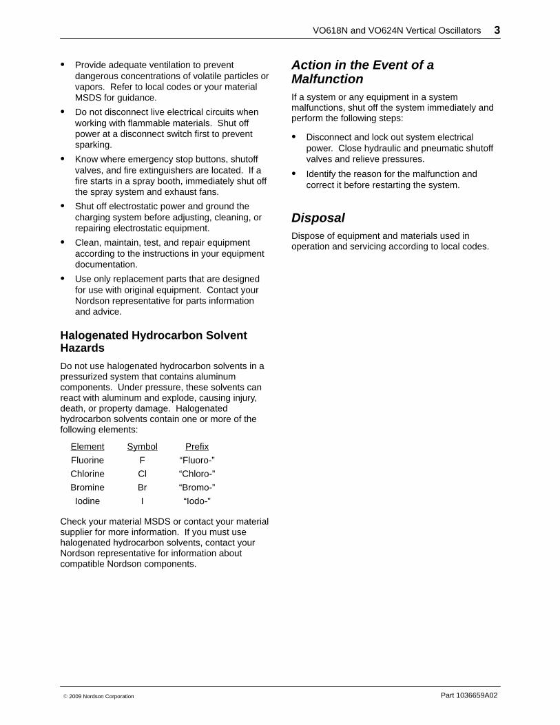
Description Vertical oscillators are designed to move sprayguns up and down in a smooth and repetitiouspattern for thorough coverage of parts beingcoated. Two versions of the vertical oscillator areavailable:
� VO618N: 6-18 inch stroke length
� VO624N: 6-24 inch stroke length
In addition, vertical oscillators are also availablewith explosion-proof motors for use in liquidfinishing systems. Speed control is accomplishedinternally through a variable sheave or externally bya VFD.
Table 1 Oscillator Speed Controls
Sheave Function
Variablespeedsheave
Stroke speed is manuallycontrolled using a knob on theback of the oscillator cabinet.
Motor sheaves separate to reducediameter and stroke speed andclose to increase diameter andstroke speed.
Fixedspeedsheave
Stroke speed is controlled by aVariable Frequency Drive.
Motor sheave diameter is fixed.
The osillators can support up to 12 automatic sprayguns, depending on the weight of the guns. Referto page 11 for Gun Loading charts.
The oscillator is typically mounted to either the flooror a horizontal in/out positioner, which moves theoscillator on- and off-line.
Figure 1 Oscillator
VO618N and VO624N Vertical Oscillators 5
Part 1036659A02� 2009 Nordson Corporation
Oscillator Components
4
5
6
8
9
11
3
1
2
10
7
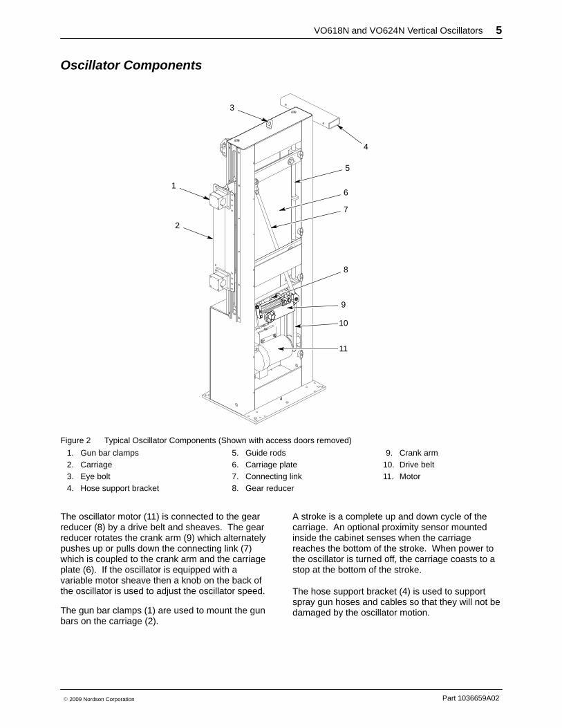
Figure 2 Typical Oscillator Components (Shown with access doors removed)
1. Gun bar clamps2. Carriage3. Eye bolt4. Hose support bracket
5. Guide rods6. Carriage plate7. Connecting link8. Gear reducer
9. Crank arm10. Drive belt11. Motor
The oscillator motor (11) is connected to the gearreducer (8) by a drive belt and sheaves. The gearreducer rotates the crank arm (9) which alternatelypushes up or pulls down the connecting link (7)which is coupled to the crank arm and the carriageplate (6). If the oscillator is equipped with avariable motor sheave then a knob on the back ofthe oscillator is used to adjust the oscillator speed.
The gun bar clamps (1) are used to mount the gunbars on the carriage (2).
A stroke is a complete up and down cycle of thecarriage. An optional proximity sensor mountedinside the cabinet senses when the carriagereaches the bottom of the stroke. When power tothe oscillator is turned off, the carriage coasts to astop at the bottom of the stroke.
The hose support bracket (4) is used to supportspray gun hoses and cables so that they will not bedamaged by the oscillator motion.
VO618N and VO624N Vertical Oscillators6
Part 1036659A02 � 2009 Nordson Corporation
Installation
WARNING: Allow only qualified personnelto perform the following tasks. Follow thesafety instructions in this document and allother related documentation.
Reporting DamageInspect the oscillator before removing it from thepallet. Note any damage to the oscillator on the billof lading and report it to the carrier.
If concealed damage is discovered while you areinstalling the oscillator, stop immediately and notifythe carrier. Do not proceed until a carrierrepresentative arrives to inspect the damage.
After removing the oscillator, make sure that allitems listed on the packing slip are present. If anitem listed on the packing slip is missing, note themissing item on the bill of lading and report theshortage to the carrier.
File a formal claim immediately with the carrier forany loss or damage. A notation on the bill of ladingdoes not constitute notification of a claim. Thefollowing documents should be supplied to thecarrier to support your claim:
� original freight bill
� original bill of lading
� copy of invoice or other evidence of value
� correspondence or photographs related to theclaim
� concealed damage forms when necessary
NOTE: Nordson Corporation is willing to assist youin filing your claim and collecting for loss ordamage. This willingness to assist you does notmake Nordson Corporation responsible forcollection of the claim or replacement of any loss.
Unloading and Connections
WARNING: Use approved and testedlifting equipment capable of lifting 635 kg(1400 lb) or more. Failure to observe thiswarning could result in property damage,injury, or death.
See Figure 2.
1. Remove the screws securing the shippingbrackets to the pallet.
2. Attach lifting equipment to the eye bolt (3) andcarefully lift the oscillator off the pallet.
3. Stand the oscillator upright on the floor or anin/out positioner. Secure the oscillator to thefloor or in/out positioner.
4. Open the access doors and make sure noforeign material is present inside the oscillatorcabinet that would jam or prevent smoothoperation of the oscillator.
5. Check the gear reducer for proper oil level.Refer to Maintenance for the recommended oil.Make sure that the breather plug is installed inthe gear reducer. If there is a pipe pluginstalled, replace it with the breather plug.
CAUTION: The sensor cable must bewired through an intrinsically safe barrierfor Class 1, Division 1 environment.
6. Connect the 15-ft proximity sensor cable (ifused) to the system controls, as required by theapplication.
7. Check the voltage of the oscillator motor (8).Make sure that the supply voltage matches thevoltage of the motor.
WARNING: Connect the oscillator powercable to a disconnect or other device thatwill allow power to be locked out forservice. Failure to observe this warningmay result in personal injury or death.
VO618N and VO624N Vertical Oscillators 7
Part 1036659A02� 2009 Nordson Corporation
8. Connect a customer-supplied power cablebetween the motor junction box and a powersupply:
Wire Color Wire Function
Red T1
Black T2
Blue T3
Orange GND
9. Ground the oscillator, using the providedgrounding lug, to a true earth ground. Test theground and make sure it does not exceed localcode requirements.
10. Mount the spray guns on the oscillator usingappropriate gun mounting bars. Bundle the guncables and hoses and hang them from hosesupport bracket (4), if used.
11. Close and secure the access doors.
Operation WARNING: Allow only qualified personnel to perform the following tasks. Follow the safetyinstructions in this document and all other related documentation.
WARNING: Before starting the oscillator, make sure nothing interferes with the gun bars or guns.Warn any personnel in the area to keep clear. Failure to observe this warning could result inproperty damage, injury, or death.
WARNING: Never open the access doors while the oscillator is operating. Failure to observe thiswarning may result in equipment damage or personal injury.
Stroke Adjustment
CAUTION: If stroke length is changed, carriage speed may have to be adjusted proportionally toprevent an over-speed condition. Maximum allowable carriage speed is 100 fpm.
CAUTION: Contact your Nordson representative before making adjustments to the connecting link.Failure to observe this caution may result in equipment damage.
Slide-Type Crank Arm
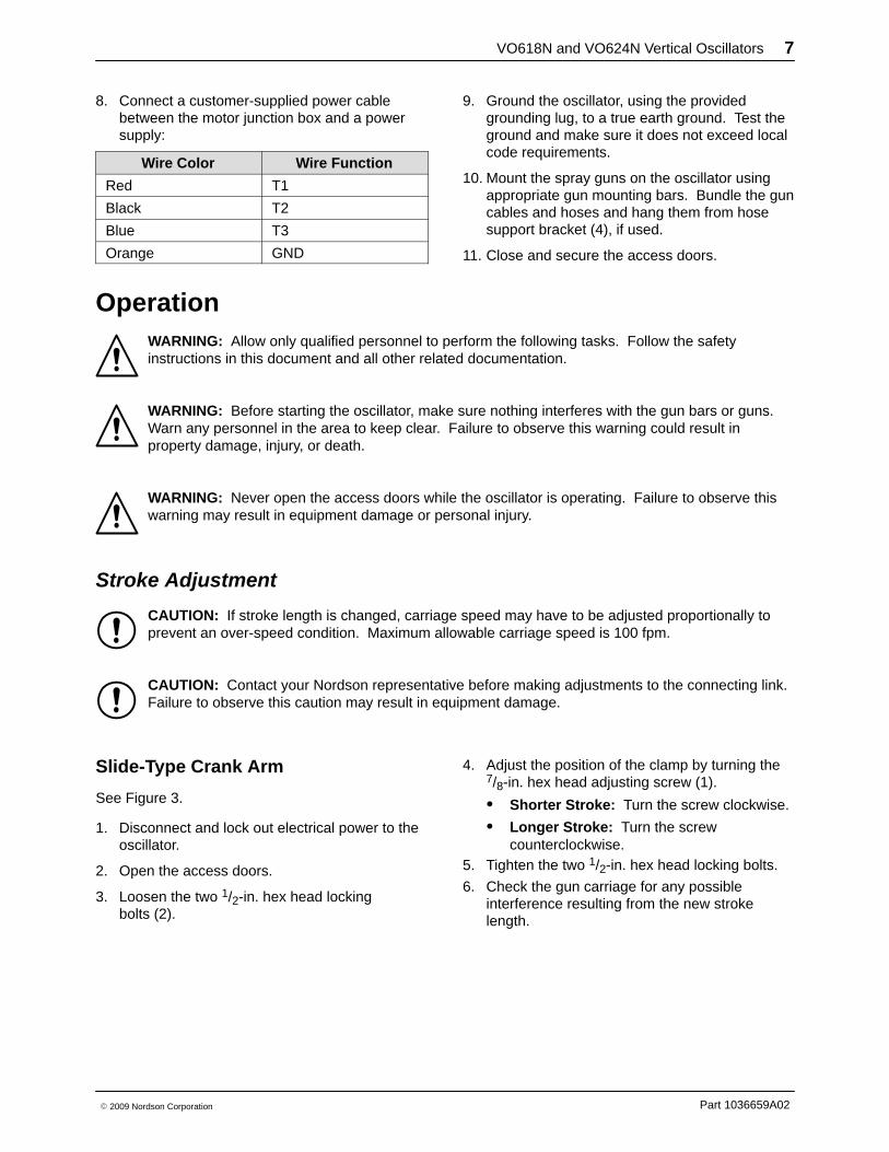
See Figure 3.
1. Disconnect and lock out electrical power to theoscillator.
2. Open the access doors.
3. Loosen the two 1/2-in. hex head lockingbolts (2).
4. Adjust the position of the clamp by turning the7/8-in. hex head adjusting screw (1).
� Shorter Stroke: Turn the screw clockwise.
� Longer Stroke: Turn the screwcounterclockwise.
5. Tighten the two 1/2-in. hex head locking bolts.
6. Check the gun carriage for any possibleinterference resulting from the new strokelength.
VO618N and VO624N Vertical Oscillators8
Part 1036659A02 � 2009 Nordson Corporation
7. Remove all tools from the oscillator, close theaccess doors, and reconnect the power to theoscillator.
8. Test the new stroke length to make sure thatparts going through the booth will be coveredby the gun stroke.
9. Adjust the oscillator speed if necessary toaccommodate the new stroke length. Refer toSpeed Adjustment for instructions.
1
2
3
Figure 3 Stroke Adjustment - Slide-Type Crank Arm
1. Adjusting screw2. Locking bolts
3. Adjusting clamp
Solid Crank Arm
See Figure 4.
1. Disconnect and lock out electrical power to theoscillator.
2. Open the access doors.
3. Take the weight off the connecting link bysupporting the carriage from outside thecabinet.
WARNING: Extreme care must be takento ensure that the carriage is supportedsecurely so that the carriage cannot movewhen the connecting link is disconnected.Failure to observe this warning could resultin personal injury.
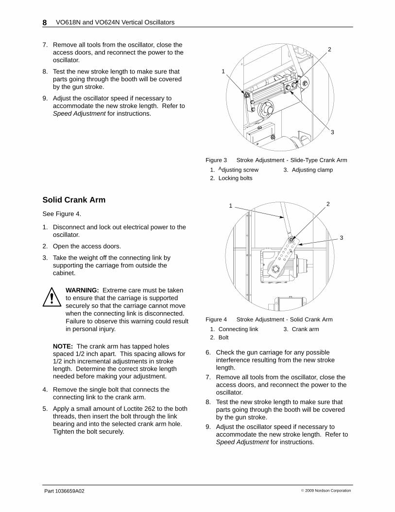
NOTE: The crank arm has tapped holesspaced 1/2 inch apart. This spacing allows for1/2 inch incremental adjustments in strokelength. Determine the correct stroke lengthneeded before making your adjustment.
4. Remove the single bolt that connects theconnecting link to the crank arm.
5. Apply a small amount of Loctite 262 to the boththreads, then insert the bolt through the linkbearing and into the selected crank arm hole.Tighten the bolt securely.
1 2
3
Figure 4 Stroke Adjustment - Solid Crank Arm
1. Connecting link2. Bolt
3. Crank arm
6. Check the gun carriage for any possibleinterference resulting from the new strokelength.
7. Remove all tools from the oscillator, close theaccess doors, and reconnect the power to theoscillator.
8. Test the new stroke length to make sure thatparts going through the booth will be coveredby the gun stroke.
9. Adjust the oscillator speed if necessary toaccommodate the new stroke length. Refer toSpeed Adjustment for instructions.
VO618N and VO624N Vertical Oscillators 9
Part 1036659A02� 2009 Nordson Corporation
Speed Adjustment The oscillator must be operating while you adjust the speed. Measure the speed by counting the strokecycles. One stroke cycle equals both the up and down motion.
CAUTION: The maximum allowable carriage speed is the lower of 100 feet per minute or 44 cyclesper minute. Refer to the Carrige Speed-Stroke charts on the following pages.
Fixed-Sheave Oscillator
An oscillator with a fixed motor sheave requires acustomer-supplied Variable Frequency Drive tocontrol the speed of the oscillator.
Since the reducer is capable of overhauling, theVFD must be carefully selected to prevent damageto the oscillator.
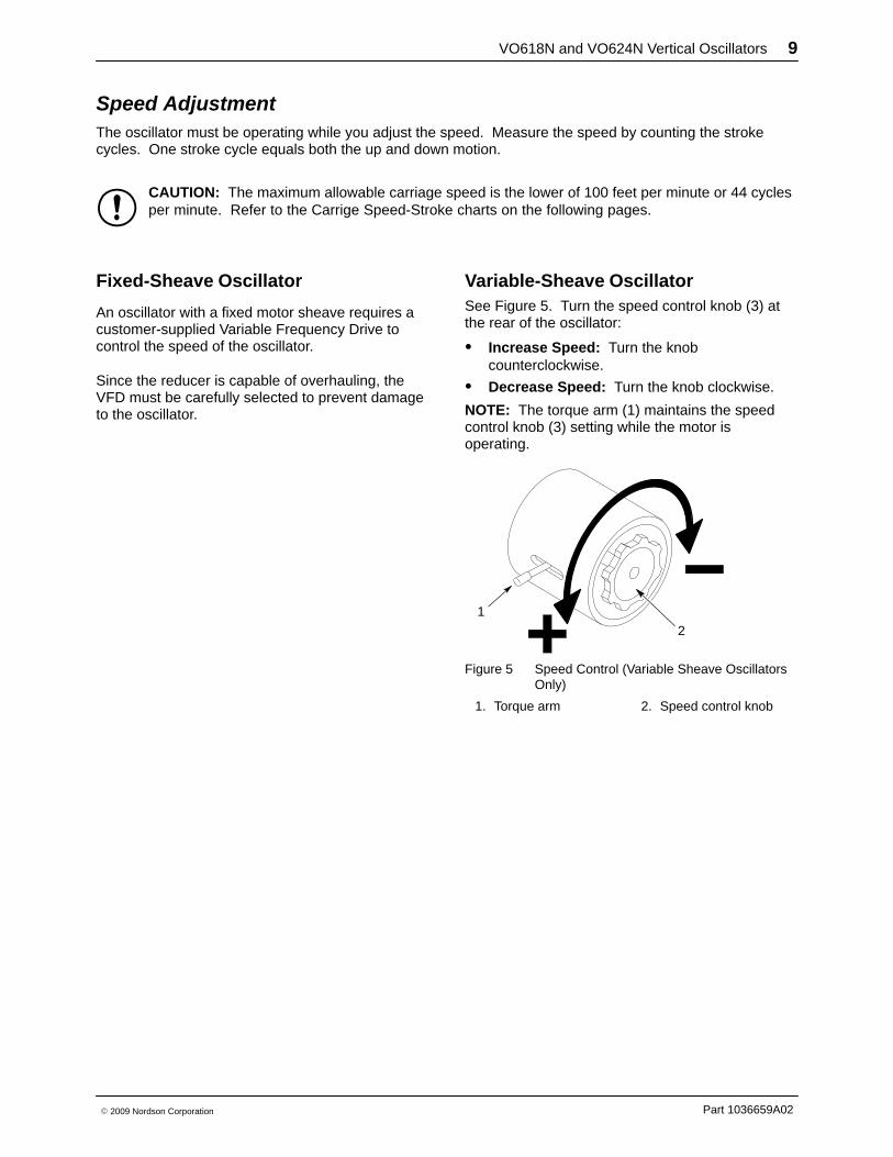
Variable-Sheave Oscillator See Figure 5. Turn the speed control knob (3) atthe rear of the oscillator:
� Increase Speed: Turn the knobcounterclockwise.
� Decrease Speed: Turn the knob clockwise.
NOTE: The torque arm (1) maintains the speedcontrol knob (3) setting while the motor isoperating.
2
1
Figure 5 Speed Control (Variable Sheave OscillatorsOnly)
1. Torque arm 2. Speed control knob

VO618N and VO624N Vertical Oscillators10
Part 1036659A02 � 2009 Nordson Corporation
Carriage Speed-Stroke Charts
110
100
90
80
70
60
50
40
30
20
10
100
27
STROKE (in)
10 12 14 16 18860
Carriage Speed - Stroke ChartVO618 Oscillator
(60 Hz Motor)
CA
RR
IAG
E S
PE
ED
(F
PM
)
Figure 6 Carriage Speed/Stroke Chart for VO618 Oscillator
Carriage Speed - Stroke ChartVO624 Oscillator
(60 Hz Motor)
Figure 7 Carriage Speed/Stroke Chart for VO624 Oscillator
VO618N and VO624N Vertical Oscillators 11
Part 1036659A02� 2009 Nordson Corporation
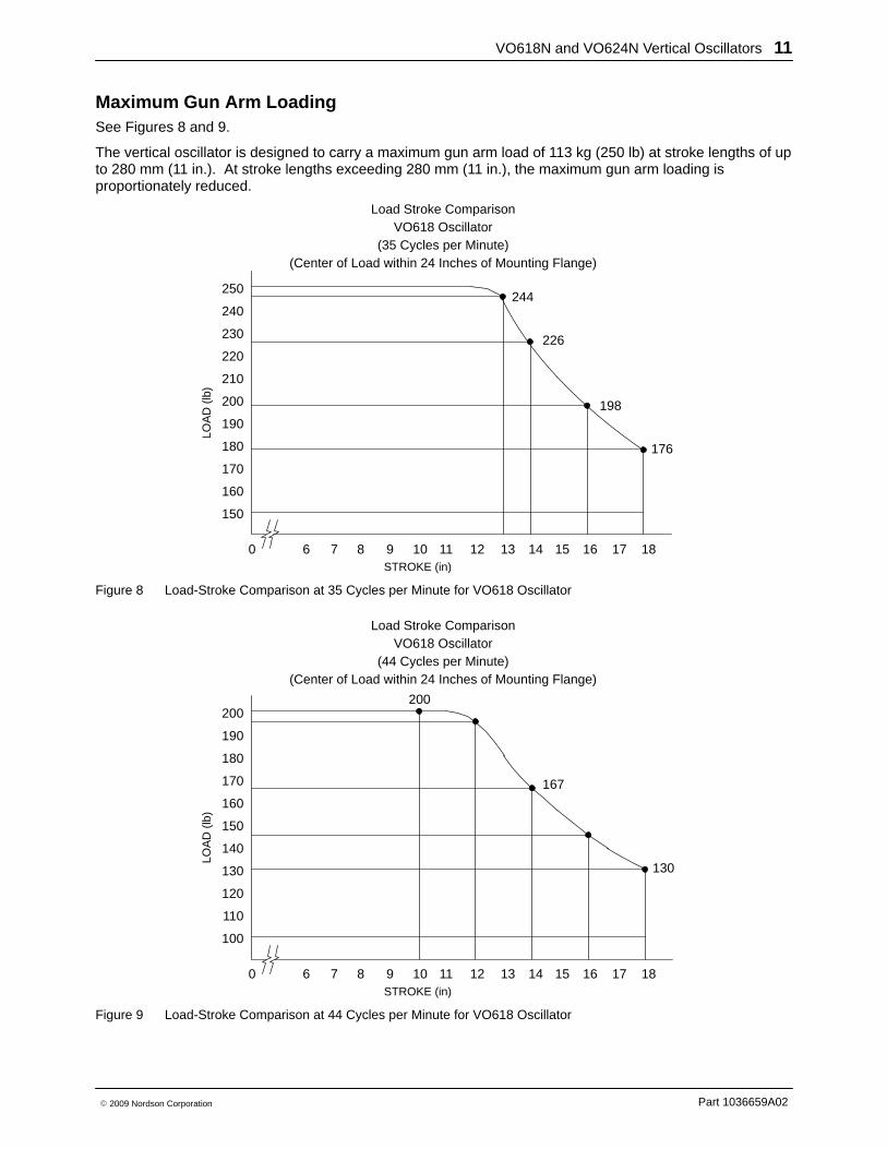
Maximum Gun Arm Loading See Figures 8 and 9.
The vertical oscillator is designed to carry a maximum gun arm load of 113 kg (250 lb) at stroke lengths of upto 280 mm (11 in.). At stroke lengths exceeding 280 mm (11 in.), the maximum gun arm loading isproportionately reduced.
250
240
230
220
210
200
190
180
170
160
150
244
226
176
LOA
D (
lb)
STROKE (in)
10 11 12 13 14 15 16 17 1898760
Load Stroke ComparisonVO618 Oscillator
(35 Cycles per Minute)(Center of Load within 24 Inches of Mounting Flange)
198
Figure 8 Load-Stroke Comparison at 35 Cycles per Minute for VO618 Oscillator
200
190
180
170
160
150
140
130
120
110
100
200
167
130
LOA
D (
lb)
STROKE (in)
10 11 12 13 14 15 16 17 1898760
Load Stroke ComparisonVO618 Oscillator
(44 Cycles per Minute)(Center of Load within 24 Inches of Mounting Flange)
Figure 9 Load-Stroke Comparison at 44 Cycles per Minute for VO618 Oscillator
VO618N and VO624N Vertical Oscillators12
Part 1036659A02 � 2009 Nordson Corporation
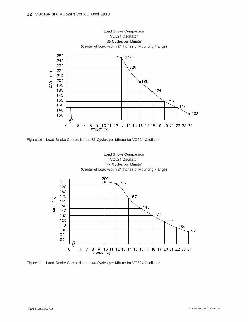
Load Stroke ComparisonVO624 Oscillator
(35 Cycles per Minute)(Center of Load within 24 Inches of Mounting Flange)
Figure 10 Load-Stroke Comparison at 35 Cycles per Minute for VO624 Oscillator
Load Stroke ComparisonVO624 Oscillator
(44 Cycles per Minute)(Center of Load within 24 Inches of Mounting Flange)
Figure 11 Load-Stroke Comparison at 44 Cycles per Minute for VO624 Oscillator

VO618N and VO624N Vertical Oscillators 13
Part 1036659A02� 2009 Nordson Corporation
Maintenance WARNING: Allow only qualified personnel to perform the following tasks. Follow the safetyinstructions in this document and all other related documentation.
WARNING: Disconnect equipment from the line voltage before servicing the equipment. Failure toobserve this warning may result in a severe shock.
Perform maintenance and lubrication procedures according to the recommended intervals. Refer to Repairfor disassembly and rebuilding instructions.
Break-In Period Refer to Table 2 and Figure 12 for maintenance procedures for the first 500 hours or five weeks (whichevercomes first) of oscillator operation.
Table 2 Break-In Period Maintenance Schedule
Item Description Time Period Procedure
4 Gear Reducer
Daily
Check the operating temperature.
Normal Operating Temperature:Less than 80 �C (175 �F)
NOTE: During the initial break-in period,temperatures may rise above 80 �C (175 �F). Ifthis temperature is exceeded for more than100 hours, contact your Nordson representative.
First 500 hours/five weeks inoperation
Change the original oil.
NOTE: The gear reducer requires 0.838 liter(0.885 quart) of synthetic worm gear oil (AGMA 7 or 8).
7 MotorFirst 500 hours/five weeks inoperation
Check the motor current draw and compare thereading to the value on the motor nameplate.

VO618N and VO624N Vertical Oscillators14
Part 1036659A02 � 2009 Nordson Corporation
Normal Operation Maintenance Refer to Table 3 and Figure 12.
NOTE: Follow these procedures after the initialbreak-in period (which is 500 hours or five weeks,whichever comes first).
Table 3 Normal Operation Maintenance Schedule
Item Description Frequency Procedure
— General Cleaning Daily
Clean the interior of the oscillator and lubricateall moving parts.
Check for overspray build-up and slack in thedrive belt. Clean and adjust the drive belt asnecessary.
NOTE: If the oscillator is located in an inherentlydirty environment or if the overspray build up isexcessive, consider installing a pressurizing unit.Oscillators with built-in pressurizing units areavailable. Contact your Nordson representativefor more information.
4 Gear Reducer
Daily
Check the operating temperature.
Normal Operating Temperature:Less than 80 �C (175 �F)
NOTE: During the initial break-in period,temperatures may rise above 80 �C (175 �F). Ifthis temperature is exceeded for more than100 hours, contact your Nordson representative.
Weekly Check for oil leaks and correct as needed.
10000 hours/twoyears
Change the oil.
NOTE: The gear reducer requires 0.838 liter(0.885 quart) of synthetic worm gear oil(AGMA 7 or 8).
7 Motor WeeklyClean the grille over the fan on the rear of themotor. Make sure that it is clear of any dirtbuildup.
Gun CarriageWeekly
Wipe overspray off the guide rods and lubricatethe linear bearings with a high-quality,lithium-based, multipurpose grease.
1, 3Gun CarriageGuide Rods andBearings
Monthly
Inspect the guide rods for excessive or abnormalwear. Evidence of deep grooves indicate thatthe linear bearings or guide rods are out ofalignment.
2, 5Connecting Linkand Rod EndBearing
WeeklyLubricate with a high-quality, lithium-based,multipurpose grease.
8 Crank Arm Monthly Check the tightness of all screws and nuts.Tighten as required.
6 Drive Belt Monthly Inspect for cracks and fraying. Replace the drivebelt as necessary.
VO618N and VO624N Vertical Oscillators 15
Part 1036659A02� 2009 Nordson Corporation
1
3
1
4
5
78
2
6
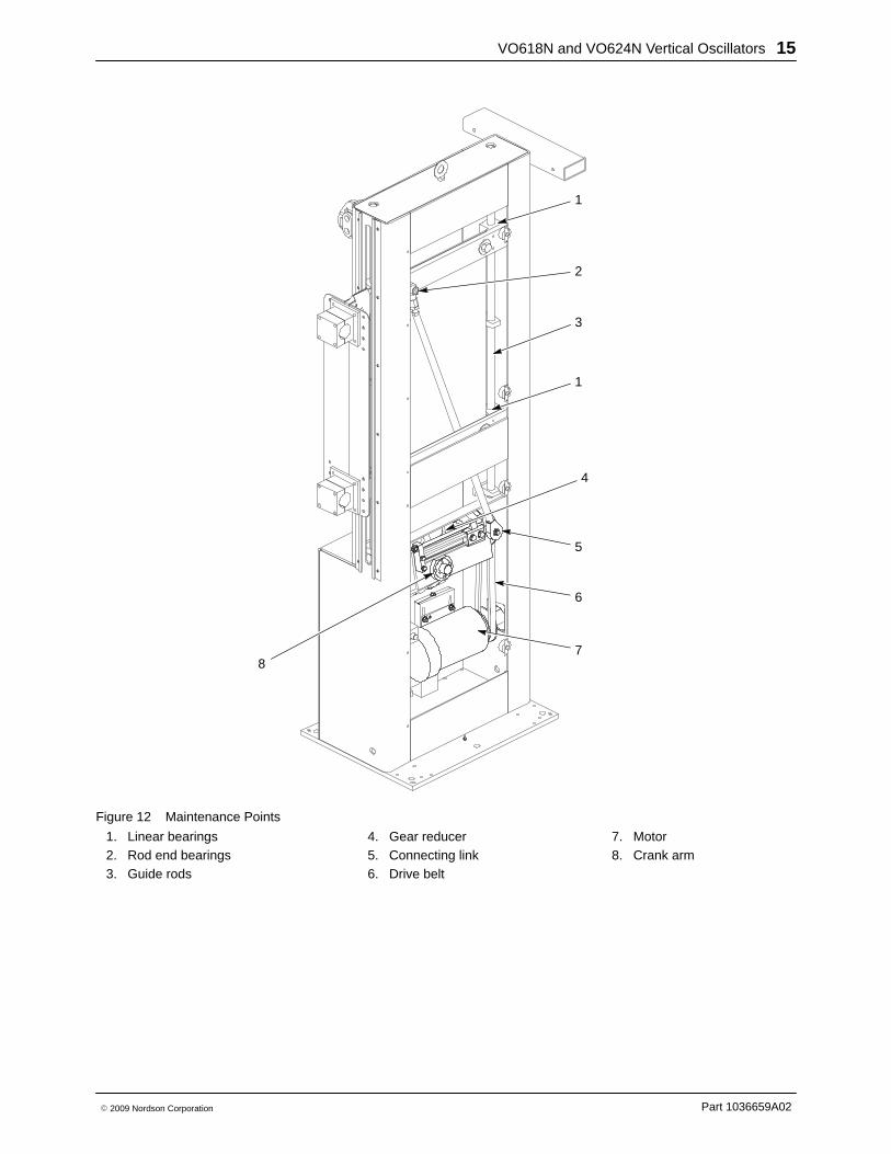
Figure 12 Maintenance Points
1. Linear bearings2. Rod end bearings3. Guide rods
4. Gear reducer5. Connecting link6. Drive belt
7. Motor8. Crank arm
VO618N and VO624N Vertical Oscillators16
Part 1036659A02 � 2009 Nordson Corporation
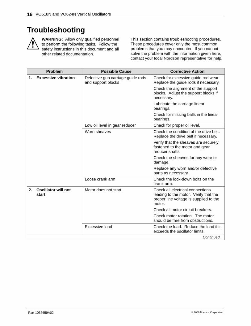
Troubleshooting WARNING: Allow only qualified personnelto perform the following tasks. Follow thesafety instructions in this document and allother related documentation.
This section contains troubleshooting procedures.These procedures cover only the most commonproblems that you may encounter. If you cannotsolve the problem with the information given here,contact your local Nordson representative for help.
Problem Possible Cause Corrective Action
1. Excessive vibration Defective gun carriage guide rodsand support blocks
Check for excessive guide rod wear.Replace the guide rods if necessary.
Check the alignment of the supportblocks. Adjust the support blocks ifnecessary.
Lubricate the carriage linearbearings.
Check for missing balls in the linearbearings.
Low oil level in gear reducer Check for proper oil level.
Worn sheaves Check the condition of the drive belt.Replace the drive belt if necessary.
Verify that the sheaves are securelyfastened to the motor and gearreducer shafts.
Check the sheaves for any wear ordamage.
Replace any worn and/or defectiveparts as necessary.
Loose crank arm Check the lock-down bolts on thecrank arm.
2. Oscillator will notstart
Motor does not start Check all electrical connectionsleading to the motor. Verify that theproper line voltage is supplied to themotor.
Check all motor circuit breakers.
Check motor rotation. The motorshould be free from obstructions.
Excessive load Check the load. Reduce the load if itexceeds the oscillator limits.
Continued...
VO618N and VO624N Vertical Oscillators 17
Part 1036659A02� 2009 Nordson Corporation
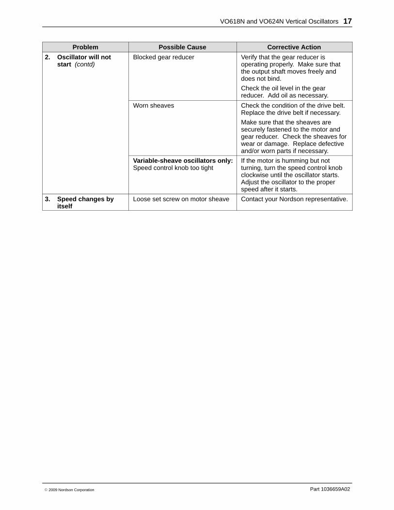
Problem Possible Cause Corrective Action
2. Oscillator will notstart (contd)
Blocked gear reducer Verify that the gear reducer isoperating properly. Make sure thatthe output shaft moves freely anddoes not bind.
Check the oil level in the gearreducer. Add oil as necessary.
Worn sheaves Check the condition of the drive belt.Replace the drive belt if necessary.
Make sure that the sheaves aresecurely fastened to the motor andgear reducer. Check the sheaves forwear or damage. Replace defectiveand/or worn parts if necessary.
Variable-sheave oscillators only:Speed control knob too tight
If the motor is humming but notturning, turn the speed control knobclockwise until the oscillator starts.Adjust the oscillator to the properspeed after it starts.
3. Speed changes byitself
Loose set screw on motor sheave Contact your Nordson representative.
VO618N and VO624N Vertical Oscillators18
Part 1036659A02 � 2009 Nordson Corporation
Repair
WARNING: Allow only qualified personnelto perform the following tasks. Follow thesafety instructions in this document and allother related documentation.
WARNING: Disconnect and lock outpower to the oscillator before servicing.Failure to observe this warning may resultin personal injury.
Drive Belt Replacement
WARNING: Be sure that the gun carriageis securely supported before proceding.Failure to observe this warning may causethe carriage to slip, causing propertydamage, personal injury, or death.
Removing the Drive Belt
NOTE: Use the appropriate procedure based onthe type of oscillator you have (variable-speed orfixed-speed sheave).
Variable-Sheave Oscillator
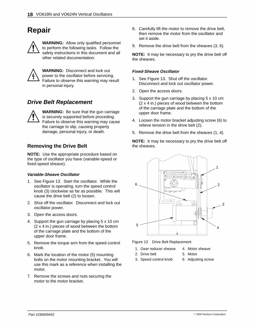
1. See Figure 13. Start the oscillator. While theoscillator is operating, turn the speed controlknob (3) clockwise as far as possible. This willcause the drive belt (2) to loosen.
2. Shut off the oscillator. Disconnect and lock outoscillator power.
3. Open the access doors.
4. Support the gun carriage by placing 5 x 10 cm(2 x 4 in.) pieces of wood between the bottomof the carriage plate and the bottom of theupper door frame.
5. Remove the torque arm from the speed controlknob.
6. Mark the location of the motor (5) mountingbolts on the motor mounting bracket. You willuse this mark as a reference when installing themotor.
7. Remove the screws and nuts securing themotor to the motor bracket.
8. Carefully lift the motor to remove the drive belt,then remove the motor from the oscillator andset it aside.
9. Remove the drive belt from the sheaves (3, 6).
NOTE: It may be necessary to pry the drive belt offthe sheaves.
Fixed-Sheave Oscillator
1. See Figure 13. Shut off the oscillator.Disconnect and lock out oscillator power.
2. Open the access doors.
3. Support the gun carriage by placing 5 x 10 cm(2 x 4 in.) pieces of wood between the bottomof the carriage plate and the bottom of theupper door frame.
4. Loosen the motor bracket adjusting screw (6) torelieve tension in the drive belt (2).
5. Remove the drive belt from the sheaves (1, 4).
NOTE: It may be necessary to pry the drive belt offthe sheaves.
5
1
2
3
4
6
Figure 13 Drive Belt Replacement
1. Gear reducer sheave2. Drive belt3. Speed control knob
4. Motor sheave5. Motor6. Adjusting screw
VO618N and VO624N Vertical Oscillators 19
Part 1036659A02� 2009 Nordson Corporation
Installing the Drive Belt
Variable-Sheave Oscillator
1. See Figure 13. Install a new drive belt (2) onthe gear reducer sheave (1).
2. Carefully lift the motor (5) into place and slidethe drive belt onto the motor sheave (4).
NOTE: Make sure that the faces of the sheavesare parallel before tightening the motor mountingbolts.
3. Align the motor in its previous location on themotor bracket. Secure the motor using thescrews and nuts.
4. Install the torque arm onto the speed controlknob (3).
5. Remove the wood block supporting the carriageplate.
6. Connect power and start the oscillator.
7. Turn the speed control knob counterclockwiseto tighten the drive belt.
8. Check the drive belt while the oscillator isoperating.
9. Adjust the oscillator speed as necessary.
Fixed-Sheave Oscillator
1. See Figure 13. Install the new drive belt (4)onto the gear reducer and motor sheaves(1, 4).
2. Position the motor so that the belt will deflect nomore than 1/4 in. Tighten the motor bracketadjusting screw (6).
3. Remove the wood block supporting the carriageplate.
4. Connect power and start the oscillator.
5. Check the drive belt while the oscillator isoperating.
6. Adjust the oscillator speed as necessary.
Gun Carriage Linear Bearing andGuide Rod Replacement
CAUTION: Replacement and adjustmentsof the gun carriage bearings and guiderods is a procedure requiring greatprecision. It is best accomplished by atrained and authorized Nordson technician.
See Figure 14.
1. Turn off and lock out power to the oscillator.
2. Open the access doors.
WARNING: Be sure that the gun carriageis securely supported before proceding.Failure to observe this warning may causethe carriage to slip, causing propertydamage, personal injury, or death.
3. Support the carriage plate (4) from the outsideof the cabinet to take the weight off the linearbearing blocks (1).
CAUTION: Remove the guide rodassemblies one at a time. Do not removeboth assemblies simultanously. Removingboth guide rod assemblies will leavenothing to support the carriage plate frominside the oscillator.
4. Remove one guide rod assembly using thefollowing procedure:
a. Remove the bolts and nuts securing bothlinear bearing blocks to the carriage plate.Note the locations of any shims or spacerblocks, and save them for reuse.
NOTE: There are three shaft support blocks oneach guide rod.
b. Remove the bolts securing the shaft supportblocks (3) to the oscillator cabinet. Note thelocations of any shims and save them forreuse.
c. Remove the guide rod (2) with the threeshaft support blocks and two linear bearingsattached.
d. Loosen the shaft support blocks and slidethem off the guide rod. Slide the linearbearings off the guide rod.
VO618N and VO624N Vertical Oscillators20
Part 1036659A02 � 2009 Nordson Corporation
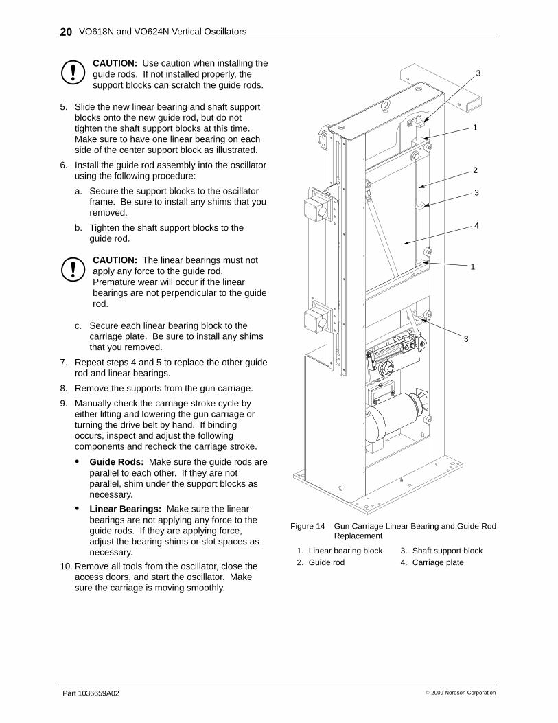
CAUTION: Use caution when installing theguide rods. If not installed properly, thesupport blocks can scratch the guide rods.
5. Slide the new linear bearing and shaft supportblocks onto the new guide rod, but do nottighten the shaft support blocks at this time.Make sure to have one linear bearing on eachside of the center support block as illustrated.
6. Install the guide rod assembly into the oscillatorusing the following procedure:
a. Secure the support blocks to the oscillatorframe. Be sure to install any shims that youremoved.
b. Tighten the shaft support blocks to theguide rod.
CAUTION: The linear bearings must notapply any force to the guide rod.Premature wear will occur if the linearbearings are not perpendicular to the guiderod.
c. Secure each linear bearing block to thecarriage plate. Be sure to install any shimsthat you removed.
7. Repeat steps 4 and 5 to replace the other guiderod and linear bearings.
8. Remove the supports from the gun carriage.
9. Manually check the carriage stroke cycle byeither lifting and lowering the gun carriage orturning the drive belt by hand. If bindingoccurs, inspect and adjust the followingcomponents and recheck the carriage stroke.
� Guide Rods: Make sure the guide rods areparallel to each other. If they are notparallel, shim under the support blocks asnecessary.
� Linear Bearings: Make sure the linearbearings are not applying any force to theguide rods. If they are applying force,adjust the bearing shims or slot spaces asnecessary.
10. Remove all tools from the oscillator, close theaccess doors, and start the oscillator. Makesure the carriage is moving smoothly.
1
3
4
1
2
3
3
Figure 14 Gun Carriage Linear Bearing and Guide RodReplacement
1. Linear bearing block2. Guide rod
3. Shaft support block4. Carriage plate
VO618N and VO624N Vertical Oscillators 21
Part 1036659A02� 2009 Nordson Corporation
Gear Reducer Replacement
WARNING: Do not make adjustments tothe connecting link. Failure to observe thiswarning may cause the carriage plate tocrash into the guide rod support blocks,causing property damage, personal injury,or death.
Removing the Gear Reducer
See Figure 15.
1. Stop the oscillator at the highest point of thestroke to provide the maximum amount of roomto work.
2. Disconnect and lock out power to the oscillator.
WARNING: Be sure that the gun carriageis securely supported before proceding.Failure to observe this warning may causethe carriage to slip, causing propertydamage, personal injury, or death.
3. Place a support 2.5 cm (1 in.) below thecarriage and lower the carriage onto thesupport. The 2.5-cm (1-in.) space facilitatesassembly of the carriage drive components.
NOTE: The carriage can be supported by securingtwo-piece 2.5-cm (1-in.) bore clamp collars on thecarriage guide rods (2) below the bearing blocks oneach guide rod assembly.
4. Remove the connecting link (3) from the crankarm assembly (9).
NOTE: Measure the distance from the gearreducer housing to the back of the crank arm. Youwill need this measurement when you install thecrank arm onto the new gear reducer.
5. Remove the crank arm assembly by followingone of these procedures:
Slide-Type Crank Arm Removal
a. Remove the two set screws in the crankarm hub (10). Note that there is one tappedhole in the hub without a set screw.
b. Install one of the set screws that you justremoved into the empty tapped hole in thehub. Tighten the set screw to pry the crankarm off of the gear reducer shaft.
c. After installing the set screw as far aspossible, pry off the crank arm.
Solid Crank Arm Removal
a. To remove the crank arm hub, remove thesocket head screws holding the concentricclamping device. Note that there are 5threaded holes without screws installed.
b. Install 5 screws into the empty tappedholes. Alternately tighten the screws to prythe crank arm off the reducer shaft.
c. After installing the screws as far aspossible, pry off the crank arm.
6. Loosen the motor mounting bolts to slide themotor (7) up and remove the drive belt (5) fromthe gear reducer sheave (4).
NOTE: It may be necessary to pry the drive belt offof the sheave.
WARNING: The gear reducer weighsapproximately 23 kg (50 lb). Use cautionwhen removing the gear reducer from theoscillator.
7. Loosen the four bolts and remove the gearreducer.
NOTE: Measure the distance from the gearreducer housing to the rear of the gear reducersheave. You will need this measurement when youinstall the sheave onto the new gear reducer.
8. Remove the gear reducer sheave from the gearreducer.
Installing the Gear Reducer
See Figure 15.
1. Install the gear reducer sheave (4) onto thenew gear reducer (8). Position the sheave onthe shaft in the same location as it was on theold gear reducer.
NOTE: Make sure the gear reducer and motorsheaves (4, 6) are parallel before you tighten thegear reducer bolts. There should be approximately14 in. between the centers of the gear reducer andmotor shafts.
2. Install the new gear reducer (8) and secure itwith the four bolts.
3. Variable-speed sheave: Turn the control knobclockwise to the minium speed position.
VO618N and VO624N Vertical Oscillators22
Part 1036659A02 � 2009 Nordson Corporation
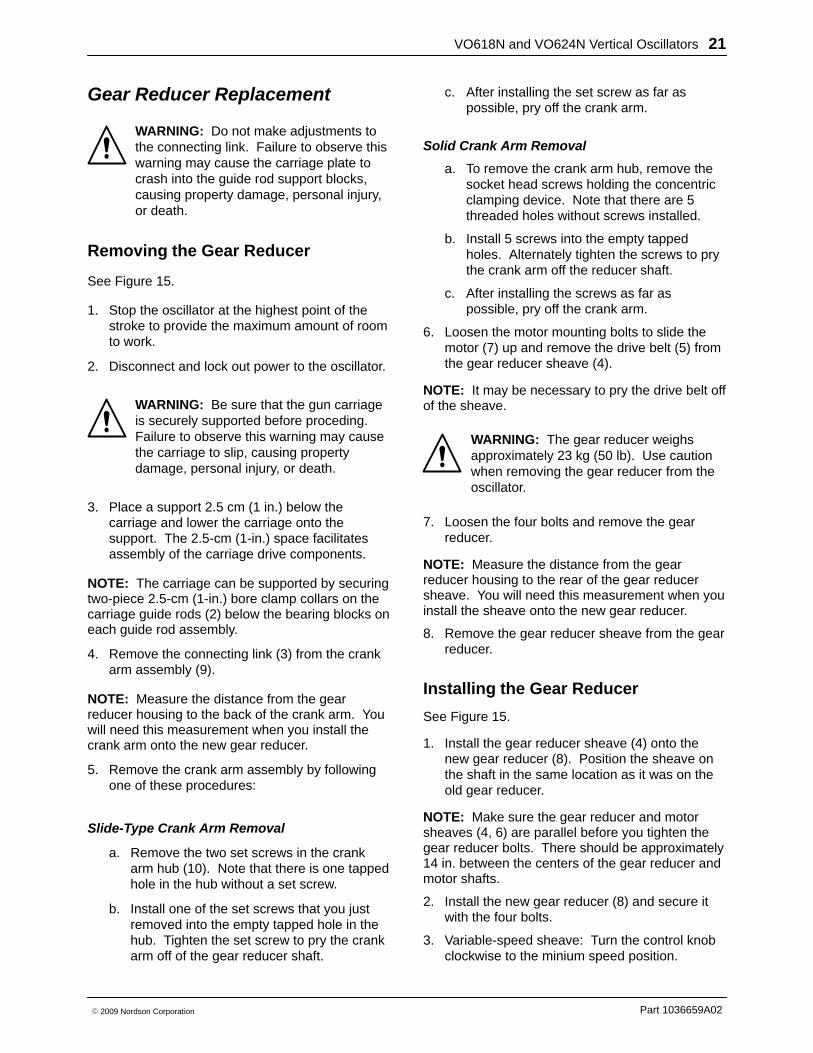
4. Install the drive belt on the sheaves andposition the motor if needed so that the pulleysare parallel. With fixed-speed sheaves the beltshould deflect no more than 6.3 mm (1/4 in.)Tighten the motor mounting bolts.
5. Install the crank arm assembly onto the gearreducer shaft. Position the crank arm on theshaft in the same location as it was on the oldgrear reducer.
6. Attach the connecting link to the crank armassembly. Make sure that the connecting link isparallel with the carriage plate assembly.
7. Remove the carriage plate supports.
NOTE: Make sure that the breather plug isinstalled in the new gear reducer. If there is a pipeplug installed, remove the breather plug from theold gear reducer and install it in place of the pipeplug.
8. Remove all tools from the oscillator.
9. Connect power to the oscillator.8
7
11
1
2
4
5
6
3
910
Figure 15 Gear Reducer and Connecting LinkReplacement
1. Linear bearings2. Guide rods3. Connecting link4. Gear reducer sheave5. Drive belt6. Motor sheave
7. Motor8. Gear reducer9. Crank arm assembly
10. Crank arm hub11. Gun carriage
Connecting Link Replacement
WARNING: Be sure that the gun carriageis securely supported before proceding.Failure to observe this warning may causethe carriage to slip, causing propertydamage, personal injury, or death.
1. Turn off and lock out power to the oscillator.
2. See Figure 15. Place a support 2.5 cm (1 in.)below the carriage and lower the carriage ontothe support. The 2.5-cm (1-in.) space facilitatesassembly of the carriage drive components.
NOTE: The carriage can be supported by securingtwo-piece 2.5-cm (1-in.) bore clamp collars on thecarriage guide rods (2) below the bearing blocks oneach guide rod assembly.
3. Unbolt the connecting link (3) from the guncarriage plate and the crank arm assembly (9).Note the placement of the spacers used toinstall the connecting link.
4. Install the new connecting link, remove the guncarriage supports, and manually check themotion of the carriage.
VO618N and VO624N Vertical Oscillators 23
Part 1036659A02� 2009 Nordson Corporation
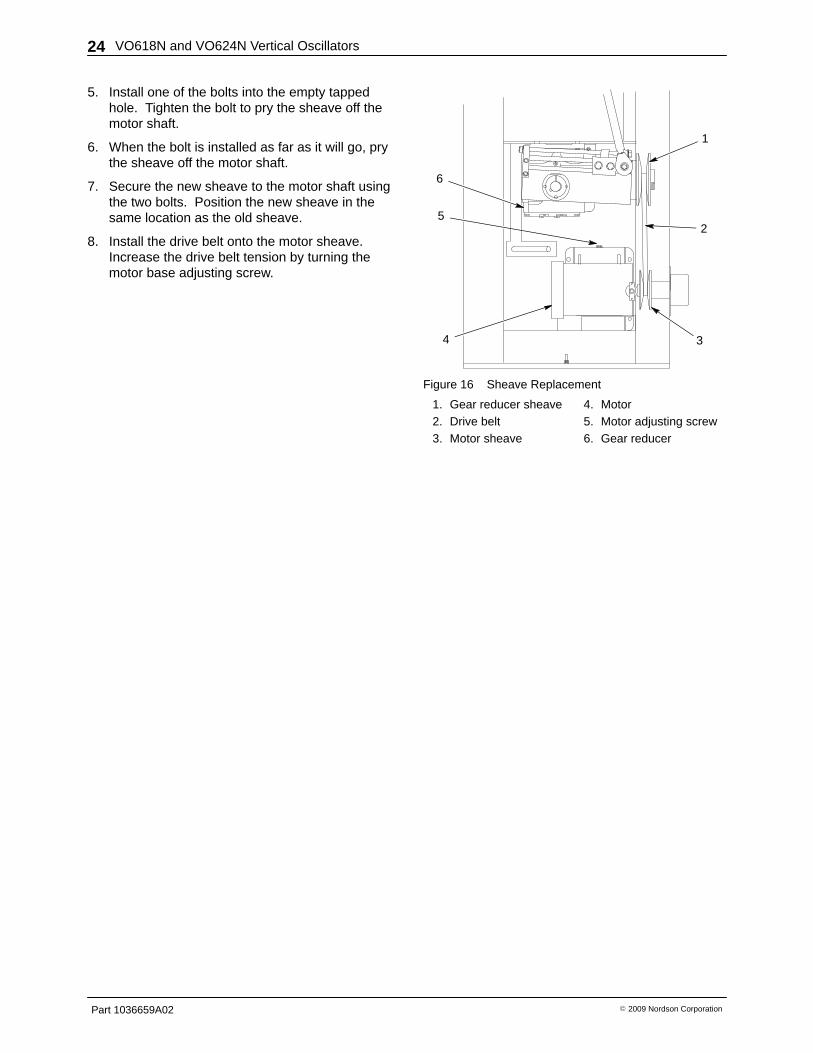
Sheave ReplacementUse the appropriate procedure based on the type of oscillator you have (variable sheave or fixed sheave).This repair procedure is different for each type of oscillator.
NOTE: Always replace both the gear reducer and motor sheaves at the same time.
Gear Reducer Sheave ReplacementVariable-Sheave Oscillator
1. See Figure 16. Remove the gear reducer (7)from the oscillator. Refer to Removing the GearReducer for instructions.
2. Measure the distance between the gearreducer housing and the sheave (1). The newsheave must be installed in the same locationas the existing sheave.
3. Remove the two bolts from the gear reducersheave hub. Note that there is one tapped holein the hub without a bolt.
4. Install one of the bolts into the empty tappedhole. Tighten the bolt to pry the sheave off thegear reducer shaft.
5. When the bolt is installed as far as it will go, prythe sheave off the gear reducer shaft.
6. Secure the new sheave to the gear reducershaft using the two bolts. Position the newsheave in the same location as the old sheave.
7. Install the gear reducer into the oscillator. Referto Installing the Gear Reducer for instructions.
Fixed-Sheave Oscillator
1. See Figure 16. Loosen the tension on the drivebelt (3) using the motor base adjustingscrew (6).
2. Measure the distance between the gearreducer (7) and the sheave (1). The newsheave must be installed in the same locationas the existing sheave.
3. Remove the two bolts from the gear reducersheave hub. Note that there is one tapped holein the hub without a bolt.
4. Install one of the bolts into the empty tappedhole. Tighten the bolt to pry the sheave off thegear reducer shaft.
5. When the bolt is installed as far as it will go, prythe sheave off the gear reducer shaft.
6. Secure the new sheave to the gear reducershaft using the two bolts. Position the newsheave in the same location as the old sheave.
7. Install the drive belt onto the gear reducersheave. Increase the drive belt tension byturning the motor base adjusting screw.
Motor Sheave Replacement
Variable-Sheave Oscillator
1. See Figure 16. Remove the motor (4) anddrive belt (2) from the oscillator. Refer toRemoving the Drive Belt for instructions.
2. Measure the distance between the motor andthe sheave (3). The new sheave must beinstalled in the same location as the existingsheave.
3. Loosen the motor sheave set screws and slidethe sheave off the motor shaft.
4. Secure the new sheave to the motor shaft usingthe set screws. Position the new sheave in thesame location as the old sheave.
5. Install the motor and drive belt into theoscillator. Refer to Installing the Drive Belt forinstructions.
Fixed-Sheave Oscillator
1. See Figure 16. Loosen the tension on the drivebelt (2) using the motor base adjustingscrew (5).
2. Remove the drive belt from the motor sheave.
3. Measure the distance between the motor (4)and the sheave (3). The new sheave must beinstalled in the same location as the existingsheave.
4. Remove the two bolts from the motor sheavehub. Note that there is one tapped hole in thetapered hub without a bolt.
VO618N and VO624N Vertical Oscillators24
Part 1036659A02 � 2009 Nordson Corporation
5. Install one of the bolts into the empty tappedhole. Tighten the bolt to pry the sheave off themotor shaft.
6. When the bolt is installed as far as it will go, prythe sheave off the motor shaft.
7. Secure the new sheave to the motor shaft usingthe two bolts. Position the new sheave in thesame location as the old sheave.
8. Install the drive belt onto the motor sheave.Increase the drive belt tension by turning themotor base adjusting screw.
4
1
3
52
6
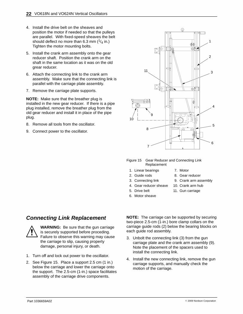
Figure 16 Sheave Replacement
1. Gear reducer sheave2. Drive belt3. Motor sheave
4. Motor5. Motor adjusting screw6. Gear reducer

VO618N and VO624N Vertical Oscillators 25
Part 1036659A02� 2009 Nordson Corporation
Parts To order parts, call the Nordson Industrial Coating Customer Service Center at (800) 433-9319 or contactyour local Nordson representative.
Parts listed in this manual are used on all oscillator models. For parts not listed in this manual, contact yourNordson representative or the Nordson Industrial Coating Customer Service Center.

VO618N and VO624N Vertical Oscillators26
Part 1036659A02 � 2009 Nordson Corporation
Variable-Sheave Oscillator Parts See Figure 17.
Item Part Description Quantity Note1 1017139 BEARING, rod end, number 1 1
2 1017142 BEARING, linear 4
3 1018007 SHAFT, class L, 1-in. dia x 51-in. long 2 B
3 1089682 SHAFT, class L, 1-in. dia x 60-in. long 2 C
4 1017140 BEARING, rod end, number 2 1
5 1017964 PULLEY, variable pitch, 5.75-in. OD 1
6 1018004 BELT, B section, 38-in. long 1
7 1018005 PULLEY, variable pitch, 5.0-in. OD 1
8 - - - - - - MOTOR 1 A
9 - - - - - - SENSOR, proximity, 2 wire, 5-25 Vdc, 18 mm 1 A
10 1017134 REDUCER, gear, helical worm, 66.44:1 1
NOTE A: Contact your Nordson representative about the availability of these parts.
B: Used on VO618 oscillator only.
C: Used on VO624 oscillator only.
2
3
4
7
10
1
6
8
9
5
Figure 17 Variable-Sheave Oscillator Parts
VO618N and VO624N Vertical Oscillators 27
Part 1036659A02� 2009 Nordson Corporation
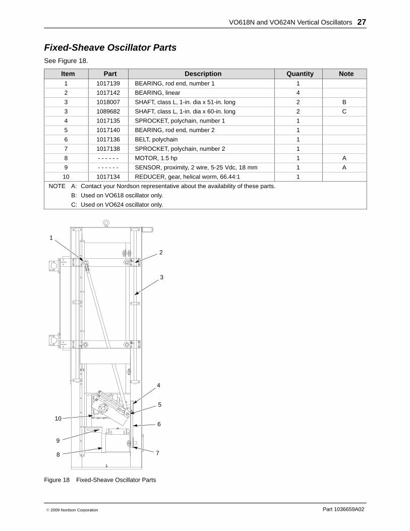
Fixed-Sheave Oscillator Parts See Figure 18.
Item Part Description Quantity Note1 1017139 BEARING, rod end, number 1 1
2 1017142 BEARING, linear 4
3 1018007 SHAFT, class L, 1-in. dia x 51-in. long 2 B
3 1089682 SHAFT, class L, 1-in. dia x 60-in. long 2 C
4 1017135 SPROCKET, polychain, number 1 1
5 1017140 BEARING, rod end, number 2 1
6 1017136 BELT, polychain 1
7 1017138 SPROCKET, polychain, number 2 1
8 - - - - - - MOTOR, 1.5 hp 1 A
9 - - - - - - SENSOR, proximity, 2 wire, 5-25 Vdc, 18 mm 1 A
10 1017134 REDUCER, gear, helical worm, 66.44:1 1
NOTE A: Contact your Nordson representative about the availability of these parts.
B: Used on VO618 oscillator only.
C: Used on VO624 oscillator only.
10
9
8
1
2
3
4
5
6
7
Figure 18 Fixed-Sheave Oscillator Parts
VO618N and VO624N Vertical Oscillators28
Part 1036659A02 � 2009 Nordson Corporation
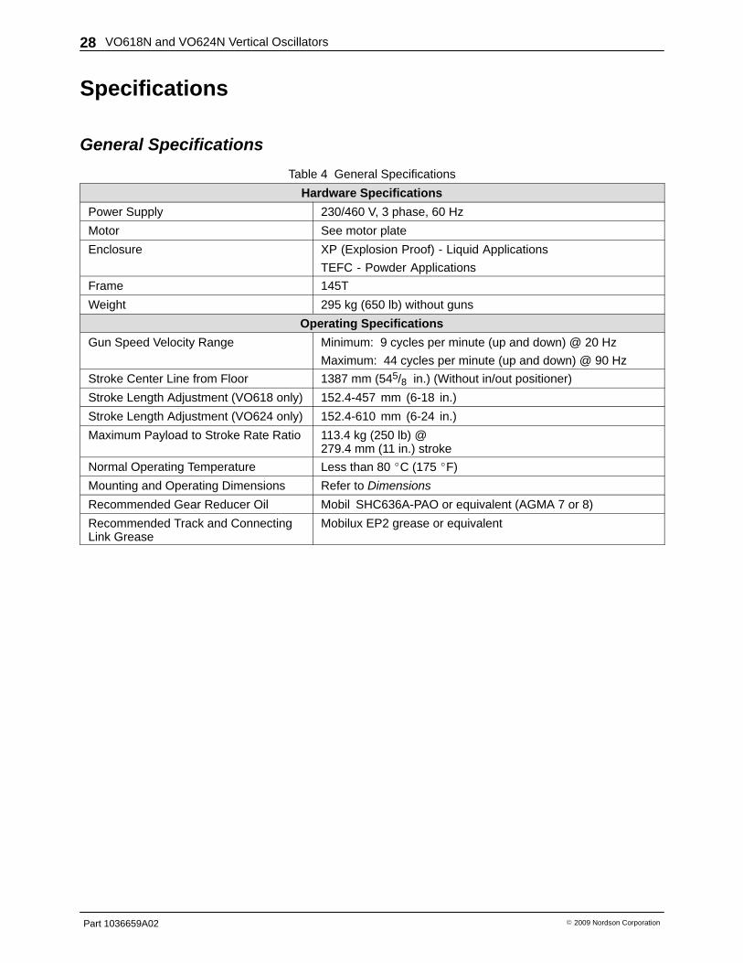
Specifications
General Specifications
Table 4 General Specifications
Hardware Specifications
Power Supply 230/460 V, 3 phase, 60 Hz
Motor See motor plate
Enclosure XP (Explosion Proof) - Liquid Applications
TEFC - Powder Applications
Frame 145T
Weight 295 kg (650 lb) without guns
Operating Specifications
Gun Speed Velocity Range Minimum: 9 cycles per minute (up and down) @ 20 Hz
Maximum: 44 cycles per minute (up and down) @ 90 Hz
Stroke Center Line from Floor 1387 mm (545/8 in.) (Without in/out positioner)
Stroke Length Adjustment (VO618 only) 152.4-457 mm (6-18 in.)
Stroke Length Adjustment (VO624 only) 152.4-610 mm (6-24 in.)
Maximum Payload to Stroke Rate Ratio 113.4 kg (250 lb) @ 279.4 mm (11 in.) stroke
Normal Operating Temperature Less than 80 �C (175 �F)
Mounting and Operating Dimensions Refer to Dimensions
Recommended Gear Reducer Oil Mobil SHC636A-PAO or equivalent (AGMA 7 or 8)
Recommended Track and ConnectingLink Grease
Mobilux EP2 grease or equivalent
VO618N and VO624N Vertical Oscillators 29
Part 1036659A02� 2009 Nordson Corporation
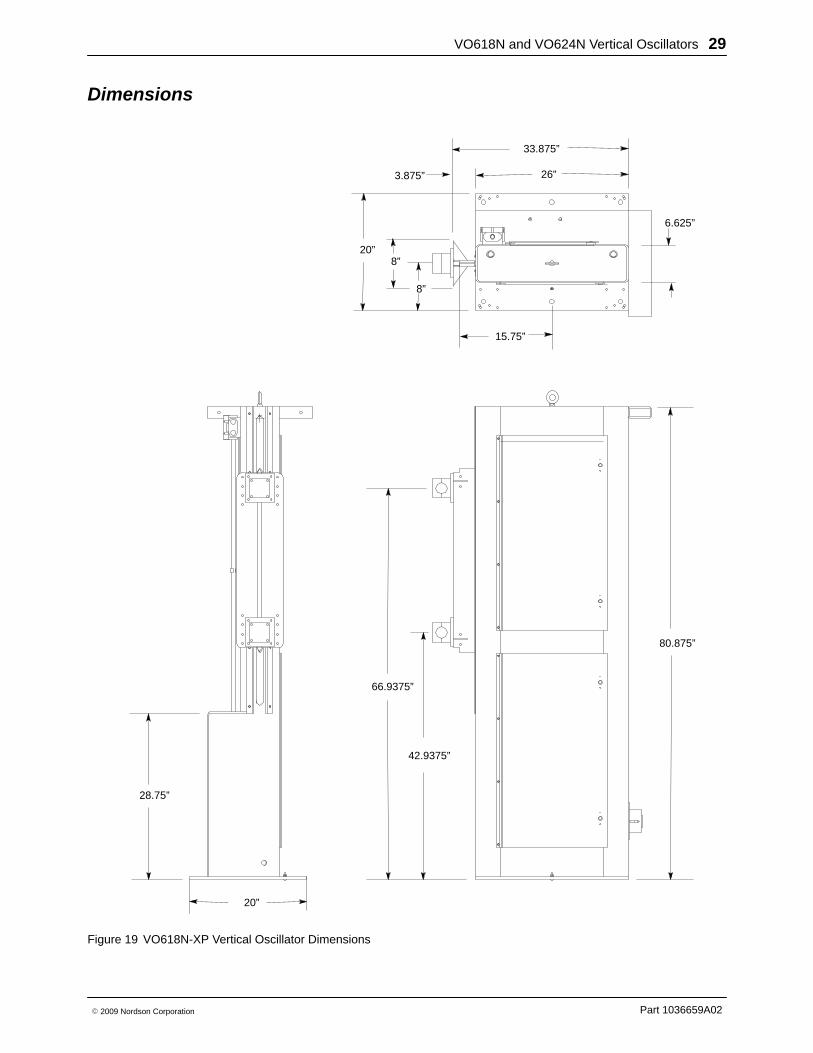
Dimensions
15.75”
26”
33.875”
20”
3.875”
80.875”
66.9375”
42.9375”
28.75”
20”
6.625”
8”
8”
Figure 19 VO618N-XP Vertical Oscillator Dimensions

VO618N and VO624N Vertical Oscillators30
Part 1036659A02 � 2009 Nordson Corporation


![[NIIR] the Complete Technology Book on Electroplating, Phosphating Powder Coating and Metal Finishing](https://img.pdfslide.us/doc/110x75/55720683497959fc0b8b9312/niir-the-complete-technology-book-on-electroplating-phosphating-powder-coating-and-metal-finishing.jpg)