Embed Size (px)
Citation preview
Excel 2000� SeriesPowder Coating System
Customer Product ManualPart 106641−04
Issued 09/17
NORDSON CORPORATION • AMHERST, OHIO • USA
For parts and technical support, call the Industrial CoatingSystems Customer Support Center at (800) 433-9319 or
contact your local Nordson representative.
This document is subject to change without notice.Check http://emanuals.nordson.com for the latest version.

Part 106641−04 � 2017 Nordson Corporation
Contact UsNordson Corporation welcomes requests for information, comments, andinquiries about its products. General information about Nordson can befound on the Internet using the following address:http://www.nordson.com.Address all correspondence to:
Nordson CorporationAttn: Customer Service555 Jackson StreetAmherst, OH 44001
NoticeThis is a Nordson Corporation publication which is protected by copyright.Original copyright date 1993. No part of this document may bephotocopied, reproduced, or translated to another language without theprior written consent of Nordson Corporation. The information containedin this publication is subject to change without notice.
Trademarks
Excel 2000, Nordson, the Nordson logo, PowderGrid, Smart-Coat,Sure Coat, Tribomatic, and Versa-Spray are registered trademarks ofNordson Corporation.
All other trademarks are the property of their respective owners.
Table of Contents i
Part 106641−04� 2017 Nordson Corporation
Table of Contents
Safety 1-1. . . . . . . . . . . . . . . . . . . . . . . . . . . . . . . . . . . . . . . . . . . . . . . . . .Introduction 1-1. . . . . . . . . . . . . . . . . . . . . . . . . . . . . . . . . . . . . . . . . . . . .Qualified Personnel 1-1. . . . . . . . . . . . . . . . . . . . . . . . . . . . . . . . . . . . . .Intended Use 1-1. . . . . . . . . . . . . . . . . . . . . . . . . . . . . . . . . . . . . . . . . . . .Regulations and Approvals 1-2. . . . . . . . . . . . . . . . . . . . . . . . . . . . . . . .Personal Safety 1-2. . . . . . . . . . . . . . . . . . . . . . . . . . . . . . . . . . . . . . . . .Fire Safety 1-2. . . . . . . . . . . . . . . . . . . . . . . . . . . . . . . . . . . . . . . . . . . . . .Grounding 1-3. . . . . . . . . . . . . . . . . . . . . . . . . . . . . . . . . . . . . . . . . . . . . .Action in the Event of a Malfunction 1-4. . . . . . . . . . . . . . . . . . . . . . . .Disposal 1-4. . . . . . . . . . . . . . . . . . . . . . . . . . . . . . . . . . . . . . . . . . . . . . . .
Description 2-1. . . . . . . . . . . . . . . . . . . . . . . . . . . . . . . . . . . . . . . . . . . . .Introduction 2-1. . . . . . . . . . . . . . . . . . . . . . . . . . . . . . . . . . . . . . . . . . . . .
System Configuration 2-1. . . . . . . . . . . . . . . . . . . . . . . . . . . . . . . . . .System Operation 2-2. . . . . . . . . . . . . . . . . . . . . . . . . . . . . . . . . . . . . . . .
Powder Application 2-2. . . . . . . . . . . . . . . . . . . . . . . . . . . . . . . . . . . .Powder Recovery and Reclaim 2-2. . . . . . . . . . . . . . . . . . . . . . . . . .
System Equipment 2-4. . . . . . . . . . . . . . . . . . . . . . . . . . . . . . . . . . . . . . .Recovery and Reclaim Equipment 2-4. . . . . . . . . . . . . . . . . . . . . . .Color Module 2-6. . . . . . . . . . . . . . . . . . . . . . . . . . . . . . . . . . . . . . . . .System Controls 2-8. . . . . . . . . . . . . . . . . . . . . . . . . . . . . . . . . . . . . . .Application Equipment 2-10. . . . . . . . . . . . . . . . . . . . . . . . . . . . . . . . .Typical System Options 2-12. . . . . . . . . . . . . . . . . . . . . . . . . . . . . . . .
System Electrical and Pneumatic Controls 2-14. . . . . . . . . . . . . . . . . .System Electrical Panel 2-14. . . . . . . . . . . . . . . . . . . . . . . . . . . . . . . .Pulse-Valve Timer Box 2-17. . . . . . . . . . . . . . . . . . . . . . . . . . . . . . . . .System Pneumatic Panel 2-18. . . . . . . . . . . . . . . . . . . . . . . . . . . . . . .Rotary Sieve Control Panel 2-19. . . . . . . . . . . . . . . . . . . . . . . . . . . . .
Operation 3-1. . . . . . . . . . . . . . . . . . . . . . . . . . . . . . . . . . . . . . . . . . . . . .New System Startup 3-1. . . . . . . . . . . . . . . . . . . . . . . . . . . . . . . . . . . . .
Set the Timers 3-1. . . . . . . . . . . . . . . . . . . . . . . . . . . . . . . . . . . . . . . .Set the Air Pressures 3-2. . . . . . . . . . . . . . . . . . . . . . . . . . . . . . . . . .Rotary Sieve Settings 3-2. . . . . . . . . . . . . . . . . . . . . . . . . . . . . . . . .Final Startup Steps 3-3. . . . . . . . . . . . . . . . . . . . . . . . . . . . . . . . . . . .Fan Damper Adjustment 3-5. . . . . . . . . . . . . . . . . . . . . . . . . . . . . . . .Vent-Assist Air Pressure Adjustment 3-5. . . . . . . . . . . . . . . . . . . . .Feed Hopper Level Sensor Calibration 3-6. . . . . . . . . . . . . . . . . . .
Daily Startup and Shutdown Procedures 3-7. . . . . . . . . . . . . . . . . . . .Startup 3-7. . . . . . . . . . . . . . . . . . . . . . . . . . . . . . . . . . . . . . . . . . . . . . .Shutdown 3-7. . . . . . . . . . . . . . . . . . . . . . . . . . . . . . . . . . . . . . . . . . . .
Changing Colors 3-8. . . . . . . . . . . . . . . . . . . . . . . . . . . . . . . . . . . . . . . . .Color Change: Reclaim-to-Reclaim 3-8. . . . . . . . . . . . . . . . . . . . .
Removing the Color Module and Feed Hopper 3-8. . . . . . . . . .Installing a New Color Module and Feed Hopper 3-10. . . . . . . .
Color Change: Reclaim to Non-Reclaim 3-14. . . . . . . . . . . . . . . . . .New Color Module with Attached Feed Hopper 3-14. . . . . . . . . .New Color Module with Portable Feed Hopper 3-14. . . . . . . . . .
Startup after Color Change 3-15. . . . . . . . . . . . . . . . . . . . . . . . . . . . .
Table of Contentsii
Part 106641−04 � 2017 Nordson Corporation
Maintenance 4-1. . . . . . . . . . . . . . . . . . . . . . . . . . . . . . . . . . . . . . . . . . .Daily Maintenance 4-1. . . . . . . . . . . . . . . . . . . . . . . . . . . . . . . . . . . . . . .
Cleaning 4-1. . . . . . . . . . . . . . . . . . . . . . . . . . . . . . . . . . . . . . . . . . . . .Daily Equipment Maintenance 4-2. . . . . . . . . . . . . . . . . . . . . . . . . . .
Weekly Maintenance 4-4. . . . . . . . . . . . . . . . . . . . . . . . . . . . . . . . . . . . .Periodic Maintenance 4-5. . . . . . . . . . . . . . . . . . . . . . . . . . . . . . . . . . . .Maintenance Check List 4-6. . . . . . . . . . . . . . . . . . . . . . . . . . . . . . . . . .
Troubleshooting 5-1. . . . . . . . . . . . . . . . . . . . . . . . . . . . . . . . . . . . . . . .Introduction 5-1. . . . . . . . . . . . . . . . . . . . . . . . . . . . . . . . . . . . . . . . . . . . .Troubleshooting Procedures 5-2. . . . . . . . . . . . . . . . . . . . . . . . . . . . . .Reversing Motor Direction 5-7. . . . . . . . . . . . . . . . . . . . . . . . . . . . . . . . .
Exhaust Fan Motor 5-7. . . . . . . . . . . . . . . . . . . . . . . . . . . . . . . . . . . .Sieve Motor 5-7. . . . . . . . . . . . . . . . . . . . . . . . . . . . . . . . . . . . . . . . . . .
System Schematics (Systems Made in 2003 and Later) 5-8. . . . . .Schematics (Pre-2003 Systems) 5-14. . . . . . . . . . . . . . . . . . . . . . . . . .
Repair 6-1. . . . . . . . . . . . . . . . . . . . . . . . . . . . . . . . . . . . . . . . . . . . . . . . .Final Filter Replacement 6-1. . . . . . . . . . . . . . . . . . . . . . . . . . . . . . . . .Cartridge Filter Replacement 6-3. . . . . . . . . . . . . . . . . . . . . . . . . . . . . .
Cartridge Filter Removal 6-3. . . . . . . . . . . . . . . . . . . . . . . . . . . . .Cartridge Filter Installation 6-4. . . . . . . . . . . . . . . . . . . . . . . . . . . .
Color Module Fluidizing Plate Replacement 6-5. . . . . . . . . . . . . . . . . .Systems Made in 2003 or Later 6-5. . . . . . . . . . . . . . . . . . . . . . . . .
Preparation 6-5. . . . . . . . . . . . . . . . . . . . . . . . . . . . . . . . . . . . . . . . .Replacement 6-5. . . . . . . . . . . . . . . . . . . . . . . . . . . . . . . . . . . . . . .
Systems Made Before 2003 6-7. . . . . . . . . . . . . . . . . . . . . . . . . . . .Preparation 6-7. . . . . . . . . . . . . . . . . . . . . . . . . . . . . . . . . . . . . . . . .Replacement 6-7. . . . . . . . . . . . . . . . . . . . . . . . . . . . . . . . . . . . . . .
Feed Hopper Fluidizing Plate Replacement 6-9. . . . . . . . . . . . . . . . . .Preparation 6-9. . . . . . . . . . . . . . . . . . . . . . . . . . . . . . . . . . . . . . . . . . .Replacement 6-9. . . . . . . . . . . . . . . . . . . . . . . . . . . . . . . . . . . . . . . . .
Vibratory Sieve Repair 6-11. . . . . . . . . . . . . . . . . . . . . . . . . . . . . . . . . . . .Pulse Valve Replacement 6-12. . . . . . . . . . . . . . . . . . . . . . . . . . . . . . . .V-Belt Replacement 6-15. . . . . . . . . . . . . . . . . . . . . . . . . . . . . . . . . . . . . .Motor and Motor Sheave Replacement 6-16. . . . . . . . . . . . . . . . . . . . .
Motor Replacement 6-16. . . . . . . . . . . . . . . . . . . . . . . . . . . . . . . . . . .Motor Removal 6-16. . . . . . . . . . . . . . . . . . . . . . . . . . . . . . . . . . . . .Motor Installation 6-16. . . . . . . . . . . . . . . . . . . . . . . . . . . . . . . . . . .
Motor Sheave Replacement 6-18. . . . . . . . . . . . . . . . . . . . . . . . . . . .Motor Sheave Removal 6-18. . . . . . . . . . . . . . . . . . . . . . . . . . . . .Motor Sheave Installation 6-18. . . . . . . . . . . . . . . . . . . . . . . . . . . .
Fan Replacement 6-20. . . . . . . . . . . . . . . . . . . . . . . . . . . . . . . . . . . . . . . .Fan Removal 6-20. . . . . . . . . . . . . . . . . . . . . . . . . . . . . . . . . . . . . . . . .Fan Installation 6-20. . . . . . . . . . . . . . . . . . . . . . . . . . . . . . . . . . . . . . .Fan Adjustment 6-20. . . . . . . . . . . . . . . . . . . . . . . . . . . . . . . . . . . . . . .
Fan Sheave Replacement 6-21. . . . . . . . . . . . . . . . . . . . . . . . . . . . . . . .Fan Sheave Removal 6-21. . . . . . . . . . . . . . . . . . . . . . . . . . . . . . . . . .Fan Sheave Installation 6-21. . . . . . . . . . . . . . . . . . . . . . . . . . . . . . . .
Table of Contents iii
Part 106641−04� 2017 Nordson Corporation
Fan Shaft and Bearing Replacement 6-23. . . . . . . . . . . . . . . . . . . . . . .Bearing Types 6-23. . . . . . . . . . . . . . . . . . . . . . . . . . . . . . . . . . . . . . . .Fan Shaft and Bearing Removal 6-23. . . . . . . . . . . . . . . . . . . . . . . .Fan Shaft and Bearing Installation 6-24. . . . . . . . . . . . . . . . . . . . . . .Fan Shaft and Bearing Adjustment:Excel 2001 6-27. . . . . . . . . . . . . . . . . . . . . . . . . . . . . . . . . . . . . . . . . . .
Old-Style Bearing and Fan Shaft Adjustment: Excel 2001 6-27. . . . . . . . . . . . . . . . . . . . . . . . . . . . .New-Style Bearing and Fan Shaft Adjustment: Excel 2001 6-28. . . . . . . . . . . . . . . . . . . . . . . . . . . . .
Fan Shaft and Bearing Adjustment: Excel 2002 and 2003 6-29. .Old-Style Bearing and Fan Shaft Adjustment: Excel 2002 and 2003 6-29. . . . . . . . . . . . . . . . . . . . .New-Style Bearing and Fan Shaft Adjustment:Excel 2002 and 2003 6-30. . . . . . . . . . . . . . . . . . . . .
Parts 7-1. . . . . . . . . . . . . . . . . . . . . . . . . . . . . . . . . . . . . . . . . . . . . . . . . . .Introduction 7-1. . . . . . . . . . . . . . . . . . . . . . . . . . . . . . . . . . . . . . . . . . . . .Electrical Sub-Panel Parts (Systems Made in 2003 and Later) 7-1.Electrical Sub-Panel (Pre-2003 Systems) 7-5. . . . . . . . . . . . . . . . . . .Fan Section Supports and Miscellaneous Parts 7-9. . . . . . . . . . . . . .Final Filters and Miscellaneous Parts 7-11. . . . . . . . . . . . . . . . . . . . . .Pulse Valve and Solenoids 7-13. . . . . . . . . . . . . . . . . . . . . . . . . . . . . . . .Fan Damper and Manual Control 7-15. . . . . . . . . . . . . . . . . . . . . . . . . . .Pneumatic Seal 7-16. . . . . . . . . . . . . . . . . . . . . . . . . . . . . . . . . . . . . . . . . .Color Module Cartridge Filters and Fluidizing Plates (Systems Made in 2003 and Later) 7-17. . . . . . . . . . . . . . . . . . .
Color Module Covers and Caster Parts 7-19. . . . . . . . . . . . . . . . . . .Color Module Cartridge Filters and Fluidizing Plates (Pre-2003 Systems) 7-21. . . . . . . . . . . . . . . . . . . . . . . . . . . . . . . .
Color Module Covers and Casters 7-23. . . . . . . . . . . . . . . . . . . . . . .Pneumatic Control Panel 7-25. . . . . . . . . . . . . . . . . . . . . . . . . . . . . . . . . .Fan and Fan Drive 7-27. . . . . . . . . . . . . . . . . . . . . . . . . . . . . . . . . . . . . .
Bushing and Sheave Part Numbers 7-28. . . . . . . . . . . . . . . . . . . . . .
Specifications 8-1. . . . . . . . . . . . . . . . . . . . . . . . . . . . . . . . . . . . . . . . . .Dimensions and Capacities 8-1. . . . . . . . . . . . . . . . . . . . . . . . . . . . . . . .Operating Environment 8-1. . . . . . . . . . . . . . . . . . . . . . . . . . . . . . . . . . .Utilities 8-2. . . . . . . . . . . . . . . . . . . . . . . . . . . . . . . . . . . . . . . . . . . . . . . . .Normal Design Standards 8-2. . . . . . . . . . . . . . . . . . . . . . . . . . . . . . . . .
Split Support Beam Installation 9-1. . . . . . . . . . . . . . . . . . . . . . . . . .Split Support Beam Installation−Fixed Booths 9-1. . . . . . . . . . . . . . .Split Support Beam Installation− Roll-On/Roll-Off Booths 9-3. . . . .Split Support Beam Installation−Booths with Integral Booth Mover 9-5. . . . . . . . . . . . . . . . . . . . . . . . . .
Table of Contentsiv
Part 106641−04 � 2017 Nordson Corporation
Safety 1-1
Part 106641−04� 2017 Nordson Corporation
Section 1Safety
IntroductionRead and follow these safety instructions. Task- and equipment-specificwarnings, cautions, and instructions are included in equipmentdocumentation where appropriate.
Make sure all equipment documentation, including these instructions, isaccessible to all persons operating or servicing equipment.
Qualified PersonnelEquipment owners are responsible for making sure that Nordson equipmentis installed, operated, and serviced by qualified personnel. Qualifiedpersonnel are those employees or contractors who are trained to safelyperform their assigned tasks. They are familiar with all relevant safety rulesand regulations and are physically capable of performing their assignedtasks.
Intended UseUse of Nordson equipment in ways other than those described in thedocumentation supplied with the equipment may result in injury to personsor damage to property.
Some examples of unintended use of equipment include
� using incompatible materials
� making unauthorized modifications
� removing or bypassing safety guards or interlocks
� using incompatible or damaged parts
� using unapproved auxiliary equipment
� operating equipment in excess of maximum ratings
Safety1-2
Part 106641−04 � 2017 Nordson Corporation
Regulations and ApprovalsMake sure all equipment is rated and approved for the environment in whichit is used. Any approvals obtained for Nordson equipment will be voided ifinstructions for installation, operation, and service are not followed.
All phases of equipment installation must comply with all federal, state, andlocal codes.
Personal SafetyTo prevent injury follow these instructions.
� Do not operate or service equipment unless you are qualified.
� Do not operate equipment unless safety guards, doors, or covers areintact and automatic interlocks are operating properly. Do not bypass ordisarm any safety devices.
� Keep clear of moving equipment. Before adjusting or servicing anymoving equipment, shut off the power supply and wait until theequipment comes to a complete stop. Lock out power and secure theequipment to prevent unexpected movement.
� Relieve (bleed off) hydraulic and pneumatic pressure before adjusting orservicing pressurized systems or components. Disconnect, lock out,and tag switches before servicing electrical equipment.
� Obtain and read Safety Data Sheets (SDS) for all materials used.Follow the manufacturer’s instructions for safe handling and use ofmaterials, and use recommended personal protection devices.
� To prevent injury, be aware of less-obvious dangers in the workplacethat often cannot be completely eliminated, such as hot surfaces, sharpedges, energized electrical circuits, and moving parts that cannot beenclosed or otherwise guarded for practical reasons.
Fire SafetyTo avoid a fire or explosion, follow these instructions.
� Do not smoke, weld, grind, or use open flames where flammablematerials are being used or stored.
� Provide adequate ventilation to prevent dangerous concentrations ofvolatile materials or vapors. Refer to local codes or your material SDSfor guidance.
� Do not disconnect live electrical circuits while working with flammablematerials. Shut off power at a disconnect switch first to preventsparking.
Safety 1-3
Part 106641−04� 2017 Nordson Corporation
� Know where emergency stop buttons, shutoff valves, and fireextinguishers are located. If a fire starts in a spray booth, immediatelyshut off the spray system and exhaust fans.
� Clean, maintain, test, and repair equipment according to the instructionsin your equipment documentation.
� Use only replacement parts that are designed for use with originalequipment. Contact your Nordson representative for parts informationand advice.
Grounding
WARNING: Operating faulty electrostatic equipment is hazardous and cancause electrocution, fire, or explosion. Make resistance checks part of yourperiodic maintenance program. If you receive even a slight electrical shockor notice static sparking or arcing, shut down all electrical or electrostaticequipment immediately. Do not restart the equipment until the problem hasbeen identified and corrected.
All work conducted inside the spray booth or within 1 m (3 ft) of boothopenings is considered within a Class 2, Division 1 or 2 Hazardous locationand must comply with NFPA 33, NFPA 70 (NEC articles 500, 502, and 516),and NFPA 77, latest conditions.
� All electrically conductive objects in the spray areas shall be electricallyconnected to ground with a resistance of not more than 1 megohm asmeasured with an instrument that applies at least 500 volts to the circuitbeing evaluated.
� Equipment to be grounded includes, but is not limited to, the floor of thespray area, operator platforms, hoppers, photoeye supports, andblow-off nozzles. Personnel working in the spray area must begrounded.
� There is a possible ignition potential from the charged human body.Personnel standing on a painted surface, such as an operator platform,or wearing non-conductive shoes, are not grounded. Personnel mustwear shoes with conductive soles or use a ground strap to maintain aconnection to ground when working with or around electrostaticequipment.
� Operators must maintain skin-to-handle contact between their hand andthe gun handle to prevent shocks while operating manual electrostaticspray guns. If gloves must be worn, cut away the palm or fingers, wearelectrically conductive gloves, or wear a grounding strap connected tothe gun handle or other true earth ground.
� Shut off electrostatic power supplies and ground gun electrodes beforemaking adjustments or cleaning powder spray guns.
� Connect all disconnected equipment, ground cables, and wires afterservicing equipment.
Safety1-4
Part 106641−04 � 2017 Nordson Corporation
Action in the Event of a MalfunctionIf a system or any equipment in a system malfunctions, shut off the systemimmediately and perform the following steps:
� Disconnect and lock out electrical power. Close pneumatic shutoffvalves and relieve pressures.
� Identify the reason for the malfunction and correct it before restarting theequipment.
DisposalDispose of equipment and materials used in operation and servicingaccording to local codes.
Description 2-1
Part 106641−04� 2017 Nordson Corporation
Section 2Description
IntroductionThis manual covers Excel 2001, 2002, and 2003 powder coating systems.It includes system operation, maintenance, and troubleshooting procedures.Spray booth repair procedures and parts lists are also included. Reviewthis manual and the manuals for the other components of your systembefore operating your Nordson powder coating system.
NOTE: For systems manufactured after 2003, refer to the supplementincluded with this manual for information on updates to the electrical panel,wiring diagrams, and color module.
System ConfigurationA complete powder coating system consists of powder applicationequipment and powder recovery/reclaim equipment. Since powder coatingsystems are designed to each customer’s requirements, each system willhave a different combination of equipment. This manual describes a basic,manually operated system. Your system may have equipment notdescribed in this manual, such as automatic gun triggering and airmanagement systems. Before operating your system, please read themanuals for all equipment not covered in this manual.
The system can be permanently located under the conveyor, or mounted oncasters and rails (roll-on/roll-off system). A roll-on/roll-off system has railsand casters added, to allow it to be moved off-line for powder changes ormaintenance. The illustrations in this section show a roll-on/roll-off system.
Figure 2-1 illustrates the operation of the typical system. Figures 2-2, 2-4,and 2-5 shows the locations of the components in a typical system.
Description2-2
Part 106641−04 � 2017 Nordson Corporation
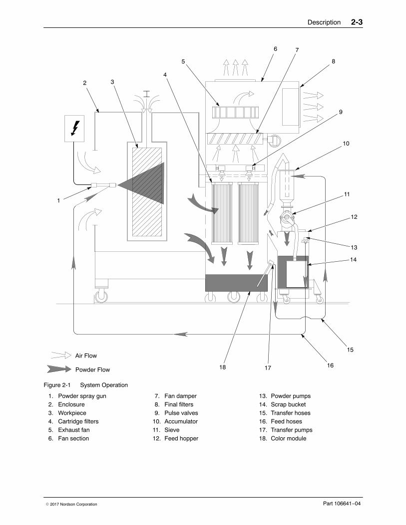
System OperationSee Figure 2-1.
Powder ApplicationA porous fluidizing plate in the bottom of the feed hopper (12) diffuseslow-pressure compressed air into the powder supply. The air fluidizes thepowder so it can be pumped to the spray guns. The fluidizing air flows intothe color module (18) through a vent duct. In the color module, thecartridge filters separate powder dust from the fluidizing air.
The powder pumps (13) draw the powder out of the hopper, mix it with ahigh-velocity stream of air, and force it through feed hoses (16) to thepowder spray guns (1). The spray guns electrostatically charge the powderand spray it onto the workpieces (3) passing through the booth. Thecharged powder sticks to the grounded workpieces.
Powder Recovery and ReclaimAn exhaust fan (5) pulls spray-room air into the enclosure (2), through thecartridge filters (4) and color module, and into the fan section (6). The airreturns to the spray room through the final filters (8), free of all powder. Thefan damper (7) controls the volume of air flowing through the booth.
Most of the oversprayed powder remains suspended in the air flowingthrough the enclosure to the cartridge filters. The powder collects on theexternal surfaces of the cartridge filters. At timed intervals, the pulsevalves (9) release large volumes of air through the centers of the cartridgefilters. The air pulse blows the powder off the filters. The powder falls intothe color module hoppers, where it is fluidized.
The transfer pumps (17) pump the reclaimed powder through the transferhoses (15) to the accumulator (10) on top of the sieve (11). The sievescreens the reclaimed powder and discharges particles and clumps toolarge to pass through the sieve screen into a scrap bucket (14). The rest ofthe reclaimed powder falls into the feed hopper. A vent tube connects theaccumulator to the color module. Venting prevents the transfer pump airfrom blowing the powder through the sieve screen and into the scrapbucket.
Description 2-3
Part 106641−04� 2017 Nordson Corporation
1
24
5
6 7
8
9
10
11
12
13
14
15
161718
3
Air Flow
Powder Flow
Figure 2-1 System Operation
1. Powder spray gun2. Enclosure3. Workpiece4. Cartridge filters5. Exhaust fan6. Fan section
7. Fan damper8. Final filters9. Pulse valves
10. Accumulator11. Sieve12. Feed hopper
13. Powder pumps14. Scrap bucket15. Transfer hoses16. Feed hoses17. Transfer pumps18. Color module
Description2-4
Part 106641−04 � 2017 Nordson Corporation
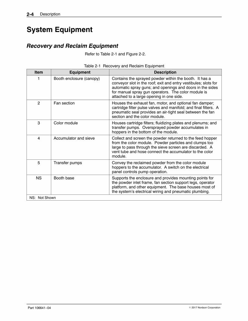
System Equipment
Recovery and Reclaim EquipmentRefer to Table 2-1 and Figure 2-2.
Table 2-1 Recovery and Reclaim Equipment
Item Equipment Description
1 Booth enclosure (canopy) Contains the sprayed powder within the booth. It has aconveyor slot in the roof; exit and entry vestibules; slots forautomatic spray guns; and openings and doors in the sidesfor manual spray gun operators. The color module isattached to a large opening in one side.
2 Fan section Houses the exhaust fan, motor, and optional fan damper;cartridge filter pulse valves and manifold; and final filters. Apneumatic seal provides an air-tight seal between the fansection and the color module.
3 Color module Houses cartridge filters; fluidizing plates and plenums; andtransfer pumps. Oversprayed powder accumulates inhoppers in the bottom of the module.
4 Accumulator and sieve Collect and screen the powder returned to the feed hopperfrom the color module. Powder particles and clumps toolarge to pass through the sieve screen are discarded. Avent tube and hose connect the accumulator to the colormodule.
5 Transfer pumps Convey the reclaimed powder from the color modulehoppers to the accumulator. A switch on the electricalpanel controls pump operation.
NS Booth base Supports the enclosure and provides mounting points forthe powder inlet frame, fan section support legs, operatorplatform, and other equipment. The base houses most ofthe system’s electrical wiring and pneumatic plumbing.
NS: Not Shown
Description 2-5
Part 106641−04� 2017 Nordson Corporation
1
2
3
4
5
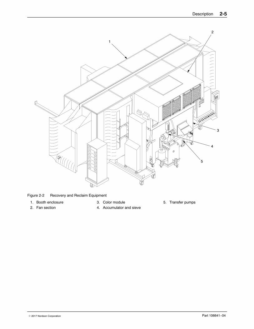
Figure 2-2 Recovery and Reclaim Equipment
1. Booth enclosure2. Fan section
3. Color module4. Accumulator and sieve
5. Transfer pumps
Description2-6
Part 106641−04 � 2017 Nordson Corporation
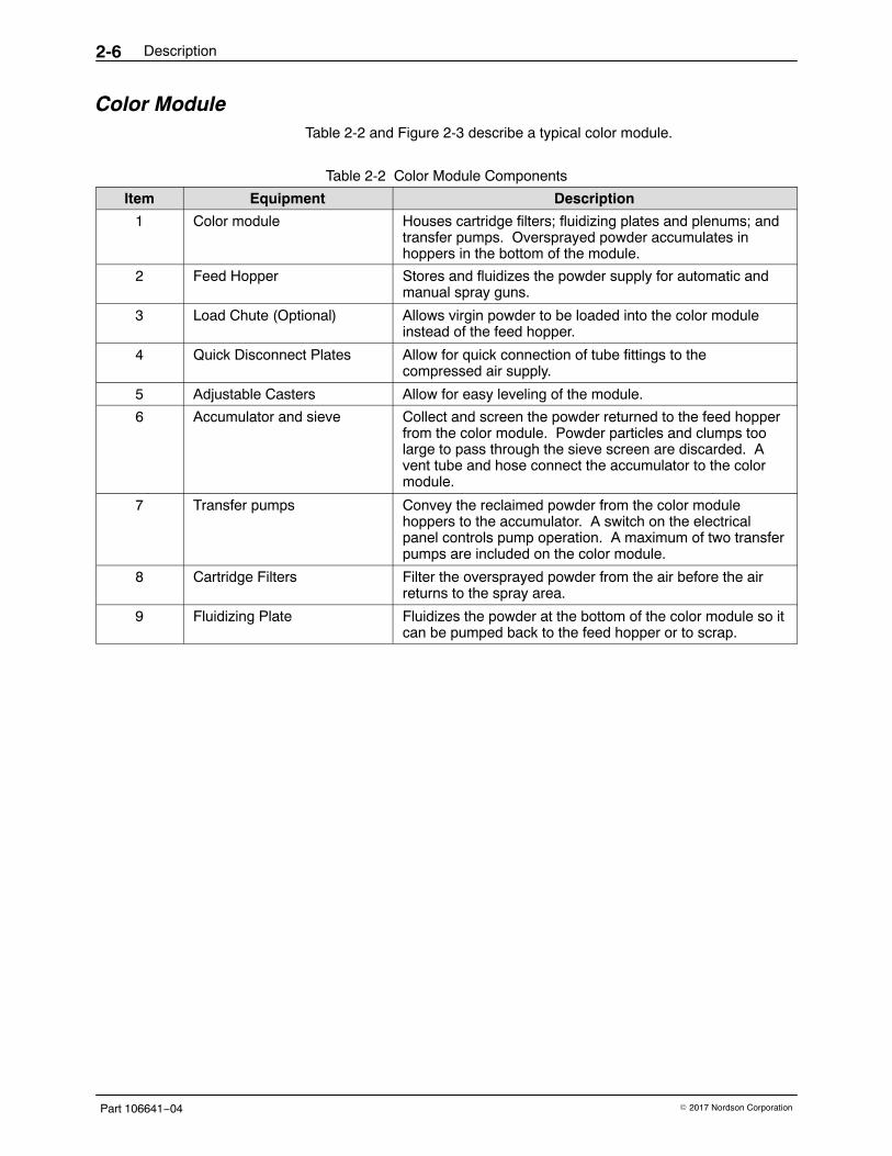
Color Module Table 2-2 and Figure 2-3 describe a typical color module.
Table 2-2 Color Module Components
Item Equipment Description
1 Color module Houses cartridge filters; fluidizing plates and plenums; andtransfer pumps. Oversprayed powder accumulates inhoppers in the bottom of the module.
2 Feed Hopper Stores and fluidizes the powder supply for automatic andmanual spray guns.
3 Load Chute (Optional) Allows virgin powder to be loaded into the color moduleinstead of the feed hopper.
4 Quick Disconnect Plates Allow for quick connection of tube fittings to thecompressed air supply.
5 Adjustable Casters Allow for easy leveling of the module.
6 Accumulator and sieve Collect and screen the powder returned to the feed hopperfrom the color module. Powder particles and clumps toolarge to pass through the sieve screen are discarded. Avent tube and hose connect the accumulator to the colormodule.
7 Transfer pumps Convey the reclaimed powder from the color modulehoppers to the accumulator. A switch on the electricalpanel controls pump operation. A maximum of two transferpumps are included on the color module.
8 Cartridge Filters Filter the oversprayed powder from the air before the airreturns to the spray area.
9 Fluidizing Plate Fluidizes the powder at the bottom of the color module so itcan be pumped back to the feed hopper or to scrap.
Description 2-7
Part 106641−04� 2017 Nordson Corporation
5
3 2
1
8
1
9
7
6
4
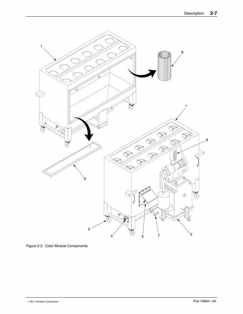
Figure 2-3 Color Module Components
Description2-8
Part 106641−04 � 2017 Nordson Corporation
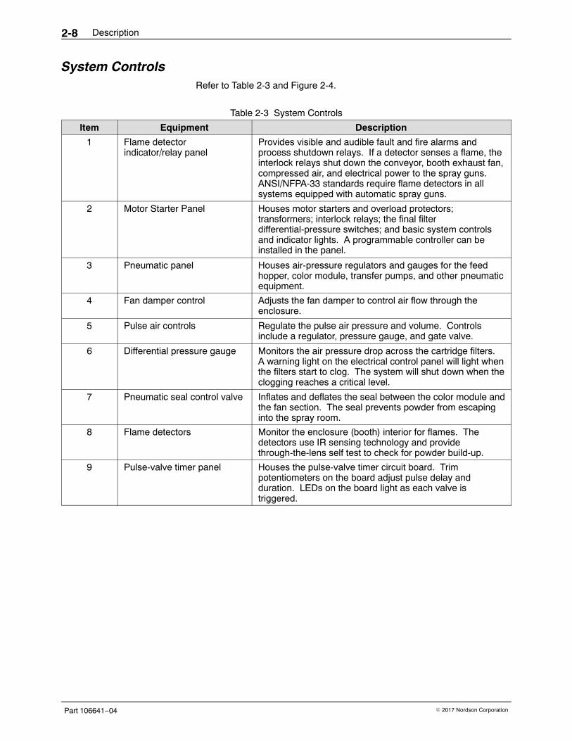
System ControlsRefer to Table 2-3 and Figure 2-4.
Table 2-3 System Controls
Item Equipment Description
1 Flame detectorindicator/relay panel
Provides visible and audible fault and fire alarms andprocess shutdown relays. If a detector senses a flame, theinterlock relays shut down the conveyor, booth exhaust fan,compressed air, and electrical power to the spray guns.ANSI/NFPA-33 standards require flame detectors in allsystems equipped with automatic spray guns.
2 Motor Starter Panel Houses motor starters and overload protectors;transformers; interlock relays; the final filterdifferential-pressure switches; and basic system controlsand indicator lights. A programmable controller can beinstalled in the panel.
3 Pneumatic panel Houses air-pressure regulators and gauges for the feedhopper, color module, transfer pumps, and other pneumaticequipment.
4 Fan damper control Adjusts the fan damper to control air flow through theenclosure.
5 Pulse air controls Regulate the pulse air pressure and volume. Controlsinclude a regulator, pressure gauge, and gate valve.
6 Differential pressure gauge Monitors the air pressure drop across the cartridge filters.A warning light on the electrical control panel will light whenthe filters start to clog. The system will shut down when theclogging reaches a critical level.
7 Pneumatic seal control valve Inflates and deflates the seal between the color module andthe fan section. The seal prevents powder from escapinginto the spray room.
8 Flame detectors Monitor the enclosure (booth) interior for flames. Thedetectors use IR sensing technology and providethrough-the-lens self test to check for powder build-up.
9 Pulse-valve timer panel Houses the pulse-valve timer circuit board. Trimpotentiometers on the board adjust pulse delay andduration. LEDs on the board light as each valve istriggered.
Description 2-9
Part 106641−04� 2017 Nordson Corporation
3
2
1
9
8
7 6
5
4
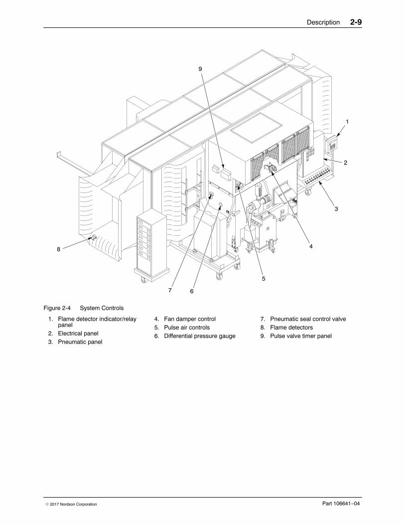
Figure 2-4 System Controls
1. Flame detector indicator/relaypanel
2. Electrical panel3. Pneumatic panel
4. Fan damper control5. Pulse air controls6. Differential pressure gauge
7. Pneumatic seal control valve8. Flame detectors9. Pulse valve timer panel
Description2-10
Part 106641−04 � 2017 Nordson Corporation
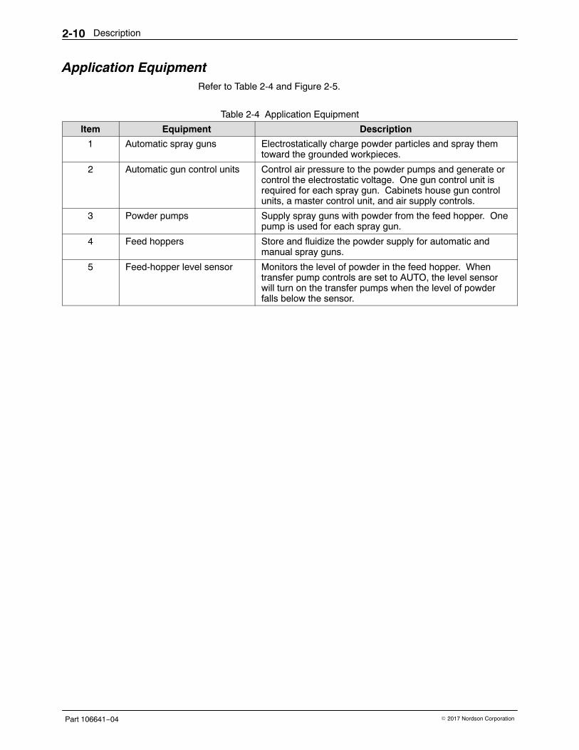
Application EquipmentRefer to Table 2-4 and Figure 2-5.
Table 2-4 Application Equipment
Item Equipment Description
1 Automatic spray guns Electrostatically charge powder particles and spray themtoward the grounded workpieces.
2 Automatic gun control units Control air pressure to the powder pumps and generate orcontrol the electrostatic voltage. One gun control unit isrequired for each spray gun. Cabinets house gun controlunits, a master control unit, and air supply controls.
3 Powder pumps Supply spray guns with powder from the feed hopper. Onepump is used for each spray gun.
4 Feed hoppers Store and fluidize the powder supply for automatic andmanual spray guns.
5 Feed-hopper level sensor Monitors the level of powder in the feed hopper. Whentransfer pump controls are set to AUTO, the level sensorwill turn on the transfer pumps when the level of powderfalls below the sensor.
Description 2-11
Part 106641−04� 2017 Nordson Corporation
4
1
32
5
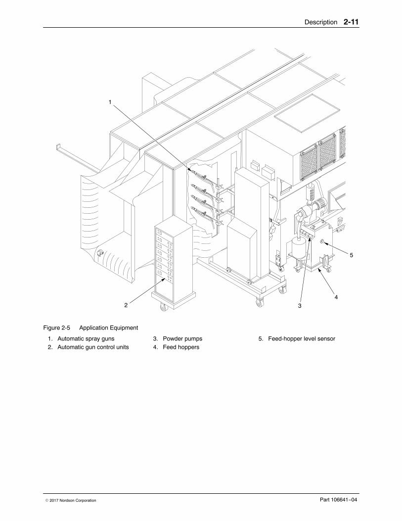
Figure 2-5 Application Equipment
1. Automatic spray guns2. Automatic gun control units
3. Powder pumps4. Feed hoppers
5. Feed-hopper level sensor
Description2-12
Part 106641−04 � 2017 Nordson Corporation
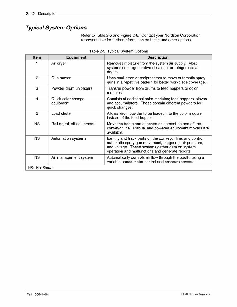
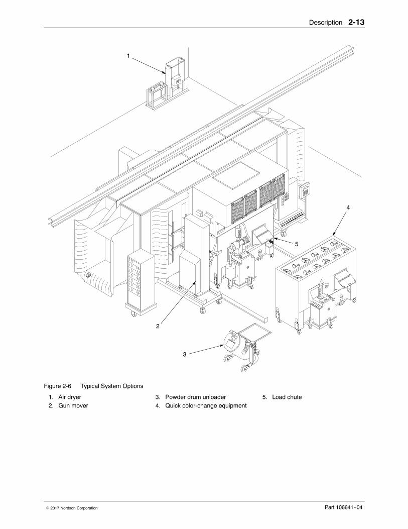
Typical System OptionsRefer to Table 2-5 and Figure 2-6. Contact your Nordson Corporationrepresentative for further information on these and other options.
Table 2-5 Typical System Options
Item Equipment Description
1 Air dryer Removes moisture from the system air supply. Mostsystems use regenerative-desiccant or refrigerated airdryers.
2 Gun mover Uses oscillators or reciprocators to move automatic sprayguns in a repetitive pattern for better workpiece coverage.
3 Powder drum unloaders Transfer powder from drums to feed hoppers or colormodules.
4 Quick color changeequipment
Consists of additional color modules; feed hoppers; sievesand accumulators. These contain different powders forquick changes.
5 Load chute Allows virgin powder to be loaded into the color moduleinstead of the feed hopper.
NS Roll on/roll-off equipment Move the booth and attached equipment on and off theconveyor line. Manual and powered equipment movers areavailable.
NS Automation systems Identify and track parts on the conveyor line; and controlautomatic-spray gun movement, triggering, air pressure,and voltage. These systems gather data on systemoperation and malfunctions and generate reports.
NS Air management system Automatically controls air flow through the booth, using avariable-speed motor control and pressure sensors.
NS: Not Shown
Description 2-13
Part 106641−04� 2017 Nordson Corporation
1
2
3
4
5
Figure 2-6 Typical System Options
1. Air dryer2. Gun mover
3. Powder drum unloader4. Quick color-change equipment
5. Load chute
Description2-14
Part 106641−04 � 2017 Nordson Corporation
System Electrical and Pneumatic ControlsBasic system controls consist of an electrical panel, a pulse-valve timer box,and a pneumatic panel. Additional optional controls are covered in separatemanuals.
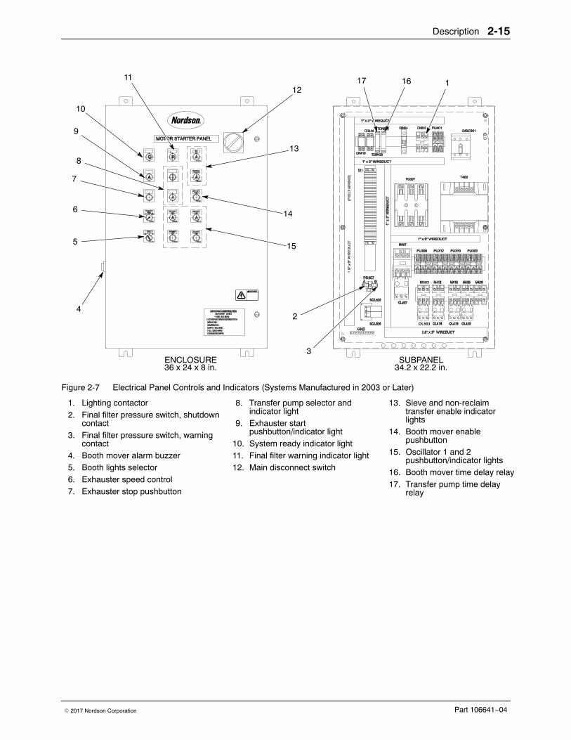
System Electrical Panel Refer to Table 2-6 and Figures 2-7 (systems made in 2003 and later) and2-8 (pre-2003 systems). Your system electrical panel may be different.
Table 2-6 System Electrical Panel
Item Equipment Description
1, 5 Booth lights selector (5) NOTE: Power to the lights must be supplied by thecustomer.
Activates the lighting contactor (1) for interior booth lights.
2, 3, 11 Final filter pressure switch Preset to activate contacts on increasing pressure acrossthe final filters. At 2.5-in. w.c., the final filter warningpressure switch contact (3) closes and activates the finalfilter warning indicator light (11). At 3-in. w.c., the final filterpressure switch contact (2) opens and automatically shutsdown the system.
4, 14, 16 Booth mover enablepushbutton (14)
Activates the booth mover time delay relay (16). During thetimer delay, the booth mover alarm buzzer (4) sounds, andthe system can be moved online or offline.
6 Exhauster speed control Used with the variable frequency drive to adjust theexhauster fan speed.
7 Exhauster stop pushbutton NOTE: This pushbutton does not shut down power to thepanel.
Shuts down the exhauster fan and system.
8, 17 Transfer pump selector andindicator light (8)
Selects the transfer pump operation. When set to manual,the transfer pumps run continuously. When set to autofeed, the hopper level sensor and time delay relay (17)control the pump operation.
9 Exhauster startpushbutton/indicator light
Starts the exhauster fan and indicates that system power ison.
10 System ready indicator light Indicates, when lit, that the fire detection module limitswitch and air dryer interlocks are closed and that thesystem is ready to start.
12 Main disconnect switch Turns the motor starter panel electrical power on or off.
13 Sieve and non-reclaimtransfer enable indicatorlights
The sieve light indicates that the sieve is in place andrunning. The non-reclaim enabled transfer light indicatesthat the system can transfer powder without the sieve inplace.
15 Oscillator 1 and 2pushbuttons/indicator lights
Turn the oscillators on or off.
Description 2-15
Part 106641−04� 2017 Nordson Corporation
OL503
17
3
16 1
2
10
11
9
8
7
6
5
4
15
14
13
12
ENCLOSURE36 x 24 x 8 in.
SUBPANEL34.2 x 22.2 in.
M503
Figure 2-7 Electrical Panel Controls and Indicators (Systems Manufactured in 2003 or Later)
1. Lighting contactor2. Final filter pressure switch, shutdown
contact3. Final filter pressure switch, warning
contact4. Booth mover alarm buzzer5. Booth lights selector6. Exhauster speed control7. Exhauster stop pushbutton
8. Transfer pump selector andindicator light
9. Exhauster startpushbutton/indicator light
10. System ready indicator light11. Final filter warning indicator light12. Main disconnect switch
13. Sieve and non-reclaimtransfer enable indicatorlights
14. Booth mover enablepushbutton
15. Oscillator 1 and 2pushbutton/indicator lights
16. Booth mover time delay relay17. Transfer pump time delay
relay
Description2-16
Part 106641−04 � 2017 Nordson Corporation
1
2
3
16
15
14
17
13
12
11
9
10
8
7
6
4
5
ENCLOSURE36 x 24 x 8 in.
SUBPANEL33 x 21 in.
AH427
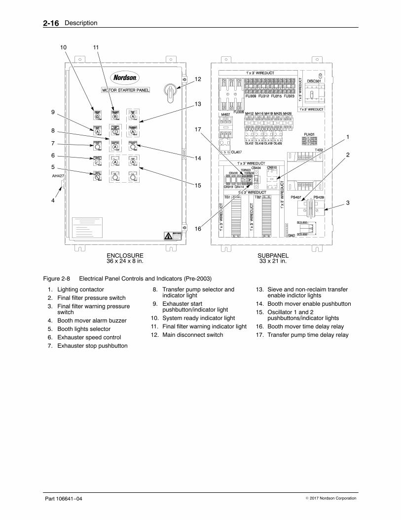
Figure 2-8 Electrical Panel Controls and Indicators (Pre-2003)
1. Lighting contactor2. Final filter pressure switch3. Final filter warning pressure
switch4. Booth mover alarm buzzer5. Booth lights selector6. Exhauster speed control7. Exhauster stop pushbutton
8. Transfer pump selector andindicator light
9. Exhauster startpushbutton/indicator light
10. System ready indicator light11. Final filter warning indicator light12. Main disconnect switch
13. Sieve and non-reclaim transferenable indictor lights
14. Booth mover enable pushbutton15. Oscillator 1 and 2
pushbuttons/indicator lights16. Booth mover time delay relay17. Transfer pump time delay relay
Description 2-17
Part 106641−04� 2017 Nordson Corporation
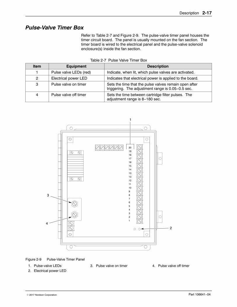
Pulse-Valve Timer BoxRefer to Table 2-7 and Figure 2-9. The pulse-valve timer panel houses thetimer circuit board. The panel is usually mounted on the fan section. Thetimer board is wired to the electrical panel and the pulse-valve solenoidenclosure(s) inside the fan section.
Table 2-7 Pulse Valve Timer Box
Item Equipment Description
1 Pulse valve LEDs (red) Indicate, when lit, which pulse valves are activated.
2 Electrical power LED Indicates that electrical power is applied to the board.
3 Pulse valve on timer Sets the time that the pulse valves remain open aftertriggering. The adjustment range is 0.05−0.5 sec.
4 Pulse valve off timer Sets the time between cartridge filter pulses. Theadjustment range is 8−180 sec.
42
1
3
20
19
18
17
16
15
14
13
13
12
11
10
9
8
7
6
5
4
3
2
1
Figure 2-9 Pulse-Valve Timer Panel
1. Pulse-valve LEDs2. Electrical power LED
3. Pulse valve on timer 4. Pulse valve off timer
Description2-18
Part 106641−04 � 2017 Nordson Corporation
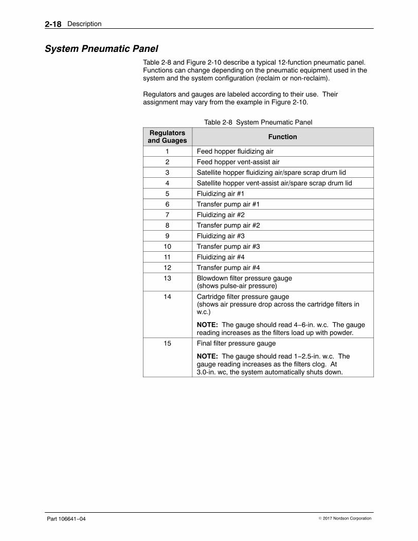
System Pneumatic PanelTable 2-8 and Figure 2-10 describe a typical 12-function pneumatic panel.Functions can change depending on the pneumatic equipment used in thesystem and the system configuration (reclaim or non-reclaim).
Regulators and gauges are labeled according to their use. Theirassignment may vary from the example in Figure 2-10.
Table 2-8 System Pneumatic Panel
Regulatorsand Guages Function
1 Feed hopper fluidizing air
2 Feed hopper vent-assist air
3 Satellite hopper fluidizing air/spare scrap drum lid
4 Satellite hopper vent-assist air/spare scrap drum lid
5 Fluidizing air #1
6 Transfer pump air #1
7 Fluidizing air #2
8 Transfer pump air #2
9 Fluidizing air #3
10 Transfer pump air #3
11 Fluidizing air #4
12 Transfer pump air #4
13 Blowdown filter pressure gauge(shows pulse-air pressure)
14 Cartridge filter pressure gauge(shows air pressure drop across the cartridge filters inw.c.)
NOTE: The gauge should read 4−6-in. w.c. The gaugereading increases as the filters load up with powder.
15 Final filter pressure gauge
NOTE: The gauge should read 1−2.5-in. w.c. Thegauge reading increases as the filters clog. At3.0-in. wc, the system automatically shuts down.
Description 2-19
Part 106641−04� 2017 Nordson Corporation
13
2 3 5 7 9 11
124 6 8 10
1
15 14
PNEUMATIC PANEL
Figure 2-10 System Pneumatic Panel
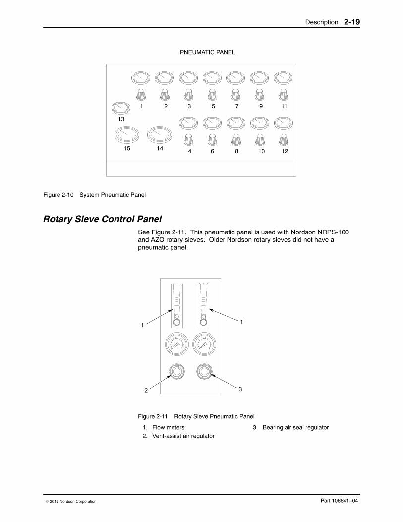
Rotary Sieve Control PanelSee Figure 2-11. This pneumatic panel is used with Nordson NRPS-100and AZO rotary sieves. Older Nordson rotary sieves did not have apneumatic panel.
1
2 3
1
Figure 2-11 Rotary Sieve Pneumatic Panel
1. Flow meters2. Vent-assist air regulator
3. Bearing air seal regulator
Description2-20
Part 106641−04 � 2017 Nordson Corporation
Operation 3-1
Part 106641−04� 2017 Nordson Corporation
Section 3Operation
WARNING: Allow only qualified personnel to perform the following tasks.Follow the safety instructions in this document and all other relateddocumentation.
New System Startup Use these procedures to prepare your Excel 2000 powder coating systemfor production operations. Refer to the appropriate manuals for instructionsif your system is equipped with a Smart-Spray or Smart-Coat system, oranother type of automation system.
Your Nordson Corporation representative will help you set up yourapplication equipment and adjust your system control settings before youstart powder coating your products. Record the system settings on thecharts provided at the end of this section. Make extra copies of the chartsas needed.
NOTE: Since powder coating systems are custom-designed to eachcustomer’s requirements, each system will have a different combination ofequipment. Your system may have equipment not described in this manual,such as automatic gun-triggering and air-management systems.
WARNING: Even with the electrical panel disconnect in the off position, theinput terminals at the top of the switch are still live. Do not touch them.Failure to observe this warning could result in serious injury or death.
See Figure 3-1.
Set the Timers 1. Disconnect the system electrical power and open the system electrical
panel (2).
2. Set the transfer-pump delay to 60 seconds (see Figure 2-8, (17)). Closethe electrical panel.
3. Open the pulse-valve timer panel (9). Set the pulse-valve off timer (seeFigure 2-9, (4) to 15 seconds and the pulse valve on timer(see Figure 2-9, (3))to duration to 0.07 seconds . Close the timer panel.
Operation3-2
Part 106641−04 � 2017 Nordson Corporation
Set the Air Pressures 1. Set all air pressure regulators on the pneumatic panel (3) to zero.
2. Turn on the compressed air supply. Adjust the system air pressureto 5.5 bar (80 psi).
3. Turn on the system electrical power.
4. Use the seal control valve (7) to inflate the pneumatic seal between thecolor module and the fan section. Make sure the seal is pressingagainst the top of color module equally on all four sides
5. Turn on the exhaust fan (see Figure 2-8, (9)).
WARNING: Wear a NIOSH-approved respirator or dust mask and safetyglasses or goggles when handling powder. Avoid getting powder on yourskin. Wash powder off with soap and water only.
6. Open the feed hopper access door (6). Fill the hopper 2/3 full of powder.
7. Calibrate the feed hopper level sensor. Refer to Feed Hopper LevelSensor Calibration in this section.
8. Set the feed hopper fluidizing air pressure to 0.6 bar (8 psi). Adjust thepressure until you see the powder gently boiling. Allow 10−15 minutesfor the powder to fluidize before spraying.
9. Set the color module fluidizing air pressure to 0.7 bar (10 psi). Whenpowder covers the fluidizing plates in the bottom of the color modulehoppers, adjust the pressure. You should see the powder gently boiling.
Rotary Sieve Settings NOTE: Sieve operation depends on system configuration. In somesystems, the sieve turns on when the exhaust fan is started. In othersystems the feed hopper level-sensor signal turns on the sieve.
1. If your system uses a rotary sieve equipped with a pneumatic panel, setthe bearing air seal air pressure to 1.7 bar (25 psi) and the flowmetersto 100 SCFH. See Figure 2-11.
2. If your system uses a vibratory sieve, set the air pressure to3.5 bar (50 psi). Adjust the pressure up or down to maintain the flow ofpowder through the sieve.
Operation 3-3
Part 106641−04� 2017 Nordson Corporation
Final Startup Steps 1. Set the accumulator vent-assist air pressure. Refer to Vent-Assist Air
Pressure Adjustment in this section.
NOTE: When the switch is set to AUTO, the feed-hopper level sensorturns the transfer pumps on and off.
2. Set the transfer-pump air pressure to 1.0 bar (15 psi). Set thetransfer-pump selector switch to AUTO.
3. Adjust the pulse-valve air pressure and volume.
a. Open the left-hand slide gate on the front of the fan section toaccess the pulse valve air controls (8). Set the pulse valve regulatorto 3.5−4.1 bar (50−60 psi). Watch the pressure gauge. Thepressure will drop when the valves open.
b. Adjust the gate valve so the air pressure returns to3.5−4.1 bar (50−60 psi) just before the next pulse. This adjustmentwill prevent the powder pumps from being deprived of air duringpulses.
Operation3-4
Part 106641−04 � 2017 Nordson Corporation
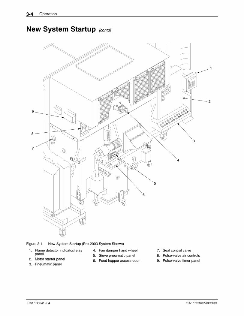
New System Startup (contd)
3
2
1
9
8
5
7
4
6
Figure 3-1 New System Startup (Pre-2003 System Shown)
1. Flame detector indicator/relaypanel
2. Motor starter panel3. Pneumatic panel
4. Fan damper hand wheel5. Sieve pneumatic panel6. Feed hopper access door
7. Seal control valve8. Pulse-valve air controls9. Pulse-valve timer panel
Operation 3-5
Part 106641−04� 2017 Nordson Corporation
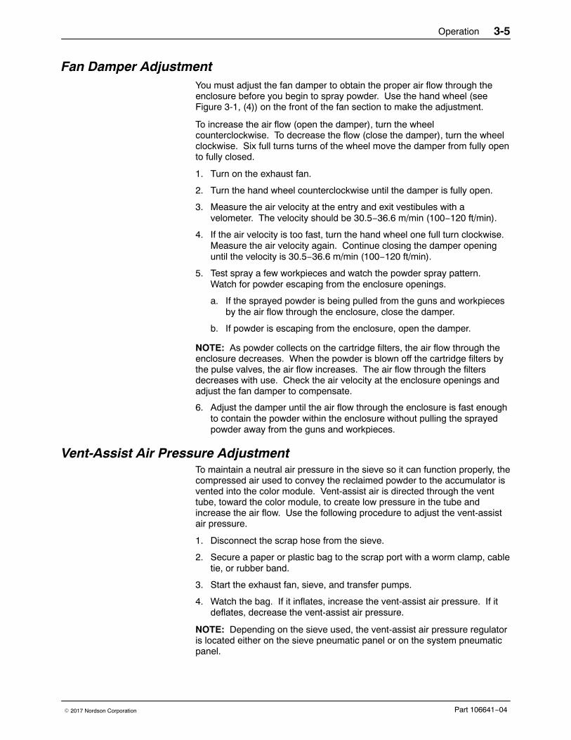
Fan Damper AdjustmentYou must adjust the fan damper to obtain the proper air flow through theenclosure before you begin to spray powder. Use the hand wheel (seeFigure 3-1, (4)) on the front of the fan section to make the adjustment.
To increase the air flow (open the damper), turn the wheelcounterclockwise. To decrease the flow (close the damper), turn the wheelclockwise. Six full turns turns of the wheel move the damper from fully opento fully closed.
1. Turn on the exhaust fan.
2. Turn the hand wheel counterclockwise until the damper is fully open.
3. Measure the air velocity at the entry and exit vestibules with avelometer. The velocity should be 30.5−36.6 m/min (100−120 ft/min).
4. If the air velocity is too fast, turn the hand wheel one full turn clockwise.Measure the air velocity again. Continue closing the damper openinguntil the velocity is 30.5−36.6 m/min (100−120 ft/min).
5. Test spray a few workpieces and watch the powder spray pattern.Watch for powder escaping from the enclosure openings.
a. If the sprayed powder is being pulled from the guns and workpiecesby the air flow through the enclosure, close the damper.
b. If powder is escaping from the enclosure, open the damper.
NOTE: As powder collects on the cartridge filters, the air flow through theenclosure decreases. When the powder is blown off the cartridge filters bythe pulse valves, the air flow increases. The air flow through the filtersdecreases with use. Check the air velocity at the enclosure openings andadjust the fan damper to compensate.
6. Adjust the damper until the air flow through the enclosure is fast enoughto contain the powder within the enclosure without pulling the sprayedpowder away from the guns and workpieces.
Vent-Assist Air Pressure AdjustmentTo maintain a neutral air pressure in the sieve so it can function properly, thecompressed air used to convey the reclaimed powder to the accumulator isvented into the color module. Vent-assist air is directed through the venttube, toward the color module, to create low pressure in the tube andincrease the air flow. Use the following procedure to adjust the vent-assistair pressure.
1. Disconnect the scrap hose from the sieve.
2. Secure a paper or plastic bag to the scrap port with a worm clamp, cabletie, or rubber band.
3. Start the exhaust fan, sieve, and transfer pumps.
4. Watch the bag. If it inflates, increase the vent-assist air pressure. If itdeflates, decrease the vent-assist air pressure.
NOTE: Depending on the sieve used, the vent-assist air pressure regulatoris located either on the sieve pneumatic panel or on the system pneumaticpanel.
Operation3-6
Part 106641−04 � 2017 Nordson Corporation
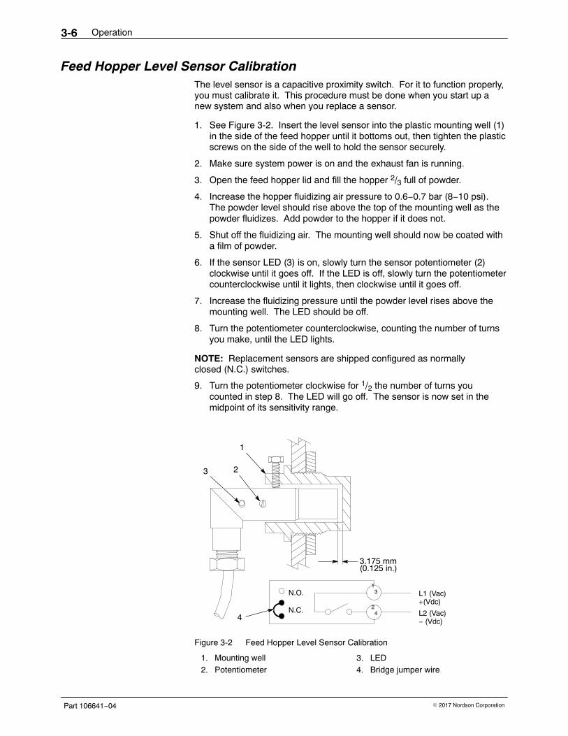
Feed Hopper Level Sensor Calibration The level sensor is a capacitive proximity switch. For it to function properly,you must calibrate it. This procedure must be done when you start up anew system and also when you replace a sensor.
1. See Figure 3-2. Insert the level sensor into the plastic mounting well (1)in the side of the feed hopper until it bottoms out, then tighten the plasticscrews on the side of the well to hold the sensor securely.
2. Make sure system power is on and the exhaust fan is running.
3. Open the feed hopper lid and fill the hopper 2/3 full of powder.
4. Increase the hopper fluidizing air pressure to 0.6−0.7 bar (8−10 psi).The powder level should rise above the top of the mounting well as thepowder fluidizes. Add powder to the hopper if it does not.
5. Shut off the fluidizing air. The mounting well should now be coated witha film of powder.
6. If the sensor LED (3) is on, slowly turn the sensor potentiometer (2)clockwise until it goes off. If the LED is off, slowly turn the potentiometercounterclockwise until it lights, then clockwise until it goes off.
7. Increase the fluidizing pressure until the powder level rises above themounting well. The LED should be off.
8. Turn the potentiometer counterclockwise, counting the number of turnsyou make, until the LED lights.
NOTE: Replacement sensors are shipped configured as normallyclosed (N.C.) switches.
9. Turn the potentiometer clockwise for 1/2 the number of turns youcounted in step 8. The LED will go off. The sensor is now set in themidpoint of its sensitivity range.
1
23
3.175 mm
N.O.
N.C.
L1 (Vac)+(Vdc)
1 3
2 4 L2 (Vac)
− (Vdc)4
(0.125 in.)
Figure 3-2 Feed Hopper Level Sensor Calibration
1. Mounting well2. Potentiometer
3. LED4. Bridge jumper wire
Operation 3-7
Part 106641−04� 2017 Nordson Corporation
Daily Startup and Shutdown ProceduresUse these procedures for routine operation of your system.
Startup1. Turn on the system electrical power and compressed air supply.
2. Inflate the pneumatic seal between the color module and the fansection. Make sure it is sealing correctly.
3. Turn on the exhaust fan at the electrical panel.
4. Walk around the booth. Make sure the application equipment powerand air is on. Make sure the transfer and feed hoses are connected tothe pumps, accumulators, and spray guns.
5. Check all equipment ground connections.
6. Make sure the flame detector system is functioning correctly.
7. Turn on the automatic-gun master control unit and the manual-guncontrol units.
8. Adjust the kV settings and the powder-pump air pressures, if necessary.Refer to your spray gun and control unit manuals.
9. Start the conveyor and start spraying workpieces.
10. Measure the air flow velocity at the vestibules with a velometer. Thevelocity should be 30.5−36.6 m/min (100−120 ft/min). Make sure thesprayed powder is not being pulled from the spray guns and workpieces,and that the powder is not escaping from the enclosure openings.Adjust the fan damper as needed to maintain the proper air flow.
Shutdown1. Start the transfer pumps and sieves. Pump the reclaimed powder from
the color module hoppers back into the feed hopper.
2. Turn off the automatic-gun master control unit and the manual-guncontrol units.
3. Perform the daily maintenance procedures described in theMaintenance section. Clean the powder pumps and spray guns asdescribed in their manuals. Perform daily maintenance procedures forother system equipment, as described in their manuals.
4. Turn off the exhaust fan. Shut off the system electrical power andcompressed air supply.
Operation3-8
Part 106641−04 � 2017 Nordson Corporation
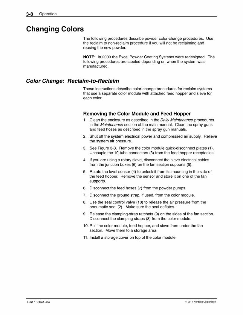
Changing ColorsThe following procedures describe powder color-change procedures. Usethe reclaim to non-reclaim procedure if you will not be reclaiming andreusing the new powder.
NOTE: In 2003 the Excel Powder Coating Systems were redesigned. Thefollowing procedures are labeled depending on when the system wasmanufactured.
Color Change: Reclaim-to-Reclaim These instructions describe color-change procedures for reclaim systemsthat use a separate color module with attached feed hopper and sieve foreach color.
Removing the Color Module and Feed Hopper 1. Clean the enclosure as described in the Daily Maintenance procedures
in the Maintenance section of the main manual. Clean the spray gunsand feed hoses as described in the spray gun manuals.
2. Shut off the system electrical power and compressed air supply. Relievethe system air pressure.
3. See Figure 3-3. Remove the color module quick-disconnect plates (1).Uncouple the 10-tube connectors (3) from the feed hopper receptacles.
4. If you are using a rotary sieve, disconnect the sieve electrical cablesfrom the junction boxes (6) on the fan section supports (5).
5. Rotate the level sensor (4) to unlock it from its mounting in the side ofthe feed hopper. Remove the sensor and store it on one of the fansupports.
6. Disconnect the feed hoses (7) from the powder pumps.
7. Disconnect the ground strap, if used, from the color module.
8. Use the seal control valve (10) to release the air pressure from thepneumatic seal (2). Make sure the seal deflates.
9. Release the clamping-strap ratchets (9) on the sides of the fan section.Disconnect the clamping straps (8) from the color module.
10. Roll the color module, feed hopper, and sieve from under the fansection. Move them to a storage area.
11. Install a storage cover on top of the color module.
Operation 3-9
Part 106641−04� 2017 Nordson Corporation
10
9
8
6
1
2
7
5
4
3
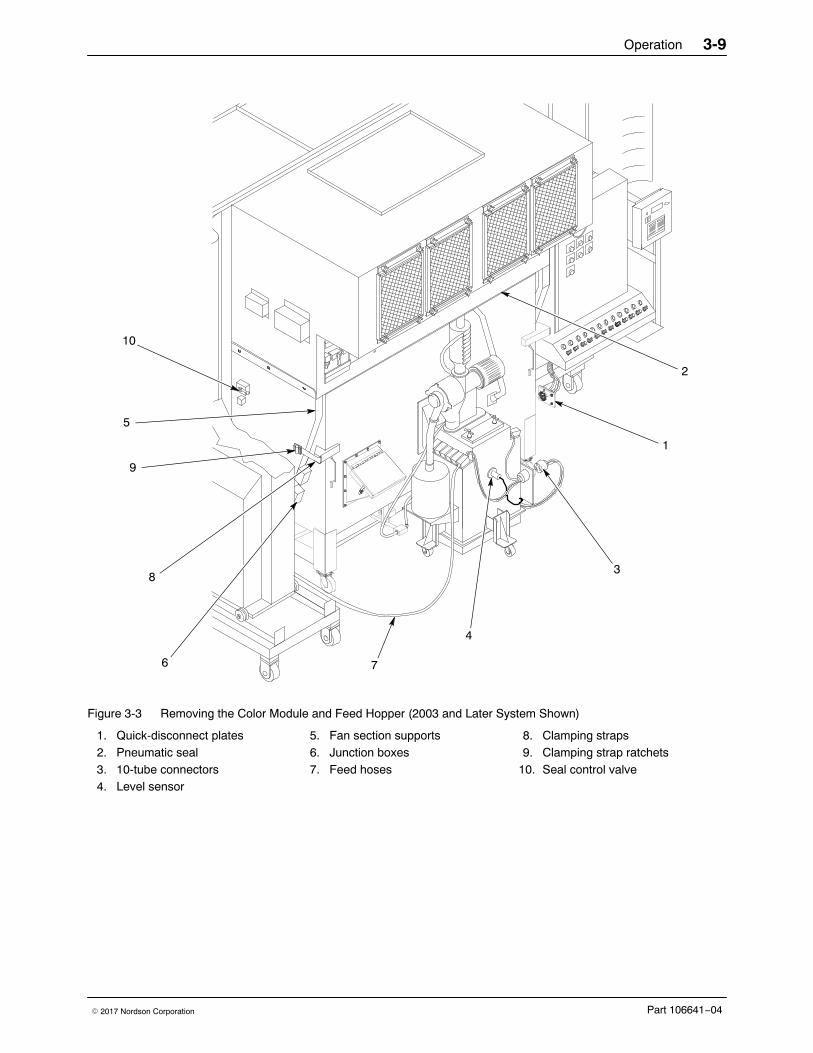
Figure 3-3 Removing the Color Module and Feed Hopper (2003 and Later System Shown)
1. Quick-disconnect plates2. Pneumatic seal3. 10-tube connectors4. Level sensor
5. Fan section supports6. Junction boxes7. Feed hoses
8. Clamping straps9. Clamping strap ratchets
10. Seal control valve
Operation3-10
Part 106641−04 � 2017 Nordson Corporation
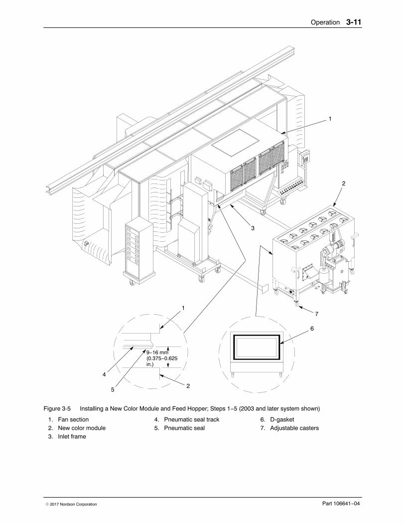
Installing a New Color Module and Feed Hopper 1. See Figure 3-5. Thoroughly clean the powder off the inlet frame (3) and
surrounding area.
NOTE: If you find large amounts of powder in the fan and pulse valvecompartments, the cartridge filters are leaking. Fix the problem beforeproceeding. Refer to the Troubleshooting and Repair sections in themain manual for instructions.
2. Inspect and clean the interior of the fan section (1). Check thepneumatic seal (5), and replace it if it is damaged.
3. Remove the storage cover from the new color module (2). Inspect themodule D-gasket (6) and replace it if it is damaged.
4. Position the new color module under the fan section, against the inletframe stops.
NOTE: If the limit switch is not closed, you will not be able to start thesystem. Adjust the limit switch position as necessary by loosening themounting screws and sliding the switch forward or back.
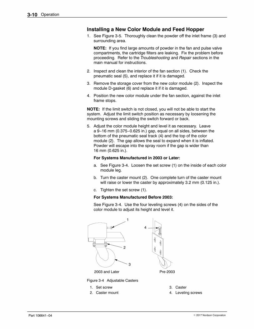
5. Adjust the color module height and level it as necessary. Leavea 9−16 mm (0.375−0.625 in.) gap, equal on all sides, between thebottom of the pneumatic seal track (4) and the top of the colormodule (2). The gap allows the seal to expand when it is inflated.Powder will escape into the spray room if the gap is wider than16 mm (0.625 in.).
For Systems Manufactured in 2003 or Later:
a. See Figure 3-4. Loosen the set screw (1) on the inside of each colormodule leg.
b. Turn the caster mount (2). One complete turn of the caster mountwill raise or lower the caster by approximately 3.2 mm (0.125 in.).
c. Tighten the set screw (1).
For Systems Manufactured Before 2003:
See Figure 3-4. Use the four leveling screws (4) on the sides of thecolor module to adjust its height and level it.
3
1
2
2003 and Later Pre-2003
4
Figure 3-4 Adjustable Casters
1. Set screw2. Caster mount
3. Caster4. Leveling screws
Operation 3-11
Part 106641−04� 2017 Nordson Corporation
9−16 mm(0.375−0.625in.)
3
1
6
7
2
4
52
1
Figure 3-5 Installing a New Color Module and Feed Hopper; Steps 1−5 (2003 and later system shown)
1. Fan section2. New color module3. Inlet frame
4. Pneumatic seal track5. Pneumatic seal
6. D-gasket7. Adjustable casters
Operation3-12
Part 106641−04 � 2017 Nordson Corporation
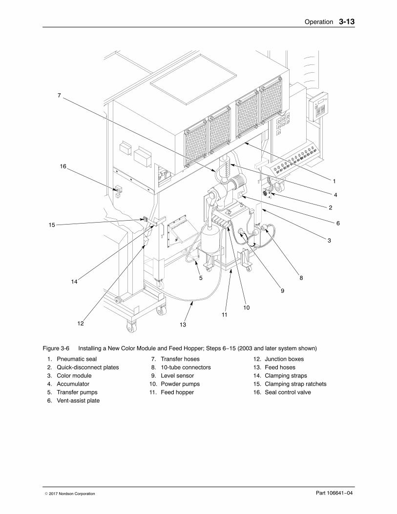
Installing a New Color Module and Feed Hopper (contd)
6. See Figure 3-5. Hook the clamping straps (14) to the color module (3).Tighten the ratchets (15) to pull the color module against the stops andcompress the D-gasket against the inlet frame. This must also close thelimit switch on the inlet frame.
7. Use the seal control valve (16) to inflate the pneumatic seal (1). Makesure it is sealing on all four sides of the color module.
8. Connect the quick-disconnect plates (2) to the color module.
9. Connect the 10-tube connectors (8) to the receptacles on the feedhopper.
10. Install the level sensor (9) into the mounting on the feed hopper.
11. Make sure the accumulator (4) vent hose is connected to the vent-assistplate (6), and that the vent-assist air tubing is connected to the tubefitting.
12. Connect the sieve electrical cables to the junction boxes (12) on the fansection support.
13. Disconnect the old feed hoses (13) from the guns. Install new feedhoses between the powder pumps (10) and the guns, or use hoses thathave already been used with the new color.
14. Make sure the transfer hoses (7) are connected to the accumulator andtransfer pumps (5).
15. Connect all equipment ground straps and wiring.
16. Perform the Startup after Color Change procedures on page 3-15.
Operation 3-13
Part 106641−04� 2017 Nordson Corporation
16
7
14
12
2
1
13
15
9
8
4
6
1011
5
3
Figure 3-6 Installing a New Color Module and Feed Hopper; Steps 6−15 (2003 and later system shown)
1. Pneumatic seal2. Quick-disconnect plates3. Color module4. Accumulator5. Transfer pumps6. Vent-assist plate
7. Transfer hoses8. 10-tube connectors9. Level sensor
10. Powder pumps11. Feed hopper
12. Junction boxes13. Feed hoses14. Clamping straps15. Clamping strap ratchets16. Seal control valve
Operation3-14
Part 106641−04 � 2017 Nordson Corporation
Color Change: Reclaim to Non-ReclaimWhen you change to a powder you will not reclaim, the new powder will becollected in a new color module and pumped by the transfer pumps into ascrap drum. To supply powder to the spray guns, use a feed hopperattached to the color module, or an unattached, portable feed hopper.
Systems designed to use portable feed hoppers for non-reclaimed powdershave a quick-disconnect plate mounted on a fan section support instead ofon the color module. The air tubing for the feed hopper and the the powderpumps are terminated in one or more 10-tube connectors.
New Color Module with Attached Feed Hopper� Complete all the steps under Removing the Color Module and Feed
Hopper on page 3-8.
� Perform steps 1 through 9 under Installing a New Color Module andFeed Hopper on page 3-10.
� Perform steps 4 through 9 under New Color Module with Portable FeedHopper on page 3-14.
NOTE: If the attached feed hopper is equipped with a sieve, accumulator,and level sensor, plug the ports in the accumulator after disconnecting thetransfer hoses (see Figure 3-6, item 7). Plug the level sensor mountinghole.
New Color Module with Portable Feed Hopper � Complete all the steps under Removing Color Module and Feed Hopper
on page 3-8.
� Perform steps 1 through 8 under Installing a New Color Module andFeed Hopper on page 3-10.
� Perform the following steps.
1. Block the feed-hopper vent port in the color module with a gasketedcover plate.
2. See Figure 3-6. Position the portable feed hopper so the feedhoses (13) from the powder pumps can be connected to the guns.
3. Install a vent hose between the vent on the feed hopper lid and thevent-assist plate (6) on the color module. Clamp the hose to the hoppervent and the vent-assist plate.
4. Connect air tubing to the tubing connector on the vent-assist plate.
5. Connect the 10-tube connectors to the receptacles on the fan sectionsupport.
6. Install new feed hoses (13) between the pumps and the guns. Usehoses that have already been used with the new color, if possible.
7. Install a scrap drum lid on a 55-gallon drum.
8. Connect the transfer hoses (7) from the transfer pumps (5) to the scrapdrum lid.
Operation 3-15
Part 106641−04� 2017 Nordson Corporation
9. Connect the portable feed-hopper ground strap to a ground connection,such as the booth base. Make sure all other equipment ground strapsare connected.
10. Set the transfer-pump selector switch to MANUAL or OFF.
a. Set the switch to MANUAL to continuously pump the collectedpowder from the color module to the scrap drum.
b. Set the switch to OFF if you want to wait until you are done sprayingbefore you pump the powder into the scrap drum.
11. Perform the Startup after Color Change procedure.
Startup after Color Change Before starting the system, make sure all tubing, hoses, electrical cables,and ground straps have been reconnected.
1. Turn on the system electrical power and compressed air supply.
2. Rotate the seal control valve to inflate the seal. Make sure the seal ispressing against the color module equally on all four sides. Adjust theheight of the color module and level it to correct any sealing problems.
3. Start the exhaust fan.
4. Fill the feed hopper 2/3 full of powder. Adjust the hopper fluidizing-airregulator until the powder boils gently. Wait 5−10 minutes for thepowder to fluidize.
5. Start spraying parts.
6. Adjust the powder-pump air pressures and gun voltages, if necessary.(Different colors or powders may require different settings.)
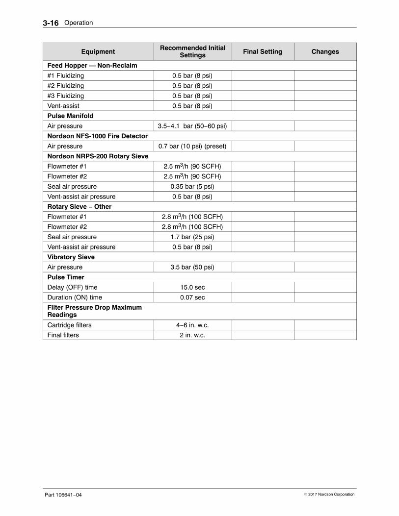
Equipment Recommended InitialSettings Final Setting Changes
Primary Air Pressure (plant air) 5.5 bar (80 psi)
Collector Module
#1 Fluidizing 0.7 bar (10 psi)
#2 Fluidizing 0.7 bar (10 psi)
#3 Fluidizing (pre-2003) 0.7 bar (10 psi)
#4 Fluidizing (pre-2003) 0.7 bar (10 psi)
#1 Transfer pump 1.7 bar (25 psi)
#2 Transfer pump 1.7 bar (25 psi)
#3 Transfer pump (pre-2003) 1.7 bar (25 psi)
#4 Transfer pump (pre-2003) 1.7 bar (25 psi)
Feed Hopper — Reclaim
Fluidizing 0.5 bar (8 psi)
Vent-assist 2.8 bar (40 psi)
Continued...
Operation3-16
Part 106641−04 � 2017 Nordson Corporation
ChangesFinal SettingRecommended InitialSettingsEquipment
Feed Hopper — Non-Reclaim
#1 Fluidizing 0.5 bar (8 psi)
#2 Fluidizing 0.5 bar (8 psi)
#3 Fluidizing 0.5 bar (8 psi)
Vent-assist 0.5 bar (8 psi)
Pulse Manifold
Air pressure 3.5−4.1 bar (50−60 psi)
Nordson NFS-1000 Fire Detector
Air pressure 0.7 bar (10 psi) (preset)
Nordson NRPS-200 Rotary Sieve
Flowmeter #1 2.5 m3/h (90 SCFH)
Flowmeter #2 2.5 m3/h (90 SCFH)
Seal air pressure 0.35 bar (5 psi)
Vent-assist air pressure 0.5 bar (8 psi)
Rotary Sieve − Other
Flowmeter #1 2.8 m3/h (100 SCFH)
Flowmeter #2 2.8 m3/h (100 SCFH)
Seal air pressure 1.7 bar (25 psi)
Vent-assist air pressure 0.5 bar (8 psi)
Vibratory Sieve
Air pressure 3.5 bar (50 psi)
Pulse Timer
Delay (OFF) time 15.0 sec
Duration (ON) time 0.07 sec
Filter Pressure Drop MaximumReadings
Cartridge filters 4−6 in. w.c.
Final filters 2 in. w.c.
Maintenance 4-1
Part 106641−04� 2017 Nordson Corporation
Section 4Maintenance
WARNING: Allow only qualified personnel to perform the following tasks.Follow the safety instructions in this document and all other relateddocumentation.
Daily MaintenancePerform these procedures daily to keep your system clean and functioningproperly.
CleaningPerform this procedure daily and when changing powder color or type.
WARNING: Wear an approved respirator and safety glasses or goggleswhen handling powder, operating spray equipment, or performingmaintenance or cleaning operations. Obtain and read Material Safety DataSheets for each powder used.
1. Turn off the automatic-gun master-control unit(s) and manual-guncontrol units.
2. Turn on the exhaust fan.
3. Disconnect the powder-feed hoses from the powder pumps. Blow thepowder out of the hoses and spray guns with compressed air.
4. Ground the gun electrodes and clean the spray guns according to theinstructions in the gun manuals.
5. Clean the enclosure roof, walls, and floor with a rubber squeegee. Pushthe collected powder into the color module.
6. Remove the remaining powder residue from the enclosure with anair-powered vacuum and a soft brush attachment. Wipe down allsurfaces with a damp, lint-free cloth (do not use tack cloths). If youremove the color module, clean the inlet frame and surrounding area.
7. Turn off the exhaust fan.
8. Clean the operator’s platform and the floor around the booth.
Maintenance4-2
Part 106641−04 � 2017 Nordson Corporation
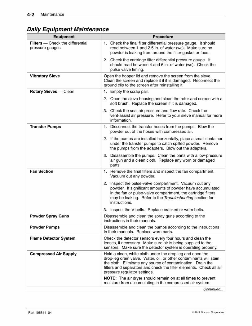
Daily Equipment MaintenanceEquipment Procedure
Filters — Check the differentialpressure gauges.
1. Check the final filter differential pressure gauge. It shouldread between 1 and 2.5 in. of water (wc). Make sure nopowder is leaking from around the filter gasket or face.
2. Check the cartridge filter differential pressure gauge. Itshould read between 4 and 6 in. of water (wc). Check thepulse valve timing.
Vibratory Sieve Open the hopper lid and remove the screen from the sieve.Clean the screen and replace it if it is damaged. Reconnect theground clip to the screen after reinstalling it.
Rotary Sieves — Clean 1. Empty the scrap pail.
2. Open the sieve housing and clean the rotor and screen with asoft brush. Replace the screen if it is damaged.
3. Check the seal air pressure and flow rate. Check thevent-assist air pressure. Refer to your sieve manual for moreinformation.
Transfer Pumps 1. Disconnect the transfer hoses from the pumps. Blow thepowder out of the hoses with compressed air.
2. If the pumps are installed horizontally, place a small containerunder the transfer pumps to catch spilled powder. Removethe pumps from the adapters. Blow out the adapters.
3. Disassemble the pumps. Clean the parts with a low-pressureair gun and a clean cloth. Replace any worn or damagedparts.
Fan Section 1. Remove the final filters and inspect the fan compartment.Vacuum out any powder.
2. Inspect the pulse-valve compartment. Vacuum out anypowder. If significant amounts of powder have accumulatedin the fan or pulse-valve compartment, the cartridge filtersmay be leaking. Refer to the Troubleshooting section forinstructions.
3. Inspect the V-belts. Replace cracked or worn belts.
Powder Spray Guns Disassemble and clean the spray guns according to theinstructions in their manuals.
Powder Pumps Disassemble and clean the pumps according to the instructionsin their manuals. Replace worn parts.
Flame Detector System Check the detector sensors every four hours and clean thelenses, if necessary. Make sure air is being supplied to thesensors. Make sure the detector system is operating properly.
Compressed Air Supply Hold a clean, white cloth under the drop leg and open thedrop-leg drain valve. Water, oil, or other contaminants will stainthe cloth. Eliminate any source of contamination. Drain thefilters and separators and check the filter elements. Check all airpressure regulator settings.
NOTE: The air dryer should remain on at all times to preventmoisture from accumulating in the compressed air system.
Continued...
Maintenance 4-3
Part 106641−04� 2017 Nordson Corporation
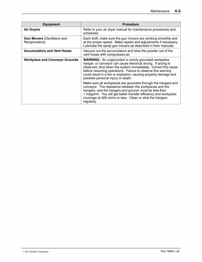
Equipment Procedure
Air Dryers Refer to your air dryer manual for maintenance procedures andschedules.
Gun Movers (Oscillators andReciprocators)
Each shift, make sure the gun movers are stroking smoothly andat the proper speed. Make repairs and adjustments if necessary.Lubricate the spray gun movers as described in their manuals.
Accumulators and Vent Hoses Vacuum out the accumulators and blow the powder out of thevent hoses with compressed air.
Workpiece and Conveyor Grounds WARNING: An ungrounded or poorly grounded workpiece,hanger, or conveyor can cause electrical arcing. If arcing isobserved, shut down the system immediately. Correct the causebefore resuming operations. Failure to observe this warningcould result in a fire or explosion, causing property damage andpossible personal injury or death.
Make sure all workpieces are grounded through the hangers andconveyor. The resistance between the workpieces and thehangers, and the hangers and ground, must be less than1 megohm. You will get better transfer efficiency and workpiececoverage at 500 ohms or less. Clean or strip the hangersregularly.
Maintenance4-4
Part 106641−04 � 2017 Nordson Corporation
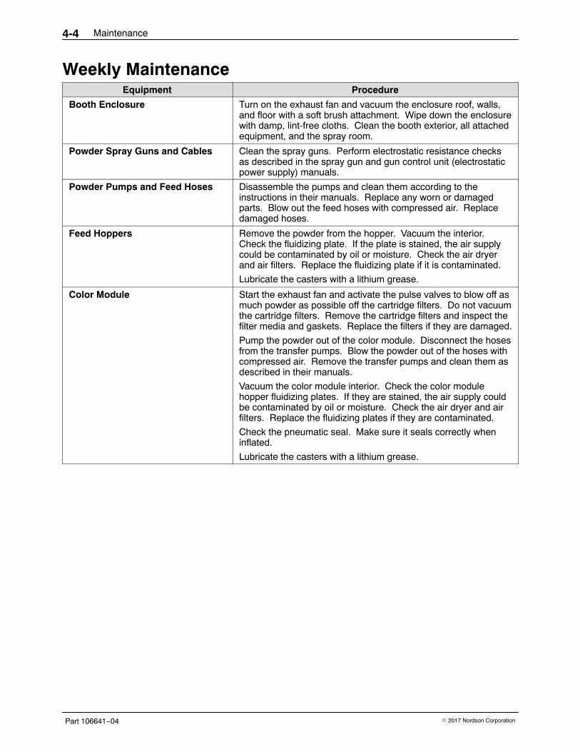
Weekly MaintenanceEquipment Procedure
Booth Enclosure Turn on the exhaust fan and vacuum the enclosure roof, walls,and floor with a soft brush attachment. Wipe down the enclosurewith damp, lint-free cloths. Clean the booth exterior, all attachedequipment, and the spray room.
Powder Spray Guns and Cables Clean the spray guns. Perform electrostatic resistance checksas described in the spray gun and gun control unit (electrostaticpower supply) manuals.
Powder Pumps and Feed Hoses Disassemble the pumps and clean them according to theinstructions in their manuals. Replace any worn or damagedparts. Blow out the feed hoses with compressed air. Replacedamaged hoses.
Feed Hoppers Remove the powder from the hopper. Vacuum the interior.Check the fluidizing plate. If the plate is stained, the air supplycould be contaminated by oil or moisture. Check the air dryerand air filters. Replace the fluidizing plate if it is contaminated.
Lubricate the casters with a lithium grease.
Color Module Start the exhaust fan and activate the pulse valves to blow off asmuch powder as possible off the cartridge filters. Do not vacuumthe cartridge filters. Remove the cartridge filters and inspect thefilter media and gaskets. Replace the filters if they are damaged.
Pump the powder out of the color module. Disconnect the hosesfrom the transfer pumps. Blow the powder out of the hoses withcompressed air. Remove the transfer pumps and clean them asdescribed in their manuals.
Vacuum the color module interior. Check the color modulehopper fluidizing plates. If they are stained, the air supply couldbe contaminated by oil or moisture. Check the air dryer and airfilters. Replace the fluidizing plates if they are contaminated.
Check the pneumatic seal. Make sure it seals correctly wheninflated.
Lubricate the casters with a lithium grease.
Maintenance 4-5
Part 106641−04� 2017 Nordson Corporation
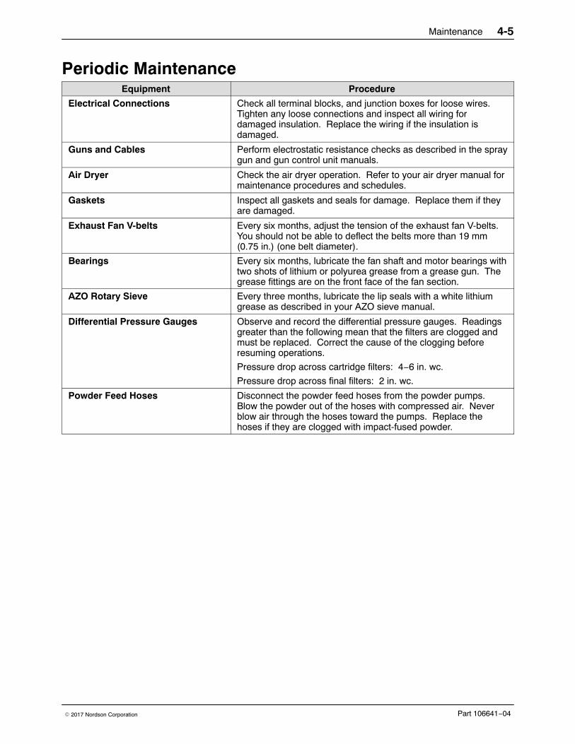
Periodic MaintenanceEquipment Procedure
Electrical Connections Check all terminal blocks, and junction boxes for loose wires.Tighten any loose connections and inspect all wiring fordamaged insulation. Replace the wiring if the insulation isdamaged.
Guns and Cables Perform electrostatic resistance checks as described in the spraygun and gun control unit manuals.
Air Dryer Check the air dryer operation. Refer to your air dryer manual formaintenance procedures and schedules.
Gaskets Inspect all gaskets and seals for damage. Replace them if theyare damaged.
Exhaust Fan V-belts Every six months, adjust the tension of the exhaust fan V-belts.You should not be able to deflect the belts more than 19 mm(0.75 in.) (one belt diameter).
Bearings Every six months, lubricate the fan shaft and motor bearings withtwo shots of lithium or polyurea grease from a grease gun. Thegrease fittings are on the front face of the fan section.
AZO Rotary Sieve Every three months, lubricate the lip seals with a white lithiumgrease as described in your AZO sieve manual.
Differential Pressure Gauges Observe and record the differential pressure gauges. Readingsgreater than the following mean that the filters are clogged andmust be replaced. Correct the cause of the clogging beforeresuming operations.
Pressure drop across cartridge filters: 4−6 in. wc.
Pressure drop across final filters: 2 in. wc.
Powder Feed Hoses Disconnect the powder feed hoses from the powder pumps.Blow the powder out of the hoses with compressed air. Neverblow air through the hoses toward the pumps. Replace thehoses if they are clogged with impact-fused powder.
Maintenance4-6
Part 106641−04 � 2017 Nordson Corporation
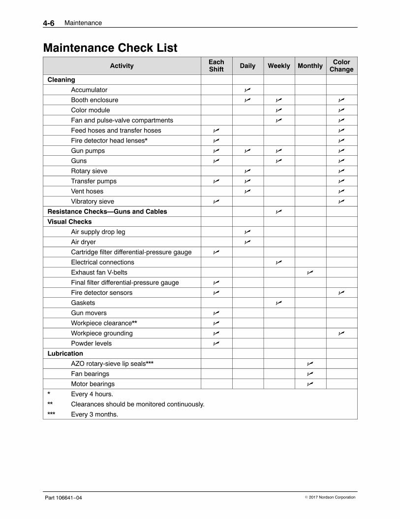
Maintenance Check ListActivity Each
Shift Daily Weekly Monthly ColorChange
Cleaning
Accumulator �
Booth enclosure � � �
Color module � �
Fan and pulse-valve compartments � �
Feed hoses and transfer hoses � �
Fire detector head lenses* � �
Gun pumps � � � �
Guns � � �
Rotary sieve � �
Transfer pumps � � �
Vent hoses � �
Vibratory sieve � �
Resistance Checks—Guns and Cables �
Visual Checks
Air supply drop leg �
Air dryer �
Cartridge filter differential-pressure gauge �
Electrical connections �
Exhaust fan V-belts �
Final filter differential-pressure gauge �
Fire detector sensors � �
Gaskets �
Gun movers �
Workpiece clearance** �
Workpiece grounding � �
Powder levels �
Lubrication
AZO rotary-sieve lip seals*** �
Fan bearings �
Motor bearings �
* Every 4 hours.
** Clearances should be monitored continuously.
*** Every 3 months.
Troubleshooting 5-1
Part 106641−04� 2017 Nordson Corporation
Section 5Troubleshooting
WARNING: Allow only qualified personnel to perform the following tasks.Follow the safety instructions in this document and all other relateddocumentation.
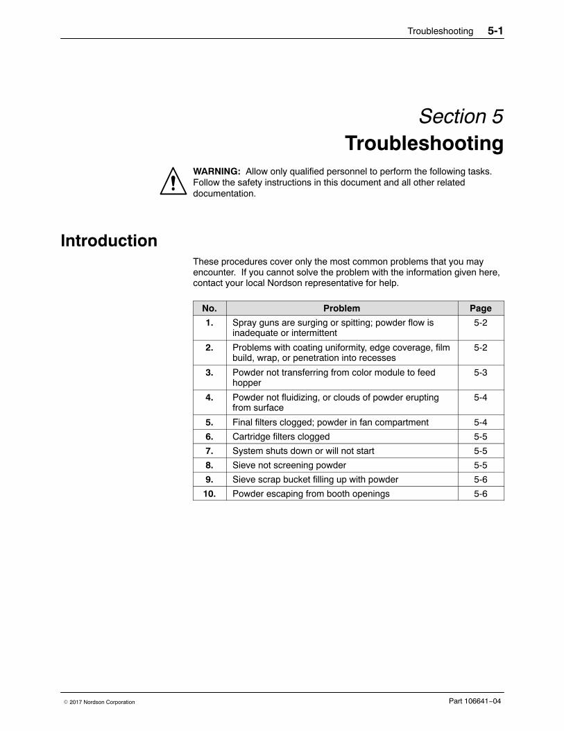
Introduction These procedures cover only the most common problems that you mayencounter. If you cannot solve the problem with the information given here,contact your local Nordson representative for help.
No. Problem Page
1. Spray guns are surging or spitting; powder flow isinadequate or intermittent
5-2
2. Problems with coating uniformity, edge coverage, filmbuild, wrap, or penetration into recesses
5-2
3. Powder not transferring from color module to feedhopper
5-3
4. Powder not fluidizing, or clouds of powder eruptingfrom surface
5-4
5. Final filters clogged; powder in fan compartment 5-4
6. Cartridge filters clogged 5-5
7. System shuts down or will not start 5-5
8. Sieve not screening powder 5-5
9. Sieve scrap bucket filling up with powder 5-6
10. Powder escaping from booth openings 5-6
Troubleshooting5-2
Part 106641−04 � 2017 Nordson Corporation
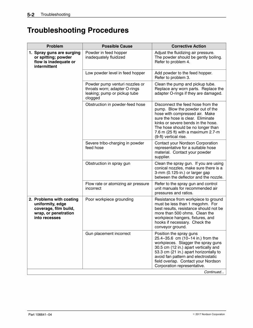
Troubleshooting Procedures
Problem Possible Cause Corrective Action
1. Spray guns are surgingor spitting; powderflow is inadequate orintermittent
Powder in feed hopperinadequately fluidized
Adjust the fluidizing air pressure.The powder should be gently boiling.Refer to problem 4.
Low powder level in feed hopper Add powder to the feed hopper.Refer to problem 3.
Powder pump venturi nozzles orthroats worn; adapter O-ringsleaking; pump or pickup tubeclogged
Clean the pump and pickup tube.Replace any worn parts. Replace theadapter O-rings if they are damaged.
Obstruction in powder-feed hose Disconnect the feed hose from thepump. Blow the powder out of thehose with compressed air. Makesure the hose is clear. Eliminatekinks or severe bends in the hose.The hose should be no longer than7.6 m (25 ft) with a maximum 2.7-m(9-ft) vertical rise.
Severe tribo-charging in powderfeed hose
Contact your Nordson Corporationrepresentative for a suitable hosematerial. Contact your powdersupplier.
Obstruction in spray gun Clean the spray gun. If you are usingconical nozzles, make sure there is a3-mm (0.125-in.) or larger gapbetween the deflector and the nozzle.
Flow rate or atomizing air pressureincorrect
Refer to the spray gun and controlunit manuals for recommended airpressures and ratios.
2. Problems with coatinguniformity, edgecoverage, film build,wrap, or penetrationinto recesses
Poor workpiece grounding Resistance from workpiece to groundmust be less than 1 megohm. Forbest results, resistance should not bemore than 500 ohms. Clean theworkpiece hangers, fixtures, andhooks if necessary. Check theconveyor ground.
Gun placement incorrect Position the spray guns25.4−35.6 cm (10−14 in.) from theworkpieces. Stagger the spray guns30.5 cm (12 in.) apart vertically and53.3 cm (21 in.) apart horizontally toavoid fan pattern and electrostaticfield overlap. Contact your NordsonCorporation representative.
Continued...
Troubleshooting 5-3
Part 106641−04� 2017 Nordson Corporation
Problem Possible Cause Corrective Action
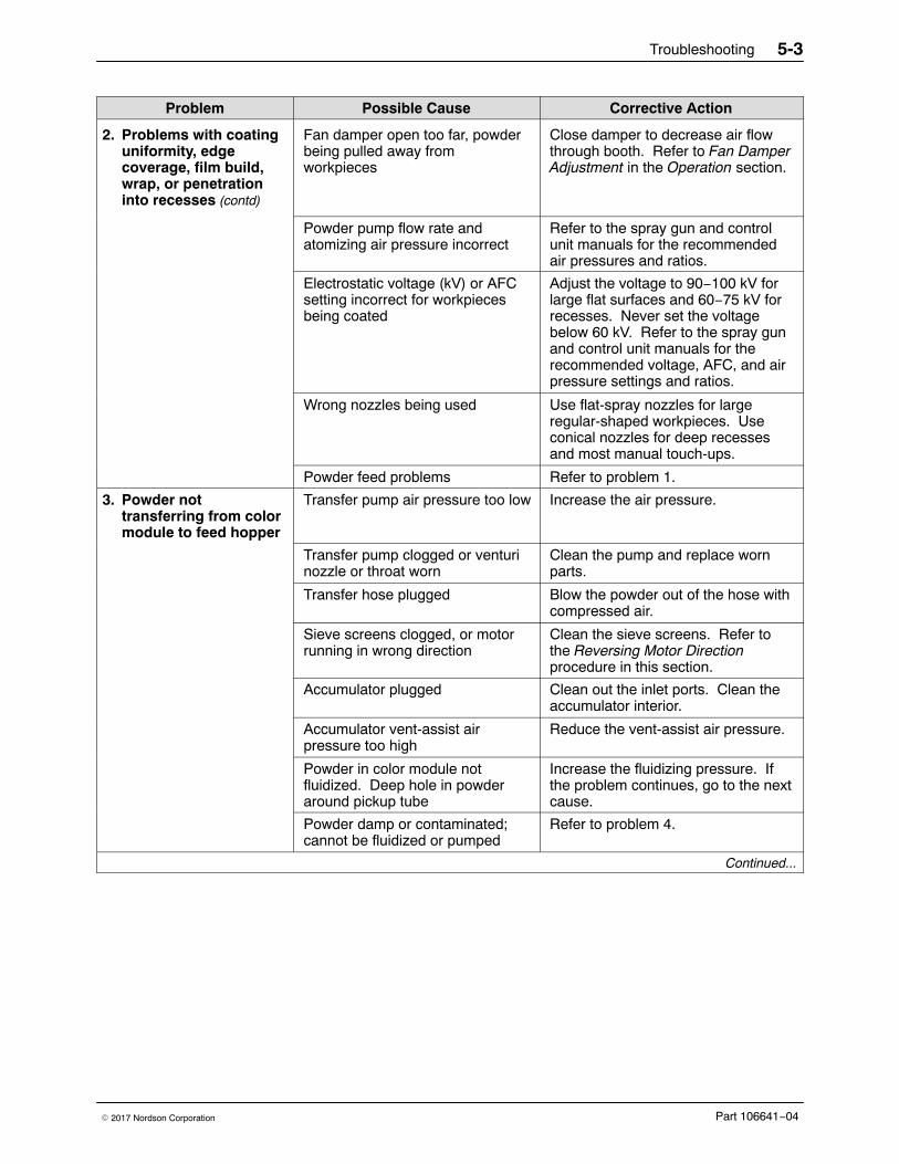
2. Problems with coatinguniformity, edgecoverage, film build,wrap, or penetrationinto recesses (contd)
Fan damper open too far, powderbeing pulled away fromworkpieces
Close damper to decrease air flowthrough booth. Refer to Fan DamperAdjustment in the Operation section.
Powder pump flow rate andatomizing air pressure incorrect
Refer to the spray gun and controlunit manuals for the recommendedair pressures and ratios.
Electrostatic voltage (kV) or AFCsetting incorrect for workpiecesbeing coated
Adjust the voltage to 90−100 kV forlarge flat surfaces and 60−75 kV forrecesses. Never set the voltagebelow 60 kV. Refer to the spray gunand control unit manuals for therecommended voltage, AFC, and airpressure settings and ratios.
Wrong nozzles being used Use flat-spray nozzles for largeregular-shaped workpieces. Useconical nozzles for deep recessesand most manual touch-ups.
Powder feed problems Refer to problem 1.
3. Powder nottransferring from colormodule to feed hopper
Transfer pump air pressure too low Increase the air pressure.
Transfer pump clogged or venturinozzle or throat worn
Clean the pump and replace wornparts.
Transfer hose plugged Blow the powder out of the hose withcompressed air.
Sieve screens clogged, or motorrunning in wrong direction
Clean the sieve screens. Refer tothe Reversing Motor Directionprocedure in this section.
Accumulator plugged Clean out the inlet ports. Clean theaccumulator interior.
Accumulator vent-assist airpressure too high
Reduce the vent-assist air pressure.
Powder in color module notfluidized. Deep hole in powderaround pickup tube
Increase the fluidizing pressure. Ifthe problem continues, go to the nextcause.
Powder damp or contaminated;cannot be fluidized or pumped
Refer to problem 4.
Continued...
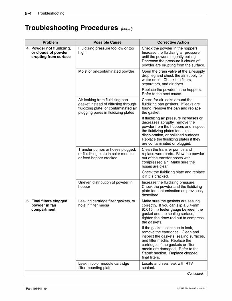
Troubleshooting5-4
Part 106641−04 � 2017 Nordson Corporation
Troubleshooting Procedures (contd)
Problem Possible Cause Corrective Action
4. Powder not fluidizing,or clouds of powdererupting from surface
Fluidizing pressure too low or toohigh
Check the powder in the hoppers.Increase the fluidizing air pressureuntil the powder is gently boiling.Decrease the pressure if clouds ofpowder are erupting from the surface.
Moist or oil-contaminated powder Open the drain valve at the air-supplydrop leg and check the air supply forwater or oil. Check the filters,separators, and air dryer.
Replace the powder in the hoppers.Refer to the next cause.
Air leaking from fluidizing pangasket instead of diffusing throughfluidizing plate, or contaminated airplugging pores in fluidizing plates
Check for air leaks around thefluidizing pan gaskets. If leaks arefound, remove the pan and replacethe gasket.
If fluidizing air pressure increases ordecreases abruptly, remove thepowder from the hoppers and inspectthe fluidizing plates for stains,discoloration, or polished surfaces.Replace the fluidizing plates if theyare contaminated or plugged.
Transfer pumps or hoses plugged,or fluidizing plate in color moduleor feed hopper cracked
Clean the transfer pumps andreplace worn parts. Blow the powderout of the transfer hoses withcompressed air. Make sure thehoses are clear.
Check the fluidizing plate and replaceit if it is cracked.
Uneven distribution of powder inhopper
Increase the fluidizing pressure.Check the powder and the fluidizingplate for contamination as previouslydescribed.
5. Final filters clogged;powder in fancompartment
Leaking cartridge filter gaskets, orhole in filter media
Make sure the gaskets are sealingcorrectly. If you can slip a 0.4-mm(0.015 in.) feeler gauge between thegasket and the sealing surface,tighten the draw-rod nut to compressthe gaskets.
If the gaskets continue to leak,remove the cartridges. Clean andinspect the gaskets, sealing surfaces,and filter media. Replace thecartridges if the gaskets or filtermedia are damaged. Refer to theRepair section. Replace cloggedfinal filters.
Leak in color module cartridgefilter mounting plate
Locate and seal leak with RTVsealant.
Continued...
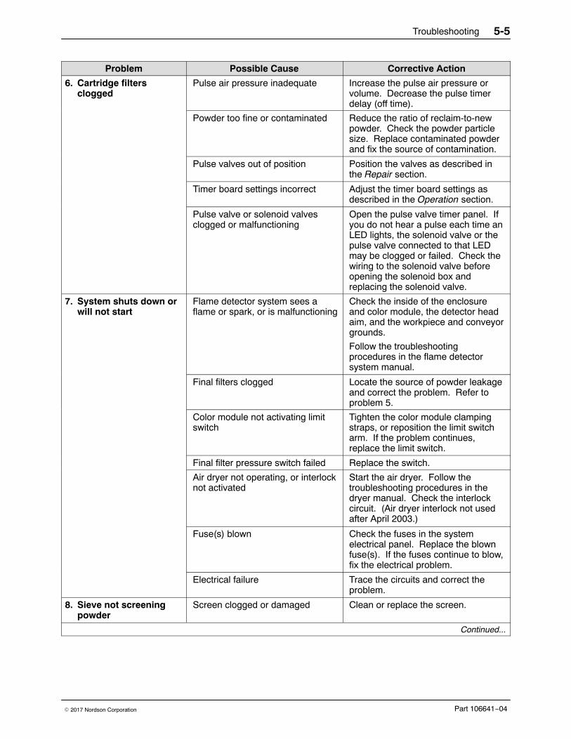
Troubleshooting 5-5
Part 106641−04� 2017 Nordson Corporation
Corrective ActionPossible CauseProblem
6. Cartridge filtersclogged
Pulse air pressure inadequate Increase the pulse air pressure orvolume. Decrease the pulse timerdelay (off time).
Powder too fine or contaminated Reduce the ratio of reclaim-to-newpowder. Check the powder particlesize. Replace contaminated powderand fix the source of contamination.
Pulse valves out of position Position the valves as described inthe Repair section.
Timer board settings incorrect Adjust the timer board settings asdescribed in the Operation section.
Pulse valve or solenoid valvesclogged or malfunctioning
Open the pulse valve timer panel. Ifyou do not hear a pulse each time anLED lights, the solenoid valve or thepulse valve connected to that LEDmay be clogged or failed. Check thewiring to the solenoid valve beforeopening the solenoid box andreplacing the solenoid valve.
7. System shuts down orwill not start
Flame detector system sees aflame or spark, or is malfunctioning
Check the inside of the enclosureand color module, the detector headaim, and the workpiece and conveyorgrounds.
Follow the troubleshootingprocedures in the flame detectorsystem manual.
Final filters clogged Locate the source of powder leakageand correct the problem. Refer toproblem 5.
Color module not activating limitswitch
Tighten the color module clampingstraps, or reposition the limit switcharm. If the problem continues,replace the limit switch.
Final filter pressure switch failed Replace the switch.
Air dryer not operating, or interlocknot activated
Start the air dryer. Follow thetroubleshooting procedures in thedryer manual. Check the interlockcircuit. (Air dryer interlock not usedafter April 2003.)
Fuse(s) blown Check the fuses in the systemelectrical panel. Replace the blownfuse(s). If the fuses continue to blow,fix the electrical problem.
Electrical failure Trace the circuits and correct theproblem.
8. Sieve not screeningpowder
Screen clogged or damaged Clean or replace the screen.
Continued...
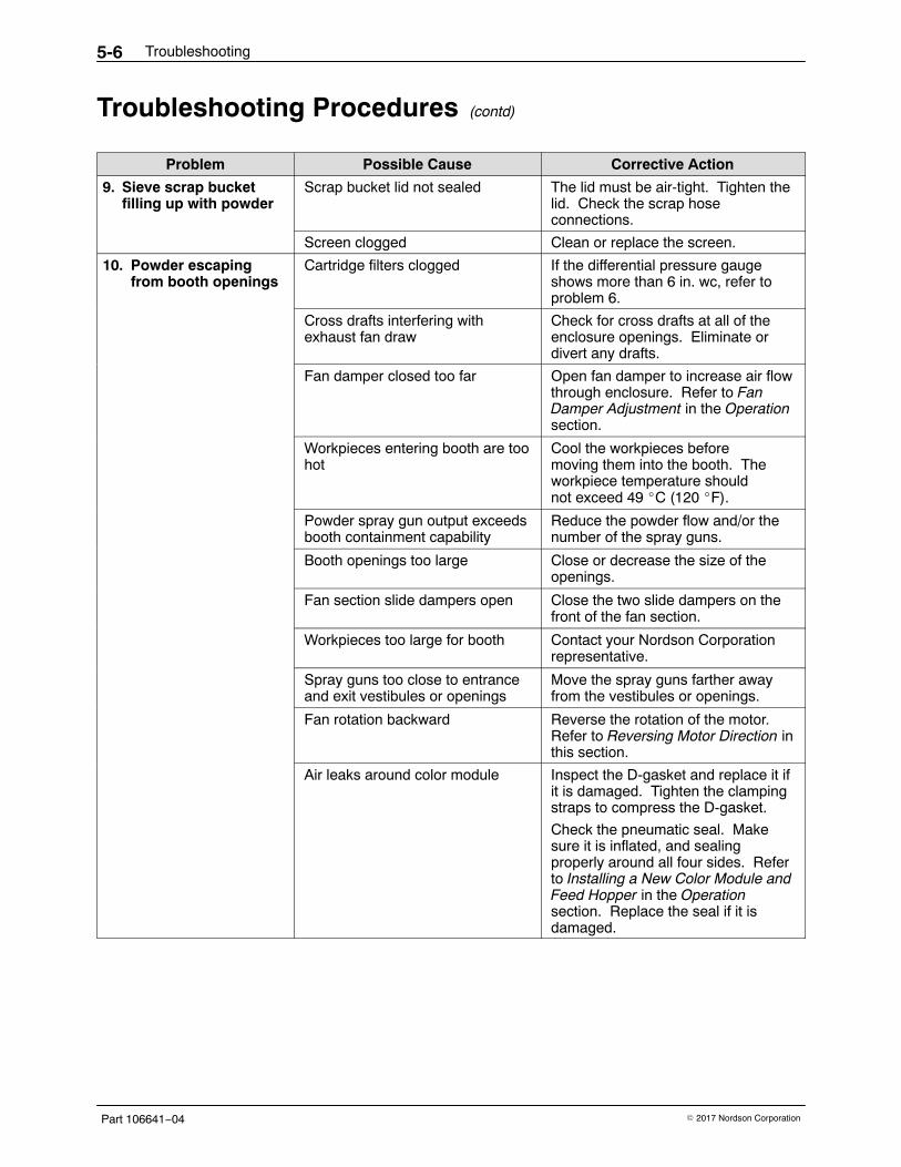
Troubleshooting5-6
Part 106641−04 � 2017 Nordson Corporation
Troubleshooting Procedures (contd)
Problem Possible Cause Corrective Action
9. Sieve scrap bucketfilling up with powder
Scrap bucket lid not sealed The lid must be air-tight. Tighten thelid. Check the scrap hoseconnections.
Screen clogged Clean or replace the screen.
10. Powder escapingfrom booth openings
Cartridge filters clogged If the differential pressure gaugeshows more than 6 in. wc, refer toproblem 6.
Cross drafts interfering withexhaust fan draw
Check for cross drafts at all of theenclosure openings. Eliminate ordivert any drafts.
Fan damper closed too far Open fan damper to increase air flowthrough enclosure. Refer to FanDamper Adjustment in the Operationsection.
Workpieces entering booth are toohot
Cool the workpieces beforemoving them into the booth. Theworkpiece temperature shouldnot exceed 49 �C (120 �F).
Powder spray gun output exceedsbooth containment capability
Reduce the powder flow and/or thenumber of the spray guns.
Booth openings too large Close or decrease the size of theopenings.
Fan section slide dampers open Close the two slide dampers on thefront of the fan section.
Workpieces too large for booth Contact your Nordson Corporationrepresentative.
Spray guns too close to entranceand exit vestibules or openings
Move the spray guns farther awayfrom the vestibules or openings.
Fan rotation backward Reverse the rotation of the motor.Refer to Reversing Motor Direction inthis section.
Air leaks around color module Inspect the D-gasket and replace it ifit is damaged. Tighten the clampingstraps to compress the D-gasket.
Check the pneumatic seal. Makesure it is inflated, and sealingproperly around all four sides. Referto Installing a New Color Module andFeed Hopper in the Operationsection. Replace the seal if it isdamaged.
Troubleshooting 5-7
Part 106641−04� 2017 Nordson Corporation
Reversing Motor DirectionImproperly connecting the exhaust fan and sieve motor starters will causethem to rotate in the wrong direction. If the exhaust fan is rotating in thewrong direction, powder will be blown out of the enclosure. If the sieverotates in the wrong direction, powder will back up in the accumulator. Usethe following procedures to check and correct, if necessary, the exhaust fanand sieve motor rotation direction.
Exhaust Fan Motor1. Turn on system electrical power.
2. Start the exhaust fan motor.
3. Observe the direction of fan rotation. The fan should rotate in thedirection indicated by the yellow arrow on the front of the fan section.The fan shaft should rotate clockwise when viewed from the sheave(pulley) end (from above the fan). If the rotation is backward, go to thenext step.
WARNING: Even with the electrical panel disconnect in the off position, theinput terminals at the top of the switch are still live. Do not touch them.Failure to observe this warning could result in serious injury or death.
4. Shut off system electrical power. Open the electrical panel door andreverse any two wires (L1, L2, or L3) connected to the fan motor starter(M407). Close the electrical panel door.
5. Turn on electrical power. Start the fan and check the rotation direction.
Sieve Motor1. Check your sieve manual for the proper motor rotation direction. If it is
rotating in the wrong direction, perform the next step.
WARNING: Even with the electrical panel disconnect in the off position, theinput terminals at the top of the switch are still live. Do not touch them.Failure to observe this warning could result in serious injury or death.
2. Shut off system electrical power. Open the electrical panel door.Reverse any two wires (L1, L2, or L3) connected to the sieve motorstarter (M412). Close the electrical panel door.
3. Restore system electrical power. Start the sieve and check the rotationdirection.
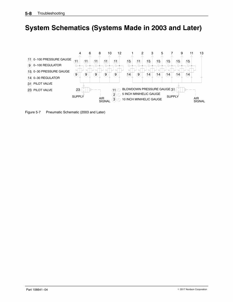
Troubleshooting5-8
Part 106641−04 � 2017 Nordson Corporation
System Schematics (Systems Made in 2003 and Later)
11
BLOWDOWN PRESSURE GAUGE
10 INCH MINIHELIC GAUGE
5 INCH MINIHELIC GAUGE23 PILOT VALVE
0−30 REGULATOR
0−30 PRESSURE GAUGE
0−100 REGULATOR
0−100 PRESSURE GAUGE
SIGNAL
31
14
15
PILOT VALVE
9
11
SUPPLY
23
AIR 3211
SUPPLY
31
AIRSIGNAL
11
9 9 9 9
64
11
8
11 11
9 14 9
1210
11
1
15
14 14 14
32
15
5
15 15
1414
15
97
15
1311
Figure 5-7 Pneumatic Schematic (2003 and Later)
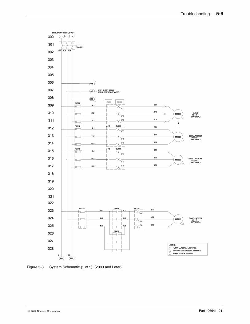
Troubleshooting 5-9
Part 106641−04� 2017 Nordson Corporation
M503 OL503
Figure 5-8 System Schematic (1 of 5) (2003 and Later)
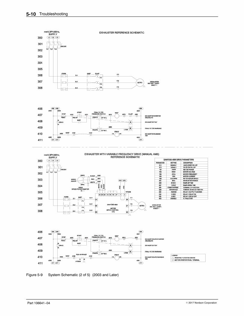
Troubleshooting5-10
Part 106641−04 � 2017 Nordson Corporation
Figure 5-9 System Schematic (2 of 5) (2003 and Later)
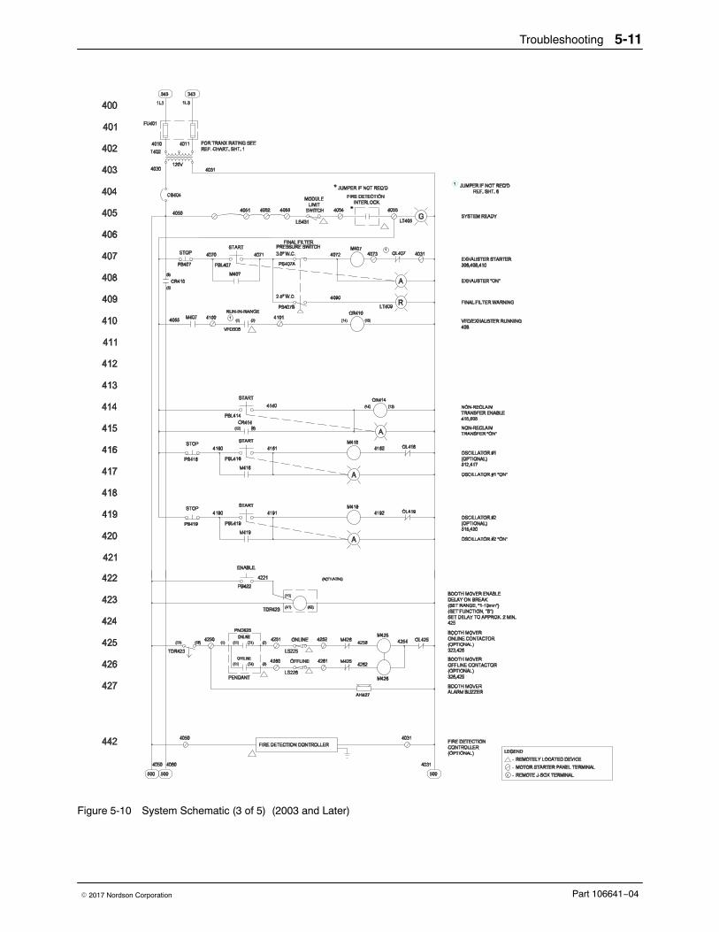
Troubleshooting 5-11
Part 106641−04� 2017 Nordson Corporation
Figure 5-10 System Schematic (3 of 5) (2003 and Later)
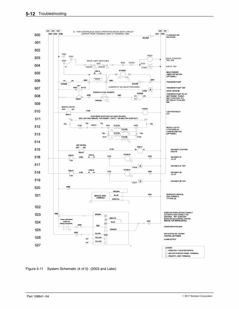
Troubleshooting5-12
Part 106641−04 � 2017 Nordson Corporation
LS503BLS503A LT504A
5031SIEVE LIMIT SWITCHES
4080
50335032 OL503
M5035030
5060
✥
*M503
FOR CONTINUOUS SIEVE OPERATION MOVE SIEVE CIRCUITJUMPER FROM TERMINAL 5060 TO TERMINAL 4080
✥
SIEVE STARTER309, 506
SIEVE ”ON”
*JUMPER IF NO SIEVE PROVIDED
Figure 5-11 System Schematic (4 of 5) (2003 and Later)
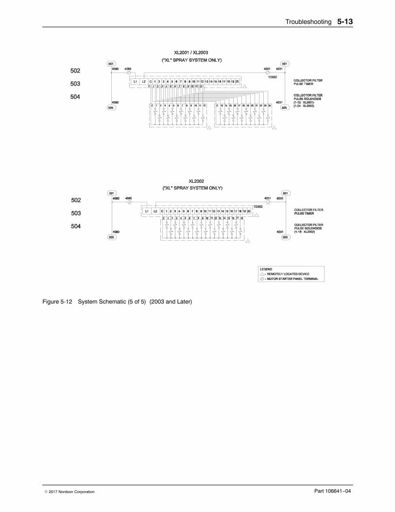
Troubleshooting 5-13
Part 106641−04� 2017 Nordson Corporation
Figure 5-12 System Schematic (5 of 5) (2003 and Later)
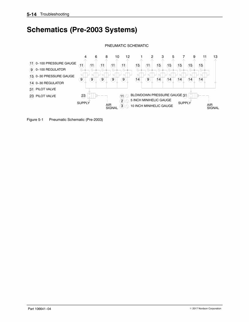
Troubleshooting5-14
Part 106641−04 � 2017 Nordson Corporation
Schematics (Pre-2003 Systems)
11
BLOWDOWN PRESSURE GAUGE
10 INCH MINIHELIC GAUGE
5 INCH MINIHELIC GAUGE23 PILOT VALVE
0−30 REGULATOR
0−30 PRESSURE GAUGE
0−100 REGULATOR
0−100 PRESSURE GAUGE
SIGNAL
31
14
15
PILOT VALVE
9
11
SUPPLY
23
AIR 3211
SUPPLY
31
AIRSIGNAL
11
9 9 9 9
64
11
8
11 11
9 14 9
1210
11
1
15
14 14 14
32
15
5
15 15
1414
15
97
15
1311
PNEUMATIC SCHEMATIC
Figure 5-1 Pneumatic Schematic (Pre-2003)
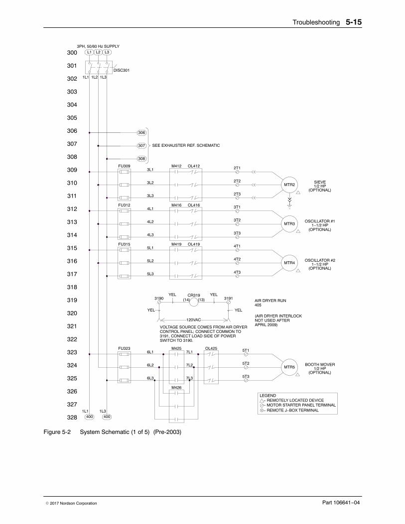
Troubleshooting 5-15
Part 106641−04� 2017 Nordson Corporation
3PH, 50/60 Hz SUPPLY
AIR DRYER RUN
LEGEND
318
328
325
326
327
324
323
322
321
319
320
4004001L1 1L3
M426
M425
VOLTAGE SOURCE COMES FROM AIR DRYERCONTROL PANEL; CONNECT COMMON TO3191, CONNECT LOAD SIDE OF POWERSWITCH TO 3190.
FU323
6L3
6L1
6L2
YEL
3190YEL
7L3
7L2
7L1OL425
5T3
5T1
5T2
120VAC
CR319(14) (13)
YEL
YEL
3191
405
317
316
315
314
311
313
312
310
309
304
308
307
306
305
303
302
301
300
OL412M412FU309
M419
M416
FU315
5L2
5L3
5L1
4L3
FU312
3L3
4L1
4L2
3L1
3L2
OL419
4T3
4T2
4T1
3T3
OL416
3T2
3T1
2T2
2T3
2T1
SEE EXHAUSTER REF. SCHEMATIC
308
307
306
1L1 1L2 1L3
L3L1 L2
DISC301
− REMOTE J−BOX TERMINAL
− REMOTELY LOCATED DEVICE − MOTOR STARTER PANEL TERMINAL
(OPTIONAL)1/2 HP
BOOTH MOVERMTR5
1−1/2 HP
(OPTIONAL)
(OPTIONAL)
OSCILLATOR #21−1/2 HPMTR4
(OPTIONAL)
OSCILLATOR #1
1/2 HP
MTR3
MTR2SIEVE
(AIR DRYER INTERLOCKNOT USED AFTERAPRIL 2009)
Figure 5-2 System Schematic (1 of 5) (Pre-2003)
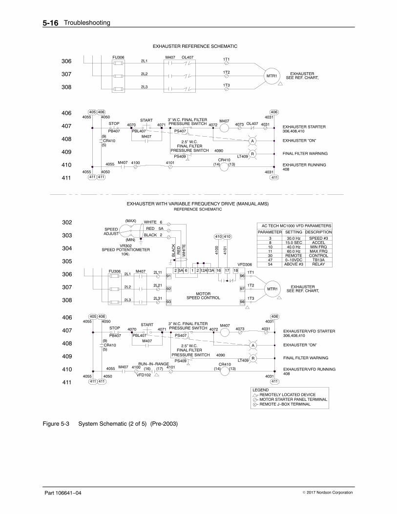
Troubleshooting5-16
Part 106641−04 � 2017 Nordson Corporation
LEGEND
REMOTE30 CONTROL
RUN−IN−RANGE
4055 4050
411
− REMOTE J−BOX TERMINAL
− REMOTELY LOCATED DEVICE − MOTOR STARTER PANEL TERMINAL
411 411
409
410
408
407
406
305
306
307
308
406405
CR410
4055
(5)
4055
PB407(9)
4050
STOP
VFD102
M407 4100 (16) (17)
START
M407PBL407
4070
FU306
2L21
2L3
2L2
2L31
M4072L1 2L11
4031411
PRESSURE SWITCHFINAL FILTER
2.5” W.C.
PS409
4101
PRESSURE SWITCH3” W.C. FINAL FILTER
PS407
A
(13)CR410
(14)
LT409 R
M4074073
13A
SPEED CONTROL93
92MOTOR
65A291
12A21
1T2
98
97
1T3
1716 1896
1T1
VFD306
406
EXHAUSTER/VFD STARTER306,408,410
EXHAUSTER ”ON”
EXHAUSTER/VFD RUNNING
FINAL FILTER WARNING
408
4031
4031
SEE REF. CHART,EXHAUSTERMTR1
4754
0−10VDCABOVE #3
TB13ARELAY
EXHAUSTER WITH VARIABLE FREQUENCY DRIVE (MANUAL AMS)
EXHAUSTER REFERENCE SCHEMATIC
4071
410
302
304
303
411
SPEED POTENTIOMETER
SPEEDADJUST
(MIN)
VR302
10K
RED
BLACK
5A
2
(MAX) WHITE 6
4114055 4050
411
4055 M407 4100
406
407
408
409
308
307
306
CR410(5)
PB407(9)
4054055
4064050
STOP
M407PBL407
START4070
FU306
2L3
2L2
2L1
LT409PS409
REFERENCE SCHEMATIC
BLA
CK
WH
ITE
RE
D
4100
4101
410 410
4101 (13)CR410
(14)
AC TECH MC1000 VFD PARAMETERS
10
PARAMETER
8
11
315.0 SEC40.0 Hz60.0 Hz
SETTING
30.0 Hz
MIN FRQMAX FRQ
ACCEL
DESCRIPTION
SPEED #3
EXHAUSTER RUNNING
4031411
408
OL4074072
4090PRESSURE SWITCHFINAL FILTER
2.5” W.C.
PS407
PRESSURE SWITCH3” W.C. FINAL FILTER
A
R
M4074073
OL407M407
1T3
1T2
1T1
EXHAUSTER STARTER306,408,410
EXHAUSTER ”ON”
FINAL FILTER WARNING
4064031
4031
EXHAUSTERSEE REF. CHART,MTR1
4071 4072
4090
Figure 5-3 System Schematic (2 of 5) (Pre-2003)
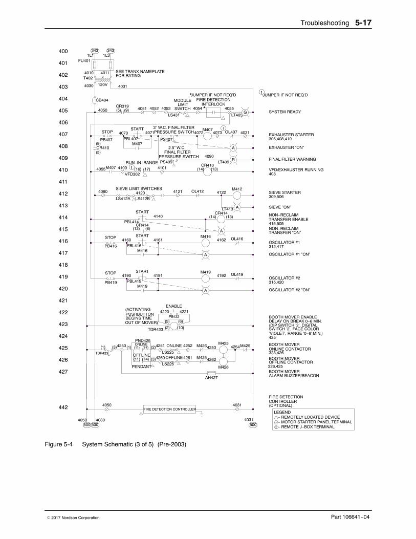
Troubleshooting 5-17
Part 106641−04� 2017 Nordson Corporation
4031
4031
M425
G
A
442
422
424
423
427
426
425
421
4050500500
4080
(3)
(2)
TDR423
(ACTIVATINGPUSHBUTTONBEGINS TIMEOUT OF MOVER)
FIRE DETECTION CONTROLLER4050
TDR423
PENDANT
OFFLINE(11) (74)
(1) (1)(3)4250PND425ONLINE(11) (74)
M425OFFLINE4260LS225
LS226
4261
4031
M426
AH427
4262
M426
(6)(5)
ONLINE4251
(2)
4252
(10)
PB422
ENABLE4220 4221
M4254253 4254
402
403
401
400
413
414
412
411
409
410
408
407
405
406
404
420
419
418
416
417
415
(14) (13)4101(17)(16)41004055
SIEVE LIMIT SWITCHES
(8)(12)
4190
PB419
STOP
M419PBL419
START
4160
PB416
STOP
PBL416M416
START
4080
LS412A LS412B
CR414PBL414
START
VFD302
4120
A
4191
4161
4192M419 OL419
4162
A
M416 OL416
OL412
4140
4121
CR414(14) (13)
LT413 A
4122M412
RUN−IN−RANGE
4071
40524051CR319
CR410
PB407
STOP
4050
(5)
(9)PBL407
M407
M407
START4070
(5) (9)
1L3
120V
4011T402
CB404
4030
FU401
4010
3431L1
4031
FOR RATINGSEE TRANX NAMEPLATE
343
*SWITCH 405540544053
PS407
2.5” W.C.FINAL FILTER
PRESSURE SWITCHPS409
4090
3” W.C. FINAL FILTER
LS431
PRESSURE SWITCH4072
LT409CR410
R
A
M4074073 OL407
LT405
JUMPER IF NOT REQ’DMODULE
LIMIT
*FIRE DETECTION
INTERLOCK
OSCILLATOR #2 ”ON”
(OPTIONAL)
500
ALARM BUZZER/BEACON
CONTROLLERFIRE DETECTION
326,425OFFLINE CONTACTORBOOTH MOVER
323,426
BOOTH MOVER
BOOTH MOVER ENABLEDELAY ON BREAK 0−6 MIN.
BOOTH MOVERONLINE CONTACTOR
(DIP SWITCH ’2’, DIGITAL
− REMOTELY LOCATED DEVICE
− REMOTE J−BOX TERMINAL − MOTOR STARTER PANEL TERMINAL
LEGEND
VFD/EXHAUSTER RUNNING
NON−RECLAIMTRANSFER ”ON”
OSCILLATOR #1 ”ON”
OSCILLATOR #2315,420
OSCILLATOR #1312,417
TRANSFER ENABLE415,505
NON−RECLAIM
SIEVE ”ON”
309,506
408
SIEVE STARTER
FINAL FILTER WARNING
EXHAUSTER ”ON”
EXHAUSTER STARTER306,408,410
SYSTEM READY
JUMPER IF NOT REQ’D
’VIOLET’, RANGE ’0−6’ MIN.)SWITCH ’2’, FACE COLOR
425
1
1
1
Figure 5-4 System Schematic (3 of 5) (Pre-2003)
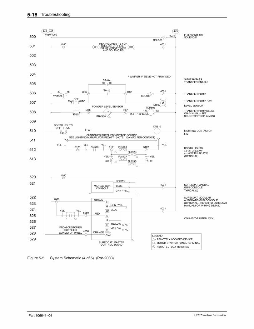
Troubleshooting5-18
Part 106641−04 � 2017 Nordson Corporation
524
529
528
527
525
526
523
522
521
520
511
513
512
510
509
504
508
507
506
505
503
502
501
500
443443443
501501
4050 4080
4080 REF. FIGURE 5−1E FORCOLLECTOR FILTERPULSE−VALVE TIMER
AND SOLENOIDS
SOL500
4031
(5) (9) 5060
TDR508
MAN AUTO
OFF
SS507
BOOTH LIGHTS
OFF
ON
SS510
5100
5080POWDER LEVEL SENSOR
PRX508
*M412
CR414
* JUMPER IF SIEVE NOT PROVIDED
5061
SOL506
4031
LT507TDR508
(14) (13)5081
(1.8 − 180 SEC)
CN510
(5)(9)
*
*
A
CUSTOMER SUPPLIED VOLTAGE SOURCE.SEE LIGHTING MANUAL FOR REQM’T. (NOTE: 10A MAX PER CONTACT)
YEL5120 CN510 5121 FL512A 5122
FL512B
FL513A
FL513B 5122
YEL YEL YEL
YELYEL
5121
4080
BROWN
BLUE
GRN / YEL
MANUAL GUNCONSOLE
4031
RED
ORANGE
YELLOW
SURECOAT MASTERCONTROL BOARD
FROM CUSTOMERSUPPLIED
CONVEYOR PANEL
5250YEL
L1
G
L2
E
F
G
H
N / C
4080
YEL
N / C
BROWN
BLUE
GRN / YEL
YELLOW
4031
FLUIDIZING AIRSOLENOID
SIEVE BYPASSTRANSFER ENABLE
TRANSFER PUMP
TRANSFER PUMP ”ON”
LEVEL SENSOR
TRANSFER PUMP DELAYON 0−3 MIN. − SETSELECTOR TO X1 & M506
LIGHTING CONTACTOR512
BOOTH LIGHTS4 FIXTURES W/4 − 40W BULBS PER(OPTIONAL)
SURECOAT MANUALGUN CONSOLETYPICAL (2)
SURECOAT MODULARAUTOMATIC GUN CONSOLE(OPTIONAL − REFER TO SURECOATMANUAL FOR WIRING DETAIL)
CONVEYOR INTERLOCK
LEGEND
− REMOTE J−BOX TERMINAL
− REMOTELY LOCATED DEVICE − MOTOR STARTER PANEL TERMINAL
4031
AUX4050
Figure 5-5 System Schematic (4 of 5) (Pre-2003)
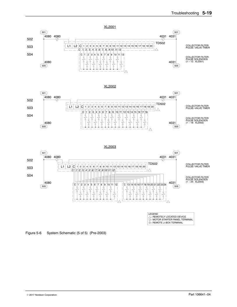
Troubleshooting 5-19
Part 106641−04� 2017 Nordson Corporation
504
503
502
501
505
501
505
L1C
L2 C 1 2 3 4 5 6 7 8 9 10 11 12 13 14 15 16 17 18 19 20
1 2 3 4 5 6 7 8 9 10 11 12
C 1 2 3 4 5 6 7 8 9 10 11 12
40804080 40314031
4080 4031
TD502
501
505
501
505
L1
C
L2 C 1 2 3 4 5 6 7 8 9 10 11 12 13 14 15 16 17 18 19 20
1 2 3 4 5 6 7 8 9 10 11 12
40804080 40314031
4080 4031
TD502
501
505
501
505
L1C
L2 C 1 2 3 4 5 6 7 8 9 10 11 12 13 14 15 16 17 18 19 20
1 2 3 4 5 6 7 8 9 10 11 12
C 1 2 3 4 5 6 7 8 9 10 11 12
40804080 40314031
4080 4031
TD502
13 14 15 16 17 18
C 13 14 15 16 17 18 19 20 21 22 23 24
COLLECTOR FILTERPULSE−VALVE TIMER
COLLECTOR FILTERPULSE SOLENOIDS(1 − 12: XL2001)
COLLECTOR FILTERPULSE−VALVE TIMER
COLLECTOR FILTERPULSE SOLENOIDS(1 − 18: XL2002)
COLLECTOR FILTERPULSE−VALVE TIMER
COLLECTOR FILTERPULSE SOLENOIDS(1 − 24: XL2003)
504
503
502
504
503
502
LEGEND
− REMOTE J−BOX TERMINAL
− REMOTELY LOCATED DEVICE − MOTOR STARTER PANEL TERMINAL
XL2001
XL2002
XL2003
Figure 5-6 System Schematic (5 of 5) (Pre-2003)
Troubleshooting5-20
Part 106641−04 � 2017 Nordson Corporation
Repair 6-1
Part 106641−04� 2017 Nordson Corporation
Section 6Repair
WARNING: Allow only qualified personnel to perform the following tasks.Follow the safety instructions in this document and all other relateddocumentation.
NOTE: The Excel 2000 Series powder coating systems are FM (FactoryMutual) approved. Use only approved Nordson Corporation replacementparts. Using unapproved parts may void FM approval of your system.Contact your Nordson Corporation representative for more information.
Final Filter Replacement WARNING: Before performing this procedure, shut off electrical power atthe system electrical panel. Lock and tag the switch. Failure to observethis warning could result in personal injury or death.
1. Shut off the exhaust fan. Shut off electrical power at the systemelectrical panel. Lock and tag the disconnect switch.
2. See Figure 6-1. Unscrew and remove the threaded knobs (3) andbrackets (2) securing the final filters (1) to the fan section. The filters willstay in place.
3. Remove the old filters and discard them.
4. Check the interior of the fan housing. If you see large amounts ofpowder inside the housing, powder is leaking through the cartridge filtersor mounting plate. Fix the leak before starting the system.
NOTE: Do not use damaged filters.
5. Remove the new filters from their cartons. Inspect the filter housings,gaskets, and media for damage.
6. Insert the new filters into the openings.
7. Install the brackets over the threaded studs. Thread the knobs onto thestuds.
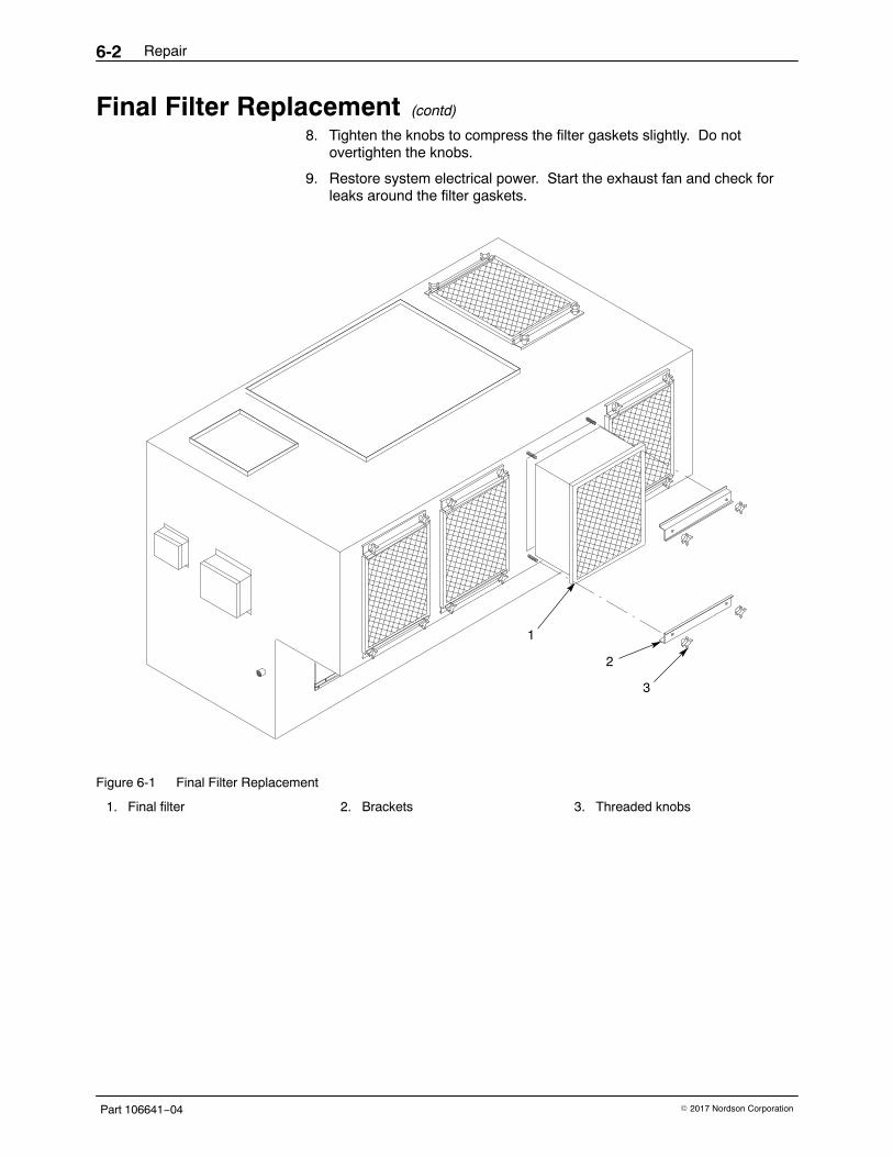
Repair6-2
Part 106641−04 � 2017 Nordson Corporation
Final Filter Replacement (contd)
8. Tighten the knobs to compress the filter gaskets slightly. Do notovertighten the knobs.
9. Restore system electrical power. Start the exhaust fan and check forleaks around the filter gaskets.
2
1
3
Figure 6-1 Final Filter Replacement
1. Final filter 2. Brackets 3. Threaded knobs
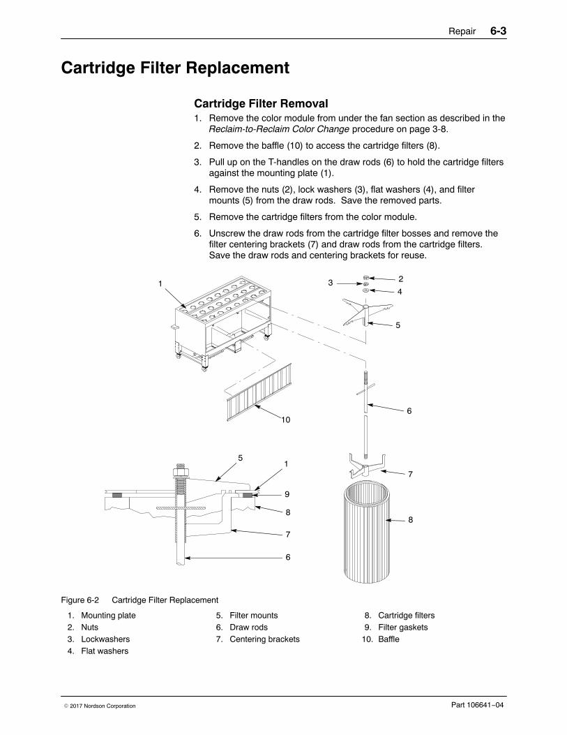
Repair 6-3
Part 106641−04� 2017 Nordson Corporation
Cartridge Filter Replacement
Cartridge Filter Removal 1. Remove the color module from under the fan section as described in the
Reclaim-to-Reclaim Color Change procedure on page 3-8.
2. Remove the baffle (10) to access the cartridge filters (8).
3. Pull up on the T-handles on the draw rods (6) to hold the cartridge filtersagainst the mounting plate (1).
4. Remove the nuts (2), lock washers (3), flat washers (4), and filtermounts (5) from the draw rods. Save the removed parts.
5. Remove the cartridge filters from the color module.
6. Unscrew the draw rods from the cartridge filter bosses and remove thefilter centering brackets (7) and draw rods from the cartridge filters.Save the draw rods and centering brackets for reuse.
21 34
5
6
7
8
51
9
8
7
6
10
Figure 6-2 Cartridge Filter Replacement
1. Mounting plate2. Nuts3. Lockwashers4. Flat washers
5. Filter mounts6. Draw rods7. Centering brackets
8. Cartridge filters9. Filter gaskets
10. Baffle
Repair6-4
Part 106641−04 � 2017 Nordson Corporation
Cartridge Filter Installation
CAUTION: Do not use any cartridge filters other than those specified foryour system. Using unapproved cartridge filters could seriously affect theoperation and performance of your system, as well as void FM approvals.Do not use damaged filters.
Carefully inspect the new cartridge filters for
� cuts or other damage to the rubber gaskets
� bent or dented end caps
� holes or other damage to the filter media
1. See Figure 6-2. Thoroughly clean the sealing surfaces on the undersideof the mounting plate (1). Dirty surfaces will prevent the cartridge filtergaskets from sealing properly and allow powder to leak into the fansection.
2. Insert the threaded end of the draw rods (6) through the centeringbrackets (7).
3. Install the draw rods and centering brackets in the new cartridgefilters (8).
4. Screw the draw rods into the filter bosses. Tighten the draw rods byhand.
5. Center the cartridge filters under the filter openings in the mountingplate. Hold the cartridge filters up against the mounting plate.
6. Use the T-handles to pull the cartridge filters up against the filtermounting plates. Install the filter mounts (5) on the draw rods, makingsure the slots in the filter mounts slip over the T-handles.
7. Install the flat washers (4), lock washers (3), and nuts (2) on the drawrods.
8. Slip the ends of the filter mounts into the locating slots in the mountingplate, around the openings.
CAUTION: Do not overtighten the nuts, or you may damage the cartridgefilters.
9. Tighten the nuts until the filter mounts and centering brackets aretouching. This will compress the filter gaskets (9) and seal thecartridges against the mounting plate.
10. Install the color module as described in Installing a New Color Moduleand Feed Hopper on page 3-10.
Repair 6-5
Part 106641−04� 2017 Nordson Corporation
Color Module Fluidizing Plate Replacement
Systems Made in 2003 or Later Use this procedure for systems manufactured after 2003. Fluidizing platereplacement will only be necessary if the plates are contaminated ordamaged.
Preparation1. Start the transfer pumps and pump as much as possible of the powder
in the color module hoppers back into the feed hopper. If the powder iscontaminated, pump it into a scrap bucket.
2. Remove the color module from under the fan section as described in theReclaim-to-Reclaim Color Change procedure on page 3-8.
3. Remove the baffle, transfer pumps, and cartridge filters from the colormodule.
4. Remove all the powder from the color module hoppers. Vacuum thehoppers and fluidizing plates and wipe them clean with damp, lint-freecloths. Do not use tack cloths.
Replacement1. See Figure 6-3. Unscrew the plenum clamp screws (5) about 6−10 mm
(0.25−0.375 in.) to clear the fluidizing plate gaskets (2). Remove theplenum clamp (4).
2. Slide the fluidizing plenums (3), fluidizing plates (1) and gaskets (2) outfrom under the color module.
3. Separate the old fluidizing plates (1) and gaskets. Discard the oldfluidizing plates.
4. Clean the plenums and hopper flanges.
5. Assemble the fluidizing plenums, gaskets, and fluidizing plates.
6. Slide the plenum assembly into the slot under the color module.
7. Install the plenum clamp over the fluidizing plenums and hopper flanges.Align the plenum and hopper flanges on both ends of the assembly.
8. Tighten the plenum clamp screws with a torque wrench to 2.8 N�m(25 in.-lb) beginning with the outside screws and work toward the centerof the clamp. This will prevent flange distortion and fluidizing platedamage.
9. Install the cartridge filters, transfer pumps, and baffle. Roll the colormodule into position under the fan section. Connect the hoses, quickdisconnects, tubing, power cords, and level sensor.
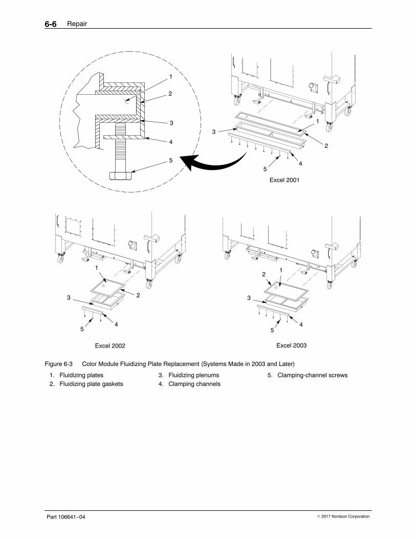
Repair6-6
Part 106641−04 � 2017 Nordson Corporation
Excel 2003
54
21
3
Excel 2001
54
2
1
3
5
4
3
2
1
54
2
1
3
Excel 2002
Figure 6-3 Color Module Fluidizing Plate Replacement (Systems Made in 2003 and Later)
1. Fluidizing plates2. Fluidizing plate gaskets
3. Fluidizing plenums4. Clamping channels
5. Clamping-channel screws
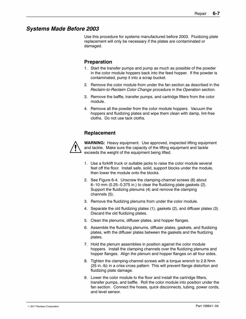
Repair 6-7
Part 106641−04� 2017 Nordson Corporation
Systems Made Before 2003 Use this procedure for systems manufactured before 2003. Fluidizing platereplacement will only be necessary if the plates are contaminated ordamaged.
Preparation1. Start the transfer pumps and pump as much as possible of the powder
in the color module hoppers back into the feed hopper. If the powder iscontaminated, pump it into a scrap bucket.
2. Remove the color module from under the fan section as described in theReclaim-to-Reclaim Color Change procedure in the Operation section.
3. Remove the baffle, transfer pumps, and cartridge filters from the colormodule.
4. Remove all the powder from the color module hoppers. Vacuum thehoppers and fluidizing plates and wipe them clean with damp, lint-freecloths. Do not use tack cloths.
Replacement
WARNING: Heavy equipment. Use approved, inspected lifting equipmentand tackle. Make sure the capacity of the lifting equipment and tackleexceeds the weight of the equipment being lifted.
1. Use a forklift truck or suitable jacks to raise the color module severalfeet off the floor. Install safe, solid, support blocks under the module,then lower the module onto the blocks.
2. See Figure 6-4. Unscrew the clamping-channel screws (6) about6−10 mm (0.25−0.375 in.) to clear the fluidizing plate gaskets (2).Support the fluidizing plenums (4) and remove the clampingchannels (5).
3. Remove the fluidizing plenums from under the color module.
4. Separate the old fluidizing plates (1), gaskets (2), and diffuser plates (3).Discard the old fluidizing plates.
5. Clean the plenums, diffuser plates, and hopper flanges.
6. Assemble the fluidizing plenums, diffuser plates, gaskets, and fluidizingplates, with the diffuser plates between the gaskets and the fluidizingplates.
7. Hold the plenum assemblies in position against the color modulehoppers. Install the clamping channels over the fluidizing plenums andhopper flanges. Align the plenum and hopper flanges on all four sides.
8. Tighten the clamping-channel screws with a torque wrench to 2.8 N�m(25 in.-lb) in a criss-cross pattern This will prevent flange distortion andfluidizing plate damage.
9. Lower the color module to the floor and install the cartridge filters,transfer pumps, and baffle. Roll the color module into position under thefan section. Connect the hoses, quick disconnects, tubing, power cords,and level sensor.
Repair6-8
Part 106641−04 � 2017 Nordson Corporation
2
1
3
4
5
6
6
5
4
3
2
1
Figure 6-4 Color Module Fluidizing Plate Replacement (Systems Made Before 2003)
1. Fluidizing plates2. Fluidizing plate gaskets
3. Diffuser plates4. Fluidizing plenums
5. Clamping channels6. Clamping-channel screws
Repair 6-9
Part 106641−04� 2017 Nordson Corporation
Feed Hopper Fluidizing Plate Replacement
Preparation1. Pump as much powder as you can from the feed hopper. Disconnect
the powder feed hoses, transfer hoses, accumulator vent hose, and10-tube quick-disconnects from the feed hopper, powder pumps, andaccumulator.
2. Rotate the level sensor and pull it from its mounting in the side of thefeed hopper.
3. Unplug the sieve power cords (electrically driven sieves only).Disconnect the feed-hopper ground wire.
4. Remove the feed hopper from the color module and roll it to a cleanwork area.
5. Remove the powder from the hopper and thoroughly clean the hopper,accumulator, and sieve.
Replacement1. See Figure 6-5. Block up the plenum (5) so the plenum and feed
hopper flanges will not bend when you start removing the clampingchannels (3).
2. Loosen screws (4) about 6−10 mm (0.25−0.375 in.) to clear thegasket (2). Remove the clamping channels.
3. Remove the plenum and the fluidizing plate (1) from under the feedhopper.
4. Clean the plenum interior and the plenum and feed hopper flanges.
5. Position the new fluidizing plate and gasket on the plenum.
6. Slide the plenum and fluidizing plate under the hopper. Align the edgesof the feed hopper flange, gasket, and plenum flange evenly on allsides. Block the plenum to hold it in position.
7. Install the clamping channels over the plenum and hopper flanges.Tighten the clamping-channel screws with a torque wrench to 2.8 N�m(25 in.-lb) in a criss-cross pattern. This prevents flange distortion andfluidizing plate damage.
8. Attach the feed hopper to the color module. Connect the hoses,quick-disconnects, power cords, and ground wires. Install the levelsensor in its mounting.
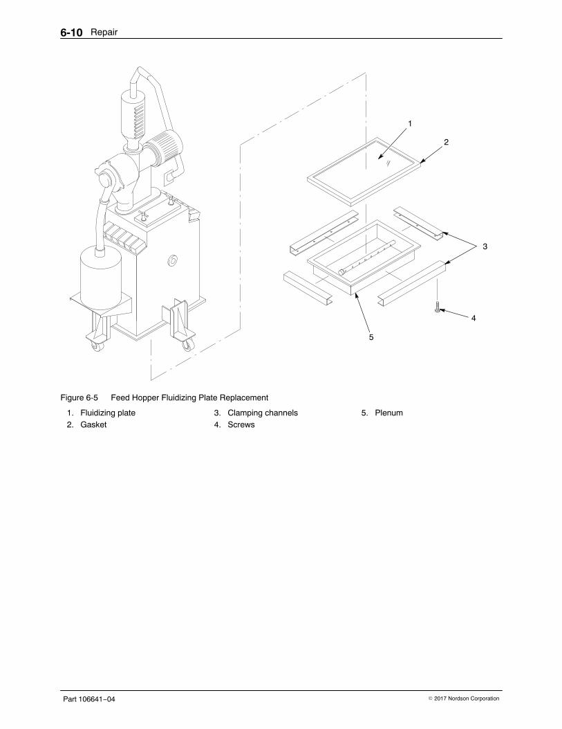
Repair6-10
Part 106641−04 � 2017 Nordson Corporation
2
1
3
4
5
Figure 6-5 Feed Hopper Fluidizing Plate Replacement
1. Fluidizing plate2. Gasket
3. Clamping channels4. Screws
5. Plenum
Repair 6-11
Part 106641−04� 2017 Nordson Corporation
Vibratory Sieve Repair1. Open the feed hopper lid. Reach inside the hopper and disconnect the
sieve ground wire.
2. Remove the bolts and washers from the hopper cover.
3. Lift the cover (with the accumulator and sieve attached) off the hopper.Block up the cover to prevent damage to the screen assembly on theunderside.
4. Unfasten the two toggle clamps and remove the screen basket. Discardany scrap powder and vacuum out the basket. Replace the basket if itis damaged. If no further disassembly of the sieve is necessary,reattach the basket and disregard steps 5 through 7.
5. To remove the air motor, disconnect the two air lines. Remove the boltand spacer.
NOTE: When you perform step 6, note the position of the screws, washers,nuts, rubber grommets or washers, and gaskets.
6. Remove the accumulator from the sieve, and disassemble the rest ofthe sieve.
7. Clean powder residue from the accumulator and sieve parts.
8. Assemble the sieve and install it on the hopper. Cap unusedaccumulator inlet tubes.
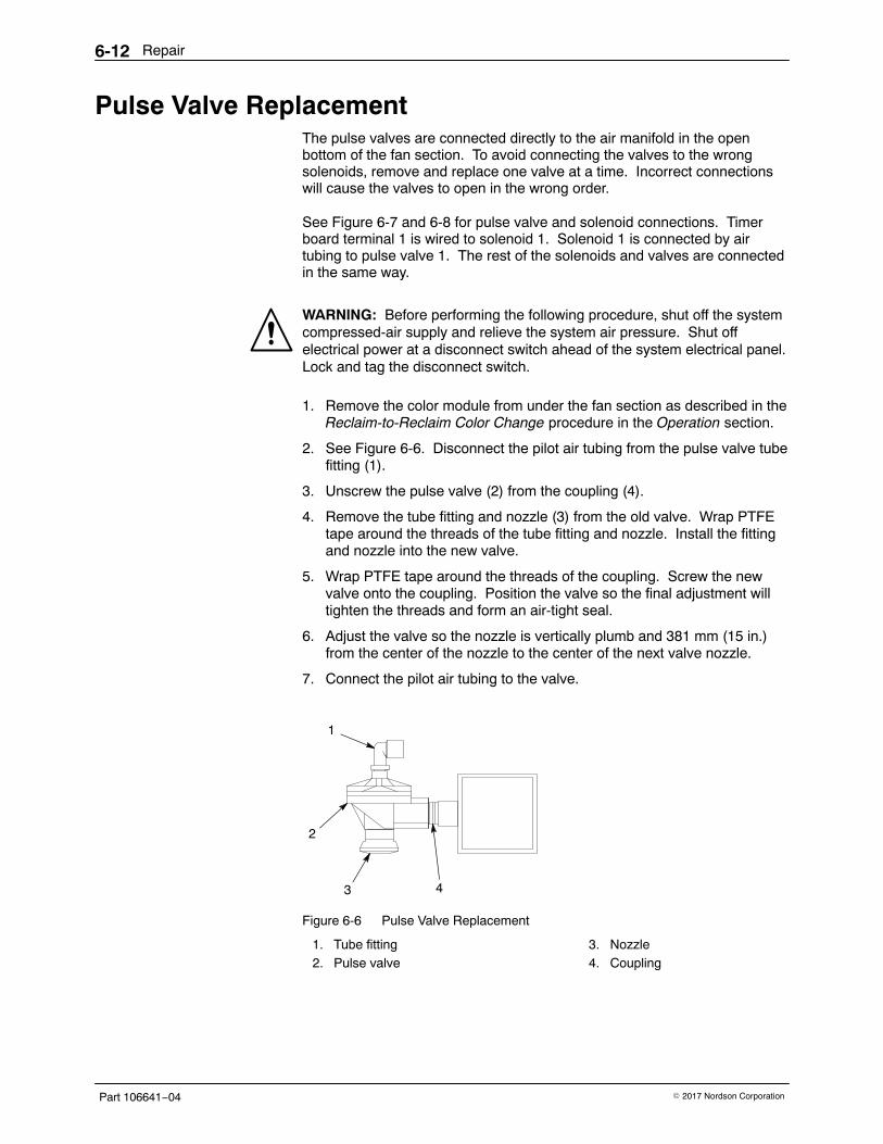
Repair6-12
Part 106641−04 � 2017 Nordson Corporation
Pulse Valve Replacement The pulse valves are connected directly to the air manifold in the openbottom of the fan section. To avoid connecting the valves to the wrongsolenoids, remove and replace one valve at a time. Incorrect connectionswill cause the valves to open in the wrong order.
See Figure 6-7 and 6-8 for pulse valve and solenoid connections. Timerboard terminal 1 is wired to solenoid 1. Solenoid 1 is connected by airtubing to pulse valve 1. The rest of the solenoids and valves are connectedin the same way.
WARNING: Before performing the following procedure, shut off the systemcompressed-air supply and relieve the system air pressure. Shut offelectrical power at a disconnect switch ahead of the system electrical panel.Lock and tag the disconnect switch.
1. Remove the color module from under the fan section as described in theReclaim-to-Reclaim Color Change procedure in the Operation section.
2. See Figure 6-6. Disconnect the pilot air tubing from the pulse valve tubefitting (1).
3. Unscrew the pulse valve (2) from the coupling (4).
4. Remove the tube fitting and nozzle (3) from the old valve. Wrap PTFEtape around the threads of the tube fitting and nozzle. Install the fittingand nozzle into the new valve.
5. Wrap PTFE tape around the threads of the coupling. Screw the newvalve onto the coupling. Position the valve so the final adjustment willtighten the threads and form an air-tight seal.
6. Adjust the valve so the nozzle is vertically plumb and 381 mm (15 in.)from the center of the nozzle to the center of the next valve nozzle.
7. Connect the pilot air tubing to the valve.
3
1
2
4
Figure 6-6 Pulse Valve Replacement
1. Tube fitting2. Pulse valve
3. Nozzle4. Coupling
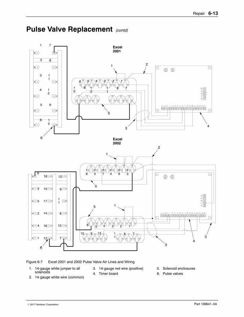
Repair 6-13
Part 106641−04� 2017 Nordson Corporation
Pulse Valve Replacement (contd)
2345
1
2
3
4
5
6
8
9
10
11
12
16
7
8
11
12
9
10
11
13
16
14
17
15
186
6 1
2
3
4
5
7
8
9
10
12
13
14
15
16
17
18
2345
7811
12910
1
Excel2001
Excel2002
7
1 2
34
5
6
4
1
2
3
3
1
5
5
6
Figure 6-7 Excel 2001 and 2002 Pulse Valve Air Lines and Wiring
1. 14-gauge white jumper to allsolenoids
2. 14-gauge white wire (common)
3. 14-gauge red wire (positive)4. Timer board
5. Solenoid enclosures6. Pulse valves
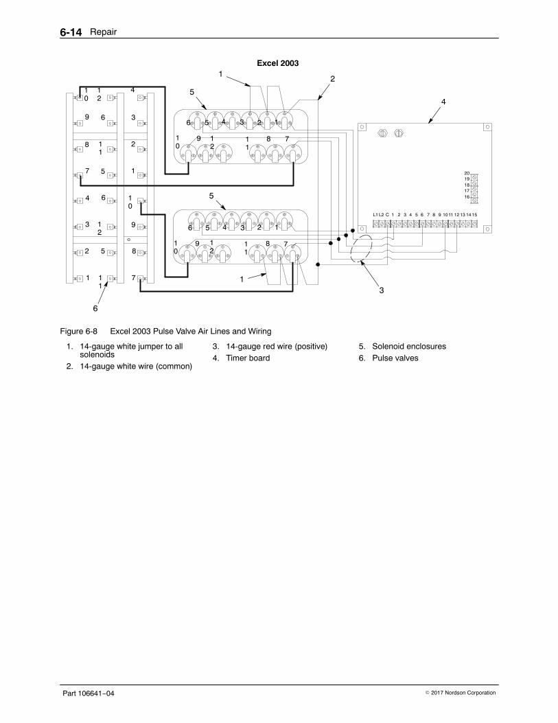
Repair6-14
Part 106641−04 � 2017 Nordson Corporation
5
8
9
1
6
7
10
11
12
4 5 6 7 8 9 1011 12 13 14 15
1617181920
L1 L2 C 1 2 3
2
3
4
5
6
12
5
11
4
3
2
1
10
9
8
7
12346
7811
12
910
123456
7811
12
910
Excel 2003
3
21
1
4
5
5
6
Figure 6-8 Excel 2003 Pulse Valve Air Lines and Wiring
1. 14-gauge white jumper to allsolenoids
2. 14-gauge white wire (common)
3. 14-gauge red wire (positive)4. Timer board
5. Solenoid enclosures6. Pulse valves
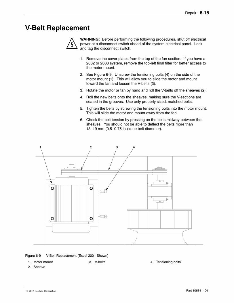
Repair 6-15
Part 106641−04� 2017 Nordson Corporation
V-Belt Replacement
WARNING: Before performing the following procedures, shut off electricalpower at a disconnect switch ahead of the system electrical panel. Lockand tag the disconnect switch.
1. Remove the cover plates from the top of the fan section. If you have a2002 or 2003 system, remove the top-left final filter for better access tothe motor mount.
2. See Figure 6-9. Unscrew the tensioning bolts (4) on the side of themotor mount (1). This will allow you to slide the motor and mounttoward the fan and loosen the V-belts (3).
3. Rotate the motor or fan by hand and roll the V-belts off the sheaves (2).
4. Roll the new belts onto the sheaves, making sure the V-sections areseated in the grooves. Use only properly sized, matched belts.
5. Tighten the belts by screwing the tensioning bolts into the motor mount.This will slide the motor and mount away from the fan.
6. Check the belt tension by pressing on the belts midway between thesheaves. You should not be able to deflect the belts more than13−19 mm (0.5−0.75 in.) (one belt diameter).
32 41
Figure 6-9 V-Belt Replacement (Excel 2001 Shown)
1. Motor mount2. Sheave
3. V-belts 4. Tensioning bolts
Repair6-16
Part 106641−04 � 2017 Nordson Corporation
Motor and Motor Sheave Replacement
WARNING: Before performing the following procedures, shut off electricalpower at the system electrical panel. Lock and tag the disconnect switch.
WARNING: Heavy equipment. Use approved, inspected lifting equipmentand tackle. Make sure the capacity of the lifting equipment and tackleexceeds the weight of the equipment being lifted.
Motor Replacement NOTE: You do not have to remove the motor from the fan section toreplace the motor sheave. Refer to the Motor Sheave Replacementprocedure.
Motor Removal 1. Remove the motor access plate.
2. See Figure 6-10. Remove the cover from the motor junction box (3).Tag and disconnect the wiring from the motor leads. Disconnect theconduit (4) from the junction box.
3. Remove the V-belts, as described in the V-Belt Replacement procedure,from the motor sheave (1).
4. Secure a heavy-duty sling or chains around the motor (2). Attach thesling or chains to a chain hoist or to the forks of a lift truck. Take up theslack in the sling or chains.
5. Remove the nuts (5), lock washers (6), and flat washers (7) securing themotor to the motor mount (8).
6. Lift the motor and guide it out of the compartment. Move the motor to aclean work area.
7. Remove the motor sheave as described in the Motor SheaveReplacement procedure.
Motor Installation 1. Install the new motor on the motor mount with the nuts, lock washers,
and flat washers.
2. Install the motor sheave as described in the Motor Sheave Replacementprocedure.
3. Install the V-belts on the sheave and adjust the belt tension as describedin the V-Belt Replacement procedure.
4. Remove the cover from the motor junction box. Connect the conduit tothe motor junction box and the wiring to the motor leads. Install thecover.
5. Turn on the system electrical power and start the exhaust fan. Makesure the fan rotates in the direction shown by the yellow arrow next tothe fan opening on the underside of the fan section. Refer to ReversingMotor Direction in the Troubleshooting section.
6. Install the motor access plate.
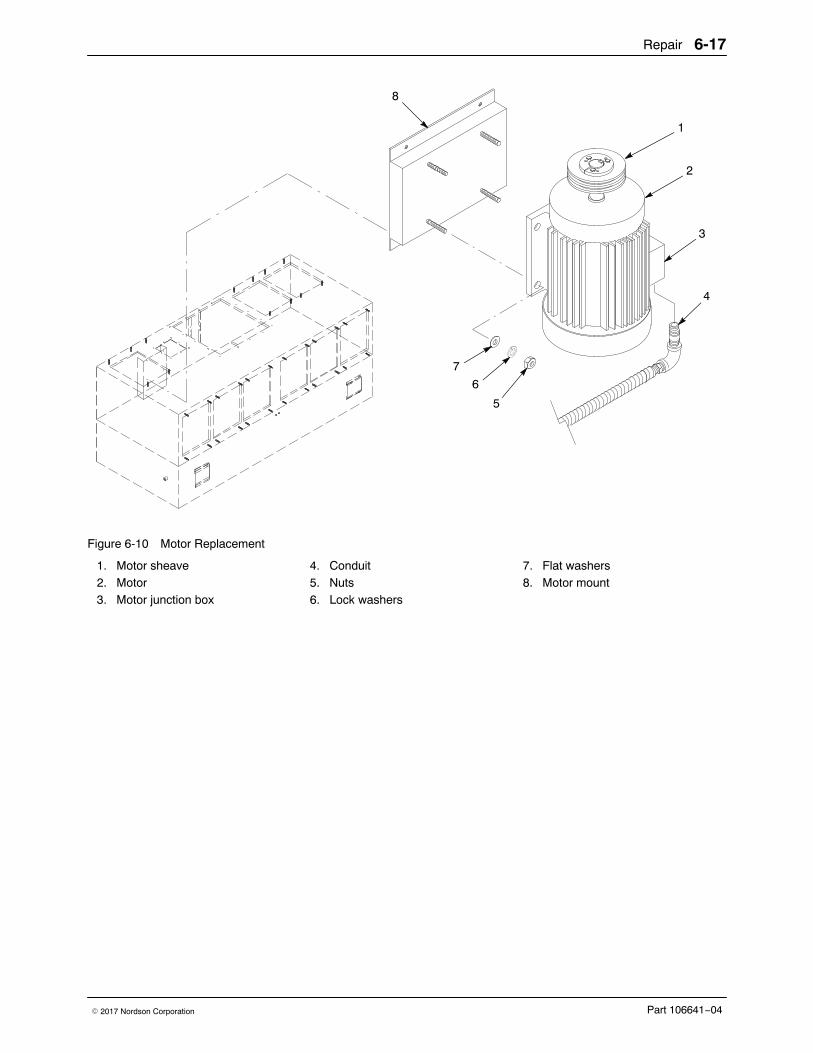
Repair 6-17
Part 106641−04� 2017 Nordson Corporation
1
3
5
4
8
2
6
7
Figure 6-10 Motor Replacement
1. Motor sheave2. Motor3. Motor junction box
4. Conduit5. Nuts6. Lock washers
7. Flat washers8. Motor mount
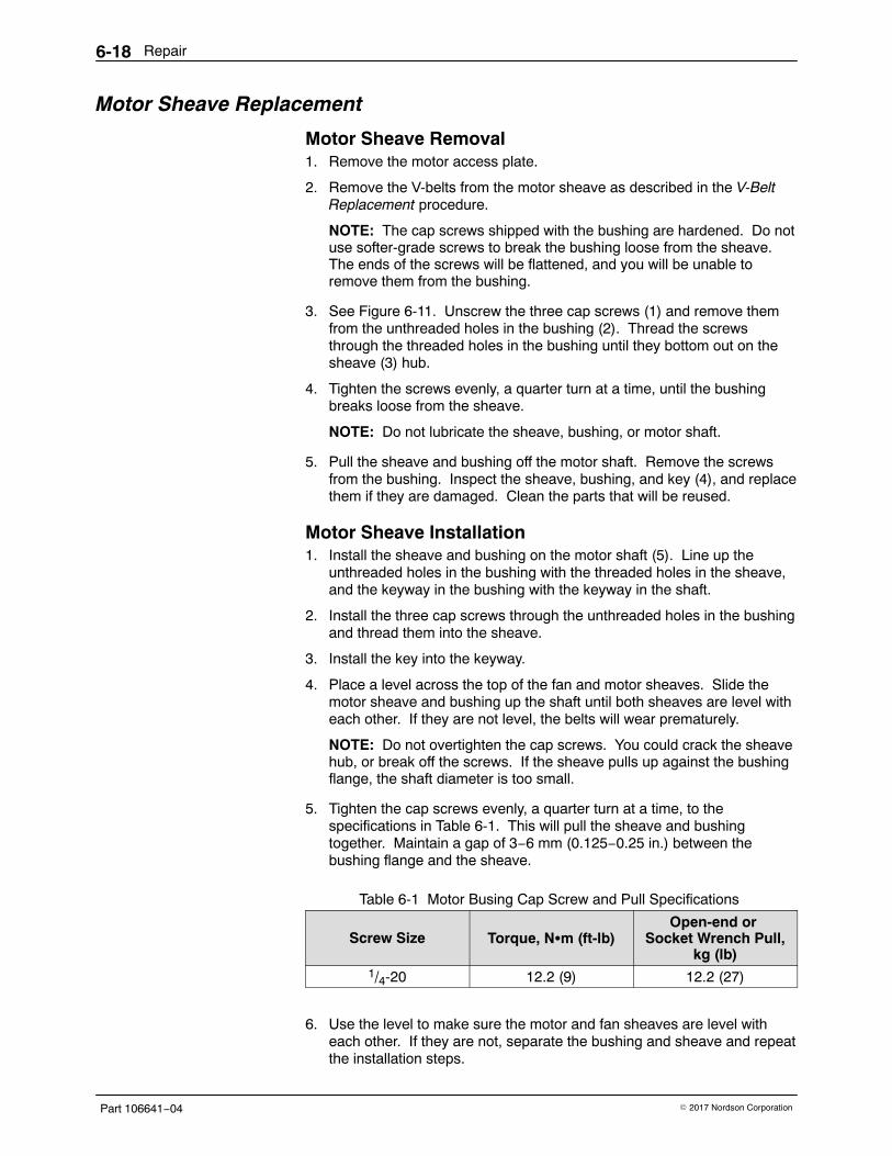
Repair6-18
Part 106641−04 � 2017 Nordson Corporation
Motor Sheave Replacement
Motor Sheave Removal 1. Remove the motor access plate.
2. Remove the V-belts from the motor sheave as described in the V-BeltReplacement procedure.
NOTE: The cap screws shipped with the bushing are hardened. Do notuse softer-grade screws to break the bushing loose from the sheave.The ends of the screws will be flattened, and you will be unable toremove them from the bushing.
3. See Figure 6-11. Unscrew the three cap screws (1) and remove themfrom the unthreaded holes in the bushing (2). Thread the screwsthrough the threaded holes in the bushing until they bottom out on thesheave (3) hub.
4. Tighten the screws evenly, a quarter turn at a time, until the bushingbreaks loose from the sheave.
NOTE: Do not lubricate the sheave, bushing, or motor shaft.
5. Pull the sheave and bushing off the motor shaft. Remove the screwsfrom the bushing. Inspect the sheave, bushing, and key (4), and replacethem if they are damaged. Clean the parts that will be reused.
Motor Sheave Installation 1. Install the sheave and bushing on the motor shaft (5). Line up the
unthreaded holes in the bushing with the threaded holes in the sheave,and the keyway in the bushing with the keyway in the shaft.
2. Install the three cap screws through the unthreaded holes in the bushingand thread them into the sheave.
3. Install the key into the keyway.
4. Place a level across the top of the fan and motor sheaves. Slide themotor sheave and bushing up the shaft until both sheaves are level witheach other. If they are not level, the belts will wear prematurely.
NOTE: Do not overtighten the cap screws. You could crack the sheavehub, or break off the screws. If the sheave pulls up against the bushingflange, the shaft diameter is too small.
5. Tighten the cap screws evenly, a quarter turn at a time, to thespecifications in Table 6-1. This will pull the sheave and bushingtogether. Maintain a gap of 3−6 mm (0.125−0.25 in.) between thebushing flange and the sheave.
Table 6-1 Motor Busing Cap Screw and Pull Specifications
Screw Size Torque, N�m (ft-lb)Open-end or
Socket Wrench Pull,kg (lb)
1/4-20 12.2 (9) 12.2 (27)
6. Use the level to make sure the motor and fan sheaves are level witheach other. If they are not, separate the bushing and sheave and repeatthe installation steps.
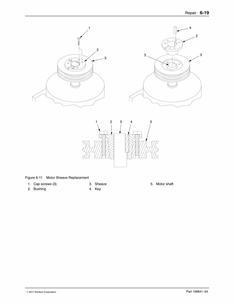
Repair 6-19
Part 106641−04� 2017 Nordson Corporation
1 4
3
2
2
3
5
5
1 2 4 3
Figure 6-11 Motor Sheave Replacement
1. Cap screws (3)2. Bushing
3. Sheave4. Key
5. Motor shaft
Repair6-20
Part 106641−04 � 2017 Nordson Corporation
Fan Replacement
WARNING: Before performing the following procedures, shut off electricalpower at the system electrical panel. Lock and tag the disconnect switch.
Fan Removal 1. Remove the color module from under the fan section as described in the
Operation section.
2. See Figure 6-13. Remove the screws (21), washers (19, 20),retainers (18), and the inlet cone (22) from the fan section.
3. Loosen the key and shaft set screws in the hub of the fan (16).
4. Block up the fan. Remove the screw (14) and retainer washer (15) fromthe bottom of the shaft (5).
5. Remove the blocks, fan, and key (8) from the fan section.
Fan Installation 1. Install the new fan on the shaft, line up the keyways, and install the key.
Slide blocks between the fan and the floor of the fan section to hold thefan up.
2. Tighten the key set screw in the fan hub to hold the fan in place. Torquethe set screw to the specification listed in Table 6-2.
Table 6-2 Fan Wheel Torque Specifications
Booth Model Torque Specification
2001 3.5 N�m (30.9 in.-lb)
2002 3.5 N�m (30.9 in.-lb)
2003 8.5 N�m (75.6 in.-lb)
3. Install the retainer washer and screw it onto the end of the shaft.Remove the blocks.
4. Install the inlet cone in the fan section with the retainers, washers, andscrews. Do not tighten the screws.
NOTE: You will tighten the screws during the Fan Adjustmentprocedure.
Fan Adjustment 1. See Figure 6-12 and refer to Table 6-4. Adjust the height of the fan on
the shaft. The bottom of the fan should sit inside the cone (overlap)3−6 mm (0.125−0.25 in.). Tighten the shaft set screw in the fan hub.
2. Adjust the inlet cone so the gap between the fan and the cone is thesame all the way around. Use your finger to check the gap.
3. Tighten the screws securing the inlet cone to the fan section andrecheck the gap. Rotate the fan and make sure it does not rub againstthe cone.
4. Start the exhaust fan and make sure the fan does not rub against theinlet cone.
Repair 6-21
Part 106641−04� 2017 Nordson Corporation
Fan Sheave Replacement WARNING: Before performing the following procedures, shut off electricalpower at the system electrical panel. Lock and tag the disconnect switch.
Fan Sheave Removal1. Remove the V-belts, as described in V-Belt Replacement, from the fan
sheave.
NOTE: The cap screws shipped with the bushing are hardened. Do notuse softer-grade screws to break the bushing loose from the sheave.The ends of the screws will be flattened, and you will be unable toremove them from the bushing.
2. See Figure 6-13. Unscrew the three cap screws (1) and remove themfrom the unthreaded holes in the bushing (3). Thread the screwsthrough the threaded holes in the bushing until they bottom out on thesheave (4) hub.
3. Tighten the screws evenly, a quarter turn at a time, until the bushingbreaks loose from the sheave.
4. Pull the sheave, bushing, and key (2) off the fan shaft. Remove thescrews from the bushing.
NOTE: Do not lubricate the sheave, bushing, or fan shaft.
5. Inspect the sheave, bushing, and key. Replace them if they aredamaged. Clean the parts that will be reused.
Fan Sheave Installation 1. Install the sheave and bushing on the fan shaft. Line up the unthreaded
holes in the bushing with the threaded holes in the sheave, and thekeyway in the bushing with the keyway in the shaft.
2. Install the three cap screws through the unthreaded holes in the bushingand thread them into the sheave. Do not tighten the screws.
3. Install the key into the keyway.
4. Place a level across the top of the fan and motor sheaves. Slide the fansheave and bushing up the shaft until both sheaves are level with eachother. If they are not level, the belts will wear prematurely.
NOTE: Do not overtighten the screws. You could crack the sheave hub, orbreak off the screws. If the sheave pulls up against the bushing flange, theshaft diameter is too small.
5. Tighten the cap screws evenly, a quarter turn at a time, to force thetapered bushing into the sheave. Tighten the screws as specified inTable 6-3. Maintain a gap of 3−6 mm (0.125−0.25 in.) between thebushing flange and the sheave. See Figure 6-12 and Table 6-4.
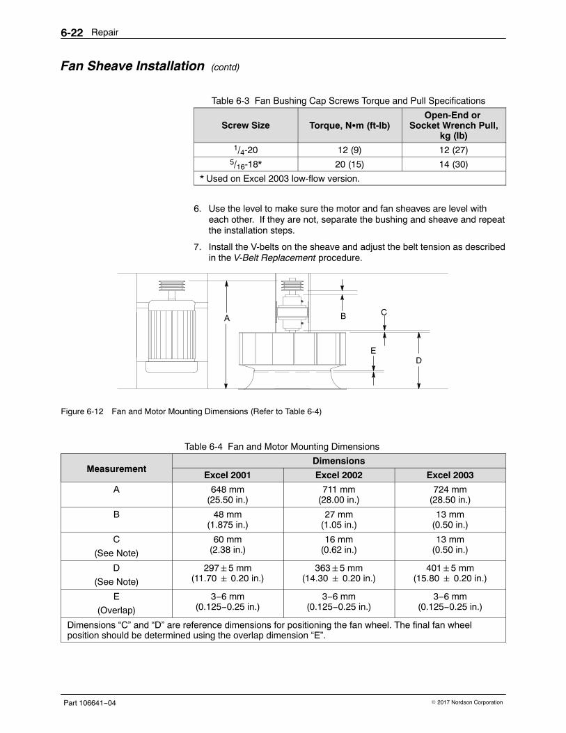
Repair6-22
Part 106641−04 � 2017 Nordson Corporation
Fan Sheave Installation (contd)
Table 6-3 Fan Bushing Cap Screws Torque and Pull Specifications
Screw Size Torque, N�m (ft-lb)Open-End or
Socket Wrench Pull,kg (lb)
1/4-20 12 (9) 12 (27)5/16-18* 20 (15) 14 (30)
* Used on Excel 2003 low-flow version.
6. Use the level to make sure the motor and fan sheaves are level witheach other. If they are not, separate the bushing and sheave and repeatthe installation steps.
7. Install the V-belts on the sheave and adjust the belt tension as describedin the V-Belt Replacement procedure.
A
D
CB
E
Figure 6-12 Fan and Motor Mounting Dimensions (Refer to Table 6-4)
Table 6-4 Fan and Motor Mounting Dimensions
MeasurementDimensions
Excel 2001 Excel 2002 Excel 2003
A 648 mm(25.50 in.)
711 mm(28.00 in.)
724 mm(28.50 in.)
B 48 mm(1.875 in.)
27 mm(1.05 in.)
13 mm(0.50 in.)
C
(See Note)
60 mm(2.38 in.)
16 mm(0.62 in.)
13 mm(0.50 in.)
D
(See Note)
297�5 mm(11.70 � 0.20 in.)
363�5 mm(14.30 � 0.20 in.)
401�5 mm(15.80 � 0.20 in.)
E
(Overlap)
3−6 mm(0.125−0.25 in.)
3−6 mm(0.125−0.25 in.)
3−6 mm(0.125−0.25 in.)
Dimensions “C” and “D” are reference dimensions for positioning the fan wheel. The final fan wheelposition should be determined using the overlap dimension “E”.
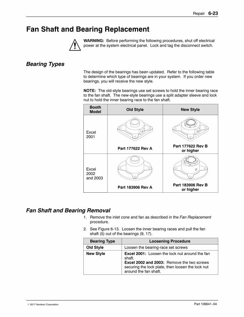
Repair 6-23
Part 106641−04� 2017 Nordson Corporation
Fan Shaft and Bearing Replacement WARNING: Before performing the following procedures, shut off electricalpower at the system electrical panel. Lock and tag the disconnect switch.
Bearing Types The design of the bearings has been updated. Refer to the following tableto determine which type of bearings are in your system. If you order newbearings, you will receive the new style.
NOTE: The old-style bearings use set screws to hold the inner bearing raceto the fan shaft. The new-style bearings use a split adapter sleeve and locknut to hold the inner bearing race to the fan shaft.
BoothModel Old Style New Style
Excel2001
Part 177622 Rev A Part 177622 Rev Bor higher
Excel2002and 2003
Part 183906 Rev A Part 183906 Rev Bor higher
Fan Shaft and Bearing Removal 1. Remove the inlet cone and fan as described in the Fan Replacement
procedure.
2. See Figure 6-13. Loosen the inner bearing races and pull the fanshaft (5) out of the bearings (9, 17).
Bearing Type Loosening Procedure
Old Style Loosen the bearing-race set screws
New Style Excel 2001: Loosen the lock nut around the fanshaft.Excel 2002 and 2003: Remove the two screwssecuring the lock plate, then loosen the lock nutaround the fan shaft.
Repair6-24
Part 106641−04 � 2017 Nordson Corporation
Fan Shaft and Bearing Removal (contd)
3. If you are replacing the shaft, remove the fan sheave (4), bushing (3),and key (2) from the shaft as described in the Fan Sheave Replacementprocedure.
4. If you are replacing the bearings, disconnect the tubing from the tubefittings (10). Remove the screws (6), washers (7, 12), and nuts (13)securing the bearings to the support (11).
NOTE: Replace the bearings with the ones listed in the Parts sectiononly. Do not use unapproved bearings.
5. Remove the tube fittings from the old bearings and install them in thenew bearings in place of the grease fittings.
Fan Shaft and Bearing Installation See Figure 6-13.
Excel 2001 New-Style Bearings Only: Install 1/16-in. shims between themounting surface and the expansion bearing (17). Do not install shims onthe non-expansion bearing (9).
1. Install the new bearings on the supports with the screws (6), washers (7, 12), and nuts (13). Do not tighten the screws. Connect thetubing to the tube fittings (10).
2. Apply a coating of light oil to the shaft (5) where the bearings will bemounted.
NOTE: Excel 2002 and 2003 New-Style Bearings Only: Place the lockplate (See Figure 6-15 (1)) on each bearing, but do not install the screwsyet.
3. Install the shaft through the bearings. If you have trouble getting theshaft through the bearings,
All New-Style Bearings: Loosen the lock nut.
All Old-Style Bearings: Try one or more of the steps below:
� Loosen the bearing-race set screws.
� Clean the shaft and ID of the bearing inner-race with a clean clothand a small amount of penetrating oil. Do not get any oil inside thebearing races. The penetrating oil will dissolve the grease needed tolubricate the bearings.
� Gently drive the shaft through the bearings with a soft-faced malletor a hammer. If you use a hammer, place a block of wood on theend of the shaft and strike the wood, not the shaft.
� Chill the shaft in a freezer or with dry ice and install it through thebearings while it is cold.
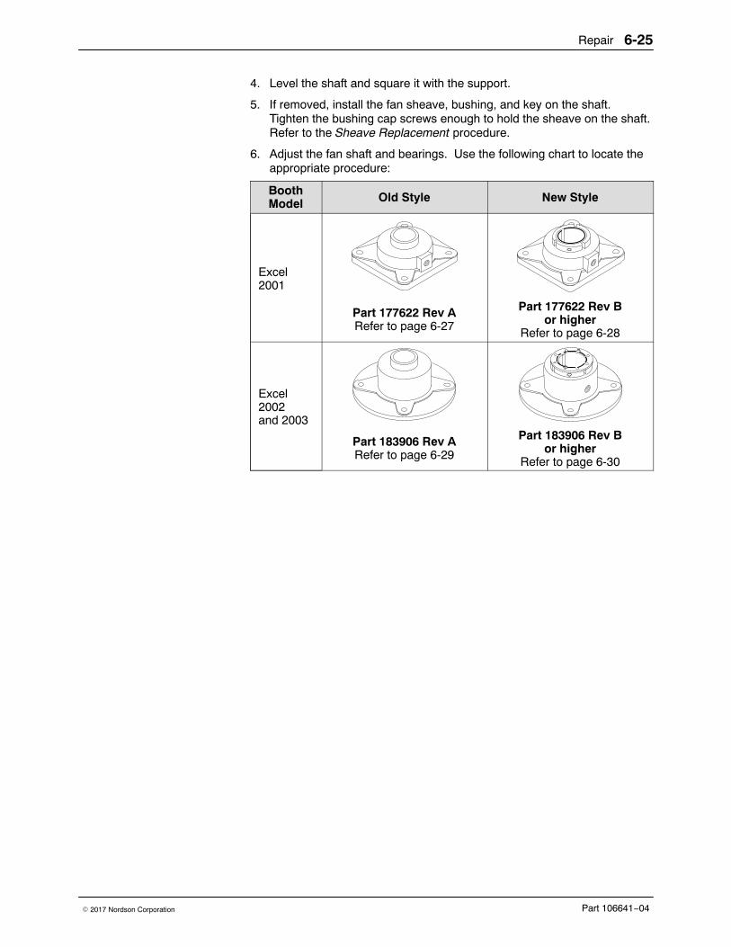
Repair 6-25
Part 106641−04� 2017 Nordson Corporation
4. Level the shaft and square it with the support.
5. If removed, install the fan sheave, bushing, and key on the shaft.Tighten the bushing cap screws enough to hold the sheave on the shaft.Refer to the Sheave Replacement procedure.
6. Adjust the fan shaft and bearings. Use the following chart to locate theappropriate procedure:
BoothModel Old Style New Style
Excel2001
Part 177622 Rev ARefer to page 6-27
Part 177622 Rev Bor higher
Refer to page 6-28
Excel2002and 2003
Part 183906 Rev ARefer to page 6-29
Part 183906 Rev Bor higher
Refer to page 6-30
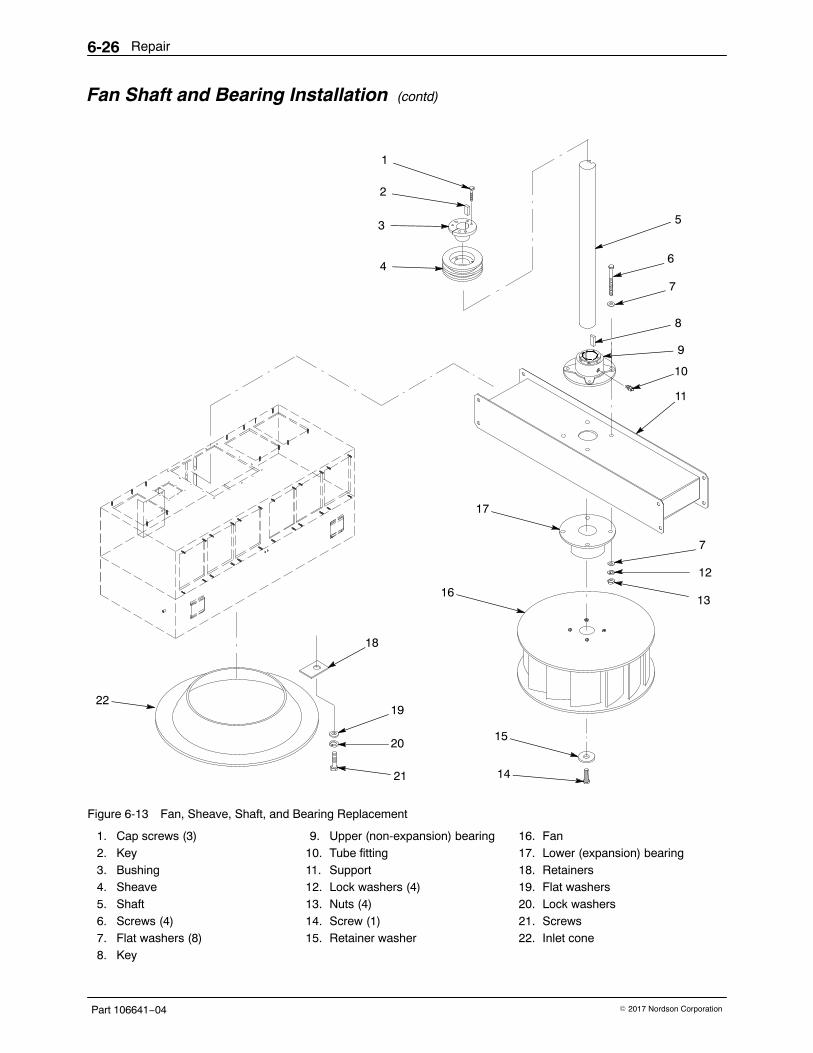
Repair6-26
Part 106641−04 � 2017 Nordson Corporation
Fan Shaft and Bearing Installation (contd)
4
1
5
6
8
10
11
12
17
16
15
14
18
20
22
3
2
7
7
13
21
19
9
Figure 6-13 Fan, Sheave, Shaft, and Bearing Replacement
1. Cap screws (3)2. Key3. Bushing4. Sheave5. Shaft6. Screws (4)7. Flat washers (8)8. Key
9. Upper (non-expansion) bearing10. Tube fitting11. Support12. Lock washers (4)13. Nuts (4)14. Screw (1)15. Retainer washer
16. Fan17. Lower (expansion) bearing18. Retainers19. Flat washers20. Lock washers21. Screws22. Inlet cone
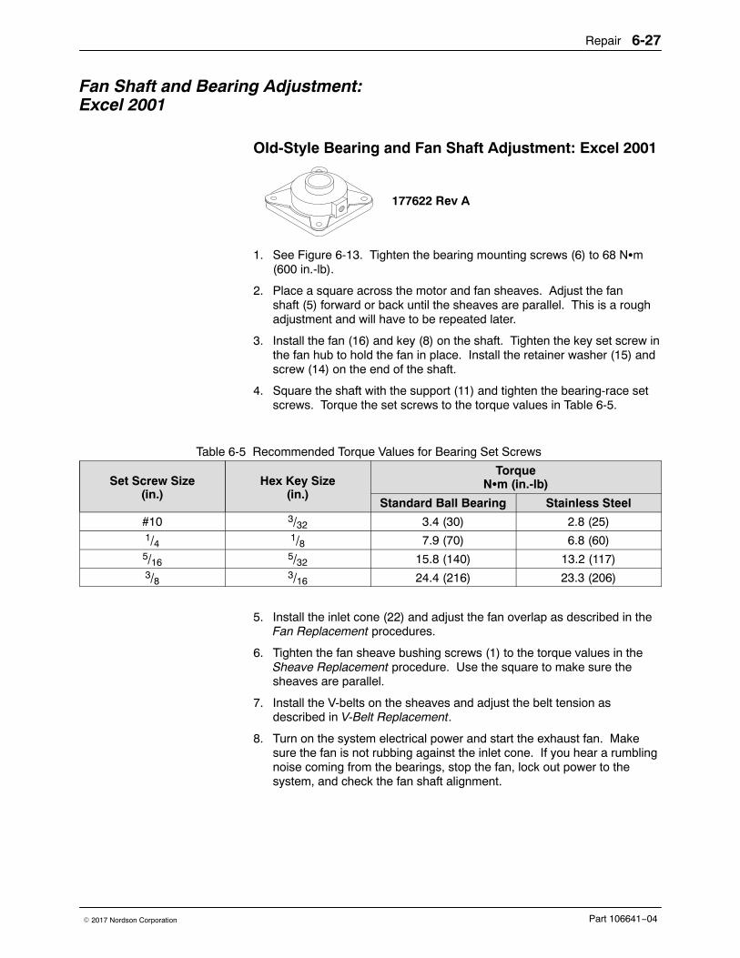
Repair 6-27
Part 106641−04� 2017 Nordson Corporation
Fan Shaft and Bearing Adjustment:Excel 2001
Old-Style Bearing and Fan Shaft Adjustment: Excel 2001
177622 Rev A
1. See Figure 6-13. Tighten the bearing mounting screws (6) to 68 N�m(600 in.-lb).
2. Place a square across the motor and fan sheaves. Adjust the fanshaft (5) forward or back until the sheaves are parallel. This is a roughadjustment and will have to be repeated later.
3. Install the fan (16) and key (8) on the shaft. Tighten the key set screw inthe fan hub to hold the fan in place. Install the retainer washer (15) andscrew (14) on the end of the shaft.
4. Square the shaft with the support (11) and tighten the bearing-race setscrews. Torque the set screws to the torque values in Table 6-5.
Table 6-5 Recommended Torque Values for Bearing Set Screws
Set Screw Size(in.)
Hex Key Size(in.)
TorqueN�m (in.-lb)
Standard Ball Bearing Stainless Steel
#10 3/32 3.4 (30) 2.8 (25)1/4 1/8 7.9 (70) 6.8 (60)5/16
5/32 15.8 (140) 13.2 (117)3/8 3/16 24.4 (216) 23.3 (206)
5. Install the inlet cone (22) and adjust the fan overlap as described in theFan Replacement procedures.
6. Tighten the fan sheave bushing screws (1) to the torque values in theSheave Replacement procedure. Use the square to make sure thesheaves are parallel.
7. Install the V-belts on the sheaves and adjust the belt tension asdescribed in V-Belt Replacement.
8. Turn on the system electrical power and start the exhaust fan. Makesure the fan is not rubbing against the inlet cone. If you hear a rumblingnoise coming from the bearings, stop the fan, lock out power to thesystem, and check the fan shaft alignment.
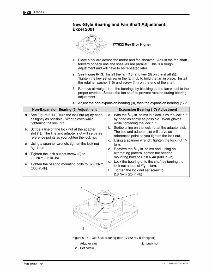
Repair6-28
Part 106641−04 � 2017 Nordson Corporation
New-Style Bearing and Fan Shaft Adjustment: Excel 2001
177622 Rev B or Higher
1. Place a square across the motor and fan sheaves. Adjust the fan shaftforward or back until the sheaves are parallel. This is a roughadjustment and will have to be repeated later.
2. See Figure 6-13. Install the fan (16) and key (8) on the shaft (5).Tighten the key set screw in the fan hub to hold the fan in place. Installthe retainer washer (15) and screw (14) on the end of the shaft.
3. Remove all weight from the bearings by blocking up the fan wheel to theproper overlap. Secure the fan shaft to prevent rotation during bearingadjustment.
4. Adjust the non-expansion bearing (9), then the expansion bearing (17):
Non-Expansion Bearing (9) Adjustment Expansion Bearing (17) Adjustment
a. See Figure 6-14. Turn the lock nut (3) by handas tightly as possible. Wear gloves whiletightening the lock nut.
b. Scribe a line on the lock nut at the adapterslot (1). The line and adapter slot will serve asreference points as you tighten the lock nut.
c. Using a spanner wrench, tighten the lock nut2/3−1 turn.
d. Tighten the lock nut set screw (2) to 2.8 N•m (25 in.-lb).
e. Tighten the bearing mounting bolts to 67.8 N•m(600 in.-lb).
a. With the 1/16-in. shims in place, turn the lock nutby hand as tightly as possible. Wear gloveswhile tightening the lock nut.
b. Scribe a line on the lock nut at the adapter slot.The line and adapter slot will serve asreferences point as you tighten the lock nut.
c. Using a spanner wrench, tighten the lock nut 1/8turn.
d. Remove the 1/16-in. shims and, using analternating pattern, tighten the bearingmounting bolts to 67.8 N•m (600 in.-lb).
e. Lock the bearing onto the shaft by turning thelock nut a total of 2/3−1 turn.
f. Tighten the lock nut set screw to2.8 N•m (25 in.-lb).
1
2
3
Figure 6-14 Old-Style Bearing (part 17762 rev B or higher)
1. Adapter slot2. Set screw
3. Lock nut
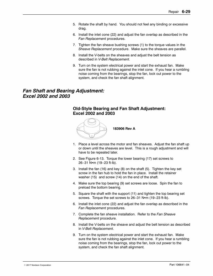
Repair 6-29
Part 106641−04� 2017 Nordson Corporation
5. Rotate the shaft by hand. You should not feel any binding or excessivedrag.
6. Install the inlet cone (22) and adjust the fan overlap as described in theFan Replacement procedures.
7. Tighten the fan sheave bushing screws (1) to the torque values in theSheave Replacement procedure. Make sure the sheaves are parallel.
8. Install the V-belts on the sheaves and adjust the belt tension asdescribed in V-Belt Replacement.
9. Turn on the system electrical power and start the exhaust fan. Makesure the fan is not rubbing against the inlet cone. If you hear a rumblingnoise coming from the bearings, stop the fan, lock out power to thesystem, and check the fan shaft alignment.
Fan Shaft and Bearing Adjustment:Excel 2002 and 2003
Old-Style Bearing and Fan Shaft Adjustment:Excel 2002 and 2003
183906 Rev A
1. Place a level across the motor and fan sheaves. Adjust the fan shaft upor down until the sheaves are level. This is a rough adjustment and willhave to be repeated later.
2. See Figure 6-13. Torque the lower bearing (17) set screws to26−31 N�m (19−23 ft-lb).
3. Install the fan (16) and key (8) on the shaft (5). Tighten the key setscrew in the fan hub to hold the fan in place. Install the retainerwasher (15) and screw (14) on the end of the shaft.
4. Make sure the top bearing (9) set screws are loose. Spin the fan topreload the bottom bearing.
5. Square the shaft with the support (11) and tighten the top bearing setscrews. Torque the set screws to 26−31 N�m (19−23 ft-lb).
6. Install the inlet cone (22) and adjust the fan overlap as described in theFan Replacement procedures.
7. Complete the fan sheave installation. Refer to the Fan SheaveReplacement procedure.
8. Install the V-belts on the sheave and adjust the belt tension as describedin V-Belt Replacement.
9. Turn on the system electrical power and start the exhaust fan. Makesure the fan is not rubbing against the inlet cone. If you hear a rumblingnoise coming from the bearings, stop the fan, lock out power to thesystem, and check the fan shaft alignment.
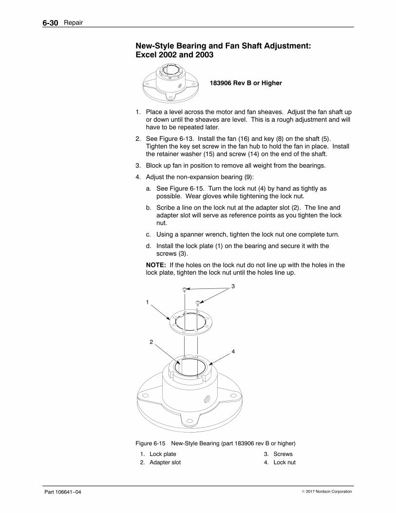
Repair6-30
Part 106641−04 � 2017 Nordson Corporation
New-Style Bearing and Fan Shaft Adjustment:Excel 2002 and 2003
183906 Rev B or Higher
1. Place a level across the motor and fan sheaves. Adjust the fan shaft upor down until the sheaves are level. This is a rough adjustment and willhave to be repeated later.
2. See Figure 6-13. Install the fan (16) and key (8) on the shaft (5).Tighten the key set screw in the fan hub to hold the fan in place. Installthe retainer washer (15) and screw (14) on the end of the shaft.
3. Block up fan in position to remove all weight from the bearings.
4. Adjust the non-expansion bearing (9):
a. See Figure 6-15. Turn the lock nut (4) by hand as tightly aspossible. Wear gloves while tightening the lock nut.
b. Scribe a line on the lock nut at the adapter slot (2). The line andadapter slot will serve as reference points as you tighten the locknut.
c. Using a spanner wrench, tighten the lock nut one complete turn.
d. Install the lock plate (1) on the bearing and secure it with thescrews (3).
NOTE: If the holes on the lock nut do not line up with the holes in thelock plate, tighten the lock nut until the holes line up.
2
4
1
3
Figure 6-15 New-Style Bearing (part 183906 rev B or higher)
1. Lock plate2. Adapter slot
3. Screws4. Lock nut
Repair 6-31
Part 106641−04� 2017 Nordson Corporation
5. See Figure 6-13. Convert the other bearing to a expansion bearing (17):
a. Remove the snap ring (on the side of the bearing opposite the lockplate) from the innermost groove on the bearing.
b. Install the snap ring into the outermost groove on the bearing.
NOTE: When you install the expansion bearing, make sure its innerbearing race is pushed as far as possible toward the non-expansionbearing (9).
6. Install the expansion bearing (17) using steps 4a−4d.
7. Tighten the bearing mounting bolts to 67.8 N•m (600 in.-lb).
8. Rotate the shaft by hand. You should not feel any binding or excessivedrag.
9. Install the inlet cone (22) and adjust the fan overlap as described in theFan Replacement procedures.
10. Tighten the fan sheave bushing screws (1) to the torque values in theSheave Replacement procedure. Make sure the sheaves are parallel.
11. Install the V-belts on the sheaves and adjust the belt tension asdescribed in V-Belt Replacement.
12. Turn on the system electrical power and start the exhaust fan. Makesure the fan is not rubbing against the inlet cone. If you hear a rumblingnoise coming from the bearings, stop the fan, lock out power to thesystem, and check the fan shaft alignment.
Repair6-32
Part 106641−04 � 2017 Nordson Corporation
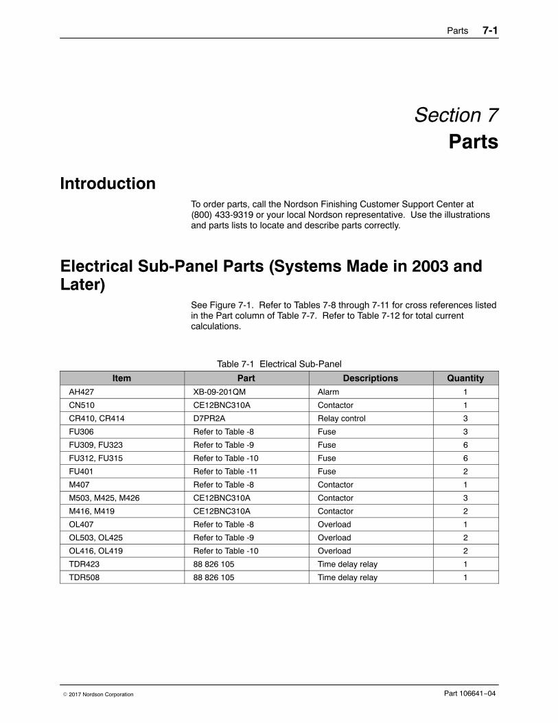
Parts 7-1
Part 106641−04� 2017 Nordson Corporation
Section 7Parts
Introduction To order parts, call the Nordson Finishing Customer Support Center at(800) 433-9319 or your local Nordson representative. Use the illustrationsand parts lists to locate and describe parts correctly.
Electrical Sub-Panel Parts (Systems Made in 2003 andLater)
See Figure 7-1. Refer to Tables 7-8 through 7-11 for cross references listedin the Part column of Table 7-7. Refer to Table 7-12 for total currentcalculations.
Table 7-1 Electrical Sub-Panel
Item Part Descriptions QuantityAH427 XB-09-201QM Alarm 1
CN510 CE12BNC310A Contactor 1
CR410, CR414 D7PR2A Relay control 3
FU306 Refer to Table -8 Fuse 3
FU309, FU323 Refer to Table -9 Fuse 6
FU312, FU315 Refer to Table -10 Fuse 6
FU401 Refer to Table -11 Fuse 2
M407 Refer to Table -8 Contactor 1
M503, M425, M426 CE12BNC310A Contactor 3
M416, M419 CE12BNC310A Contactor 2
OL407 Refer to Table -8 Overload 1
OL503, OL425 Refer to Table -9 Overload 2
OL416, OL419 Refer to Table -10 Overload 2
TDR423 88 826 105 Time delay relay 1
TDR508 88 826 105 Time delay relay 1
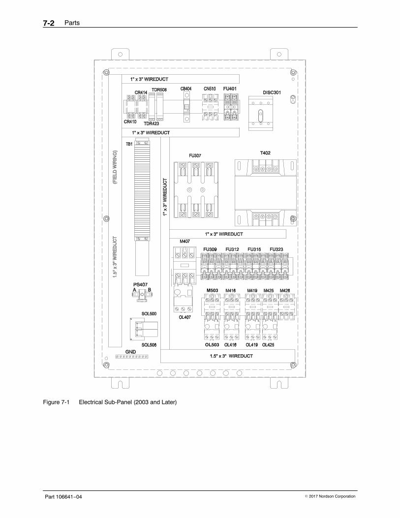
Parts7-2
Part 106641−04 � 2017 Nordson Corporation
M503
OL503
Figure 7-1 Electrical Sub-Panel (2003 and Later)
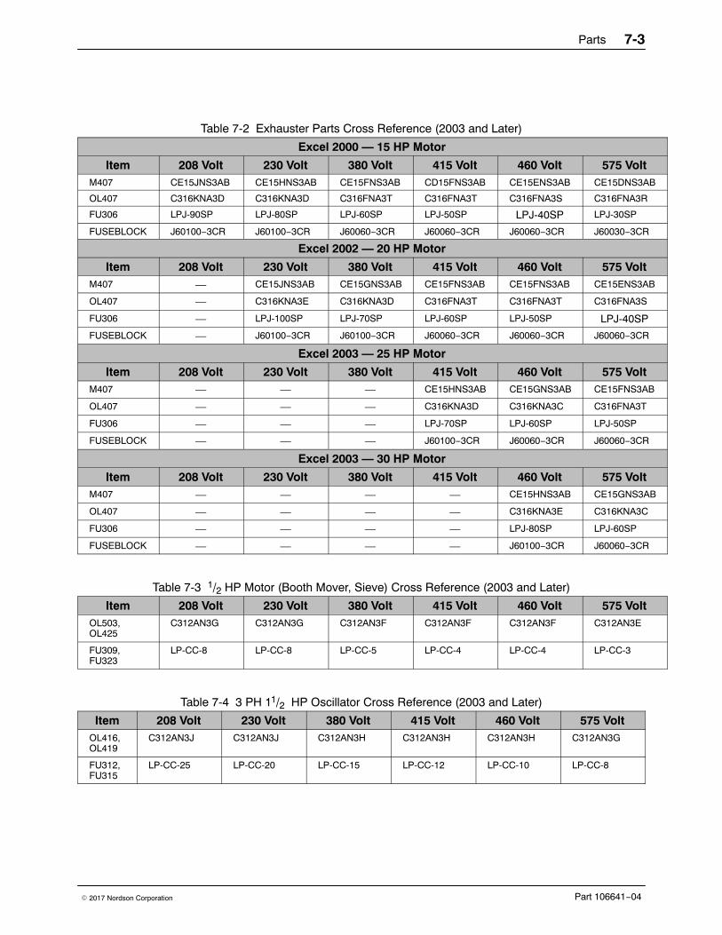
Parts 7-3
Part 106641−04� 2017 Nordson Corporation
Table 7-2 Exhauster Parts Cross Reference (2003 and Later)
Excel 2000 — 15 HP Motor
Item 208 Volt 230 Volt 380 Volt 415 Volt 460 Volt 575 VoltM407 CE15JNS3AB CE15HNS3AB CE15FNS3AB CD15FNS3AB CE15ENS3AB CE15DNS3AB
OL407 C316KNA3D C316KNA3D C316FNA3T C316FNA3T C316FNA3S C316FNA3R
FU306 LPJ-90SP LPJ-80SP LPJ-60SP LPJ-50SP LPJ-40SP LPJ-30SP
FUSEBLOCK J60100−3CR J60100−3CR J60060−3CR J60060−3CR J60060−3CR J60030−3CR
Excel 2002 — 20 HP Motor
Item 208 Volt 230 Volt 380 Volt 415 Volt 460 Volt 575 VoltM407 — CE15JNS3AB CE15GNS3AB CE15FNS3AB CE15FNS3AB CE15ENS3AB
OL407 — C316KNA3E C316KNA3D C316FNA3T C316FNA3T C316FNA3S
FU306 — LPJ-100SP LPJ-70SP LPJ-60SP LPJ-50SP LPJ-40SP
FUSEBLOCK — J60100−3CR J60100−3CR J60060−3CR J60060−3CR J60060−3CR
Excel 2003 — 25 HP Motor
Item 208 Volt 230 Volt 380 Volt 415 Volt 460 Volt 575 VoltM407 — — — CE15HNS3AB CE15GNS3AB CE15FNS3AB
OL407 — — — C316KNA3D C316KNA3C C316FNA3T
FU306 — — — LPJ-70SP LPJ-60SP LPJ-50SP
FUSEBLOCK — — — J60100−3CR J60060−3CR J60060−3CR
Excel 2003 — 30 HP Motor
Item 208 Volt 230 Volt 380 Volt 415 Volt 460 Volt 575 VoltM407 — — — — CE15HNS3AB CE15GNS3AB
OL407 — — — — C316KNA3E C316KNA3C
FU306 — — — — LPJ-80SP LPJ-60SP
FUSEBLOCK — — — — J60100−3CR J60060−3CR
Table 7-3 1/2 HP Motor (Booth Mover, Sieve) Cross Reference (2003 and Later)
Item 208 Volt 230 Volt 380 Volt 415 Volt 460 Volt 575 VoltOL503, OL425
C312AN3G C312AN3G C312AN3F C312AN3F C312AN3F C312AN3E
FU309, FU323
LP-CC-8 LP-CC-8 LP-CC-5 LP-CC-4 LP-CC-4 LP-CC-3
Table 7-4 3 PH 11/2 HP Oscillator Cross Reference (2003 and Later)
Item 208 Volt 230 Volt 380 Volt 415 Volt 460 Volt 575 VoltOL416,OL419
C312AN3J C312AN3J C312AN3H C312AN3H C312AN3H C312AN3G
FU312,FU315
LP-CC-25 LP-CC-20 LP-CC-15 LP-CC-12 LP-CC-10 LP-CC-8
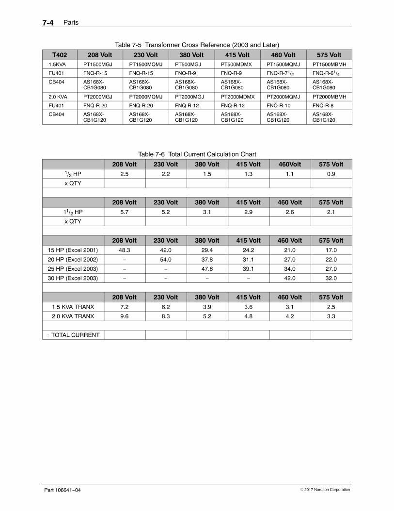
Parts7-4
Part 106641−04 � 2017 Nordson Corporation
Table 7-5 Transformer Cross Reference (2003 and Later)
T402 208 Volt 230 Volt 380 Volt 415 Volt 460 Volt 575 Volt1.5KVA PT1500MGJ PT1500MQMJ PT500MGJ PT500MDMX PT1500MQMJ PT1500MBMH
FU401 FNQ-R-15 FNQ-R-15 FNQ-R-9 FNQ-R-9 FNQ-R-71/2 FNQ-R-61/4
CB404 AS168X-CB1G080
AS168X-CB1G080
AS168X-CB1G080
AS168X-CB1G080
AS168X-CB1G080
AS168X-CB1G080
2.0 KVA PT2000MGJ PT2000MQMJ PT2000MGJ PT2000MDMX PT2000MQMJ PT2000MBMH
FU401 FNQ-R-20 FNQ-R-20 FNQ-R-12 FNQ-R-12 FNQ-R-10 FNQ-R-8
CB404 AS168X-CB1G120
AS168X-CB1G120
AS168X-CB1G120
AS168X-CB1G120
AS168X-CB1G120
AS168X-CB1G120
Table 7-6 Total Current Calculation Chart
208 Volt 230 Volt 380 Volt 415 Volt 460Volt 575 Volt1/2 HP 2.5 2.2 1.5 1.3 1.1 0.9
x QTY
208 Volt 230 Volt 380 Volt 415 Volt 460 Volt 575 Volt11/2 HP 5.7 5.2 3.1 2.9 2.6 2.1
x QTY
208 Volt 230 Volt 380 Volt 415 Volt 460 Volt 575 Volt15 HP (Excel 2001) 48.3 42.0 29.4 24.2 21.0 17.0
20 HP (Excel 2002) − 54.0 37.8 31.1 27.0 22.0
25 HP (Excel 2003) − − 47.6 39.1 34.0 27.0
30 HP (Excel 2003) − − − − 42.0 32.0
208 Volt 230 Volt 380 Volt 415 Volt 460 Volt 575 Volt1.5 KVA TRANX 7.2 6.2 3.9 3.6 3.1 2.5
2.0 KVA TRANX 9.6 8.3 5.2 4.8 4.2 3.3
= TOTAL CURRENT
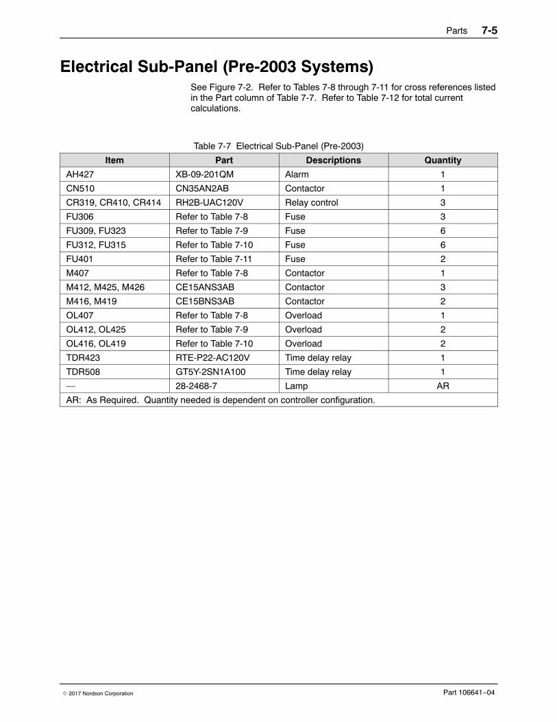
Parts 7-5
Part 106641−04� 2017 Nordson Corporation
Electrical Sub-Panel (Pre-2003 Systems) See Figure 7-2. Refer to Tables 7-8 through 7-11 for cross references listedin the Part column of Table 7-7. Refer to Table 7-12 for total currentcalculations.
Table 7-7 Electrical Sub-Panel (Pre-2003)
Item Part Descriptions Quantity
AH427 XB-09-201QM Alarm 1
CN510 CN35AN2AB Contactor 1
CR319, CR410, CR414 RH2B-UAC120V Relay control 3
FU306 Refer to Table 7-8 Fuse 3
FU309, FU323 Refer to Table 7-9 Fuse 6
FU312, FU315 Refer to Table 7-10 Fuse 6
FU401 Refer to Table 7-11 Fuse 2
M407 Refer to Table 7-8 Contactor 1
M412, M425, M426 CE15ANS3AB Contactor 3
M416, M419 CE15BNS3AB Contactor 2
OL407 Refer to Table 7-8 Overload 1
OL412, OL425 Refer to Table 7-9 Overload 2
OL416, OL419 Refer to Table 7-10 Overload 2
TDR423 RTE-P22-AC120V Time delay relay 1
TDR508 GT5Y-2SN1A100 Time delay relay 1
— 28-2468-7 Lamp AR
AR: As Required. Quantity needed is dependent on controller configuration.
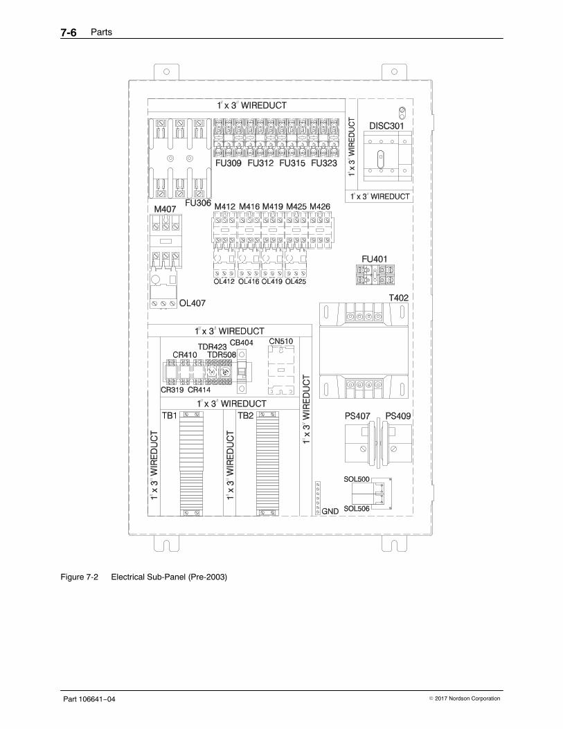
Parts7-6
Part 106641−04 � 2017 Nordson Corporation
Figure 7-2 Electrical Sub-Panel (Pre-2003)
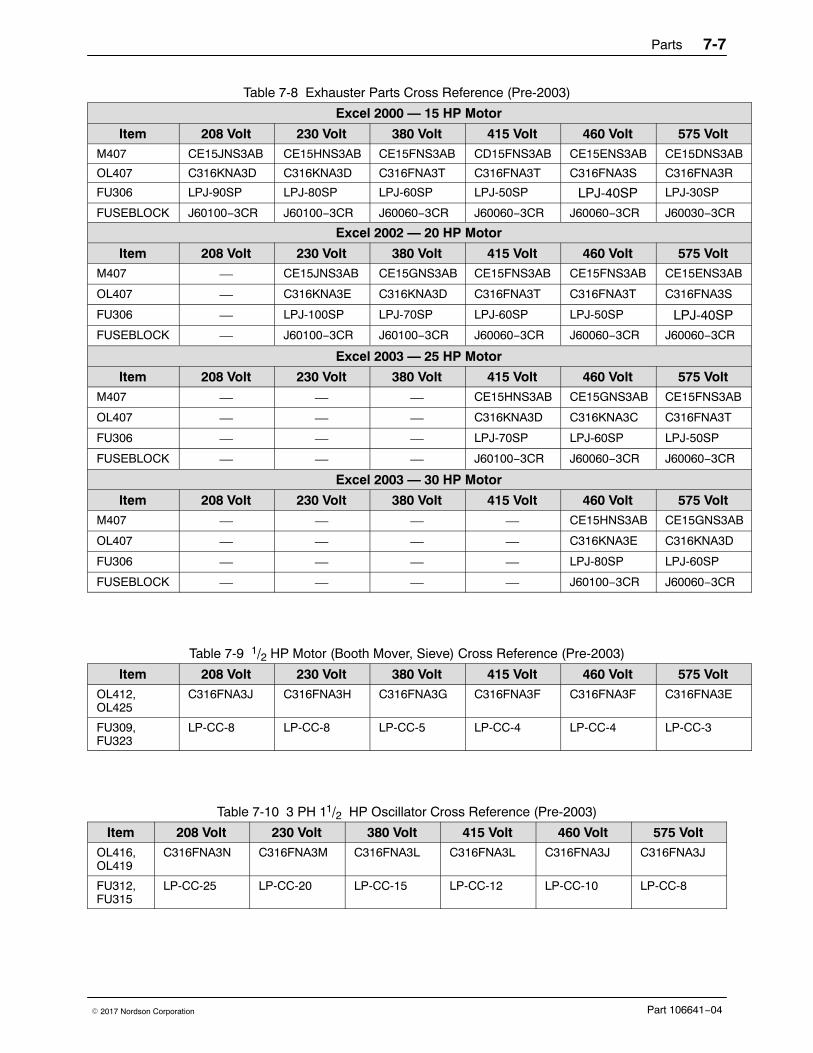
Parts 7-7
Part 106641−04� 2017 Nordson Corporation
Table 7-8 Exhauster Parts Cross Reference (Pre-2003)
Excel 2000 — 15 HP Motor
Item 208 Volt 230 Volt 380 Volt 415 Volt 460 Volt 575 VoltM407 CE15JNS3AB CE15HNS3AB CE15FNS3AB CD15FNS3AB CE15ENS3AB CE15DNS3AB
OL407 C316KNA3D C316KNA3D C316FNA3T C316FNA3T C316FNA3S C316FNA3R
FU306 LPJ-90SP LPJ-80SP LPJ-60SP LPJ-50SP LPJ-40SP LPJ-30SP
FUSEBLOCK J60100−3CR J60100−3CR J60060−3CR J60060−3CR J60060−3CR J60030−3CR
Excel 2002 — 20 HP Motor
Item 208 Volt 230 Volt 380 Volt 415 Volt 460 Volt 575 VoltM407 — CE15JNS3AB CE15GNS3AB CE15FNS3AB CE15FNS3AB CE15ENS3AB
OL407 — C316KNA3E C316KNA3D C316FNA3T C316FNA3T C316FNA3S
FU306 — LPJ-100SP LPJ-70SP LPJ-60SP LPJ-50SP LPJ-40SP
FUSEBLOCK — J60100−3CR J60100−3CR J60060−3CR J60060−3CR J60060−3CR
Excel 2003 — 25 HP Motor
Item 208 Volt 230 Volt 380 Volt 415 Volt 460 Volt 575 VoltM407 — — — CE15HNS3AB CE15GNS3AB CE15FNS3AB
OL407 — — — C316KNA3D C316KNA3C C316FNA3T
FU306 — — — LPJ-70SP LPJ-60SP LPJ-50SP
FUSEBLOCK — — — J60100−3CR J60060−3CR J60060−3CR
Excel 2003 — 30 HP Motor
Item 208 Volt 230 Volt 380 Volt 415 Volt 460 Volt 575 VoltM407 — — — — CE15HNS3AB CE15GNS3AB
OL407 — — — — C316KNA3E C316KNA3D
FU306 — — — — LPJ-80SP LPJ-60SP
FUSEBLOCK — — — — J60100−3CR J60060−3CR
Table 7-9 1/2 HP Motor (Booth Mover, Sieve) Cross Reference (Pre-2003)
Item 208 Volt 230 Volt 380 Volt 415 Volt 460 Volt 575 VoltOL412,OL425
C316FNA3J C316FNA3H C316FNA3G C316FNA3F C316FNA3F C316FNA3E
FU309,FU323
LP-CC-8 LP-CC-8 LP-CC-5 LP-CC-4 LP-CC-4 LP-CC-3
Table 7-10 3 PH 11/2 HP Oscillator Cross Reference (Pre-2003)
Item 208 Volt 230 Volt 380 Volt 415 Volt 460 Volt 575 VoltOL416,OL419
C316FNA3N C316FNA3M C316FNA3L C316FNA3L C316FNA3J C316FNA3J
FU312,FU315
LP-CC-25 LP-CC-20 LP-CC-15 LP-CC-12 LP-CC-10 LP-CC-8
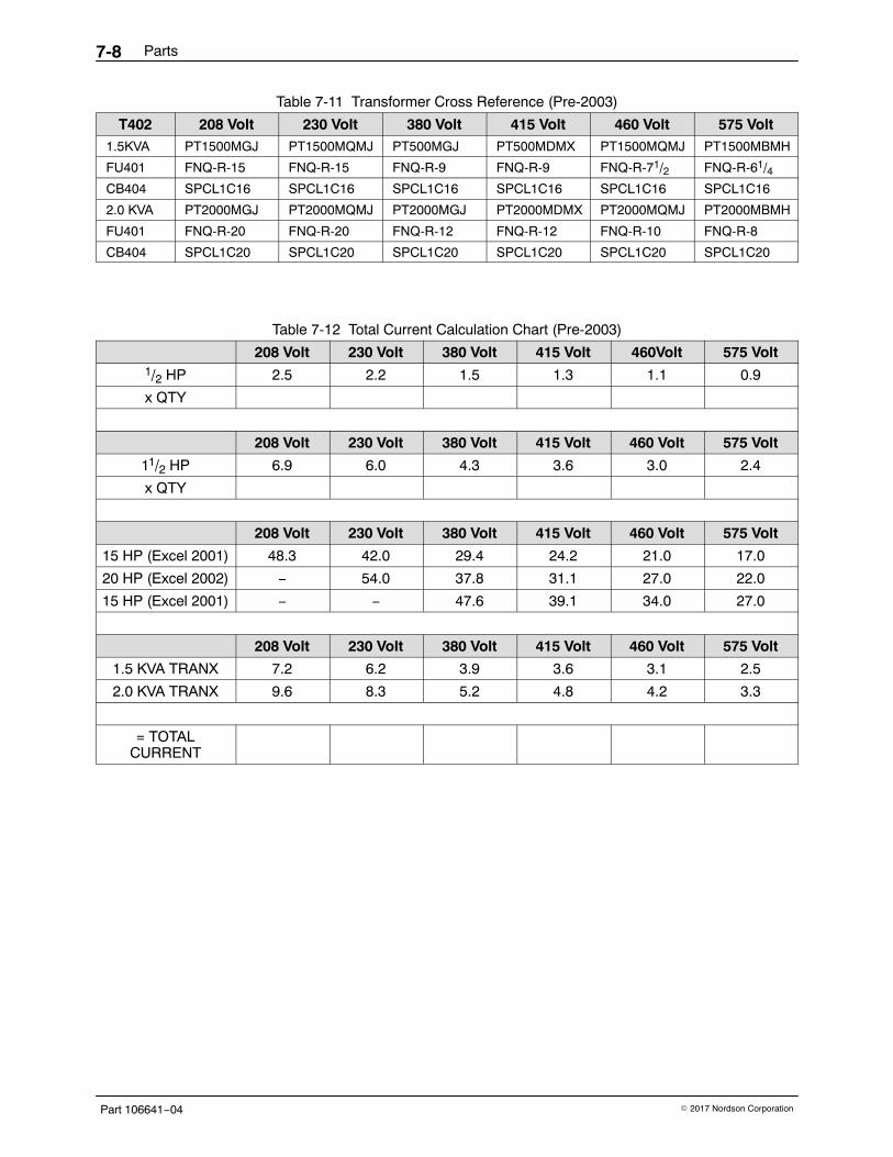
Parts7-8
Part 106641−04 � 2017 Nordson Corporation
Table 7-11 Transformer Cross Reference (Pre-2003)
T402 208 Volt 230 Volt 380 Volt 415 Volt 460 Volt 575 Volt1.5KVA PT1500MGJ PT1500MQMJ PT500MGJ PT500MDMX PT1500MQMJ PT1500MBMH
FU401 FNQ-R-15 FNQ-R-15 FNQ-R-9 FNQ-R-9 FNQ-R-71/2 FNQ-R-61/4CB404 SPCL1C16 SPCL1C16 SPCL1C16 SPCL1C16 SPCL1C16 SPCL1C16
2.0 KVA PT2000MGJ PT2000MQMJ PT2000MGJ PT2000MDMX PT2000MQMJ PT2000MBMH
FU401 FNQ-R-20 FNQ-R-20 FNQ-R-12 FNQ-R-12 FNQ-R-10 FNQ-R-8
CB404 SPCL1C20 SPCL1C20 SPCL1C20 SPCL1C20 SPCL1C20 SPCL1C20
Table 7-12 Total Current Calculation Chart (Pre-2003)
208 Volt 230 Volt 380 Volt 415 Volt 460Volt 575 Volt1/2 HP 2.5 2.2 1.5 1.3 1.1 0.9
x QTY
208 Volt 230 Volt 380 Volt 415 Volt 460 Volt 575 Volt
11/2 HP 6.9 6.0 4.3 3.6 3.0 2.4
x QTY
208 Volt 230 Volt 380 Volt 415 Volt 460 Volt 575 Volt
15 HP (Excel 2001) 48.3 42.0 29.4 24.2 21.0 17.0
20 HP (Excel 2002) − 54.0 37.8 31.1 27.0 22.0
15 HP (Excel 2001) − − 47.6 39.1 34.0 27.0
208 Volt 230 Volt 380 Volt 415 Volt 460 Volt 575 Volt
1.5 KVA TRANX 7.2 6.2 3.9 3.6 3.1 2.5
2.0 KVA TRANX 9.6 8.3 5.2 4.8 4.2 3.3
= TOTALCURRENT
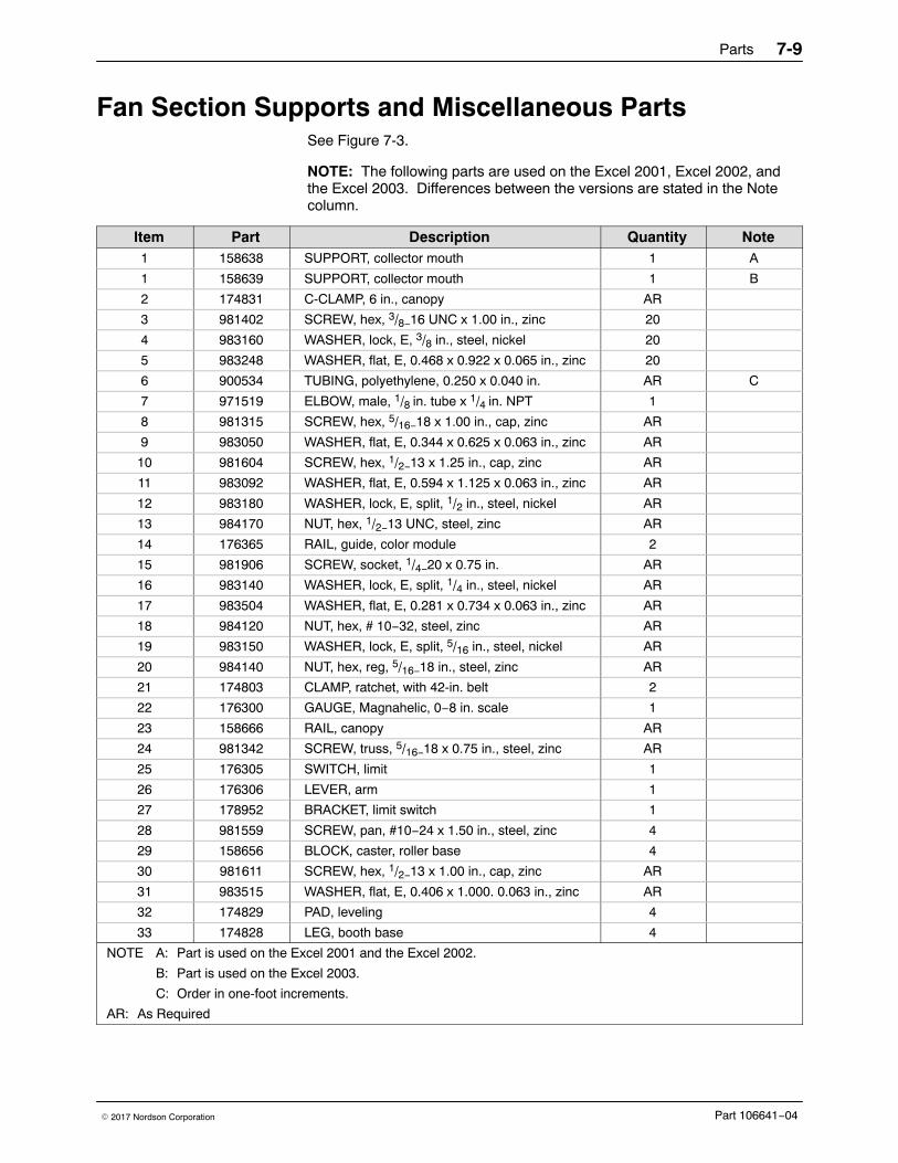
Parts 7-9
Part 106641−04� 2017 Nordson Corporation
Fan Section Supports and Miscellaneous Parts See Figure 7-3.
NOTE: The following parts are used on the Excel 2001, Excel 2002, andthe Excel 2003. Differences between the versions are stated in the Notecolumn.
Item Part Description Quantity Note1 158638 SUPPORT, collector mouth 1 A
1 158639 SUPPORT, collector mouth 1 B
2 174831 C-CLAMP, 6 in., canopy AR
3 981402 SCREW, hex, 3/8−16 UNC x 1.00 in., zinc 20
4 983160 WASHER, lock, E, 3/8 in., steel, nickel 20
5 983248 WASHER, flat, E, 0.468 x 0.922 x 0.065 in., zinc 20
6 900534 TUBING, polyethylene, 0.250 x 0.040 in. AR C
7 971519 ELBOW, male, 1/8 in. tube x 1/4 in. NPT 1
8 981315 SCREW, hex, 5/16−18 x 1.00 in., cap, zinc AR
9 983050 WASHER, flat, E, 0.344 x 0.625 x 0.063 in., zinc AR
10 981604 SCREW, hex, 1/2−13 x 1.25 in., cap, zinc AR
11 983092 WASHER, flat, E, 0.594 x 1.125 x 0.063 in., zinc AR
12 983180 WASHER, lock, E, split, 1/2 in., steel, nickel AR
13 984170 NUT, hex, 1/2−13 UNC, steel, zinc AR
14 176365 RAIL, guide, color module 2
15 981906 SCREW, socket, 1/4−20 x 0.75 in. AR
16 983140 WASHER, lock, E, split, 1/4 in., steel, nickel AR
17 983504 WASHER, flat, E, 0.281 x 0.734 x 0.063 in., zinc AR
18 984120 NUT, hex, # 10−32, steel, zinc AR
19 983150 WASHER, lock, E, split, 5/16 in., steel, nickel AR
20 984140 NUT, hex, reg, 5/16−18 in., steel, zinc AR
21 174803 CLAMP, ratchet, with 42-in. belt 2
22 176300 GAUGE, Magnahelic, 0−8 in. scale 1
23 158666 RAIL, canopy AR
24 981342 SCREW, truss, 5/16−18 x 0.75 in., steel, zinc AR
25 176305 SWITCH, limit 1
26 176306 LEVER, arm 1
27 178952 BRACKET, limit switch 1
28 981559 SCREW, pan, #10−24 x 1.50 in., steel, zinc 4
29 158656 BLOCK, caster, roller base 4
30 981611 SCREW, hex, 1/2−13 x 1.00 in., cap, zinc AR
31 983515 WASHER, flat, E, 0.406 x 1.000. 0.063 in., zinc AR
32 174829 PAD, leveling 4
33 174828 LEG, booth base 4
NOTE A: Part is used on the Excel 2001 and the Excel 2002.
B: Part is used on the Excel 2003.
C: Order in one-foot increments.
AR: As Required
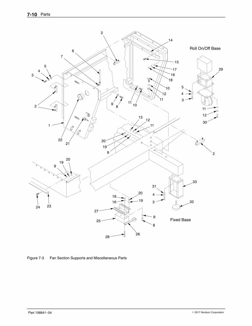
Parts7-10
Part 106641−04 � 2017 Nordson Corporation
Fixed Base
Roll On/Off Base
9
1
2
34
5
7
6
2
98
1110
11
12
10
14
15
1716
18
2
29
11
12
30
3
4
5
33
32
31
4
3
2826
8
9
19
20
27
18
16
25
24 23
1920
2221
9
19
20
1112
13
Figure 7-3 Fan Section Supports and Miscellaneous Parts
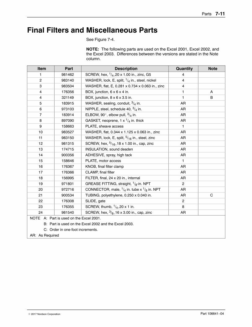
Parts 7-11
Part 106641−04� 2017 Nordson Corporation
Final Filters and Miscellaneous Parts See Figure 7-4.
NOTE: The following parts are used on the Excel 2001, Excel 2002, andthe Excel 2003. Differences between the versions are stated in the Notecolumn.
Item Part Description Quantity Note1 981462 SCREW, hex, 1/4−20 x 1.00 in., zinc, G5 4
2 983140 WASHER, lock, E, split, 1/4 in., steel, nickel 4
3 983504 WASHER, flat, E, 0.281 x 0.734 x 0.063 in., zinc 4
4 176356 BOX, junction, 6 x 6 x 4 in. 1 A
4 321149 BOX, junction, 8 x 6 x 3.5 in. 1 B
5 183915 WASHER, sealing, conduit, 3/4 in. AR
6 973103 NIPPLE, steel, schedule 40, 3/4 in. AR
7 183914 ELBOW, 90�, elbow pull, 3/4 in. AR
8 897090 GASKET, neoprene, 1 x 1/4 in. thick AR
9 158663 PLATE, sheave access 1
10 983527 WASHER, flat, 0.344 x 1.125 x 0.063 in., zinc AR
11 983150 WASHER, lock, E, split, 5/16 in., steel, zinc AR
12 981315 SCREW, hex, 5/16−18 x 1.00 in., cap, zinc AR
13 174715 INSULATION, sound deaden AR
14 900356 ADHESIVE, spray, high tack AR
15 158646 PLATE, motor access 1
16 176367 KNOB, final filter clamp AR
17 176366 CLAMP, final filter AR
18 156995 FILTER, final, 24 x 20 in., internal AR
19 971801 GREASE FITTING, straight, 1/8-in. NPT 2
20 972716 CONNECTOR, male, 1/4 in. tube x 1/8 in. NPT AR
21 900534 TUBING, polyethylene, 0.250 x 0.040 in. AR C
22 176308 SLIDE, gate 2
23 176355 SCREW, thumb, 1/4−20 x 1 in. 8
24 981540 SCREW, hex, 3/8−16 x 3.00 in., cap, zinc AR
NOTE A: Part is used on the Excel 2001.
B: Part is used on the Excel 2002 and the Excel 2003.
C: Order in one-foot increments.
AR: As Required
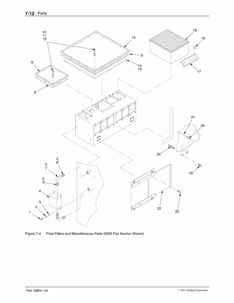
Parts7-12
Part 106641−04 � 2017 Nordson Corporation
8
9
12 15
8
13
18
16
17
6
7
6
4
32
1 2322
19
24
21
20
1011
14
5
5
5
Figure 7-4 Final Filters and Miscellaneous Parts (2003 Fan Section Shown)
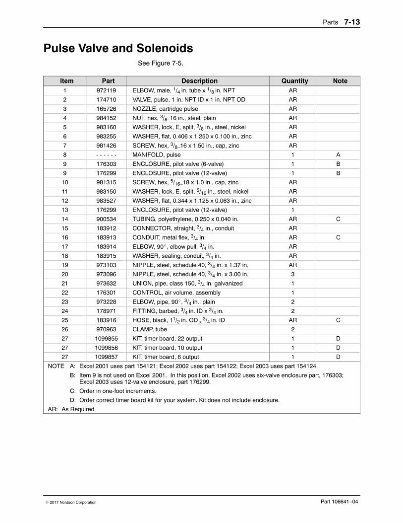
Parts 7-13
Part 106641−04� 2017 Nordson Corporation
Pulse Valve and Solenoids See Figure 7-5.
Item Part Description Quantity Note1 972119 ELBOW, male, 1/4 in. tube x 1/8 in. NPT AR
2 174710 VALVE, pulse, 1 in. NPT ID x 1 in. NPT OD AR
3 165726 NOZZLE, cartridge pulse AR
4 984152 NUT, hex, 3/8−16 in., steel, plain AR
5 983160 WASHER, lock, E, split, 3/8 in., steel, nickel AR
6 983255 WASHER, flat, 0.406 x 1.250 x 0.100 in., zinc AR
7 981426 SCREW, hex, 3/8−16 x 1.50 in., cap, zinc AR
8 - - - - - - MANIFOLD, pulse 1 A
9 176303 ENCLOSURE, pilot valve (6-valve) 1 B
9 176299 ENCLOSURE, pilot valve (12-valve) 1 B
10 981315 SCREW, hex, 5/16−18 x 1.0 in., cap, zinc AR
11 983150 WASHER, lock, E, split, 5/16 in., steel, nickel AR
12 983527 WASHER, flat, 0.344 x 1.125 x 0.063 in., zinc AR
13 176299 ENCLOSURE, pilot valve (12-valve) 1
14 900534 TUBING, polyethylene, 0.250 x 0.040 in. AR C
15 183912 CONNECTOR, straight, 3/4 in., conduit AR
16 183913 CONDUIT, metal flex, 3/4 in. AR C
17 183914 ELBOW, 90�, elbow pull, 3/4 in. AR
18 183915 WASHER, sealing, conduit, 3/4 in. AR
19 973103 NIPPLE, steel, schedule 40, 3/4 in. x 1.37 in. AR
20 973096 NIPPLE, steel, schedule 40, 3/4 in. x 3.00 in. 3
21 973632 UNION, pipe, class 150, 3/4 in. galvanized 1
22 176301 CONTROL, air volume, assembly 1
23 973228 ELBOW, pipe, 90�, 3/4 in., plain 2
24 178971 FITTING, barbed, 3/4 in. ID x 3/4 in. 2
25 183916 HOSE, black, 11/2 in. OD x 3/4 in. ID AR C
26 970963 CLAMP, tube 2
27 1099855 KIT, timer board, 22 output 1 D
27 1099856 KIT, timer board, 10 output 1 D
27 1099857 KIT, timer board, 6 output 1 D
NOTE A: Excel 2001 uses part 154121; Excel 2002 uses part 154122; Excel 2003 uses part 154124.
B: Item 9 is not used on Excel 2001. In this position, Excel 2002 uses six-valve enclosure part, 176303;Excel 2003 uses 12-valve enclosure, part 176299.
C: Order in one-foot increments.
D: Order correct timer board kit for your system. Kit does not include enclosure.
AR: As Required
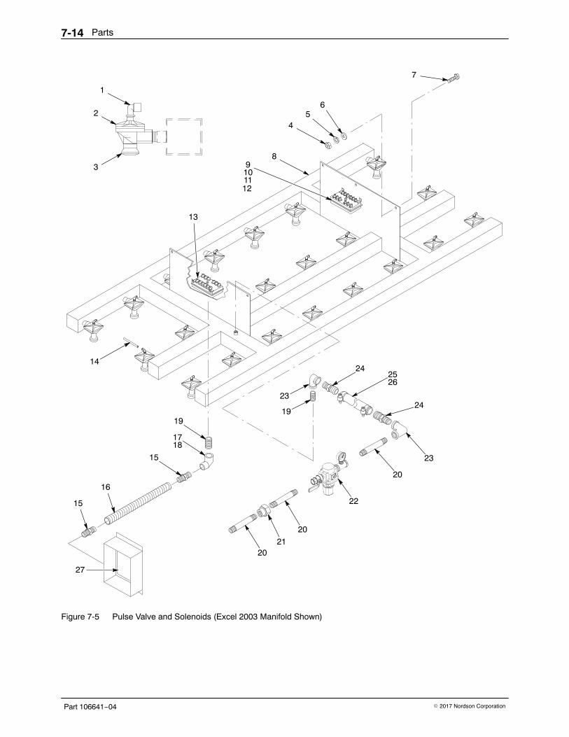
Parts7-14
Part 106641−04 � 2017 Nordson Corporation
20
1
2
3
45
6
7
89101112
13
14
15
15
16
1718
19
21
20
22
20
23
24
2526
24
23
19
27
Figure 7-5 Pulse Valve and Solenoids (Excel 2003 Manifold Shown)
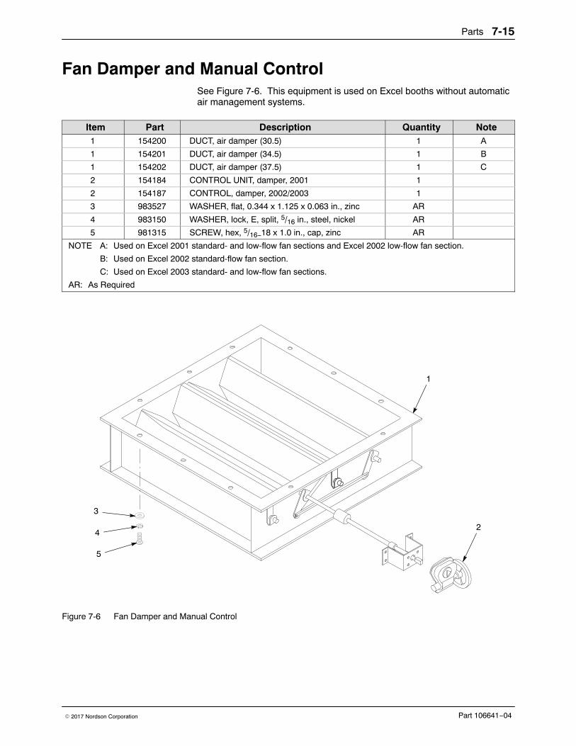
Parts 7-15
Part 106641−04� 2017 Nordson Corporation
Fan Damper and Manual ControlSee Figure 7-6. This equipment is used on Excel booths without automaticair management systems.
Item Part Description Quantity Note1 154200 DUCT, air damper (30.5) 1 A
1 154201 DUCT, air damper (34.5) 1 B
1 154202 DUCT, air damper (37.5) 1 C
2 154184 CONTROL UNIT, damper, 2001 1
2 154187 CONTROL, damper, 2002/2003 1
3 983527 WASHER, flat, 0.344 x 1.125 x 0.063 in., zinc AR
4 983150 WASHER, lock, E, split, 5/16 in., steel, nickel AR
5 981315 SCREW, hex, 5/16−18 x 1.0 in., cap, zinc AR
NOTE A: Used on Excel 2001 standard- and low-flow fan sections and Excel 2002 low-flow fan section.
B: Used on Excel 2002 standard-flow fan section.
C: Used on Excel 2003 standard- and low-flow fan sections.
AR: As Required
1
2
5
4
3
Figure 7-6 Fan Damper and Manual Control
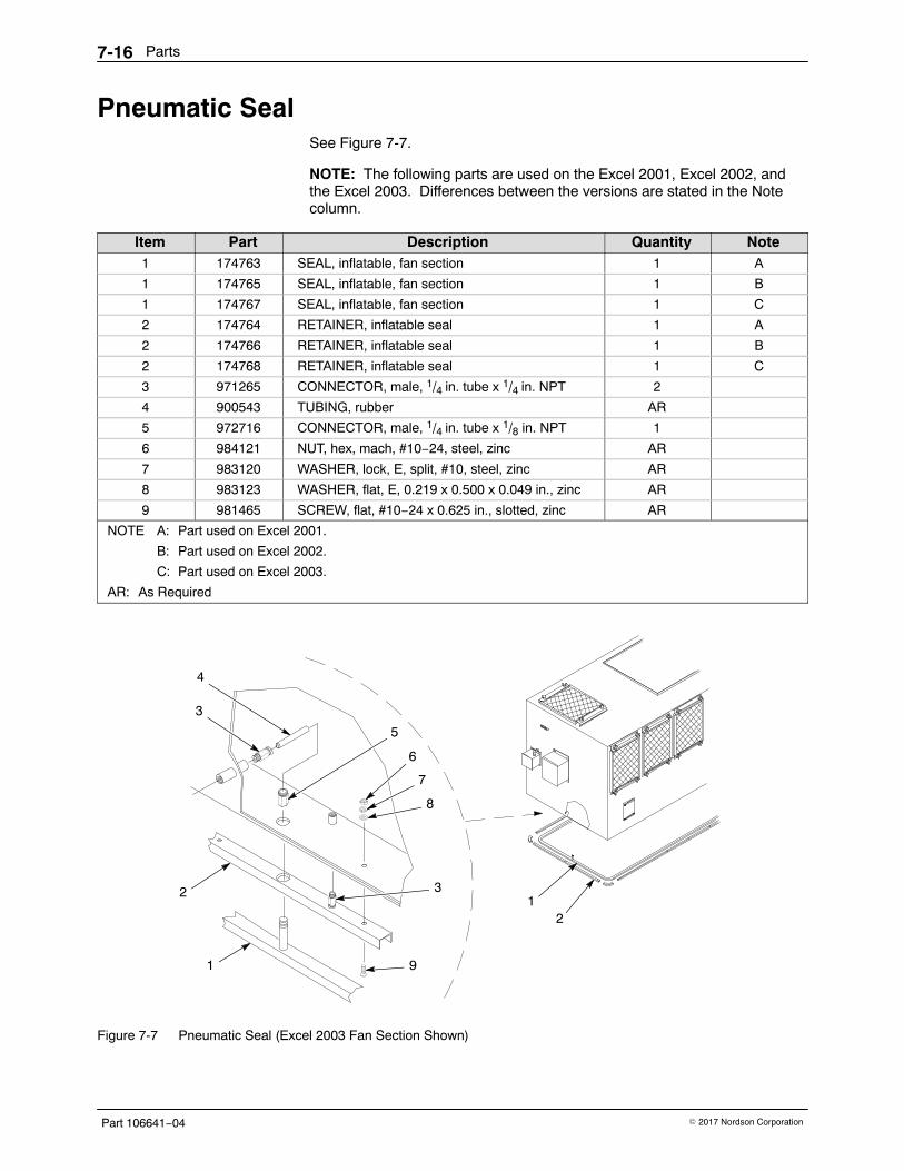
Parts7-16
Part 106641−04 � 2017 Nordson Corporation
Pneumatic SealSee Figure 7-7.
NOTE: The following parts are used on the Excel 2001, Excel 2002, andthe Excel 2003. Differences between the versions are stated in the Notecolumn.
Item Part Description Quantity Note1 174763 SEAL, inflatable, fan section 1 A
1 174765 SEAL, inflatable, fan section 1 B
1 174767 SEAL, inflatable, fan section 1 C
2 174764 RETAINER, inflatable seal 1 A
2 174766 RETAINER, inflatable seal 1 B
2 174768 RETAINER, inflatable seal 1 C
3 971265 CONNECTOR, male, 1/4 in. tube x 1/4 in. NPT 2
4 900543 TUBING, rubber AR
5 972716 CONNECTOR, male, 1/4 in. tube x 1/8 in. NPT 1
6 984121 NUT, hex, mach, #10−24, steel, zinc AR
7 983120 WASHER, lock, E, split, #10, steel, zinc AR
8 983123 WASHER, flat, E, 0.219 x 0.500 x 0.049 in., zinc AR
9 981465 SCREW, flat, #10−24 x 0.625 in., slotted, zinc AR
NOTE A: Part used on Excel 2001.
B: Part used on Excel 2002.
C: Part used on Excel 2003.
AR: As Required
21
4
3
5
6
7
8
9
32
1
Figure 7-7 Pneumatic Seal (Excel 2003 Fan Section Shown)
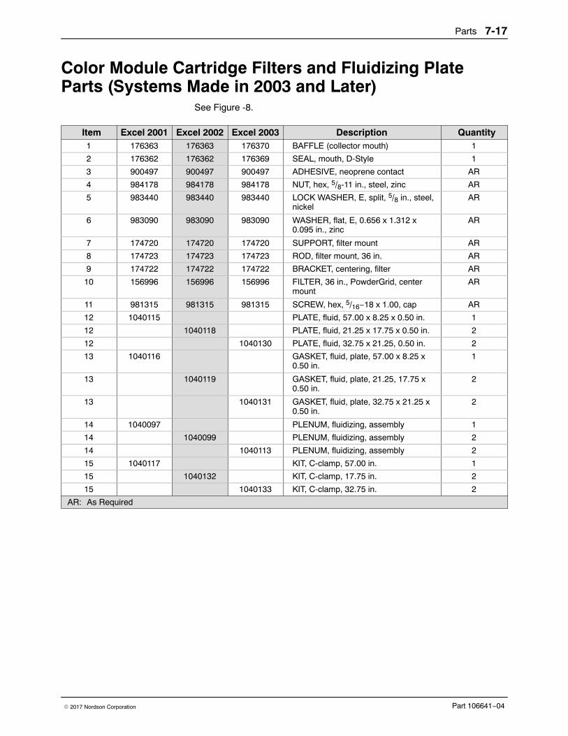
Parts 7-17
Part 106641−04� 2017 Nordson Corporation
Color Module Cartridge Filters and Fluidizing PlateParts (Systems Made in 2003 and Later)
See Figure -8.
Item Excel 2001 Excel 2002 Excel 2003 Description Quantity1 176363 176363 176370 BAFFLE (collector mouth) 1
2 176362 176362 176369 SEAL, mouth, D-Style 1
3 900497 900497 900497 ADHESIVE, neoprene contact AR
4 984178 984178 984178 NUT, hex, 5/8-11 in., steel, zinc AR
5 983440 983440 983440 LOCK WASHER, E, split, 5/8 in., steel,nickel
AR
6 983090 983090 983090 WASHER, flat, E, 0.656 x 1.312 x0.095 in., zinc
AR
7 174720 174720 174720 SUPPORT, filter mount AR
8 174723 174723 174723 ROD, filter mount, 36 in. AR
9 174722 174722 174722 BRACKET, centering, filter AR
10 156996 156996 156996 FILTER, 36 in., PowderGrid, centermount
AR
11 981315 981315 981315 SCREW, hex, 5/16−18 x 1.00, cap AR
12 1040115 PLATE, fluid, 57.00 x 8.25 x 0.50 in. 1
12 1040118 PLATE, fluid, 21.25 x 17.75 x 0.50 in. 2
12 1040130 PLATE, fluid, 32.75 x 21.25, 0.50 in. 2
13 1040116 GASKET, fluid, plate, 57.00 x 8.25 x0.50 in.
1
13 1040119 GASKET, fluid, plate, 21.25, 17.75 x0.50 in.
2
13 1040131 GASKET, fluid, plate, 32.75 x 21.25 x0.50 in.
2
14 1040097 PLENUM, fluidizing, assembly 1
14 1040099 PLENUM, fluidizing, assembly 2
14 1040113 PLENUM, fluidizing, assembly 2
15 1040117 KIT, C-clamp, 57.00 in. 1
15 1040132 KIT, C-clamp, 17.75 in. 2
15 1040133 KIT, C-clamp, 32.75 in. 2
AR: As Required
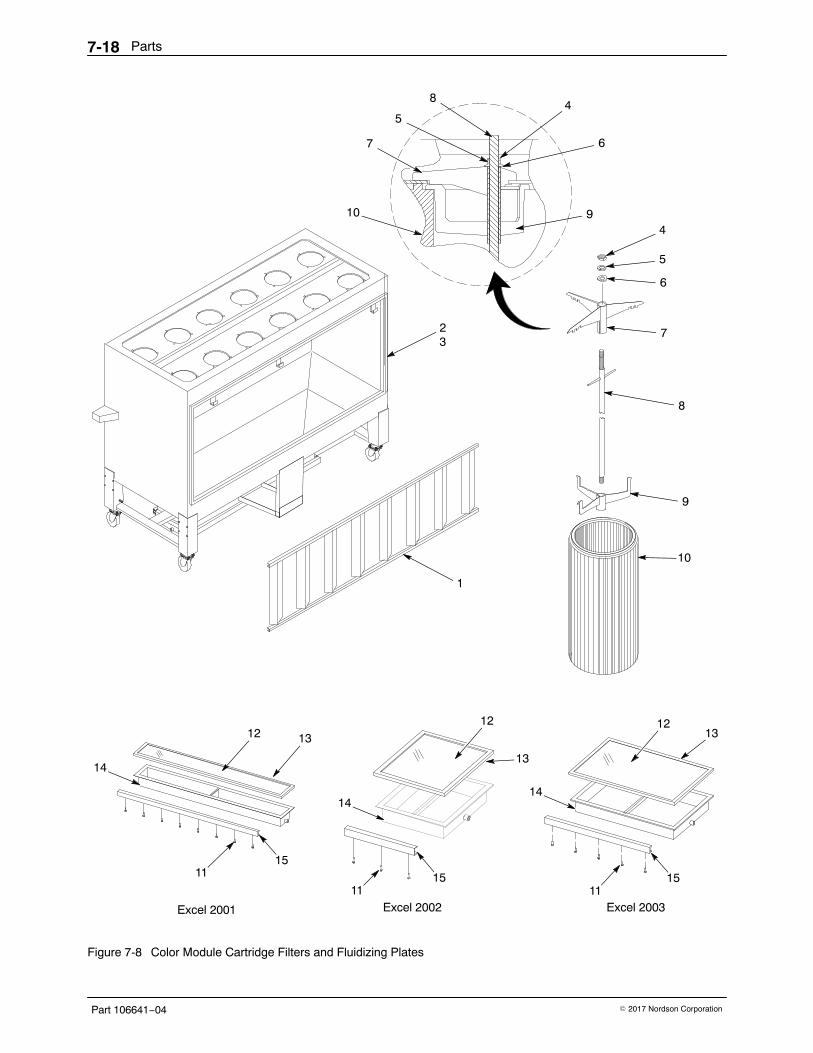
Parts7-18
Part 106641−04 � 2017 Nordson Corporation
2
10 9
6
7
8
9
10
1
8
7
3
5
4
1115
1312
14
1115
13
12
14
1115
1312
14
Excel 2001 Excel 2002 Excel 2003
45
6
Figure 7-8 Color Module Cartridge Filters and Fluidizing Plates
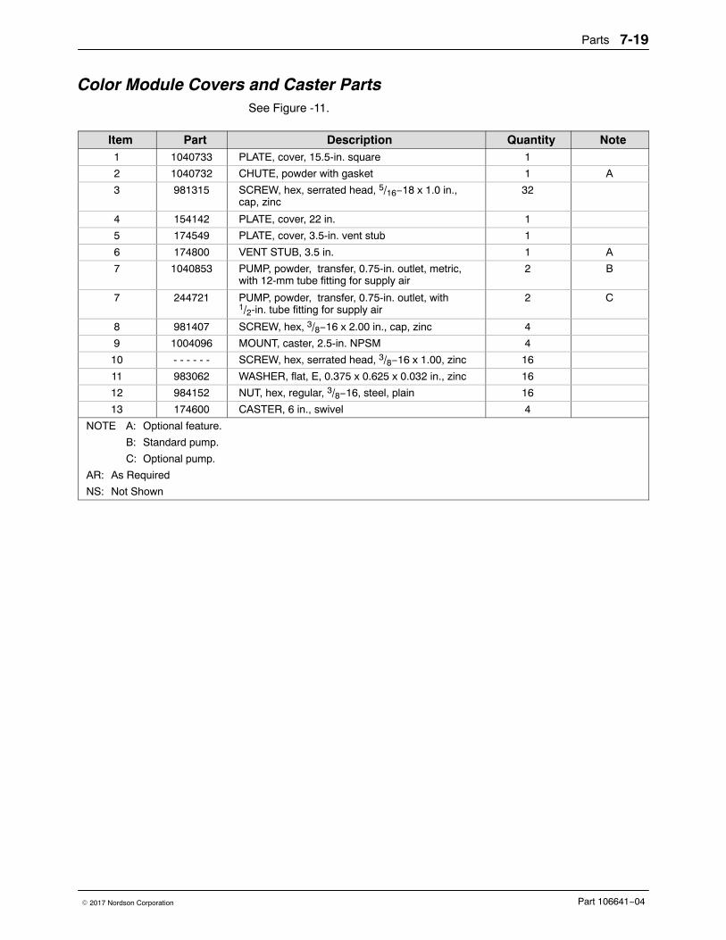
Parts 7-19
Part 106641−04� 2017 Nordson Corporation
Color Module Covers and Caster PartsSee Figure -11.
Item Part Description Quantity Note1 1040733 PLATE, cover, 15.5-in. square 1
2 1040732 CHUTE, powder with gasket 1 A
3 981315 SCREW, hex, serrated head, 5/16−18 x 1.0 in.,cap, zinc
32
4 154142 PLATE, cover, 22 in. 1
5 174549 PLATE, cover, 3.5-in. vent stub 1
6 174800 VENT STUB, 3.5 in. 1 A
7 1040853 PUMP, powder, transfer, 0.75-in. outlet, metric,with 12-mm tube fitting for supply air
2 B
7 244721 PUMP, powder, transfer, 0.75-in. outlet, with1/2-in. tube fitting for supply air
2 C
8 981407 SCREW, hex, 3/8−16 x 2.00 in., cap, zinc 4
9 1004096 MOUNT, caster, 2.5-in. NPSM 4
10 - - - - - - SCREW, hex, serrated head, 3/8−16 x 1.00, zinc 16
11 983062 WASHER, flat, E, 0.375 x 0.625 x 0.032 in., zinc 16
12 984152 NUT, hex, regular, 3/8−16, steel, plain 16
13 174600 CASTER, 6 in., swivel 4
NOTE A: Optional feature.
B: Standard pump.
C: Optional pump.
AR: As Required
NS: Not Shown
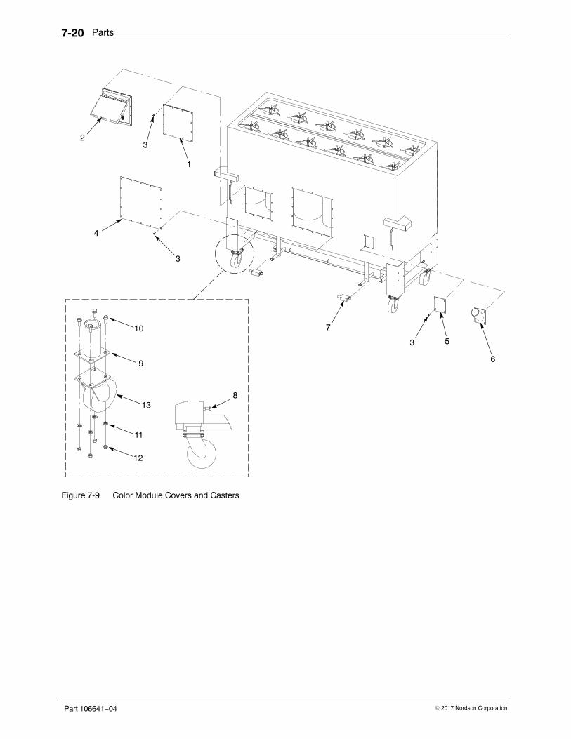
Parts7-20
Part 106641−04 � 2017 Nordson Corporation
4
2
1
3
3
7
6
5
12
11
13
9
10
8
3
Figure 7-9 Color Module Covers and Casters
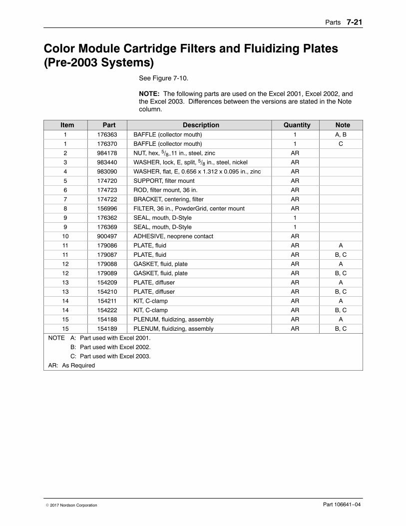
Parts 7-21
Part 106641−04� 2017 Nordson Corporation
Color Module Cartridge Filters and Fluidizing Plates(Pre-2003 Systems)
See Figure 7-10.
NOTE: The following parts are used on the Excel 2001, Excel 2002, andthe Excel 2003. Differences between the versions are stated in the Notecolumn.
Item Part Description Quantity Note1 176363 BAFFLE (collector mouth) 1 A, B
1 176370 BAFFLE (collector mouth) 1 C
2 984178 NUT, hex, 5/8−11 in., steel, zinc AR
3 983440 WASHER, lock, E, split, 5/8 in., steel, nickel AR
4 983090 WASHER, flat, E, 0.656 x 1.312 x 0.095 in., zinc AR
5 174720 SUPPORT, filter mount AR
6 174723 ROD, filter mount, 36 in. AR
7 174722 BRACKET, centering, filter AR
8 156996 FILTER, 36 in., PowderGrid, center mount AR
9 176362 SEAL, mouth, D-Style 1
9 176369 SEAL, mouth, D-Style 1
10 900497 ADHESIVE, neoprene contact AR
11 179086 PLATE, fluid AR A
11 179087 PLATE, fluid AR B, C
12 179088 GASKET, fluid, plate AR A
12 179089 GASKET, fluid, plate AR B, C
13 154209 PLATE, diffuser AR A
13 154210 PLATE, diffuser AR B, C
14 154211 KIT, C-clamp AR A
14 154222 KIT, C-clamp AR B, C
15 154188 PLENUM, fluidizing, assembly AR A
15 154189 PLENUM, fluidizing, assembly AR B, C
NOTE A: Part used with Excel 2001.
B: Part used with Excel 2002.
C: Part used with Excel 2003.
AR: As Required
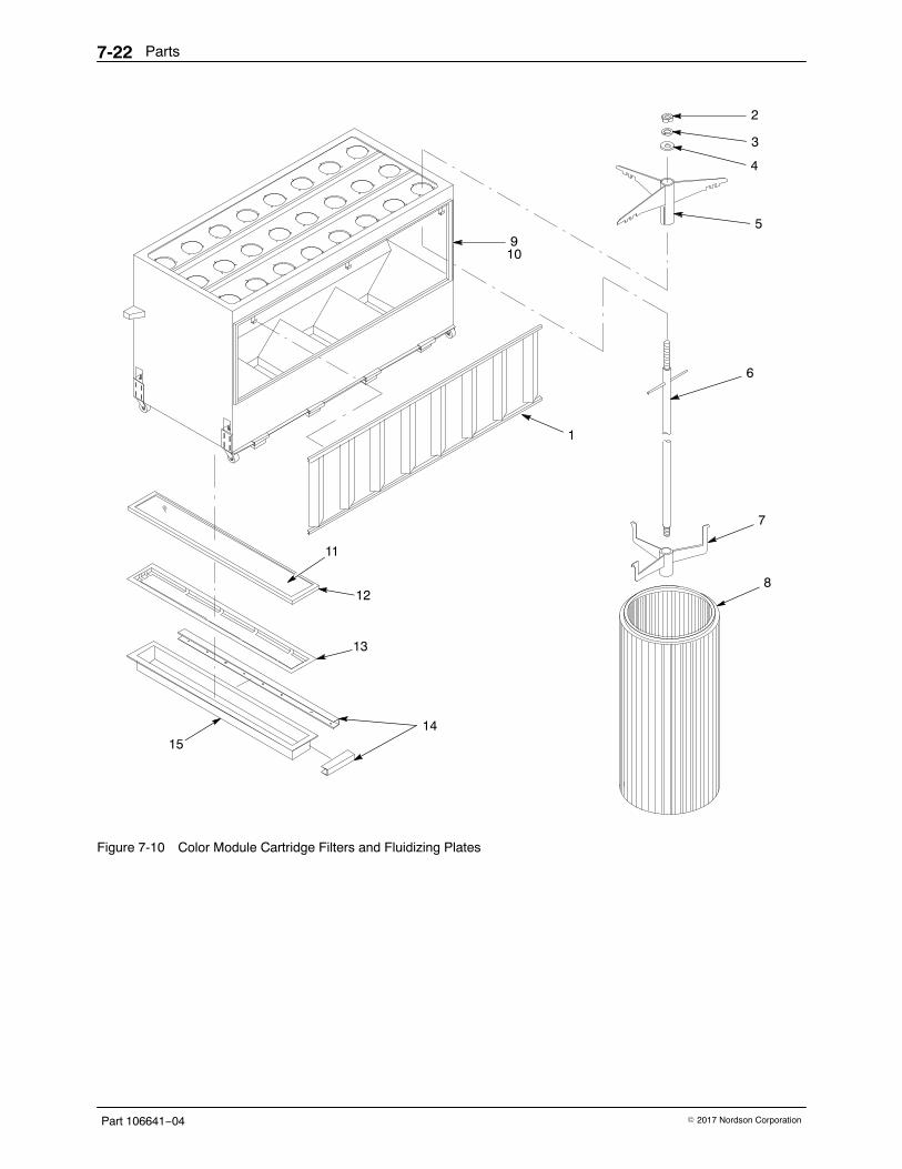
Parts7-22
Part 106641−04 � 2017 Nordson Corporation
2
9
3
4
5
6
7
8
1
10
11
12
13
1514
Figure 7-10 Color Module Cartridge Filters and Fluidizing Plates
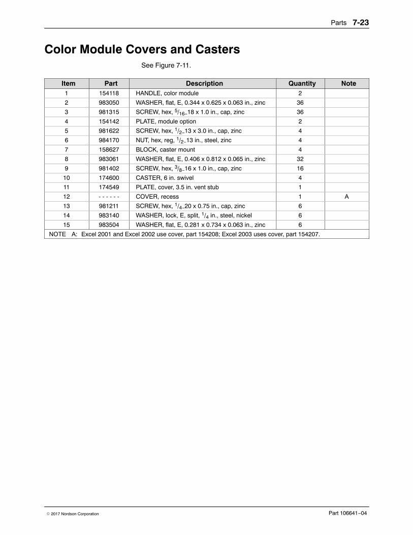
Parts 7-23
Part 106641−04� 2017 Nordson Corporation
Color Module Covers and CastersSee Figure 7-11.
Item Part Description Quantity Note1 154118 HANDLE, color module 2
2 983050 WASHER, flat, E, 0.344 x 0.625 x 0.063 in., zinc 36
3 981315 SCREW, hex, 5/16−18 x 1.0 in., cap, zinc 36
4 154142 PLATE, module option 2
5 981622 SCREW, hex, 1/2−13 x 3.0 in., cap, zinc 4
6 984170 NUT, hex, reg, 1/2−13 in., steel, zinc 4
7 158627 BLOCK, caster mount 4
8 983061 WASHER, flat, E, 0.406 x 0.812 x 0.065 in., zinc 32
9 981402 SCREW, hex, 3/8−16 x 1.0 in., cap, zinc 16
10 174600 CASTER, 6 in. swivel 4
11 174549 PLATE, cover, 3.5 in. vent stub 1
12 - - - - - - COVER, recess 1 A
13 981211 SCREW, hex, 1/4−20 x 0.75 in., cap, zinc 6
14 983140 WASHER, lock, E, split, 1/4 in., steel, nickel 6
15 983504 WASHER, flat, E, 0.281 x 0.734 x 0.063 in., zinc 6
NOTE A: Excel 2001 and Excel 2002 use cover, part 154208; Excel 2003 uses cover, part 154207.
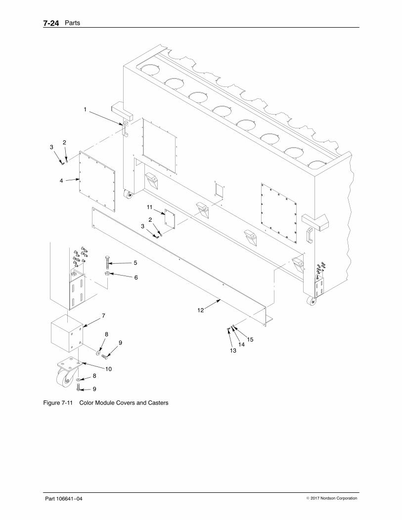
Parts7-24
Part 106641−04 � 2017 Nordson Corporation
12
1
23
4
5
6
7
89
108
9
11
23
1314
15
Figure 7-11 Color Module Covers and Casters
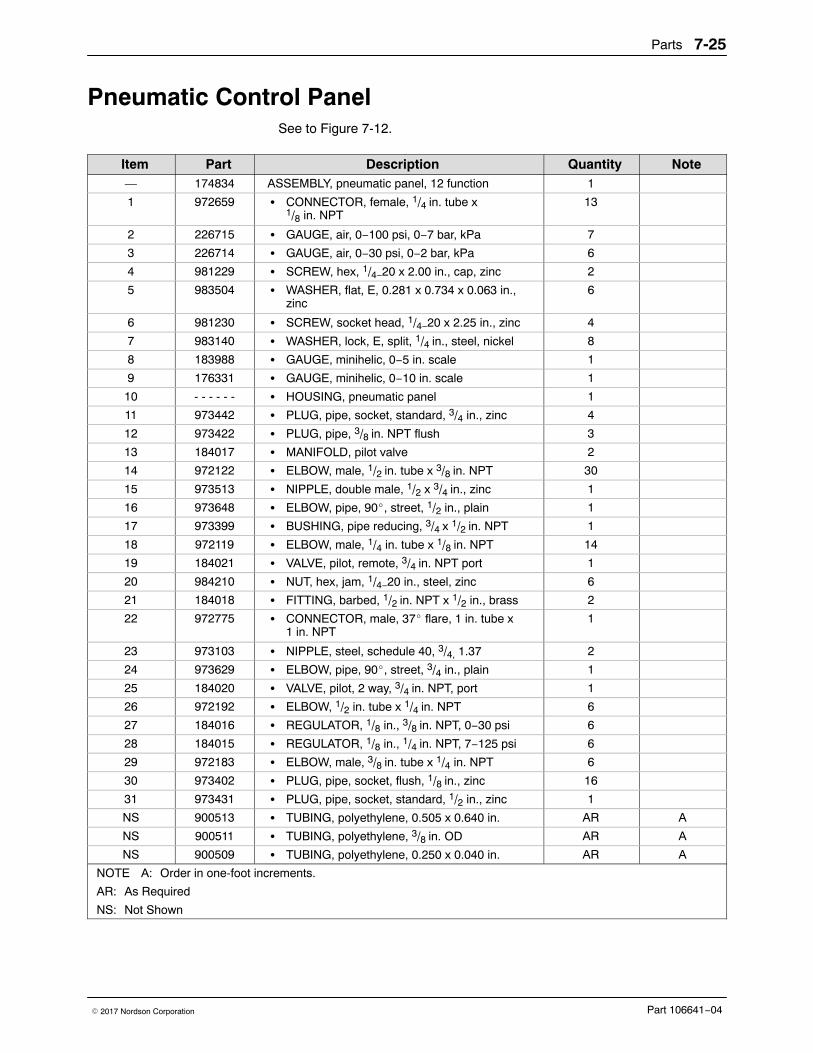
Parts 7-25
Part 106641−04� 2017 Nordson Corporation
Pneumatic Control PanelSee to Figure 7-12.
Item Part Description Quantity Note— 174834 ASSEMBLY, pneumatic panel, 12 function 1
1 972659 � CONNECTOR, female, 1/4 in. tube x1/8 in. NPT
13
2 226715 � GAUGE, air, 0−100 psi, 0−7 bar, kPa 7
3 226714 � GAUGE, air, 0−30 psi, 0−2 bar, kPa 6
4 981229 � SCREW, hex, 1/4−20 x 2.00 in., cap, zinc 2
5 983504 � WASHER, flat, E, 0.281 x 0.734 x 0.063 in.,zinc
6
6 981230 � SCREW, socket head, 1/4−20 x 2.25 in., zinc 4
7 983140 � WASHER, lock, E, split, 1/4 in., steel, nickel 8
8 183988 � GAUGE, minihelic, 0−5 in. scale 1
9 176331 � GAUGE, minihelic, 0−10 in. scale 1
10 - - - - - - � HOUSING, pneumatic panel 1
11 973442 � PLUG, pipe, socket, standard, 3/4 in., zinc 4
12 973422 � PLUG, pipe, 3/8 in. NPT flush 3
13 184017 � MANIFOLD, pilot valve 2
14 972122 � ELBOW, male, 1/2 in. tube x 3/8 in. NPT 30
15 973513 � NIPPLE, double male, 1/2 x 3/4 in., zinc 1
16 973648 � ELBOW, pipe, 90�, street, 1/2 in., plain 1
17 973399 � BUSHING, pipe reducing, 3/4 x 1/2 in. NPT 1
18 972119 � ELBOW, male, 1/4 in. tube x 1/8 in. NPT 14
19 184021 � VALVE, pilot, remote, 3/4 in. NPT port 1
20 984210 � NUT, hex, jam, 1/4−20 in., steel, zinc 6
21 184018 � FITTING, barbed, 1/2 in. NPT x 1/2 in., brass 2
22 972775 � CONNECTOR, male, 37� flare, 1 in. tube x1 in. NPT
1
23 973103 � NIPPLE, steel, schedule 40, 3/4, 1.37 2
24 973629 � ELBOW, pipe, 90�, street, 3/4 in., plain 1
25 184020 � VALVE, pilot, 2 way, 3/4 in. NPT, port 1
26 972192 � ELBOW, 1/2 in. tube x 1/4 in. NPT 6
27 184016 � REGULATOR, 1/8 in., 3/8 in. NPT, 0−30 psi 6
28 184015 � REGULATOR, 1/8 in., 1/4 in. NPT, 7−125 psi 6
29 972183 � ELBOW, male, 3/8 in. tube x 1/4 in. NPT 6
30 973402 � PLUG, pipe, socket, flush, 1/8 in., zinc 16
31 973431 � PLUG, pipe, socket, standard, 1/2 in., zinc 1
NS 900513 � TUBING, polyethylene, 0.505 x 0.640 in. AR A
NS 900511 � TUBING, polyethylene, 3/8 in. OD AR A
NS 900509 � TUBING, polyethylene, 0.250 x 0.040 in. AR A
NOTE A: Order in one-foot increments.
AR: As Required
NS: Not Shown
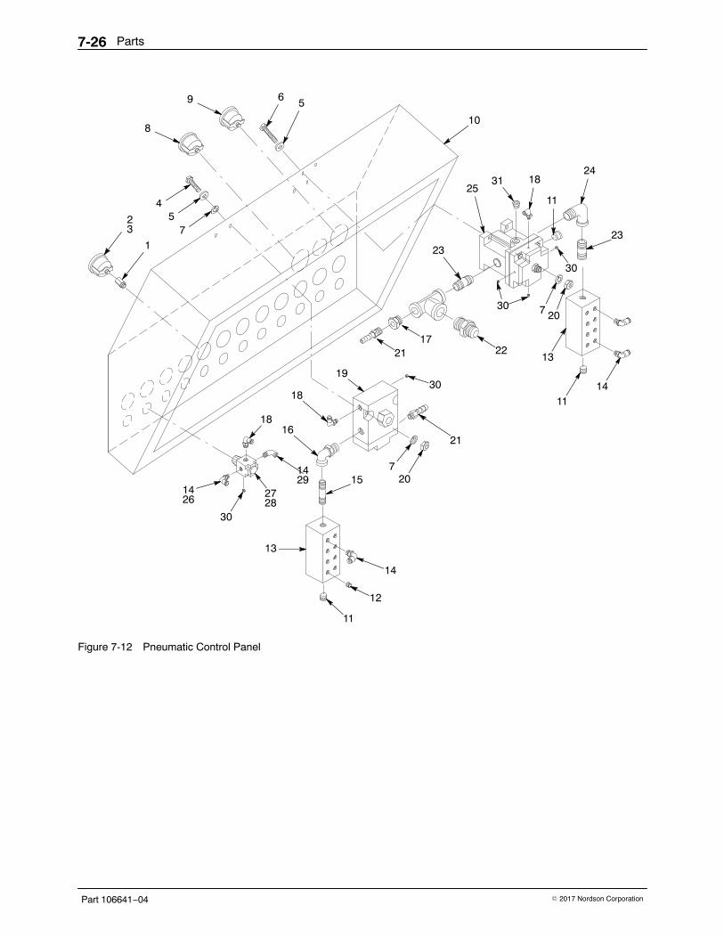
Parts7-26
Part 106641−04 � 2017 Nordson Corporation
1
2 54
56
10
24
11
18
19
18
23
14
13
12
18
14 27
3
1429
2826
11
21
7 20
13
1114
72015
16
7
8
9
30
30
30
31
23
22
30
2117
25
Figure 7-12 Pneumatic Control Panel
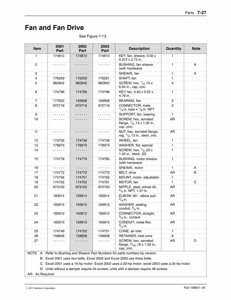
Parts 7-27
Part 106641−04� 2017 Nordson Corporation
Fan and Fan Drive See Figure 7-13.
Item 2001Part
2002Part
2003Part Description Quantity Note
1 174810 174810 174810 KEY, fan, sheave, 0.50 x0.312 x 2.72 in.
1
2 - - - - - - - - - - - - - - - - - - BUSHING, fan sheave(with hardware)
1 A
3 - - - - - - - - - - - - - - - - - - SHEAVE, fan 1 A4 176259 176259 176261 SHAFT, fan 15 982842 982842 982842 SCREW, hex, 1/2−13 x
6.50 in., cap, zinc4
6 174796 174796 174796 KEY, fan, 0.50 x 0.50 x4.79 in.
1
7 177622 183906 183906 BEARING, fan 28 972716 972716 972716 CONNECTOR, male,
1/4 in. tube x 1/8 in. NPT2
9 - - - - - - - - - - - - - - - - - - SUPPORT, fan, bearing 110 - - - - - - - - - - - - - - - - - - SCREW, hex, serrated
flange, 1/2−13 x 1.00 in.,cap, zinc
AR
11 - - - - - - - - - - - - - - - - - - NUT, hex, serrated flange,reg, 1/2−13 in., steel, zinc
AR
12 174735 174736 174736 WHEEL, fan 113 178973 178973 178973 WASHER, flat, special 114 - - - - - - - - - - - - - - - - - - SCREW, hex, 1/2−20 x
1.00 in., black, G51
15 174778 174779 174785 BUSHING, motor sheave(with hardware)
1
16 - - - - - - - - - - - - - - - - - - SHEAVE, motor 1 A17 174772 174772 174773 BELT, drive AR B18 174756 174757 174762 MOUNT, motor, adjustable 119 174752 174755 174761 MOTOR, fan 1 C20 973103 973103 973103 NIPPLE, steel, sched 40,
3/4 in. NPT, 1.37 in.AR
21 183914 183914 183914 ELBOW, 90�, elbow pull,3/4 in.
AR
22 183915 183915 183915 WASHER, sealing,conduit, 3/4 in.
AR
23 183912 183912 183912 CONNECTOR, straight,3/4 in., conduit
AR
24 183913 183913 183913 CONDUIT, metal flex,3/4 in.
AR
25 174749 174750 174751 CONE, air inlet 126 158658 158658 158658 RETAINER, inlet cone 827 - - - - - - - - - - - - - - - - - - SCREW, hex, serrated
flange, 5/16−18 x 1.00 in.,cap, zinc
AR D
NOTE A: Refer to Bushing and Sheave Part Numbers for parts numbers by version.
B: Excel 2001 uses two belts, Excel 2002 and Excel 2003 use three belts.
C: Excel 2001 uses a 15-hp motor; Excel 2002 uses a 20-hp motor; excel 2003 uses a 25-hp motor.
D: Units without a damper require 34 screws; units with a damper require 46 screws.
AR: As Required
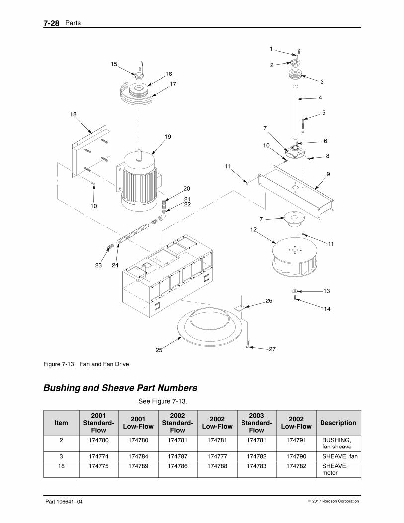
Parts7-28
Part 106641−04 � 2017 Nordson Corporation
18
23
12
19
17
16
20
15 2
1
3
4
5
10
8
7
9
14
13
6
11
7
11
2122
24
25
26
27
10
Figure 7-13 Fan and Fan Drive
Bushing and Sheave Part NumbersSee Figure 7-13.
Item2001
Standard-Flow
2001Low-Flow
2002Standard-
Flow
2002Low-Flow
2003Standard-
Flow
2002Low-Flow Description
2 174780 174780 174781 174781 174781 174791 BUSHING,fan sheave
3 174774 174784 174787 174777 174782 174790 SHEAVE, fan
18 174775 174789 174786 174788 174783 174782 SHEAVE,motor
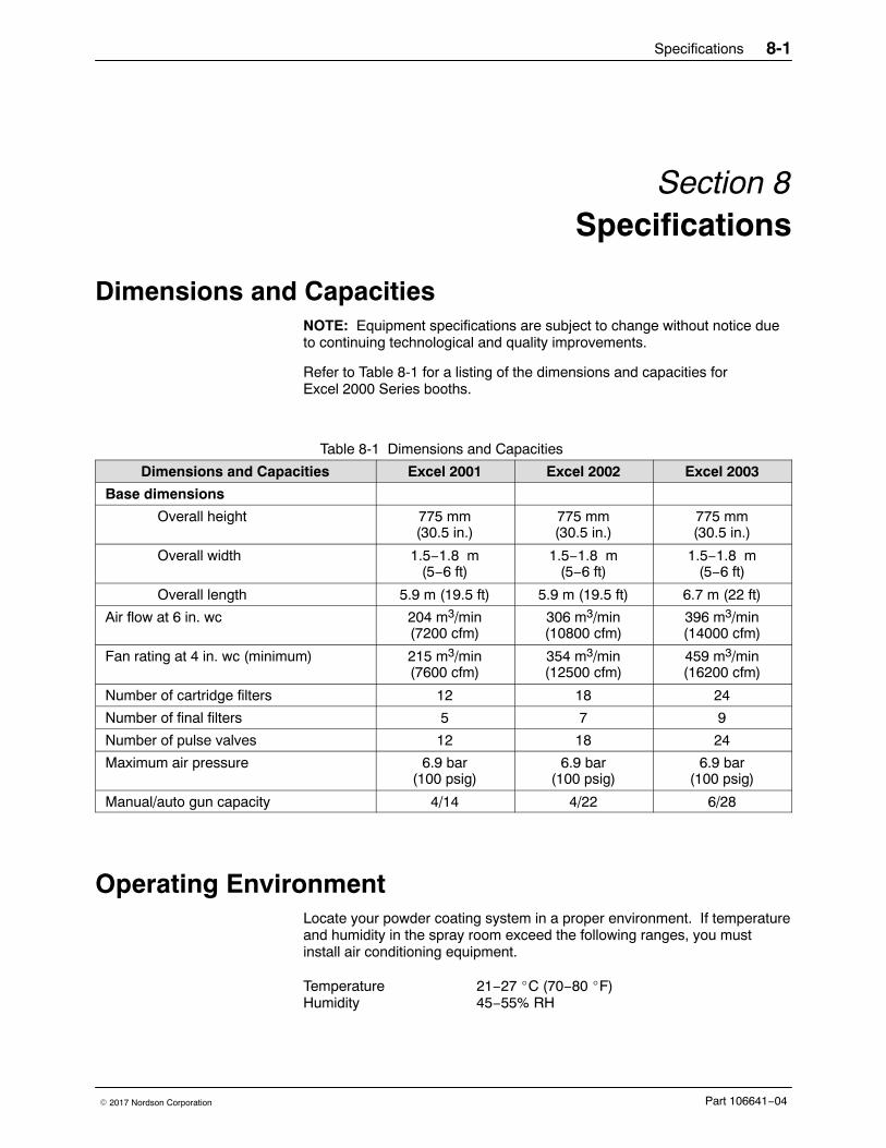
Specifications 8-1
Part 106641−04� 2017 Nordson Corporation
Section 8Specifications
Dimensions and CapacitiesNOTE: Equipment specifications are subject to change without notice dueto continuing technological and quality improvements.
Refer to Table 8-1 for a listing of the dimensions and capacities forExcel 2000 Series booths.
Table 8-1 Dimensions and Capacities
Dimensions and Capacities Excel 2001 Excel 2002 Excel 2003
Base dimensions
Overall height 775 mm(30.5 in.)
775 mm(30.5 in.)
775 mm(30.5 in.)
Overall width 1.5−1.8 m(5−6 ft)
1.5−1.8 m(5−6 ft)
1.5−1.8 m(5−6 ft)
Overall length 5.9 m (19.5 ft) 5.9 m (19.5 ft) 6.7 m (22 ft)
Air flow at 6 in. wc 204 m3/min(7200 cfm)
306 m3/min(10800 cfm)
396 m3/min(14000 cfm)
Fan rating at 4 in. wc (minimum) 215 m3/min(7600 cfm)
354 m3/min(12500 cfm)
459 m3/min(16200 cfm)
Number of cartridge filters 12 18 24
Number of final filters 5 7 9
Number of pulse valves 12 18 24
Maximum air pressure 6.9 bar(100 psig)
6.9 bar(100 psig)
6.9 bar(100 psig)
Manual/auto gun capacity 4/14 4/22 6/28
Operating EnvironmentLocate your powder coating system in a proper environment. If temperatureand humidity in the spray room exceed the following ranges, you mustinstall air conditioning equipment.
Temperature 21−27 �C (70−80 �F)Humidity 45−55% RH
Specifications8-2
Part 106641−04 � 2017 Nordson Corporation
UtilitiesPrimary Electrical Service: 230, 460, or 575 Vac. The customer mustinstall a fused disconnect switch with lock-out capability, wired inaccordance with the National Electric Code, NFPA-70.
Compressed Air Supply: The air supply line must be 38-mm (1.5-in.) IDminimum. Supply air pressure must be 5.5−6.9 bar (80−100 psi). The airmust be clean and dry.
Normal Design StandardsSystems are custom-designed to each customer’s requirements, so somemay deviate from these design standards. Contact your Nordsonrepresentative if you need more information about the design of your booth.
End Openings: 15.2 cm (6 in.) clearance on all four sides of the largestpart.
Part Hanger Keyhole Slot: 45.7 cm (18 in.) high.
Cross Drafts: No more than 18.3 m/min (60 FPM).
Average Face Velocity: No less than 30.5 m/min (100 FPM) through allopenings in the booth enclosure.
Temperature of Parts Entering Booth: No more than 49 �C (120 �F).
Powder: Use commercially available powder coatings. Note that thecharacteristics and properties of a powder coating can affect systemoperation. Powder coatings generally have an average particle size of25−35 microns, with no more than 10% of the total being less than15 microns. When the percentage of particles less than 15 micronsexceeds 10% of the total, the filter media can get clogged.
Cartridge Filters: Cartridge filters are considered wear items. Thevariables affecting the life expectancy of a cartridge filter include
� type of coating material
� particle size distribution
� humidity and temperature of the spray room air
� hours of operation
� dew point and cleanliness of the compressed air supply
� pressure and frequency of air pulses used to clean the filters
Compressed Air Supply: The air must be conditioned by adedicated, refrigerated or regenerative-desiccant air dryer that can producea 3 �C (38 �F) or lower dewpoint at 6.9 bar (100 psi).
Split Support Beam Installation 9-1
Part 106641−04� 2017 Nordson Corporation
Section 9Split Support Beam Installation
Split Support Beam Installation−Fixed Booths Use these instructions to install beam extensions on 152- and 183-cm(60- and 72-in.) fixed booths shipped with split support beams.
See Figure 9-1.
WARNING: Heavy equipment. Use approved, inspected lifting equipmentand tackle. Make sure the capacity of the lifting equipment and tackleexceeds the weight of the equipment being lifted.
1. Raise the booth base several feet off the floor, using a forklift truck,overhead crane, or suitable jack.
2. Install safe and solid support blocks under the booth base. The blocksshould support the base 60−90 cm (2−3 ft) off the floor. Lower the boothbase onto the blocks.
NOTE: Booths are shipped with the right and left support beams (1, 2)installed on the base.
3. Mount the right and left beam extensions (3, 4) to the end faces of thesupport beams, oriented as shown in Figure 9-1, with eight1/2-13 UNC cap screws, lock washers, and flat washers (7, 8, 9).
4. Square the beam extensions with the support beam end faces, thentighten the cap screws in a criss-cross pattern.
WARNING: Do not lower the base to the floor until all end and middle legsare installed. The weight of the base will not be properly supported unlessall legs are installed.
5. Install the end legs (6) and middle legs (5) to the support beams andbeam extensions as follows:
a. Install the end legs to the ends of the support beams opposite thebeam extensions with eight 3/8-16 UNC cap screws, lock washers,and flat washers (10, 11, 12).
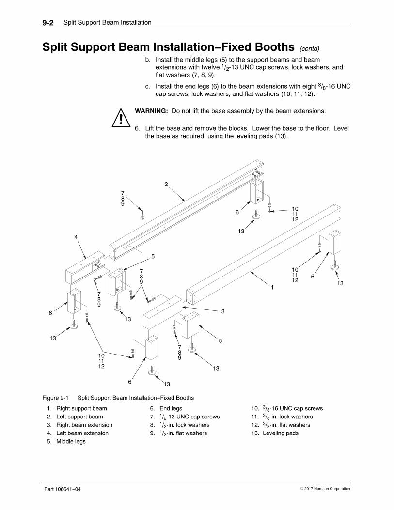
Split Support Beam Installation9-2
Part 106641−04 � 2017 Nordson Corporation
Split Support Beam Installation−Fixed Booths (contd)
b. Install the middle legs (5) to the support beams and beamextensions with twelve 1/2-13 UNC cap screws, lock washers, andflat washers (7, 8, 9).
c. Install the end legs (6) to the beam extensions with eight 3/8-16 UNCcap screws, lock washers, and flat washers (10, 11, 12).
WARNING: Do not lift the base assembly by the beam extensions.
6. Lift the base and remove the blocks. Lower the base to the floor. Levelthe base as required, using the leveling pads (13).
1
2
136
13
5
3
4
106
13
13
610
7
13
613
7
5
89
789
1112
101112
1112
89
789
Figure 9-1 Split Support Beam Installation−Fixed Booths
1. Right support beam2. Left support beam3. Right beam extension4. Left beam extension5. Middle legs
6. End legs7. 1/2-13 UNC cap screws8. 1/2-in. lock washers9. 1/2-in. flat washers
10. 3/8-16 UNC cap screws11. 3/8-in. lock washers12. 3/8-in. flat washers13. Leveling pads
Split Support Beam Installation 9-3
Part 106641−04� 2017 Nordson Corporation
Split Support Beam Installation−Roll-On/Roll-Off Booths
Use these instructions to install beam extensions on 152- and 183-cm(60- and 72-in.) roll-on/roll-off booths shipped with split support beams.
NOTE: If your booth is equipped with an Integral Booth Mover and splitsupport beams, refer to Split Support Beam Installation—Booths withIntegral Booth Mover for instructions to install split support beams.
See Figure 9-2.
WARNING: Heavy equipment. Use approved, inspected lifting equipmentand tackle. Make sure the capacity of the lifting equipment and tackleexceeds the weight of the equipment being lifted.
1. Raise the booth base several feet off the floor, using a forklift truck,overhead crane, or suitable jack.
2. Install safe and solid support blocks under the booth base. The blocksshould support the base 60−90 cm (2−3 ft) off the floor. Lower the boothbase onto the blocks.
NOTE: Booths are shipped with the right and left support beams (1, 2)installed on the base.
3. Mount the right and left beam extensions (3, 4) to the end faces of thesupport beams, oriented as shown in Figure 9-2, with eight1/2-13 UNC cap screws, lock washers, and flat washers (7, 8, 9).
4. Square the beam extensions with the support beam end faces, thentighten the cap screws in a criss-cross pattern.
NOTE: The casters (6) are shipped installed on the secondary supportbeams.
5. Install the right and left secondary support beams (5) to the base supportbeams, oriented as shown in Figure 9-2, with eight 1/2−13 UNC cap screws,lock washers, and flat washers (7, 8, 9).
WARNING: Do not lift the booth base by the beam extensions.
6. Lift the base and remove the blocks. Lower the casters onto the rollertracks. Level the base as required.
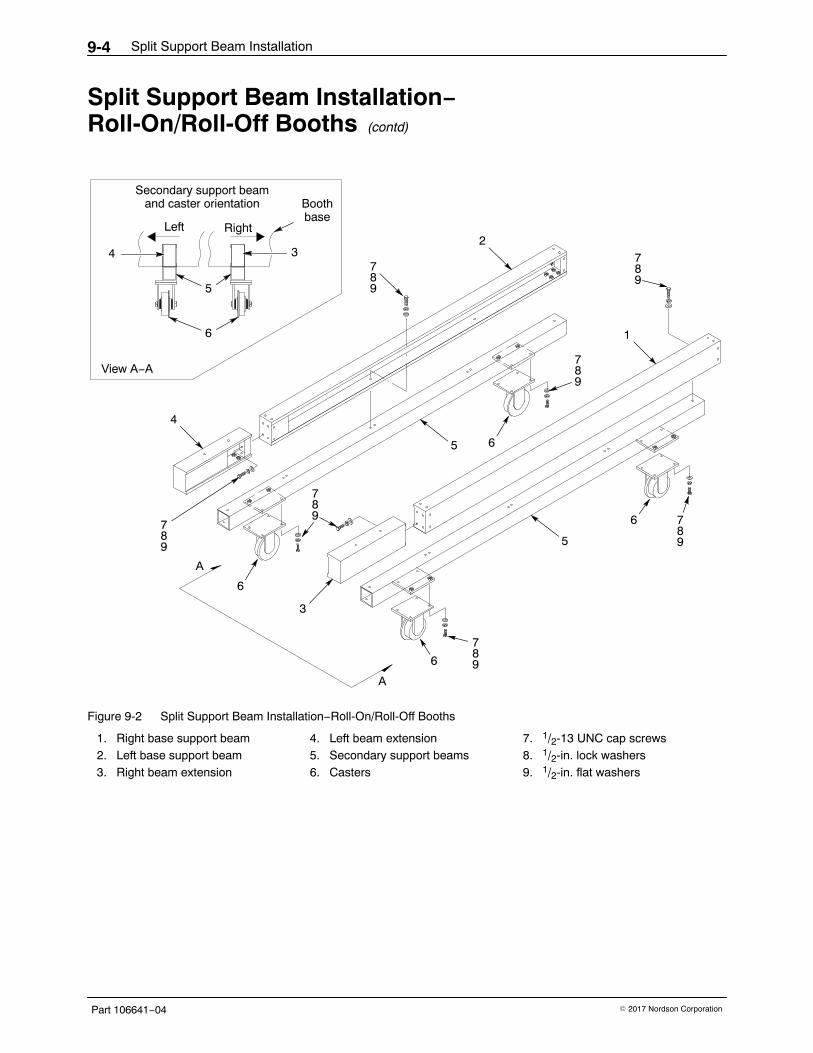
Split Support Beam Installation9-4
Part 106641−04 � 2017 Nordson Corporation
Split Support Beam Installation−Roll-On/Roll-Off Booths (contd)
Secondary support beamand caster orientation
Left Right
Boothbase
View A−A
4
A
A
6
5
4
32
7
6
3
7
7
7
7
5
5
1
89
898
9
89
89
789
6
789
6
6
Figure 9-2 Split Support Beam Installation−Roll-On/Roll-Off Booths
1. Right base support beam2. Left base support beam3. Right beam extension
4. Left beam extension5. Secondary support beams6. Casters
7. 1/2-13 UNC cap screws8. 1/2-in. lock washers9. 1/2-in. flat washers

Split Support Beam Installation 9-5
Part 106641−04� 2017 Nordson Corporation
Split Support Beam Installation−Booths with Integral Booth Mover
Use these instructions to install beam extensions on 152- and 183-cm (60-and 72-in.) booths shipped with an Integral Booth Mover and split supportbeams.
See Figure 9-3.
WARNING: Heavy equipment. Use approved, inspected lifting equipmentand tackle. Make sure the capacity of the lifting equipment and tackleexceeds the weight of the equipment being lifted.
1. Raise the booth base several feet off the floor, using a forklift truck,overhead crane, or suitable jack.
2. Install safe and solid support blocks under the booth base. The blocksshould support the base 60−90 cm (2−3 ft) off the floor. Lower the boothbase onto the blocks.
NOTE: Booths are shipped with the right and left support beams (1, 2)installed on the base.
3. Mount the right and left beam extensions (3, 4) to the end faces of thesupport beams, oriented as shown in Figure 9-3, with eight1/2-13 UNC cap screws, lock washers, and flat washers (5, 6, 7).
4. Square the beam extensions with the support beam end faces, thentighten the cap screws in a criss-cross pattern.
5. Install the Integral Booth Mover.
WARNING: Do not lift the booth base by the beam extensions.
6. Lift the base and remove the blocks. Lower the casters onto the rollertracks. Level the base as required.
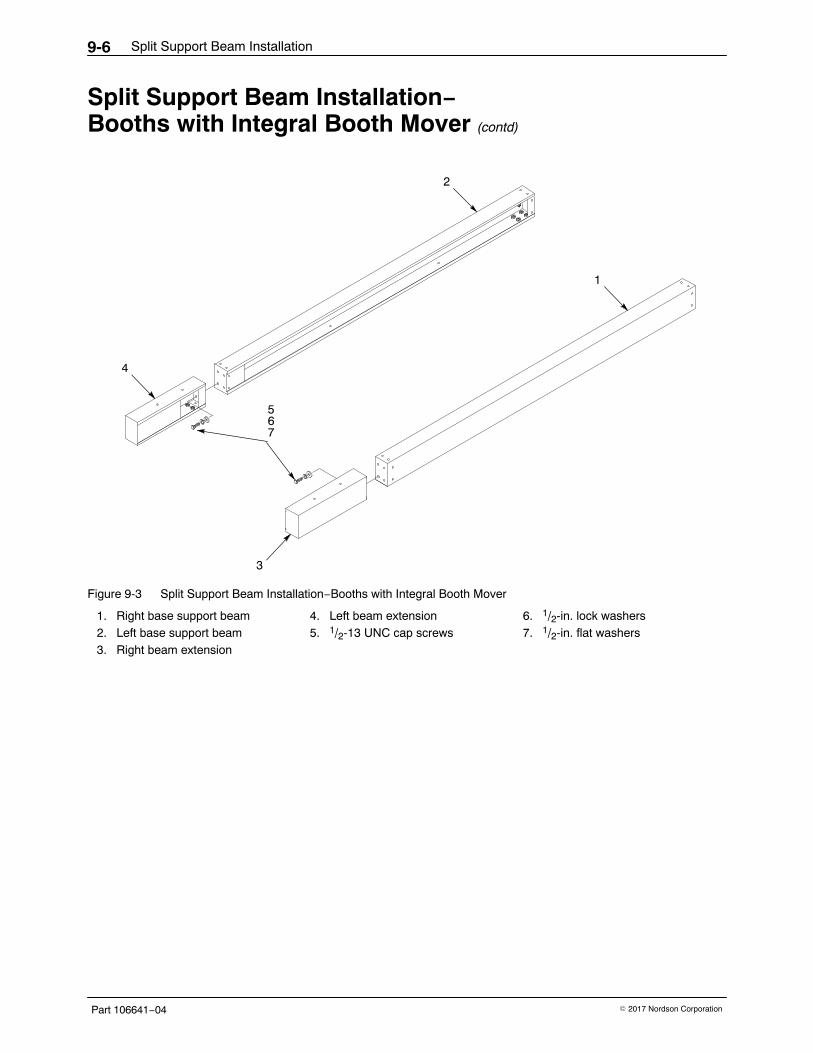
Split Support Beam Installation9-6
Part 106641−04 � 2017 Nordson Corporation
Split Support Beam Installation−Booths with Integral Booth Mover (contd)
4
2
3
5
1
67
Figure 9-3 Split Support Beam Installation−Booths with Integral Booth Mover
1. Right base support beam2. Left base support beam3. Right beam extension
4. Left beam extension5. 1/2-13 UNC cap screws
6. 1/2-in. lock washers7. 1/2-in. flat washers
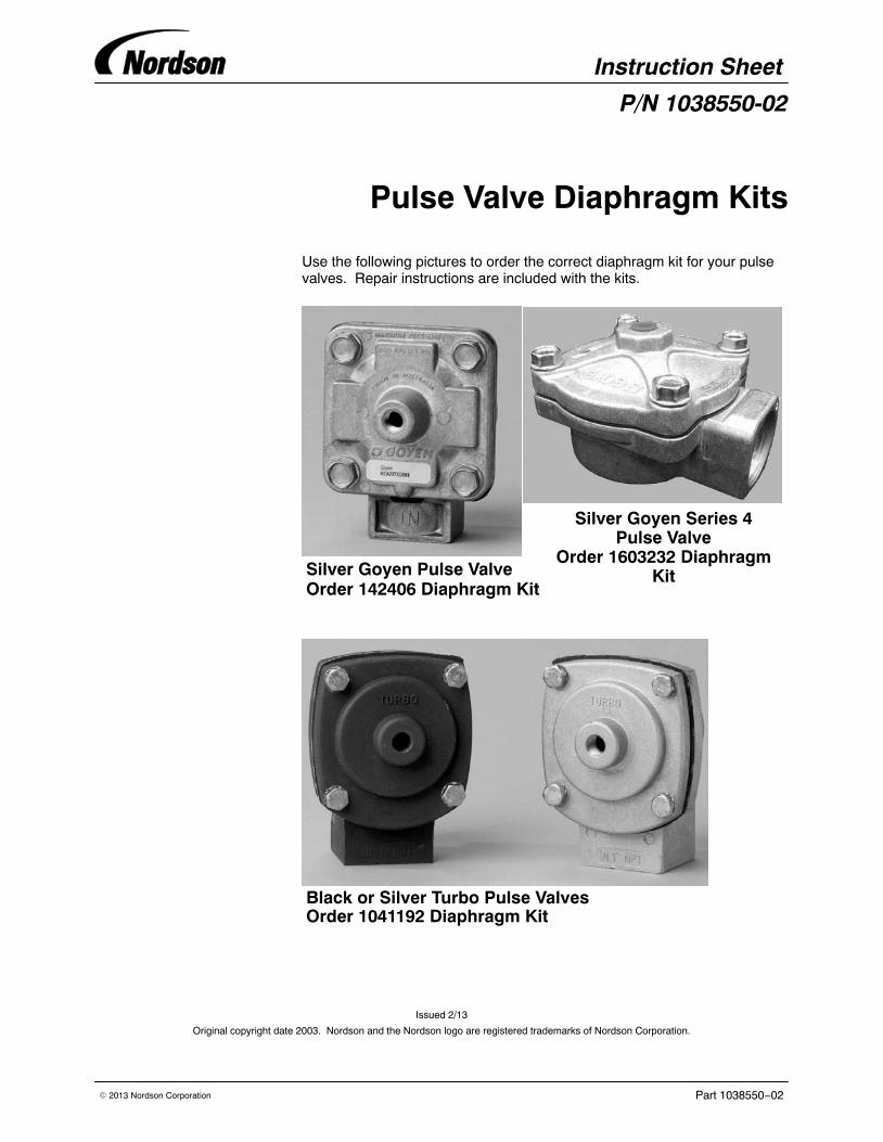
Instruction Sheet
Part 1038550−02� 2013 Nordson Corporation
P/N 1038550-02
Pulse Valve Diaphragm Kits
Use the following pictures to order the correct diaphragm kit for your pulsevalves. Repair instructions are included with the kits.
Order 142406 Diaphragm KitSilver Goyen Pulse Valve
Silver Goyen Series 4Pulse Valve
Order 1603232 DiaphragmKit
Black or Silver Turbo Pulse ValvesOrder 1041192 Diaphragm Kit
Issued 2/13
Original copyright date 2003. Nordson and the Nordson logo are registered trademarks of Nordson Corporation.
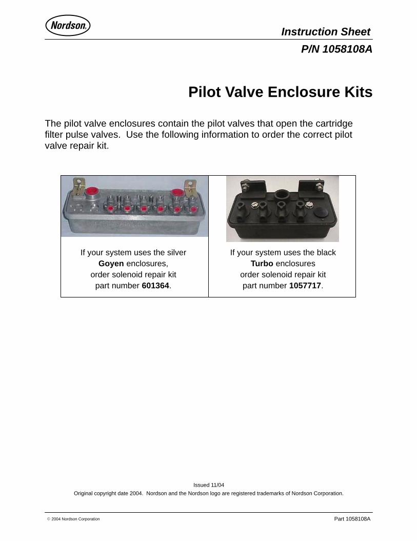
Instruction Sheet
Part 1058108A� 2004 Nordson Corporation
P/N 1058108A
Pilot Valve Enclosure Kits
The pilot valve enclosures contain the pilot valves that open the cartridgefilter pulse valves. Use the following information to order the correct pilotvalve repair kit.
If your system uses the blackTurbo enclosures
order solenoid repair kitpart number 1057717.
If your system uses the silverGoyen enclosures,
order solenoid repair kitpart number 601364.
Issued 11/04
Original copyright date 2004. Nordson and the Nordson logo are registered trademarks of Nordson Corporation.