Embed Size (px)
Citation preview
Encore� HDManual Powder Spray Gun
Customer Product ManualPart 1604869-11
Issued 04/18
NORDSON CORPORATION • AMHERST, OHIO • USA
For parts and technical support, call theIndustrial Coating Systems Customer Support Center
at (800) 433-9319 or contact your local Nordson representative.
This document is subject to change without notice.Check http://emanuals.nordson.com/finishing for the latest version
and available local languages.

Part 1604869-11 � 2018 Nordson Corporation
Contact UsNordson Corporation welcomes requests for information, comments, andinquiries about its products. General information about Nordson can befound on the Internet using the following address:http://www.nordson.com.Address all correspondence to:
Nordson CorporationAttn: Customer Service555 Jackson StreetAmherst, OH 44001
NoticeThis is a Nordson Corporation publication which is protected by copyright.Original copyright date 2014. No part of this document may bephotocopied, reproduced, or translated to another language without theprior written consent of Nordson Corporation. The information containedin this publication is subject to change without notice.
Trademarks
ColorMax, Color-on-Demand, Encore, HDLV, iControl, Prodigy, Nordson,and the Nordson logo are registered trademarks of Nordson Corporation.
All other trademarks are the property of their respective owners.
Change Record i
Part 1604869-11� 2018 Nordson Corporation
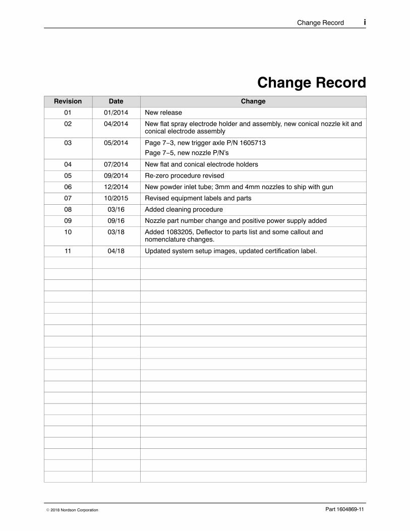
Change RecordRevision Date Change
01 01/2014 New release
02 04/2014 New flat spray electrode holder and assembly, new conical nozzle kit andconical electrode assembly
03 05/2014 Page 7−3, new trigger axle P/N 1605713
Page 7−5, new nozzle P/N’s
04 07/2014 New flat and conical electrode holders
05 09/2014 Re-zero procedure revised
06 12/2014 New powder inlet tube; 3mm and 4mm nozzles to ship with gun
07 10/2015 Revised equipment labels and parts
08 03/16 Added cleaning procedure
09 09/16 Nozzle part number change and positive power supply added
10 03/18 Added 1083205, Deflector to parts list and some callout andnomenclature changes.
11 04/18 Updated system setup images, updated certification label.
Change Recordii
Part 1604869-11 � 2018 Nordson Corporation
Table of Contents iii
Part 1604869-11� 2018 Nordson Corporation
Table of Contents
Safety 1-1. . . . . . . . . . . . . . . . . . . . . . . . . . . . . . . . . . . . . . . . . . . . . . . . . .Introduction 1-1. . . . . . . . . . . . . . . . . . . . . . . . . . . . . . . . . . . . . . . . . . . . .Qualified Personnel 1-1. . . . . . . . . . . . . . . . . . . . . . . . . . . . . . . . . . . . . .Intended Use 1-1. . . . . . . . . . . . . . . . . . . . . . . . . . . . . . . . . . . . . . . . . . .Regulations and Approvals 1-1. . . . . . . . . . . . . . . . . . . . . . . . . . . . . . .Personal Safety 1-2. . . . . . . . . . . . . . . . . . . . . . . . . . . . . . . . . . . . . . . . .Fire Safety 1-2. . . . . . . . . . . . . . . . . . . . . . . . . . . . . . . . . . . . . . . . . . . . .Grounding 1-3. . . . . . . . . . . . . . . . . . . . . . . . . . . . . . . . . . . . . . . . . . . . . .Action in the Event of a Malfunction 1-3. . . . . . . . . . . . . . . . . . . . . . . .Disposal 1-3. . . . . . . . . . . . . . . . . . . . . . . . . . . . . . . . . . . . . . . . . . . . . . .
Description 2-1. . . . . . . . . . . . . . . . . . . . . . . . . . . . . . . . . . . . . . . . . . . . .Introduction 2-1. . . . . . . . . . . . . . . . . . . . . . . . . . . . . . . . . . . . . . . . . . . . .Specifications 2-2. . . . . . . . . . . . . . . . . . . . . . . . . . . . . . . . . . . . . . . . . . .Equipment Labels 2-2. . . . . . . . . . . . . . . . . . . . . . . . . . . . . . . . . . . . . . .
Applicator Certification Label 2-2. . . . . . . . . . . . . . . . . . . . . . . . . . .
Setup 3-1. . . . . . . . . . . . . . . . . . . . . . . . . . . . . . . . . . . . . . . . . . . . . . . . . .System Connections 3-1. . . . . . . . . . . . . . . . . . . . . . . . . . . . . . . . . . . . .
Spray Gun Installation 3-2. . . . . . . . . . . . . . . . . . . . . . . . . . . . . . . . . .
Operation 4-1. . . . . . . . . . . . . . . . . . . . . . . . . . . . . . . . . . . . . . . . . . . . . .European Union, ATEX, Special Conditions for Safe Use 4-1. . . . . .System Operation 4-2. . . . . . . . . . . . . . . . . . . . . . . . . . . . . . . . . . . . . . .Spray Gun Operation 4-2. . . . . . . . . . . . . . . . . . . . . . . . . . . . . . . . . . . .
Changing Presets with the Settings Trigger 4-2. . . . . . . . . . . . . . .Changing Powder Flow with the Settings Trigger 4-3. . . . . . . . . .Purging the Spray Gun 4-3. . . . . . . . . . . . . . . . . . . . . . . . . . . . . . . .
Electrode Air Wash Operation 4-4. . . . . . . . . . . . . . . . . . . . . . . . . . . . .Daily Operation 4-4. . . . . . . . . . . . . . . . . . . . . . . . . . . . . . . . . . . . . . . . .
Initial Startup 4-4. . . . . . . . . . . . . . . . . . . . . . . . . . . . . . . . . . . . . . . . .Startup 4-4. . . . . . . . . . . . . . . . . . . . . . . . . . . . . . . . . . . . . . . . . . . . . .Standby Button 4-4. . . . . . . . . . . . . . . . . . . . . . . . . . . . . . . . . . . . . . .Changing Flat Spray Nozzles 4-5. . . . . . . . . . . . . . . . . . . . . . . . . . .Converting from Flat Spray Nozzles to Conical Nozzles 4-6. . . .Changing Deflectors or Conical Nozzles 4-7. . . . . . . . . . . . . . . . . .Installing the Optional Pattern Adjuster Kit 4-8. . . . . . . . . . . . . . . .
Shutdown 4-8. . . . . . . . . . . . . . . . . . . . . . . . . . . . . . . . . . . . . . . . . . . . . . .Maintenance 4-8. . . . . . . . . . . . . . . . . . . . . . . . . . . . . . . . . . . . . . . . . . . .
Recommended Cleaning Procedure forPowder Contact Parts 4-9. . . . . . . . . . . . . . . . . . . . . . . . . . . . . . . . .Maintenance Procedures 4-9. . . . . . . . . . . . . . . . . . . . . . . . . . . . . . .
Table of Contentsiv
Part 1604869-11 � 2018 Nordson Corporation
Repair 5-1. . . . . . . . . . . . . . . . . . . . . . . . . . . . . . . . . . . . . . . . . . . . . . . . .Spray Gun Repair 5-1. . . . . . . . . . . . . . . . . . . . . . . . . . . . . . . . . . . . . . .
Display Module Replacement 5-2. . . . . . . . . . . . . . . . . . . . . . . . . . .Display Module Removal 5-2. . . . . . . . . . . . . . . . . . . . . . . . . . . .Display Module Installation 5-2. . . . . . . . . . . . . . . . . . . . . . . . . . .
Power Supply and Powder Path Replacement 5-4. . . . . . . . . . . .Gun Disassembly 5-4. . . . . . . . . . . . . . . . . . . . . . . . . . . . . . . . . . .Power Supply Replacement 5-5. . . . . . . . . . . . . . . . . . . . . . . . . .Powder Path Removal 5-6. . . . . . . . . . . . . . . . . . . . . . . . . . . . . .Powder Path Installation 5-6. . . . . . . . . . . . . . . . . . . . . . . . . . . . .Gun Re-Assembly 5-8. . . . . . . . . . . . . . . . . . . . . . . . . . . . . . . . . .
Cable Replacement 5-9. . . . . . . . . . . . . . . . . . . . . . . . . . . . . . . . . . .Cable Removal 5-9. . . . . . . . . . . . . . . . . . . . . . . . . . . . . . . . . . . . .Cable Installation 5-10. . . . . . . . . . . . . . . . . . . . . . . . . . . . . . . . . . .
Trigger Switch Replacement 5-10. . . . . . . . . . . . . . . . . . . . . . . . . . . .Switch Removal 5-10. . . . . . . . . . . . . . . . . . . . . . . . . . . . . . . . . . . .Switch Installation 5-11. . . . . . . . . . . . . . . . . . . . . . . . . . . . . . . . . .
Troubleshooting 6-1. . . . . . . . . . . . . . . . . . . . . . . . . . . . . . . . . . . . . . . .Spray Gun Power Supply Resistance Test 6-2. . . . . . . . . . . . . . . . . .Electrode Assembly Resistance Test 6-2. . . . . . . . . . . . . . . . . . . . . . .Gun Cable Continuity Test 6-3. . . . . . . . . . . . . . . . . . . . . . . . . . . . . . . .
Parts 7-1. . . . . . . . . . . . . . . . . . . . . . . . . . . . . . . . . . . . . . . . . . . . . . . . . . .Introduction 7-1. . . . . . . . . . . . . . . . . . . . . . . . . . . . . . . . . . . . . . . . . . . . .Spray Gun Parts 7-1. . . . . . . . . . . . . . . . . . . . . . . . . . . . . . . . . . . . . . . .
Spray Gun Parts Illustration 7-2. . . . . . . . . . . . . . . . . . . . . . . . . . . .Spray Gun Parts List 7-3. . . . . . . . . . . . . . . . . . . . . . . . . . . . . . . . . .
Spray Gun Options 7-5. . . . . . . . . . . . . . . . . . . . . . . . . . . . . . . . . . . . . .Miscellaneous Spray Gun Options 7-5. . . . . . . . . . . . . . . . . . . . . . .Flat Spray Nozzles 7-5. . . . . . . . . . . . . . . . . . . . . . . . . . . . . . . . . . . .Cross Cut Nozzles 7-5. . . . . . . . . . . . . . . . . . . . . . . . . . . . . . . . . . . .45-Degree Corner-Spray Nozzle 7-6. . . . . . . . . . . . . . . . . . . . . . . . .45-Degree In-Line Flat-Spray Nozzle 7-6. . . . . . . . . . . . . . . . . . . .Conical Nozzle, Deflectors and Electrode Assembly Parts 7-7. . .
Conical Nozzle and Deflectors 7-7. . . . . . . . . . . . . . . . . . . . . . . .Conical Nozzle Kit (shipped with gun) 7-7. . . . . . . . . . . . . . . . . .Conical Electrode Assembly 7-8. . . . . . . . . . . . . . . . . . . . . . . . . .
Pattern Adjuster Kit 7-8. . . . . . . . . . . . . . . . . . . . . . . . . . . . . . . . . . .Lance Extensions 7-8. . . . . . . . . . . . . . . . . . . . . . . . . . . . . . . . . . . . .Ion Collector Kit 7-9. . . . . . . . . . . . . . . . . . . . . . . . . . . . . . . . . . . . . . .Ion Collector Components for Lance Extensions 7-9. . . . . . . . . .Powder Hose and Air Tubing 7-9. . . . . . . . . . . . . . . . . . . . . . . . . . .
Safety 1-1
Part 1604869-11� 2018 Nordson Corporation
Section 1Safety
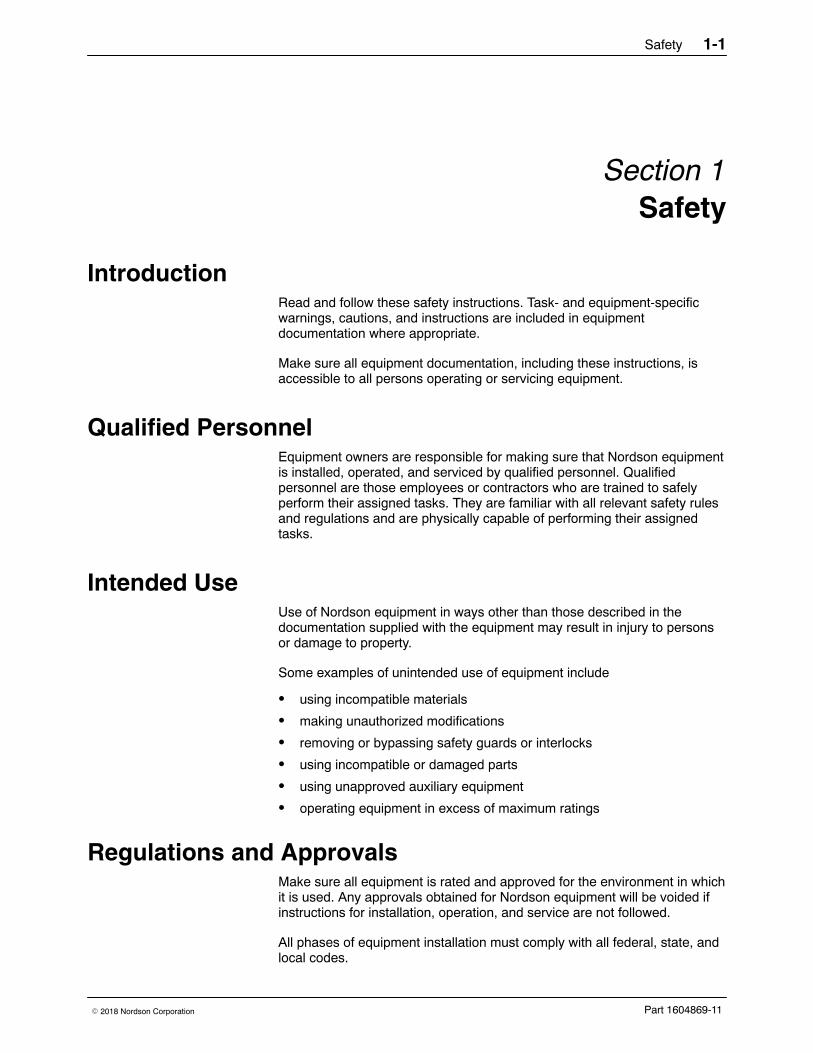
Introduction Read and follow these safety instructions. Task- and equipment-specificwarnings, cautions, and instructions are included in equipmentdocumentation where appropriate.
Make sure all equipment documentation, including these instructions, isaccessible to all persons operating or servicing equipment.
Qualified Personnel Equipment owners are responsible for making sure that Nordson equipmentis installed, operated, and serviced by qualified personnel. Qualifiedpersonnel are those employees or contractors who are trained to safelyperform their assigned tasks. They are familiar with all relevant safety rulesand regulations and are physically capable of performing their assignedtasks.
Intended Use Use of Nordson equipment in ways other than those described in thedocumentation supplied with the equipment may result in injury to personsor damage to property.
Some examples of unintended use of equipment include
� using incompatible materials
� making unauthorized modifications
� removing or bypassing safety guards or interlocks
� using incompatible or damaged parts
� using unapproved auxiliary equipment
� operating equipment in excess of maximum ratings
Regulations and Approvals Make sure all equipment is rated and approved for the environment in whichit is used. Any approvals obtained for Nordson equipment will be voided ifinstructions for installation, operation, and service are not followed.
All phases of equipment installation must comply with all federal, state, andlocal codes.
Safety1-2
Part 1604869-11 � 2018 Nordson Corporation
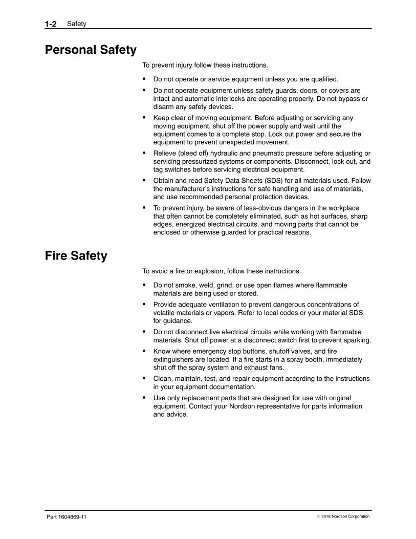
Personal Safety To prevent injury follow these instructions.
� Do not operate or service equipment unless you are qualified.
� Do not operate equipment unless safety guards, doors, or covers areintact and automatic interlocks are operating properly. Do not bypass ordisarm any safety devices.
� Keep clear of moving equipment. Before adjusting or servicing anymoving equipment, shut off the power supply and wait until theequipment comes to a complete stop. Lock out power and secure theequipment to prevent unexpected movement.
� Relieve (bleed off) hydraulic and pneumatic pressure before adjusting orservicing pressurized systems or components. Disconnect, lock out, andtag switches before servicing electrical equipment.
� Obtain and read Safety Data Sheets (SDS) for all materials used. Followthe manufacturer’s instructions for safe handling and use of materials,and use recommended personal protection devices.
� To prevent injury, be aware of less-obvious dangers in the workplacethat often cannot be completely eliminated, such as hot surfaces, sharpedges, energized electrical circuits, and moving parts that cannot beenclosed or otherwise guarded for practical reasons.
Fire Safety To avoid a fire or explosion, follow these instructions.
� Do not smoke, weld, grind, or use open flames where flammablematerials are being used or stored.
� Provide adequate ventilation to prevent dangerous concentrations ofvolatile materials or vapors. Refer to local codes or your material SDSfor guidance.
� Do not disconnect live electrical circuits while working with flammablematerials. Shut off power at a disconnect switch first to prevent sparking.
� Know where emergency stop buttons, shutoff valves, and fireextinguishers are located. If a fire starts in a spray booth, immediatelyshut off the spray system and exhaust fans.
� Clean, maintain, test, and repair equipment according to the instructionsin your equipment documentation.
� Use only replacement parts that are designed for use with originalequipment. Contact your Nordson representative for parts informationand advice.
Safety 1-3
Part 1604869-11� 2018 Nordson Corporation
Grounding WARNING: Operating faulty electrostatic equipment is hazardous and cancause electrocution, fire, or explosion. Make resistance checks part of yourperiodic maintenance program. If you receive even a slight electrical shockor notice static sparking or arcing, shut down all electrical or electrostaticequipment immediately. Do not restart the equipment until the problem hasbeen identified and corrected.
Grounding inside and around the booth openings must comply with NFPArequirements for Class II, Division 1 or 2 Hazardous Locations. Refer toNFPA 33, NFPA 70 (NEC articles 500, 502, and 516), and NFPA 77, latestconditions.
� All electrically conductive objects in the spray areas shall be electricallyconnected to ground with a resistance of not more than 1 megohm asmeasured with an instrument that applies at least 500 volts to the circuitbeing evaluated.
� Equipment to be grounded includes, but is not limited to, the floor of thespray area, operator platforms, hoppers, photoeye supports, andblow-off nozzles. Personnel working in the spray area must begrounded.
� There is a possible ignition potential from the charged human body.Personnel standing on a painted surface, such as an operator platform,or wearing non-conductive shoes, are not grounded. Personnel mustwear shoes with conductive soles or use a ground strap to maintain aconnection to ground when working with or around electrostaticequipment.
� Operators must maintain skin-to-handle contact between their hand andthe gun handle to prevent shocks while operating manual electrostaticspray guns. If gloves must be worn, cut away the palm or fingers, wearelectrically conductive gloves, or wear a grounding strap connected tothe gun handle or other true earth ground.
� Shut off electrostatic power supplies and ground gun electrodes beforemaking adjustments or cleaning powder spray guns.
� Connect all disconnected equipment, ground cables, and wires afterservicing equipment.
Action in the Event of a Malfunction If a system or any equipment in a system malfunctions, shut off the systemimmediately and perform the following steps:
� Disconnect and lock out electrical power. Close pneumatic shutoffvalves and relieve pressures.
� Identify the reason for the malfunction and correct it before restarting theequipment.
Disposal Dispose of equipment and materials used in operation and servicingaccording to local codes.
Safety1-4
Part 1604869-11 � 2018 Nordson Corporation
Description 2-1
Part 1604869-11� 2018 Nordson Corporation
Section 2Description
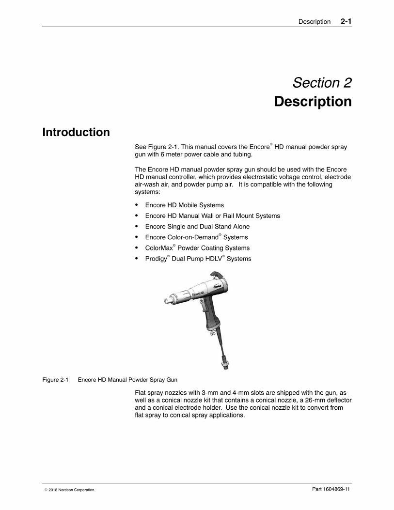
Introduction See Figure 2-1. This manual covers the Encore� HD manual powder spraygun with 6 meter power cable and tubing.
The Encore HD manual powder spray gun should be used with the EncoreHD manual controller, which provides electrostatic voltage control, electrodeair-wash air, and powder pump air. It is compatible with the followingsystems:
� Encore HD Mobile Systems
� Encore HD Manual Wall or Rail Mount Systems
� Encore Single and Dual Stand Alone
� Encore Color-on-Demand� Systems
� ColorMax� Powder Coating Systems
� Prodigy� Dual Pump HDLV� Systems
Figure 2-1 Encore HD Manual Powder Spray Gun
Flat spray nozzles with 3-mm and 4-mm slots are shipped with the gun, aswell as a conical nozzle kit that contains a conical nozzle, a 26-mm deflectorand a conical electrode holder. Use the conical nozzle kit to convert fromflat spray to conical spray applications.
Description2-2
Part 1604869-11 � 2018 Nordson Corporation
Optional equipment is available for the Encore HD manual spray gunincluding the following:
� Additional flat, conical and cross-cut nozzles options
� 6-meter cable extension
� 150 and 300-mm lance extensions
� Pattern adjuster for use with lance extensions
� Ion collector
See Options section beginning on page 7-5 for information on additionaloptions.
Specifications Model: Encore Applicator
Input Rating: +/− 19 VAC, 1 A
Output Rating: 100 KV, 100 μA
Input Air: 6.0−7.6 bar (87−110 psi), <5μ particulates,dew point <10 �C (50 �F)
Max Relative Humidity: 95% non-Condensing
Ambient Temperature Rating: +15 to +40 �C
(59−104 �F)
Hazardous Location Rating for Applicator: Zone 21 or Class II, Division 1
Dust Ingress Protection: IP6X
Equipment Labels
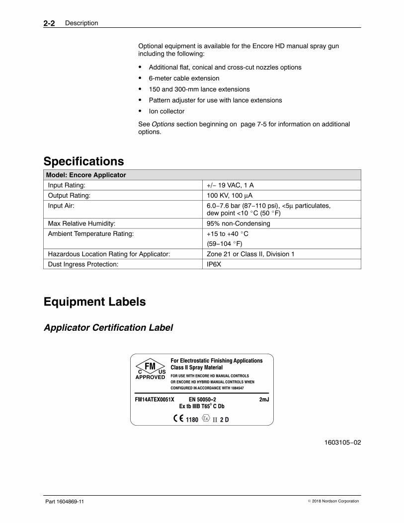
Applicator Certification Label
1180 II 2 D
EN 50050-2OEx tb IIIB T65 C Db
FM14ATEX0051X 2mJ
FMC US
APPROVED
For Electrostatic Finishing ApplicationsClass II Spray MaterialFOR USE WITH ENCORE HD MANUAL CONTROLS
OR ENCORE HD HYBRID MANUAL CONTROLS WHEN
CONFIGURED IN ACCORDANCE WITH 1084547
1603105−02
Setup 3-1
Part 1604869-11� 2018 Nordson Corporation
Section 3Setup
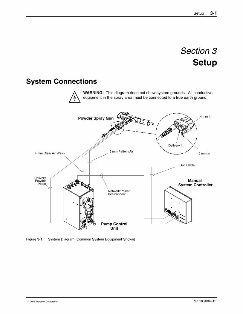
System ConnectionsWARNING: This diagram does not show system grounds. All conductiveequipment in the spray area must be connected to a true earth ground.
Powder Spray Gun
Pump ControlUnit
Manual System Controller
Gun Cable
6 mm Pattern Air
Delivery
4 mm Clear Air Wash
Network/PowerInterconnect
4 mm In
6 mm In
Delivery In
HosePowder
Figure 3-1 System Diagram (Common System Equipment Shown)
Setup3-2
Part 1604869-11 � 2018 Nordson Corporation
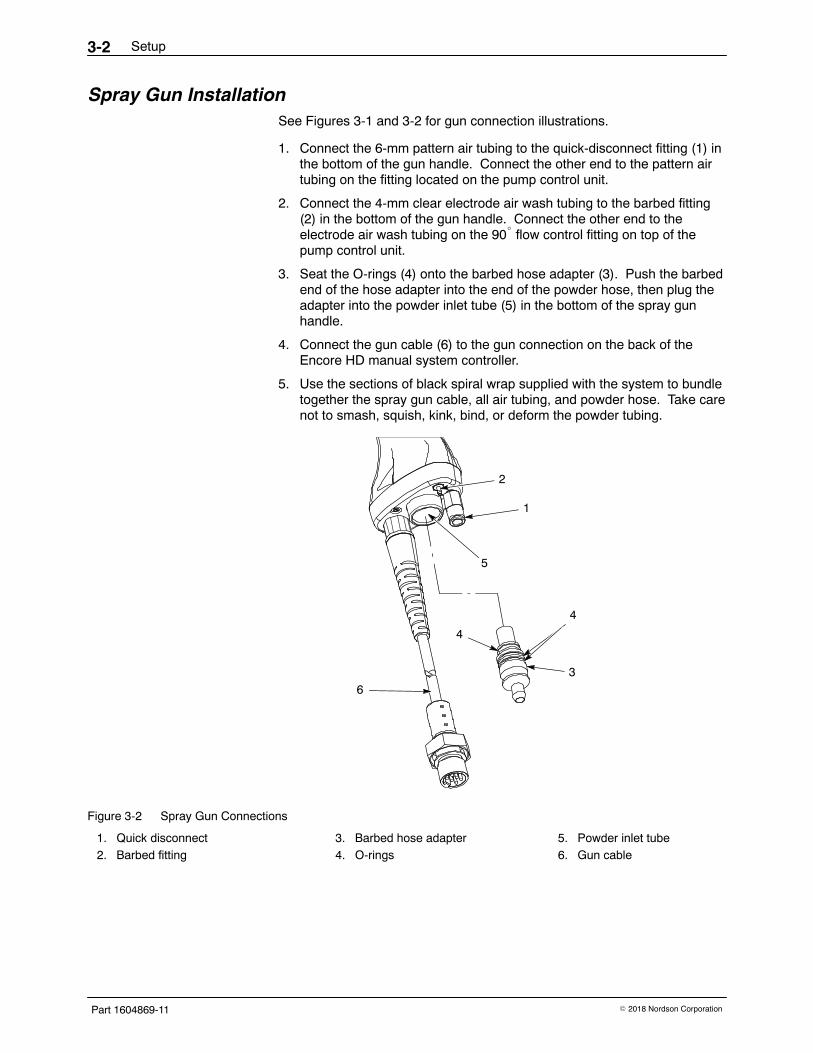
Spray Gun InstallationSee Figures 3-1 and 3-2 for gun connection illustrations.
1. Connect the 6-mm pattern air tubing to the quick-disconnect fitting (1) inthe bottom of the gun handle. Connect the other end to the pattern airtubing on the fitting located on the pump control unit.
2. Connect the 4-mm clear electrode air wash tubing to the barbed fitting(2) in the bottom of the gun handle. Connect the other end to theelectrode air wash tubing on the 90� flow control fitting on top of thepump control unit.
3. Seat the O-rings (4) onto the barbed hose adapter (3). Push the barbedend of the hose adapter into the end of the powder hose, then plug theadapter into the powder inlet tube (5) in the bottom of the spray gunhandle.
4. Connect the gun cable (6) to the gun connection on the back of theEncore HD manual system controller.
5. Use the sections of black spiral wrap supplied with the system to bundletogether the spray gun cable, all air tubing, and powder hose. Take carenot to smash, squish, kink, bind, or deform the powder tubing.
1
3
4
6
5
2
4
Figure 3-2 Spray Gun Connections
1. Quick disconnect2. Barbed fitting
3. Barbed hose adapter4. O-rings
5. Powder inlet tube6. Gun cable
Operation 4-1
Part 1604869-11� 2018 Nordson Corporation
Section 4Operation
WARNING: Allow only qualified personnel to perform the following tasks.Follow the safety instructions in this document and all other relateddocumentation.
WARNING: This equipment can be dangerous unless it is used accordancewith the rules laid down in this manual.
WARNING: All electrically conductive equipment in the spray area must begrounded. Ungrounded or poorly grounded equipment can store anelectrostatic charge which can give personnel a severe shock or arc andcause a fire or explosion.
European Union, ATEX, Special Conditions for Safe Use1. The Encore HD manual applicator shall only be used with the associated
Encore XT/HD interface control unit and Encore HD controller powerunit, over the ambient temperature range of +15 �C to +40 �C.
2. Equipment may only be used in areas of low impact risk.
3. Caution should be taken when cleaning plastic surfaces of the Encorecontroller and interface. There is a potential for static electricity build upon these components.
Operation4-2
Part 1604869-11 � 2018 Nordson Corporation
System Operation This manual includes information on the Encore HD Manual Powder SprayGun. Refer to appropriate system, controller and control panel manuals forinformation on system components.
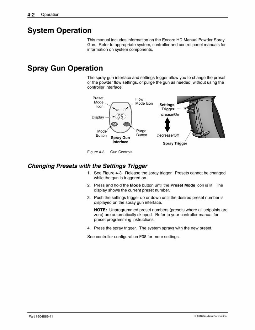
Spray Gun Operation The spray gun interface and settings trigger allow you to change the presetor the powder flow settings, or purge the gun as needed, without using thecontroller interface.
ModeButton
PresetMode
Icon
FlowMode Icon
PurgeButton
DisplayIncrease/On
Decrease/OffSpray GunInterface
SettingsTrigger
Spray Trigger
Figure 4-3 Gun Controls
Changing Presets with the Settings Trigger 1. See Figure 4-3. Release the spray trigger. Presets cannot be changed
while the gun is triggered on.
2. Press and hold the Mode button until the Preset Mode icon is lit. Thedisplay shows the current preset number.
3. Push the settings trigger up or down until the desired preset number isdisplayed on the spray gun interface.
NOTE: Unprogrammed preset numbers (presets where all setpoints arezero) are automatically skipped. Refer to your controller manual forpreset programming instructions.
4. Press the spray trigger. The system sprays with the new preset.
See controller configuration F08 for more settings.
Operation 4-3
Part 1604869-11� 2018 Nordson Corporation
Changing Powder Flow with the Settings Trigger 1. See Figure 4-3. Press and hold the Mode button until the Flow Mode
icon is lit.
2. Push the settings trigger up or down to change the flow setpoint. Thiscan be done without releasing the spray trigger.
The powder flow immediately changes. The new flow setpoint isdisplayed on both the spray gun interface and the controller interface.
Purging the Spray Gun 1. See Figure 4-3. Point the gun into the booth and release the spray
trigger.
2. Press and hold the Purge button. The purge will continue as long asyou hold the Purge button.
NOTE: If the settings trigger is configured for Purge, then pressing up ordown on the settings trigger purges the gun. Refer to ControllerConfiguration in your controller manual for setting trigger configuration.
For optimal performance, purge the gun periodically to keep the powderpath inside the spray gun clean. The purge length and frequency requiredwill depend on the application.
NOTE: The purge air only cleans the spray gun powder path. Refer to thesystem controller manual for additional HDLV purge information.
Operation4-4
Part 1604869-11 � 2018 Nordson Corporation
Electrode Air Wash Operation Electrode air wash air continually washes the spray gun electrode toprevent powder from collecting on it. Electrode air wash air turns on and offautomatically when the spray gun is triggered on and off.
Refer to the pump control unit manual for instructions on adjusting electrodeair wash flow.
Daily Operation WARNING: All conductive equipment in the spray area must be connectedto a true earth ground. Failure to observe this warning may result in asevere shock.
Initial Startup With the fluidizing and powder flow set to zero, and no parts in front of thegun, trigger the gun and record the μA output. Monitor the μA output daily,under the same conditions. A significant increase in μA output indicates aprobable short in the gun resistor. A significant decrease indicates aresistor or voltage multiplier requiring service.
Startup 1. Turn on the spray booth exhaust fan.
2. Turn on the system air supply.
3. Make sure the spray gun is not triggered, then turn on controller power.The displays and icons on the controller interface and gun interfaceshould light.
Standby Button Use the Standby button on the Encore HD controller to shut off theinterface and disable the spray gun during breaks in production. When thecontroller interface is off the spray gun cannot be triggered, and the spraygun interface is disabled.
To turn off controller power, shut system power off at power unit or controlpanel.
Operation 4-5
Part 1604869-11� 2018 Nordson Corporation
Changing Flat Spray Nozzles
WARNING: Release the spray gun trigger, turn off the interface, andground the electrode before performing this procedure. Failure to observethis warning could result in a severe electrical shock.
NOTE: The tapered electrode holder of the electrode assembly has beendesigned for optimized cleaning during color changes on systems using flatspray nozzles. This tapered electrode holder will not accept conicaldeflectors.
1. Purge the spray gun and turn off the interface in order to preventaccidentally triggering the gun on.
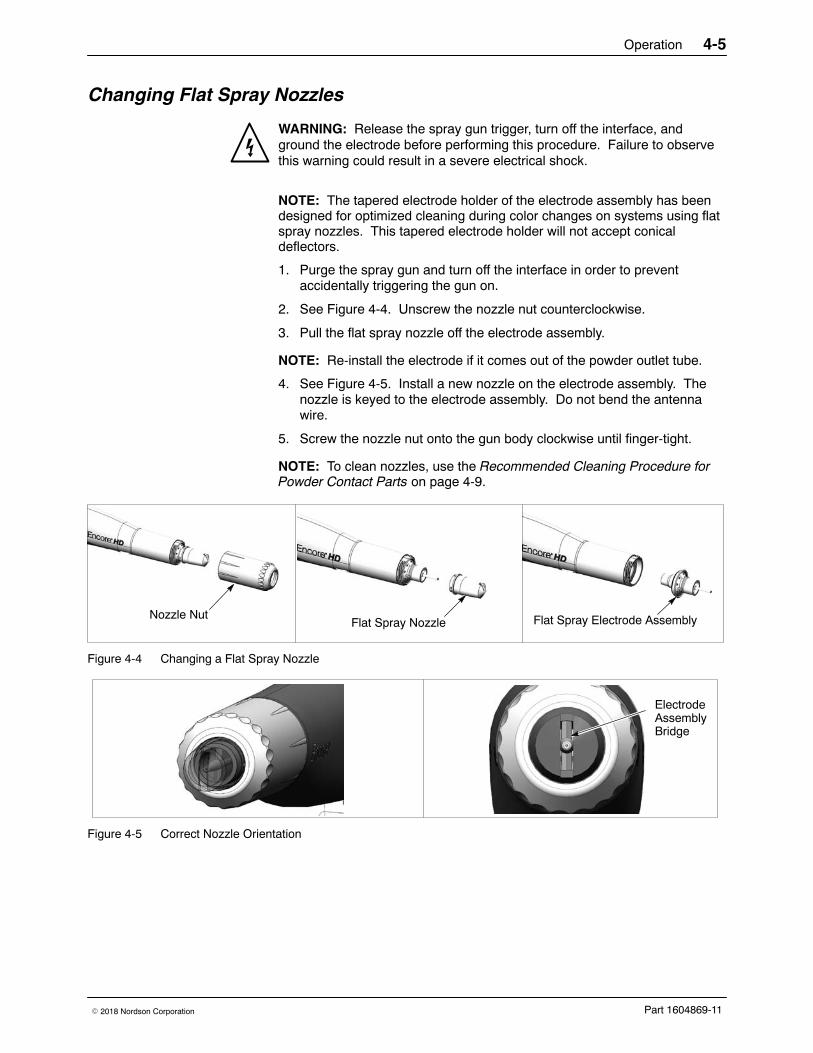
2. See Figure 4-4. Unscrew the nozzle nut counterclockwise.
3. Pull the flat spray nozzle off the electrode assembly.
NOTE: Re-install the electrode if it comes out of the powder outlet tube.
4. See Figure 4-5. Install a new nozzle on the electrode assembly. Thenozzle is keyed to the electrode assembly. Do not bend the antennawire.
5. Screw the nozzle nut onto the gun body clockwise until finger-tight.
NOTE: To clean nozzles, use the Recommended Cleaning Procedure forPowder Contact Parts on page 4-9.
Flat Spray Nozzle Flat Spray Electrode AssemblyNozzle Nut
Figure 4-4 Changing a Flat Spray Nozzle
ElectrodeAssemblyBridge
Figure 4-5 Correct Nozzle Orientation
Operation4-6
Part 1604869-11 � 2018 Nordson Corporation
Converting from Flat Spray Nozzles to Conical Nozzles
WARNING: Release the spray gun trigger, turn off the interface, andground the electrode before performing this procedure. Failure to observethis warning could result in a severe electrical shock.
NOTE: The tapered flat spray electrode holder shipped with the gun willneed to be changed in order to accept the conical nozzles and deflectors.The conical nozzle kit shipped with the gun is required for this conversion.
1. Purge the spray gun and turn off the interface in order to preventaccidentally triggering the gun on.
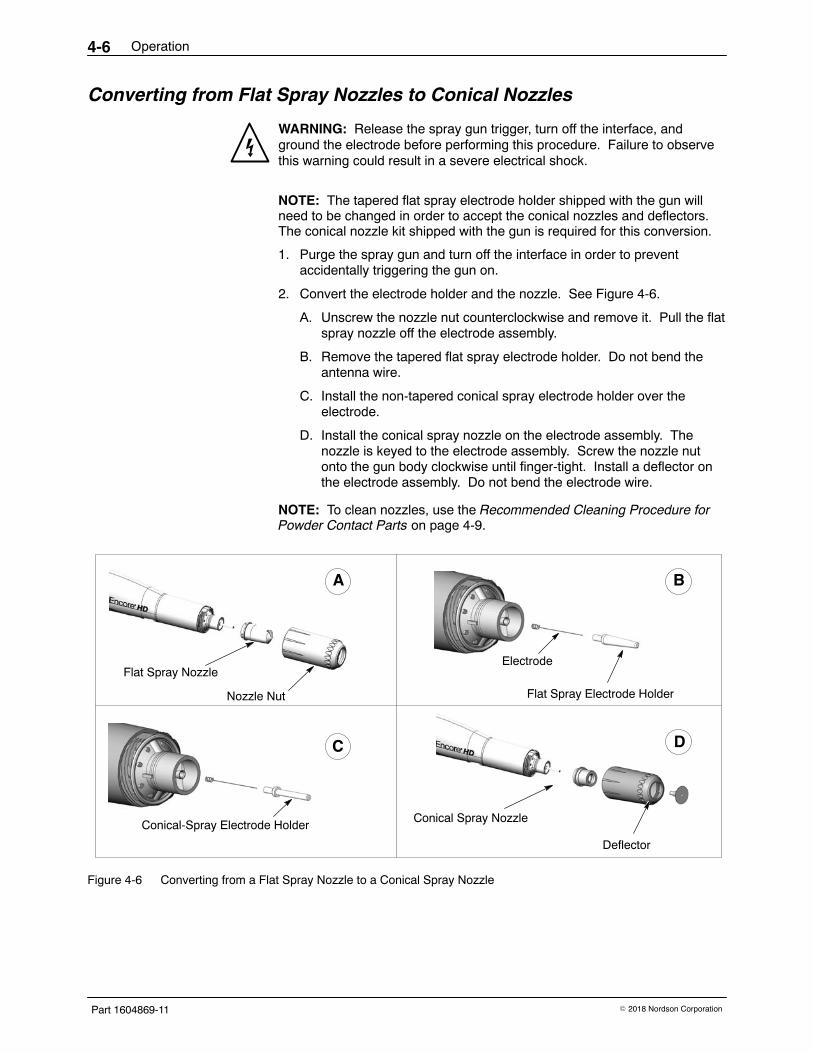
2. Convert the electrode holder and the nozzle. See Figure 4-6.
A. Unscrew the nozzle nut counterclockwise and remove it. Pull the flatspray nozzle off the electrode assembly.
B. Remove the tapered flat spray electrode holder. Do not bend theantenna wire.
C. Install the non-tapered conical spray electrode holder over theelectrode.
D. Install the conical spray nozzle on the electrode assembly. Thenozzle is keyed to the electrode assembly. Screw the nozzle nutonto the gun body clockwise until finger-tight. Install a deflector onthe electrode assembly. Do not bend the electrode wire.
NOTE: To clean nozzles, use the Recommended Cleaning Procedure forPowder Contact Parts on page 4-9.
Nozzle Nut
Flat Spray Nozzle
Flat Spray Electrode Holder
Electrode
Conical-Spray Electrode HolderConical Spray Nozzle
Deflector
A
DC
B
Figure 4-6 Converting from a Flat Spray Nozzle to a Conical Spray Nozzle
Operation 4-7
Part 1604869-11� 2018 Nordson Corporation
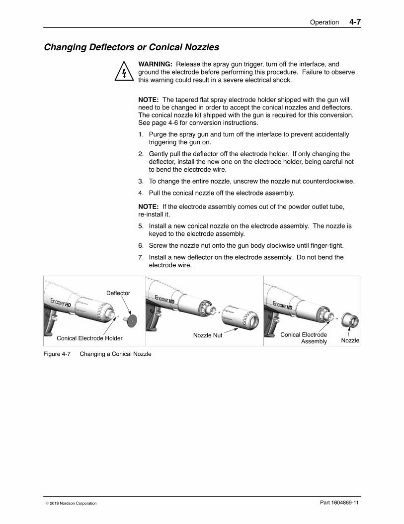
Changing Deflectors or Conical Nozzles
WARNING: Release the spray gun trigger, turn off the interface, andground the electrode before performing this procedure. Failure to observethis warning could result in a severe electrical shock.
NOTE: The tapered flat spray electrode holder shipped with the gun willneed to be changed in order to accept the conical nozzles and deflectors.The conical nozzle kit shipped with the gun is required for this conversion.See page 4-6 for conversion instructions.
1. Purge the spray gun and turn off the interface to prevent accidentallytriggering the gun on.
2. Gently pull the deflector off the electrode holder. If only changing thedeflector, install the new one on the electrode holder, being careful notto bend the electrode wire.
3. To change the entire nozzle, unscrew the nozzle nut counterclockwise.
4. Pull the conical nozzle off the electrode assembly.
NOTE: If the electrode assembly comes out of the powder outlet tube,re-install it.
5. Install a new conical nozzle on the electrode assembly. The nozzle iskeyed to the electrode assembly.
6. Screw the nozzle nut onto the gun body clockwise until finger-tight.
7. Install a new deflector on the electrode assembly. Do not bend theelectrode wire.
Deflector
Nozzle NutNozzleConical Electrode Holder
Conical ElectrodeAssembly
Figure 4-7 Changing a Conical Nozzle
Operation4-8
Part 1604869-11 � 2018 Nordson Corporation
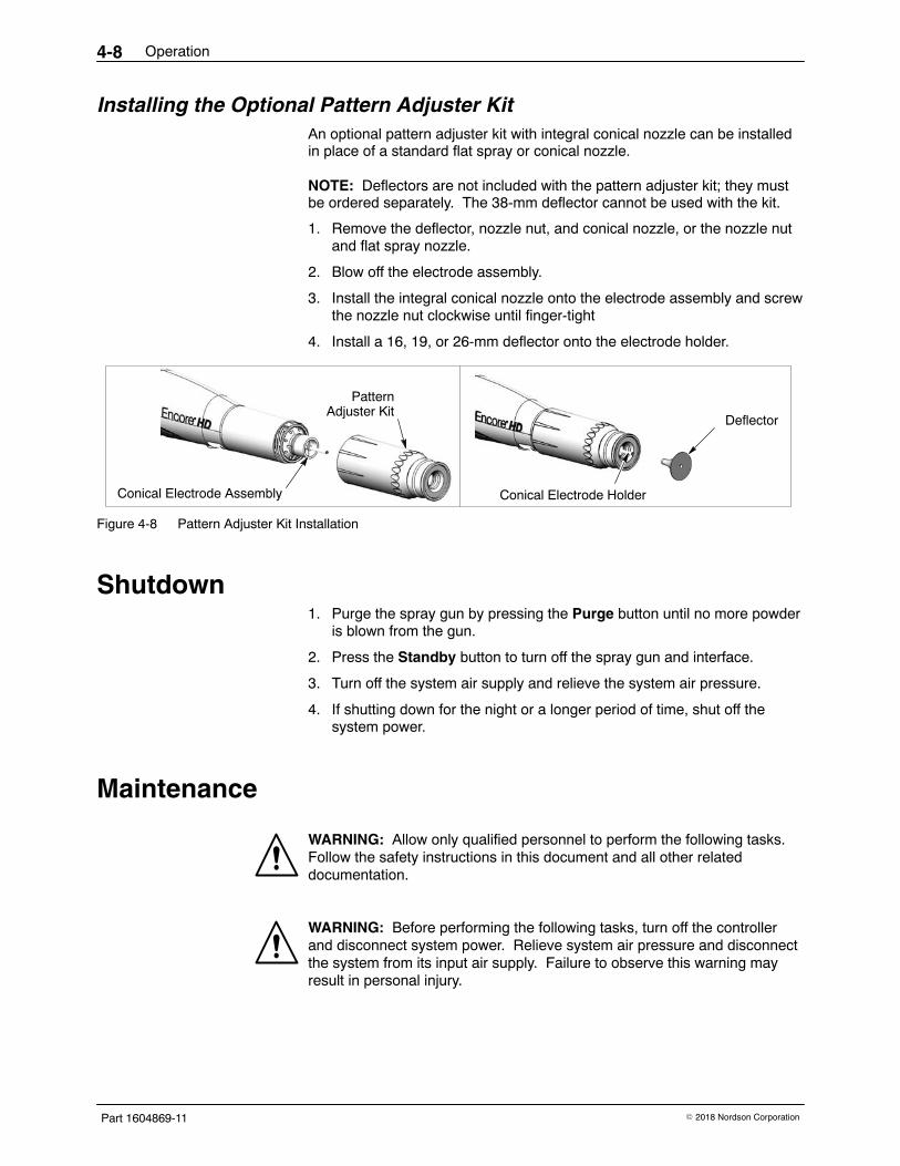
Installing the Optional Pattern Adjuster Kit An optional pattern adjuster kit with integral conical nozzle can be installedin place of a standard flat spray or conical nozzle.
NOTE: Deflectors are not included with the pattern adjuster kit; they mustbe ordered separately. The 38-mm deflector cannot be used with the kit.
1. Remove the deflector, nozzle nut, and conical nozzle, or the nozzle nutand flat spray nozzle.
2. Blow off the electrode assembly.
3. Install the integral conical nozzle onto the electrode assembly and screwthe nozzle nut clockwise until finger-tight
4. Install a 16, 19, or 26-mm deflector onto the electrode holder.
Deflector
Conical Electrode Assembly
PatternAdjuster Kit
Conical Electrode Holder
Figure 4-8 Pattern Adjuster Kit Installation
Shutdown1. Purge the spray gun by pressing the Purge button until no more powder
is blown from the gun.
2. Press the Standby button to turn off the spray gun and interface.
3. Turn off the system air supply and relieve the system air pressure.
4. If shutting down for the night or a longer period of time, shut off thesystem power.
Maintenance
WARNING: Allow only qualified personnel to perform the following tasks.Follow the safety instructions in this document and all other relateddocumentation.
WARNING: Before performing the following tasks, turn off the controllerand disconnect system power. Relieve system air pressure and disconnectthe system from its input air supply. Failure to observe this warning mayresult in personal injury.

Operation 4-9
Part 1604869-11� 2018 Nordson Corporation
Recommended Cleaning Procedure for Powder Contact Parts Nordson Corporation recommends using an ultrasonic cleaning machineand Oakite� BetaSolv emulsion cleaner to clean spray gun nozzles andpowder path parts.
NOTE: Do not immerse the electrode assembly in solvent. It cannot bedisassembled; cleaning solution and rinse water will remain inside theassembly.
1. Fill an ultrasonic cleaner with BetaSolv or an equivalent emulsioncleaning solution at room temperature. Do not heat the cleaningsolution.
2. Remove the parts to be cleaned from the gun. Remove the O-rings.Blow off the parts with low-pressure compressed air.
NOTE: Do not allow the O-rings to come in contact with the cleaningsolution.
3. Place the parts in the ultrasonic cleaner and run the cleaner until allparts are clean and free of impact fusion.
4. Rinse all parts in clean water and dry before re-assembling the spraygun. Inspect the O-rings and replace any that are damaged.
NOTE: Do not use sharp or hard tools that will scratch or gouge the smoothsurfaces of powder contact parts. Scratches will cause impact fusion.
Maintenance Procedures
Component Procedure
Spray Gun(Daily)
1. Point the spray gun into the booth. Remove the suction line from the hopper or boxfeeder and point them in the booth, as well. Push the Color Change button on thesystem controller and purge the powder delivery system.
2. Remove the nozzle and electrode assembly and clean them with low pressurecompressed air and clean cloths. Check them for wear, and replace them ifnecessary.
3. Clean the gun face surface (where the electrode assembly attaches) with lowpressure compressed air and a clean cloth.
4. Blow off the gun and wipe it down with a clean cloth.
SystemGrounds
Daily: Make sure the system is securely connected to a true earth ground beforespraying powder.
Periodically: Check all system ground connections.

Operation4-10
Part 1604869-11 � 2018 Nordson Corporation
Repair 5-1
Part 1604869-11� 2018 Nordson Corporation
Section 5Repair
WARNING: Allow only qualified personnel to perform the following tasks.Follow the safety instructions in this document and all other relateddocumentation.
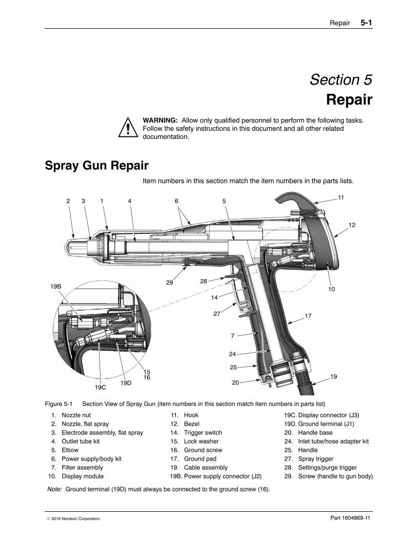
Spray Gun Repair Item numbers in this section match the item numbers in the parts lists.
2 3 1 64 5
7
14
28
19
10
12
11
20
27
24
25
17
2919B
19C19D
1516
Figure 5-1 Section View of Spray Gun (item numbers in this section match item numbers in parts list)
1. Nozzle nut2. Nozzle, flat spray3. Electrode assembly, flat spray4. Outlet tube kit5. Elbow6. Power supply/body kit7. Filter assembly
10. Display module
11. Hook12. Bezel14. Trigger switch15. Lock washer16. Ground screw17. Ground pad19. Cable assembly19B. Power supply connector (J2)
19C. Display connector (J3)19D. Ground terminal (J1)20. Handle base24. Inlet tube/hose adapter kit25. Handle27. Spray trigger28. Settings/purge trigger29. Screw (handle to gun body)
Note: Ground terminal (19D) must always be connected to the ground screw (16).
Repair5-2
Part 1604869-11 � 2018 Nordson Corporation
Display Module Replacement
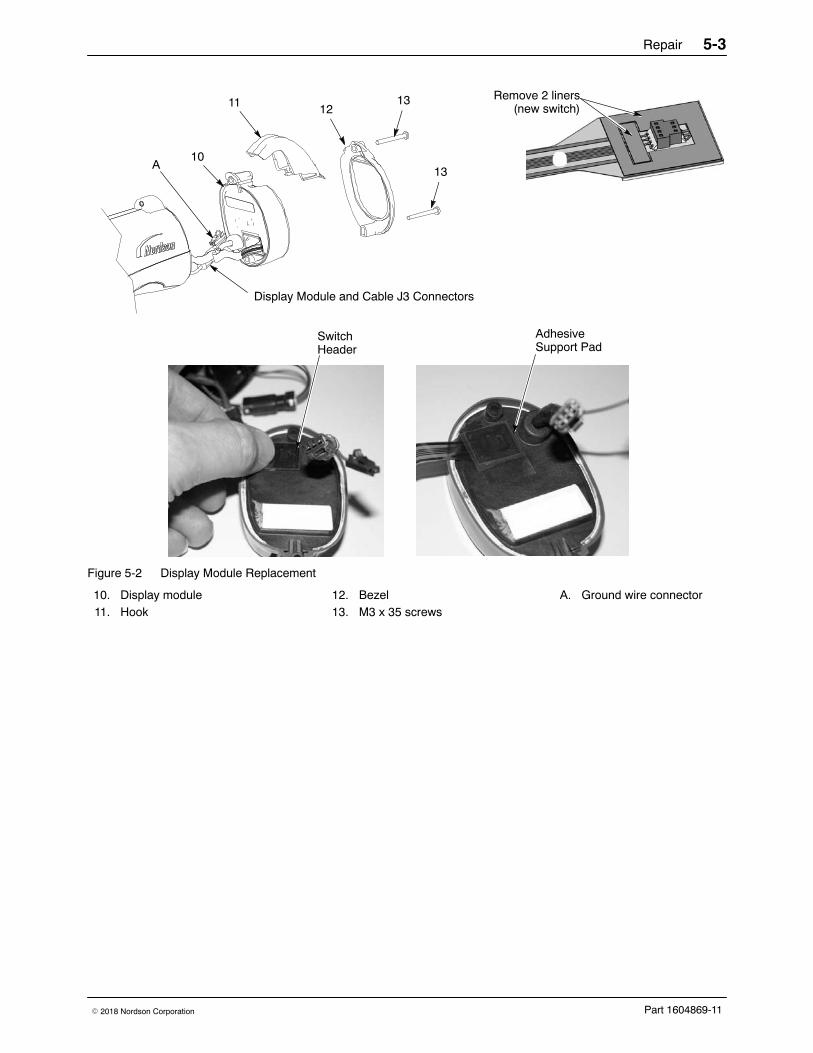
Display Module Removal 1. See Figures 5-1 and 5-2. Unscrew the top and bottom screws (13)
holding the bezel (12), hook (11) and display module (10) onto the gunbody.
2. Remove the bezel and slide the hook off the display module.
3. Carefully pull the display module away from the gun.
4. Insert a small screwdriver into the recess in the J3 gun cable/displaymodule connectors to release the catch and disconnect them.
5. Carefully remove the adhesive support pad and the trigger switchheader from the display module.
6. If the adhesive support pad remains stuck to the trigger switch header,carefully peel the pad off. Both the display module kit and trigger switchkit include new adhesive support pads.
Display Module Installation 1. On the display module (10), carefully clean the trigger switch header
mounting surface and surrounding area with isopropyl alcohol. Allowthe surface to dry completely before proceeding.
2. If you are installing a new trigger switch, remove the two liners from theconnector side of the trigger switch header as shown in Figure 5-2.
3. Align the trigger switch header with the display module receptacle andpush on the header to connect it. Apply even pressure on the header toseal it tightly against the display module.
4. Remove the liner from the new adhesive support pad and install it overthe trigger switch header. Apply even pressure on the support pad toseal it to the display module.
5. Connect the J3 display module and cable connector together. Theground wire connector (A) is not used for this version of the gun.
6. Gently fold the trigger switch ribbon cable and display module cable intothe gun, and install the display module onto the gun.
7. Slide the hook (11) onto the display module, then install the bezel (12).
8. Install and tighten the screws (13).
Repair 5-3
Part 1604869-11� 2018 Nordson Corporation
12
1310
11
AdhesiveSupport Pad
SwitchHeader
Remove 2 liners(new switch)
13
Display Module and Cable J3 Connectors
A
Figure 5-2 Display Module Replacement
10. Display module11. Hook
12. Bezel13. M3 x 35 screws
A. Ground wire connector
Repair5-4
Part 1604869-11 � 2018 Nordson Corporation
Power Supply and Powder Path Replacement
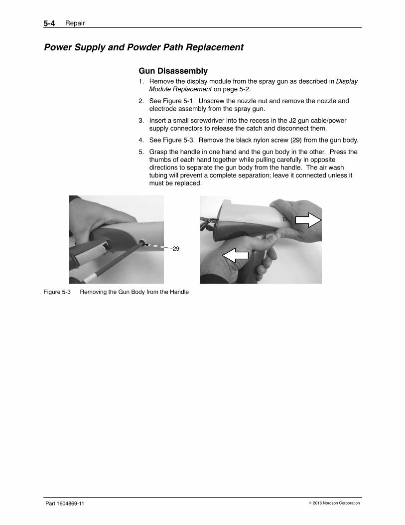
Gun Disassembly 1. Remove the display module from the spray gun as described in Display
Module Replacement on page 5-2.
2. See Figure 5-1. Unscrew the nozzle nut and remove the nozzle andelectrode assembly from the spray gun.
3. Insert a small screwdriver into the recess in the J2 gun cable/powersupply connectors to release the catch and disconnect them.
4. See Figure 5-3. Remove the black nylon screw (29) from the gun body.
5. Grasp the handle in one hand and the gun body in the other. Press thethumbs of each hand together while pulling carefully in oppositedirections to separate the gun body from the handle. The air washtubing will prevent a complete separation; leave it connected unless itmust be replaced.
29
Figure 5-3 Removing the Gun Body from the Handle
Repair 5-5
Part 1604869-11� 2018 Nordson Corporation
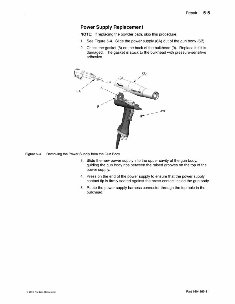
Power Supply Replacement NOTE: If replacing the powder path, skip this procedure.
1. See Figure 5-4. Slide the power supply (6A) out of the gun body (6B).
2. Check the gasket (8) on the back of the bulkhead (9). Replace it if it isdamaged. The gasket is stuck to the bulkhead with pressure-sensitiveadhesive.
6A
299
8
6B
Figure 5-4 Removing the Power Supply from the Gun Body
3. Slide the new power supply into the upper cavity of the gun body,guiding the gun body ribs between the raised grooves on the top of thepower supply.
4. Press on the end of the power supply to ensure that the power supplycontact tip is firmly seated against the brass contact inside the gun body.
5. Route the power supply harness connector through the top hole in thebulkhead.
Repair5-6
Part 1604869-11 � 2018 Nordson Corporation
Powder Path Removal NOTE: Skip these steps if not replacing the powder path. Go to page 5-8to reassemble the spray gun.
1. Perform the Gun Disassembly procedure on page 5-4.
2. See Figure 5-5. Remove the elbow (5) from the inlet tube (24).
3. Remove the two M3 x 20 screws (21) from the handle base (20).
4. Pull the base away from the handle, then swing the bottom of theground pad (17) up and away from the handle, then remove it. Leavethe ground wire connected to the ground pad.
5. Push the inlet tube (24) up and out of the base, then move the base outof the way and pull the inlet tube out of the handle.
6. Push the outlet tube (4) out of the front of the gun body (6B).
7. Blow off the inlet tube, outlet tube, and elbow, and replace them if theinteriors are worn or coated with impact-fused powder. If re-using thetubes, make sure the O-rings are undamaged.
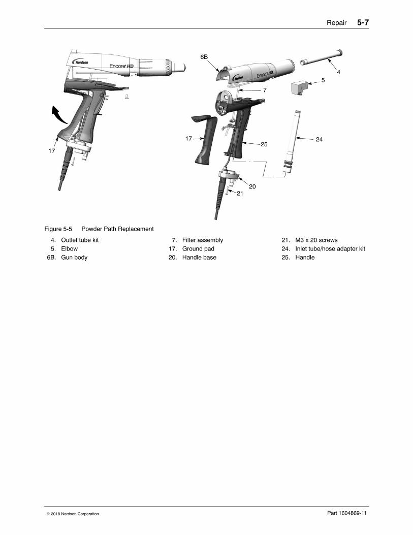
Powder Path Installation 1. See Figure 5-5. Install the outlet tube (4) into the gun body (6B), with
the end of the tube flush with the end of the gun body.
2. Install the inlet tube (24) into the handle (25), then install the end of thetube into the handle base (20).
3. Push the handle base close to the handle, then hook the top end of theground pad (17) into the body and rotate it onto the handle. Make surethe cable wires are not pinched or trapped during re-assembly.
4. Install the handle base onto the handle and ground pad and secure itwith the two M3 x 20 screws (21).
5. Install the elbow (5) onto the inlet tube, with the end oriented toward thefront of the gun as shown.
NOTE: To verify proper installation, place a flashlight inside the bottom ofthe inlet adapter and verify the internal connections by looking through theoutlet tube from the front of the powder spray gun.
Repair 5-7
Part 1604869-11� 2018 Nordson Corporation
17
7
24
6B
4
2120
5
2517
Figure 5-5 Powder Path Replacement
4. Outlet tube kit5. Elbow
6B. Gun body
7. Filter assembly17. Ground pad20. Handle base
21. M3 x 20 screws24. Inlet tube/hose adapter kit25. Handle
Repair5-8
Part 1604869-11 � 2018 Nordson Corporation
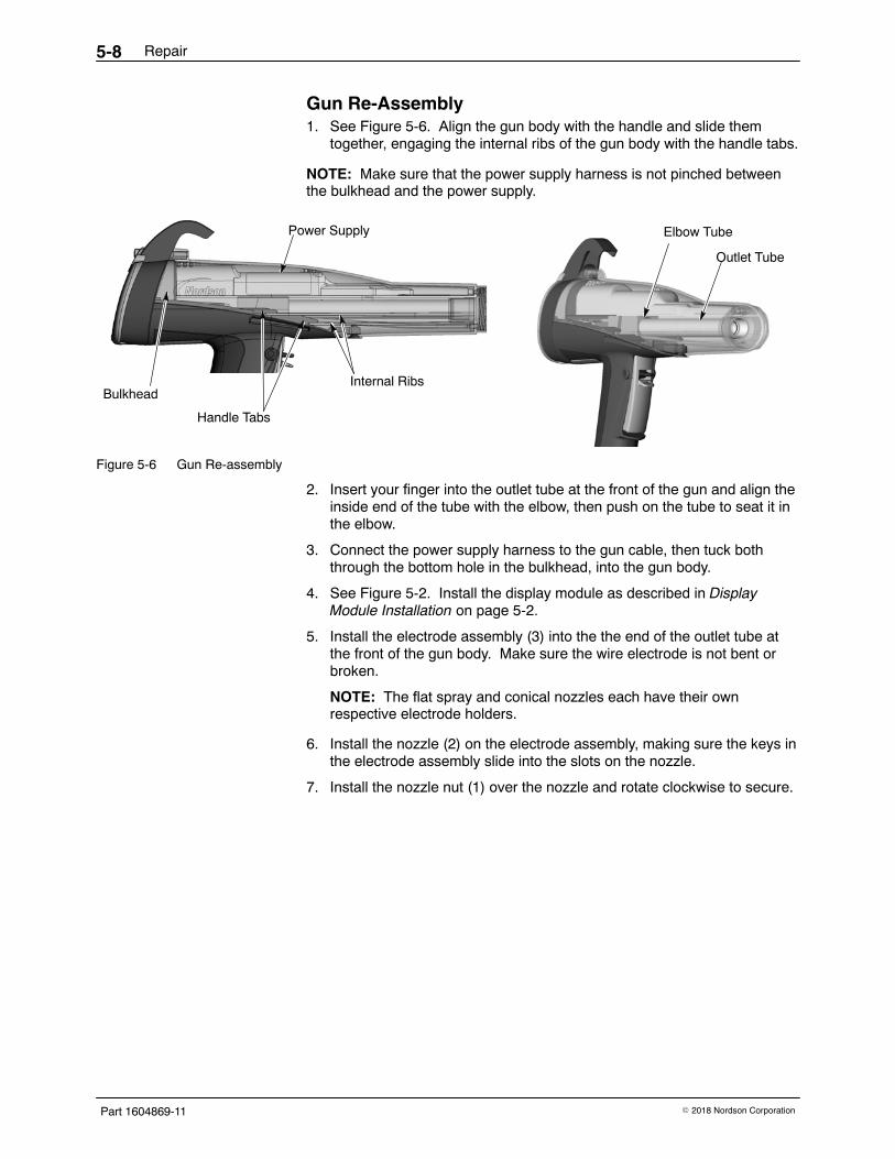
Gun Re-Assembly 1. See Figure 5-6. Align the gun body with the handle and slide them
together, engaging the internal ribs of the gun body with the handle tabs.
NOTE: Make sure that the power supply harness is not pinched betweenthe bulkhead and the power supply.
Internal Ribs
Handle Tabs
Outlet Tube
Elbow TubePower Supply
Bulkhead
Figure 5-6 Gun Re-assembly
2. Insert your finger into the outlet tube at the front of the gun and align theinside end of the tube with the elbow, then push on the tube to seat it inthe elbow.
3. Connect the power supply harness to the gun cable, then tuck boththrough the bottom hole in the bulkhead, into the gun body.
4. See Figure 5-2. Install the display module as described in DisplayModule Installation on page 5-2.
5. Install the electrode assembly (3) into the the end of the outlet tube atthe front of the gun body. Make sure the wire electrode is not bent orbroken.
NOTE: The flat spray and conical nozzles each have their ownrespective electrode holders.
6. Install the nozzle (2) on the electrode assembly, making sure the keys inthe electrode assembly slide into the slots on the nozzle.
7. Install the nozzle nut (1) over the nozzle and rotate clockwise to secure.
Repair 5-9
Part 1604869-11� 2018 Nordson Corporation
Cable Replacement
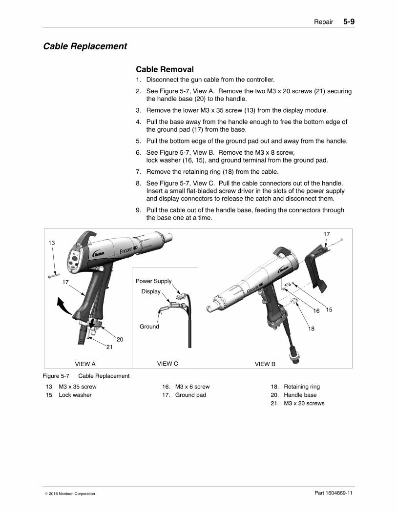
Cable Removal 1. Disconnect the gun cable from the controller.
2. See Figure 5-7, View A. Remove the two M3 x 20 screws (21) securingthe handle base (20) to the handle.
3. Remove the lower M3 x 35 screw (13) from the display module.
4. Pull the base away from the handle enough to free the bottom edge ofthe ground pad (17) from the base.
5. Pull the bottom edge of the ground pad out and away from the handle.
6. See Figure 5-7, View B. Remove the M3 x 8 screw,lock washer (16, 15), and ground terminal from the ground pad.
7. Remove the retaining ring (18) from the cable.
8. See Figure 5-7, View C. Pull the cable connectors out of the handle.Insert a small flat-bladed screw driver in the slots of the power supplyand display connectors to release the catch and disconnect them.
9. Pull the cable out of the handle base, feeding the connectors throughthe base one at a time.
17
2120
18
16
17
VIEW A VIEW BVIEW C
Power Supply
Ground
Display
13
15
Figure 5-7 Cable Replacement
13. M3 x 35 screw15. Lock washer
16. M3 x 6 screw17. Ground pad
18. Retaining ring20. Handle base21. M3 x 20 screws
Repair5-10
Part 1604869-11 � 2018 Nordson Corporation
Cable Installation 1. See Figure 5-7. Feed a new cable through the handle base, then install
the retaining ring (18) on the cable to hold it in place.
2. Connect the cable to the display module and power supply connectors.
3. Connect the cable terminal to the ground pad (17) with the M3 x 6 screwand lock washer (16, 15).
4. Tuck the cable connectors and ground wire into the gun, below themultiplier.
5. Hook the top of the ground pad into the gun body, then rotate it intoposition on the handle.
6. Push the handle base (20) up against the handle and ground pad, andtighten securely the two M3 x 20 screws (21) in the base.
7. Re-install the M3 x 35 screw (13) in the bottom of the display module.
Trigger Switch Replacement
Switch Removal 1. Remove the display module and disconnect the trigger switch ribbon
cable from the module as described in Display Module Removal onpage 5-2.
2. Remove the gun body from the handle as described in GunDisassembly on page 5-4.
3. See Figure 6-8. Pull out the elbow (5) off the inlet tube.
4. Push the small diameter end of the axle (30) out of the handle with asmall, flat-ended punch or other tool.
5. Remove the spray trigger (27), actuator (26), and purge trigger (28) fromthe handle.
6. Use a tool to pry and pull the trigger switch (14) off the handle, then pullit up and out of the handle.
Repair 5-11
Part 1604869-11� 2018 Nordson Corporation
528
27
2630
14
Gusset
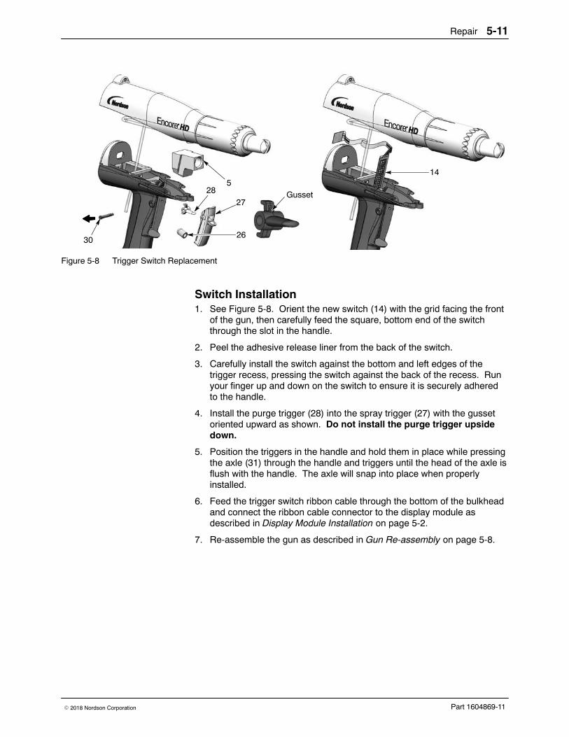
Figure 5-8 Trigger Switch Replacement
Switch Installation 1. See Figure 5-8. Orient the new switch (14) with the grid facing the front
of the gun, then carefully feed the square, bottom end of the switchthrough the slot in the handle.
2. Peel the adhesive release liner from the back of the switch.
3. Carefully install the switch against the bottom and left edges of thetrigger recess, pressing the switch against the back of the recess. Runyour finger up and down on the switch to ensure it is securely adheredto the handle.
4. Install the purge trigger (28) into the spray trigger (27) with the gussetoriented upward as shown. Do not install the purge trigger upsidedown.
5. Position the triggers in the handle and hold them in place while pressingthe axle (31) through the handle and triggers until the head of the axle isflush with the handle. The axle will snap into place when properlyinstalled.
6. Feed the trigger switch ribbon cable through the bottom of the bulkheadand connect the ribbon cable connector to the display module asdescribed in Display Module Installation on page 5-2.
7. Re-assemble the gun as described in Gun Re-assembly on page 5-8.

Repair5-12
Part 1604869-11 � 2018 Nordson Corporation
Troubleshooting 6-1
Part 1604869-11� 2018 Nordson Corporation
Section 6Troubleshooting
WARNING: Allow only qualified personnel to perform the following tasks.Follow the safety instructions in this document and all other relateddocumentation.
WARNING: Before making repairs to the controller or spray gun, shut offsystem power and disconnect the power cord. Shut off the compressed airsupply to the system and relieve the system pressure. Failure to observethis warning could result in personal injury.
These troubleshooting procedures cover only the most common problems.If you cannot solve a problem with the information given here, contactNordson technical support at (800) 433−9319 or your local Nordsonrepresentative for help.
Troubleshooting6-2
Part 1604869-11 � 2018 Nordson Corporation
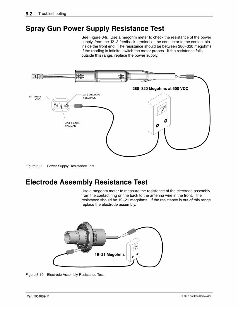
Spray Gun Power Supply Resistance Test See Figure 6-9. Use a megohm meter to check the resistance of the powersupply, from the J2−3 feedback terminal at the connector to the contact pininside the front end. The resistance should be between 280−320 megohms.If the reading is infinite, switch the meter probes. If the resistance fallsoutside this range, replace the power supply.
J2−3 (YELLOW)FEEDBACK
J2−2 (BLACK)COMMON
J2−1 (RED)OSC
280−320 Megohms at 500 VDC
Figure 6-9 Power Supply Resistance Test
Electrode Assembly Resistance Test Use a megohm meter to measure the resistance of the electrode assemblyfrom the contact ring on the back to the antenna wire in the front. Theresistance should be 19−21 megohms. If the resistance is out of this rangereplace the electrode assembly.
19−21 Megohms
Figure 6-10 Electrode Assembly Resistance Test
Troubleshooting 6-3
Part 1604869-11� 2018 Nordson Corporation
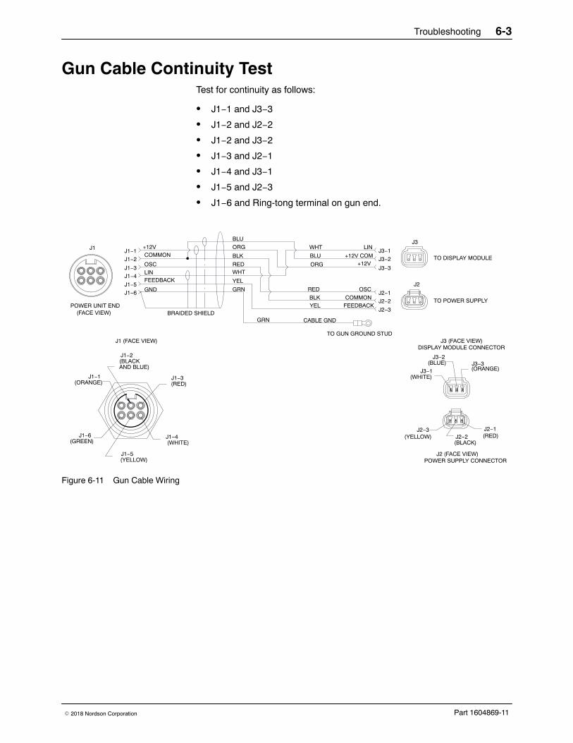
Gun Cable Continuity Test Test for continuity as follows:
� J1−1 and J3−3
� J1−2 and J2−2
� J1−2 and J3−2
� J1−3 and J2−1
� J1−4 and J3−1
� J1−5 and J2−3
� J1−6 and Ring-tong terminal on gun end.
+12V LINCOMMON
OSC
OSC
LIN
COMMON
+12V COMJ1−1
J1−2
J1−3
J1−4
J1−5
J1−6
FEEDBACK
GND
BRAIDED SHIELD
GRN
WHT
CABLE GNDGRN
BLK
RED
J2−2
J2−1
RED
BLK
ORG
BLU
WHTJ3−1
J3−2
YEL
J3−3+12VORG
J2−3FEEDBACKYEL
BLU
J1−1(ORANGE)
J1−3(RED)
J1−6(GREEN)
J1−5(YELLOW)
J1−4(WHITE)
J1 (FACE VIEW)
J1−2(BLACKAND BLUE)
J1
POWER UNIT END(FACE VIEW)
J3
J3 (FACE VIEW)DISPLAY MODULE CONNECTOR
J3−1(WHITE)
J3−2(BLUE) J3−3
(ORANGE)
J2 (FACE VIEW)POWER SUPPLY CONNECTOR
J2−3(YELLOW)
J2−1(RED)J2−2
(BLACK)
J2
TO DISPLAY MODULE
TO POWER SUPPLY
TO GUN GROUND STUD
Figure 6-11 Gun Cable Wiring

Troubleshooting6-4
Part 1604869-11 � 2018 Nordson Corporation
Parts 7-1
Part 1604869-11� 2018 Nordson Corporation
Section 7Parts
Introduction To order parts, call the Nordson Industrial Coating Systems CustomerSupport Center at (800) 433-9319 or contact your local Nordsonrepresentative.
This section covers parts and options for the Encore HD manual powderspray gun.
Refer to the following manuals for additional information and optionalequipment.
1604870 Encore HD/XT System Controller Manual1604971 Lance Extensions for Encore HD Manual Powder Spray Guns1100013 Pattern Adjuster Kit for Lance Extensions1098440 Pattern Adjuster Kit for Encore Manual Spray Guns1102764 Encore Cup Gun Kit
These manuals can be downloaded from:http://emanuals.nordson.com/finishing/(click on Powder−US, then Encore Systems)
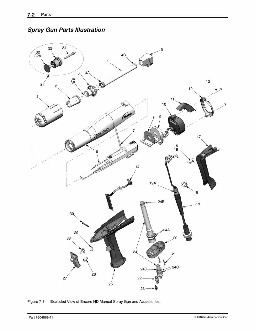
Spray Gun Parts See Figure 7-1 and the parts list on the following pages.
Parts7-2
Part 1604869-11 � 2018 Nordson Corporation
Spray Gun Parts Illustration
1
2
4
5
6
8 9
1011
12
13
7
17
18
19
20
21
15
14
29
24
28
2227
2325
16
4A
4B
24B
24A
3332
32A
30
26
19A
3
34
31
3A3B
24C24D
Figure 7-1 Exploded View of Encore HD Manual Spray Gun and Accessories
Parts 7-3
Part 1604869-11� 2018 Nordson Corporation
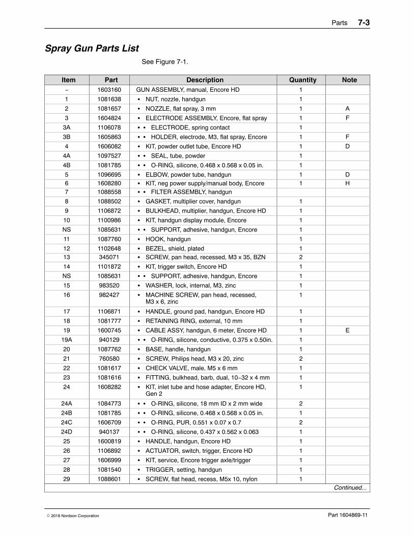
Spray Gun Parts List See Figure 7-1.
Item Part Description Quantity Note− 1603160 GUN ASSEMBLY, manual, Encore HD 1
1 1081638 � NUT, nozzle, handgun 1
2 1081657 � NOZZLE, flat spray, 3 mm 1 A
3 1604824 � ELECTRODE ASSEMBLY, Encore, flat spray 1 F
3A 1106078 � � ELECTRODE, spring contact 1
3B 1605863 � � HOLDER, electrode, M3, flat spray, Encore 1 F
4 1606082 � KIT, powder outlet tube, Encore HD 1 D
4A 1097527 � � SEAL, tube, powder 1
4B 1081785 � � O-RING, silicone, 0.468 x 0.568 x 0.05 in. 1
5 1096695 � ELBOW, powder tube, handgun 1 D6 1608280 � KIT, neg power supply/manual body, Encore 1 H7 1088558 � � FILTER ASSEMBLY, handgun
8 1088502 � GASKET, multiplier cover, handgun 1
9 1106872 � BULKHEAD, multiplier, handgun, Encore HD 1
10 1100986 � KIT, handgun display module, Encore 1
NS 1085631 � � SUPPORT, adhesive, handgun, Encore 1
11 1087760 � HOOK, handgun 1
12 1102648 � BEZEL, shield, plated 113 345071 � SCREW, pan head, recessed, M3 x 35, BZN 2
14 1101872 � KIT, trigger switch, Encore HD 1
NS 1085631 � � SUPPORT, adhesive, handgun, Encore 1
15 983520 � WASHER, lock, internal, M3, zinc 1
16 982427 � MACHINE SCREW, pan head, recessed,M3 x 6, zinc
1
17 1106871 � HANDLE, ground pad, handgun, Encore HD 1
18 1081777 � RETAINING RING, external, 10 mm 1
19 1600745 � CABLE ASSY, handgun, 6 meter, Encore HD 1 E
19A 940129 � � O-RING, silicone, conductive, 0.375 x 0.50in. 1
20 1087762 � BASE, handle, handgun 1
21 760580 � SCREW, Philips head, M3 x 20, zinc 2
22 1081617 � CHECK VALVE, male, M5 x 6 mm 1
23 1081616 � FITTING, bulkhead, barb, dual, 10−32 x 4 mm 1
24 1608282 � KIT, inlet tube and hose adapter, Encore HD,Gen 2
1
24A 1084773 � � O-RING, silicone, 18 mm ID x 2 mm wide 2
24B 1081785 � � O-RING, silicone, 0.468 x 0.568 x 0.05 in. 1
24C 1606709 � � O-RING, PUR, 0.551 x 0.07 x 0.7 2
24D 940137 � � O-RING, silicone, 0.437 x 0.562 x 0.063 1
25 1600819 � HANDLE, handgun, Encore HD 1
26 1106892 � ACTUATOR, switch, trigger, Encore HD 1
27 1606999 � KIT, service, Encore trigger axle/trigger 1
28 1081540 � TRIGGER, setting, handgun 1
29 1088601 � SCREW, flat head, recess, M5x 10, nylon 1Continued...
Parts7-4
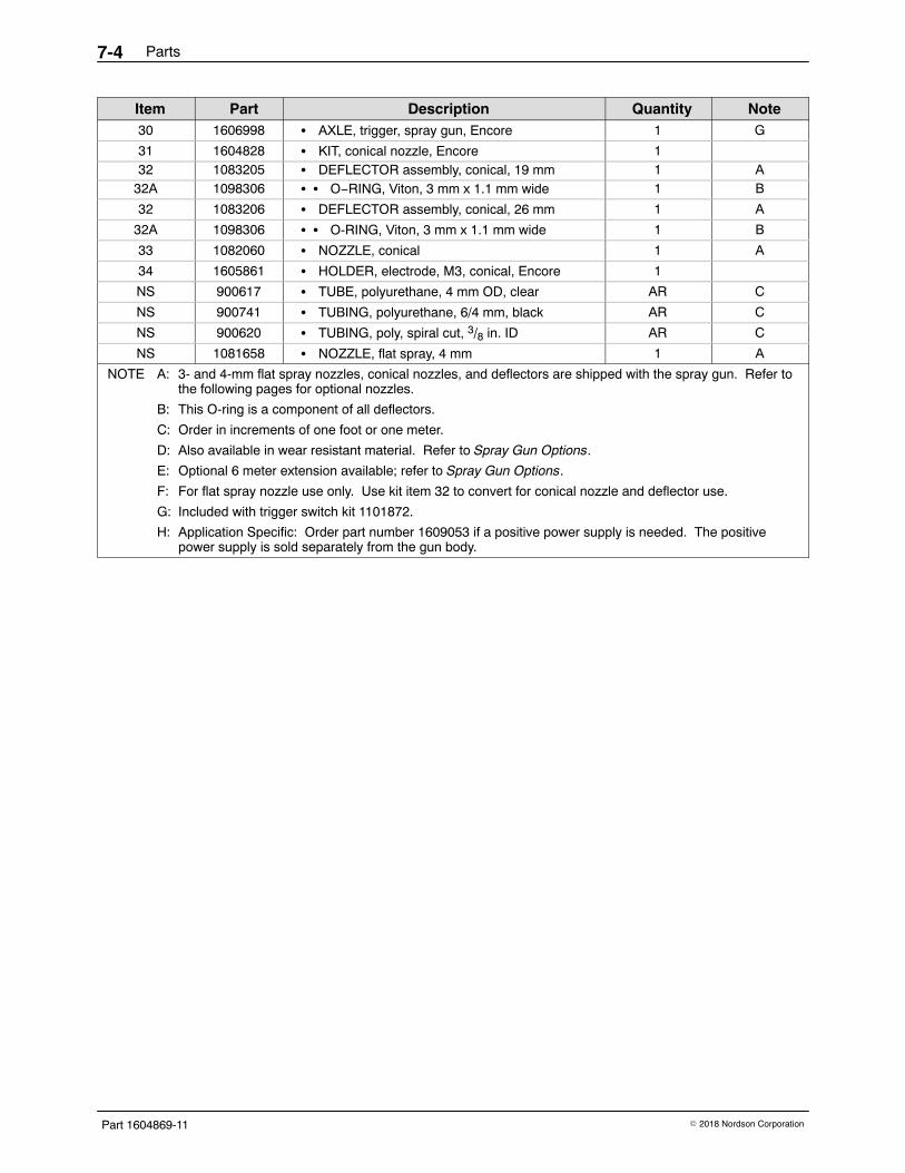
Part 1604869-11 � 2018 Nordson Corporation
NoteQuantityDescriptionPartItem30 1606998 � AXLE, trigger, spray gun, Encore 1 G
31 1604828 � KIT, conical nozzle, Encore 132 1083205 � DEFLECTOR assembly, conical, 19 mm 1 A
32A 1098306 � � O−RING, Viton, 3 mm x 1.1 mm wide 1 B
32 1083206 � DEFLECTOR assembly, conical, 26 mm 1 A
32A 1098306 � � O-RING, Viton, 3 mm x 1.1 mm wide 1 B
33 1082060 � NOZZLE, conical 1 A
34 1605861 � HOLDER, electrode, M3, conical, Encore 1
NS 900617 � TUBE, polyurethane, 4 mm OD, clear AR C
NS 900741 � TUBING, polyurethane, 6/4 mm, black AR C
NS 900620 � TUBING, poly, spiral cut, 3/8 in. ID AR C
NS 1081658 � NOZZLE, flat spray, 4 mm 1 A
NOTE A: 3- and 4-mm flat spray nozzles, conical nozzles, and deflectors are shipped with the spray gun. Refer tothe following pages for optional nozzles.
B: This O-ring is a component of all deflectors.
C: Order in increments of one foot or one meter.
D: Also available in wear resistant material. Refer to Spray Gun Options.
E: Optional 6 meter extension available; refer to Spray Gun Options.
F: For flat spray nozzle use only. Use kit item 32 to convert for conical nozzle and deflector use.
G: Included with trigger switch kit 1101872.
H: Application Specific: Order part number 1609053 if a positive power supply is needed. The positivepower supply is sold separately from the gun body.
Parts 7-5
Part 1604869-11� 2018 Nordson Corporation
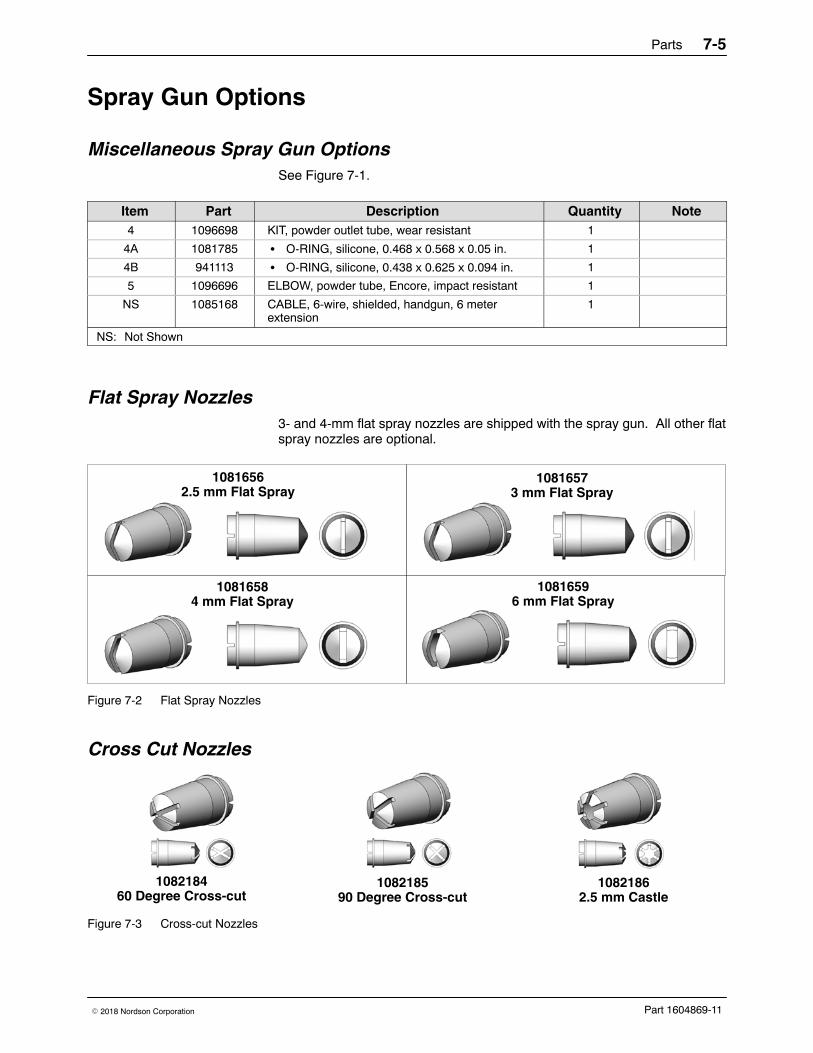
Spray Gun Options
Miscellaneous Spray Gun Options See Figure 7-1.
Item Part Description Quantity Note4 1096698 KIT, powder outlet tube, wear resistant 1
4A 1081785 � O-RING, silicone, 0.468 x 0.568 x 0.05 in. 1
4B 941113 � O-RING, silicone, 0.438 x 0.625 x 0.094 in. 1
5 1096696 ELBOW, powder tube, Encore, impact resistant 1
NS 1085168 CABLE, 6-wire, shielded, handgun, 6 meterextension
1
NS: Not Shown
Flat Spray Nozzles 3- and 4-mm flat spray nozzles are shipped with the spray gun. All other flatspray nozzles are optional.
10816562.5 mm Flat Spray
10816573 mm Flat Spray
10816584 mm Flat Spray
10816596 mm Flat Spray
Figure 7-2 Flat Spray Nozzles
Cross Cut Nozzles
108218460 Degree Cross-cut
108218590 Degree Cross-cut
10821862.5 mm Castle
Figure 7-3 Cross-cut Nozzles
Parts7-6
Part 1604869-11 � 2018 Nordson Corporation
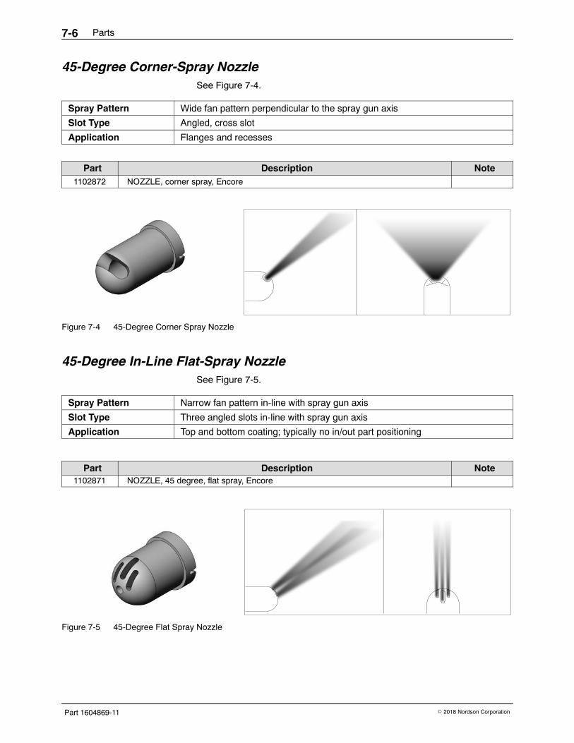
45-Degree Corner-Spray NozzleSee Figure 7-4.
Spray Pattern Wide fan pattern perpendicular to the spray gun axis
Slot Type Angled, cross slot
Application Flanges and recesses
Part Description Note1102872 NOZZLE, corner spray, Encore
Figure 7-4 45-Degree Corner Spray Nozzle
45-Degree In-Line Flat-Spray Nozzle See Figure 7-5.
Spray Pattern Narrow fan pattern in-line with spray gun axis
Slot Type Three angled slots in-line with spray gun axis
Application Top and bottom coating; typically no in/out part positioning
Part Description Note1102871 NOZZLE, 45 degree, flat spray, Encore
Figure 7-5 45-Degree Flat Spray Nozzle
Parts 7-7
Part 1604869-11� 2018 Nordson Corporation
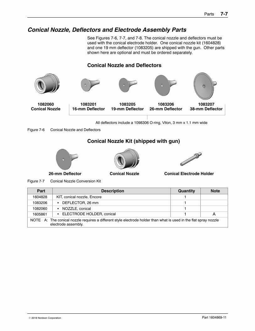
Conical Nozzle, Deflectors and Electrode Assembly PartsSee Figures 7-6, 7-7, and 7-8. The conical nozzle and deflectors must beused with the conical electrode holder. One conical nozzle kit (1604828)and one 19 mm deflector (1083205) are shipped with the gun. Other partsshown here are optional and must be ordered separately.
Conical Nozzle and Deflectors
1082060Conical Nozzle
108320116-mm Deflector
108320519-mm Deflector
108320626-mm Deflector
108320738-mm Deflector
All deflectors include a 1098306 O-ring, Viton, 3 mm x 1.1 mm wide
Figure 7-6 Conical Nozzle and Deflectors
Conical Nozzle Kit (shipped with gun)
Conical Nozzle26-mm Deflector Conical Electrode Holder
Figure 7-7 Conical Nozzle Conversion Kit
Part Description Quantity Note1604828 KIT, conical nozzle, Encore 1
1083206 � DEFLECTOR, 26 mm 1
1082060 � NOZZLE, conical 1
1605861 � ELECTRODE HOLDER, conical 1 ANOTE A: The conical nozzle requires a different style electrode holder than what is used in the flat spray nozzle
electrode assembly.
Parts7-8
Part 1604869-11 � 2018 Nordson Corporation
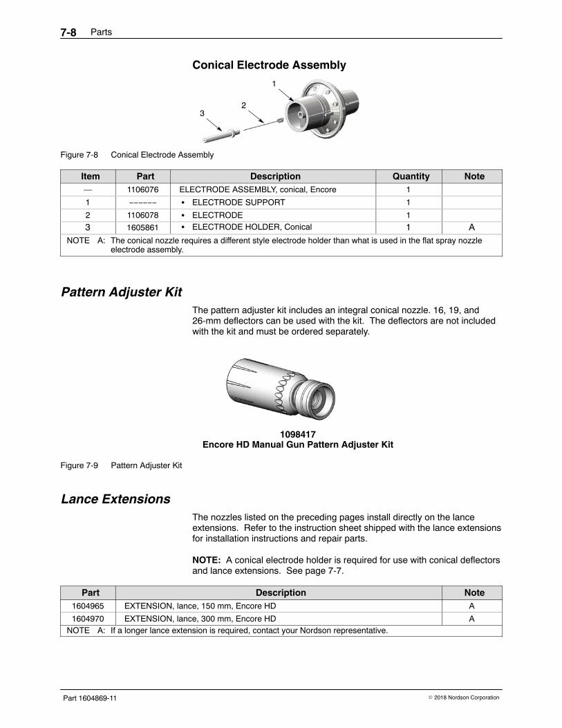
Conical Electrode Assembly
1
23
Figure 7-8 Conical Electrode Assembly
Item Part Description Quantity Note— 1106076 ELECTRODE ASSEMBLY, conical, Encore 1
1 −−−−−− � ELECTRODE SUPPORT 1
2 1106078 � ELECTRODE 1
3 1605861 � ELECTRODE HOLDER, Conical 1 ANOTE A: The conical nozzle requires a different style electrode holder than what is used in the flat spray nozzle
electrode assembly.
Pattern Adjuster Kit The pattern adjuster kit includes an integral conical nozzle. 16, 19, and26-mm deflectors can be used with the kit. The deflectors are not includedwith the kit and must be ordered separately.
1098417Encore HD Manual Gun Pattern Adjuster Kit
Figure 7-9 Pattern Adjuster Kit
Lance Extensions The nozzles listed on the preceding pages install directly on the lanceextensions. Refer to the instruction sheet shipped with the lance extensionsfor installation instructions and repair parts.
NOTE: A conical electrode holder is required for use with conical deflectorsand lance extensions. See page 7-7.
Part Description Note1604965 EXTENSION, lance, 150 mm, Encore HD A
1604970 EXTENSION, lance, 300 mm, Encore HD ANOTE A: If a longer lance extension is required, contact your Nordson representative.
Parts 7-9
Part 1604869-11� 2018 Nordson Corporation
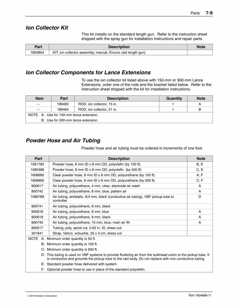
Ion Collector Kit This kit installs on the standard length gun. Refer to the instruction sheetshipped with the spray gun for installation instructions and repair parts.
Part Description Note1603854 KIT, ion collector assembly, manual, Encore (std length gun)
Ion Collector Components for Lance Extensions To use the ion collector kit listed above with 150-mm or 300-mm LanceExtensions, order one of the rods and the bracket listed below. Refer to theinstruction sheet shipped with the kit for installation instructions.
Item Part Description Quantity Note— 189483 ROD, ion collector, 15 in. 1 A
— 189484 ROD, ion collector, 21 in. 1 B
NOTE A: Use for 150-mm lance extension.
B: Use for 300-mm lance extension.
Powder Hose and Air Tubing Powder hose and air tubing must be ordered in increments of one foot.
Part Description Note1081783 Powder hose, 6 mm ID x 8 mm OD, polyolefin (by 100 ft) B, E
1080388 Powder hose, 6 mm ID x 8 mm OD, polyolefin (by 500 ft) C, E
1606690 Clear powder hose, 6 mm ID x 8 mm OD, polyurethane (by 100 ft) A, F
1606695 Clear powder hose, 6 mm ID x 8 mm OD, polyurethane (by 500 ft) C, F
900617 Air tubing, polyurethane, 4 mm, clear, electrode air wash A
900742 Air tubing, polyurethane, 6 mm, blue, pattern air A
1096789 Air tubing, antistatic, 6/4 mm, black (conductive air tubing), VBF pickup tube tocontroller
D
900741 Air tubing, polyurethane, 6 mm, black
900618 Air tubing, polyurethane, 8 mm, blue A
900619 Air tubing, polyurethane, 8 mm, black A
900740 Air tubing, polyurethane, 10 mm, blue, main air IN A
900517 Tubing, poly, spiral cut, 0.62 in. ID, dress out
301841 Strap, Velcro, w/buckle, 25 x 3 cm, dress out
NOTE A: Minimum order quantity is 50 ft.
B: Minimum order quantity is 100 ft.
C: Minimum order quantity is 500 ft.
D: This tubing is used on VBF systems to provide fluidizing air from the bulkhead union to the pickup tube. Itis conductive and grounds the pickup tube to the cart body. Do not replace with non-conductive tubing.
E: Standard powder hose delivered with system.
F: Optional powder hose to use in place of the standard polyolefin.

Parts7-10
Part 1604869-11 � 2018 Nordson Corporation

EU DECLARATION of Conformity Product: Encore XT / HD Manual Powder Spray Systems Models: Encore XT Manual, Fixed Mount or Mobile Dolly unit. Encore Auto Applicator with Encore XT controls for a single gun automatic systems. Encore HD Manual, Fixed Mount or Mobile Dolly unit. Description: These are all electrostatic, powder spray systems, including applicator, control cables and associated controllers. The Encore XT Manual system uses venturi style pump technology for supplying power to the spray gun. While the Encore HD Manual system uses high density pump technology for supplying power to the spray gun. The Encore Auto Gun is listed with Manual XT controls for single auto gun applications and could be mounted to a gun stand or on a robot. Applicable Directives: 2006/42/EC - Machinery Directive 2014/30/EU - EMC Directive 2014/34/EU - ATEX Directive Standards Used for Compliance: EN/ISO12100 (2010) EN60079-0 (2014) EN61000-6-3 (2007) FM 7260 (1996) EN50050-2 (2013) EN1953 (2013) EN60079-31 (2014) EN61000-6-2 (2005) EN55011 (2009) EN60204-1 (2006) Principles: This product has been designed & manufactured according to the Directives & standards / norms described above. Type of Protection: - Ambient Temperature: +15ºC to +40ºC - Ex tb IIIB T60ºC / Ex II 2 D / 2mJ = (Encore XT and HD Applicators) - Ex tc IIIB T60ºC / EX II (2) 3 D = (Controllers) - Ex II 2 D / 2mJ = (Encore Auto Applicator) Certificates: - FM14ATEX0051X = Encore XT and HD Manual Applicators (Norwood, Mass. USA) - FM14ATEX0052X = Controls (Norwood, Mass. USA) - FM11ATEX0056X = Encore Automatic Applicator (Norwood, Mass. USA) ATEX Surveillance - 1180 SGS Baseefa (Buxton, Derbyshire, UK)
Date: 30 NOV 2017 Vance Wilson Engineering Manager Industrial Coating Systems Amherst, Ohio, USA Nordson Authorized Representative in the EU Contact: Operations Manager Industrial Coating Systems Nordson Deutschland GmbH Heinrich-Hertz-Straße 42-44 D-40699 Erkrath
Nordson Corporation Westlake, Ohio DOC14034-05
CRITICALNo revisions permitted withoutapproval of the proper agency.
CONTROLLER INTERFACE CABLE1080718-10FT.1609709-50FT.1080719-30IN.
6M HANDGUN CABLE EXTENSION,6-CONDUCTOR, SHIELDED.
1085168
ENCORE XT CONTROLLER POWER UNIT1082815 FOR 230V VBF1600468 FOR 115V VBF
10
14
14
ENCORE XT/HD 6M HANDGUNCABLE ASSEMBLY1600745
11
ENCORE XT HANDGUN1600818
A0812
ENCORE XT/HD INTERFACE CONTROL UNIT1604125
13 14
ENCORE HD CONTROLLER POWER UNIT W/HD OR HD+ PUMP
WITH HD PUMP1605586 FOR 230V VBF 1605584 FOR 115V VBF
WITH HD+ PUMP1611089 FOR 230 VBF1611086 FOR 115 VBF
14
ENCORE AUTOMATIC GUN - 1097489OPTIONAL 90 DEGREE EXTENSION- 1604084ENCORE AUTOMATIC GUN CABLE - 1605436 14
ENCORE HD HYBRIDPOWER UNIT W/PRODIGY PUMP1606978 FOR 230V VBF1606977 FOR 115V VBF
OPTIONAL POS KVMULTIPLIER
160904816
A05
A07
A08
09
12
12
13
13
ENCORE HD HANDGUN1603160
14
14
15
15
15
17
17
17
8
A
7 6 5
THIS DRAWING IS NORDSON PROPERTY,CONTAINS PROPRIETARY INFORMATION AND MUST BE RETURNED UPON REQUEST.DO NOT CIRCULATE, REPRODUCE OR DIVULGE TO OTHER PARTIES WITHOUT WRITTEN CONSENT OF NORDSON.
B
C
D
NOTICE8 7 6 5
4 3 2 1
A
4 3 1084547 1
B
C
D
FILE NAME MATERIAL NO. REVISION
SCALE
ALL DIMENSIONS IN
SOLIDWORKS GENERATED DWG.
NORDSON CORPORATIONWESTLAKE, OH, U.S.A. 44145
DRAWN BY
CHECKED BY
MMEXCEPT AS NOTED
THIRD ANGLEPROJECTION
X±0.8 X.X±0.25
MACHINED SURFACES 1.6
BREAK INSIDE/OUTSIDE CORNERS0.1/0.8
THREAD LENGTH DIMENSIONS AREFULL THREAD
INTERPRET DRAWINGS PER ASMEY14.5-1994
PERFECT FORM AT MMC REQUIREDFOR INTERRELATED FEATURES
DESCRIPTION
DATE
APPROVED BY
RELEASE NO.
SIZE
MATERIAL NO. REVISION
DRJ 11JAN08PE600468
D 1084547_PDF 1084547 17NOT TO SCALE 1 OF 2SHEET
17
X.XX±0.13
RJF RJF
REF DWG,APVD EQUIP,MANUAL ENCORE XT HD
CRITICALNo revisions permitted withoutapproval of the proper agency.
CONTROLLER INTERFACE CABLE1080718-10 FT.1609709-50FT.1080719-30 IN.
115V VIBRATOR MOTOR 1604511230V VIBRATOR MOTOR 1080950
WITH EXTRA-HARD USAGE ELECTRICAL CORDUL/CSA APPROVED 18 AWG 90 C
MANUFACTURER'S CERT. #: TUV12ATEX094817ALSO: ETL CERTIFIED FOR U.S & CANADA
A04
ENCORE 115V 60Hz & 230V 50Hz VBFMOBILE POWDER SYSTEMS
1600827 OR 1600828HEIGHT: 1078 [42.5]
WEIGHT: 50.8kg [112lbs]wheel base: 620 [24.4] L X 511.5 [20.1] W
ENCORE HD 115V & 230V VBFMOBILE POWDER SYSTEMS
1605588 OR 1605589 FOR HD PUMP1611076 OR 1611079 FOR HD+ PUMP
HEIGHT: 1078 [42.5]WEIGHT: 50.8kg [112lbs]
wheel base: 620 [24.4] L X 511.5 [20.1] W
ENCORE HD 115V & 230V HYBRID VBF (WITH PRODIGY) MOBILE POWDER SYSTEMS
1606274 OR 1606275HEIGHT: 1078 [42.5]
WEIGHT: 50.8kg [112lbs]wheel base: 620 [24.4] L X 511.5 [20.1] W
ENCORE XT 50LB HOPPERMOBILE POWDER SYSTEM
1600829HEIGHT: 1078 [42.5]
WEIGHT: 54.4kg [120lbs]wheel base: 620 [24.4] L X 511.5 [20.1] W
ENCORE HD 50LB HOPPERMOBILE POWDER SYSTEMS
1605587 FOR HD PUMP1611246 FOR HD+ PUMP
HEIGHT: 1078 [42.5]WEIGHT: 54.4kg [120lbs]
wheel base: 620 [24.4] L X 511.5 [20.1] W
ENCORE HD HYBRID 50LB HOPPERMOBILE POWDER SYSTEMS (WITH PRODIGY)
1606273HEIGHT: 1078 [42.5]
WEIGHT: 54.4kg [120lbs]wheel base: 620 [24.4] L X 511.5 [20.1] W
ENCORE XT 25LB HOPPERMOBILE POWDER SYSTEM
1600830HEIGHT: 1078 [42.5]
WEIGHT: 53kg [117lbs]wheel base: 620 [24.4] L X 511.5 [20.1] W
A08
A04
10
11
12
12
12
12
12
13
13
14
14
14
14
17
17
17
17
8
A
7 6 5
THIS DRAWING IS NORDSON PROPERTY,CONTAINS PROPRIETARY INFORMATION AND MUST BE RETURNED UPON REQUEST.DO NOT CIRCULATE, REPRODUCE OR DIVULGE TO OTHER PARTIES WITHOUT WRITTEN CONSENT OF NORDSON.
B
C
D
NOTICE8 7 6 5
4 3 2 1
A
4 3 1084547 1
B
C
D
FILE NAME MATERIAL NO. REVISION
SCALE
ALL DIMENSIONS IN
REF DWG,APVD EQUIP,MANUAL ENCORE XT HD
SOLIDWORKS GENERATED DWG.
NORDSON CORPORATIONWESTLAKE, OH, U.S.A. 44145
DRAWN BY
CHECKED BY
MMEXCEPT AS NOTED
THIRD ANGLEPROJECTION
X±0.8 X.X±0.25
MACHINED SURFACES 1.6
BREAK INSIDE/OUTSIDE CORNERS0.1/0.8
THREAD LENGTH DIMENSIONS AREFULL THREAD
INTERPRET DRAWINGS PER ASMEY14.5-1994
PERFECT FORM AT MMC REQUIREDFOR INTERRELATED FEATURES
DESCRIPTION
DATE
APPROVED BY
RELEASE NO.
SIZE
MATERIAL NO. REVISION
DRJ 11JAN08PE600468
D 1084547_PDF 1084547 17NOT TO SCALE 2 OF 2SHEET
17
X.XX±0.13
RJF RJF