Embed Size (px)
Citation preview
Vo 19 No 9
RADIO TELEVISIOW ELECTRONICS AUDIO
APRIL 1966
2/3
Transistorised A.C. Millivoltmeter
Receiver Circuit Economy Parking Home or Office *, Single Transistor for Caravans Light Controller Intercom System Audio Oscillator
www.americanradiohistory.com
Eddystone RECEIVER I
OF MAJOR INTEREST TO ALL RADIO ENTHUSIASTS
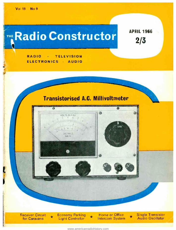
EC 10 transistorized communications receiver A most efficient transistorized communications receiver of light weight, compact dimensions, and capable of a really good performance. Five ranges give continuous coverage from 550 kc /s to 30 Mc /s (545 to 10 metres), and included are the medium -wave broad- cast band, the marine (coastal) band from 1500 to 3000 kc /s, and all the short -wave broadcast bands. Also available are the six major amateur bands and many services in between.
The EC10 receiver accepts normal AM telephony and CW telegraphy, a special filter being provided to increase selectivity (and also reduce noise) in the CW mode, as is often desirable. Single sideband signals can
be successfully resolved by appropriate setting of the BFO for carrier reinsertion. A total of 13 transistors and diodes is used, leading to high sensitivity and con- sistent results on all ranges. The main scales occupy a length of nine inches and are clearly calibrated direct in frequency. The standard Eddystone precision slow - motion drive controls the tuning, which is exceptionally smooth and light to handle. An auxiliary logging scale permits dial settings of chosen stations to be recorded.
An internal speaker gives good aural quality and a comparatively high audio output is available -one can easily believe '..he set is mains operated. For personal listening, a telephone headset can be plugged into the socket on the front panel, the speaker then being out of action.
Alternative aerial sockets are provided, for dipole, long wire, or short rod or wire. Power is derived from six cells housed in a separate detachable compartment. Current consumption is related to audio output and, for long life, HP2 -type heavy -duty cells are recom- mended.
The receiver is housed in a metal cabinet, and, with robust construction throughout, it will stand up to hard usage over a long period with a high degree of reliability. The finish is an attractive two -tone grey. The dimen- sions are width 122 ", height 64 ", depth 8 "; weight with batteries is 14 lb.
Eddystone Radio Limited Eddystone Works, Alvechurch Road, Birmingham 31
Telephone: Priory 2231 Cables: Eddystone Birmingham Telex: 33708 LTD/ED5
www.americanradiohistory.com
FRE TOAMR1TIOUSENG/NFFRS - THE LATEST EDITION OF ENGINEERING OPPORTUNITIES
Have you sent for your copy ?
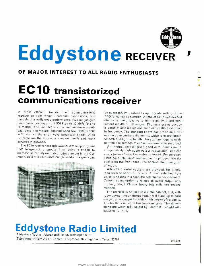
ENGINEERING OPPORTUNITIES is a highly informative 156 -page guide to the best paid engineering posts. It tells you how you can quickly prepare at home for a recognised engineering quali- fication and outlines a wonderful range of modern Home Study Courses in all branches of Engineering. This unique book also gives full details of the Practi- cal Radio & Electronics Courses, ad- ministered by our Specialist Electronics Training Division -the B.I.E.T. School of Electronics, explains the benefits of our Employment Dept. and shows you how to qualify for five years' promotion in one year.
SATISFACTION OR REFUND OF FEE
Whatever your age or experience, you cannot afford to miss reading this famous book. If you are earning less than £30 a week, send for your copy of "ENGINEERING OPPORTUNITIES" today -FREE.
WHICH IS YOUR PET SUBJECT? Mechanical Eng., Electrical Eng.,
Civil Engineering, Radio Engineering, Automobile Eng., Aeronautical Eng., Production Eng., Building, Plastics, Draughtsmanship,
Television, etc.
GET SOME LETTERS AFTER YOUR NAME!
A.M.1.Mech.E. A. M.I.C. E.
A. M.I. Prod. E. A. M.I. M.I.
A.I.O.B. B.Sc.
A.M.I. E. R.E. City & Guilds
Gen. Cert. of Ed. Etc., etc.
BRITISH INSTITUTE OF ENGINEERING TECHNOLOGY (Dept. 752B), 29 Wright's Lane, London, W.8
PRACTICAL EQUIPMENT
Basic Practical and Theore- tic Courses for beginners in Radio, T.V., Electronics, Etc., A.M.I.E.R.E., City &
Guilds Radio Amateurs' Exam.
R.T.E.B. Certificate P.M.G. Certificate
Practical Radio Radio & Television
Servicing Practical Electronics
Electronics Engineering Automation
INCLUDING TOOLS!
The specialist Elec- tronics Division of B.I.E.T. NOW offers you a real laboratory training at home with practical equipment. Ask for details.
B.I.E.T. SCHOOL OF
ELECTRONICS
POST COUPON NOW! Please send me your FREE 156 -page
"ENGINEERING OPPORTUNITIES" (Write if you prefer not to cut page)
NAME
ADDRESS
SUBJECT OR EXAM THAT INTERESTS ME
R
752B g
THE B.I.E.T. IS THE LEADING INSTITUTE OF ITS KIND IN THE WORLD
L.P. RECORDING TAPE
BARGAIN OFFER! By leading British manufacturers -
PROFESSIONAL GRADE - DOUBLE -SIDED (each side coated) 5e" reels only
SPECIAL 1,450 feet (2 reels)
PRICE 20/- post free Ideal for the experimenter who wants to record both sides, and a good L.P. Tape for the enthusiast who wishes to record single side only.
SPECIAL OFFER. 3" Message tape 150', 3/9; 3" L.P. 225', 4/9; 3" D.P. 300', 6/6. P. & P. per reel 6d. TAPE REELS. Mnfrs. surplus 7 ", 2/3; 51",2/-; 5 ", 2/ -; 3 ", 1/3; Plastics spool containers, 5 ", 1/9; 51 ", 2/ -; 7 ", 2/3.
TYGAN FRET (Contem. pat.), 12 x 12 ", 2/ -; 12 x 18 ", 3/ -; 12 x 24 ", 4/ -, etc. EXPANDED ANODISED METAL -Attractive gilt finish }" x f" diamond mesh 4/6 sq. ft. Multiples of 6" cut. Max. size 4' x 3', 47/6 plus carr. BONDACOUST Speaker Cabinet Acoustic Wadding (I" thick approx.) 18" wide, any length cut, 6/- yd.
ENAMELLED COPPER WIRE -*lb. reels 14g -20g, 3/ -; 22g -28g, 3/6; 30g -34g, 4/3; 36g -38g, 4/9; 39g -40g, 5/ -, etc. TINNED COPPER WIRE. 16 -22g, 4/- fIb. ERSIN MULTICORE SOL- DER, 60/40, 4d. per yard, Cartons 6d., II -, 2/6, etc.
APRIL 1966
6 VALVE AM /FM TUNER UNIT Med. and VHF 190m -550m, 86 Mc /s- 103 Mc /s, 6 valves and metal rectifier. Self- contained power -unit, A.C. 200 /250V operation. Magic -eye indicator, 3 push- button controls, on /off, Med., VHF. Diode and high output Sockets with gain control. Illuminated 2- colour perspex dial I If" x 4 ", chassis size I I }" x 4" x 51 ". A recommended Fidelity Unit for use with Mullard "3 -3" or "5 -10" Amplifiers. Complete kit of parts, inc. Power Pack, L10.19.6, carriage and insurance as illustrated. Carr. 7/6. Circuit and constr's details, 4/6 Free with kit.
MULLARD "3 -3" & "5 -10" HI -FI AMPLIFIERS 3 OHM & 15 OHM OUTPUT "3 -3" Amp. 3- valve, 3 watt Hi -Fi quality at reasonable cost. Bass Boost and Treble controls, quality sectional output transformer, 40 c /s -25 kc, /s i IdB. 100mV for 3W, less than I% distortion. Bronze escutcheon panel. Complete Kit only 7 gns. Carr. 5/ -. Wired and tested L8.10.0. MULLA RD "5 -I0" AMPLIFIER -5 valves IOW, 3 and 15 ohms output. Mallard's famous circuit with heavy duty ultra- linear quality output tfr. Basic amplifier kit price L9.19.6. Carr. 7/6. Ready built I If gns. 2 -VALVE PRE -AMP. UNIT Based on Mullard's famous 2 -valve (2 x EF86) circuit with full equalisation with volume, bass, treble, and 5- position selector switch. Size 9" x 6" x 2 } ". Ready built, wired and tested, L7.19.6. Carr. 3/6.
Condensers -Silver Mica. All values 2pF to I,000pF, 6d. each. Dittos Ceramics, 9d. Tub, 450V T.C.C. etc. 0.001 mFd to 0.01 nd 0. /I 350V, 9d. 0.0- 0.1 /500V, 1 /a. 0.25 Hunt, 1/6. 0.25 T.C.C., 1/9, etc., etc. Close Tel. S /Micas -10% 5pF- 500pF, 8d. 600- 5,000pF, 1 / -, I
2pF- 100pF, 9d. 100pF- 500pF, I Id. 575pF- 5,000pF, 1/6. Resistors -Full Range 10 ohms -10 meg. ohms 20% } and fW, 3d., }W, 5d. (Midget type modern rating) I W, 6d., 2W, 9d. Hi -Stab. 5% fW, fW, 6d. (100 ohms -I meg) Other values 9d, 1% }W, 1/6, etc., etc.
TRANSISTOR COMPONENTS Midget I.F.'s -465 kc /s" diam., first, second or third 5/6 Osc. coil M. & L.W. ,'x" diam. 5/- Midget Driver Trans. 9:1 6/- Ditto 0/Put Push -pull 3 ohms 6/- Elect Condensers -Midget Type I5V I mfd- 50mfd, ea. 1/9. 100mfd, 2/ -. 15 choke, 2/6. Ferrite Aerial -M. & L. W. with ca aerial coupling coil, 9/3. Condensers -150V wkg. .01mfd. to 04mfd., 9d..05mfd., .Imfd., 1 /- ..25mfd., 1/3. .5mfd., 1/6, etc Tuning Cond s. J.B. "00" 208+ 176pF, 8/6. Ditto with trimmers, 9/6. 365pF single, 7/6. Sub -min. ;" DILEMIN 100pF, 300pF, 500pF, 7/ -. Midget Vol. Control with edge control knob, Skit with switch, 4/9, ditto less switch, 3/9.
TUB -E LECTRO LYTICS -CAN 25/25V, 50/12V, 1/9; 8 +8/450V, 4/6; 50/50V, 100/125V, 2/ -; 32 +32/275V, 4/6; 8/450V, 4/350V, 2/3; 50/50/350V, 6/6; 16 +16/450V, 5/6; 60/250/275V, 12/6; 32 +32/450V, 6/6; 100 +200 /275V, 12/6.
Volume Controls -5K -2 Meg - ohms, 3" Spindles Morganite Midget Type. If" diam. Guar. I year. LOG or LIN ratios less Sw., 3/6. DP. Sw. 51 -. Twin Stereo less Sw., 7/6. D.P. Sw., 9/6 (100 k to 2 Meg. only). 4, Meg. VOL Controls D.P. 5w.
flatted spindle. Famous Mfrs. 4 for 10 /- post free.
Send for detailed bargain lists, 3d. stamp. We manu- facture all types Radio Mains Transi. Chokes. Quality 0/P Trans., etc. Enquiries invited for Specials, Proto- types for small production runs. Quotation by return. RADIO COMPONENT SPECIALISTS 70 Brigstock Road, Thornton Heath, Surrey THO 2188. Hours: 9 a.m. -6 p.m., I p.m. Wed. Terms C.W.O. or C.O.D. Post and Packing up to fib., I / -, I lb. 1/9, 31b., 3/ -, SIb. 3/9, Bib., 4/6.
Jack Plugs. Standard 2f" Igranic Type, 2/6. Screened Ditto, 3/3. Mini- ature scr. If ", 2/3. Sub -min., 1/3. Jack Sockets. Open Igranic Moulded Type, 3/6. Closed Ditto, 4/ -. Miniature Closed Type, 1/6. Sub -min. (deaf aid) ditto, 1/6. Stereo Jack Sockets, 3/6. Stereo Jack Plugs, 3/6. Phono Plugs, 9d. Phono Sockets (open), 9d. Ditto (closed), 1 / -. Twin Phono Sockets (open), 1/3.
529
www.americanradiohistory.com
20 +20 STEREO
AMP. AA -22U
HI -FI AMPLIFIERS TUNERS - RECORD PLAYERS
GARRARD PLAYER
AT -60
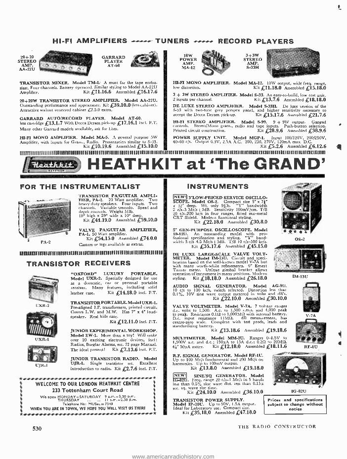
TRANSISTOR MIXER. Model TM -1. A must for the tape enthu- siast. Four channels. Battery operated. Similar styling to Model AA -22U Amplifier. Kit £11.16.6 Assembled £16.17.6
20 +20W TRANSISTOR STEREO AMPLIFIER. Model AA -22U. Outstanding performance and appearance. Kit £39.10.0 (less cabinet). Attractive walnut veneered cabinet £2.5.0 extra.
GARRARD AUTO/RECORD PLAYER. Model AT -60. less cartridge £13.1.7 With Decca Deram pick -up £17.16.1 incl. P.T. Many other Garrard models available, ask for Lists.
HI-FI MONO AMPLIFIER. Model MA -5. A general purpose 5W Amplifier, with inputs for Gram., Radio. Presentation similar to S -33.
Kit £10.19.6 Assembled £15.10.0
10W POWER
AMP. MA -12
3 +3W STEREO
AMP. S-33H
HI-FI MONO AMPLIFIER. Model MA-12. IOW output, wide freq. range, low distortion. Kit £11.18.0 Assembled £15.18.0 3 + 3W STEREO AMPLIFIER. Model S-33. An easy -to-build, low cost unit. 2 inputs per channel. Kit £13.7.6 Assembled £18.18.0 DE LUXE STEREO AMPLIFIER. Model S-33H. De luxe version of the S -33 with two -tone grey perspex panel, and higher sensitivity necessary to accept the Decca Deram pick -up. Kit £15.17.6 Assembled £21.7.6 HI -FI STEREO AMPLIFIER. Model S-99. 9 + 9W output. Ganged controls. Stereo /Mono gram., radio and tape inputs. Push- button selection. Printed circuit construction. Kit £28.9.6 Assembled £38.9.6 POWER SUPPLY UNIT. Model MGP -1. Input 100 /120V, 200/250V, 40-60 c /s. Output 6.3V, 2.5A A.C. 200, 250, 270V, 120mA max. D.C.
Kit £5.2.6 Assembled £6.12.6
' r" ,r. H EAT H K I T at 'The GRAND' FOR THE INSTRUMENTALIST
TRANSISTOR PA /GUITAR AMPLI- FIER, PA -2. 20 Watt amplifier. Two heavy duty speakers. Four inputs. Two channels. Variable tremolo. Speed and depth controls. Weight 511b. 18" high x 29" wide x 10" deep.
Kit £44.19.0 Assembled £59.10.0
VALVE PA /GUITAR AMPLIFIER, PA -1. 50 Watt amplifier.
Kit £54.15.0 Assembled £74.0.0 Castors or legs available as extras.
BIZE
TRANSISTOR RECEIVERS
UXR-2
UXR-1
UJR-1
"OXFORD" LUXURY PORTABLE. Model UXR -2. Specially designed for use as a domestic, car or personal portable receiver. Many features, including solid leather case. Kit £14.18.0 incl. P.T.
TRANSISTOR PORTABLE. Model UXR -1. Pre -aligned I.F. transformers, printed circuit. Covers L.W. and M.W. Has 7" x 4" loud- speaker. Real hide case.
Kit £12.11.0 incl. P.T.
JUNIOR EXPERIMENTAL WORKSHOP. Model EW -1. More than a toy! Will make over 20 exciting electronic devices, incl: Radios, Burglar Alarms, etc. 72 page Manual. The ideal present! Kit £7.13.6 incl. P.T.
JUNIOR TRANSISTOR RADIO. Model UJR -1. Single transistor set. Excellent introduction to radio. Kit £2.7.6 incl. P.T.
WELCOME TO OUR LONDON HEATHKIT CENTRE
233 Tottenham Court Road We open MONDAY -SATURDAY 9 a.m. -5.30 p.m.
THURSDAY ... ... I I a.m. -2.30 p.m. Telephone No: MUSeum 7349
WHEN YOU ARE IN TOWN, WE HOPE YOU WILL VISIT US THERE
530
INSTRUMENTS NEW! 3 "LOW -PRICED SERVICE OSCILLO- COPE. Model OS-2. Compact size 5" x 71"
x 12" deep. Wt. only 4lb. "Y" bandwidth 2 c /s -3 Mc /s±3dB. Sensitivity 100mV /cm. T/B 20 c/s -200 kc /s in four ranges, fitted mu -metal CRT Shield. Modern functional styling.
Kit £22.18.0 Assembled £30.8.0 5" GEN- PURPOSE OSCILLOSCOPE. Model 10 -12U. An outstanding model with pro- fessional specification and styling. "Y" band- width 3 c /s-4.5 Mc /s+3dB. T/B 10 c /s-500 kc /s.
Kit £35.17.6 Assembled £45.15.0
DE LUXE LARGE -SCALE VALVE VOLT- METER. Model IM -13U. Circuit and speci- fication based on the well -known model V -7A but with many worth -while refinements. 6" Ernest Turner meter. Unique gimbal bracket allows operation of instrument in many positions. Modern styling. Kit £18.18.0 Assembled £26.18.0
AUDIO SIGNAL GENERATOR. Model AG-9U. 10 c/s to 100 kc /s, switch selected. Distortion less than 0.1 %, 10V sine wave output metered in volts and dB's.
Kit £22.10.0 Assembled £30.10.0
VALVE VOLTMETER. Model V -7A. 7 voltage ranges d.c. volts to 1,500. A.c. to 1,500 r.m.s. and 4,000 peak to peak. Resistance 0.10 to 1,000M0 with internal battery. D.c. input resistance 11M0. dB measurement, has centre -zero scale. Complete with test prods, leads and standardising battery.
Kit £13.18.6 Assembled £19.18.6
MULTIMETER. Model MM -1U. Ranges 0 -1.5V to 1,500V a.c. and d.c.; 150µA to 15A d.c.; 0.20 to 20M0. 44" 50µA meter. Kit £12.18.0 Assembled £18.11.6
OS-2
R.F. SIGNAL GENERATOR. Model RF -1U. Up to 100 Mc /s fundamental and 200 Mc /s on harmonics. Up to 100mV output.
Kit £13.8.0 Assembled £19.18.0
SINE /SQ GENERATOR. Model U. Freq. range 20 c /s-1 Mc /s in 5 bands
less than 0.5% sine wave dist. less than 0.l5µ sec. sq. wave rise time.
Kit £24.10.0 Assembled £36.10.0
TRANSISTOR POWER SUPPLY. Model IP -20U. Up to 50V, 1.5A output. Ideal for Laboratory use. Compact size.
Kit £35.18.0 Assembled £47.18.0
IM-13U
V-7A
RF-1U
IG-82U
Prices and specifications subject to change without
notice
THE RADIO CONSTRUCTOR
s
www.americanradiohistory.com
TAPE AMPLIFIERS
FM TUNER FM -4U
.111,1 TAPE DECKS - CONTROL UNITS
MAGNAVOX DECK
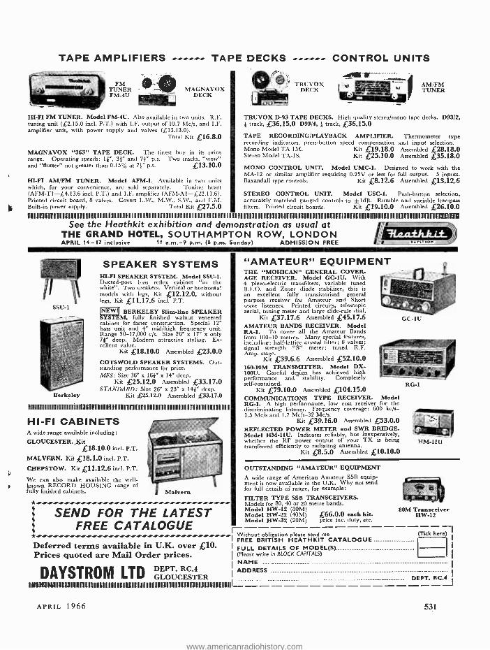
III -FI FM TUNER. Model FM-4U. Also available in two units. R.F. tuning unit (£2.15.0 incl. P.T.) with I.F. output of 10.7 Mc /s, and I.F. amplifier unit, with power supply and valves (£13.13.0).
Total Kit £16.8.0
MAGNAVOX "363" TAPE DECK. The finest buy in its price range. Operating speeds: 11 ", 3 }" and 71" p.s. Two tracks, "wow" and "flutter" not greater than 0.15°ó at 71" p.s. £13.10.0
HI-FI AM /FM TUNER. Model AFM -I. Available in two units which, for your convenience, are sold separately. Tuning heart (AFM -T1- £4.13.6 incl. P.T.) and I.F. amplifier (AFM -Al- £22.11.6). Printed circuit board, 8 valves. Covers L.W., M.W., S.W., and F.M. Built -in power supply. Total Kit £27.5.0
TRUVOX DECK
AM /FM TUNER
TRUVOX D-93 TAPE DECKS. High quality stereo /mono tape decks. D93/2, 1 track, £36.15.0 D93/4, } track, £36.15.0
TAPE RECORDING /PLAYBACK AMPLIFIER. Thermometer type recording indicators, press- button speed compensation and input selection. Mono Model TA -I M. Kit £19.18.0 Assembled £28.18.0 Stereo Model TA -1S. Kit £25.10.0 Assembled £35.18.0
MONO CONTROL UNIT. Model UMC-1. Designed to work with the MA -12 or similar amplifier requiring 0.25V or less for full output. 5 inputs. Baxandall type controls. Kit £8.12.6 Assembled £13.12.6
STEREO CONTROL UNIT. Model USC.1. Push- button selection, accurately matched ganged controls to ± 1dB. Rumble and variable low -pass filters. Printed circuit boards. Kit £19.10.0 Assembled £26.10.0
See the Heathkit exhibition and demonstration as usual at THE GRAND HOTEL, SOUTHAMPTON ROW, LONDON APRIL 14 -17 inclusive 11 a.m. -9 p.m. (8 p.m. Sunday) ( P y) ADMISSION FREE ro..:TSO.,
SSU-1
Berkeley
SPEAKER SYSTEMS HI-FI SPEAKER SYSTEM. Model SSU -1. Ducted -port bass reflex cabinet "in the white ". Two speakers. Vertical or horizontal models with legs, Kit 12.12.0, without legs, Kit £11.17.6 inc r. P.T.
BERKELEY Slim -line SPEAKER SY T , fully finished walnut veneered cabinet for faster construction. Special 12" bass unit and 4" mid /high frequency unit. Range 30- 17,000 c /s. Size 26" x 17" x only 7 }" deep. Modern attractive styling. Ex- cellent value.
Kit £18.10.0 Assembled £23.0.0 COTSWOLD SPEAKER SYSTEMS. Out- standing performance for price. MFS: Size 36" x 161" x 14" deep.
Kit £25.12.0 Assembled £33.17.0 STANDARD: Size 26" x 23" x 141" deep.
Kit £25.12.0 Assembled £33.17.0
1NAlIIIIIiIIIIIIIIIhIII1tl11
HI -FI CABINETS A wide range available including:
GLOUCESTER. ,7$it £18.10.0 incl. P.T.
MALVERN. Kit £18.1.0 incl. P.T.
CHEPSTOW. Kit £11.12.6 incl. P.T.
We can also make available the well - known RECORD HOUSING range of fully finished cabinets.
* .I' I,...NN..IIINNN SEND FOR THE LATEST
FREE CATALOGUE *Neeee Deferred terms available in U.K. over £10. Prices quoted are Mail Order prices.
DAYSTROM LTD 111111(IH11IdnIiIIIIYYIIIIII01IiI11uIIIIIIl111111111111111N11111111111111111111111I IIIIIIIIIIIIIII II11IIIIIIIIIIIIIIIIIIIIII IIIIIIIIIIIIIIII11IIIIIIIIIIIIIIIIIIIIIIIIIII11IIIIIIIIIIIIIU11111111111111111111111111I
DEPT. RC.4 GLOUCESTER
"AMATEUR" EQUIPMENT THE "MOHICAN" GENERAL COVER- AGE RECEIVER. Model GC -1U. With 4 piezo- electric transfilters, variable tuned B.F.O. and Zener diode stabiliser, this is an excellent fully transistorised general purpose receiver for Amateur and Short wave listeners. Printed circuits, telescopic aerial, tuning meter and large slide -rule dial.
Kit £37.17.6 Assembled £45.17.6 AMATEUR BANDS RECEIVER. Model RA -1. To cover all the Amateur Bands from 160-10 metres. Many special features, including: half -lattice crystal filter; 8 valves; signal strength "S" meter; tuned R.F. Amp. stage.
Kit £39.6.6 Assembled £52.10.0 160 -10M TRANSMITTER. Model DX- 100U. Careful design has achieved high performance and " stability. Completely self -contained.
Kit £79.10.0 Assembled £104.15.0 COMMUNICATIONS TYPE RECEIVER. Model RG-1. A high performance, low cost receiver for the discriminating listener. Frequency coverage: 600 kc /s- 1.5 Mc /s and 1.7 Mc /s-32 Mc /s.
Kit £39.16.0 Assembled £53.0.0 REFLECTED POWER METER and SWR BRIDGE. Model HM -11U. Indicates reliably, but inexpensively, whether the RF power output of your TX is being transferred efficiently to radiating antenna.
Kit £8.5.0 Assembled £10.10.0
GC-1U
RG-1
HM-11U
OUTSTANDING "AMATEUR" EQUIPMENT
A wide range of American Amateur SSB equip- ment is now available in the U.K. Why not send for full details of range, for example:
FILTER TYPE SSB TRANSCEIVERS. Models for 80, 40 or 20 metre bands. Model HW -12 (80M) Model HW -22 (40M) £66.0.0 each Lit. Model HW -32 (20M) price inc. duty, etc.
80M Transceiver 11W -12
Without obligation please send me I FREE BRITISH HEATHKIT CATALOGUE I FULL DETAILS OF MODEL(S) _ .....................
I (Please write in BLOCK CAPITALS)
I NAME .....,
ADDRESS
APRIL 1966
(Tick here)
DEPT. RC.4
531
www.americanradiohistory.com
BOOKS FOU LSHAM-SAMS
JANUARY -APRIL ABC'S OF ELECTRONIC ORGANS
by Norman H. Crowhurst Demy 8vo 96 pages 16/- Net ELECTRIC GUITAR AMPLIFIER HANDBOOK
by Jack Darr Demy 8vo 144 pages 24/- Net MICROWAVE PRIMER
by Albert Camps and Joseph A. Markum, Jr. Demy 8vo 192 pages 30/- Net
PRACTICAL TRANSISTOR SERVICING New Revised Edition
by W. C. Caldwell Demy 8vo 192 pages 24/- Net SCIENCE PROJECTS IN ELECTRICITY
by Edward M. Noll Demy 8vo 144 pages 24/- Net ABC'S OF MICROWAVES
by H. Charles Woodruff Demy 8vo 96 pages 16/- Net 101 WAYS TO USE YOUR COLOUR T.V. TEST
EQUIPMENT by Robert G. Middleton Demy 8vo 144 pages 24/- Net
TRANSISTOR RADIO SERVICING MADE EASY New Revised Edition
by Wayne Lemons Demy 8vo 144 pages 20,'- Net T.V. SERVICING GUIDE
by Leslie D. Deane and Calvin C. Young, Jr. Size 11" x 81" 132 pages 22/- Net
ABC'S OF SILICON CONTROLLED RECTIFIERS by Allan Lytel Demy 8vo 128 pages 16/- Net HOW TO BUILD PROXIMITY DETECTORS AND
METAL LOCATORS by John Potter Shields Demy 8vo 128 pages 20/- Net
KNOW YOUR SIGNAL GENERATORS by Robert G. Middleton Demy 8vo 144 pages 20/- Net
T.V. DIAGNOSIS AND REPAIR by The PF REPORTER Editorial Staff
Demy 8vo 96 pages 13/6 Net BENCH SERVICING MADE EASY
by Robert G. Middleton Demy 8vo 160 pages 24/- Net COLOUR T.V. SERVICING GUIDE
by Robert G. Middleton Demy 8vo 112 pages 28/- Net KNOW YOUR SQUARE -WAVE AND PULSE
GENERATORS by Robert G. Middleton Demy 8vo 144 pages 21/- Net
TRANSISTOR ETCHED -CIRCUIT PROJECTS by James Kyle Demy 8vo 160 pages 24/- Net T.V. TROUBLESHOOTER'S REFERENCE HANDBOOK by S. Hoberman Demy 8vo 128 pages 24/- Net
Recently Published DESIGN AND OPERATION OF REGULATED POWER
SUPPLIES by Irving M. Gottlieb Demy 8vo 112 pages 24/- Net
COLOUR TELEVISION SERVICING MADE EASY byWayne Lemons and Carl Babcoke Demy 8vo 192 pages 25/- Net
ACOUSTICAL TESTS AND MEASUREMENTS by Don Davis Demy 8vo 492 pages 30/- Net
101 MORE WAYS TO USE YOUR VOM & VTVM by Robert G. Middleton Demy 8vo 128 pages 20/- Net
101 WAYS TO USE YOUR SWEEP GENERATOR by Robert G. Middleton Demy 8vo 144 pages 20/- Net
from Booksellers or, plus 8d. postage from the Publishers.
Write for complete catalogue of over 100 titles.
FOULSHAM -SAMS TECHNICAL BOOKS
Dept. CRC, Yeovil Road, Slough, Bucks, England
532
51" Std. 850ft 9/- 7" Std. 1200ft 11/6
LI FIRST QUALITY
3" LP.240ft 4/-
7" L.P. 1800ft 1811/6 6
P. & P. on each 1/6,
PVC TAPE 5" LP. 850ft 10/6 3" TP. 600ft 10/6 5" TP.1800ft 25/6
.
7 T.P. 3600ft 32/6
4 or more post free.
CYLDON U.H.F.
TUNER complete with PC.88 and PC.86 Valves. Full vari- able tuning. New and unused. Size 4}" x 51" x 11". Complete with circuit diagram. 35/- plus 2/6 P. & P.
J
.
,y
III
b. 3 to 4 WATT l AMP LIFIE R KIT
4 `k comprising chassis 8 1"
, x 2 1" x 1 ". - .. w uu bn le yra
m a i n s
transformer, output transformer, volume and tone controls, resistors, conden- sers, etc. 6V6, ECC81 and metal rectifier. Circuit 1/6, free with kit. 29/6, plus 4/6 P. & P.
8 -watt 5 -valve PUSH -PULL O AMPLIFIER & METAL RECTIFIER -' 1
' /,
Size: 9" x 6" x 11" A.C. Mains 200 -250V 5 valves. Aj ..71 For use with Std. or L.P. records, musical .'_Ô.,i, g ! instruments, all makes of pick -ups and mikes. y Output 8 watts at 5 per cent total distortion. Separate bass and treble lift controls. Two inputs, with controls, for gram. and mike. Output Transformer tapped for 3 and 15 ohms speech coils. Built and tested. L3.19 6. P. & P. 10/ -.
MUSETTE 6- Transistor Superhet Portable Radio
* 2 }" Speaker.* Output 200mw. * Plastic Cabinet in red, size 41" x 3" x If", and gold speaker louvre. * Horizontal Tuning Scale. * Internal Aerial. * IF 460 Kc /s. * All components and Tuning Assembly mounted on printed board. * Operated from PP3 Battery. * Full instructions and point -to -point wiring diagram. * Printed Circuit. * Medium and long waves.
, L r-
,
Price 39/6d P. & P. 3/6 inc. carrying strap. Circuit Dia - gram 2/6 -free with parts.
TRANSISTORISED
- f /....__---- iQ.c`{
SIGNAL GENERATOR
Size 51" x 31" x 11 ". For IF and RF alignment and AF output, 700 c/s frequency coverage 460 Kc /s to 2 Mc /s in switched frequencies. Ideal for alignment to our Elegant Seven and Musette. Built and tested. 39/6. P. & P. 3/6.
.
POWER SUPPLY KIT to purchasers orating mains transformer, etc. A.C. 200 -250V. Output 9V 50mA. 7/6d. extra.
`ELEGANT SEVEN' Mk.II Combined Portable and Car Radio The Radio with the "Star" Features * 7- transistor superhet. Output
350mW. * Wooden cabinet, fitted handle with silver coloured fittings. Size 12 }" x 8f" x 34" * Horizontal tuning scale, size 11}" 2 1" in silver and black lettering. * All stations clearly marked. * Ferrite -rod internal aerial. * I.F. Neutralisation on each stage. 460 kc /s. * D.C. coupled output stage separate A.C. negative feed back. * All components, ferrite rod and
printed board. * Operated from hensive instructions and point -to -point circuit board, back printed with all tunable over medium and long waveband. * Full after -sale service. 4" SPEAKER.
Parts list and circuit diagram Shop Hours 9 a.m. -6 p.m.
Goods not despatched outside All enquiries Stomped
RADIO & TV COMPONENTS 21F High St., Acton,
of Elegant mains
"
i
I- .i!
x
with
tuning PP9 battery.
wiring component
2/6, Early
U.K. Addressed
London,
Seven parts, incorp-
\ ; a
- ,,,
i I '
R * ONLY ..1
i 4 / O T T Plus 6/6 Post & Packing
assembly mounted on * Full compre- diagrams. * Printed
values. * Fully * Car aerial socket.
FREE with parts. Closing Wednesday Terms C.W.O.
Envelope.
(ACTON) LTD. W.3
THE RADIO CONSTRUCTOR
www.americanradiohistory.com
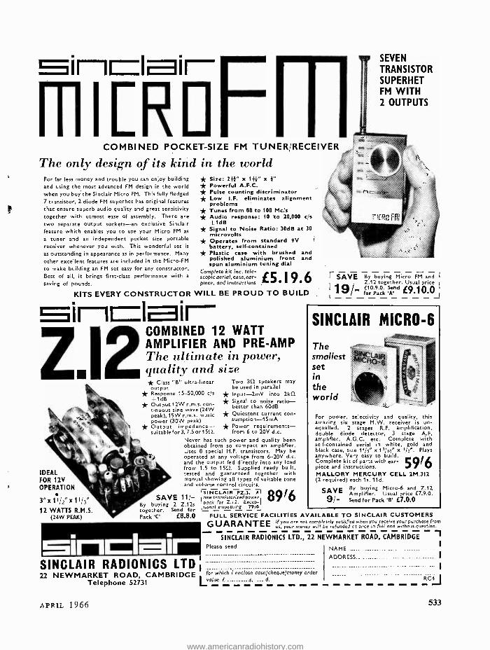
m SEVEN TRANSISTOR SUPERHET FM WITH 2 OUTPUTS
COMBINED POCKET -SIZE FM TUNER /RECEIVER
The only design of its kind in the world For far less money and trouble you can enjoy building and using the most advanced FM design in the world when you buy the Sinclair Micro FM. This fully fledged 7 transistor, 2 diode FM superhet has original features that ensure superb audio quality and great sensitivity together with utmost ease of assembly. There are
two separate output sockets -an exclusive Sinclair feature which enables you to use your Micro FM as
a tuner and an independent pocket size portable receiver whenever you wish. This wonderful set is
as outstanding in appearance as in performance. Many
other excellent features are included in the Micro -FM
to make building an FM set easy for any constructor. Best of all, it brings first -class performance with a
saving of pounds.
* Size: 2W' x 1}}" x 1" * Powerful A.F.C. * Pulse counting discriminator * Low I.F. eliminates alignment problems * Tunes from 88 to 108 Mcis * Audio response: 10 to 20,000 c/s
1dB Signal to Noise Ratio: 30dB at 30 microvolts Operates from standard 9V battery, self- contained Plastic case with brushed and polished aluminium front and spun aluminium tuning dial
Complete kit inc. tear-
piece, and instructions I / scopicaerial,case,ear-
* * *
KITS EVERY CONSTRUCTOR WILL BE PROUD TO BUILD inlair- COMBINED 12 WATT AMPLIFIER AND PRE -AMP The ultimate in power, quality and size * Class "B" ultra -linear output * Response 15- 50,000 c/s +1dB * Output 12W r.m.s. con- tinuous sine wave (24W peak), 15W r.m.s. music power (30W peak) * Output impedance- suitable for 3, 7.5 or 1552.
IDEAL FOR 12V OPERATION
3 "x11 /2 "x11 /3"
12 WATTS R.M.S. (24W PEAK)
Two 30 speakers may be used in parallel * Input -2mV into 2kO2 * Signal to noise ratio - better than 60dB * Quiescent current con - sumption-15mA * Power requirements - from 6 to 20V d.c.
Never has such power and quality been obtained from so compact an amplifier. Uses 8 special H.F. transistors. May be operated at any voltage from 6-20V d.c. and the output fed directly into any load from 1.5 to 1552. Supplied ready built, tested and guaranteed together with manual showing all types of suitable tone and volume control circuits.
'SINCLAIR PZ.3. l 8916 v new transistorized power v pock for 2.12. Excep- tional smoothing 79/6
SAVE 11/- By buying 2 Z.12s together. Send for Pack 'C' E8.8.0 FULL SERVICE FACILITIES
Sinclair SINCLAIR RADIONICS LTD 22 NEWMARKET ROAD, CAMBRIDGE for which "i enclose cash /cheque /money order
Telephone 52731 Lvalue E.. d.
E SAVE By buying Micro FM and I
Z.12 together. Usual price j
19 - E10.9.0. Send 19.10.0 for Pack 'A_
SINCLAIR MICRO -6
The smallest set in the world
For power, selectivity and quality, this amazing six stage M.W. receiver is un- equalled. 2 stages R.F. amplification, double diode detector, 3 stage A.F. amplifier, A.G.C. etc. Complete with self- contained aerial in white, gold and black case, size 14/5" x13/10" x I /z ". Plays anywhere. Very easy to build. Complete kit of parts with ear- piece and instructions. MALLORY MERCURY CELL 2M.312 (2 required) each 1s. 11d.
SAVE By buying Micro -6 and Z.12 Amplifier. Usual price E7.9.0.
9/- Send for Pack 'B' E7.0.0
AVAILABLE TO SINCLAIR CUSTOMERS
GUARANTEE If you ore not completely satisfied when you receive your purchase from us, your money will be refunded of once in full and without question.
SINCLAIR RADIONICS LTD., 22 NEWMARKET ROAD, CAMBRIDGE Ì Please send
APRIL 1966
ADDRESS....
=C4 I
533
www.americanradiohistory.com
Scottish Insurance Corporation Ltd 38 EASTCHEAP LONDON EC3
TELEVISION
SETS,
RECEIVER S
AND
TRANSMITTERS
Television Sets, Receivers and Short Wave Transmitters are expensive to acquire and you no doubt highly prize your installation. Apart from the value of your Set, you might be held responsible should injury be caused by a fault in the Set, or injury or damage by your Aerial collapsing.
A "Scottish" special policy for Television Sets, Receivers and Short Wave Transmitters provides the following cover:
(a) Loss or damage to installation (including in the case of Television Sets the Cathode Ray Tube) by Fire, Explosion, Lightning, Theft or Accidental External Means at any private dwelling- house.
(b) (i) Legal Liability for bodily injury to Third Parties or damage to their property arising out of the breakage or collapse of the Aerial Fittings or Mast, or through any defect in the Set. Indemnity £10,000 any one accident.
(ii) Damage to your property or that of your landlord arising out of the breakage or collapse of the Aerial Fittings or Mast, but not exceeding £500.
The cost of Cover (a) is 5/ a year for Sets worth £50 or less, and for Sets valued at more than £50 the cost is in proportion. Cover (b) (i) and (ii) costs only 2/6 a year if taken with Cover (a), or 5/ if taken alone.
Why not BE PRUDENT AND INSURE your installation -it is well worth while AT THE VERY LOW COST INVOLVED. If you write to the Corporation's Office a proposal will be submitted for completion.
Write for full details, quoting reference 5304, to:- THE MANAGER
SCOTTISH INSURANCE CORPORATION LTD.,
38 EASTCHEAP, LONDON E.C.3
534 THE RADIO CONSTRUCTOR
www.americanradiohistory.com
* Easily fitted * No soldering or Tchnical
knowledge necessary * Fits almost any cabinet with
minimum trouble * Modernises your old radiogram
TO PURCHASE
STEREOPHONIC
RADIOGRAM
CHASSIS
Magnificent Stereophonic Radio- gram Chassis complete with two 10"
elliptical loudspeakers, plus a Mono /Stereo 4 -speed automatic record changer.
* Built -in ferrite rod aerial * Piano key switching * Luxembourg and Caroline received at
full strength * Listen to U.S.A., Russia, Africa, Canada
and even Australia
Only £29.19.6 * Unique Lewis Radio 365 day
guarantee, even on all the valves
* All British make
SPECIAL terms available of E7.10.0 deposit followed by 18 monthly payments of E1.9.1 (total H.P. £33.13.6) + postage and packing 15/- extra.
INDIVIDUAL CABINETS SUPPLIED ON REQUEST
Send your cheque or P.O. today for £8.5.0 while stocks last to Dept. RC.1
LEWIS radio LEWIS RADIO.100,CHASE SIDE, SOUTHGATE LONDON, N.14. Telephone: PAL 3733/9666
THE WORD IS THE REGISTERED
TRADE MARK
OF DENCO (CLACTON) LIMITED
IT IS ALSO A GUARANTEE OF
WORKMANSHIP AND TECHNICAL PERFORMANCE
OUR RANGE OF PRO-
DUCTS SO GREAT THAT
WE NOW HAVE TO
REQUEST THE AMOUNT
OF 2s. Oc. FOR OUR GENER-
AL CATALOGUE AND TO
SAVE YOU POSTAL ORDER
POUNDAGE CHARGE WE
REQUEST SEND 2s. Od. IN
STAMPS.
IN RESPONSE TO CONTINUOUS DEMAND we have commenced production of Self- Contained Multiplex
Decoder Unit, aligned ready for immediate use, that will convert your two receivers -tuner and two amplifiers
-tuner and stereo amplifier or stereo receiver without Multiplex provision to a complete B.B.C. Stereo
Broadcast Reception Unit. Price £8.0.0, post paid. Technical Publication MDI, 4s. Od., post paid.
IFT.11/465 kc /s centre tapped transformer for use in crystal filter circuits, 11" x }" square. 10s. 6d. plus 8d. post.
IFT.18/465 kc /s and 1.6 Mc /s Double Tuned transistor transformer 14" x 4" square. 10s. 6d., plus 8d. post.
Please send S.A.E. with all enquiries. General Catalogue 2s. Od.
DENCO (CLACTON) LTD. (DEPT. R.C.)
357/9 OLD ROAD, CLACTON -ON -SEA, ESSEX
APRIL 1966 535
www.americanradiohistory.com
HOME RADIO LTD., Dept. RC, 187 London Road, Mitcham, Surrey Phone: MIT 3282
e\51 ale of
wo CÍtikens oR 7i
o OID FRETWORK)
This is citizen A .. .
He has just read an excellent article in a very well - known radio magazine (for title see front cover) and has decided to build the article described. He has pre- pared the list of components required. Now his troubles begin ... first, where to buy the components! He knows that shop X stocks 1% tolerance resistors, but not 1% tolerance silver mica condensers. Shop Y has 1
tolerance silver mica condensers, but not miniature transistor transformers. Shop Z has the transformers but not the other two items! Should citizen A call on X, Y and Z? This will take much of his spare time, to say nothing of the fares! Should he write to X, Y, and Z? Trouble again -he doesn't know the cost of each item and he will have to pay three lots of postage. Citizen A decides to take up fretwork!!
Why not join the many thousands of more -than- satisfied Home Radio cus- tomers? Our famous Components Cata- logue costs 7/6 plus 1/6 p. and p. Every catalogue contains 5 coupons, each worth 1/- when used as directed. Send the attached coupon today, with your cheque or P.O. for 9/ -. "It is a far far better thing than you have ever done before ".
All characters are entirely fictitious . . . we just don't know anybody named `A' or `B'!
This is citizen B . . .
He has just read the same article as A. He too has prepared his list of components. But B has a Home Radio Catalogue! In his catalogue is an Order Forni which he quickly fills in with the aid of the special price supplement supplied. Postage is no problem, because Home Radio charge a flat rate of 2/6 per parcel -whether for a resistor weighing one ounce or a trans- former weighing 20 lb. Admittedly, this is tough on citizens ordering one resistor! The answer is to plan ahead. Why pay 10 /- postage and packing for four small orders when you can get one large order for 2/6 p and p? So wise citizen B sends off his order and money, happy in the knowledge that the goods he has ordered will be despatched to him, carefully packed, within the next two or three days. He throws away his fretwork saw, and eagerly awaits the postman's knock!
r__________ ........ __I Please write your Name and Address in block capitals
Name
I Address I I I I I I I
I I
Home Radio Ltd., Dept. RC, 187 London Rd., Mitcham, Surrey FAUNS - o - M me n
536 THE RADIO CONSTRUCTOR
www.americanradiohistory.com
Radio Constructor Incorporating THE RADIO AMATEUR
Vol. 19, No. 9 Published Monthly
(1st of month)
Editorial and Advertising Offices
57 MA1DA VALE LONDON w9
Telephone CUNningham 6141
Telegrams Databux, London
First Published 1947
APRIL 1966
Receiver Circuit for Caravans, by Sir Douglas Hall, K.C.M.G., M.A.(Oxon) 538
Can Anyone Help? 540
Variable Voltage Regulated Supply with Excess Current Protection (Suggested Circuit No. 185), by G. A. French 541
Economy Parking Light Controller, by F. C. Judd, A.Inst.E 544
Single Transistor Audio Oscillator, by J. S. Brown 546
News and Comment 548
Vacuum or Solid State ?, by R. S. Thornton 550
Home or Office Intercom System, by P. J. Best 552
Recent Publications 553
The "Unity" Light Programme Receiver, by D. B. Pitt 554
Club Events 556
Finding the Velocity of Sound in Air Experimentally, by H. Lewis 557
Automatic Gramophone Cut -Out Device, by C. J. Collister 559
Solid State Microwave Oscillators 561
In Your Workshop 562
New Photon Coupled Devices, by J. B. Dance, M.Sc. 571
Transistorised AC Millivoltmeter, Part 1, by H. Smith and D. L. Woolley, B.Sc. (Cover Feature) 572
Understanding Radio, by W. G. Morley 577
Amplifiers for Transistor Voltmeters, by C. Crosbie 582
Radio Topics, by Recorder 584
© Data Publications Ltd., 1966. Contents may only be reproduced after obtaining prior permission from the Editor.
Short abstracts or references are allowable provided acknowledgement of source is given.
Annual Subscription 33s. (U.S.A. and Canada $5) including postage. Remittances should be made payable to
"Data Publications Ltd ". Overseas readers please pay by cheque or International Money Order.
Published in Great Britain by the Proprietors and Publishers Data Publications Ltd. 57 Maida Vale London W9 Printed by A. Quick 8 Co. (Printers) Ltd. Clacton -on -Sea England
APRIL 1966 537
www.americanradiohistory.com
Receiver Circuit
for Caravans
By Sir Douglas Hall K.C.M.G., M.A. (Oxon)
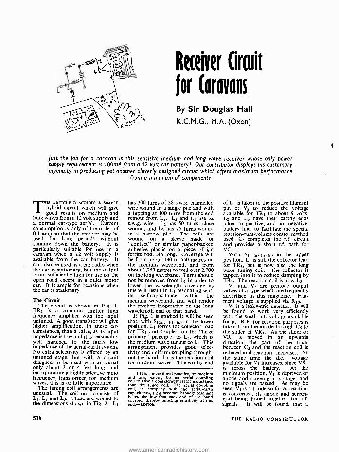
Just the job for a caravan is this sensitive medium and long wave receiver whose only power supply requirement is 100mA from a 12 volt car battery! Our contributor displays his customary ingenuity in producing yet another cleverly designed circuit which offers maximum performance
from a minimum of components
THIS ARTICLE DESCRIBES A SIMPLE hybrid circuit which will give good results on medium and
long waves from a 12 volt supply and a normal car -type aerial. Current consumption is only of the order of 0.1 amp so that the receiver may be used for long periods without running down the battery. It is particularly suitable for use in a caravan when a 12 volt supply is available from the car battery. It can also be used as a car radio when the car is stationary, but the output is not sufficiently high for use on the open road except in a quiet motor car. It is ample for occasions when the car is stationary.
The Circuit The circuit is shown in Fig. 1.
TRI is a common emitter high frequency amplifier with the input untuned. A good transistor will give higher amplification, in these cir- cumstances, than a valve, as its input impedance is low and it is reasonably well matched to the fairly low impedance of the aerial -earth system. No extra selectivity is offered by an untuned stage, but with a circuit designed to be used with an aerial only about 3 or 4 feet long, and incorporating a highly selective radio frequency transformer for medium waves, this is of little importance.
The tuning coil arrangements are unusual. The coil unit consists of LI. L2 and L3. These are wound to the dimensions shown in Fig. 2. L1
538
has 300 turns of 38 s.w.g. enamelled wire wound in a single pile and with a tapping at 100 turns from the end remote from L2. L2 and L3 use 32 s.w.g. wire. L2 has 50 turns, close wound, and L3 has 25 turns wound in a narrow pile. The coils are wound on a sleeve made of "contact" or similar paper- backed adhesive plastic on a piece of j-in ferrite rod, 3in long. Coverage will be from about 190 to 550 metres on the medium waveband, and from about 1,250 metres to well over 2,000 on the long waveband. Turns should not be removed from L1 in order to lower the wavelength coverage as this will result in L1 resonating wii'i its self -capacitance within the medium waveband, and will render the receiver inoperative on the long wavelength end of that band.
If Fig. 1 is studied it will be seen that, with Si(a), (b), (c) in the lower position, Li forms the collector load for TRI and couples, on the "large primary" principle, to L2, which is the medium wave tuning coil.! This arrangement provides good selec- tivity and uniform coupling through- out the band. L3 is the reaction coil for medium waves. The earthy end
t It is conventional practice, on medium and long waves, for an aerial coupling coil to have a considerably larger inductance than the tuned coil. The aerial coupling coil, in company with the aerial -earth capacitance, then becomes broadly resonant below the low frequency end of the band covered, thereby boosting sensitivity at this end. -EDITOR.
of L1 is taken to the positive filament pin of V2 to reduce the voltage available for TRI to about 9 volts. L2 and L3 have their earthy ends taken to positive, and not negative, battery line, to facilitate the special reaction -cum -volume control method used. C3 completes the r.f. circuit and provides a short r.f. path for VCI.
With Si (a) (b) (c) in the upper position, L1 is still the collector load for TRI, but is now also the long wave tuning coil. The collector is tapped into it to reduce damping by TRl. The reaction coil is now L2.
V1 and V2 are pentode output valves of a type which are frequently advertised in this magazine. Fila- ment voltage is supplied via RI0.
VI is a leaky -grid detector. It will be found to work very efficiently with the small h.t. voltage available for it. R.F. for reaction purposes is taken from the anode through C5 to the slider of VRI. As the slider of VRI is moved in an upwards direction, the part of the track between C5 and the reaction coil is reduced and reaction increases. At the same time the d.c. voltage available for V1 increases, since VIII is across the battery. At the minimum position, V1 is deprived of anode and screen -grid voltage, and no signals are passed. As may be seen, V1 is a triode so far as reaction is concerned, its anode and screen - grid being joined together for r.f. signals. It will be found that a
THE RADIO CONSTRUCTOR
www.americanradiohistory.com
Components List
Resistors (All fixed resistors } watt 10% unless otherwise stated)
R1 2.7kû R2 47kû R3 1.2kû R4 2.2Mû R5 220kû R6 MO R7 150kû Rs 1Mû R9 33Oû R10 1000, 2 watts, 5
VR1 25kû potentiometer, linear track
VR2 5kû potentiometer, pre -set
Capacitors Cl 0.01µF, paper C2 0.1µF, paper C3 0.011.1.F, paper C4 100pF, silver -mica or cera-
mic C5 330pF, silver -mica or cera-
mic C6 0.01µF, paper C7 27pF, silver -mica or ceramic Cs I,000pF, paper or ceramic C9 100µF, electrolytic, 12V
wkg. VC1 500pF variable, solid di-
electric
Inductors L1,2,3 Coil unit (see text) L4 2.5mH choke, Repanco type
CH1 L5 Primary (red and blue leads)
of Repanco transformer type TT53
T1 Output transformer, Re- panco type TT5
Valves V1,2 3Q5GT (DL33)
Transistors TRI MAT101 or MATI21 TR2 G.E.C. S5 or S6 (see text)
Switches St (a), (b), (c), 3 -pole 2 -way S2 s.p.s.t. (may be ganged with
VR1)
Loudspeaker 30 impedance
Miscellaneous 2 International Octal valveholders Ferrite rod, 3 x ¡in Cabinet, etc.
smooth control from zero to oscillation point results.
L4 is an anti- breakthrough choke to prevent any possibility of a powerful medium wave station forcing its way through on to the long waveband.
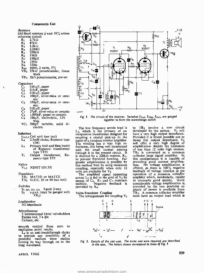
Fig. 1. The circuit of the receiver. Switches Si(a), 51(b), 51(c), are ganged together to form the wavechange switch
The low frequency anode load is L5, which is the primary of an inexpensive transformer designed for coupling a crystal pick -up to the input of a common emitter amplifier. The winding has a very high in- ductance, this being well maintained with the small current passing through it in the present circuit. It is shunted .by a 220kû resistor, R5, to prevent threshold howling. Far greater amplification is possible by this method than by using resistance coupling, especially when only 12 volts are available for V1.
The amplified signal appearing across L5 is fed to the grid of V2 by means of C6. R7 and C7 maintain stability. Negative feedback is provided by R6.
Valve- Transistor Coupling The arrangements for coupling V2
C D
it1
to TR2 involve a new circuit developed by the author. V2 will have a very high output impedance. Provided it is found possible not to damp this output impedance, V2 will offer a very high degree of amplification despite the limitation of less than 12 volts high tension. TR2 is connected as a common collector large signal amplifier. In this configuration it is capable of providing good current amplifica- tion. No voltage amplification is offered, as there is 100% negative feedback of voltage inherent in the operation of a common collector amplifier which, incidentally, results' in unusually good quality. Quite considerable voltage amplification is, provided by the two pentodes so plenty of power is available from TR2. A common collector amplifier must have an output load which is
L1 L2
Sleeve
3/4 -1 I - I/2 --- I° -- = -3/i6
Fig. 2. Details of the coil -unit. The turns and wire required are described in the text. The letters shown correspond to those of Fig. 1
APRIL 1966 539
www.americanradiohistory.com
not too low, to maintain its current amplification and high input im- pedance which, in favourable cir- cumstances, is similar to the output impedance of a pentode. It follows, therefore, that direct coupling from a pentode valve to a common collector transistor power amplifier is both practicable and highly efficient, provided a transistor is chosen which gives satisfactory results with a base current equal to the anode current passed by the pentode.
It will be seen that the input of TR2 forms the output load for V2. This is a most satisfactory load as it has a high impedance to a.c. (the signal) and a low resistance to direct current. A snag, however, remains to be overcome. Although the resistance to d.c. of V2 forms the bias arm from the negative supply line to base, the path from base to the positive line remains open. There is, therefore, a state of affairs which can lead to thermal runaway, and the normal solution of a resistor between base and positive arm is ruled out as it would cause hopeless damping of the load offered to V2. The answer to the problem is to abandon any idea of current stabilisa- tion and adopt, instead, a form of power stabilisation. That is to say, we allow the current passed by TR2 to vary but arrange that any increase in current is accompanied by a corresponding decrease in voltage available, the power remaining sub-
stantially constant and within the limits allowed for the transistor. This effect is produced by R9. C9 is a bypass for the signal.
TR2 must be a high amplification output transistor which will tolerate 100mW and, in order not to be damaged while VR2 is being adjusted, up to 30mA current. The author recommends the G.E.C. S5 or S6.2 For maximum power, bearing in mind the function of R9 and the impedance of the output load, TR2 should pass about IOmA. For this it will require a base current of from about 50 to 150p.A depending on its amplification factor. It is necessary, therefore, for V2 to be set up to pass this current, and the necessary adjustment is made by VR2, which controls grid bias. If a milliammeter is available it should be inserted between T1 and the positive line, and VR2 adjusted so that IOmA is registered. If no milliammeter is available adjustment can be done by ear, using a powerful station and adjusting for maximum volume without distortion. If grid bias is too great, both V2 and TR2 will be short of current and there will be distor- tion. If grid bias is too small a heavy current will pass through TR2 and,
2 The S5 and S6 (or GET.S5 and GET.S6) transistors do not appear in the normal lists, but are available as surplus items at very low cost. The author obtained his from Lasky's Radio, 207 Edgware Road, London, W.2. A possible alternative in the present circuit would be the ACYI8 or ACY21.- EDITOR.
because of R9, it will be short of voltage and again there will be distortion. R9 will prevent damage to TR2 whatever the setting of VR2.
Loudspeaker Requirements It is recommended that a good
loudspeaker be used and that it be mounted in a separate box to avoid any possibility of microphonic howl- ing due to the large amount of audio frequency amplification.
Nothing longer than a normal car aerial should be used. Earthing is automatic through the battery. The receiver should be insulated from the metalwork of the caravan or car and may then be used whether the negative or positive side of the battery is earthed. There is some advantage in using a metal case for the receiver, since this prevents direct pick -up of a very powerful signal by the coil unit. The lead to the aerial should not be screened, since this will reduce input as a result of losses due to self- capacitance which cannot be "tuned out" with an untuned input stage. There is no need for screening, either, with a stationary engine.
The circuit will be found sur- prisingly sensitive. In South Devon, the Home, Light and Third pro - grammes, together with four Con- tinental stations, can be received in daylight at good volume, and about 30 alternative programmes are offered after dark.
CAN ANYONE HELP? Requests for information are inserted in this feature free of charge, subject to space being available. Users of this service undertake to acknowledge all letters, etc., received and to reimburse all reasonable expenses incurred by correspondents. Circuits, manuals, service sheets, etc., lent by readers must be returned in good condition within
a reasonable period of time
EMI Emicorda Model 2031H. -E. G. Priestly, 6 Lynden Avenue, High Busy Lane, Windhill, Shipley, Yorks. -circuit, service manual of this tape recorder, loan or purchase, all expenses met.
Cossor 1035 Oscilloscope. -B. L. Anderson, 6 Hallam Mews, Hallam Street, London, W.1- service manual or circuit diagram. Also circuit for Musi -Pak (U.S.A.) continuous background music playback machine and HMV 2314 transistor stereogram. Each will be photo- copied and returned.
540
Oscilloscope Type 11. -R. E. Fields, 49 Torkington Road, Gatley, Cheadle, Cheshire -circuit or service manual for this ex -Air Ministry equipment (Ref. No. 10s/562).
s t
Coil. -R. K. Lloyd, Lloyd's, P.O. Box 1164, Lusaka, Zambia, Africa -details required for making the Wearite type PA2 coil (unobtainable at location). Also connections and voltages for the klystron type WL -417A.
THE RADIO CONSTRUCTOR
www.americanradiohistory.com
Yorioble Yolloge Regulated Supply
with Excess Current Protection
SUGGESTED CIRCUIT No. 185
D DRING EXPERIMENTAL WORK with transistor circuits it is quite possible for unexpected
results or faulty connections to cause an excessive current to be drawn from the supply. This excessive current may readily damage the power supply as well as the semiconductors in the experimental circuit itself.
At the same time it is desirable to have available, for experimental work, a power supply offering a continuously variable output voltage with reasonably good regulation. Experimental circuits whose be- haviour may be unpredictable may then be fed at first from a low output voltage, this being brought up to the full voltage if initial results are satisfactory. The variable output voltage facility also, of course, allows the selection of any particular working voltage which is required.
This month's "Suggested Circuit" presents a design for a power supply unit which meets all these require- ments. The unit has a variable voltage output with a maximum of about 12 volts, and it offers reason- ably good regulation. What is
perhaps the most important feature is that its output drops to zero if any attempt is made to draw more than a specified maximum current, the specified maximum current being selected by a switch. It is, in fact, impossible to draw more than the selected maximum current from the power unit. As will be seen later, the circuit suffers from the drawback that several high wattage resistors are required, together with a larger mains transformer than would normally be employed to supply the output voltage and current provided. However the writer feels that, for experimental and laboratory work, the disadvantages of slight extra bulk and cost which result from the
APRIL 1966
larger transformer and high wattage resistors are outweighed by the advantages in performance which are provided.
Short- Circuit Protection Before proceeding to the power
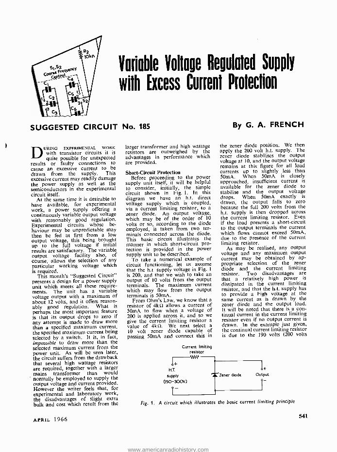
supply unit itself, it will be helpful to consider, initially, the simple circuit shown in Fig. 1. In this diagram we have an h.t. direct voltage supply which is coupled, via a current limiting resistor, to a zener diode. An output voltage, which may be of the order of 10 volts or so, according to the diode employed, is taken from two ter- minals connected across the diode. This basic circuit illustrates the manner in which short -circuit pro- tection is provided in the power supply unit to be described.
To take a numerical example of circuit functioning, let us assume that the h.t. supply voltage in Fig. 1
is 200, and that we wish to take an output of 10 volts from the output terminals. The maximum current which may flow from the output terminals is 50mA.
From Ohm's Law, we know that a resistor of 4kí2 allows a current of 50mA to flow when a voltage of 200 is applied across it, and so we give the current limiting resistor a value of 4kO. We next select a 10 volt zener diode capable of passing 50mA and connect this in
Current limiting resistor
By G. A. FRENCH
the zener diode position. We then apply the 200 volt h.t. supply. The zener diode stabilises the output voltage at 10, and the output voltage remains at this figure for all load currents up to slightly less than 50mA. When 50mA is closely approached, insufficient current is available for the zener diode to stabilise and the output voltage drops. When 50mA exactly is drawn, the output falls to zero because the full 200 volts from the h.t. supply is then dropped across the current limiting resistor. Even if the load presents a short -circuit to the output terminals the current which flows cannot exceed 50mA, due to the presence of the current limiting resistor.
As may be realised, any output voltage and any maximum output current may be obtained by ap- propriate selection of the zener diode and the current limiting resistor. Two disadvantages are that a relatively high power is
dissipated in the current limiting resistor, and that the h.t. supply has to provide a high voltage at the same current as is drawn by the zener diode and the output load. It will be noted that there is a con- tinual current in the current limiting resistor even if no output current is drawn. In the example just given, the continual current limiting resistor is due to the 190 volts (200 volts
HT supply
050-300V)
Fig.Fig. 1. A circuit which illustrates the basic current limiting principle
Zener diode Output
541
www.americanradiohistory.com
SI
AC. mains RI
15kn, 6W
R4
3.6kn,30W
R5
5kn,lOW
R6 40 4 mA
2OmA 80mA R2 S2
2kn,w.w.
TI see. voltage
R I
R 4 R5
5 6
200.0 l2kn 3kn 391(n 9Ikn -200 5W 24W 8W 3W
150 -0 9Ikn 24kn 3kn 6.8kn -150 4W 20W 6W 2W
OAZ 213
(see text)
C2 TRI
+ 100
OC26 NF 15V wkg.
All fixed resistors ± 5% R2 - voltage selector S2 - maximum current selector
+1
Output
-1
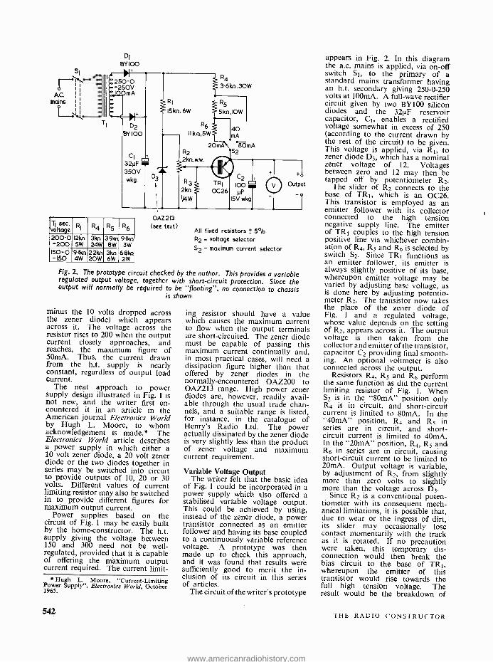
Fig. 2. The prototype circuit checked by the author. This provides a variable regulated output voltage, together with short -circuit protection. Since the output will normally be required to be "floating ", no connection to chassis
is shown
minus the 10 volts dropped across the zener diode) which appears across it. The voltage across the resistor rises to 200 when the output current closely approaches, and reaches, the maximum figure of 50mA. Thus, the current drawn from the h.t. supply is nearly constant, regardless of output load current.
The neat approach to power supply design illustrated in Fig. 1 is not new, and the writer first en- countered it in an article in the American journal Electronics World by Hugh L. Moore, to whom acknowledgement is made. * The Electronics World article describes a power supply in which either a 10 volt zener diode, a 20 volt zener diode or the two diodes together in series may be switched into circuit to provide outputs of 10, 20 or 30 volts. Different values of current limiting resistor may also be switched in to provide different figures for maximum output current.
Power supplies based on the circuit of Fig. 1 may be easily built by the home -constructor. The h.t. supply giving the voltage between 150 and 300 need not be well - regulated, provided that it is capable of offering the maximum output current required. The current limit-
* Hugh L. Moore, "Current- Limiting Power Supply ". Electronics World, October 1965.
ing resistor should have a value which causes the maximum current to flow when the output terminals are short -circuited. The zener diode must be capable of passing this maximum current continually and, in most practical cases, will need a dissipation figure higher than that offered by zener diodes in the normally- encountered OAZ200 to OAZ213 range. High power zener diodes are, however, readily avail- able through the usual trade chan- nels, and a suitable range is listed, for instance, in the catalogue of Henry's Radio Ltd. The power actually dissipated by the zener diode is very slightly less than the product of zener voltage and maximum current requirement.
Variable Voltage Output The writer felt that the basic idea
of Fig. 1 could be incorporated in a power supply which also offered a stabilised variable voltage output. This could be achieved by using, instead of the zener diode, a power transistor connected as an emitter follower and having its base coupled to a continuously variable reference voltage. A prototype was then made up to check this approach, and it was found that results were sufficiently good to merit the in- clusion of its circuit in this series of articles.
The circuit of the writer's prototype
appears in Fig. 2. In this diagram the a.c. mains is applied, via on -off switch St, to the primary of a standard mains transformer having an h.t. secondary giving 250 -0 -250 volts at 100mA. A full -wave rectifier circuit given by two BY100 silicon diodes and the 321,.F reservoir capacitor, C1, enables a rectified voltage somewhat in excess of 250 (according to the current drawn by the rest of the circuit) to be given. This voltage is applied, via RI, to zener diode D3, which has a nominal zener voltage of 12. Voltages between zero and 12 may then be tapped off by potentiometer R2.
The slider of R2 connects to the base of TRt, which is an 0C26. This transistor is employed as an emitter follower with its collector connected to the high tension negative supply line. The emitter of TRt couples to the high tension positive line via whichever combin- ation of R4, R5 and R6 is selected by switch S2. Since TRt functions as an emitter follower, its emitter is always slightly positive of its base, whereupon emitter voltage may be varied by adjusting base voltage, as is done here by adjusting potentio- meter R2. The transistor now takes the place of the zener diode of Fig. 1 and a regulated voltage, whose value depends on the setting of R2, appears across it. The output voltage is then taken from the collector and emitter of the transistor, capacitor C2 providing final smooth- ing. An optional voltmeter is also connected across the output.
Resistors R4, R5 and R6 perform the same function as did the current limiting resistor of Fig. 1. When S2 is in the "80mA" position only R4 is in circuit, and short -circuit current is limited to 80mA. In the "40mA" position, R4 and R5 in series are in circuit, and short - circuit current is limited to 40mA. In the "20mA" position, R4, R5 and R6 in series are in circuit, causing short -circuit current to be limited to 20mA. Output voltage is variable, by adjustment of R2, from slightly more than zero volts to slightly more than the voltage across D3.
Since R2 is a conventional poten- tiometer with its consequent mech- anical limitations, it is possible that, due to wear or the ingress of dirt, its slider may occasionally lose contact momentarily with the track as it is rotated. If no precaution were taken, this temporary dis- connection would then break the bias circuit to the base of TRt, whereupon the emitter of this transistor would rise towards the full high tension voltage. The result would be the breakdown of
542 THE RADIO CONSTRUCTOR
www.americanradiohistory.com
the transistor and the risk of damage to components connected to the output terminals. Resistor R3 per- forms the important task of prevent- ing this eventuality. If any momen- tary disconnection between the slider and track occurs in R2, resia04 R3 still allows sufficient bias current to flow to keep the emitter of TRI at a safe value. The lowest current gain figure quoted for an 0C26 is
O. whereupon a base current of approximately 4mA would allow an emitter current of 80mA to flow. R3 has a value of 2k0, and a base current of 4mA would cause a voltage of 8 to appear across it. Thus, even with S2 set to the "80mA" position and an 0C26 on the bottom gain figure in the TRI position, a momentary disconnection of the slider of R2 could not result in a collector- emitter voltage in excess of about 8. Whilst the presence of R3 prevents damage to TRI, it would still be wise to employ a good -quality component in the R2 position. It should be added that the writer experienced no difficulty in practice with intermittent contact in R2, despite the fact that the component used here had seen a considerable amount of service in other equipment.
The presence of R3 results in a non -linear relationship between out- put voltage and spindle rotation in R2. However, output voltage con- trol is quite smooth and there is no difficulty in adjustment.
Further Points The prototype employed a mains
transformer having a secondary current of 100mA, this component being immediately to hand when the circuit was tried out. Some of the rectified high tension current has to flow through the circuit given by the zener diode and R2, and the available output current becomes reduced in consequence. Bearing in mind the minimum gain figure of 20 for an 0C26, it was considered that at least 5mA should flow through the track of R2. It is also desirable to pass at least several milliamps through the zener diode to bring it well onto the flat part of its curve. The compromise eventually arrived at resulted in the choice of component values shown in Fig. 2. With these values, about 16mA flows through R1, about 12mA passing through R2 and R3 when the slider of R2 is at the top of its track. This left some 84mA available for the emitter of TRI, whereupon the maximum current offered by the power supply unit can be made a nominal 80mA.
The OAZ213 has a spread in
zener voltage of 9.4 to 15.3 at 5mA and it may be desirable to select a diode whose zener voltage is in the region of 12 to 13 volts. The diode employed in the prototype had a zener voltage of approximately 11.5, and this prevented the output voltage from rising to a full 12 volts when the slider of R2 was at the top of its track. If an alternative zener diode is employed its zener voltage should not exceed 14, since higher voltages could bring the 0C26 close to its maximum rated operating conditions.
The values for R4, R5 and R6 were found empirically, as the rectified voltage across C1 has re- latively poor regulation. It is a consequence of this poor regulation that these three resistors do not bear simple numerical ratios with each other, despite the fact that the maximum currents selected by S2
are in the ratio 20 : 40 : 80. It is possible that other mains trans- formers, because of differing internal resistances, may offer slightly dif- ferent voltages across C1. Because of this, R4, R5 and R6 may requite slight adjustment in value. Short - circuit current is measured, incident- ally, by connecting a milliammeter with an appropriate f.s.d. across the output terminals.
It is possible to employ trans- formers having lower voltage secon- daries in the T1 position, and the table in Fig. 2 shows suggested values for R1, R4, R5 and R6 for transformers having secondaries of 200 -0 -200 and 150 -0 -150 volts at 100mA. The values are calculated, and those for R4, R5 and R6 may need adjustment in practice.
The 80mA output current offered by the 100mA transformer in the circuit of Fig. 2 should be adequate for most transistor experimental work. Higher output currents can be given if a transformer having a
12 "(11.6V
II IO Rreg=8n
9 8
Output 7 6V Rreg =106n
voltage
4 3V Rmg = 53n
Rreg=I.3n
higher secondary current rating is employed, the values of R4, R5 and R6 being adjusted accordingly. An alternative method of energising the zener diode and potentiometer is discussed at the end of this article, whereupon the transformer secon- dary current saved can be added to that available at the output. This alternative method of running the zener diode section should also be used if output currents in excess of 120mA are to be employed.
Some constructors may require that S2 select less or more than three maximum currents, or they may require different maximum current figures. The requisite changes to the switch and current limiting resistor values can, of course, be readily visualised.
The 0C26 is well under -run in the present application, but it might still be wise to mount it on a small heat sink. Other power p.n.p. transistors having suitable voltage and current ratings could also be used and improved performance (from the point of view of regulation) would result if the transistor chosen has a gain higher than that offered by the 0C26.
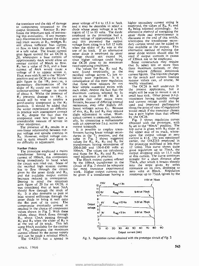
Fig. 3 shows regulation curves obtained with the prototype, with S2 set to the "80mA" position. The top curve is given with R2 slider at the upper end of its track, where- upon the output voltage at zero current is 11.6. (As was mentioned earlier, the OAZ213 employed in the prototype stabilised at less than 12 volts). This curve shows quite good regulation up to 75mA, the output dropping only to 11.5 volts at this current. The curve continues straight for a short distance after 75mA, after which it breaks sharply into the slope given by series resistance on its own, dropping to zero volts at 80mA. Regulation resistance up to 75mA (given by the
11.5V at 75mA
8.4V at 75mA
5.2V at 75mA
2.6V at 75mA
2
0 b 20 30 40 50 60
Output current (mA)
70 BO 90
Fig. 3. Regulation curves obtained with the prototype circuit of Fig. 2
APRIL 1966 543
www.americanradiohistory.com
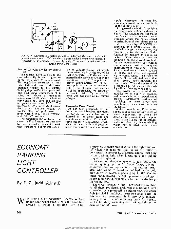
Fig. 4. A suggested alternative method of supplying the zener diode and potentiometer circuit. This enables a higher output current with improved regulation to be achieved. R1 and R2 of Fig. 2 are not required when the
circuit shown here is used
drop of 0.1 volts divided by 75mA) is 1.3(2.
The second curve applies to the case where R2 is set to give an output of 9 volts at zero current. The regulation resistance is, this time, 80; and there is the same dramatic change to the current limiting slope as 80mA is approached. The next curve commences at 6 volts, and shows a regulation resistance of 10.60, whilst the bottom curve starts at 3 volts and exhibits a regulation resistance of 5.3(2. The last two curves also clearly illustrate the current limiting action. A similar class of performance is given when S2 is set to the "40mA" and "20mA" positions.
The regulation shown by all the curves in Fig. 3 should be adequate for most normal experimental work with transistors. The poorer regula-
tion at voltages below that which occurs when R2 is at the top of its track is patently due to the resistance inserted in the base bias circuit by the potentiometer itself. This point was further demonstrated by the fact that ripple on the output terminals (with C2 out of circuit) increased as R2 slider approached the centre of the track. With C2 in circuit, ripple was negligible at all output voltages.
Alternative Zener Circuit As has been described, part of
the current available from the mains transformer secondary has to be diverted to the zener diode and potentiometer section. If the added complication is considered worth- while the zener diode and potentio- meter can be run from an alternative
supply, whereupon the total h.t. secondary current becomes available for the output circuit.
A suggested method of supplying the zener diode section is shown in Fig. 4. This assumes that the mains transformer has two 6.3 volt heater windings which can be connected in series. Four silicon diodes (which could be Lucas type DD000) are connected in a bridge circuit, the rectified voltage being applied, via resistor R7 to the zener diode. Resistor R3 remains in circuit as before. Since there is now no limitation on the current available for the potentiometer this current can be increased, with a consequent improvement in regulation. In Fig. 4 the potentiometer value is reduced to 500(2, and it is re- designated R8 in consequence. The value of resistor R7 is adjusted such that about 10mA flows through the zener diode. When the zener diode is stabilising, the current through R8 will be of the order of 24mA.
The writer has not tried the modification of Fig. 4 in practice, and presents it as an experimental project. Alternative methods of supplying the zener diode and potentiometer may also occur to the reader.
A final point is that, if the power supply unit is built up as a piece of bench equipment, it would be desirable to provide it with a pilot lamp. Such a lamp can be conven- iently run from any heater winding which may be fitted to the mains transformer.
ECONOMY PARKING LIGHT CONTROLLER
By F. C. Judd, A.Inst.E.
WHEN LITTLE BUFF COLOURED TICKETS APPEAR under your windscreen wipers the time has arrived to install a parking light and,
moreover, to make sure it is on at the right time and off when not required. So far as the latter is concerned the answer is, of course, simple: just plug in the parking light when it gets dark and unplug it again at daybreak.
But can you always remember to dash out to the car at lighting up time? If you forget, the buff coloured ticket will appear in stronger terms. And, also, who wants to crawl out of bed in the cold grey dawn to switch a parking light off? On the other hand, leaving the light permanently plugged in for long periods will slowly but surely discharge the car battery.
The circuit shown in Fig. I provides the solution to all these problems, and, whilst a parking light controlled by a photocell is nothing new, the writer feels justified in making at least one small claim for this one, i.e. economy. It is also very reliable, having been in continuous use now for several weeks, faithfully switching the parking light on at dusk and off at dawn.
544 THE RADIO CONSTRUCTOR
www.americanradiohistory.com
PC I
ORP 12 \
12V
6.3v l
O3A or a single
6.3V [12V.03A lamp
O3A
TR2
AIJY 10
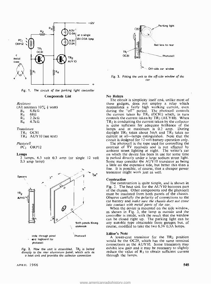
Fig. 1. The circuit of the parking light controller
Components List
Resistors (All resistors 10% * watt)
R1 6.8kû R2 6852 R3 2.2kû R4 4.7kû
Transistors TR1 OC81 TR2 AUY10 (see text)
Photocell PCf ORP12
Lamps 2 lamps, 6.3 volt 0.3 amp (or single 0.3 amp lamp)
Spacers
TR2
N.NIO
TR!
0081
Parking light
Red lens to rear
Photocell
Off -side car window
Fig. 3. Fitting the unit to the off-side window of the car
No Relays The circuit is simplicity itself and, unlike most of
these gadgets, does not employ a relay which necessitates a fairly high working current, even during the "off" period. The photocell controls the current taken by TR1 (0081) which, in turn controls the current taken by TR2 (AUY10). When TR2 is conducting the current taken by the collector is quite sufficient for adequate brilliance of the lamps and at maximum is 0.2 amp. During daylight TR1 takes about 3mA and TR2 takes no current at all -lamps extinguished. Note that the circuit is designed for 12 volt battery operation only.
The photocell is the type used for controlling the contrast of TV receivers and is not affected by ambient street lighting at night. The writer's car on which the device has been in use for some time
12 volt is parked directly under a large sodium street light. Some may consider the AUY10 transistor as being a little on the expensive side, but better this than a fine. It is possible, of course, that a cheaper power
3,e transistor might work just as well.
Hole through panel end tagboard for photocell
Both panels 16s.w.g.
aluminium
Photocell
Fig. 2. How the unit is assembled. TR2 is bolted directly to the rear aluminium panel, which acts as
a heat sink and provides the collector connection
Construction The construction is quite simple, and is shown in
Fig. 2. The heat sink for the AUYIO becomes part of the chassis. Other components and the photocell must be insulated from both panels of the chassis. Observe carefully the polarity of connections to the car battery and make sure the chassis does not come into contact with metal parts of the car.
When the device is mounted on the side window, as shown in Fig. 3, the lamp is outside and the controller is inside, with the result that the window can be closed right up. The parking light can be any suitable type obtainable from garages but, of course, modified to take the two 6.3V 0.3A lamps.
Editor's Note A lower -cost transistor for the TR2 position
would be the 0C29, which has the same terminal connections as the AUY10. Some transistors may exhibit low gain and it may be necessary to slightly reduce the value of R3 to obtain sufficient current through the lamps.
APRIL 1966 545
www.americanradiohistory.com
SINGLE TRANSISTOR
AUDIO OSCILLATOR By J. S. BROWN
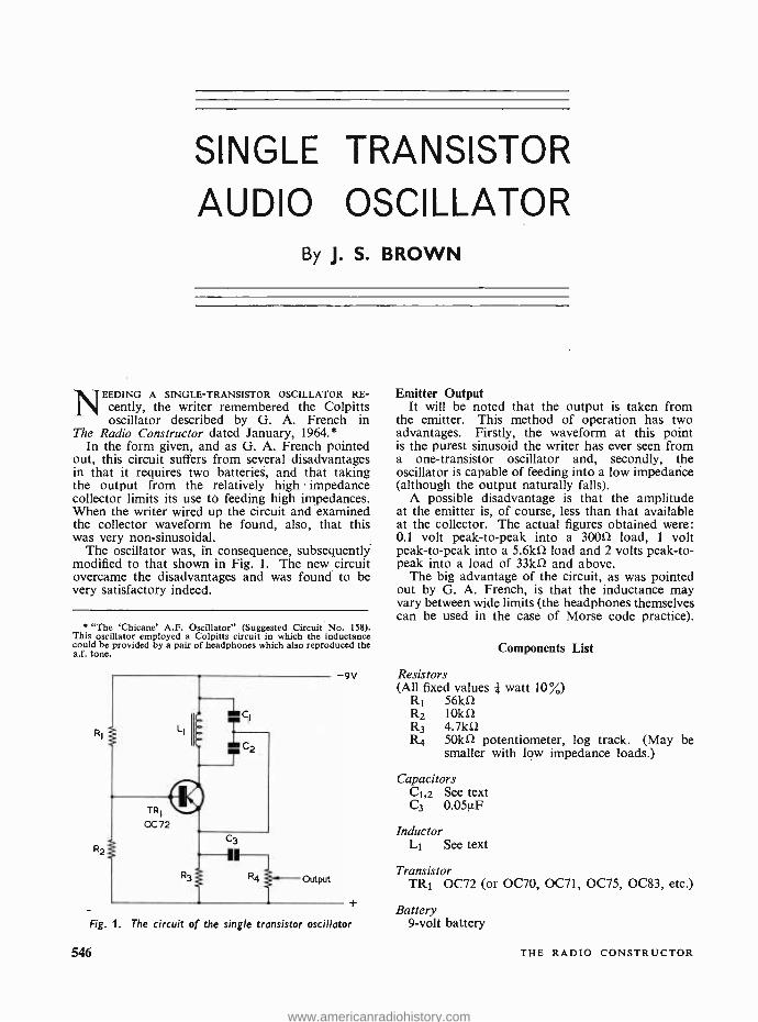
NEEDING A SINGLE -TRANSISTOR OSCILLATOR RE- cently, the writer remembered the Colpitts oscillator described by G. A. French in
The Radio Constructor dated January, 1964.* In the form given, and as G. A. French pointed
out, this circuit suffers from several disadvantages in that it requires two batteries, and that taking the output from the relatively high impedance collector limits its use to feeding high impedances. When the writer wired up the circuit and examined the collector waveform he found, also, that this was very non -sinusoidal.
The oscillator was, in consequence, subsequently modified to that shown in Fig. 1. The new circuit overcame the disadvantages and was found to be very satisfactory indeed.
' "The 'Chicane' A.F. Oscillator" (Suggested Circuit No. 158). This oscillator employed a Colpitts circuit in which the inductance could be provided by a pair of headphones which also reproduced the a.f. tone.
Emitter Output It will be noted that the output is taken from
the emitter. This method of operation has two advantages. Firstly, the waveform at this point is the purest sinusoid the writer has ever seen from a one -transistor oscillator and, secondly, the oscillator is capable of feeding into a low impedance (although the output naturally falls).
A possible disadvantage is that the amplitude at the emitter is, of course, less than that available at the collector. The actual figures obtained were: 0.1 volt peak -to -peak into a 30052 load, 1 volt peak -to -peak into a 5.6k1 load and 2 volts peak -to- peak into a load of 33kû and above.
The big advantage of the circuit, as was pointed out by G. A. French, is that the inductance may vary between wide limits (the headphones themselves can be used in the case of Morse code practice).
Components List
9V Resistors (All fixed values watt 10%)
R1 56kû R2 10kû R3 4.7kû R4 50k0 potentiometer, log track. (May be
smaller with low impedance loads.)
Capacitors C1,2 See text C3 0.05V.F
Fig. 1. The circuit of the single transistor oscillator
546
Inductor L1 See text
Transistor TRI 0072 (or 0070, 0071, 0075, 0083, etc.)
Battery 9 -volt battery
THE RADIO CONSTRUCTOR
www.americanradiohistory.com
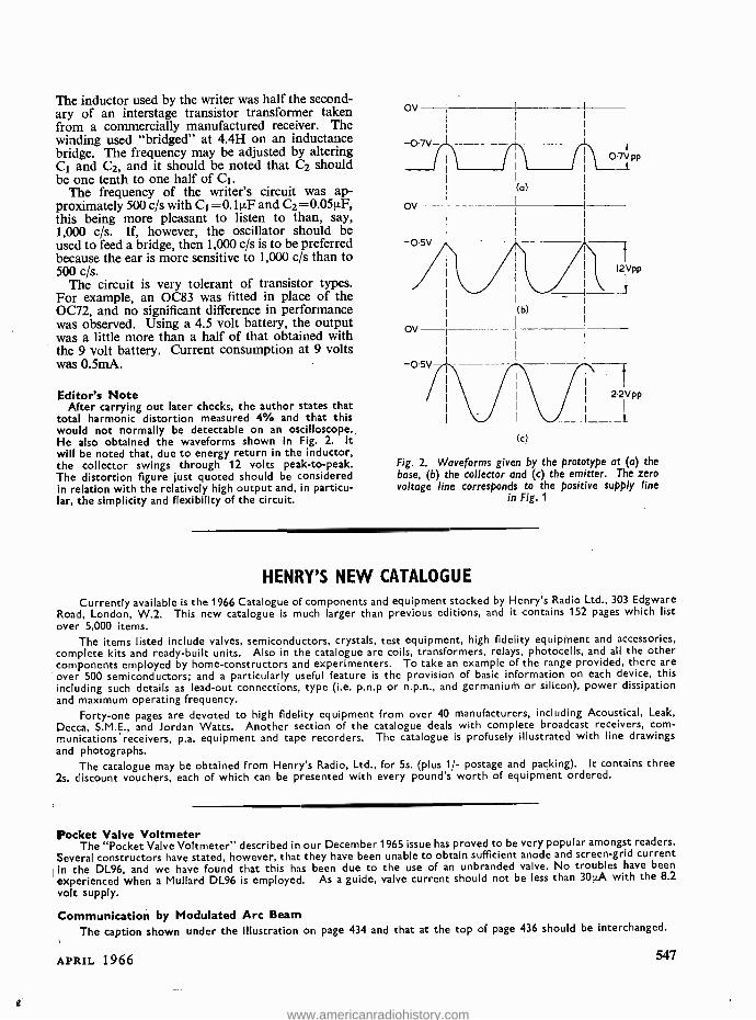
The inductor used by the writer was half the second- ary of an interstage transistor transformer taken from a commercially manufactured receiver. The winding used "bridged" at 4.4H on an inductance bridge. The frequency may be adjusted by altering C1 and C2, and it should be noted that C2 should be one tenth to one half of Ct.
The frequency of the writer's circuit was ap- proximately 500 c/s with C1 =0.1µF and C2 =0.0511F, this being more pleasant to listen to than, say, 1,000 c /s. If, however, the oscillator should be used to feed a bridge, then 1,000 c/s is to be preferred because the ear is more sensitive to 1,000 c/s than to 500 c /s.
The circuit is very tolerant of transistor types. For example, an 0083 was fitted in place of the OC72, and no significant difference in performance was observed. Using a 4.5 volt battery, the output was a little more than a half of that obtained with the 9 volt battery. Current consumption at 9 volts was 0.5mA.
Editor's Note After carrying out later checks, the author states that
total harmonic distortion measured 4% and that this would not normally be detectable on an oscilloscope. He also obtained the waveforms shown in Fig. 2. It will be noted that, due to energy return in the inductor, the collector swings through 12 volts peak -to -peak. The distortion figure just quoted should be considered in relation with the relatively high output and, in particu- lar, the simplicity and flexibility of the circuit.
-0.5V
ov
(a)
(b)
(c)
2'2V pp
Fig. 2. Waveforms given by the prototype at (a) the base, (b) the collector and (c) the emitter. The zero voltage line corresponds to the positive supply line
in Fig. 1
HENRY'S NEW CATALOGUE
Currently available is the 1966 Catalogue of components and equipment stocked by Henry's Radio Ltd., 303 Edgware Road, London, W.2. This new catalogue is much larger than previous editions, and it contains 152 pages which list over 5,000 items.
The items listed include valves, semiconductors, crystals, test equipment, high fidelity equipment and accessories, complete kits and ready -built units. Also in the catalogue are coils, transformers, relays, photocells, and all the other components employed by home -constructors and experimenters. To take an example of the range provided, there are
over 500 semiconductors; and a particularly useful feature is the provision of basic information on each device, this including such details as lead -out connections, type (i.e. p.n.p or n.p.n., and germanium or silicon), power dissipation and maximum operating frequency.
Forty -one pages are devoted to high fidelity equipment from over 40 manufacturers, including Acoustical, Leak,
Decca, S.M.E., and Jordan Watts. Another section of the catalogue deals with complete broadcast receivers, com- munications'receivers, p.a. equipment and tape recorders. The catalogue is profusely illustrated with line drawings and photographs.
The catalogue may be obtained from Henry's Radio, Ltd., for 5s. (plus 1/- postage and packing). It contains three 2s. discount vouchers, each of which can be presented with every pound's worth of equipment ordered.
Pocket Valve Voltmeter The "Pocket Valve Voltmeter" described in our December 1965 issue has proved to be very popular amongst readers.
Several constructors have stated, however, that they have been unable to obtain sufficient anode and screen -grid current in the DL96, and we have found that this has been due to the use of an unbranded valve. No troubles have been
experienced when a Mullard DL96 is employed. As a guide, valve current should not be less than 30p.A with the 8.2
volt supply.
Communication by Modulated Arc Beam
The caption shown under the illustration on page 434 and that at the top of page 436 should be interchanged.
APRIL 1966 547
www.americanradiohistory.com
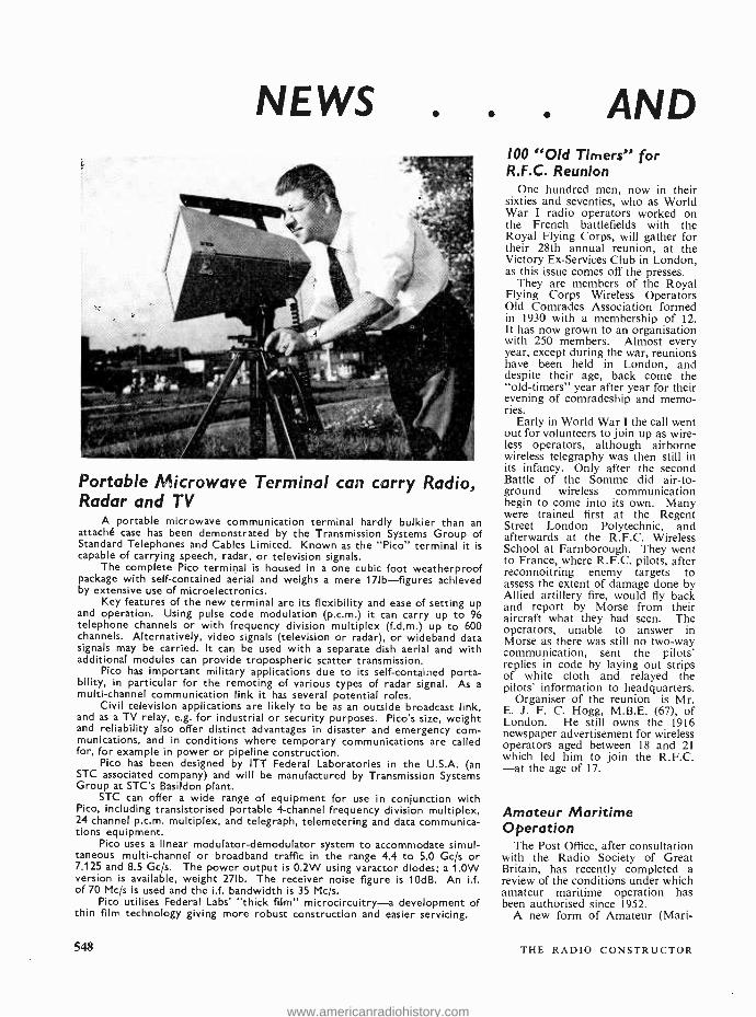
NEWS AND
Portable Microwave Terminal can carry Radio, Radar and TV
A portable microwave communication terminal hardly bulkier than an attaché case has been demonstrated by the Transmission Systems Group of Standard Telephones and Cables Limited. Known as the "Pico" terminal it is capable of carrying speech, radar, or television signals.
The complete Pico terminal is housed in a one cubic foot weatherproof package with self -contained aerial and weighs a mere 171b- figures achieved by extensive use of microelectronics.
Key features of the new terminal are its flexibility and ease of setting up and operation. Using pulse code modulation (p.c.m.) it can carry up to 96 telephone channels or with frequency division multiplex (f.d.m.) up to 600 channels. Alternatively, video signals (television or radar), or wideband data signals may be carried. It can be used with a separate dish aerial and with additional modules can provide tropospheric scatter transmission.
Pico has important military applications due to its self -contained porta- bility, in particular for the remoting of various types of radar signal. As a multi -channel communication link it has several potential roles.
Civil television applications are likely to be as an outside broadcast link, and as a TV relay, e.g. for industrial or security purposes. Pico's size, weight and reliability also offer distinct advantages in disaster and emergency com- munications, and in conditions where temporary communications are called for, for example in power or pipeline construction.
Pico has been designed by ITT Federal Laboratories in the U.S.A. (an STC associated company) and will be manufactured by Transmission Systems Group at STC's Basildon plant.
STC can offer a wide range of equipment for use in conjunction with Pico, including transistorised portable 4- channel frequency division multiplex, 24 channel p.c.m. multiplex, and telegraph, telemetering and data communica- tions equipment.
Pico uses a linear modulator -demodulator system to accommodate simul- taneous multi -channel or broadband traffic in the range 4.4 to 5.0 Gc /s or 7.125 and 8.5 Gc /s. The power output is 0.2W using varactor diodes; a 1.0W version is available, weight 271b. The receiver noise figure is 10dB. An i.f. of 70 Mc /s is used and the i.f. bandwidth is 35 Mc /s.
Pico utilises Federal Labs' "thick film" microcircuitry -a development of thin film technology giving more robust construction and easier servicing.
100 "Old Timers" for R.F.C. Reunion
One hundred men, now in their sixties and seventies, who as World War I radio operators worked on the French battlefields with the Royal Flying Corps, will gather for their 28th annual reunion, at the Victory Ex- Services Club in London, as this issue comes off the presses.
They are members of the Royal Flying Corps Wireless Operators Old Comrades Association formed in 1930 with a membership of 12. It has now grown to an organisation with 250 members. Almost every year, except during the war, reunions have been held in London, and despite their age, back come the "old- timers" year after year for their evening of comradeship and memo- ries.
Early in World War I the call went out for volunteers to join up as wire- less operators, although airborne wireless telegraphy was then still in its infancy. Only after the second Battle of the Somme did air -to- ground wireless communication begin to come into its own. Many were trained first at the Regent Street London Polytechnic, and afterwards at the R.F.C. Wireless School at Farnborough. They went to France, where R.F.C. pilots, after reconnoitring enemy targets to assess the extent of damage done by Allied artillery fire, would fly back and report by Morse from their aircraft what they had seen. The operators, unable to answer in Morse as there was still no two -way communication, sent the pilots' replies in code by laying out strips of white cloth and relayed the pilots' information to headquarters.
Organiser of the reunion is Mr. E. J. F. C. Hogg, M.B.E. (67), of London. He still owns the 1916 newspaper advertisement for wireless operators aged between 18 and 21 which led him to join the R.F.C. -at the age of 17.
Amateur Maritime Operation
The Post Office, after consultation with the Radio Society of Great Britain, has recently completed a review of the conditions under which amateur maritime operation has been authorised since 1952.
A new form of Amateur (Mari-
548 THE RADIO CONSTRUCTOR
www.americanradiohistory.com
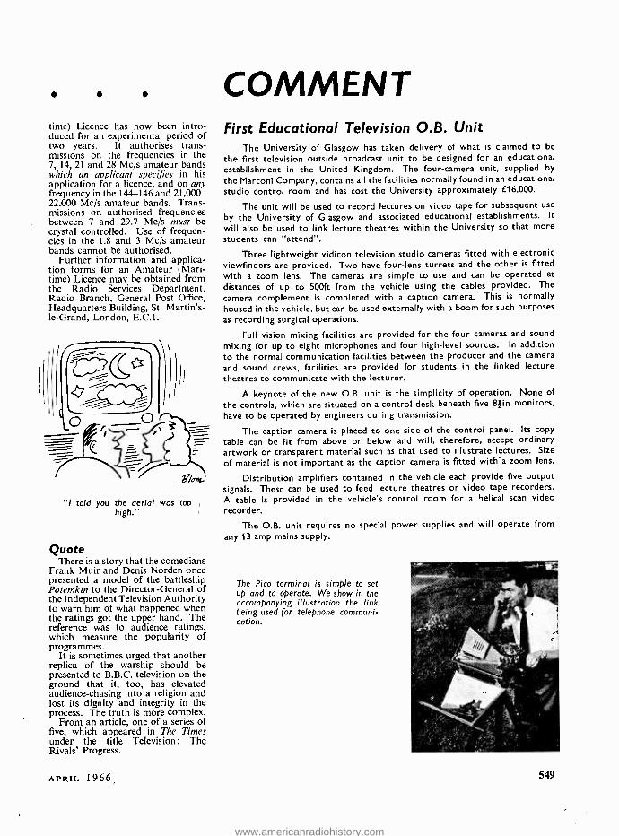
time) Licence has now been intro- duced for an experimental period of two years. It authorises trans- missions on the frequencies in the 7, 14, 21 and 28 Mc /s amateur bands which an applicant specifies in his application for a licence, and on any frequency in the 144 -146 and 21,000- 22,000 Mc /s amateur bands. Trans- missions on authorised frequencies between 7 and 29.7 Mc /s must be crystal controlled. Use of frequen- cies in the 1.8 and 3 Mc /s amateur bands cannot be authorised.
Further information and applica- tion forms for an Amateur (Mari- time) Licence may be obtained from the Radio Services Department, Radio Branch, General Post Office, Headquarters Building, St. Martin's - le- Grand, London, E.C.1.
"I told you the aerial was too high."
Quote There is a story that the comedians
Frank Muir and Denis Norden once presented a model of the battleship Potemkin to the Director -General of the Independent Television Authority to warn him of what happened when the ratings got the upper hand. The reference was to audience ratings, which measure the popularity of programmes.
It is sometimes urged that another replica of the warship should be presented to B.B.C. television on the ground that it, too, has elevated audience -chasing into a religion and lost its dignity and integrity in the process. The truth is more complex.
From an article, one of a series of five, which appeared in The Times under the title Television: The Rivals' Progress.
APRIL 1966
COMMENT First Educational Television 0.8. Unit
The University of Glasgow has taken delivery of what is claimed to be
the first television outside broadcast unit to be designed for an educational establishment in the United Kingdom. The four -camera unit, supplied by
the Marconi Company, contains all the facilities normally found in an educational studio control room and has cost the University approximately £16,000.
The unit will be used to record lectures on video tape for subsequent use
by the University of Glasgow and associated educational establishments. It
will also be used to link lecture theatres within the University so that more students can "attend ".
Three lightweight vidicon television studio cameras fitted with electronic viewfinders are provided. Two have four -lens turrets and the other is fitted with a zoom lens. The cameras are simple to use and can be operated at distances of up to 500ft from the vehicle using the cables provided. The camera complement is completed with a caption camera. This is normally housed in the vehicle, but can be used externally with a boom for such purposes as recording surgical operations.
Full vision mixing facilities are provided for the four cameras and sound mixing for up to eight microphones and four high -level sources. In addition to the normal) communication facilities between the producer and the camera
and sound crews, facilities are provided for students in the linked lecture theatres to communicate with the lecturer.
A keynote of the new O.B. unit is the simplicity of operation. None of
the controls, which are situated on a control desk beneath five 8 -lin monitors, have to be operated by engineers during transmission.
The caption camera is placed to one side of the control panel. Its copy table can be lit from above or below and will, therefore, accept ordinary artwork or transparent material such as that used to illustrate lectures. Size
of material is not important as the caption camera is fitted with'a zoom lens.
Distribution amplifiers contained in the vehicle each provide five output signals. These can be used to feed lecture theatres or video tape recorders. A table is provided in the vehicle's control room for a helical scan video
recorder.
The O.B. unit requires no special power supplies and will operate from any 13 amp mains supply.
The Pico terminal is simple to set up and to operate. We show in the accompanying illustration the link being used for telephone communi- cation.
549
www.americanradiohistory.com
Vacuum or Solid- State?
R. S. Thornton
Our contributor examines the current situation in the tug -of -war between the valve and the
semiconductor
THERE ARE FEW ENGINEERS TODAY WHO WOULD choose to use valves in any application where transistors could be employed. This bald
summary of the present position underlines the remarkable progress in the development of tran- sistors and other semiconductor devices in the last five years. It used to be stated with considerable confidence by valve engineers that vacuum devices would always be predominant in the "four highs ": high temperature, high frequency, high power and high input impedance. These cosy beliefs have all been considerably eroded; indeed the last one has been thoroughly shattered by the arrival of the metal- oxide -semiconductor field effect transistor, mercifully abbreviated to MOSFET.
The valve industry has, however, struck back against the encroachment of semiconductor devices. The rapid development of ceramic -metal sandwich construction has enabled triode and tetrode valves to replace some microwave devices just as transistors are replacing the more conventional valve at lower frequencies. The adoption of the "frame- grid" technique, well known in small transmitting valves, to smaller "receiver" types has prolonged the life span of a class of valve rapidly becoming obsolete.
Let us examine the present position as it exists in each application for active devices.
Domestic Radio And Hi -Fi In domestic radio equipment, the valve is fighting
a losing battle. Transistors dominate entirely the "personal portable" market, are well established in the larger "table radio ", and have a significant foothold in the latest radiograms. The pocket radio owes its existence, of course, to the transistor,
550
the once familiar valve operated portable having been quickly made obsolete by reason of its weight, size and appetite for batteries. The existence of f.m. sound broadcasting prevented the equally rapid replacement of valves in table radios until the price level and performance of high- frequency transistors became commercially and technically attractive. The radiogram market has been the last of the domestic radio group to succumb to the transistor. Though the performance of power transistors has for some time been quite adequate for use in radiograms, the price factor has been marginally prohibitive, especially at the pre- amplifier end where designers were faced with the dilemma of high -impedance, inexpensive crystal pick -ups with at least two transistors to match up to the high impedance, or expensive low - impedance magnetic pick -ups, matching well but requiring more gain. The two answers in sight at the moment are the Mosfet with its high input impedance and, on the other hand, cheaper, mass - produced magnetic pick -ups. The "ultimate" answer may be the amplifier produced recently by an American firm. This uses one single active device, a Mosfet, in an amplifier producing an output of one watt from the input of a crystal pick -up.
The Hi -Fi market is now being very rapidly penetrated by transistors. Whether or not there is a distinctive "transistor sound" is a matter for subjective judgement; objectively, transistors have the usual advantages of small weight, size and heat dissipation, but the most telling point is the use of output stages requiring no output trans- formers. In a market where price is of secondary importance, the lower performance /price ratio for power transistors as compared to valves might be thought irrelevant but, in fact, the difficulty of obtaining the very high standards set by the leading makers of valve amplifiers with currently obtainable power transistors, at an economic price, has delayed the extensive use of transistors by several years. The dyke has now been breached, however, and the flood cannot long be delayed.
Television Television obstinately remains dominated by
the valve, and the principal reason for this is the low price of the line output valve. Although much has been and is being done to reduce the dissipation in this stage, the scanning and e.h.t. requirements of present day wide angle tubes set a. definite limit on the advantages which higher efficiency can bring. Suitable transistors and circuits capable of solving the triple problem of high dissipation, high voltage and rapid switching exist, but not at competitive prices. In addition to this, the use of high -gain frame grid valves in current TV sets has reduced the valve complement to a new mini- mum, creating a very formidable economic barrier for the transistor to conquer.
There are, however, two clouds on this happy valve horizon. One is the mains /battery portable TV set, which now seems to be settling into some-
THE RADIO CONSTRUCTOR
www.americanradiohistory.com
thing more than a passing fashion. . Not only are these small -screen sets taking a large part of the "second -set" market, they enable manufacturers to gain experience of the techniques which will eventually spread to larger sets. The other shock to valve supremacy is the increasing use of transistors in u.h.f. tuners. Very few engineers could have predicted five years ago that transistors would start to replace valves in u.h.f. tuners before they had gained a substantial foothold in other parts of the TV set. The excellent low -noise performance of recent u.h.f. transistors has also led to their increasing use in mast -head pre -amplifiers; the claim has made, in fact, that it is now more rewarding to use a mast -head pre - amplifier than to increase the height or complexity of an aerial array.
The Instrument Industry Passing rapidly over the computer scene, where
even transistors seem to be very much out of date, we see the valve in decline in the instrument industry. In the U.S.A., valves in instruments -apart from such things as gas -filled valves and display devices in counters -seem to be confined mainly to oscilloscopes, and there are signs that this application may soon also vanish as silicon transistors with very high collector voltage ratings become available. Another factor aiding the use of transistors in oscilloscopes is the development of cathode ray tubes using metal meshes to separate the deflection fields from the final accelerating fields. This technique provides very high deflection sensitivity along with the brilliance of trace deman- ded of modern tubes. Even the electrometer valve seems threatened now that the very high impedance Mosfet is available. One of the greatest advantages of transistorised instruments is, of course, battery operation. Anyone who has set up two signal generators, a power pack, and an oscilloscope to test a mixer stage, and has then tripped over the resulting tangle of mains cables will certainly welcome the trend to battery operation.
Industrial Applications In industrial uses, the valve reigns supreme,
although silicon rectifiers have been slowly and quietly replacing valve units for some time now. There is no transistor development on the horizon which seems even remotely likely to replace the valve in r.f. heating equipment. The thyristor, or silicon controlled rectifier, has a long way to go before it can economically replace the larger thyratron and the ignitron. The main industrial objective at the moment for transistors must be instrumentation and control and, indeed, steady progress is being made. There are some signs that transistors will replace valves in the smaller type of ultrasonic cleaner; one interesting pos- sibility is the use of the cleaning medium as a heat sink for the power transistor(s), thus making separate heating unnecessary and enabling higher output powers to be achieved.
APRIL 1966
Communications Equipment As far as communication applications are con-
cerned, the valve and transistor fight on level terms. There is, of course, no dispute at the extreme ends of the power range.
At output powers of one kilowatt and over, valves and other thermionic devices are used almost exclusively. Two trends are noticeable. One is towards the use of valves of ceramic con- struction up to frequencies which, until com- paratively recently, were the province of microwave devices of rather lower power output. The other. trend is towards very high power microwave valves, in the region of several hundreds of kilowatts of c.w. output. High, power` magnetrons have been with us for some time, of course, but these I speak of are generally of the klystron family. This is rather ironical, as the small klystron, so long used as a local oscillator in microwave receivers, is in danger of being replaced by various semi- conductor devices such as tunnel diodes. Much work has been done on "crossed- field" devices, such as the "Amplitron" for very high output powers at microwave frequencies.
At the other end of the scale of power, the transistor is undisputed champion of the field of portable, as distinct from mobile communication. It is indicative of transistor progress that the dividing line can no longer be drawn on a basis of frequency, as was once the case when only the lower frequency portable equipment could be transistor operated. Some of the equipment in this category is of considerable interest, ranging as it does from the multi -channel closed -loop paging systems through the American "Citizen's Band" transceivers to the most highly sophisticated "walkie- talkie" and its television equivalent, the "creepie -peepie
In mobile communications, the battle is still raging. Output powers are higher here, and tran- sistors 'are economically at a disadvantage. The advent of output valves with exceptionally short warm -up times (100 milliseconds is often quoted) has done much to defer any large scale swing over to transistors. Some very recently announced valves feature remarkably high transconductance (over 100mA /V) and, due to the use of frame -grid tech- niques, can pass high currents at low anode voltages.
Heaters And High Voltages The eternal disadvantages of the valve remain
the necessity for heaters and high voltages. The cold cathode valve using tunnel effect in a semi- conductor cathode remains a dream as far as the designer is concerned. High voltage is less of a disadvantage. Modern valves, as stated above, work at low anode voltages. The higher power transistors require fairly high line voltages (50V or more) and if a valve output stage can be operated at 90V there is much to gain financially from using the valve, particularly if the high voltage has to be obtained from a 12V battery via a transistor or (In the higher power range) a thyristor anyway.
551
www.americanradiohistory.com
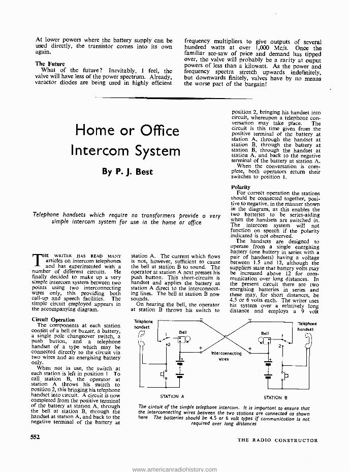
At lower powers where the battery supply can be used directly, the transistor comes into its own again.
The Future What of the future? Inevitably, I feel, the
valve will have less of the power spectrum. Already, varactor diodes are being used in highly efficient
frequency multipliers to give outputs of several hundred watts at over 1,000 Mc /s. Once the familiar see -saw of price and demand has tipped over, the valve will probably be a rarity at ouput powers of less than a kilowatt. As the power and frequency spectra stretch upwards indefinitely, but downwards finitely, valves have by no means the worse part of the bargain!
Home or Office Intercom System
By P. J. Best
Telephone handsets which require no transformers provide a very simple intercom system for use in the home or office
THE WRITER HAS READ MANY articles on intercom telephones and has experimented with a
number of different circuits. He finally decided to make up a very simple intercom system between two points using two interconnecting wires only, this providing both call -up and speech facilities. The simple circuit employed appears in the accompanying diagram.
Circuit Operation The components at each station
consist of a bell or buzzer, a battery, a single pole changeover switch, a push button, and a telephone handset of a type which may be connected directly to the circuit via two wires and an energising battery only.
When not in use, the switch at each station is left in position 1 To call station B, the operator at station A throws his switch to position 2, this bringing his telephone handset into circuit. A circuit is now completed from the positive terminal of the battery at station A, through the bell at station B, through the handset at station A, and back to the negative terminal of the battery at
552
station A. The current which flows is not, however, sufficient to cause the bell at station B to sound. The operator at station A next presses his push button. This short- circuits is handset and applies the battery at station A direct to the interconnect- ing lines. The bell at station B now sounds.
On hearing the bell, the operator at station B throws his switch to
Telephone handset
Bell
2 l_A'
position 2, bringing his handset into circuit, whereupon a telephone con- versation may take place. The circuit is this time given from the positive terminal of the battery at station A, through the handset at station B, through the battery at station B, through the handset at station A, and back to the negative terminal of the battery at station A.
When the conversation is com- plete, both operators return their switches to position 1.
Polarity For correct operation the stations
should be connected together, posi- tive to negative, in the manner shown in the diagram, as this enables the two batteries to be series -aiding when the handsets are switched in. The intercom system will not function on speech if the polarity indicated is not observed.
The handsets are designed to operate from a single energising battery (one battery in series with a pair of handsets) having a voltage between 1.5 and 12, although the suppliers state that battery volts may be increased above 12 for com- munication over long distances. In the present circuit there are two energising batteries in series and these may, for short distances, be 4.5 or 6 volts each. The writer uses his system over a relatively long distance and employs a 9 volt
Telephone handset
Bell
i Interconnecting wires
STATION A STATION B
The circuit of the simple telephone intercom. It is important to ensure that the interconnecting wires between the two stations are connected as shown here, The batteries should be 4.5 or 6 volt types if communication is not
required over long distances
THE RADIO CONSTRUCTOR
www.americanradiohistory.com
battery at each station, this being given by two 4.5 volt bell batteries in series. The constructor should check results with lower voltage batteries before using a voltage higher than 6
at each station. The system may employ a single
interconnecting wire if an "earth" conductor, such as a water pipe, is
available between the two stations. This intercom has many applica-
tions and can, for instance, be fitted between rooms in a house, between house and workshop or garage, or between offices. At the time of writing, the author's system has been
in use for over a year and has given no trouble.
So far as components are con- cerned, the only items which need comment are the handsets. These are intended for two -wire working without transformers and are avail- able from Duke & Co. Ltd., 621
Romford Road, Manor Park, London, E.I2.
Editor's Note It should be mentioned that if,
when both switches are in position 2,
both push buttons are pressed at the same time, the batteries are short - circuited via the interconnecting
wires (whose resistance will limit the short -circuit current which flows). The chance of both buttons being pressed at the same time is slight, and the author states that no problem has occurred on this score with his own system. The risk could, in any case, be avoided by refraining from pushing the button if listening to the handset indicates that the other station is on position 2.
The changeover switch at each
station could, if desired, be incor- porated into a hook for the handset, this switching to position 1 when the handset is hung up.
Recent Publications .
CIRCUITS USING DIRECT CURRENT RELAYS. By A. H. Bruinsma. 86 pages, 82 x 51in. A Philips
Paperback distributed by Iliffe Books Ltd. Price 13s. 6d.
To those who are interested in radio control and robot circuits, A. H. Bruinsma needs no introduction. His present
book commences with general data on d.c. relays and relay operation, then carries on to delayed operation, short -term
operation and operation by light or tape signals. In the last case a tape may have a commentary recorded on one track
and pulses on a second, whereupon the pulses can control the operation of, say, a projector. Later chapters deal with commanded sequence circuits (including bistable and counting circuits), automatic sequence
circuits with commanded start, and oscillating circuits. The final chapter is devoted to miscellaneous circuits, including
one for adding and subtracting. There is a special fascination about the subject of this book, and the reader will find that it contains many ingenious
circuits. The translation from the Dutch is somewhat literal -in Fig. 1 a residual stud is described as a "copper anti -
sticking ridge" -but this will not deter the experimentally- minded reader who is on the search for new ideas and
applications.
TAPE RECORDER SERVICING MANUAL. By H. W. Hellyer. 341 pages, 72 x 10in. Published by George
Newnes Ltd. Price 63s.
Following the pattern set by the Newnes Radio and Television Servicing volumes, this book provides concise
information on tape recorder products under no less than 62 trade names. Service details on tape decks on their own
is given for B.S.R., Collaro, Garrard, Motek, Korting, E.M.I., Thorn and Truvox, and also dealt with is the Gramdeck.
The remainder of the information is for complete tape recorders. A short introductory section on tape recorder servicing precedes the material on manufacturers' products, the
latter taking up almost the whole of the book. The servicing details include all applicable circuit diagrams, and are
compiled from the manufacturers' official data, from trade sources and from bench notes and observations made by the
author as the result of practical servicing experience.
TRANSISTORS WORK LIKE THIS. By Egon Larsen. 62 pages, 6; x 10in. Published by Phoenix House Ltd.
Price 11s. 6d.
Transistors Work Like This is intended for the newcomer, and will be of particular value to any youngster who shows
a budding interest in electronics. But this does not mean that the book is in the "popular science" category -it is
factual and the technical information given, which extends to notes on microcircuits, is sound. An interesting feature
is the historical approach to some of the devices referred to. The author tags dates and names on to many of the
developments described, and also gives a large number of figures to qualify currents, voltages, powers, and the like.
This book could be just what your young nephew needs for his birthday; and it includes, indeed, a short chapter
dealing with careers in transistor electronics.
RADIO SERVICING. Vol. 2- Intermediate Radio Theory. By G. N. Patchett, B.Sc.(Eng.), Ph.D., M.I.E.E.,
M.I.E.R.E., M.I.E.E.E. 160 pages, 52 x 81in. Published by Norman Price (Publishers) Ltd. Price 10s. 6d.
This is a new and enlarged edition of the book, which first appeared in 1956, and it is intended to cover the syllabus
of the intermediate examination in Radio and Television Servicing held by the City and Guilds and the Radio Trades
Examination Board. Valve and transistor circuits are dealt with side by side, and the subjects covered range from transmission and
reception through valve and semiconductor operation and circuits, amplifiers, power supplies and receivers, to the
elements of television. The use of a type which is slightly smaller than usual enables a larger amount of text to appear
than would normally be the case, and makes the book a very economical choice. The author is Head of the Department of Electrical Engineering at Bradford Institute of Technology, and the book
can be thoroughly recommended to students working for the examination just mentioned or for anyone who requires
a good reliable textbook up to this level.
APRII. 1966 553
www.americanradiohistory.com
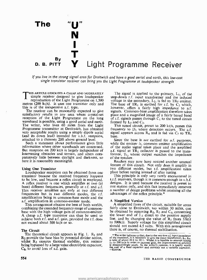
The
By D. B. PITT
N I
T Y Light Programme Receiver
If you live in the strong signal area for Droitwich and have a good aerial and earth, this low -cost single transistor receiver can bring you the Light Programme at loudspeaker strength
THIS ARTICLE DESCRIBES A CHEAP AND MODERATELY simple receiver designed to give loudspeaker reproduction of the Light Programme on 1,500
metres (200 kc /s). It uses one transistor only and this is of the inexpensive a.f. type.
The receiver can be reasonably expected to give satisfactory results in any area where crystal -set reception of the Light Programme on the long waveband is possible, using a good aerial and earth. The writer, who lives 60 miles from the Light Programme transmitter at Droitwich, has obtained very acceptable results using a simple dipole aerial (and its down lead) intended for v.h.f. reception, attached to a chimney 20ft above ground level.
Such a statement about performance gives little information where other wavebands are concerned. But reception on 200 kc /s is largely independent of intervening obstacles and terrain, and alters com- paratively little between daylight and darkness, so here it is reasonably meaningful.
Using One Transistor Loudspeaker reception can be obtained from one
transistor because the received frequency happens to be low, and because a reflex circuit is employed. A reflex receiver is one which amplifies at two (at least) different frequencies, generally at r.f. and a.f. This receiver amplifies not only at two different frequencies but in two different modes, the r.f. amplification being in common -base mode and the a.f. amplification in common- emitter mode.
This arrangement obtains the best of both worlds, combining the extended frequency range of common - base with the high voltage gain of common- emitter. A cheap a.f. type transistor can thus be used to achieve both r.f. and a.f. gain, provided the r.f. does not exceed about 500 kc /s or so.
The Circuit The theoretical circuit appears in Fig. 1. R1 and
R2 provide the base bias by potential divider action, whilst R3 ensures thermal stability, this resistor being bypassed by a large value electrolytic capacitor, C6, to avoid loss of a.f. gain.
554
The signal is applied to the primary, LI, of the step -down r.f. input transformer and the induced voltage in the secondary, L2, is fed to TRI emitter. The base of TRI is earthed for r.f. by C2 which, however, offers a fairly high impedance to a.f. signals. Common -base amplification therefore takes place and a magnified image of a fairly broad band of r.f. signals passes through C1 to the tuned circuit formed by L3 and C3.
This tuned circuit, preset to 200 kc /s, passes this frequency to DI where detection occurs. The a.f. signal appears across R4 and is fed via C5 to TRI base.
Since the base is not earthed for a.f. purposes, while the emitter is, common emitter amplification of the audio signal takes place and the amplified a.f. signal at TRI collector is passed to the trans- former, T1, whose output matches the impedance of the speaker.
Readers may now have noticed another unusual feature of this circuit. Not only does it amplify in two different modes, but r.f. amplification takes place before tuning instead of after tuning.
This principle is only very rarely encountered in t.r.f. receivers, though it is common enough in v.h.f. designs. It is used because the receiver is preset to one station only, and this fact immediately removes a number of design problems whilst retaining all the advantages of the reflex principle.*
A Simplified Version A simplified form of the circuit, suitable for areas
fairly close to Droitwich, say within 30 miles, can be obtained by removing R2, R3 and C6, connecting the lower end of L2 direct to the positive supply line, and by changing the value of R1 from 33kS1 to 100kS2. Supply voltage for this simplified circuit should not exceed 4.5 volts. With this arrangement there is, of course, no thermal stabilisation.
* The writer informs us that, due to the very low r.f. input impedance of the transistor, it is necessary to give the input transformer, LI, L2. a ratio of about 20:1 to 30:1. Whilst it is feasible to attempt tuning L1 to 200 kc /s in order to increase gain, the improvement in practice is disappointingly small. In the writer's opinion, it is hardly worth the cost of a fixed capacitor and certainly not a variable capacitor. -EDITOR.
THE RADIO CONSTRUCTOR
www.americanradiohistory.com
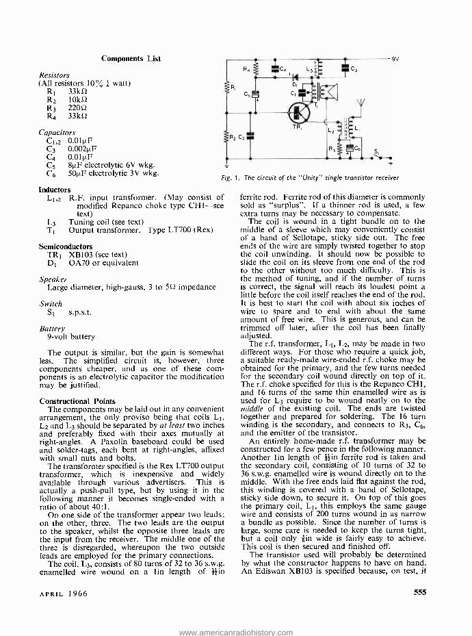
Components List
Resistors (All resistors 10 % watt)
R1 33ko R2 10k52 R3 22052 R4 33k52
Capacitors C1i2 0.01µF C3 0.002µF C4 0.01µF C5 8µF electrolytic 6V wkg. C6 501).F electrolytic 3V wkg.
Fig.
Inductors L1,2 R.F. input transformer. (May consist of
modified Repanco choke type CH 1-see text)
L3 Tuning coil (see text) T1 Output transformer. Type LT700 (Rex)
Semiconductors TR1 XBIO3 (see text) D1 0A70 or equivalent
Speaker Large diameter, high -gauss, 3 to 5Q impedance
Switch Si s.p.s.t.
Battery 9 -volt battery
The output is similar, but the gain is somewhat less. The simplified circuit is, however, three components cheaper, and as one of these com- ponents is an electrolytic capacitor the modification may be justified.
Constructional Points The components may be laid out in any convenient
arrangement, the only proviso being that coils L1, L2 and L3 should be separated by at least two inches and preferably fixed with their axes mutually at right -angles. A Paxolin baseboard could be used and solder -tags, each bent at right- angles, affixed with small nuts and bolts.
The transformer specified is the Rex LT700 output transformer, which is inexpensive and widely available through various advertisers. This is actually a push -pull type, but by using it in the following manner it becomes single -ended with a ratio of about 40:1.
On one side of the transformer appear two leads; on the other, three. The two leads are the output to the speaker, whilst the opposite three leads are the input from the receiver. The middle one of the three is disregarded, whereupon the two outside leads are employed for the primary connections.
The coil, L3, consists of 80 turns of 32 to 36 s.w.g. enamelled wire wound on a lin length of lin
1. The circuit of the "Unity" single transistor receiver
ferrite rod. Ferrite rod of this diameter is commonly sold as "surplus ". If a thinner rod is used, a few extra turns may be necessary to compensate.
The coil is wound in a tight bundle on to the middle of a sleeve which may conveniently consist of a band of Sellotape, sticky side out. The free ends of the wire are simply twisted together to stop the coil unwinding. It should now be possible to slide the coil on its sleeve from one end of the rod to the other without too much difficulty. This is the method of tuning, and if the number of turns is correct, the signal will reach its loudest point a little before the coil itself reaches the end of the rod. It is best to start the coil with about six inches of wire to spare and to end with about the same amount of free wire. This is generous, and can be trimmed off later, after the coil has been finally adjusted.
The r.f. transformer, L1, L2, may be made in two different ways. For those who require a quick job, a suitable ready -made wire -ended r.f. choke may be obtained for the primary, and the few turns needed for the secondary coil wound directly on top of it. The r.f. choke specified for this is the Repanco CHI, and 16 turns of the same thin enamelled wire as is used for L3 require to be wound neatly on to the middle of the existing coil. The ends are twisted together and prepared for soldering. The 16 turn winding is the secondary, and connects to R3, C6, and the emitter of the transistor.
An entirely home -made r.f. transformer may be constructed for a few pence in the following manner. Another lin length of }din ferrite rod is taken and the secondary coil, consisting of 10 turns of 32 to 36 s.w.g. enamelled wire is wound directly on to the middle. With the free ends laid flat against the rod, this winding is covered with a band of Sellotape, sticky side down, to secure it. On top of this goes the primary coil, L1, this employs the same gauge wire and consists of 200 turns wound in as narrow a bundle as possible. Since the number of turns is large, some care is needed to keep the turns tight, but a coil only lin wide is fairly easy to achieve. This coil is then secured and finished off.
The transistor used will probably be determined by what the constructor happens to have on hand. An Ediswan XB103 is specified because, on test, it
APRIL 1966 555
www.americanradiohistory.com
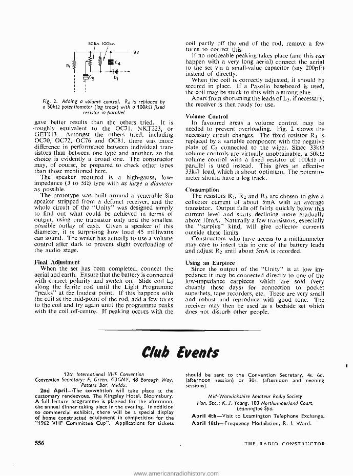
50101. IOOkn
sv
Fig. 2. Adding a volume control. R4 is replaced by a 50kû potentiometer (log track) with a 100kû fixed
resistor in parallel
gave better results than the others tried. It is -roughly equivalent to the 0071, NKT223, or GET113. Amongst the others tried, including 0070, 0072, 0076 and OC81, there was more difference in performance between individual tran- sistors than between one type and another, so the choice is evidently a broad one. The constructor may, of course, be prepared to check other types than those mentioned here.
The speaker required is a high -gauss, low - impedance (3 to 5û) type with as large a diameter as possible.
The prototype was built around a venerable 8in speaker stripped from a defunct receiver, and the whole circuit of the "Unity" was designed simply to find out what could be achieved in terms of output, using one transistor only and the smallest possible outlay of cash. Given a speaker of this diameter, it is surprising how loud 45 milliwatts can sound. The writer has actually to use a volume control after dark to prevent slight overloading of the audio stage.
Final Adjustment When the set has been completed, connect the
aerial and earth. Ensure that the battery is connected with correct polarity and switch on. Slide coil L3 along the ferrite rod until the Light Programme "peaks" at the loudest point. If this happens with the coil at the mid -point of the rod, add a few turns to the coil and try again until the programme peaks with the coil off -centre. If peaking occurs with the
coil partly off the end of the rod, remove a few turns to correct this.
If no noticeable peaking takes place (and this can happen with a very long aerial) connect the aerial to the set via a small -value capacitor (say 200pF) instead of directly.
When the coil is correctly adjusted, it should be secured in place. If a Paxolin baseboard is used, the coil may be stuck to this with a strong glue.
Apart from shortening the leads of L3, if necessary, the receiver is then ready for use.
Volume Control In favoured areas a volume control may be
needed to prevent overloading. Fig. 2 shows the necessary circuit changes. The fixed resistor R4 is replaced by a variable component with the negative plate of C5 connected to the wiper. Since 33kû volume controls are virtually unobtainable, a 50kû volume control with a fixed resistor of 100kû in parallel is used instead. This gives an effective 33kí2 load, which is about optimum. The potentio- meter should have a log track.
Consumption The resistors RI, R2 and R3 are chosen to give a
collector current of about 5mA with an average transistor. Output falls off fairly quickly below this current level and starts declining more gradually above IOmA. Naturally a few transistors, especially the "surplus" kind, will give collector currents outside these limits.
Constructors who have access to a milliammeter may care to insert this in one of the battery leads and adjust R2 until about 5mA is recorded.
Using an Earpiece Since the output of the "Unity" is at low im-
pedance it may be connected directly to one of the low- impedance earpieces which are sold (very cheaply these days) for connection to pocket superhets, tape recorders, etc. These are very small and robust and reproduce with good tone. The receiver may then be used as a bedside set which does not disturb other people.
Club Events 12th International VHF Convention
Convention Secretary: F. Green, G3GMY, 48 Borough Way, Potters Bar, Middx.
2nd April -The convention will take place at the customary rendezvous, The Kingsley Hotel, Bloomsbury. A full lecture programme is planned for the afternoon, the annual dinner taking place in the evening. In addition to commercial exhibits, there will be a special display of home constructed equipment in competition for the "1962 VHF Committee Cup ". Applications for tickets
556
should be sent to the Convention Secretary, 4s. 6d. (afternoon session) or 30s. (afternoon and evening sessions).
Mid - Warwickshire Amateur Radio Society Hon. Sec.: K. 1. Young, 180 Northumberland Court,
Leamington Spa.
April 4th -Visit to Leamington Telephone Exchange.
April 18th -Frequency Modulation, R. J. Ward.
THE RADIO CONSTRUCTOR
www.americanradiohistory.com
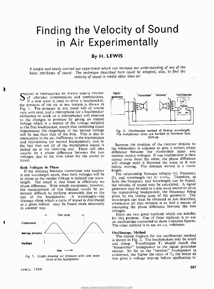
Finding the Velocity of Sound in Air Experimentally
By H. LEWIS
A simple and easily carried out experiment which can increase our understanding of one of the
basic attributes of sound. The technique described here could be adapted, also, to find the
velocity of sound in media other than air
S OUND IS PROPAGATED BY WAVES WHICH CONSIST
of alternate compressions and rarefractions. If a sine wave is used to drive a loudspeaker,
the pressure of the air at any instant is shown in Fig. 1. The pressure at any point will of course vary with time, and a microphone (or a loudspeaker connected to work as a microphone) will respond to the changes in pressure by giving an output voltage which is a replica of the voltage supplied to the first loudspeaker, except that (assuming equal impedances) the magnitude of the second voltage will be less than that of the first. This is due to attenuation in the air, inefficiency in the loudspeaker and microphone (or second loudspeaker), and to the fact that not all of the transmitted sound is picked up at the receiving end. There will also usually be a phase difference between the two voltages, due to the time taken for the sound to travel.
Both Voltages in Phase If the distance between transmitter and receiver
is one wavelength apart, then both voltages will be in phase as the output voltage is delayed one wave- length. The result is that there is effectively no phase difference. With simple equipment, however, the measurement of this distance would be ex- tremely difficult to perform accurately due to the size of the loudspeaker. A wavelength -the distance along which a cycle of sound is distributed at a given instant -may be found more accurately in another way.
Compressed
herogc pressure
Raritled
One cycle
time
Fig. 1. Graph showing air pressure with sine wave drive to the loudspeaker
Signal
generator Transmitter Receiver'
Ti T2
Oscilloscope
Fig. 2. Oscilloscope method of finding wavelength. The transformer cores are earthed to minimise hum
pick -up
Suppose the position of the receiver relative to the transmitter is adjusted to give a certain phase difference between the transmitter input and receiver output voltages. If one loudspeaker is then moved away from the other, the phase difference will change until it becomes the same as it was before moving. The distance moved is a wave- length.
The relationship between velocity (v), frequency (f), and wavelength (w) is: v =fw. Therefore, as both the frequency and wavelength can be found, the velocity of sound may be calculated. A signal generator may be used as a sine wave source to drive the transmitting loudspeaker, the frequency being given by the tuning scale of the generator. The wavelength can then be obtained as just described, whereupon all that remains is to find a means of measuring the phase difference between the two voltages.
There are two good methods which are suitable for this purpose. One of these methods is to use an oscilloscope connected to show Lissajous figures. The other method is to use an a.c. voltmeter.
Oscilloscope Method The circuit diagram for the oscilloscope method
is shown in Fig. 2. The loudspeakers may be small and cheap. Transformer T1 should match the "transmitter" loudspeaker to the signal generator output. So far as the "receiver" loudspeaker is concerned, the higher the ratio of T2 the better as
this gives a voltage step -up before application to
APRIL 1966 557
www.americanradiohistory.com
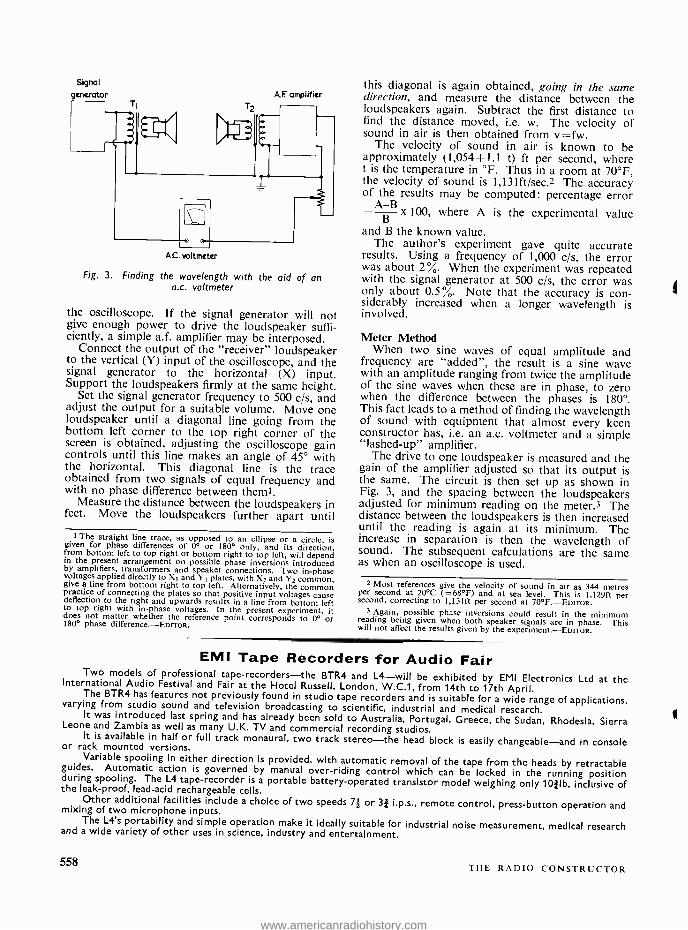
Signal
generator A F amplifier
e
AC voltmeter
Fig. 3. Finding the wavelength with the aid of an a.c. voltmeter
the oscilloscope. If the signal generator will not give enough power to drive the loudspeaker suffi- ciently, a simple a.f. amplifier may be interposed.
Connect the output of the "receiver" loudspeaker to the vertical (Y) input of the oscilloscope, and the signal generator to the horizontal (X) input. Support the loudspeakers firmly at the same height.
Set the signal generator frequency to 500 c /s, and adjust the output for a suitable volume. Move one loudspeaker until a diagonal line going from the bottom left corner to the top right corner of the screen is obtained, adjusting the oscilloscope gain controls until this line makes an angle of 45° with the horizontal. This diagonal line is the trace obtained from two signals of equal frequency and with no phase difference between them'.
Measure the distance between the loudspeakers in feet. Move the loudspeakers further apart until
t The straight line trace, as opposed to an ellipse or a circle, is given for phase differences of 0° or 180° only, and its direction, from bottom left to top right or bottom right to top left, will depend in the present arrangement on possible phase inversions introduced by amplifiers, transformers and speaker connections. Two in -phase voltages applied directly to X1 and Y1 plates, with X2 and Y2 common, give a line from bottom right to top left. Alternatively, the common practice of connecting the plates so that positive input voltages cause deflection to the right and upwards results in a line from bottom left to top right with in -phase voltages. In the present experiment, it does not matter whether the reference point corresponds to 0° or 180° phase difference. -Eorroa.
this diagonal is again obtained, going in the same direction, and measure the distance between the loudspeakers again. Subtract the first distance to find the distance moved, i.e. w. The velocity of sound in air is then obtained from v =fw.
The velocity of sound in air is known to be approximately (1,054 +1.1 t) ft per second, where t is the temperature in °F. Thus in a room at 70 °F, the velocity of sound is 1, 131 ft /sec.2 The accuracy of the results may be computed: percentage error =A_ -B
x 100, where A is the experimental value
and B the known value. The author's experiment gave quite accurate
results. Using a frequency of 1,000 c /s, the error was about 2%. When the experiment was repeated with the signal generator at 500 c /s, the error was only about 0.5%. Note that the accuracy is con- siderably increased when a longer wavelength is involved.
Meter Method When two sine waves of equal amplitude and
frequency are "added ", the result is a sine wave with an amplitude ranging from twice the amplitude of the sine waves when these are in phase, to zero when the difference between the phases is 180 °. This fact leads to a method of finding the wavelength of sound with equipment that almost every keen constructor has, i.e. an a.c. voltmeter and a simple "lashed -up" amplifier.
The drive to one loudspeaker is measured and the gain of the amplifier adjusted so that its output is the same. The circuit is then set up as shown in Fig. 3, and the spacing between the loudspeakers adjusted for minimum reading on the meter.3 The distance between the loudspeakers is then increased until the reading is again at its minimum. The increase in separation is then the wavelength of sound. The subsequent calculations are the same as when an oscilloscope is used.
2 Most references give the velocity of sound in air as 344 metres per second at 20 °C ( =68 °F) and at sea level. This is I,129ft per second, correcting to 1,13Ift per second at 70 °F.- Eotroa. 3 Again, possible phase inversions could result in the minimum reading being given when both speaker signals are in phase. This
will not affect the results given by the experiment.- Fotroa.
EMI Tape Recorders for Audio Fair Two models of professional tape- recorders -the BTR4 and L4 -will be exhibited by EMI Electronics Ltd at the International Audio Festival and Fair at the Hotel Russell, London, W.C.1, from 14th to 17th April. The BTR4 has features not previously found in studio tape recorders and is suitable for a wide range of applications, varying from studio sound and television broadcasting to scientific, industrial and medical research. It was introduced last spring and has already been sold to Australia, Portugal, Greece, the Sudan, Rhodesia, Sierra Leone and Zambia as well as many U.K. TV and commercial recording studios. It is available in half or full track monaural, two track stereo -the head block is easily changeable -and in console or rack mounted versions. Variable spooling in either direction is provided, with automatic removal of the tape from the heads by retractable guides. Automatic action is governed by manual over -riding control which can be locked in the running position during spooling. The L4 tape- recorder is a portable battery- operated transistor model weighing only 10/Ib, inclusive of the leak- proof, lead -acid rechargeable cells. Other additional facilities include a choice of two speeds 71 or 31 i.p.s., remote control, press- button operation and mixing of two microphone inputs. The L4's portability and simple operation make it ideally suitable for industrial noise measurement, medical research and a wide variety of other uses in science, industry and entertainment.
558 THE RADIO CONSTRUCTOR
www.americanradiohistory.com
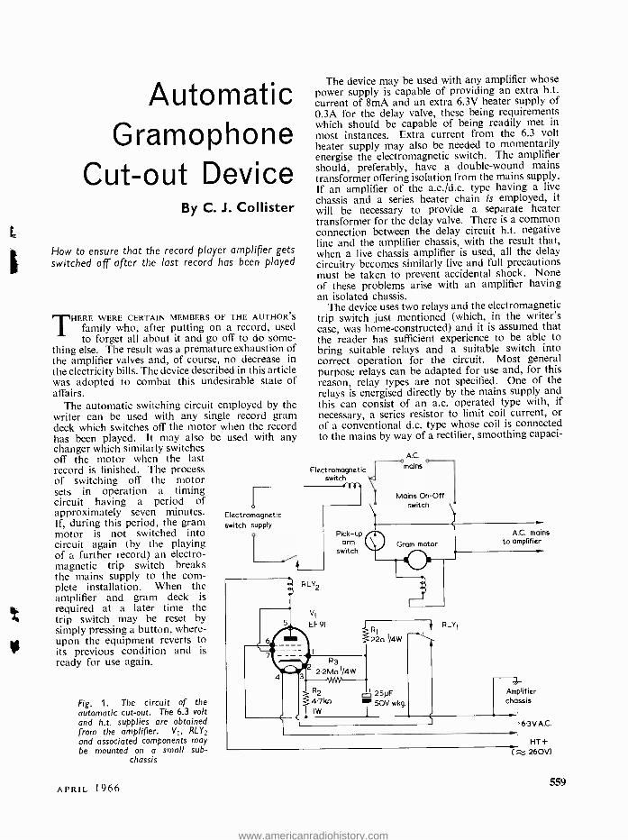
a
Automatic Gramophone
Cut -out Device By C. J. Collister
How to ensure that the record player amplifier gets switched off after the last record has been played
THERE WERE CERTAIN MEMBERS OF THE AUTHOR'S
family who, after putting on a record, used to forget all about it and go off to do some-
thing else. The result was a premature exhaustion of the amplifier valves and, of course, no decrease in the electricity bills. The device described in this article was adopted to combat this undesirable state of affairs.
The automatic switching circuit employed by the writer can be used with any single record gram deck which switches off the motor when the record has been played. It may also be used with any changer which similarly switches off the motor when the last record is finished. The process of switching off the motor sets in operation a timing circuit having a period of approximately seven minutes. If, during this period, the gram motor is not switched into circuit again (by the playing of a further record) an electro- magnetic trip switch breaks the mains supply to the com- plete installation. When the amplifier and gram deck is required at a later time the trip switch may be reset by simply pressing a button, where- upon the equipment reverts to its previous condition and is ready for use again.
Fig. 1. The circuit of the automatic cut -out. The 6.3 volt and h.t. supplies are obtained from the amplifier. VI, RLY2
and associated components may be mounted on a small sub -
chassis
APRIL 1966
The device may be used with any amplifier whose power supply is capable of providing an extra h.t. current of 8mA and an extra 6.3V heater supply of 0.3A for the delay valve, these being requirements which should be capable of being readily met in most instances. Extra current from the 6.3 volt heater supply may also be needed to momentarily energise the electromagnetic switch. The amplifier should, preferably, have a double -wound mains transformer offering isolation from the mains supply. If an amplifier of the a.c. /d.c. type having a live chassis and a series heater chain is employed, it will be necessary to provide a separate heater transformer for the delay valve. There is a common connection between the delay circuit h.t. negative line and the amplifier chassis, with the result that, when a live chassis amplifier is used, all the delay circuitry becomes similarly live and full precautions must be taken to prevent accidental shock. None of these problems arise with an amplifier having an isolated chassis.
The device uses two relays and the electromagnetic trip switch just mentioned (which, in the writer's case, was home -constructed) and it is assumed that the reader has sufficient experience to be able to bring suitable relays and a suitable switch into correct operation for the circuit. Most general purpose relays can be adapted for use and, for this reason, relay types are not specified. One of the relays is energised directly by the mains supply and this can consist of an a.c. operated type with, if necessary, a series resistor to limit coil current, or of a conventional d.c. type whose coil is connected to the mains by way of a rectifier, smoothing capaci-
Electromagnetic switch
Electromagnetic switch supply
RLY2
VI
EF91
Pick -up arm
switch
A.C.
mains o
Mains On -Off switch
Gram motor
A.C. mains to amplifier
R3
24Mn I/4W
R2
47 kn
I
RI
22n I/4W
25pF T50V wkg.
RLYI
Amplifier chassis
63VA.C.
HT+ ( ti 260V)
559
www.americanradiohistory.com
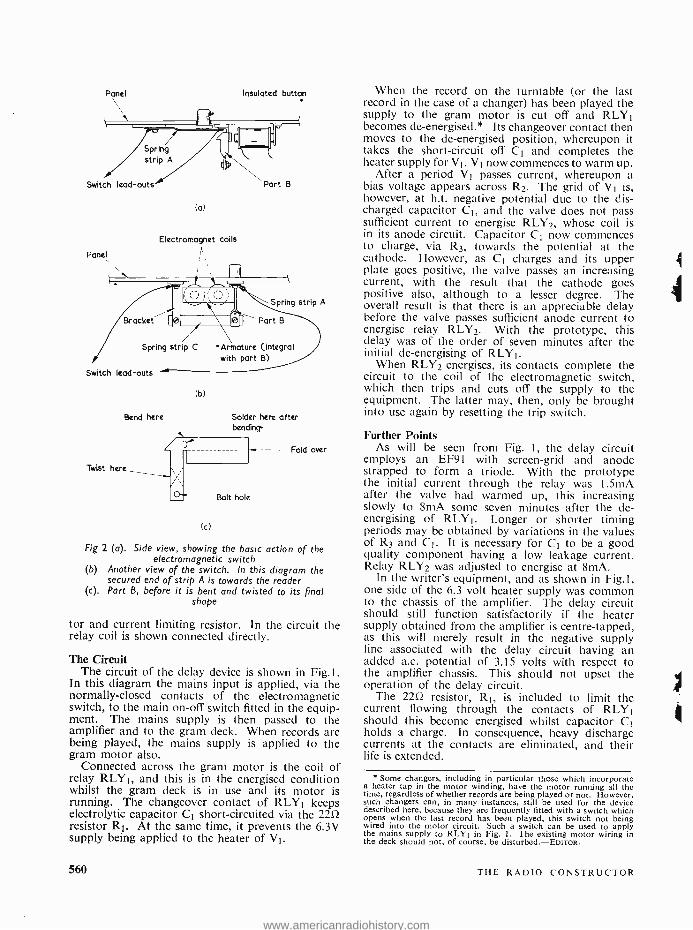
Panel Insulated button
Spring strip A
Switch lead-outs
Panel
(a)
Electromagnet coils
Part B
Spring strip A
Bracket
Spring strip C
Switch lead -outs
Bend here
Twist here
(b)
Solder here after bending
(c)
Bolt hole
Fold over
Fig 2 (a). Side view, showing the basic action of the electromagnetic switch
(b) Another view of the switch. In this diagram the secured end of strip A is towards the reader
(c). Part B, before it is bent and twisted to its final shape
tor and current limiting resistor. In the circuit the relay coil is shown connected directly.
The Circuit The circuit of the delay device is shown in Fig.l.
In this diagram the mains input is applied, via the normally -closed contacts of the electromagnetic switch, to the main on -off switch fitted in the equip- ment. The mains supply is then passed to the amplifier and to the gram deck. When records are being played, the mains supply is applied to the gram motor also.
Connected across the gram motor is the coil of relay RLYI, and this is in the energised condition whilst the gram deck is in use and its motor is running. The changeover contact of RLY1 keeps electrolytic capacitor C1 short -circuited via the 2252 resistor R1. At the same time, it prevents the 6.3V supply being applied to the heater of VI.
560
When the record on the turntable (or the last record in the case of a changer) has been played the supply to the gram motor is cut off and RLY1 becomes de- energised.* Its changeover contact then moves to the de- energised position, whereupon it takes the short -circuit off C1 and completes the heater supply for VI. VI now commences to warm up.
After a period VI passes current, whereupon a bias voltage appears across R2. The grid of V1 is, however, at h.t. negative potential due to the dis- charged capacitor C1, and the valve does not pass sufficient current to energise RLY2, whose coil is in its anode circuit. Capacitor C1 now commences to charge, via R3, towards the potential at the cathode. However, as C1 charges and its upper plate goes positive, the valve passes an increasing current, with the result that the cathode goes positive also, although to a lesser degree. The overall result is that there is an appreciable delay before the valve passes sufficient anode current to energise relay RLY2. With the prototype, this delay was of the order of seven minutes after the initial de- energising of RLYI.
When RLY2 energises, its contacts complete the circuit to the coil of the electromagnetic switch, which then trips and cuts off the supply to the equipment. The latter may, then, only be brought into use again by resetting the trip switch.
Further Points As will be seen from Fig. 1, the delay circuit
employs an EF91 with screen -grid and anode strapped to form a triode. With the prototype the initial current through the relay was 1.5mA after the valve had warmed up, this increasing slowly to 8mA some seven minutes after the de- energising of RLYI. Longer or shorter timing periods may be obtained by variations in the values of R3 and CI. It is necessary for C1 to be a good quality component having a low leakage current. Relay RLY2 was adjusted to energise at 8mA.
In the writer's equipment, and as shown in Fig.l, one side of the 6.3 volt heater supply was common to the chassis of the amplifier. The delay circuit should still function satisfactorily if the heater supply obtained from the amplifier is centre -tapped, as this will merely result in the negative supply line associated with the delay circuit having an added a.c. potential of 3.15 volts with respect to the amplifier chassis. This should not upset the operation of the delay circuit.
The 2212 resistor, RI, is included to limit the current flowing through the contacts of RLY1 should this become energised whilst capacitor C1 holds a charge. In consequence, heavy discharge currents at the contacts are eliminated, and their life is extended.
Some changers, including in particular those which incorporate a heater tap in the motor winding, have the motor running all the time, regardless of whether records are being played or not. However, such changers can, in many instances, still be used for the device described here, because they are frequently fitted with a switch which opens when the last record has been played, this switch not being wired into the motor circuit. Such a switch can be used to apply the mains supply to RLY1 in Fig. I. The existing motor wiring in the deck should not, of course, be disturbed. -EDITOR.
THE RADIO CONSTRUCTOR
4
www.americanradiohistory.com
Electromagnetic Switch The electromagnetic switch has a trip action, and
a suitable ready -made component could be of the type found in model railway transformers whose function is to minimise the risk of burn -out through overloading. However, the author's switch was home -constructed, and it was made up in the manner shown in Figs. 2(a) and (b).
The method of operation is quite simple. Under normal conditions, spring strip A is pressed down, whereupon its free end latches under the projection of part B. The lower end of part B is mounted on spring strip C, which provides slight forward pressure. When strip A is depressed a circuit is completed by way of the three parts, A, B, and C. If a current is applied to the electromagnet winding, part B is attracted to its core, strip A releases, and the circuit is broken. The switch may be restored to its previous condition by pressing the insulated button, whereupon strip A once more latches under the projection on part B.
As may be seen from the view in Fig. 2(b) the electromagnet employs two coils, and these appear in the familiar horseshoe magnet assembly as- sociated with electric bells. Indeed, a very efficient electromagnet may be provided by removing the coils from an electric bell. In the writer's model the electromagnet was provided by winding some 200 turns of 28 s.w.g. enamelled wire on each leg of a large sawn -off iron staple. Care should be taken to connect the two coils such that opposite magnetic poles appear at the core ends presented to part B. The writer's electromagnet was powered by 6.3 volts a.c. taken from the heater supply of the
amplifier. The current drawn by the electromagnet coil was not measured as it flows only for the very short period of time needed to operate the switch, and it was felt that this momentary flow of current would not cause any serious overload of the trans- former.
The spring strips were made from suitably trimmed razor blades, filed as required to expose the actual metal, and provided with notches at the ends to take mounting bolts.
Part B was made from 20 s.w.g. tinplate. This was cut out to the shape shown in Fig .2(c), after which it was bent and twisted to the appearance given in Figs. 2(a) and (b). It will be seen that the folded -over section of part B forms an "armature" consisting of two thicknesses of tinplate, which is attracted to the electromagnet.
The gauge of tinplate employed provides adequate strength, but it is advisable to give added rigidity by applying a blob of solder to the inside of the 90° bend where the "armature" section joins the remainder of part B.
If a switch of this nature is employed, and is run from the heater supply of the amplifier, it is important to ensure that it is completely reliable in operation. Should it not release immediately, a heavy current may be continuously drawn from the amplifier heater supply, with a consequent risk of damage. It is also essential, of course, to ensure that all parts and mounting bolts, etc., which are at mains supply potential are completely insulated so as to obviate the risk of shock to people using the equipment.
Solid State Microwave Oscillators
IN SATELLITE RESEARCH AND CERTAIN OTHER
fields there is a great need for light- weight solid state oscillators which can be used at microwave
frequencies. At the moment klystrons and travelling wave tubes are usually used, but these tubes together with their power supplies tend to be quite heavy by modern standards. The solid state oscillators which have already been produced experimentally can provide a maximum output power of some milli- watts at frequencies up to about 1 Gc /s (1,000 Mc /s). The volume of one of these devices is only about one hundredth of a cubic centimetre.
One type of device being investigated by Standard Telephones and Cables Ltd. at Harlow employs
the Gunn effect (discovered by J. B. Gunn in 1963) in which an electric field applied to low resistivity gallium arsenide causes the charge carriers in the material to travel in regions known as domains. In these devices a layer of gallium arsenide about 15 microns in thickness is deposited on a high resistivity gallium arsenide substrate. An expitaxial construction is used, since this enables heat to be removed from the device at a satisfactory rate. The devices can be used as oscillators, amplifiers and in pulse circuits. It is expected that the maximum power obtainable from this type of device will he raised as research and development proceeds.
APRIL 1966 561
www.americanradiohistory.com
In
Y o u
r
Wo r ks
ho P
562
As readers may be aware, events tend to get a little hectic in the Workshop on occasion. Such a situation occurs at the start of this month's episode, but things soon calm down under the soothing influence of tea, together with a discourse by Smithy the Service- man, for the benefit of his able assistant Dick, on the basic circuits employed in domestic valve tape recorders.
THIS! HEAR THIs!" Smithy groaned inwardly
as he once more attempted to concentrate on the faulty television receiver on his bench.
"Testing, testing!" The Serviceman glanced down at
his watch. One comforting thought broke through the gloom: it was very nearly tea -break.
"One, two, three, four. One, two, three, four!"
It had been a difficult morning. His assistant's first job had been the repair of a record player which tended to go into occasional in- stability at high volume levels, whereupon Dick had enthusiastically proceeded to test it at full volume with the Rolling Stones' latest l.p. After a nerve -wracking quarter of an hour Smithy had, reluctantly, to privately admit the wisdom of Dick's choice of disc when one truly shattering bass guitar chord caused the fault to unexpectedly come on. The occasionally microphonic valve which was giving the trouble suddenly produced a tortured acoustic howl having such undertones of wretched- ness and misery that even the clattering of Dick's screwdriver handle against his bench in time to the lunging rhythm was momentarily stilled. The stricken valve slowly faded into its final demise and blessed peace descended upon the Workshop, but only for the period needed by Dick to find a replacement and plug it into the player. He then checked the new valve, again at full volume, with the other side of the Rolling Stones' l.p.
Optimistically, Smithy had hoped that the next job chosen by his assistant, a somewhat elderly mains table radio, would result in an ambient noise level which was at least several decibels below the threshold of pain. Unfortunately,
his expectations were quickly shattered when Dick found that the primary of the mains transformer in the receiver had burnt out, and that the only suitable replacement avail- able had different mounting centres. Admittedly, there was a brief respite whilst Dick, wearing a direful scowl indicative of intense concentration, marked out and centre -popped the four new holes required; but this was quickly followed by the selection of a No. 10 2BA clearance drill from Dick's stock, the purposeful plugging in of the Workshop electric drill, and the scream of riven metal as the bit battled manfully against the solid mild steel of the receiver chassis. A subsequent brief cessation of labour must be recorded, this taking place at the start of the third hole when Dick, vigorously sucking a finger, retired to the First Aid box. The proceedings were, however, soon resumed with the injured member heavily covered with Elastoplast. A student of cause and effect could find an intriguing chain of circum- stances here: samples of Dick's blood were distributed all round the neighbourhood in the cabinets of radio and television receivers on whose chassis he had carried out drilling operations; these samples were due, in their turn, to the fact that Dick's habitual approach to- wards drilling consisted of applying maximum pressure to the work; this approach was virtually a conditioned reflex which, in its turn, derived from the fact that all Dick's drills were extremely blunt.
The Last Straw A mortal purgatory cannot exist
for ever and the long- suffering Serviceman noted with relief the eventual transfer of the receiver, with its new mains transformer safely installed, to the "Repaired" racks. He had observed that Dick's next choice was a fairly large valve tape recorder of the domestic category and, once more optimistically, he had hoped that this repair would be a little less distressing for the nerves than the previous two had been. Indeed, the affairs of the Workshop had proceeded more or less normally for a time as Dick probed inside the recorder. Glad of the respite, Smithy had filled and switched on the Workshop kettle for the morn- ing's tea -break. He had, in fact, become almost completely immersed in the repair of the television receiver on his bench when Dick's voice, applied to the tape recorder micro- phone, broke into his thoughts.
By now Dick had completed his test recording. He stopped the machine, ran the tape back, made a
THE RADIO CONSTRUCTOR
www.americanradiohistory.com
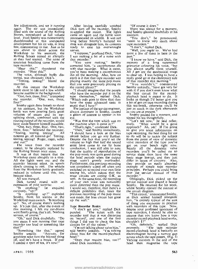
few adjustments, and set it running again. The air was immediately filled with the sound of the Rolling Stones, reproduced at full volume level. Even Smithy was momentarily dumbfounded at this unexpected development but his ire was, at long last, commencing to rise. Just as he was about to shout across the Workshop to his assistant, the Rolling Stones ceased as abruptly as they had started. The noise of sonorous breathing came from the tape recorder.
"Hear this!" thundered the recorder. "Hear this!"
The voice, although badly dis- torted, was obviously Dick's.
"Testing, testing!" blared the recorder.
At this instant the Workshop kettle came to life and a low whistle became audible in the background.
"One, two, three, four," trumpeted the recorder. "One, two, three, four!"
Smithy again drew breath to shout at his assistant, but the Workshop kettle was now pouring forth great volumes of steam and its ear- splitting shriek, combined with the roaring output of the recorder, would have made Stentor himself inaudible.
"One, two, three, four. One, two, three, four," bellowed the recorder. "Testing, testing, testing! All systems go, all systems go! Testing, testing, testing! Roger, roger, wilco and out!"
The voice from the recorder ceased, to be abruptly replaced by the Rolling Stones once more.
It was at that instant that the Workshop came abruptly to a stop. All the lights went out and the recorder became silent, its spools slowly coming to rest. The whistle from the Workshop kettle gradually reduced in volume until this, too, became silent.
All was tranquil. Dick turned round with an
expression of mild surprise. "Is anything," he enquired
curiously, "up ?" "Is anything up ?" exploded
Smithy, from his station at the Workshop main switch. "Is anything up? No, of course there's nothing up. It's just that, after the events of this morning, I felt my ear -drums were finally going, that's all. Nothing serious, of course."
"Oh," said Dick doubtfully. "Do you mean I was running that tape recorder too loud or something like that ?"
"Something like that," agreed Smithy wearily. "Anyway, for goodness sake turn the blamed thing off, and let's have a break. If ever I needed a spot of tea, it's now!"
After having carefully watched Dick turn off the recorder, Smithy re- applied the mains. The lights came on again and the kettle soon recommenced its whistle. It was not long before Smithy's battered tin mug was alongside him, its contents ready to ease his overwrought nerves.
"I suppose," proffered Dick, "that I was making a bit of a noise with that recorder."
"You were making," Smithy corrected him, "a cacophonous din with that recorder. What is more, you've been making a cacophonous din all the morning. Also, how on earth is it that that tape recorder was playing exactly the same pop music that you were previously playing on the record player ?"
"I should imagine that the people who have the recorder put it on the tape themselves," replied Dick. "Which only goes to show that they have the same advanced taste in music that I have!"
The instinct of the service engineer, always dominant in Smithy, caused a gleam of interest to appear in his eye.
"Was that the tape which was on the machine when it came in ?"
"That's right," confirmed Dick. "Then," said Smithy immediately,
"I should have a look at the bias circuit before you go any further. Despite the fact that you'd set the volume so high that half the sound must have come to me by bone conduction, I was still able to note that the quality of reproduction of the pop music was quite good during the brief periods when the output stage wasn't grossly overloaded. Furthermore, this previous recording was completely wiped off when you switched on to record your own little testing bit, which means that the erase circuits are coping O.K. as well. At the same time, the recording of your own voice was noticeably more distorted than the pop music. I would say, therefore, that there's a definite possibility that, since the previous recording of the pop music was made, the bias circuit has gone up the wall."
Tape Recorder Basics "I don't get you," replied Dick
puzzled. "The ticket with the recorder said that it was distorting on `record', and one of the first things I did was to check the bias circuits for all the valves."
"I'm not talking about valve bias," said Smithy irritably. "I'm talking about bias for the record -playback head."
"Does that require bias, too ?" asked Dick innocently.
"Of course it does." There was silence for a moment,
and Smithy glanced doubtfully at his assistant.
"You don't," he pronounced, "seem to know very much about tape recorders."
"I don't," replied Dick. "Well, you ought to. We've had
quite a few of them in here in the past."
"I know we have," said Dick, the memory of a long suppressed grievance colouring his voice, "but you always snaffle them yourself. All I get are the mechanical snags to clear up. I was hoping to have a really good go at the electronics side of that recorder this morning."
"You wouldn't," commented Smithy unkindly, "have got very far with it if you don't even know what the bias circuit for the record - playback head is meant to do. It looks as though I'd better give you a bit of gen on tape recording during this tea -break, otherwise you'll be just as much in the dark afterwards as you are at present."
Smithy paused for a moment, and sipped his tea thoughtfully.
"Let's see now," he said reflec- tively. "What would be a good approach? Ah, yes! If I'm going to give you some information on tape recording, the best thing for me to do will be to tackle the subject from the point of view of domestic valve recorders of the type you've got on your bench right now. Nearly all the domestic valve recorders you'll be called on to service these days have the same basic stage line -up, and they just differ in terms of circuitry. Also, they provide an easily absorbed example of simple tape recorder principles. Perhaps you could bring over the service manual of that recorder."
Obligingly, Dick picked up the service manual and placed it beside Smithy. He returned for his stool, whilst Smithy opened the manual at the circuit diagram.
"This circuit," commented Smithy, as Dick settled himself alongside him, "is entirely typical of the sort of thing you encounter in practice with recorders of this type. Now, despite your professed ignorance of tape recorders, I should be able to assume that you know how a tape recorder record -playback head works, shouldn't I ?"
"Oh, definitely," replied Dick promptly. "The tape recorder record -playback head is basically an electromagnet having a narrow gap across which the tape passes. (Fig. 1) Varying currents in the coil of the head then magnetise the tape
APRIL 1966 563
www.americanradiohistory.com
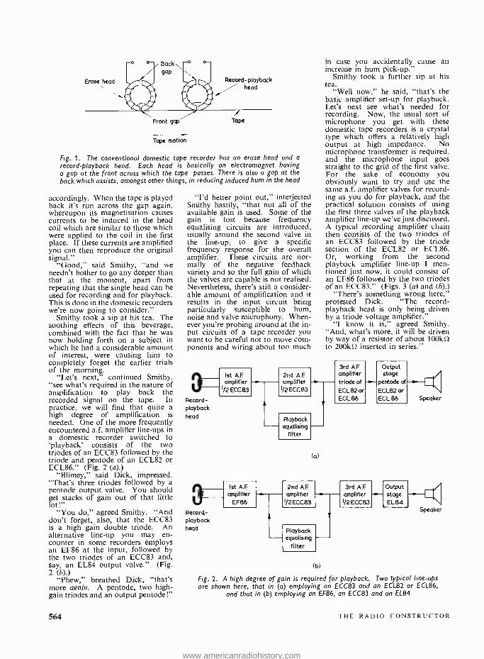
Erase head
Back
gap
Front gap
Tape motion
Record -playback head
i Tape
Fig. 1. The conventional domestic tape recorder has an erase head and a
record -playback head. Each head is basically an electromagnet having a gap at the front across which the tape passes. There is also a gap at the back which assists, amongst other things, in reducing induced hum in the head
accordingly. When the tape is played back it's run across the gap again, whereupon its magnetisation causes currents to be induced in the head coil which are similar to those which were applied to the coil in the first place. If these currents are amplified you can then reproduce the original signal."
"Good," said Smithy, "and we needn't bother to go any deeper than that at the moment, apart from repeating that the single head can be used for recording and for playback. This is done in the domestic recorders we're now going to consider."
Smithy took a sip at his tea. The soothing effects of this beverage, combined with the fact that he was now holding forth on a subject in which he had a considerable amount of interest, were causing him to completely forget the earlier trials of the morning.
"Let's next," continued Smithy, "see what's required in the nature of amplification to play back the recorded signal on the tape. In practice, we will find that quite a high degree of amplification is needed. One of the more frequently encountered a.f. amplifier line -ups in a domestic recorder switched to `playback' consists of the two triodes of an ECC83 followed by the triode and pentode of an ECL82 or ECL86." (Fig. 2 (a).)
"Blimey," said Dick, impressed. "That's three triodes followed by a pentode output valve. You should get stacks of gain out of that little lot!"
"You do," agreed Smithy. "And don't forget, also, that the ECC83 is a high gain double triode. An alternative line -up you may en- counter in some recorders employs an EF86 at the input, followed by the two triodes of an ECC83 and, say, an EL84 output valve." (Fig. 2 (b).)
"Phew," breathed Dick, "that's more again. A pentode, two high - gain triodes and an output pentode!"
564
"I'd better point out," interjected Smithy hastily, "that not all of the available gain is used. Some of the gain is lost because frequency equalising circuits are introduced, usually around the second valve in the line -up, to give a specific frequency response for the overall amplifier. These circuits are nor- mally of the negative feedback variety and so the full gain of which the valves are capable is not realised. Nevertheless, there's still a consider- able amount of amplification and it results in the input circuit being particularly susceptible to hum, noise and valve microphony. When- ever you're probing around at the in- put circuits of a tape recorder you want to be careful not to move com- ponents and wiring about too much
Record - playback head
Ist A.F amplifier
1/2 ECC83
Record-. playback head
Ist A.F amplifier
EF86
2nd A.F amplifier
1/2 ECC83
in case you accidentally cause an increase in hum pick -up."
Smithy took a further sip at his tea.
"Well now," he said, "that's the basic amplifier set -up for playback. Let's next see what's needed for recording. Now, the usual sort of microphone you get with these domestic tape recorders is a crystal type which offers a relatively high output at high impedance. No microphone transformer is required, and the microphone input goes straight to the grid of the first valve. For the sake of economy you obviously want to try and use the same a.f. amplifier valves for record- ing as you do for playback, and the practical solution consists of using the first three valves of the playback amplifier line -up we've just discussed. A typical recording amplifier chain then consists of the two triodes of an ECC83 followed by the triode section of the ECL82 or ECL86. Or, working from the second playback amplifier line -up I men- tioned just now, it could consist of an EF86 followed by the two triodes of an ECC83." (Figs. 3 (a) and (b).)
"There's something wrong here," protested Dick. "The record - playback head is only being driven by a triode voltage amplifier."
"I know it is," agreed Smithy. "And, what's more, it will be driven by way of a resistor of about 100kS2 to 200k L2 inserted in series."
Playback equalising
filter
(a)
2nd AF amplifier
1/2 ECC83
3rd AF Output amplifier stage triode of -e-- pentode of
ECLB2 or ECL82 or ECL 86 ECL 86
Playback equalising
filter
(b)
3rd A.F amplifier -0-- 1/2 ECC83
Output stage EL84
Speaker
Fig. 2. A high degree of gain is required for playback. Two typical line -ups are shown here, that in (a) employing an ECC83 and an ECL82 or ECL86,
and that in (b) employing an EF86, an ECC83 and an EL84
THE RADIO CONSTRUCTOR
www.americanradiohistory.com
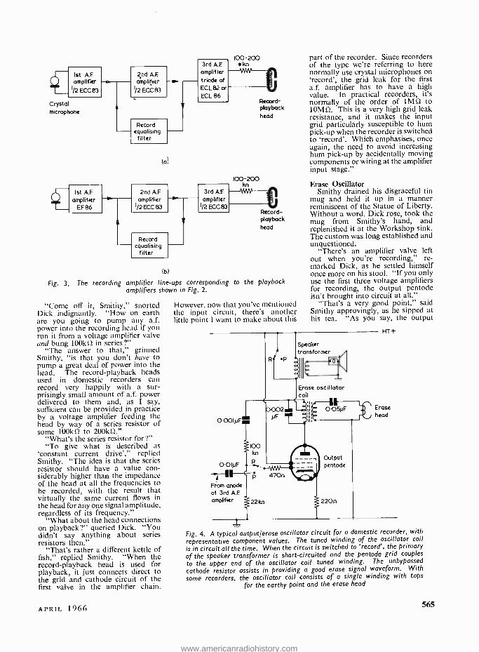
1st A.F amplifier -c
1/2 ECC 83
Crystal
microphone
Ist A.F
amplifier EF 86
2nd A.F amplitier
1/2 ECC B3
Record equalising filter
(a)
2nd A.F
amplifier 1/2 ECC 83
3rd A.F.
amplifier triode of ECL 82 or -- ECL 86
100-200 kn
Record equalising
filter
3rd AF amplifier
1/2 ECC 83
Record - playback head
part of the recorder. Since recorders of the type we're referring to here normally use crystal microphones on 'record', the grid leak for the first a.f. amplifier has to have a high value. In practical recorders, it's normally of the order of 1M û to 10Mû. This is a very high grid leak resistance, and it makes the input grid particularly susceptible to hum pick -up when the recorder is switched to 'record'. Which emphasises, once again, the need to avoid increasing hum pick -up by accidentally moving components or wiring at the amplifier input stage."
100-200 t _ Erase Oscillator
Smithy drained his disgraceful tin mug and held it up in a manner reminiscent of the Statue of Liberty. Without a word, Dick rose, took the mug from Smithy's hand, and replenished it at the Workshop sink. The custom was long established and unquestioned.
"There's an amplifier valve left out when you're recording," re- marked Dick, as he settled himself once more on his stool. "If you only
to the playback use the first three voltage amplifiers for recording, the output pentode isn't brought into circuit at all."
"That's a very good point," said Smithy approvingly, as he sipped at his tea. "As you say, the output
(b)
Fig. 3. The recording amplifier line -ups corresponding amplifiers shown in Fig. 2.
"Come off it, Smithy," snorted Dick indignantly. "How on earth are you going to pump any a.f. power into the recording head if you run it from a voltage amplifier valve and bung 100kû in series ?"
"The answer to that," grinned Smithy, "is that you don't have to pump a great deal of power into the head. The record- playback heads used in domestic recorders can record very happily with a sur- prisingly small amount of a.f. power delivered to them and, as I say, sufficient can be provided in practice by a voltage amplifier feeding the head by way of a series resistor of some 100kû to 200kû."
"What's the series resistor for ?" "To give what is described as
'constant current drive'," replied Smithy. "The idea is that the series resistor should have a value con- siderably higher than the impedance of the head at all the frequencies to be recorded, with the result that virtually the same current flows in the head for any one signal amplitude, regardless of its frequency."
"What about the head connections on playback ?" queried Dick. "You didn't say anything about series resistors then."
"That's rather a different kettle of fish," replied Smithy. "When the record- playback head is used for playback, it just connects direct to the grid and cathode circuit of the first valve in the amplifier chain.
Record - playback head
However, now that you've mentioned the input circuit, there's another little point I want to make about this
Speaker transformer
Erase oscillator coil a - 0'05pF
OoOIpF111111
0.0IpF
From anode of 3rd A.F amplifier
Output pentode
470n
22kn
HT+
Erase head
Fig. 4. A typical output /erase oscillator circuit for a domestic recorder, with representative component values. The tuned winding of the oscillator coil
is in circuit all the time. When the circuit is switched to 'record', the primary of the speaker transformer is short -circuited and the pentode grid couples
to the upper end of the oscillator coil tuned winding. The unbypassed
cathode resistor assists in providing a good erase signal waveform. With some recorders, the oscillator coil consists of a single winding with taps
for the earthy point and the erase head
APRIL 1966 565
www.americanradiohistory.com
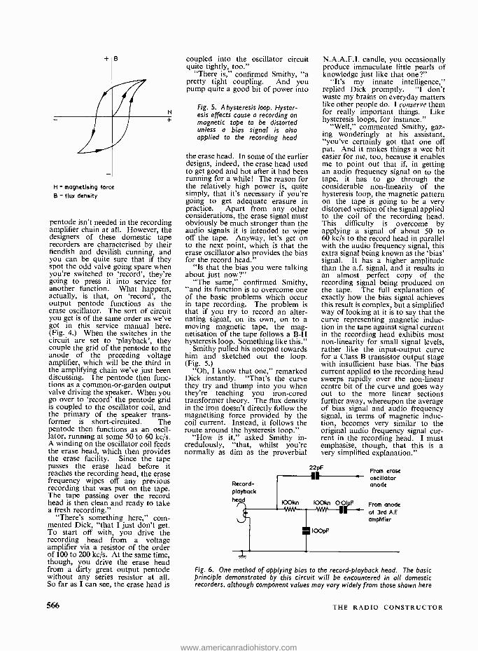
+,B
H - magnetising force
B - flux density
H
pentode isn't needed in the recording amplifier chain at all. However, the designers of these domestic tape recorders are characterised by their fiendish and devilish cunning, and you can be quite sure that if they spot the odd valve going spare when you're switched to 'record', they're going to press it into service for another function. What happens, actually, is that, on `record', the output pentode functions as the erase oscillator. The sort of circuit you get is of the same order as we've got in this service manual here. (Fig. 4.) When the switches in the circuit are set to `playback', they couple the grid of the pentode to the anode of the preceding voltage amplifier, which will be the third in the amplifying chain we've just been discussing. The pentode then func- tions as a common -or- garden output valve driving the speaker. When you go over to `record' the pentode grid is coupled to the oscillator coil, and the primary of the speaker trans- former is short -circuited. The pentode then functions as an oscil- lator, running at some 50 to 60 kc /s. A winding on the oscillator coil feeds the erase head, which then provides the erase facility. Since the tape passes the erase head before it reaches the recording head, the erase frequency wipes off any previous recording that was put on the tape. The tape passing over the record head is then clean and ready to take a fresh recording."
"There's something here," com- mented Dick, "that I just don't get. To start off with, you drive the recording head from a voltage amplifier via a resistor of the order of 100 to 200 kc /s. At the same time, though, you drive the erase head from a dirty great output pentode without any series resistor at all. So far as I can see, the erase head is
566
coupled into the oscillator circuit quite tightly, too."
"There is," confirmed Smithy, "a pretty tight coupling. And you pump quite a good bit of power into
Fig. 5. A hysteresis loop. Hyster- esis effects cause a recording on magnetic tape to be distorted unless a bias signal is also applied to the recording head
the erase head. In some of the earlier designs, indeed, the erase head used to get good and hot after it had been running for a while! The reason for the relatively high power is, quite simply, that it's necessary if you're going to get adequate erasure in practice. Apart from any other considerations, the erase signal must obviously be much stronger than the audio signals it is intended to wipe off the tape. Anyway, let's get on to the next point, which is that the erase oscillator also provides the bias for the record head."
"Is that the bias you were talking about just now ?"
"The same," confirmed Smithy, "and its function is to overcome one of the basic problems which occur in tape recording. The problem is that if you try to record an alter- nating signal, on its own, on to a moving magnetic tape, the mag- netisation of the tape follows a B -H hysteresis loop. Something like this."
Smithy pulled his notepad towards him and sketched out the loop. (Fig. 5.)
"Oh, I know that one," remarked Dick instantly. "That's the curve they try and thump into you when they're teaching you iron -cored transformer theory. The flux density in the iron doesn't directly follow the magnetising force provided by the coil current. Instead, it follows the route around the hysteresis loop."
"How is it," asked Smithy in- credulously, "that, whilst you're normally as dim as the proverbial
Record- playback he d
N.A.A.F.I. candle, you occasionally produce immaculate little pearls of knowledge just like that one ?"
"It's my innate intelligence," replied Dick promptly. "1 don't waste my brains on everyday matters like other people do. I conserve them for really important things. Like hysteresis loops, for instance."
"Well," commented Smithy, gaz- ing wonderingly at his assistant, "you've certainly got that one off pat. And it makes things a wee bit easier for me, too, because it enables me to point out that if, in getting an audio frequency signal on to the tape, it has to go through the considerable non -linearity of the hysteresis loop, the magnetic pattern on the tape is going to be a very distorted version of the signal applied to the coil of the recording head. This difficulty is overcome by applying a signal of about 50 to 60 kc /s to the record head in parallel with the audio frequency signal, this extra signal being known as the `bias' signal. It has a higher amplitude than the a.f. signal, and it results in an almost perfect copy of the recording signal being produced on the tape. The full explanation of exactly how the bias signal achieves this result is complex, but a simplified way of looking at it is to say that the curve representing magnetic induc- tion in the tape against signal current in the recording head exhibits most non -linearity for small signal levels, rather like the input- output curve for a Class B transistor output stage with insufficient base bias. The bias current applied to the recording head sweeps rapidly over the non -linear centre bit of the curve and goes way out to the more linear sections further away, whereupon the average of bias signal and audio frequency signal, in terms of magnetic induc- tion, becomes very similar to the original audio frequency signal cur- rent in the recording head. I must emphasise, though, that this is a very simplified explanation."
22pF From erase oscillator anode
IOOkn 00.1W From anode ` of 3rd A.F amplifier
Fig. 6. One method of applying bias to the record -playback head. The basic principle demonstrated by this circuit will be encountered in all domestic recorders, although component values may vary widely from those shown here
THE RADIO CONSTRUCTOR
www.americanradiohistory.com
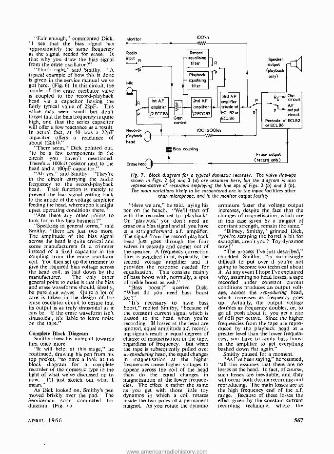
"Fair enough," commented Dick. "I see that the bias signal has approximately the same frequency as the signal needed for erase. Is that why you draw the bias signal from the erase oscillator ?"
"That's right," said Smithy. "A typical example of how this is done is given in the service manual we've got here. (Fig. 6) In this circuit, the anode of the erase oscillator valve is coupled to the record -playback head via a capacitor having the fairly typical value of 22pF. This value may seem small but don't forget that the bias frequency is quite high, and that the series capacitor will offer a low reactance as a result. In actual fact, at 50 kc /s a 22pF capacitor offers a reactance of about 1201a2."
"There seem," Dick pointed out, "to be a few components in the circuit you haven't mentioned. There's a 100kí2 resistor next to the head and a 100pF capacitor."
"Ah yes," said Smithy. "They're in the circuit carrying the audio frequency to the record- playback head. Their function is merely to prevent the bias signal getting back to the anode of the voltage amplifier feeding the head, whereupon it might upset operating conditions there."
"Are there any other points to look for in this bias business ?"
"Speaking in general terms," said Smithy, "there are just two more. The amplitude of the bias signal across the head is quite critical and some manufacturers fit a trimmer instead of a fixed capacitor in the coupling from the erase oscillator coil. You then set up the trimmer to give the required bias voltage across the head coil, as laid down by the manufacturer. The only other general point to make is that the bias and erase waveforms should, ideally, be pure sine waves. Quite a lot of care is taken in the design of the erase oscillator circuit to ensure that its output is as truly sinusoidal as it can be. If the erase waveform isn't sinusoidal, it's liable to leave noise on the tape."
Complete Block Diagram Smithy drew his notepad towards
him once more. "It will help, at this stage," he
continued, drawing his pen from his top pocket, "to have a look at the block diagram for a complete recorder of the domestic type in the light of what we've discussed up to now. I'll just sketch out what I mean."
As Dick looked on, Smithy's pen moved briskly over the pad. The Serviceman soon completed his diagram. (Fig. 7.)
Monitor o
Radio input
Mic
.- amplifier
IF; 1 /2ECC83
Ist A.F
Record - playback
head
Erase head)
Fig. 7. Block diagram for a typical domestic recorder. The valve line -ups shown in Figs. 2 (a) and 3 (a) are assumed here, but the diagram is also representative of recorders employing the line ups of Figs. 2 (b) and 3 (b). The main variations likely to be encountered are in the input facilities other
than microphone, and in the monitor output facility
IDO kn AAA 'r'rrv
gRecord equalising filter
Playback equalising
filter
Gain control
2nd A.F
amplifier.
1/2 ECC 83
Speaker output
(playback only) h
3rd A.F
amplifier triode of ..--- ECL82 or R
ECLB6
100 -200kn
TBias coupling
R Osc circuit AF
P output circuit
Pentode of ECL82 or ECL86
Erase output (record only)
"Here we are," he said, laying his pen on the bench. "We'll start off with the recorder set to `playback'. On `playback' you don't need an erase or a bias signal and all you have is a straightforward a.f. amplifier. The signal from the record- playback head just goes through the four valves in cascade and comes out of the speaker. A frequency correction filter is switched in at, typically, the second voltage amplifier and it provides the response needed for equalisation. This consists mainly of bass boost with, normally, a spot of treble boost as well."
"Bass boost ?" queried Dick. "What do you need bass boost for
"It's necessary to have bass boost," replied Smithy, "because of the constant current signal which is passed to the head when you're recording. If losses at the head are ignored, equal amplitude a.f. record- ing signals result in equal degrees of change of magnetisation in the tape, regardless of frequency. But when the tape is subsequently pulled over a reproducing head, the equal changes in magnetisation at the higher frequencies cause higher voltages to appear across the coil of the head than do the equal changes in magnetisation at the lower frequen- cies. The effect is rather the same as you get with those little toy dynamos in which a coil rotates inside the two poles of a permanent magnet. As you rotate the dynamo
armature faster the voltage output increases, despite the fact that the changes of magnetisation, which are in this case given by a magnet of constant strength, remain the same."
"Blimey, Smithy," grinned Dick, "you're scraping the barrel a bit for examples, aren't you ? Toy dynamos now!"
"The process I've just described," chuckled Smithy, "is surprisingly difficult to put over if you're not going to become too technical about it. At any event I hope I've explained why, assuming no head losses, a tape recorded under constant current conditions produces an output volt- age, across the reproducing head, which increases as frequency goes up. Actually, the output voltage doubles as frequency doubles, or, to go all posh about it, you get a rise of 6dB per octave. Since the higher frequencies from the tape are repro- duced by the playback head at a greater level than the lower frequen- cies, you have to apply bass boost in the amplifier to get everything bashed down flat again."
Smithy paused for a moment. "As I've been saying," he resumed,
"all this assumes that there are no losses at the head. In fact, of course, such losses are inevitable, and they will occur both during recording and reproducing. The main losses are at the high frequency end of the a.f. range. Because of these losses the effect given by the constant current recording technique, where the
APRIL 1966 567
www.americanradiohistory.com
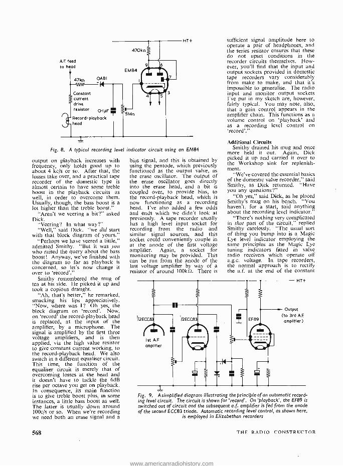
A.F feed to head
Fig. 8. A typical recording level indicator circuit using an EM84
output on playback increases with frequency, only holds good up to about 4 kc /s or so. After that, the losses take over, and a practical tape recorder of the domestic type is almost certain to have some treble boost in the playback circuits as well, in order to overcome them. Usually, though, the bass boost is a lot higher than the treble boost."
"Aren't we veering a bit ?" asked Dick.
"Veering? In what way ?" "Well," said Dick. "we did start
with that block diagram of yours." "Perhaps we have veered a little,"
admitted Smithy. "But it was you who raised the query about the bass boost! Anyway, we've finished with the diagram so far as playback is concerned, so let's now change it over to 'record'."
Smithy remembered the mug of tea at his side. He picked it up and took a copious draught.
"Ah, that's better," he remarked, smacking his lips appreciatively. "Now, where was I? Oh yes, the block diagram on 'record'. Now, on 'record' the record- playback head is replaced, at the input of the amplifier, by a microphone. The signal is amplified by the first three voltage amplifiers, and is then applied, via the high value resistor to give constant current working, to the record- playback head. We also switch in a different equaliser circuit. This time, the function of the equaliser circuit is merely that of overcoming losses at the head and it doesn't have to tackle the 6dB rise per octave you get on playback. In consequence, its main function is to give treble boost plus, in some instances, a little bass boost as well. The latter is usually down around 100c /s or so. When we're recording we need both an erase signal and a
568
bias signal, and this is obtained by using the pentode, which previously functioned as the output valve, as the erase oscillator. The output of the erase oscillator goes directly into the erase head, and a bit is coupled over, to provide bias, to the record- playback head, which is now functioning as a recording head. I've also added a few odds and ends which we didn't look at previously. A tape recorder usually has a high level input socket for recording from the radio and similar signal sources, and this socket could conveniently couple in at the anode of the first voltage amplifier. Again, a socket for monitoring may be provided. This can be run from the anode of the last voltage amplifier by way of a resistor of around 100kí2. There is
sufficient signal amplitude here to operate a pair of headphones, and the series resistor ensures that these do not upset conditions in the recorder circuits themselves. How- ever, you'll find that the input and output sockets provided in domestic tape recorders vary considerably from make to make, and that it's impossible to generalise. The radio input and monitor output sockets I've put in my sketch are, however, fairly typical. You may note, also, that a gain control appears in the amplifier chain. This functions as a volume control on 'playback' and as a recording level control on 'record'."
Additional Circuits Smithy drained his mug and once
more held it out. Again, Dick picked it up and carried it over to the Workshop sink for replenish- ment.
"We've covered the essential basics of the domestic valve recorder," said Smithy, as Dick returned. "Have you any questions ?"
"Oh yes," said Dick, as he placed Smithy's mug on his bench. "You haven't, for a start, said anything about the recording level indicator."
"There's nothing very complicated in that part of the circuit," replied Smithy carelessly. "The usual sort of thing you bump into is a Magic Eye level indicator employing the same principles as the Magic Eye tuning indicators fitted in valve radio receivers which operate off a.g.c. voltage. In tape recorders, the normal approach is to rectify the a.f. at the end of the constant
Ist A.E
amplifier
HT+
Output (to 3rd A.F amplifier)
Fig. 9. A simp died diagram i lustrating the principle of an automatic record- ing level circuit. The circuit is shown for 'record'. On 'playback', the EF89 is
switched out of circuit and the subsequent a.f. amplifier is fed from the anode of the second ECC83 triode. Automatic recording level control, as shown here,
is employed in Elizabethan recorders
THE RADIO CONSTRUCTOR
www.americanradiohistory.com
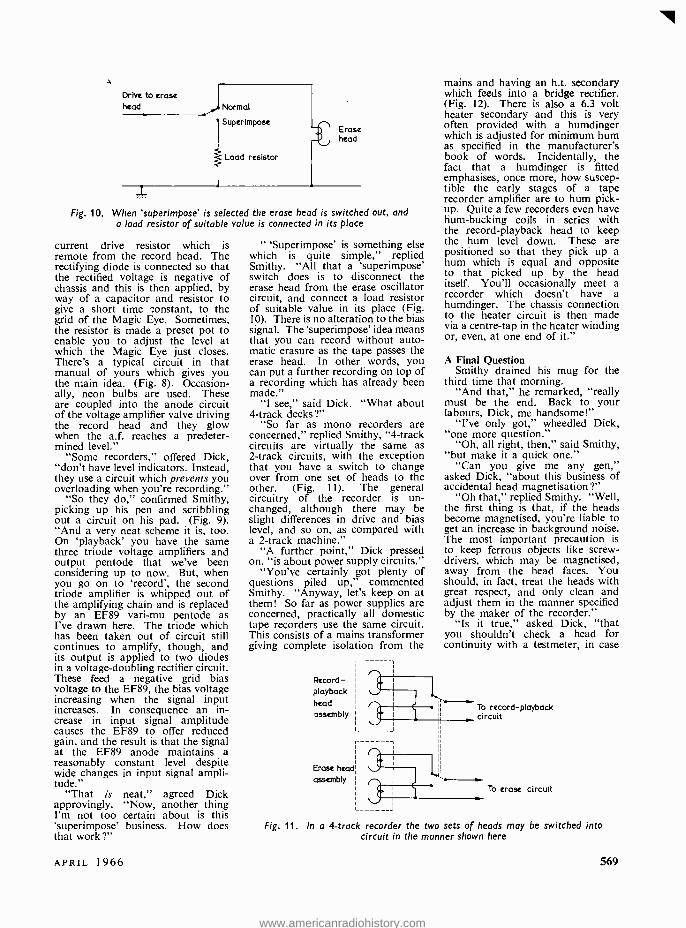
Drive to erase head Normal
Superimpose
Load resistor
Erase head
Fig. 10. When 'superimpose' is selected the erase head is switched out, and a load resistor of suitable value is connected in its place
current drive resistor which is remote from the record head. The rectifying diode is connected so that the rectified voltage is negative of chassis and this is then applied, by way of a capacitor and resistor to give a short time constant, to the grid of the Magic Eye. Sometimes, the resistor is made a preset pot to enable you to adjust the level at which the Magic Eye just closes. There's a typical circuit in that manual of yours which gives you the main idea. (Fig. 8). Occasion- ally, neon bulbs are used. These are coupled into the anode circuit of the voltage amplifier valve driving the record head and they glow when the a.f. reaches a predeter- mined level."
"Some recorders," offered Dick, "don't have level indicators. Instead, they use a circuit which prevents you overloading when you're recording."
"So they do," confirmed Smithy, picking up his pen and scribbling out a circuit on his pad. (Fig. 9). "And a very neat scheme it is, too. On 'playback' you have the same three triode voltage amplifiers and output pentode that we've been considering up to now. But, when you go on to 'record', the second triode amplifier is whipped out of the amplifying chain and is replaced by an EF89 vari -mu pentode as I've drawn here. The triode which has been taken out of circuit still continues to amplify, though, and its output is applied to two diodes in a voltage -doubling rectifier circuit. These feed a negative grid bias voltage to the EF89, the bias voltage increasing when the signal input increases. In consequence an in- crease in input signal amplitude causes the EF89 to offer reduced gain, and the result is that the signal at the EF89 anode maintains a reasonably constant level despite wide changes in input signal ampli- tude."
"That is neat," agreed Dick approvingly. "Now, another thing I'm not too certain about is this 'superimpose' business. How does that work ?"
" 'Superimpose' is something else which is quite simple," replied Smithy. "All that a 'superimpose' switch does is to disconnect the erase head from the erase oscillator circuit, and connect a load resistor of suitable value in its place (Fig. 10). There is no alteration to the bias signal. The 'superimpose' idea means that you can record without auto- matic erasure as the tape passes the erase head. In other words, you can put a further recording on top of a recording which has already been made."
"I see," said Dick. "What about 4 -track decks ?"
"So far as mono recorders are concerned," replied Smithy, "4 -track circuits are virtually the same as 2 -track circuits, with the exception that you have a switch to change over from one set of heads to the other. (Fig. I1). The general circuitry of the recorder is un- changed, although there may be slight differences in drive and bias level, and so on, as compared with a 2 -track machine."
"A further point," Dick pressed on, "is about power supply circuits."
"You've certainly got plenty of questions piled up," commented Smithy. "Anyway, let's keep on at them! So far as power supplies are concerned, practically all domestic tape recorders use the same circuit. This consists of a mains transformer giving complete isolation from the
Record - playback head
assembly
Erase head
assembly
mains and having an h.t. secondary which feeds into a bridge rectifier. (Fig. 12). There is also a 6.3 volt heater secondary and this is very often provided with a humdinger which is adjusted for minimum hum as specified in the manufacturer's book of words. Incidentally, the fact that a humdinger is fitted emphasises, once more, how suscep- tible the early stages of a tape recorder amplifier are to hum pick- up. Quite a few recorders even have hum -bucking coils in series with the record -playback head to keep the hum level down. These are positioned so that they pick up a hum which is equal and opposite to that picked up by the head itself. You'll occasionally meet a recorder which doesn't have a humdinger. The chassis connection to the heater circuit is then made via a centre -tap in the heater winding or, even, at one end of it."
A Final Question Smithy drained his mug for the
third time that morning. "And that," he remarked, "really
must be the end. Back to your labours, Dick, me handsome!"
"I've only got," wheedled Dick, "one more question."
"Oh, all right, then," said Smithy, "but make it a quick one."
"Can you give me any gen," asked Dick, "about this business of accidental head magnetisation ?"
"Oh that," replied Smithy. "Well, the first thing is that, if the heads become magnetised, you're liable to get an increase in background noise. The most important precaution is to keep ferrous objects like screw- drivers, which may be magnetised, away from the head faces. You should, in fact, treat the heads with great respect, and only clean and adjust them in the manner specified by the maker of the recorder."
"Is it true," asked Dick, "that you shouldn't check a head for continuity with a testmeter, in case
To record - playback circuit
To erase circuit
Fig. 11. In a 4 -track recorder the two sets of heads may be switched into circuit in the manner shown here
APRIL 1966 569
www.americanradiohistory.com
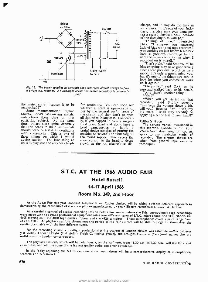
Bridge rectifier
On -Off
yl.
Mains supply to deck
o AC.
mains
1
Fig. 12. The power supplies in domestic tape recorders almost always employ a bridge h.t. rectifier. A humdinger across the heater secondary is commonly
used
the meter current causes it to be magnetised ?"
"Some manufacturers," replied Smithy, "don't pass on any specific instructions these days on that particular subject. At the same time, others state quite definitely that the heads in their instruments should never be tested for continuity with a testmeter. This is one of those things on which I would advise caution. The best thing to do is to play safe and not check heads
for continuity. You can soon tell whether a head is open -circuit or not by the general performance of the circuit, and they don't go open all that often in any case. Incidental- ly, if you happen to have a magne- tised erase head and don't have a head demagnetiser to hand, a useful dodge consists of putting the machine to 'record' and switching off the mains supply. This causes the erase current in the head to decay slowly as the h.t. electrolytics dis-
charge, and it may do the trick in some cases. If it's one of your lucky days, this idea may even demagne- tise a record- playback head, because of the decaying bias voltage,"
"Talking of bias," interjected Dick, "I suppose you suggested lack of bias with that tape recorder I was working on just before tea -break because previous recordings hadn't had the same distortion as when I recorded on it myself."
"That's right," said Smithy. "The bias coupling may have gone wrong since those previous recordings were made. It's only a guess, mind you, but it's one of the things you should look for when you commence work on it again."
"Okeydoke," said Dick, as he rose and walked back to his bench.
"And there's another thing." "Yes v "When you get started on that
recorder," said. Smithy sweetly, "just keep the volume down a bit, will you? Because if you don't, my old mate, I shall very speedily be applying a bit of bias to your head!"
Editor's Note The 'service manual' mentioned in
this month's episode of "In Your Workshop" does not, of course, apply to any particular model of recorder. The circuits shown are taken from general tape recorder techniques.
S.T.C. AT THE 1966 AUDIO FAIR Hotel Russell
14-17 April 1966
Room No. 249, 2nd Floor
At the Audio Fair this year Standard Telephones and Cables Limited will be taking a rather different approach in demonstrating the capabilities of the microphones manufactured by their Electro- Mechanical Division at Harlow. At a carefully controlled studio recording session held a few weeks before the Fair, stereophonic tape recordings were made with top -grade professional equipment using four different types of S.T.C. microphone: the 4113 ribbon, the
4105 moving coil, the 4038 high quality ribbon, and the 4126 capacitor. These microphones cover a price range from f12 to £100. At playback sessions throughout the period of the Fair visitors will be able to judge for themselves the results obtainable with the four different types.
For the recording session a top -flight professional string quartet of London players was assembled -Max Salpeter (1st violin), Leonard Dight (2nd violin), Keith Cummings (Viola), and Douglas Cameron (Cello) -all names that are well -known to London concert -goers.
The playback sessions, which will be held hourly, on the half -hour, from 11.30 a.m. to 7.30 p.m., will last for about 25 minutes, and will use some of the highest quality audio equipment available.
In the lobby adjoining the S.T.C. demonstration room there will be a comprehensive display of microphones, headsets and accessories.
570 THE RADIO CONSTRUCTOR
www.americanradiohistory.com
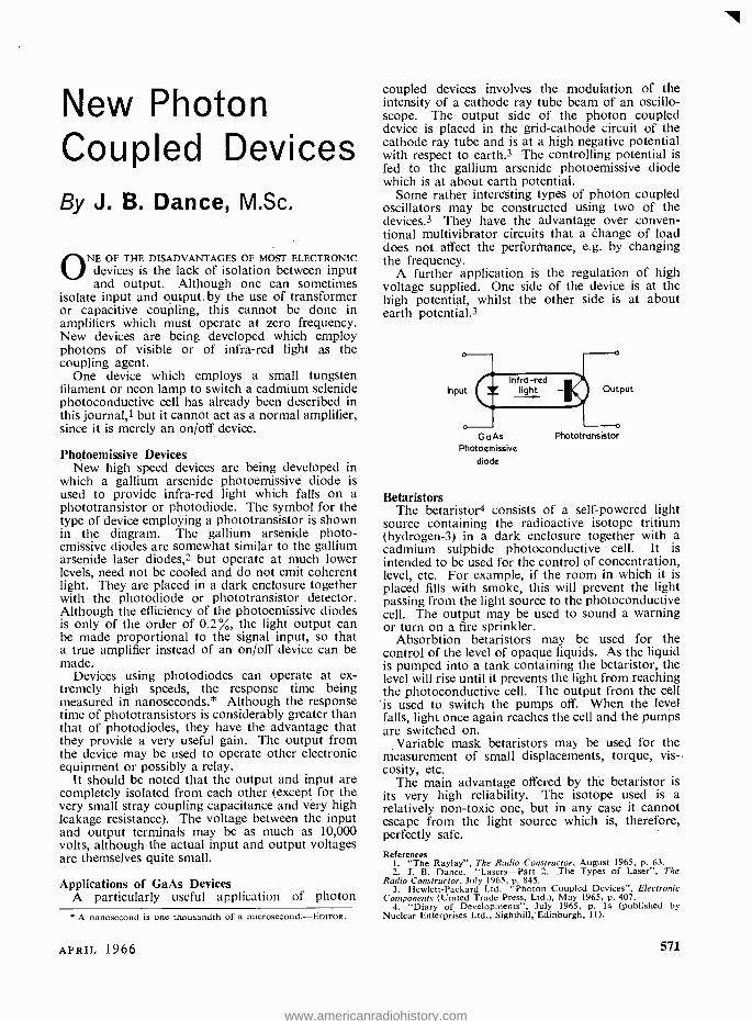
New Photon Coupled Devices By J. B. Dance, M.Sc,
ONE OF THE DISADVANTAGES OF MOST ELECTRONIC devices is the lack of isolation between input and output. Although one can sometimes
isolate input and output, by the use of transformer or capacitive coupling, this cannot be done in amplifiers which must operate at zero frequency. New devices are being developed which employ photons of visible or of infra -red light as the coupling agent.
One device which employs a small tungsten filament or neon lamp to switch a cadmium selenide photoconductive cell has already been described in this journal,I but it cannot act as a normal amplifier, since it is merely an on /off device.
Photoemissive Devices New high speed devices are being developed in
which a gallium arsenide photoemissive diode is used to provide infra -red light which falls on a phototransistor or photodiode. The symbol for the type of device employing a phototransistor is shown in the diagram. The gallium arsenide photo - emissive diodes are somewhat similar to the gallium arsenide laser diodes,2 but operate at much lower levels, need not be cooled and do not emit coherent light. They are placed in a dark enclosure together with the photodiode or phototransistor detector. Although the efficiency of the photoemissive diodes is only of the order of 0.2%, the light output can be made proportional to the signal input, so that a true amplifier instead of an on /off device can be made.
Devices using photodiodes can operate at ex- tremely high speeds, the response time being measured in nanoseconds.* Although the response time of phototransistors is considerably greater than that of photodiodes, they have the advantage that they provide a very useful gain. The output from the device may be used to operate other electronic equipment or possibly a relay.
It should be noted that the output and input are completely isolated from each other (except for the very small stray coupling capacitance and very high leakage resistance). The voltage between the input and output terminals may be as much as 10,000 volts, although the actual input and output voltages are themselves quite small.
Applications of GaAs Devices A particularly useful application of photon
A nanosecond is one thousandth of a microsecond. -EDITOR.
coupled devices involves the modulation of the intensity of a cathode ray tube beam of an oscillo- scope. The output side of the photon coupled device is placed in the grid- cathode circuit of the cathode ray tube and is at a high negative potential with respect to earth.3 The controlling potential is fed to the gallium arsenide photoemissive diode which is at about earth potential.
Some rather interesting types of photon coupled oscillators may be constructed using two of the devices.3 They have the advantage over conven- tional multivibrator circuits that a change of load does not affect the performhance, e.g. by changing the frequency.
A further application is the regulation of high voltage supplied. One side of the device is at the high potential, whilst the other side is at about earth potential.3
Ga As Photoemissive
diode
Phototransistor
Betaristors The betaristor4 consists of a self -powered light
source containing the radioactive isotope tritium (hydrogen -3) in a dark enclosure together with a cadmium sulphide photoconductive cell. It is intended to be used for the control of concentration, level, etc. For example, if the room in which it is placed fills with smoke, this will prevent the light passing from the light source to the photoconductive cell. The output may be used to sound a warning or turn on a fire sprinkler.
Absorbtion betaristors may be used for the control of the level of opaque liquids. As the liquid is pumped into a tank containing the betaristor, the level will rise until it prevents the light from reaching the photoconductive cell. The output from the cell is used to switch the pumps off. When the level falls, light once again reaches the cell and the pumps are switched on.
Variable mask betaristors may be used for the measurement of small displacements, torque, vis- cosity, etc.
The main advantage offered by the betaristor is its very high reliability. The isotope used is a relatively non -toxic one, but in any case it cannot escape from the light source which is, therefore, perfectly safe.
References 1. "The Raylay ", The Radio Constructor, August 1965, p. 63. 2. J. B. Dance. "Lasers -Part 2. The Types of Laser ", The
Radio Constructor, July 1965, p. 845. 3. Hewlett- Packard Ltd. "Photon Coupled Devices ", Electronic
Components (United Trade Press, Ltd.), May 1965, p. 407. 4. "Diary of Developments ", July 1965, p. 14 (published by
Nuclear Enterprises Ltd., Sighthill, Edinburgh, II).
APRIL 1966 571
www.americanradiohistory.com
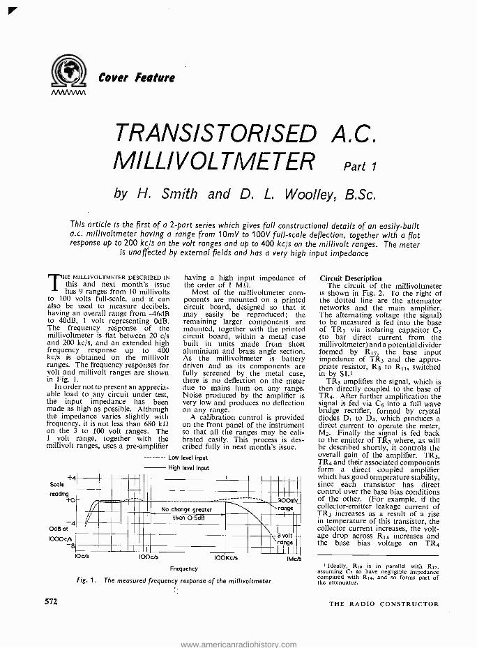
I
Cover Feature
TRANSISTORISED A.C. MI LLI V OL TMETER Part
by H. Smith and D. L. Woolley, B.Sc.
This article is the first of a 2 -part series which gives full constructional details of an easily -built a.c. millivoltmeter having a range from 10mV to 100V full -scale deflection, together with a flat response up to 200 kc/s on the volt ranges and up to 400 kc /s on the millivolt ranges. The meter
is unaffected by external fields and has a very high input impedance
THE MILLIVOLTMETER DESCRIBED IN this and next month's issue has 9 ranges from 10 millivolts
to 100 volts full -scale, and it can also be used to measure decibels, having an overall range from -46dB to 40dB, 1 volt representing OdB. The frequency response of the millivoltmeter is flat between 20 c/s and 200 kc /s, and an extended high frequency response up to 400 kc /s is obtained on the millivolt ranges. The frequency responses for volt and millivolt ranges are shown in Fig. 1.
In order not to present an apprecia- able load to any circuit under test, the input impedance has been made as high as possible. Although the impedance varies slightly with frequency, it is not less than 680 k12 on the 3 to 100 volt ranges. The 1 volt range, together with the millivolt ranges, uses a pre -amplifier
+ Scale
reading +0
OdB at
1000 c/s -8
572
having a high input impedance of the order of 1 M12.
Most of the millivoltmeter com- ponents are mounted on a printed circuit board, designed so that it may easily be reproduced; the remaining larger components are mounted, together with the printed circuit board, within a metal case built in units made from sheet aluminium and brass angle section. As the millivoltmeter is battery driven and as its components are fully screened by the metal case, there is no deflection on the meter due to mains hum on any range. Noise produced by the amplifier is very low and produces no deflection on any range.
A calibration control is provided on the front panel of the instrument so that all the ranges may be cali- brated easily. This process is des- cribed fully in next month's issue.
- Low level input
High level input
11111 --En --
11111 II 1II 300mV - - _1 ,11tII Na change greater `.I ̀ range I
,, 11111 than O.SdB \\ 11111 111111 E 3 volt I
v ,'II . range I ME C C/s IOOKc/s
Frequency
Fig. 1. The measured frequency response of the millivoltmeter
IMcFs
Circuit Description The circuit of the millivoltmeter
is shown in Fig. 2. To the right of the dotted line are the attenuator networks and the main amplifier. The alternating voltage (the signal) to be measured is fed into the base of TR3 via isolating capacitor C2 (to bar direct current from the millivoltmeter) and a potential divider formed by R17, the base input impedance of TR3 and the appro- priate resistor, R8 to R11, switched in by Si.'
TR3 amplifies the signal, which is then directly coupled to the base of TR4. After further amplification the signal is fed via C6 into a full wave bridge rectifier, formed by crystal diodes DI to D4, which produces a direct current to operate the meter, M2. Finally the signal is fed back to the emitter of TR3 where, as will be described shortly, it controls the overall gain of the amplifier. TR3, TR4 and their associated components form a direct coupled amplifier which has good temperature stability, since each transistor has direct control over the base bias conditions of the other. (For example, if the collector- emitter leakage current of TR3 increases as a result of a rise in temperature of this transistor, the collector current increases, the volt- age drop across R18 increases and the base bias voltage on TR4
I Ideally, R19 is in parallel with R17, assuming C7 to have negligible impedance compared with R19, and so forms part of the attenuator.
THE RADIO CONSTRUCTOR
www.americanradiohistory.com
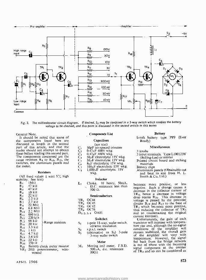
High range input
Pre- amplifier w Amplifier
52 "..."
-9V
Low range input
o
Comron
Fig. 2. The millivoltmeter circuit diagram. If desired, S2 may be combined in a 3 -way switch which enables the battery voltage to be checked, and this point Is discussed in the second article in this series
General Note. It should be noted that some of
the components listed here are discussed at length in the second part of this article, and that the reader should not attempt to obtain them before reading this second part. The components concerned are the range resistors R8 to R16, R21, the switches, the aluminium panels and the meter.
Resistors (All fixed values watt 5% high
stability. See text) R1 1MÛ R2 47 k0 R3 47 kû R4 lO kS2 R5 22 kû R6 2.2 kit R7 2.7 kit R8 22 Mil R9 6.8 Mû Rio 2.2 Mû R11 680 kû R12 220 kS1 R13 68 kit R14 20 kû R15 3.3 kit R16 1 kit R17 4.7 kit R18 5.6 kit R19 22 kû R20 150 11
R21 Battery check meter resistor VR5 5012 potentiometer, wire -
wound
Range resistors
Components List
Capacitors (see text)
C1 50pF air -spaced trimmer C2 0.47µF 400V wkg. C3 0.47µF 400V wkg. C4 50µF electrolytic I5V wkg. C5 501/F electrolytic 15V wkg. C6 811F electrolytic 15V wkg. C7 1001.LF electrolytic 15V wkg. C8 1,000µF electrolytic 15V
wkg.
Inductor L1 Choke. 10 henry, 50mA.
D.C. resistance less than 500 Q.
Semiconductors TR' 0C44 TR2 0C45 TR3 0C42 TR4 0076 D1,2, 3,4 0A81
Switches Si 1 -pole 11 -way, wafer switch,
ceramic insulation S2 s.p.s.t. switch S3 (alternative to S2) 3 -pole
3 -way wafer switch
Meter M5 Moving coil meter. F.S.D.
500µA, d.c. resistance 10012
Battery 5 ..volt battery type PP9 (Ever
Ready)
Miscellaneous 3 knobs 3 input terminals. Type L1001/1W
(Belling -Lee) or similar Printed circuit board and etching
materials Battery clips Aluminium panels (Obtainable cut
and bent to size from H. L. Smith & Co. Ltd.)
becomes more positive, or less negative. Such a change causes a decrease in the collector current of TR4, hence a decrease in voltage drop across R20. This decrease in voltage is passed by the potential divider R19 and R17 to the base of TR3 which becomes more positive, thus reducing the collector of TR3 and so counteracting the original current increase).
Unfortunately, the gain of each transistor will increase with tempera- ture rise and, although the no- signal conditions of the amplifier will remain stabilised, the overall gain of the amplifier will vary with temperature. However, the signal fed back from the bridge network is out of phase with the incoming signal component at the emitter of TR3 and so can be considered as
APRIL 1966 573
www.americanradiohistory.com
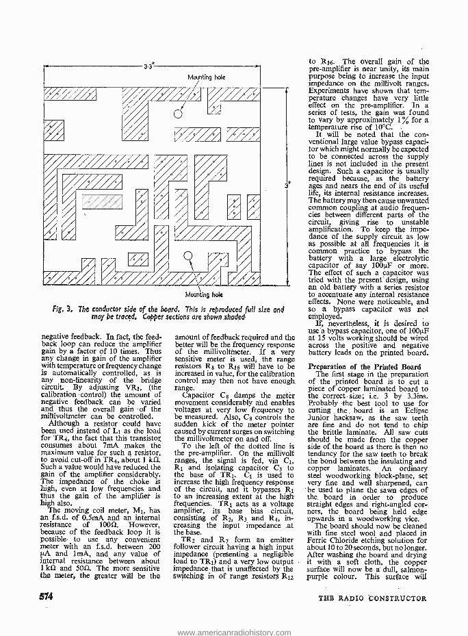
3.3*
Mounting bole
X///// ////,
// Weer AP' Ad A
/
Mounting hole
Fig. 3. The conductor side of the board. This is reproduced full size and may be traced, Copper sections are shown shaded
3
negative feedback. In fact, the feed- back loop can reduce the amplifier gain by a factor of 10 times. Thus any change in gain of the amplifier with temperature or frequency change is automatically controlled, as is any non -linearity of the bridge circuit. By adjusting VRI, (the calibration 'control) the amount of negative feedback can be varied and thus the overall gain of the millivoltmeter can be controlled.
Although a resistor could have been used instead of Li as the load for TR4, the fact that this transistor consumes about 7mA makes the maximum value for such a resistor, to avoid cut -off in TR4, about 1 kn. Such a value would have reduced the gain of the amplifier considerably. The impedance of the choke is high, even at low frequencies and thus the gain of the amplifier is high also.
The moving coil meter, M1, has an f.s.d. of 0.5mA and an internal resistance of 1001 However, because of the feedback loop it is possible to use any convenient meter with an f.s.d. between 200 ILA and lmA, and any value of internal resistance between about 1 kû and 5012, The more sensitive the meter, the greater will be the
574
amount of feedback required and the better will be the frequency response of the millivoltmeter. If a very sensitive meter is used, the range resistors Rs to R16 will have to be increased in value, for the calibration control may then not have enough, range.
Capacitor Cs damps the meter movement considerably and enables voltages at very low frequency to be measured. Also, C$ controls the sudden kick of the meter pointer caused by current surges on switching the millivoltmeter on and off.
To the left of the dotted line is the pre -amplifier. On the millivolt ranges, the signal is fed, via Ci, Rt and isolating capacitor C3 to the base of TR1 C1 is used to increase the high frequency response of the circuit, and it bypasses . R1 to an increasing extent at the high frequencies. TRl acts as a voltage amplifier, its base bias circuit, consisting of R2, R3 and 114, in- creasing the input impedance at the base.
TR2 and R7 form an emitter follower circuit having a high input impedance (presenting a negligible load to TR1) and a very low output impedance that is unaffected by the switching in of range resistors R12
to R16. The overall gain of the pre -amplifier is near unity, its main purpose being to increase the input impedance on the millivolt ranges. Experiments have shown that tem- perature changes have very little effect on the pre -amplifier. In a series of tests, the gain was found to vary by approximately 1% for a temperature rise of 10 °C.
It will be noted that the con - ventional large value bypass capaci- tor which might normally be expected to be connected across the supply lines is not included in the present design. Such a capacitor is usually required because, as the battery ages and nears the end of its useful life, its internal resistance increases. The battery may then cause unwanted common coupling at audio frequen- cies between different parts of the circuit, giving rise to unstable amplification. To keep the impe- dance of the supply circuit as low as possible at all frequencies it is common practice to bypass the battery with a large electrolytic capacitor of say 100µF or more. The effect of such a capacitor was tried with the present design, using an old battery with a series resistor to accentuate any internal resistance effects. None were noticeable, and so a bypass capacitor was not employed.
It, nevertheless, it is desired to use'a bypass capacitor, one of 100µF at 15 volts working should be wired across the positive and negative battery leads on the printed board.
Preparation of the Printed Board The first stage in the preparation
of the printed board is to cut a piece of copper laminated board to the correct size; i.e. 3 by 3.3ins. Probably the best tool to use for cutting
. the . board is an Eclipse
Junior hacksaw, as the saw teeth are fine and do not tend to chip the brittle laminate. All saw cuts should be made from the copper side of the board as there is then no tendancy for the saw teeth to break the bond between the insulating and copper laminates. An ordinary steel woodworking block- plane, set very fine and well sharpened, can be used to plane the sawn edges of the. board in order to produce straight edges and right -angled cor- ners, the board being held edge upwards in a woodworking vice.
The board should now be cleaned with fine steel wool and placed in Ferric Chloride etching solution for about 10 to 20 seconds, but no longer. After washing the board and drying it with a soft cloth, the copper surface will now be a dull, salmon - purple colour. This surface will
THE RADIO 'CONSTRUCTOR
www.americanradiohistory.com

take pencil marks easily, whereas the original shiny surface is very difficult to mark. With the aid of a sharp HB pencil and a small ruler marked in tenths of an inch, the printed circuit design may now be copied from Fig. 3 (which is reproduced to scale) directly on to the board. Only the outlines of the copper strips to be left unetched need be drawn.
A resist has now to be applied to the copper surface in order to protect the actual circuit from the etching solution. Any oil -based or cellulose -based paint will act as a resist but Brushing Belco is recom- mended as it dries fairly rapidly and has been used by the authors very successfully on many occasions. The paint, in any chosen colour, should now be painted over all the copper areas that are to remain unetched, using a No. 2 or similar fine water colour brush. Care must be taken to apply a fairly thick, hole -free layer, avoiding the areas of copper to be etched.
If painting has been concluded satisfactorily it is possible to etch the board almost immediately, as the paint recommended need not dry fully before it resists the action of the etching solution. However, for those who find if difficult to paint a good straight edge, the best policy is to leave the paint to dry hard overnight and touch -up the design with a sharp pen -knife and ruler. The uneven edges and rounded corners may be cut straight and the surplus paint easily removed.
The etching solution has already been mentioned. It is prepared by dissolving Ferric Chloride crystals in water, a suitable ratio being: -
250gm. of Ferric Chloride to 500cc. of water; i.e. about 8oz. of Ferric Chloride to 1 pint of water.
This ratio produces a strong solution which dissolves copper rapidly. Weaker solutions do the job equally well, but take a longer time. At normal room temperature the strong solution will take only 10 to 15 minutes to etch through the copper normally used on lamin- ated boards. - The solution may be used over and over again, but it takes a longer time to etch through the copper as it becomes more exhausted. If the board is actually floated on the surface of the Ferric Chloride solution, copper side down- wards, the etching process is com- pleted speedily. Care must be taken to avoid air bubbles, which adhere to the surface and prevent etching.
When all the unprotected copper has been dissolved, the board should be removed from the etching solu-
The copper side of the printed circuit board after etching
tion, washed in tap water and dried. Although the paint could now be removed, it is better to leave it in situ as a protection for the copper whilst the holes are drilled in the board. A No. 55 twist -drill or one of similar size is used to drill all but the mounting holes, drilling being carried out with a hand drill or mounted power drill. A piece of wood should be used to back -up the laminate to prevent chipping as the drill breaks through the board. All drilling should start from the copper side of the board. The two mounting holes in the board should
be drilled with a No. 30 or }in drill. The paint should now be removed
with acetone or cellulose thinners and the board cleaned carefully with fine steel wool.
Mounting Components on the Printed Board
As the millivoltmeter is a piece of test equipment, it is desirable that its components have good stability so that the overall char- acteristics of the instrument vary as little as possible with time. There- fore, every component used in the prototype instrument was bought
The components rroJnted in pcsition on the boord
APRIL 1966 575
www.americanradiohistory.com
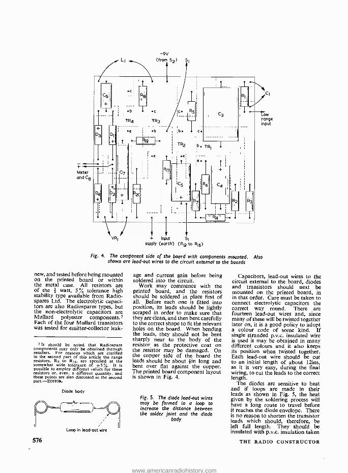
Meter and Ce
-9V (from S2)
6
i + D3 Di,
C7
174
+
2 ' I l
/ VRI
.b .c',
TR4
b
Po I-
c R5
b. i
TR2
el
11
C5
+ Input supply (earth)
C3
C.
'b. TRI i
e. l
R6
SI
(RI2 to R16)
Fig. 4. The component side of the board with components mounted. shown are lead -out wires to the circuit external to the boards
new, and tested before being mounted on the printed board or within the metal case. All resistors are of the f watt, 5 % tolerance high stability type available from Radio - spares Ltd. The electrolytic capaci- tors are also Radiospares types, but the non -electrolytic capacitors are Mullard polyester components.? Each of the four Mullard transistors was tested for emitter -collector leak-
2 It should be noted that Radiospare components may only be obtained through retailers. For reasons which are clarified in the second part of this article the range resistors, R8 to R16, are specified at the somewhat wide tolerance of ±5 ° %,. It is possible to employ different values for these resistors or, even, a different quantity, and these points are also discussed in the second part.- EDrroR.
Diode body
Loop in lead -out wire
576
age and current gain before being soldered into the circuit.
Work may commence with the printed board, and the resistors should be soldered in place first of all. Before each one is fitted into position, its leads should be lightly scraped in order to make sure that they are clean, and then bent carefully to the correct shape to fit the relevant holes on the board. When bending the leads, they should not be bent sharply near to the body of the resistor as the protective coat on the resistor may be damaged. On the copper side of the board the leads should be about fin long and bent over flat against the copper. The printed board component layout is shown in Fig. 4.
Fig. 5. The diode lead -out wires may be formed in a loop to increase the distance between the solder joint and the diode
body
ow range input
Also
Capacitors, lead -out wires to the circuit external to the board, diodes and transistors should next be mounted on the printed board, in in that order. Care must be taken to connect electrolytic capacitors the correct way round. There are fourteen lead -out wires and, since many of these will be twisted together later on, it is a good policy to adopt a colour code of some kind. If single stranded p.v.c. insulated wire is used it may be obtained in many different colours and it also keeps its position when twisted together. Each lead -out wire should be cut to an initial length of about 12ins, as it is very easy, during the final wiring, to cut the leads to the correct length.
The diodes are sensitive to heat and if loops are made in their leads as shown in Fig. 5, the heat given by the soldering process will have a long route to travel before it reaches the diode envelope. There is no reason to shorten the transistor leads which should, therefore, be left full length. They should be insulated with p.v.c. insulation taken
THE RADIO CONSTRUCTOR
www.americanradiohistory.com
from the lead -out wires. Provided that an excessively long time is not taken to solder each transistor
lead, there should be no need to use a heat -shunt. If the soldering iron is at the correct temperature
and cored solder is employed, it should be possible to make a really sound joint in less than five seconds.
(To be concluded)
IN THE LAST ARTICLE IN THIS SERIES WE CONCLUDED our discussion on the triode as voltage amplifier and examined some practical triodes, as are
encountered in commercially manufactured radio and audio amplifying equipment.
We now turn our attention to a further factor which has to be considered in relation to the triode, this being Miller Effect, after which we shall introduce the subject of the triode as oscillator.
cathode). More complicated expressions for inter - electrode capacitances may also be encountered, two typical examples being Cg_h+k and cg_atl. The first of these expressions refers to the capacitance given with the grid as one "plate" of the effective capacitor, and the heater and cathode joined together as the other. The second (which is usually applied to valves having more complicated electrode structures than the triode) refers to the capacitance
understanding Miller Effect, and the
Triode Oscillator
By W. G. Morley
Inter- Electrode Capacitance Since the electrodes of a triode valve are in fairly
close proximity to each other, it follows that a capacitance exists between them. Capacitances also exist between the leads and pins connecting to the electrodes, these capacitances being in parallel with the capacitances existing between the associated electrodes themselves.
In conventional voltage amplifier triodes the inter -electrode capacitances are quite small and are normally less than some 2.5 pF. These small capacitances have negligible effect on circuit opera- tion in some applications, but in others they are of importance and have to be taken into account. Inter -electrode capacitances are identified by the small letter "c" followed by suffix letters designating the electrodes concerned.' Thus, the expression ca_g represents the capacitance between anode and grid, cg_k the capacitance between grid and cathode and ca_k the capacitance between anode and cathode. Also of importance is ck_h, which represents the capacitance between cathode and heater. With directly heated triodes, inter -electrode capacitances to the filament are referred to as cg_f and ca_f, the letter "f" (for filament) replacing the letter "k" (for
t The small "c ", instead of a capital letter, is used because the capacitance is inside the valve. See the footnote on page 325 of the December 1965 issue.
APRIL 1966
radio between the grid as one "plate" and all the remaining electrodes joined together as the other. Modern practice has introduced two further expressions, these being cin and cout. The expression cmu stands for the capacitance between the input electrode (the grid) and all other electrodes except the output electrode (the anode) joined together. The expression cout refers to the capacitance between the output electrode (the anode) and all other electrodes except the input electrode (the grid) joined together.
The expressions for inter -electrode capacitance just given will be found in the specifications for their products which are issued by the valve manufac- turers. It may be noted, in passing, that the capacitance figures quoted by manufacturers nor- mally apply, unless otherwise stated, to the valve when it is cold (i.e. no heater or filament supply applied).
577
www.americanradiohistory.com
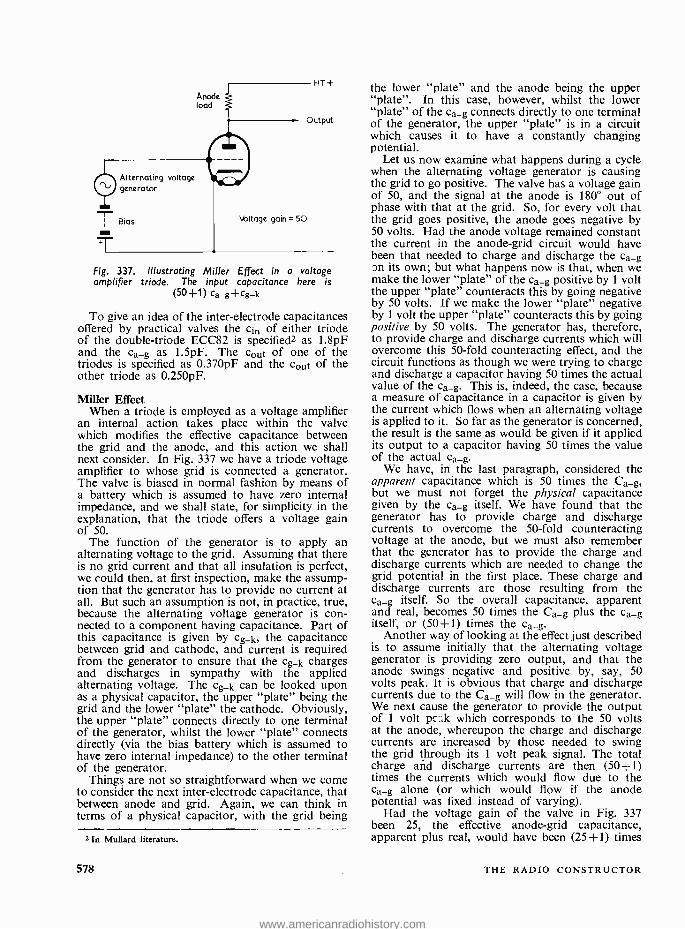
Anode load
Alternating voltage generator
T Bias
T'
HT+
Output
Voltage gain= 50
Fig. 337. Illustrating Miller Effect in a voltage amplifier triode. The input capacitance here is
(50 +1) Ca-
g +cg -k
To give an idea of the inter -electrode capacitances offered by practical valves the cin of either triode of the double- triode ECC82 is specified2 as 1.8pF and the Ca_g as 1.5pF. The Gout of one of the triodes is specified as 0.370pF and the tout of the other triode as 0.250pF.
Miller Effect When a triode is employed as a voltage amplifier
an internal action takes place within the valve which modifies the effective capacitance between the grid and the anode, and this action we shall next consider. In Fig. 337 we have a triode voltage amplifier to whose grid is connected a generator. The valve is biased in normal fashion by means of a battery which is assumed to have zero internal impedance, and we shall state, for simplicity in the explanation, that the triode offers a voltage gain of 50.
The function of the generator is to apply an alternating voltage to the grid. Assuming that there is no grid current and that all insulation is perfect, we could then, at first inspection, make the assump- tion that the generator has to provide no current at all. But such an assumption is not, in practice, true, because the alternating voltage generator is can - nected to a component having capacitance. Part of this capacitance is given by cg_k, the capacitance between grid and cathode, and current is required from the generator to ensure that the cg_k charges and discharges in sympathy with the applied alternating voltage. The cg_k can be looked upon as a physical capacitor, the upper "plate" being the grid and the lower "plate" the cathode. Obviously, the upper "plate" connects directly to one terminal of the generator, whilst the lower "plate" connects directly (via the bias battery which is assumed to have zero internal impedance) to the other terminal of the generator.
Thing are not so straightforward when we come to consider the next inter -electrode capacitance, that between anode and grid. Again, we can think in terms of a physical capacitor, with the grid being
2 In Mullard literature.
578
the lower "plate" and the anode being the upper "plate ". In this case, however, whilst the lower "plate" of the ca_g connects directly to one terminal of the generator, the upper "plate" is in a circuit which causes it to have a constantly changing potential.
Let us now examine what happens during a cycle when the alternating voltage generator is causing the grid to go positive. The valve has a voltage gain of 50, and the signal at the anode is 1 80° out of phase with that at the grid. So, for every volt that the grid goes positive, the anode goes negative by 50 volts. Had the anode voltage remained constant the current in the anode -grid circuit would have been that needed to charge and discharge the ca_g on its own; but what happens now is that, when we make the lower "plate" of the ca_g positive by 1 volt the upper "plate" counteracts this by going negative by 50 volts. If we make the lower "plate" negative by 1 volt the upper "plate" counteracts this by going positive by 50 volts. The generator has, therefore, to provide charge and discharge currents which will overcome this 50 -fold counteracting effect, and the circuit functions as though we were trying to charge and discharge a capacitor having 50 times the actual value of the ca_g. This is, indeed, the case, because a measure of capacitance in a capacitor is given by the current which flows when an alternating voltage is applied to it. So far as the generator is concerned, the result is the same as would be given if it applied its output to a capacitor having 50 times the value of the actual ca_g.
We have, in the last paragraph, considered the apparent capacitance which is 50 times the Ca_g, but we must not forget the physical capacitance given by the ca_g itself. We have found that the generator has to provide charge and discharge currents to overcome the 50 -fold counteracting voltage at the anode, but we must also remember that the generator has to provide the charge and discharge currents which are needed to change the grid potential in the first place. These charge and discharge currents are those resulting from the ca_g itself. So the overall capacitance, apparent and real, becomes 50 times the Ca_g plus the ca_g itself, or (50+1) times the ca_g.
Another way of looking at the effect just described is to assume initially that the alternating voltage generator is providing zero output, and that the anode swings negative and positive by, say, 50 volts peak. It is obvious that charge and discharge currents due to the Ca_g will flow in the generator. We next cause the generator to provide the output of 1 volt pc k which corresponds to the 50 volts at the anode, whereupon the charge and discharge currents are increased by those needed to swing the grid through its 1 volt peak signal. The total charge and discharge currents are then (50 +1) times the currents which would flow due to the ca_g alone (or which would flow if the anode potential was fixed instead of varying).
Had the voltage gain of the valve in Fig. 337 been 25, the effective anode -grid capacitance, apparent plus real, would have been (25 +1) times
THE RADIO CONSTRUCTOR
www.americanradiohistory.com
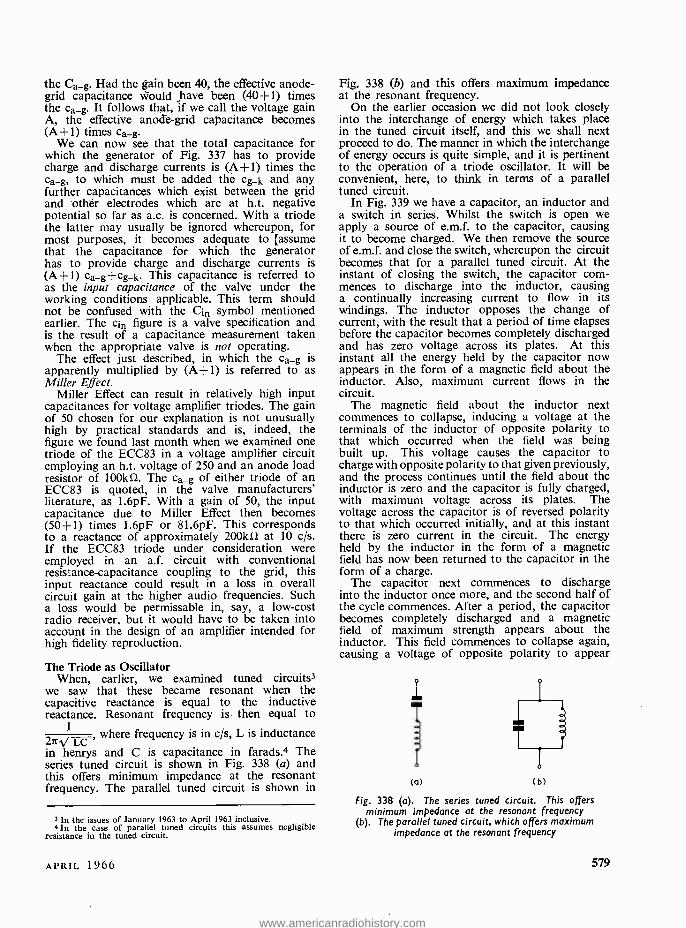
the Ca_g. Had the Lain been 40, the effective anode - grid capacitance would have been (40+1) times the ca_g. It follows that, if we call the voltage gain A, the effective anode -grid capacitance becomes (A +1) times ca_g.
We can now see that the total capacitance for which the generator of Fig. 337 has to provide charge and discharge currents is (A +1) times the ca_g, to which must be added the cg_k and any further capacitances which exist between the grid and other electrodes which are at h.t. negative potential so far as a.c. is concerned. With a triode the latter may usually be ignored whereupon, for most purposes, it becomes adequate to [assume that the capacitance for which the generator has to provide charge and discharge currents is (A+1) ca_g +cg_k. This capacitance is referred to as the input capacitance of the valve under the working conditions applicable. This term should not be confused with the Cin symbol mentioned earlier. The cin figure is a valve specification and is the result of a capacitance measurement taken when the appropriate valve is not operating.
The effect just described, in which the Ca_g is apparently multiplied by (A +1) is referred to as Miller Effect.
Miller Effect can result in relatively high input capacitances for voltage amplifier triodes. The gain of 50 chosen for our explanation is not unusually high by practical standards and is, indeed, the figure we found last month when we examined one triode of the ECC83 in a voltage amplifier circuit employing an h.t. voltage of 250 and an anode load resistor of 100kû. The ca_g of either triode of an ECC83 is quoted, in the valve manufacturers' literature, as 1.6pF. With a gain of 50, the input capacitance due to Miller Effect then becomes (50 +1) times 1.6pF or 81.6pF. This corresponds to a reactance of approximately 200kû at 10 c /s. If the ECC83 triode under consideration were employed in an a.f. circuit with conventional resistance -capacitance coupling to the grid, this input reactance could result in a loss in overall circuit gain at the higher audio frequencies. Such a loss would be permissable in, say, a low -cost radio receiver, but it would have to be taken into account in the design of an amplifier intended for high fidelity reproduction.
The Triode as Oscillator When, earlier, we examined tuned circuits3
we saw that these became resonant when the capacitive reactance is equal to the inductive reactance. Resonant frequency is then equal to
1 where frequency is in c /s, L is inductance 21tÁ/ LC ' in henrys and C is capacitance in farads.4 The series tuned circuit is shown in Fig. 338 (a) and this offers minimum impedance at the resonant frequency. The parallel tuned circuit is shown in
3 In the issues of January 1963 to April 1963 inclusive. 4 In the case of parallel tuned circuits this assumes negligible
resistance in the tuned circuit.
Fig. 338 (b) and this offers maximum impedance at the resonant frequency.
On the earlier occasion we did not look closely into the interchange of energy which takes place in the tuned circuit itself, and this we shall next proceed to do. The manner in which the interchange of energy occurs is quite simple, and it is pertinent to the operation of a triode oscillator. It will be convenient, here, to think in terms of a parallel tuned circuit.
In Fig. 339 we have a capacitor, an inductor and a switch in series. Whilst the switch is open we apply a source of e.m.f. to the capacitor, causing it to become charged. We then remove the source of e.m.f. and close the switch, whereupon the circuit becomes that for a parallel tuned circuit. At the instant of closing the switch, the capacitor com- mences to discharge into the inductor, causing a continually increasing current to flow in its windings. The inductor opposes the change of current, with the result that a period of time elapses before the capacitor becomes completely discharged and has zero voltage across its plates. At this instant all the energy held by the capacitor now appears in the form of a magnetic field about the inductor. Also, maximum current flows in the circuit.
The magnetic field about the inductor next commences to collapse, inducing a voltage at the terminals of the inductor of opposite polarity to that which occurred when the field was being built up. This voltage causes the capacitor to charge with opposite polarity to that given previously, and the process continues until the field about the inductor is zero and the capacitor is fully charged, with maximum voltage across its plates. The voltage across the capacitor is of reversed polarity to that which occurred initially, and at this instant there is zero current in the circuit. The energy held by the inductor in the form of a magnetic field has now been returned to the capacitor in the form of a charge.
The capacitor next commences to discharge into the inductor once more, and the second half of the cycle commences. After a period, the capacitor becomes completely discharged and a magnetic field of maximum strength appears about the inductor. This field commences to collapse again, causing a voltage of opposite polarity to appear
Ti 1
b
(a) (b)
Fig. 338 (a). The series tuned circuit. This offers minimum impedance at the resonant frequency
(b). The parallel tuned circuit, which offers maximum impedance at the resonant frequency
APRIL 1966 579
www.americanradiohistory.com
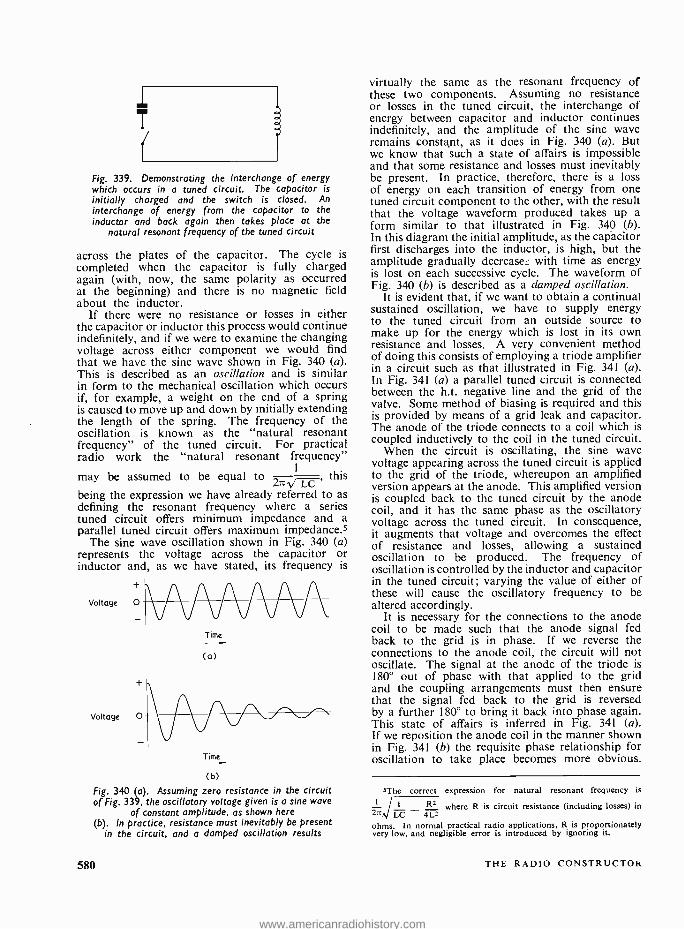
Fig. 339. Demonstrating the interchange of energy which occurs in a tuned circuit. The capacitor is initially charged and the switch is closed. An interchange of energy from the capacitor to the inductor and back again then takes place at the
natural resonant frequency of the tuned circuit
across the plates of the capacitor. The cycle is completed when the capacitor is fully charged again (with, now, the same polarity as occurred at the beginning) and there is no magnetic field about the inductor.
If there were no resistance or losses in either the capacitor or inductor this process would continue indefinitely, and if we were to examine the changing voltage across either component we would find that we have the sine wave shown in Fig. 340 (a). This is described as an oscillation and is similar in form to the mechanical oscillation which occurs if, for example, a weight on the end of a spring is caused to move up and down by initially extending the length of the spring. The frequency of the oscillation is known as the "natural resonant frequency" of the tuned circuit. For practical radio work the "natural resonant frequency"
may be assumed to be equal to 2nd LC this
being the expression we have already referred to as defining the resonant frequency where a series tuned circuit offers minimum impedance and a parallel tuned circuit offers maximum impedance.5
The sine wave oscillation shown in Fig. 340 (a) represents the voltage across the capacitor or inductor and, as we have stated, its frequency is
Voltage
Voltage
Time
(a)
Time
(b)
Fig. 340 (a). Assuming zero resistance in the circuit of Fig. 339, the oscillatory voltage given is a sine wave
of constant amplitude, as shown here (b). In practice, resistance must inevitably be present
in the circuit, and a damped oscillation results
580
virtually the same as the resonant frequency of these two components. Assuming no resistance or losses in the tuned circuit, the interchange of energy between capacitor and inductor continues indefinitely, and the amplitude of the sine wave remains constant, as it does in Fig. 340 (a). But we know that such a state of affairs is impossible and that some resistance and losses must inevitably be present. In practice, therefore, there is a loss of energy on each transition of energy from one tuned circuit component to the other, with the result that the voltage waveform produced takes up a form similar to that illustrated in Fig. 340 (b). In this diagram the initial amplitude, as the capacitor first discharges into the inductor, is high, but the amplitude gradually decreaseL with time as energy is lost on each successive cycle. The waveform of Fig. 340 (b) is described as a damped oscillation.
It is evident that, if we want to obtain a continual sustained oscillation, we have to supply energy to the tuned circuit from an outside source to make up for the energy which is lost in its own resistance and losses. A very convenient method of doing this consists of employing a triode amplifier in a circuit such as that illustrated in Fig. 341 (a). In Fig. 341 (a) a parallel tuned circuit is connected between the h.t. negative line and the grid of the valve. Some method of biasing is required and this is provided by means of a grid leak and capacitor. The anode of the triode connects to a coil which is coupled inductively to the coil in the tuned circuit.
When the circuit is oscillating, the sine wave voltage appearing across the tuned circuit is applied to the grid of the triode, whereupon an amplified version appears at the anode. This amplified version is coupled back to the tuned circuit by the anode coil, and it has the same phase as the oscillatory voltage across the tuned circuit. In consequence, it augments that voltage and overcomes the effect of resistance and losses, allowing a sustained oscillation to be produced. The frequency of oscillation is controlled by the inductor and capacitor in the tuned circuit ; varying the value of either of these will cause the oscillatory frequency to be altered accordingly.
It is necessary for the connections to the anode coil to be made such that the anode signal fed back to the grid is in phase. If we reverse the connections to the anode coil, the circuit will not oscillate. The signal at the anode of the triode is 180° out of phase with that applied to the grid and the coupling arrangements must then ensure that the signal fed back to the grid is reversed by a further 180° to bring it back into phase again. This state of affairs is inferred in Fig. 341 (a). If we reposition the anode coil in the manner shown in Fig. 341 (b) the requisite phase relationship for oscillation to take place becomes more obvious.
5The correct expression for natural resonant frequency is
l I R2
2n LC 4L2 ohms. In normal practical radio applications, R is proportionately very low, and negligible error is introduced by ignoring it.
where R is circuit resistance (including losses) in
THE RADIO CONSTRUCTOR
www.americanradiohistory.com
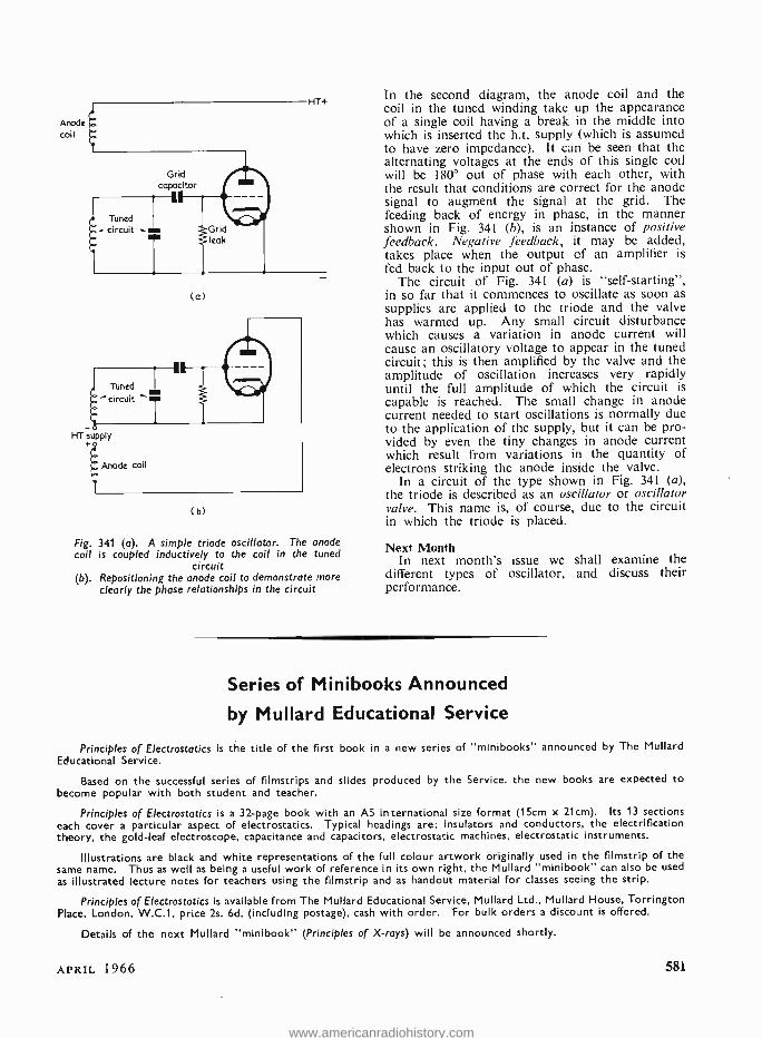
HT+
Grid capacitor
(a)
HT supply
Anode coil
(b)
Fig. 341 (a). A simple triode oscillator. The anode coil is coupled inductively to the coil in the tuned
circuit (b). Repositioning the anode coil to demonstrate more
clearly the phase relationships in the circuit
In the second diagram, the anode coil and the coil in the tuned winding take up the appearance of a single coil having a break in the middle into which is inserted the h.t. supply (which is assumed to have zero impedance). It can be seen that the alternating voltages at the ends of this single coil will be 180° out of phase with each other, with the result that conditions are correct for the anode signal to augment the signal at the grid. The feeding back of energy in phase, in the manner shown in Fig. 341 (b), is an instance of positive feedback. Negative feedback, it may be added, takes place when the output of an amplifier is fed back to the input out of phase.
The circuit of Fig. 341 (a) is "self- starting ", in so far that it commences to oscillate as soon as supplies are applied to the triode and the valve has warmed up. Any small circuit disturbance which causes a variation in anode current will cause an oscillatory voltage to appear in the tuned circuit; this is then amplified by the valve and the amplitude of oscillation increases very rapidly until the full amplitude of which the circuit is capable is reached. The small change in anode current needed to start oscillations is normally due to the application of the supply, but it can be pro- vided by even the tiny changes in anode current which result from variations in the quantity of electrons striking the anode inside the valve.
In a circuit of the type shown in Fig. 341 (a), the triode is described as an oscillator or oscillator valve. This name is, of course, due to the circuit in which the triode is placed.
Next Month In next month's issue we shall examine the
different types of oscillator, and discuss their performance.
Series of Minibooks Announced
by Mullard Educational Service
Principles of Electrostatics is the title of the first book in a new series of "minibooks" annourced by The Mullard Educational Service.
Based on the successful series of filmstrips and slides produced by the Service. the new books are expected to become popular with both student and teacher.
Principles of Electrostatics is a 32 -page book with an AS international size format (15cm x 21cm). Its 13 sections each cover a particular aspect of electrostatics. Typical headings are: insulators and conductors, the electrification theory, the gold -leaf electroscope, capacitance and capacitors, electrostatic machines, electrostatic instruments.
Illustrations are black and white representations of the full colour artwork originally used in the filmstrip of the same name. Thus as well as being a useful work of reference in its own right, the Mullard "minibook" can also be used
as illustrated lecture notes for teachers using the filmstrip and as handout material for classes seeing the strip.
Principles of Electrostatics is available from The Mullard Educational Service, Mullard Ltd., Mullard House, Torrington Place, London, W.C.1, price 2s. 6d. (including postage), cash with order. For bulk orders a discount is offered.
Details of the next Mullard "minibook" (Principles of X -rays) will be announced shortly.
APRIL 1966 581
www.americanradiohistory.com
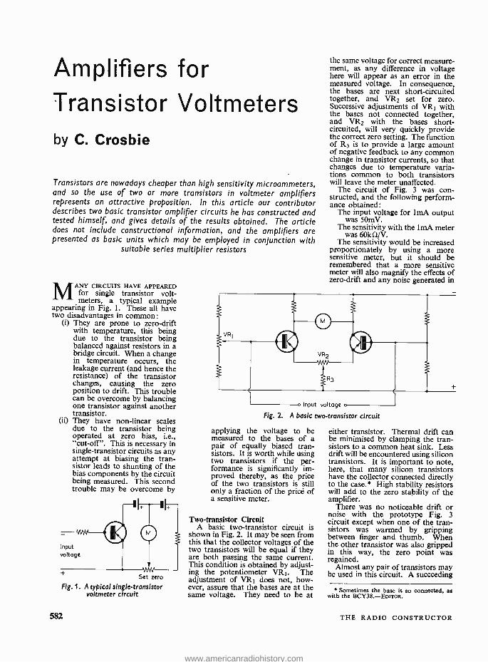
Amplifiers for Transistor Voltmeters by C. Crosbie
Transistors are nowadays cheaper than high sensitivity microammeters, and so the use of two or more transistors in voltmeter amplifiers represents an attractive proposition. In this article our contributor describes two basic transistor amplifier circuits he has constructed and tested himself, and gives details of the results obtained. The article does not include constructional information, and the amplifiers are presented as basic units which may be employed in conjunction with
suitable series multiplier resistors
MANY CIRCUITS HAVE APPEARED for single transistor volt- meters, a typical example
appearing in Fig. 1. These all have two disadvantages in common:
(i) They are prone to zero -drift with temperature, this being due to the transistor being balanced against resistors in a bridge circuit. When a change in temperature occurs, the leakage current (and hence the resistance) of the transistor changes, causing the zero position to drift. This trouble can be overcome by balancing one transistor against another transistor.
(ii) They have non -linear scales due to the transistor being operated at zero bias, i.e., "cut -off ". This is necessary in single- transistor circuits as any attempt at biasing the tran- sistor leads to shunting of the bias components by the circuit being measured. This second trouble may be overcome by
Input voltage
t Set zero
Fig. 1. A typical single- transistor voltmeter circuit
582
the same voltage for correct measure- ment, as any difference in voltage here will appear as an error in the measured voltage. In consequence, the bases are next short- circuited together, and VR2 set for zero. Successive adjustments of VRl with the bases not connected together, and VR2 with the bases short- circuited, will very quickly provide the correct zero setting. The function of R3 is to provide a large amount of negative feedback to any common change in transistor currents, so that changes due to temperature varia- tions common to both transistors will leave the meter unaffected.
The circuit of Fig. 3 was con- structed, and the following perform- ance obtained:
The input voltage for 1mA output was 50mV.
The sensitivity with the lmA meter was 60kû /V.
The sensitivity would be increased proportionately by using a more sensitive meter, but it should be remembered that a more sensitive meter will also magnify the effects of zero -drift and any noise generated in
o Input voltage o
Fig. 2. A basic two-transistor circuit
applying the voltage to be measured to the bases of a pair of equally biased tran- sistors. It is worth while using two transistors if the per- formance is significantly im- proved thereby, as the price of the two transistors is still only a fraction of the price of a sensitive meter.
Two-transistor Circuit A basic two -transistor circuit is
shown in Fig. 2. It may be seen from this that the collector voltages of the two transistors will be equal if they are both passing the same current. This condition is obtained by adjust- ing the potentiometer VR1. The adjustment of VR1 does not, how- ever, assure that the bases are at the same voltage. They need to be at
either transistor. Thermal drift can be minimised by clamping the tran- sistors to a common heat sink. Less drift will be encountered using silicon transistors. It is important to note, here, that many silicon transistors have the collector connected directly to the case.' High stability resistors will add to the zero stability of the amplifier.
There was no noticeable drift or noise with the prototype Fig. 3 circuit except when one of the tran- sistors was warmed by gripping between finger and thumb. When the other transistor was also gripped in this way, the zero point was regained.
Almost any pair of transistors may be used in this circuit. A succeeding
Sometimes the base is so connected, as with the BCY38.- Enrroa.
THE RADIO CONSTRUCTOR
www.americanradiohistory.com
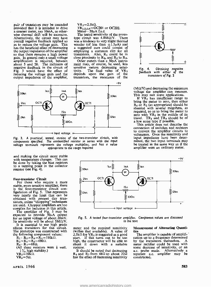
pair of transistors may be cascaded provided that it is intended to drive a coarser meter, say IOmA, as other- wise thermal drift will be excessive. Alternatively, the circuit may have overall negative feedback applied so as to reduce the voltage gain. This has the beneficial effect of decreasing the output impedance of the amplifier so that there remains a high power gain. In general only a small voltage amplification is required, between about 5 and 20. The inclusion of negative feedback in the circuit of Fig. 3 would have the effect of reducing the voltage gain and the output impedance of the amplifier,
VR3 = 2.5kí1. TR1,2,3,4 =0C201 or 0C202. Meter =50p.A f.s.d. The tested sensitivity of the proto-
type circuit was 4.8MS1 /V. There was a tendency to very slight thermal wander (of less than ± 1.5µA) and a suggested cure could consist of employing a common clip for all transistors. Also, R1 could be in close proximity to Rs, and R2 to R9.
Other meters than a 501/A instru- ment may, of course, be used, less sensitive meters decreasing sensi- tivity. The final value of VR3 depends upon the gain of the transistors, the resistance of the
o Input voltage o
Fig. 3. A practical, tested, version of the two -transistor circuit, with components specified. The unidentified resistor in series with the input voltage terminals represents the voltage multiplier, and has a value
appropriate to the range required
-9V
33kn
12kn
and making the circuit more stable with temperature changes. This can be done by taking the bias resistors to a tapping point in the collector resistor (see Fig. 4).
Four -transistor Circuit For those who require a more
stable, more sensitive amplifier, there is the four -transistor circuit con- figuration of Fig. 5. This represents very nearly the limit that can be obtained with present day tran- sistors, unless "chopping" techniques are used. Chopper amplifiers are too compex for inclusion in this article.
The amplifier of Fig. 5 may be expected to provide 501,A output for an input voltage of about 20mV. Its sensitivity will be about 5Mû /V.
It is essential to use high grade silicon transistors for this circuit. The prototype was constructed with the following component values:
R1= R2= R8= R9= 510kS1. R3= R5= R6= 68051. R4 =R7 =6851. (All these resistors were it watt.
1 %, high stability.) VR1= 10kí1. VR2 =5íl.
APRIL 1966
Fig. 4. Obtaining negative feedback with either of the
transistors of Fig. 2
(Mil /V) and decreasing the minimum voltage the amplifier can measure. This may suit some applications.
If VR1 has insufficient range to bring the meter to zero, then either R1 or R2 (as appropriate) should be shunted with several megohms, as required, so as to bring the meter to zero with VR1 in the middle of its travel. TR1 and TR4 should be of a low noise type if possible.
This article does not describe the connection of switches and resistors to convert the amplifier circuits to voltmeters. Once the sensitivity and input impedance have been deter- mined, the two input terminals may be treated in the same way as if the amplifier were an ordinary meter.
-9V
12kn
o Input voltage o
Fig. 5. A tested four- transistor amplifier. Component values are discussed in the text
meter and the required sensitivity (within that available). A value of 2.5k11 for VR3 is suggested as a good start. If this turns out to be too high, the constructor will be able to shunt it down with a suitable resistor.
It should be noted that decreasing R4 and R7 from 6851 to about 2251 has the effect of decreasing sensitivity
Measurement of Alternating Quanti- ties
The amplifier is capable of amplifi- cation up to a frequency determined by the transistors themselves. A meter rectifier could be used with some decrease of sensitivity, or an a.c. probe made. Alternatively a separate a.c. amplifier may be constructed.
583
www.americanradiohistory.com
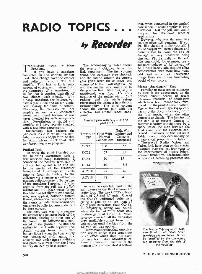
RADIO TOPICS .. o Recorder
T RANSISTORS WORK IN BOTH
directions. If you have a transistor
connected in the earthed emitter mode then change over the emitter and collector leads, it will still amplify. This fact is fairly well - known, of course, and it stems from the symmetry of a transistor, in so far that it consists basically of two diodes back -to -back. With a p.n.p. transistor, for instance, you have a p.n. diode and an n.p diode, both sharing the same n section. Obviously, the transistor will not amplify so well when connected wrong way round because it was never intended for such an applica- tion. Nevertheless, it should still amplify, as I have recently checked with a few little experiments.
Incidentally, just because the particular issue in which this con- tribution appears happens to be that for April, please don't think that any leg- pulling is in progress!
Praticai Tests To prove the point I carried out
the following experiment with a few assorted p.n.p transistors. I connected the positive terminals of a 3 volt battery and a 1.5 volt cell to the emitter of the transistor being tested. I next applied 3 volts negative from the battery to the collector via a testmeter switched to measure collector current. To the base of the transistor I applied 1.5 volts negative from the cell via a 15kí2 resistor and a 0 -100µA meter. When this base bias (of slightly less than 0.1 mA) was applied, collector current flowed, whereupon the current gain of the transistor under these conditions was given by collector current divided by base current.
The next step was to transpose the emitter and collector leads of the transistor, altering no other part of the circuit. The collector now con- nected to the positive line and the emitter to the 3 volts negative line. Again, current from the 3 volt battery flowed when the base supply was connected and, again, the effective gain under these conditions was given by current from the 3 volt battery divided by base current.
584
The accompanying Table shows the results I obtained from this little experiment. The first column shows the transistor type checked, and the second column the current gain given when the collector was connected to the 3 volt negative line and the emitter was connected to the positive line. Base bias, as just mentioned, was from 1.5 volts negative of the emitter via a 15kí2 resistor, and the whole set -up represented the ultimate in orthodox respectability. The third column shows the current gain with the collector and emitter leads trans- posed.
Current gain with Ve.e =3V and Ib 3.1mA
Transistor Type
Gain With Normal
Connections
Gain With Emitter and Collector
Transposed
0072 100 2.5
OC72 67 1.7
0C44 50 15
0C44 110 8.5
ACY18 75 3.7
ACY18 48 4
As is to be expected most of the gain figures in the third column are pretty low. The two 0072's offered gains of 2.5 and 1.7 only. One of the 0C44's performed quite well, giving a gain of no less than 15 (jolly good transistors, these OC44's, for amplifying wrong way round) whilst the two ACY18's could only produce gains of 3.7 and 4. When reverse -connected, all the transistors drew negligible current from the 3
volt source until the bias from the 1.5 volt cell was applied.
To my mind the fact that amplifica- tion occurs under these conditions is an effect which does not seem to have been taken advantage of. Since a transistor functions in the manner I've just described it follows
that, when connected in the earthed base mode, it could amplify in both directions. Just the job, one would imagine, for telephone repeater applications.
However, whatever the uses may be, the effect still remains. If you feel like checking it for yourself, I would suggest you keep voltages and currents low to avoid the risk of damage to any transistor being checked. (To be really. on the safe side you could, for example, use a collector voltage of 1.5 instead of 3.) I need hardly add that the effect demonstrates once more how many odd and sometimes unexpected things there are in this fascinating world of electronics.
Mazda "Sparkguard" Base Familiar to most service engineers
by now is the appearance, on the printed circuit boards of recent television receivers, of spark -gaps which have been intentionally intro- duced into the printed circuit pattern. One section of each spark -gap con- nects to the focus electrode, or to the first anode, whilst the other connects to chassis. The function of the gap is to prevent damage to receiver circuitry should there be a spark inside the tube between the final anode and the electrode con- cerned. Flashover of this nature is liable to occur very occasionally on a very small proportion of tubes.
Thorn -AEI Radio Valves and Tubes, Ltd. have been paying special attention over the last four years to the improvement of picture bright- ness and resolution. The introduction of new c.r.t. screening processes and
The Mazda " Sparkguard" base, now fitted to all "Gold Star" television picture tubes. It can be identified by the connecting lug emerging from the side of
the moulding
THE RADIO CONSTRUCTOR
www.americanradiohistory.com
improved gun designs has resulted in a substantial improvement in c.r.t. light output for any given e.h.t. voltage and current, together with a more even focus over all parts of the screen. These improvements are incorporated in the Mazda "Gold Star" range of tubes. Furthermore, thèse Mazda tubes have now been uprated to 20kV, offering smaller spot size and better resolution.
It is the trend towards higher e.h.t. voltages which introduces the risk of occasional flashover in a minute quantity of the production, and for which spark -gaps on the printed board have been provided. However, Thorn -AEI have now introduced the new Mazda "Sparkguard" base, which brings the spark -gaps up to the tube itself. The Sparkguard base can be seen mounted on a Mazda tube in the accompanying photograph, and it will be fitted on all future production of "Gold Star" tubes.
The Sparkguard takes the form of a specially designed base moulding fitted over the tube base pins, which
includes within it two critically spaced spark -gaps. These gaps are between a metal plate and the first anode and focus electrode pins respectively. The plate is provided with an external connecting tag emerging from the side of the mould- ing, and this is connected by the setmaker to the external conductive coating of the tube. The setmaker is recommended to fit an isolating resistor of 2.2kû minimum in the first anode and focus electrode supply leads. With the spark -gaps located so near to the source of flashover the protection is more effective, and minimum distrib- ances pass into the remainder of the receiver circuit.
Service engineers need take no special precautions when fitting a Sparkguard tube into an earlier receiver but, if the full benefit is to be obtained, the connection from the metal plate to the external conductive coupling must be pro- vided and the two isolating resistors added close to the base. The rating
of these resistors should be at least watt in order to ensure that their
physical size is sufficient to prevent surface leakage.
Not So New Until a few days ago, I had always
been under the impression that the term "high- fidelity" was coined after the war as a convenient means of qualifying the superior class of audio reproducing equipment which was then beginning to make its début.
But I was mistaken, as I dis- covered when checking through the references at the end of the chapter on loudspeakers in F. Langford - Smith's classic Radio Designer's Handbook.
The reference in question was to the paper "A New Cone Loud- speaker For High Fidelity Sound Reproduction" by H. F. Olsen. And the date? January, 1934!
And, now, more than 32 years later, I must say cheerio for the time being. See you next month!
British Microelectronics Manufacturers
Join Forces
Two leading British electronics companies, Marconi and Ferranti, have announced that a licence agreement has
been signed in a bid to win a major share of the growing world market for microelectronics. Under the terms of this new agreement, The Marconi Company will manufacture and sell the advanced range of silicon microcircuits designed and sold by Ferranti under the name of Micronor II.
This agreement will not only increase the production capacity available for this new range of integrated circuits, but will also provide users with the safety and convenience of a second source of supply. This is an important sales feature for this type of component, which will be used in quantity production equipment.
Extensive new production facilities for Micronor II are being commissioned by The Marconi Company at Witham, near Chelmsford, and by Ferranti, at their Manchester headquarters. The two companies already manufacture more than 70% of the silicon integrated circuits in the United Kingdom, and this new agreement will provide them with a
greatly increased sales potential in world markets in this vitally important and rapidly expanding field.
Micronor Il is a new range of ultra fast silicon integrated circuits designed for use in computer and other logic applications. They are available in many different circuits including multiple gates, power stages, J -K Flip Flops, etc., all of which have been subjects to twelve months intensive systems proving trials. The full range is already in quantity production in Manchester and it is anticipated that Government Qualification Approval will be obtained during 1966.
APRIL 1966 585
www.americanradiohistory.com
LEARN ELECTRONICS AS YOU
BUILD 25 CIRCUIT:
including
!PER. ER.IMENTS .. TEST GEAR ..
CATHODE RAY OSCILLOSCOPE VALVE EXPERIMENTS SQUARE WAVE GENERATOR SIGNAL TRACER
BASIC AMPLIFIER SIMPLE TRANSMITTER BASIC COMPUTER CIRCUIT
BASIC RECTIFIER TRANSISTOR EXPERIMENTS BASIC RADIO RECEIVER
PHOTO ELECTRIC CIRCUIT BASIC OSCILLATOR MORSE CODE OSCILLATOR
TIME DELAY CIRCUIT ELECTRONIC SWITCH ETC. ETC.
This complete practical course will teach you all the basic demonstrated -radio reception and transmission; photo - facts of electronics by making experiments and building electrics; computer basics; timers; control circuits; etc.; apparatus. You learn how to recognise and handle all including servicing techniques. NO MATHS U.ED OR
types of components -their symbols and how to read a NEEDED. NO THEORY NEEDED. NO PREVIOUS circuit diagram. You see how circuits are built and how KNOWLEDGE OR EXPERIENCE NEEDED. Tutor ser- they work BY USING THE OSCILLOSCOPE PROVIDED. vice available. No extras needed -tools provided. Send Applications of all the main electronic circuits are now, for Free Details without obligation, to address below
POST NOW
To RADIOSTRUCTOR, Dept. K3, READING, BERKS. Please send free details of your electronics kit set to:
NAME
ADDRESS
.. .. .. .... ..... ...... .. _. ... . ._ _. .... ...... _._... .. .. __.
SMALL ADVERTISEMENTS Use this form for your small advertisement
To: The Advertisement Manager, Data Publications Ltd., 57 Maida Vale, London, W.9 Please insert the following advertisement in the issue of THE RADIO CONSTRUCTOR
16 words at 9d.
_- 12/-
ALL WORDING
IN
BLOCK LEITERS
PLEASE
I enclose remittance of being payment at 9d. a word. MINIMUM 12/ -. Box Number, if required, 2/- extra.
NAME ADDRESS
Copy to be received four weeks prior to publication. Published on the 1st of every month
586 THE RADIO CONSTRUCTOR
www.americanradiohistory.com
SMALL ADVERTISEMENTS Rate: 9d. per word. Minimum charge 12/ -.
Box No. 2/- extra.
Advertisements must be prepaid and all copy must be received by the 4th of the month for insertion in the following month's issue. The Publishers cannot be held liable in any way for printing errors or omissions, nor can they accept responsibility for the bona (des of advertisers. (Replies to Box numbers should be addressed to: Box No. -, The
Radio Constructor, 57 Maida Vale, London, W.9.)
SERVICE SHEETS, 1925 -1965. From Is. Catalogue 6,000 models, Is. 6d. S.A.E. enquiries.- Hamilton Radio, 13 Western Road, St. Leonards, Sussex.
HAMMERITE hammer pattern brush paint, for panels and boxes, gives a perfect pattern in only 10 sec. Just brush it on! Colours: Blue, silver or metallic black.
2j- oz. tins 3s. 6d. gallon 35s.* pint 7s. 6d. 1 gallon 58s.*
1 pint 15s. (* sent by road). Carriage: Orders up to 5s., 9d.; up to 10s., Is. 9d.; over 10s., 2s. 9d.
Return of post service Monday to Friday. From your component shop, or direct from the manufacturer: FINNIGAN SPECIALITY PAINTS, (RC), Mickley Square, Stocksfield, Northumberland. Telephone: Stocksfield 2280.
GOVERNMENT SURPLUS electrical and radio equipment. Our new catalogue No. 16 ready now, 2s. 6d. post free, cost refunded on purchase of goods over £2.- Arthur Sallis Radio Control Ltd., 93 North Road, Brighton, Sussex.
FOR SALE. Oscilloscopes -Galvanometers -Evershed & Vignolles Meggers. Also other items and com- ponents. Free list. Stamp please. -R. & E. Mart, Box 9 G.P.O., Tunbridge Wells, Kent.
FIVE -TON FACTORY CLEARANCE. Radio, TV, Electrical components in mixed parcels. Example: 221b. mixed parcel £1 p.p. 7/6d. Speakers, grilles, valves, bases, i.f.'s, covers, condensers, etc. Hundred other items. S.A.E. list and postal orders to: P. Newton, 16 Shalcross Crescent, Hatfield, Herts.
CONVERT ANY TV SET INTO AN OSCILLOSCOPE. Instructions and diagrams, 12s. 6d.- Redmond, 42 Dean Close, Portslade, Sussex.
STEREO RECORDS FOR SALE. Marches from Operas, AF.FCS 50008; Bob Sharpies and His Music, Decca SKL 4110; Unblemished at 10s. each. -Box No. F246.
40 SEMICONDUCTORS commonly used in radio and electronic circuits, consisting of 20 transistors 0C42- 45-71-81 etc., 10 silicon rectifiers 50 -800 p.i.v. 200 - 800mA. Incl. BY100's plus 10 diodes 0A70 -79 -81 zener and gold bonded. All brand new. Valued over £5. For only 40s. plus post and packing ls. To:- BI -PAK SEMICONDUCTORS, 8 RADNOR HOUSE, 93/97 REGENT STREET, LONDON W.1.
TRANSISTORS. Good quality, close equivs. 0071 is. 9d. 0072 2s. OC44 2s. 0C170 2s. 6d. 0A70 8d. P. & P. 6d. -Wise, 19 Harbeck Road, Bournemouth, Hants.
continued on page 589
BENTLEY ACOUSTIC CORPORATION LTD. 38 Chalcot Road, Chalk Farm, 47 Norfolk Road, LONDON. N.W.I. LITTLEHAMPTON, Sussex. PRlmrose 9090 Littlehampton 2043
Please forward all mail orders to Littlehampton
0A2 OB2
1 L4 I R5 I55 1T4 2D21 306 3Q4 354 3V4 5Y3GT 5Z4 6AQ5 6AT6 6AU6 6AV6 6BÁ6 68E6 6BH6 6816 68Q7A 6BR7 6BW6 6CD6G 6CH6 6F1 615G 617G 6K7G 6K8G 6L6GT 6L18 6LD20 6Q7GT 6SL7 65N7 6V6G 6X4 6X5
5/9 6/- 2/3 4/- 3/3 2/3 5/6 3/9 5/3 4/9 5/- 4/9 7/6 5/9 3/6 5/9 5/6 4/6 4/3 5/3 5/6 7/6 8/3 7/6
I8 /- 6/6 9/6 3/9 4/6 1/3 3/3 7/3
IO /- 6/6 7/9 4/9 4/6 3/6 3/9 5/3
6/30L2 907
I OCI 10C2 IOFI 10F18 'OLD' I
10P13 10P14 12AT6 12AÚ6 12AV6 12BA6 1213E6 12BH7 19AQ5 2001 20F2 20L1 20P1 20P3 20P4 20P5 30C15 30C17 30C18 30F5 30FLI 30L15 301.17 30P12 30P19 30PLI 30PLI3 30PLI4 30PL15 35W4 85A2 807 5763
8/9 7/6 9/9
12/- 10!- 9/9 9/6 Ill-
11/6 4/6 5/9 5/9 5/3 4/9 61- 7/3
l0 /- 11/6 14/- 12/6 12/- l3 /- 11 /6 10/- 11/9 9/3 7/3 9/3
10/3 11/6 7/6
12/- 9/6
10 /6 I1/3 9/6 4/6 6/6
11 /9 7/6
AZ31 9/6 DAF96 6/- DF96 6/- 0K92 8/- DK96 6/6 DL96 6/6 DM70 5/- DY87 7/6 E88CC 13/6 EABC80 5/9 EAF42 7/9 EB91 2/3 EBC41 6/6 EBC81 6/3 EBFBO 5/9 EBF83 7/3 EBF89 5/9 EBL2I 10/3 EC92 6/6 ECC40 10 /- ECC8I 3/6 ECC82 4/6 ECC83 4/6 ECC84 5/6 ECC85 5/9 ECC88 8/9 ECC 18911/6 ECF80 7/3 ECF82 6/3 ECF86 10 /- ECH2I I0 /- ECH35 6/- ECH42 8/- ECH8I 5/9 ECH83 6/6 ECH84 9/6 ECL80 5/9 ECL82 6/6 ECL83 10 /- ECL86 8/-
EF36 EF37A EF39 EF4I EF8O EF85 EF86 EF89 EF9I EF92 EF97 EF98 EF183 EFI84 EH90 EL33 EL36 EL4I EL42 EL84 EL85 EL86 EL95 ELL80 EM71 EM80 EMBI EMB4 EM85 EM87 EY51 EY81 EY83 EY84 EY86 EY88 EZ40 EZ4I EZ80 EZ81
3/6 7/- 5/- 6/6 4/3 4/6 6/6 4/3 3/- 2/6 10 /- 9/9 7/3 6/6 9/6 6/6 8/9 7/- 7/9 4/6 7/6 7/3 5/-
13/6 15/6 6/3 7/- 6/- 8/9 7/6 5/6 7/3 9/3 9/6 5/6 8/9 5/6 6/3 3/9 4/3
GZ33 14/6 0Z34 l0 /- GZ37 14/6 HABC80 9/3 KT66 1213 PABC80 6/9 PC86 9/9 PC88 9/- PC95 ' 6/9 PC97 6/9 PCC84 5/6 PCC85 6/9 PCC88 10/6 PCC89 11/6 PCCI89 9/6 PCF80 6/6 PCF82 6/- PCFB4 8/6 PCF86 8/3 PCF801 9/9 PCF802 10 /- PCL82 6/6 PCL83 9/6 PCL84 7/6 PCL85 8/6 PCL86 8/9 PEN45 7/- PL36 9/- PL38 16/- PL8I 6/9 PL82 5/3 PL83 6/- PL84 6/3 PM84 9/3 PY33 8/9 PY80 4/9 PY81 5/- PY82 4/9 PY83 5/6 PY88 7/3
PY800 5/9 PY801 7/6 U25 8/6 U26 7/6 U191 9/6 U301 I1 /- U329 9/- U404 ó/- U801 15/- UABC80 5/6 UAF42 7/- UBC41 6/3 UBCBI 6/3 UBF80 5/6 UBF89 6/3 UBL2I 10/9 ÚC92 6/3 UCC84 8/- UCC85 6/6 UCF80 8/3 UCH2I 8/- UCH42 8/- UCHBI 6/6 UCL82 7/3 UCL83 9/- Ú941 6/9 UF42 4/9 UFBO 6/3 UF85 6/9 ÚF86 9/- ÚF89 5/6 ÚL41 7/- ÚL84 5/6 UM80 8/3 UY2I 9/- ÚY41 á/- ÚY85 4/9 VP4B 11 /- X41 10/- X78 26/1
Terms of business: Cash with order only. No C.O.D. Post /packing 6d. per item. Orders over £5 po t free. All orders despatched same day. Complete catalogue including transi tor section and components with terms of business 6d. Any parcel insured against damage in transit for 6d. extra. We are open for personal shoppers 9 a.m. -5 p.m. Saturdays 9 a.m. -I p.m.
Any hales in
your kouwleEhie of
IHANSISIORS? Whatever your interest in transistor
circuitry, you will find the Mullard "Reference Manual of Transistor Circuits" and "Transistor Radios- Circuitry and Servicing ", valuable sources of reference.
The former describes more than sixty circuits for both domestic and industrial applications.
The latter is an introduction to the sub- ject and describes the basic properties of semiconductors, their function, elementary circuitry and servicing.
YWlesd
REFERENCE
MANUAL OF
TRANSISTOR
CIRCUITS
U.K. PRICE
12/6 Post extra II-
TRANSISTOR
RADIOS
Circuitry and
Servicing U.K. PRICE
5/- Post extra 6d.
Get your copies from your radio dealer, or send remittance with order to:
MULLARD LTD MULLARD HOUSE-TORRINGTON PLACE LONDON WCL
APRIL 1966 587
www.americanradiohistory.com
THE MODERN BOOK CO Radio Amateur's Handbook 1966. By the A.R.R.L. 40s. Postage 2s. 6d.
1966 World Radio TV Handbook. 20th ed. 28s. Postage 1s.
Understanding Lasers and Masers. By S.
Leinwoll. 13s. 6d. Postage 9d.
Transistor Pocket Book. By R. G. Hibberd. 25s. Postage 1s.
Beginners' Guide to Electric Wiring. By J. H. M. Sykes. 15s. Postage 1s.
Transistor Substitution Handbook. Pub.: Foulsham -Sams. 12s. 6d. Postage 1s.
Basic Theory and Application of Transistors. U.S. Dept. Army. 10s. Postage 1s.
The Radio Amateur's V.H.F. Manual. Pub.: A.R.R.L. 18s. Postage 1s. 6d.
Hi -Fi Year Book, 1965/6. By M. Henslow. 12s. 6d. Postage 1s.
Transistor Receivers and Amplifiers. By F. G. Reyer. 30s. Postage 1s.
ABC's of Electronic Organs. By N. H. Crow - hurst. 16s. Postage 9d.
Amateur Radio Call Book, 1966. By R.S.G.B. 6s. Postage 9d.
Science Projects in Electricity. By E. M. Nall. 24s. Postage 1s.
Electric Guitar Amplifier Handbook. 3y J. Darr. 24s. Postage 1s.
Practical Microwave Primer. By A. Camps and J. A. Markum. 30s. Postage 1s.
Practical Transistor Servicing. By W. C. Caldwell. 24s. Postage 1s.
Building and Using Sound Mixers. 3Cs. Postage 1 s.
Tape Recorder Servicing Manual. By H. W. Hellyer. 63s. Postage 2.s.
Complete Catalogue 1 s.
We have the Finest Selection of English and American Radio Books in the Country
19 -21 PRAED STREET (Dept RC) LONDON W2 Telephone PADdington 4185
SPECIAL OFFER 1 Watt S.T.C. 300 Mc /s N.P.N. Silicon Planar 100%
Transistors, E1 for 6.
3/- each 0C44, 0C45, 0070, 0071, OCB1, °C81 D, 0C200, GET16, GET20.
4/- each AF114, AF115, AF116, AF117, 0C170, OC171.
5/- each 0C139, OC140, GET7, GETS, GET9, XC141, BY100, OA211.
SUN SOLAR CELL KIT 4 Sun Solar Cells plus 24 -page Booklet on Experiments,
11/- set.
G.P.O. DIAL TELEPHONES 20/- each 35/- pair
Send 6d. for Full Lists including S.C.R. Zeners, etc.
CURSONS 78 BROAD STREET, CANTERBURY, KENT
588
MAKE 5 DIFFERENT RADIOS 4000<110 FOR 35/-
Amazing Radio Construc- u. cion Set! Become a radio expert for 35/ -. A
FPQ / complete Home Radio Course. No experience needed. Parts include instructions for each
design, Step -by -Step plan, all Transistors, loud- .:.¡:-...:- speaker, personal phone, knobs, screws, etc., all you
need. Box size 14" x 10" x 2" (parts available separate). Originally L6. NOW 35/- plus 3/6 p. & p.
NEW RA D I O New RADIO Any - .- one CAN BUILD ONLY I9 ¡ ,a in 2 -3 hours Only 7 V C. s . 19/6. EVEN THE Only 16 connections! fcV S:.E OLDER CHILD - Then hear it reach -i4 R E N BUILD out bringing in sta- THEM! Na sold- out
after station. eying. 4p' x 2k" x 11 ". Many Testimonials: M.H. of Bradford, writes: ". . . I have just completed one of your sets successfully, it is the first time I have ever tackled anything like a radio and 1 must state here and now, I am amazed how easy it is to a layman like me. Your instructions and plan have obviously been very carefully thought out so that even the most dim can follow them...." 14/6 plus 2/6 post, etc.
ASTONISHING CIGARETTE RADIO Yes a perfectly ordinary packet ONLY of cigarettes! -but it fetches in -...
station after station, loud and 18/6 ¡,.,, , clear! Holds 10 Cigarettes -yet cleverly conceals highly sensitive, fully transistorised circuit (incl. tiny battery). ., `4.L ' Even a young boy can assemble it in under ' ' 2 hours. No soldering. No experience necessary. Only 16 connections. From our bulging testimonial file Mr. D. B. of Huddersfield writes: " . I have fitted toe parts in and it is working wonderfully...." ALL PARTS including Semi - Conductors, A.B.C. Plans, etc. ONLY 18/6 plus 2/6 post, etc.
CONCORD ELECTRONICS LTD (Mail Order Only) (Dept. R.C.11.) ' 77 NEW BOND STREET . W.1
1 Ill: RADIO CONSTRUCTOR
www.americanradiohistory.com
SMALL ADVERTISEMENTS
continued from page 587
WANTED. Information on meteorological FAX radio reception systems, brochures, circuits, surplus equip- ment, etc. -Box No. F250.
WANTED. To purchase secondhand classical L.P. records in good condition. Reasonable. -Box No. F251.
WANTED. Plug -in coils for the wartime H.R.O. receiver. -R. & E. Mart, Box 9, G.P.O., Tunbridge Wells, Kent.
FOR SALE. RTTY converter, Type A.P. 66286, £5 plus carriage. -Box No. F254.
EXPERIMENTER'S TRANSISTORS. All oscillate 2.5Mc /s, 3s. 6d. doz. plus s.a.e.- Leeming, 185 Brandy House Brow, Blackburn, Lancs.
WANTED. Copy of Harmsworth's Wireless Encyclo- ptedia (published approximately 1925). -Box No. F257.
COMPLETE CLEARANCE. Components, etc. Too numerous to advertise. Inexpensive. S.A.E. list. - 2 Fitzgerald Avenue, Seaford, Sussex. Telephone: 4961.
SILICON SEMICONDUCTORS. 2N2926 Planar n.p.n. 18V 200mW HFE 55 -180 4s. each; 150 -470 5s. each. 2N2646 UJT suitable for rev. counters, timers, etc. 15s. each. SCR 300V 7.4 amps 40s. each. S.A.E. for full list. -Box No. F258.
FOR SALE. Heathkit Balun Coil Unit, B -1U. £4. -Box No. F259.
BOOKS TO CLEAR. "Transistors work like this" (Larsen) 5s. "Electronic Music & Musique Concrete" (Judd) 7s. 6d. "The Technical Writer" (Godfrey & Parr) 17s. 6d. "Man in Space" (Haber) 10s. "Realities of Space Travel" (Carter) 10s. "The Story of Astron- omy" (Draper and Lockwood) Ss. "Santos -Dumont" (Peter Wykeham) 17s. 6d. "Teach Yourself Russian" 5s. "The Manual of Rugby Union Football" 5s. "How to develop a Super -Power Memory" (Harry Lorayne) 10s. "The Principles of Modern Book -Keeping" (Hamilton) 5s. -Box No. F260.
FOR SALE. 2.5 watt push -pull audio amplifier 38s. Also mains p.u. for transistor radio 12s. -Box No. F261.
"MEDIUM WAVE NEWS" Monthly during DX season -Details from: B. J. C. Brown, 60 White Street, Derby.
TECHNICAL DRAWINGS, Artwork, etc. Electronic and Radio Circuits a speciality. Moderate charges. -B. P. Meaney, 43 Forest Road, Worthing, Sussex.
JOIN THE INTERNATIONAL S.W. LEAGUE. Free Services to members including Q.S.L. Bureau. Amateur and Broadcast Translation. Technical and Identification Dept. -both Broadcast and Fixed Stations, DX Certificates, contests and activities for the SWL and transmitting members. Monthly maga- zine, Monitor, containing articles of general interest to Broadcast and Amateur SWLs, Transmitter Section and League affairs, etc. League supplies such as badges, headed notepaper and envelopes. QSL cards, etc., are available at reasonable cost. Send for League particulars. Membership including monthly magazine, etc., 35s. per annum. -Secretary, ISWL, 60 White Street, Derby.
continued on page 591
APRIL 1966
21REE0/FTS INSIDE EVERY COPY !
RESISTOR COLOUR CODE CALCULATOR
o
AB C
11 1
io0n. 6
41
At- a- glance data on r.f., i.f. and a.f. amplifiers, frequency changers, oscillators and many other aspects of radio and electronic equipment
For easy reference just set the colours and the correct resistance value appears in the "window ". Also shows resistor tolerance
24 -PAGE GUIDE TO
VALVE CIRCUITS
PRACTICAL WIRELESS
circuit aide 1 , Valve Circuits
*presented with the May 1966 issue
NEW LARGER -SIZE FORMAT
PRACTICAL WIRELESS MAY ISSUE OUT APRIL 7th 2/6
589
www.americanradiohistory.com
UNDERSTANDING
TELEVISION by
J. R. Davies
Over 500 pages 300 diagrams 3716
UNDERSTANDING TELEVISION deals with:- Principles of 405 line reception
Nature of the television signal
Receiver tuner units
A.F. and video amplifiers
Deflector coil assemblies
Automatic gain and contrast control
Receiver aerials
Principles of 625 line reception
The cathode ray tube
Receiver i.f. amplifiers
Vertical and horizontal timebases
Synchronising
Power supply circuits
Colour television
Postage 26d
COLOUR TELEVISION -80 page section deals comprehensively with this subject
The reader is required to have only a basic knowledge of elementary radio principles. The treatment is non -mathematical throughout, and there is no necessity for any previous experience in television whatso- ever. At the same time, UNDERSTANDING TELEVISION is of equal value to the established engineer because of the very extensive range it covers and the factual information it provides.
To Data Publications Ltd., 57 Maida Vale, London, W9 Please supply copy(ies) of your latest publication "Understanding Television ", Data Book
No. 17. I enclose cheque /crossed postal order for
NAME
ADDRESS
590 THE RADIO CONSTRUCTOR
www.americanradiohistory.com
SMALL ADVERTISEMENTS continued from page 589
ARE YOU A MOTORING ENTHUSIAST? The Seven Fifty Motor Club caters for all types of motor sport- racing, rallies, hill climbs, etc. Monthly Bulletin free to members. For full details write to: The General Secretary, Colin Peck, "Dancer's End ", St. Winifred's Road, Biggin Hill, Kent.
POSTAL ADVERTISING? This is the Holborn Service. Mailing lists, addressing, enclosing, wrappering, facsimile letters, automatic typing, copy service, campaign planning, design and artwork, printing and stationery. Please ask for price list. -The Holborn Direct Mail Company, 2 Mount Pleasant, London, W.C.1. Telephone: TERminus 0588.
EDUCATIONAL TV AND RADIO. A.M.I.E.R.E., City & Guilds,
R.T.E.B. Cert., etc., on "Satisfaction or Refund of Fee" terms. Thousands of passes. For details of Exams. and home training courses (including practical apparatus) in all branches of radio, TV and electronics, write for 156 page Handbook -FREE. -B.I.E.T. (Dept. 14IK), 29 Wright's Lane, London, W.8.
MORSE EASY ! ! The famous RHYTHM RECORDED COURSE cuts practice
time down to an absolute minimum I
One student, aged 20, took only 13 DAYS and another, aged 71, took 6 WEEKS to obtain a G.P.O. pass certificate. If you wish to read Morse easily and naturally, please enclose Bd. in
stamps for full explanatory booklet to:- G3CHS/D, 45 Green Lane,. Purley, Surrey.
moot)) SEMICON -INF SERVICE Specialist suppliers of all types of semiconductor devices and quality components. Send 9d. in stamps for data summary of our stock range. NEW detailed price list available during APRIL. 400mW ZENER DIODES -DO -7 outline. ZF. series. (Tolerance 5 %) Range 2.7 to 33 Volts. All at 8/6 each. VARICAP DIODES -DO -7 outline.
Type VR VF Capacitance Range Q Price volts qi, 6OmA Gi VR 2V and f 30 Mc /s Factor
pF BA 110 BA I11 BA 112 BA 119 BA 120
TUNNEL Type
I N3716 I N3718 1143720
PACKAGED Type
PC 1
PC 2 PC 3 PC 4 PC 5 PC 7
PACKAGED Type
PC 101 PC 102 PC 106
30 30 30 50 50 DIODES
(TD -3) (TD -4) (TD -5)
CIRCUITS Input
impedance 1.5 1.0 2.5
220.0 1.5 1.5
CIRCUITS DC
output voltage
9 21 12
0.95 0.95 0.95 1.1 0.9 -
Peak current
4.7mA± I0.OmA± 22.OmA±I0%
K K K K K K
I Max. (a current
150mA 320mA 500mA
Miniature point
-AUDIO Supply voltage
-POWER Load
axial
Ip
10% 10 %
9 9 9 9
12 9
Max. volts
200mV 110mV 600mV
8- 12 45- 65 80 -120 8- 12 45- 65
package Valley point
current I.04mA 2.2mA 4.8mA AMPLIFIER
Sensitivity
IOOmV 2mV
IOmV 200mV
5mV SmV
SUPPLY Ripple (rats)
Package capaci- tance 50pF 9OpF
150pF
Output power 150mW
400mW 400mW 400mW 3 Watts
I Watt (nominal)
Input voltage
240V 200 -250V 200 -250V
540 200 100 100 300
fro Mc /s
1800 1600 1600
ac ac ac
6/3 8/-
13/6 9/- 9/7
Price
34/6 34/6 25/9
Price
37/6 52/6 52/6 52/6
105/ - 69/3
Price
37/6 62/-
. 52/6 MINIATURE CARBON FILM RESISTORS -Range 4.7 ohm to I Meg. Ohm. ± 5% One -eigh h Watt. Dimensions 8 mm. x 2.7 mm. diameter. 9d. each. (2% range also available.) NEW RANGES OF TRANSISTORS, DIODES, SCR's and COMPONENTS are being added each month. Quotations will be supplied to meet your requirements.
Please add 1/- Postage & Packing on all orders of E2 or less.
TERMS: C.W.O. MAIL ORDERS ONLY PLEASE.
M. R. CLIFFORD & CO. (R) 66 Old Oscott Lane, Birmingham, 22A.
ESTABLISHED 1865
Savings in this old established Building Society combine sound investment with an attractive
return
TIIE DURESS OF KENT
PERMANENT
I)LllLI)ING SOCILTY Member of the Building Societies Association
Shares are in units of £25 each (maximum investment £5,000) ... BUT, for the smaller saver, Subscription Share accounts may be
opened with any sum from 1/ upwards. Interest is payable half -yearly on Fully Paid Shares -credited annually on Subscription
Shares -all interest accrues monthly
Withdrawals at short notice
INTEREST IS AT 40 PER ANNUM (There is NO DEDUCTION FOR INCOME TAX, as
this is paid by the Society)
For further information apply to
DUCHESS OF KENT PERMANENT BUILDING SOCIETY
289,293 Regent Street London W1 Telephone MUSeum 4876 -9
Please send to me, without obligation, free brochure and a copy of the audited statement of accounts. (I under- stand that I shall not be troubled with calls by repre- sentatives)
Name (If lady, please state Mrs. or Miss)
Address
R.C.
(Please use Block Capitals for both name and address)
APRIL 1966 591
www.americanradiohistory.com
CHASSIS
CASES by
287/9 Edgware Road London W2
TELEPHONE
PADdington 5891/7595
CASES Type W ALUMINIUM, SILVER HAMMERED FINISH
Type Size Price Type Size Price U 4x4x4 " 10/- Y 8x6x6" 26/6 I
Y 12x7x7" 41/- Y 13x7 x9" 46/- Y 15x9x7" 48/6 Z 17x10x9" 66/- Z 19x10x81" 71/-
" Height
U 5} x 4,¡ x 4}" 15/- U 8x6x6" 21/- U 15x9x9" 44/6 W 8x6x6" 21/- W 12x7x7" 34/- W 15x9x8" 44/-
Type Z has removable back and front panels. Type Y all -screwed construction.
-Type Y
Type Z 1
Type U
BLANK CHASSIS -Same Day Service Of over 20 different forms made up to YOUR SIZE.
(Maximum length 35 ". depth 4 ".) SEND FOR ILLUSTRATED LEAFLETS
or order straight away, working out total area of ma- terial required and referring to table below which is for
four -sided chassis in 16 s.w.g. aluminium. 48 sq. in. 4/3 176 sq. in. 9/- 304 sq. in. 13/6 80 sq. in. 5/6 208 sq. in. 10/- 336 sq. in. 14/9
112 sq. in. 6/6 240 sq. in. 11/3 368 sq. in. 15/9 144 sq. in. 7/9 272 sq. in. 12/6 and pro rata
P. & P. 3/- P. & P. 3/6 P. & P. 4/- Discounts for quantities. More than 20 different
sizes kept in stock for callers. FLANGES (i" or J "), 6d. per bend. STRENGTHENED CORNERS, 1/- each corner.
PANELS Any size up to 3ft at 5/3 sq. ft. 16 s.w.g. (18 s.w.g. 4/6).
Plus postage and packing
BRASS COPPER LIGHT ALLOYS ALUMINIUM BRONZE STAINLESS STEEL
ROD, BAR, SHEET, TUBE, STRIP, WIRE. 3,000 STANDARD STOCK SIZES
No Quantity too small List on application
H. ROLLET & CO LTD HOWIE ST. LONDON SW11 BATtersea 7872
Also at Liverpool, Birmingham, Manchester, Leeds, Glasgow
the unique PAN L black crackle paint 4 / -d. per 1/8 pt. Can
(We regret we can only supply on cash with order basis)
BRUCE MILLER LTD., 249 Coastal Chambers, Buckingham Palace Road, S.W.1.
TELECOM MK. II Pocket size V.H.F. 118 -136 Mc /s
AIRCRAFT -BAND TRANSISTOR
RECEIVER complete with telescopic aerial,
loudspeaker and battery
L26 . 0. 0 Carr. paid in U.K.
BRITEC LIMITED 17 Charing Cross Road, London, W.C.2
WHltehall 3070
AERIAL MATCHING TUNING UNITS These well made tuning units, made for the American I9Tx -Rx are housed in a metal case, green or brown, using a large precision calibrated scale, a essential
r piece of equipment for the serious Tx or Rx
unit This nit will match an untuned wire whip aerial to almost any short wave receiver or transmitter, exceptionally good for mobile Top Band use. This American version being well noted as far superior to any other. GUARANTEED BRAND NEW, only 201 -, post 716. Instructions supplied.
JOHN'S R A D I O OLD CO -OP., WHITEHALL RD., DRIGLINGTON, BRADFORD
RADIO AMATEUR'S HANDBOOK 1966 Edition
By A.R.R.L. 40/- Postage 2/6d.
Obtainable from: - THE MODERN BOOK CO,
DEPT. RC, 19 -21 PRAED STREET, LONDON, W.2
YU KAW SO PROFESSIONAL
SEL F SQßa.`l AEROSOL
YUKAN
GET THIS AIR DRYING HAMMER FINISH °s
a YUKAN Aerosol spraykit contains 16 ozs. fine NO1N! o- quality, durable, easy Instant spray. No stove
4 baking required. Available in Grey, Blue, Gold, Bronze at 14/11 at our counter or 15/11, carriage
e paid, per pushbutton self -spray can. SPECIAL e OFFER: 1 can plus optional transferable snap -on á trigger handle (value 5/ -) for 18/11 carr. paid.
Choice of 13 self -spray plain colours and primer (motor car quality) also available.
Please enclose cheque or P.O. for total amount to: Y U KA N DEPT RC /4 307a EDGWARE ROAD LONDON W.2
THE RADIO CONSTRUCTOR -- BOUND VOLUMES
NOW AVAILABLE Volume 18, August 1964 to July 1965. Price £1 10s. Od. Postage 3s. 6d.
Where all issues are returned: Price f1. Postage 3s. 6d.
We regret earlier volumes now sold out.
Send for list containing details of our other publications
DATA PUBLICATIONS LTD S7 MAIDA VALE LONDON W9
IPlease mention THE RADIO CONSTRUCTOR when writing to advertisers ,
592 THE RADIO CONSTRUCTOR
www.americanradiohistory.com
BOOK LIST DATA BOOKS SERIES
DB5 TV Fault Finding 96 pages. Price 6/ , postage 6d. Profusely illustrated with photographs taken from a televisor screen depicting the faults under discussion and containing a wealth of technical information, with circuits, enabling those faults to be eradicated. Covers both B.B.C. and I.T.A.
" . . A book that should be in every television dealer's service workshop, and in every home -constructor's, for that matter."-Journal of the Television Society.
DB6 The Radio Amateur Operator's Handbook 64 pages. Price 5/ , postage 5d. Contains Amateur Prefixes, Radio Zone Boundaries, Amateur Band Frequency Allocations, Call Areas, Charts and Maps, Areas, Codes, Mileage Tables, Prefixes /Directional Bearings, Post Office Regulations, and much other useful operating data. For the beginner there are notes on how to use the mass of information given to obtain the greatest satisfaction from the hobby. ... For concise knowledge in this field a few shillings well worth spending. " -Electronics (Australia).
DB14 Short Wave Receivers for the Beginner 72 pages. Price 6/ , postage 6d. Contains a selection of both battery and mains operated short wave receivers, circuits, point -to -point wiring diagrams and many illustrations. Introductory chapter gives much information on the Short Wave Spectrum, Clubs, QSL'ing, Aerials, Amateur and Broadcast Band Listening, Frequencies, etc.
This book has been specially prepared for the beginner interested in short wave receiver construction and operation.
DB15 Twenty Suggested Circuits 48 pages. Price 3/6, postage 5d. By G. A. French. Covers subjects ranging from electronic laboratory equipment to the simplest of periodic switches. Includes: simple and inexpensive two -valve capacity bridge, short wave regenera- tion preselector, one -valve speech operated switching circuit, transformer ratio analyser, series noise limiter, receiver remote mains on -off control, and many other circuits.
DB16 Radio Control for Models 192 pages. Price 15/ , postage 9d. By F. C. Judd. Contains both theory and practical designs of simple and advanced transmitters and receivers; basic concepts, aerials, uses of radio components, transistorised receivers, multi- channel operation, etc. Sections on servo -mechanisms by Raymond F. Stock.
More than 200 illustrations. Circuits, photographs, tables and working diagrams.
DB17 Understanding Television 512 pages. Price 37/6, postage 2/6 By J. R. Davies. This book, which deals with the principles of 625 line reception as fully as 405 line reception, fully explains: the nature of the television signal; the cathode ray tube; receiver tuner units; receiver i.f. amplifiers; a.f. and video amplifiers; vertical and horizontal timebases; deflector coil assemblies; synchronising; automatic gain and contrast control; power supplies and receiver aerials. Also includes a comprehensive introduction to colour television.
" ... one of the best books that aims to explain television in simple language ... ". R.S.G.B. Bullietin.
I enclose Postal Order /Cheque for
NAME
ADDRESS
(Please use Block Capitals for both name and address)
Postal Orders should be crossed and made payable to Data Publications Ltd.
Overseas customers please pay by International Money Order All publications are obtainable from your local bookseller
Data Publications Ltd., 57 Maida Vale, London W.9
www.americanradiohistory.com
1966 150 BIG PAGE
CATALOGUE 5,000 stocked items. Fully PRICE detailed and illustrated. 6/- FREE vouchers give 2/- in (post paid) the E discount.
PROVED it TESTED DESIGNS FULL AFTER SALES SERVICE AND GUARANTEE
MW /LW POCKET SUPERHET RADIO
TOTAL COST TO BUILD
85/- P.P. 2/- (Battery 2/6 Phone 5/ -) * All paru sold separately. * 6- Transistor design. Push -pull output. * 21" Clearcone speaker. Printed circuit. * Attractive moulded cabinet. * Slow motion tuning. * Full medium and long waves. * Size: S" x 3" x 1 } ".
AMAZING SENSITIVITY AND SELECTIVITY
Prebuilt and tested units. Low distor- tion, low
noise
Largest range available of components and accessories Let us quote for your circuit
DETAILED LEAFLETS FREE ON REQUEST * 6- Transistor push -pull design. * Uses factory built panels. * Permeability geared tuning. * Full med. /long wave tuning with push-
button wave change. * Double tuned IFT'S. * Chromed front panel plate. * Size: 7" x 4" x 2 ". Fits any car. * Pre -built units sold separately. TOTAL
COST TO BUILD
£8 19.6 `á 'µ 0 P.P. 3/6
(7" x 4" speaker with car fixing kit and baffle board 20/- extra.) TWO WAVEBAND ALL -TRANSISTOR
CAR RADIO TO ASSEMBLE * HIGH PERFORMANCE SUPERHET
IOW & 20W HI -FI AMPLIFIERS * POWER AMPLIFIERS. 10 watts R.M.S. music power. 20 watts peak. 6- Transistor design. Panel size 4" x 2 }" x } ". Response 40 c/s to 20 kc /s. 100mV into 33k(ì input.
UNIT 1. For 12/15 ohm speakers. 40 volt supply. PRICE BUILT £5.19.6 P.P. 2/6 UNIT 2. For 3 to 5 ohm speakers. 24/28 volt supply. PRICE BUILT £5.10.0 P.P. 2/6 * MAINS UNITS. 59/6. To power
one amplifier or 69/6 to power two amplifiers. (State 24 or40voltversion.) PREAMPLIFIERS. Mono and stereo versions, 8 inputs, 1 to 300mV at 1 k to 500k. Response 30 c/s to 20 kc /s. Complete range of controls. Mains unit or battery operated. For pick- ups, tuners, tape, microphones, etc. UNIT 3. Mono full -function pre- amplifier. Size 9 }" x 2 }^ x 2 ".
PRICE BUILT £5.10.0 P.P. 2/-
(Brown /Gold front panel plate 8/6) UNIT 4. Simplified version of Unit 3. Price 65/ -. P.P. 1/6. Panel plate 6/6. UNIT S. Stereo preamplifier for use with two units 1 or 2. Size 9" x 3}" x 11".
BU 0.19.6 P.P. 3/6 (Front panel plate 12/6)
UNITS 1 & 2
UNIT 3
THE FINEST QUALITY HI -FI AT UNBEATABLE PRICES
TRANSISTOR PORTABLE
TEST EQUIPMENT All units size 6j" x 44 x 2 1".
RF generator, 150 kc /s to 350 Mc /s in 8 ranges. RF, Mod. RF, AF outputs.
PR CE L9.10.0 P.P. 2/6 * Resistance /capacitance bridge. E8.5.0. P.P. 2/6. * Audio generator 10 c/s -100 kc /s. 4 ranges. E16.15.0. P.P. 2/6.
VHF /FM TUNER
TO ASSEMBLE
g * Two pre -
built plus metal work
and front panel. * Size; 9 }" x 34^ x 4 ̂ . Total Cost * 88 to 108 Mc /s tuning. £12.17.6. * 100mV to 100kí1 output P.P. 2/6. * 6- Transistor printed ccc. superhet design.
A
FREE New 16 page catalogue 500 tran- sistors, rectifiers, scrs, light devices, heat sinks. 1,000 crystals, 800 valves, etc. Ask for your FREE copy NOW
2- AND 4 -TRACK TAPE RECORDERS TO ASSEMBLE
Pre -built Equipment -6
Valves -Col faro Studio Decks -
Portable Cabinets with Speakers.
Complete record and playback. * 2 track deck
10 gns. P.P. 5/ -. Amplifier 11 gns. Cabinet wich speaker 5 gns. OR SPECIAL PRICE £26 P.P. TRACK * 4 -track deck E13.I0.0, P.P. 5/ -. Amplifier
12 gns. Cabinet with speaker 5 ns OR SPECIAL PRICE 130 P.P. FUR (Now with new '363' deck 8/6 TRACK
TRANSISTOR TRANSMITTER
RECEIVERS
* } mile range, price per pair
E7.19.6 * 5 mile range, price per pair
£22.10.0
4- CHANNEL MICROPHONE
MIXER
Transistorised, 4 in- puts up to 100kSO. Full mixing. 49/6 Stereo 72/6
HI-FI NEW SW /MW /LW PUSH- BUTTON PORTABLE TO BUILD. 3 wavebands
TOTAL COST
£8.19.6 P.P. 3/6
The only fully Tunable 3- waveband radio for home construc- tion. * Push -button coil pack. * 1 watt push -pull output. * Ferrite aerial /Telex. aerial /special car coils. * Printed circuit 6- transistor design. * SW 17/50m. LW 1100/1900m. MW 195/
550m. * Car aerial and tape sockets. * Attractive sturdy cabinet with handle. Size 11" x 7 }" x 3 } ". Black fabric with chrome fittings.
LET US QUOTE PARTS FOR YOUR CIRCUIT, SEND LIST FOR QUICK REPLY
SINCLAIR FM RADIO POCKET VHF Kit E5.19.6
X20 AMPLIFIER Kit E7.19.6
Z12 AMPLIFIER 89/6
MICRO -6 MW RADIO 59/6
5 WATT AND if WATT PACKAGED AMPLIFIERS * 6- Transistor push -
pull printed cir- cuit designs. * Size only 21" x 2" x 1¡". *5 watt 18 volt, 11 watt 12 volt. * For 3 to 5 ohm speakers. * 7mV into 1 kO 30 c/s to 16 kc /s.
PRICES BUILT 1 4w 65 / -P.P. 1/6 Sw 79/6 P.P. 1/6
Mono PREAMPLIFIER Full range of controls, inputs for mica, p. -u., tuner, etc. Output 6 -10mV. Suitable for any sensitive transistor amplifiers as above. 7 }/12/18V oper- ated. Price built /tested incl. panel 79/6. P.P. 2/6.
ALL MAKES AVAILABLE -New Hi -Fi Demon tration Room now open
VHF /FM TRANSISTOR TUNER TO BUILD TOTAL COST
£6.19.6 P.P. 2/6
(complete with
frontplate) (Goldsprayed cabinet 20/-
extra). * 5- Transistor 4 diodes. * Printed circuit superhet. * Geared tuning 87 to 105 Mc /s FM. * RF stage and double tuned IFT's. * Output up to 1 volt peak up to 100kO1. * 9 volt 9mA supply. * Size in cabinet 4" x 34" x 2} ". * All parts sold separately.
HENRY'S RADIO LTD. 303 EDGWARE ROAD, LONDON, W2
PADdington 1008/9 Open Mon. to Sat. 9-6. Thurs. 1 p.m.
Open all day Saturday
www.americanradiohistory.com


![Vo]ume 6, Issue No.1 January 2010 COMMUNITY CONNECTI](https://img.pdfslide.us/doc/110x75/62159c77f7c8b563a811a95b/voume-6-issue-no1-january-2010-community-connecti.jpg)