Embed Size (px)
Citation preview

PHILCO TECHREP
DIVISION
BULLETIN
JANUARY
1953

PHILCO TECHREP DIVISION
BULLETIN
Published Monthly by
The TechRep Division of Philco Corporation
Philadelphia, Pennsylvania
Volume III JANUARY, 1953 Number 1
CONTENTS
Editorial 2 By John E. Remich
Computer Attachment for CP-7/APQ-13 3 By H G. Burkey
Electronic Computers—Part III 6 By Warren Kitter
Improvements in the NBS Primary Standard of Frequency 11
Guided Missiles 16 By Merle E McDougall
What's Your Answer? 22
A Rediscovery of Long-Standing Arithmetical Techniques 23 By Mork Flomenhoft
Solution to Last Month's "What's Your Answer?" 30
In Coming Issues 31
Material Needed for "What's Your Answer?" . 31
A Teletype Training Aid 32
Editor John E. Remich
Managing Editor Robert L. Gish
Technical Editors Curtis L. Frantz
Francis R. Sherman Gail W. Woodward
EDITORIAL OFFICE: TECHREP DIVISI ON PHILCO CORPORATION
22nd and LEHIGH AVENUE PHILADELPHIA 32, PA.
If •ny information contained herein
conflicts with a technical order, man-
ual, or other official publication of
the U.S. Armed Forces, the informa-
tion in the offici•I publication should
be used.
COPYRIGHT 1953, PHILCO CORPORATION
e ditorial
Navy Emphasizes Need for Accelerated
OJT Program
by John E. Remick Monomer, Technical Dept
During the BuShips Electronics Conference held in Washington last May, the subject of on-the-job training in electronics main-tenance received considerable attention. Summaries of certain of the discussions have now been cleared by the Navy, and were published in a recent RTMA Industry Report.
Of particular interest were several comments by Lt. Commdr. L. A. Adair, who discussed the equipment-maintenance situation on destroyers of the Atlantic Fleet. He stated that the new equipment planned for fleet use will be more complex in design as well as more versatile in application, and that this calls for a program of intense practical training of both operators and technicians. He further stated that as a result of the electronic equipments which were con-templated, it is expected that the need for shipboard technicians will increase by 60 percent in the next few years, and that the need for shipyard support will increase by 100 percent during the same period. As the most logical approach to the problem of building and maintaining an adequate technical force, he advocated an accelerated on-the-job training program.
Captain J. B. Berkley of the Bureau of Ships, who discussed the problems of shipborne electronics installations, also emphasized the importance of properly trained maintenance personnel. He pointed out that skilled personnel are necessary to maintain present-day elec-tronic equipments, but that, as a group, those men now holding electronics-technician ratings are relatively inexperienced. In fact. he gave an estimate that about 70 percent of equipment "off-the-air" time is directly attributable to personnel factors. However, he too emphasized that training can do much to alleviate this problem.
As a result of its close association with the electronics-maintenance activities of all branches of the Armed Forces, the Phi!co TechRep Division has been continuously aware of these problems, and recog-nizes them as not confined to any one branch of the Services, or even the Services alone.
On-the-job training has proven the best approach to meeting the need for skilled electronics personnel, but maximum results from the on-the-job training potential cannot be achieved without careful organization and full standardization of the program.
2
COMPUTER ATTACHMENT FOR CP-7/APQ-13
by H. G. Burkey PhiIco Field Engineer
A device used to facilitate setting the sighting angles on Computer CP-7/APQ-13 so that greater accuracy can
be achieved in aerial bombing.
(Editor's Note: This article was reviewed and approved for BULLETIN publication by the Director of Armament, Office, Deputy for Development, Air Research and Develop-ment Command. The article was originally submitted, more than a year
ago, to TechRep Division Headquarters as an invention disclosure by Mr. Burkey, and has been modified only to the extent necessary to put it into article form.)
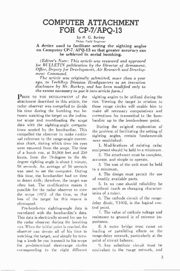
PRIOR TO THE DEVELOPMENT of the attachment described in this article, the radar observer was compelled to divide his time during the bombing run be-tween watching the target on the indica-tor scope and coordinating the scope data with the sighting-angle computa-tions needed by the bombardier. This compelled the observer to make contin-ual reference to the range-angle conver-sion chart, during which time his eyes were removed from the scope. The time of a bomb run, at 30,000 feet and 250 knots, from the 70-degree to the 46-degree sighting angle is about 1 minute, 50 seconds. An average of 50 seconds was used to set the computer. During this time, the bombardier had no time to detect drift; therefore, the target was often lost. The modification makes it possible for the radar observer to view the scope 100Y of the time, so that loss of the target for this reason is eliminated. Pre-bomb-run sighting-angle data is
correlated with the bombardier's data. This data is electrically stored for use by the radar observer during the bombing run. When the initial point is reached. the observer can devote all of his time to watching the target, and simply by turn-ing a knob he can transmit to his scope the predetermined slant-range circles corresponding to the eight different
sighting angles to be utilized during the run. Viewing the target in relation to these range circles will enable him to make all necessary computations and corrections for transmittal to the bom-bardier up to the bomb-release point.
During the original exploration of the problem of facilitating the setting of sighting angles, certain fundamentals were established: L Modifications of existing radar
equipment should be held to a minimum. 2. The attachment must be complete,
accurate, and simple to operate. 3. The cost of the unit must be held
to a minimum. 4. The design must permit the use
of readily available parts. 5. In no case should reliability be
sacrificed (such as changing character-istics of a tube). 6. The cathode circuit of the range-
delay diode, V1602, is the logical con-trol point. 7. The value of cathode voltage and
resistance to ground is of extreme im-portance. 8. A meter bridge must cause no
loading or paralleling effects on the range-delay network, particularly at the point of circuit balance. 9. Any substitute circuit must be
equivalent to the range network, and
3
is established by the position of the variable arm of the range-computer po-tentiometer, R1402. This arm position establishes a value of resistance to ground, which is part of the cathode bias network of V1602. A similar resist-ance network, permitting selection by means of a rotary switch, of one of eight adjustable potentiometers—RI to R8 inclusive—duplicates the condition set up by the computer, and is convert-ible to slant ranges or sighting angles. Correct adjustment is indicated by a zero reading on a zero-center meter, M1 (sensitivity button depressed), which is connected between the two circuits in a manner approximating a Wheatstone bridge. A point of circuit balance is reached by adjustment of the sighting-angle potentiometer arm until the me-ter reads zero (sensitivity button de-pressed), at which time no current will
must be powered from the same voltage source. 10. A distinct advantage must result
from utilization of the attachment.
FUNCTION
Function of the computer attachment is quite simple (see figure 1). A voltage
flow through the meter; thus, there are no loading or paralleling effects on the range-delay network.
INSTALLATION
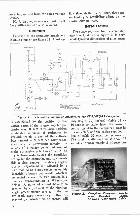
The space required for the computer attachment, shown in figure 2, is very small (present dimensions of attachment
. 011 COC O'S I
•200V
M VO
•44•011, I
0 • 21.0r
VC .
!
.00
".
004
•07 •••••• •
10 •
Of L:!":!01)f C.003
11.0.•
•
MVO
CC i f: r"
M IS
'CT
TA"
7
16.
•-•Nj
7 4!,
'
a rmit•ISTA .11 AS P O . 0000 Jalf• 01.00111. M O RD
,:oco It0000
•.:00
*****
Figure L Schematic Diagram of Attachment for CP-7/APQ-13 Computer
only 81/4 x 71/4 inches). Cable 32 (a 10-conductor cable from the azimuth control panel to the computer) must be disconnected, and the cables supplied in lieu of cable 32 must be reconnected. The total installation time is about 15 minutes. Approximately 2 minutes are
Figure 2.
1110 I, rig A rIA C W M/1T M M AL% 1 r4 435 moo' AIARCII Ail, CAL (fltr)
Complete Computer ment Mounted in Showing Connecting
Attach-Rack, Cable
4
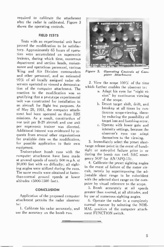
required to calibrate the attachment after the radar is calibrated. Figure 3 shows the operating controls.
FIELD TESTS
Tests with an experimental unit have proved the modification to be satisfac-tory. Approximately 65 hours of opera-tion were accumulated on supersonic trainers, during which time, numerous department and section heads, mainte-nance and operations personnel, various Wing and Air Division commanders and other personnel, and an estimated 95;4 of all locally assigned radar ob-servers operated or viewed a demonstra-tion of the computer attachment. The reaction to the modification was so gratifying that a prototype experimental unit was constructed for installation in an aircraft for flight test purposes. As of May 28, 1951, the computer attach-ment had been operated on three RBS missions. As a result, construction of one unit per B-29 aircraft and one unit per supersonic trainer was directed. Additional interest was evidenced by re-quests from several other organizations for available data on the modification, for possible application to their own equipment. Trainer-plane bomb runs with the
computer attachment have been made at ground speeds of nearly 600 m.p.h. at 30,000 feet with no difficulty; all sight-ing angles were utilized during the runs. The same results were obtained at faster-than-normal ground speeds at lower altitudes (5000-1500 feet).
CONCLUSION
Application of the proposed computer attachment permits the radar observer to: 1. Calibrate his radar accurately, and
use the accuracy on the bomb run.
w w $ • / I, ..,14/ 3 4‘
A rill4 4111
sa.1 •4/44/1i U ,'$9y s/ COM 01., IL AT TOCMPIE Pr f ••••OR 4414Pa • M ali Alf • •
Figure, 3. Operating Controls of Com-puter Attachment
2. View the scope 100̀A of the time which further enables the observer to:
a. Adapt his eyes for "night vi-sion" by continuous viewing of the scope.
b. Detect target shift, drift, and breakup at all times by con-tinuous scope-viewing, there-by reducing the possibility of target loss and bombing error.
c. Operate with lower gain and intensity settings, because the observer's eyes can adapt themselves to the viewing.
3. Immediately select the preset slant-range release point in the event of bomb-sight or auto-pilot failure prior to or during the bomb run (ref. SAC emer-gency SOP for AN/APQ-13). 4. Calibrate the preset sighting angles
in the event of failure of the meter cir-cuit, merely by superimposing the ad-justable slant range to be coincident with the selected slant range on the com-puter by visual reference to the scope. 5. Bomb accurately at all speeds
greater than normal, at all altitudes, and by use of numerous sighting angles. 6. Operate the radar in a completely
normal manner by selecting the NOR-MAL position of the computer attach-ment FUNCTION switch.
5

ELECTRONIC COMPUTERS PART III Basic Computer Circuits and Principles of Binary Addition
by Warren Kitter Technical Publications Department
The third of a series of articles discussing electronic computers. This article deals with the basic concepts of logical AND, OR, and NOT circuits, and the prin-
ciples of binary addition.
A DISTINCT ADVANTAGE Of modern elec-tronic computers is the ability of the electronic circuits to instantly switch the results of computation from one section of the computer to another, with-out any intermediate process of tran-scribing the data. To provide the switch-ing functions, three different types of switching circuits are used: logical AND, OR, and NOT circuits. The logical AND circuit, which is
shown in block-diagram form in figure 1, is designed to perform the computa-tional function implied by the word and (logical concept) as used in number re-lationships; for example, X and Y. As the name of the circuit indicates, an output pulse occurs at C only when in-put pulses appear at both A and B simultaneously.
Figure 1. Block Symbol AND Circuit
Figure 2 shows the schematic dia-gram of a typical logical AND circuit, which employs a tube of the dual-control-grid type. The circuit constants, as well as the positive voltage applied
for Logical
to the cathode, are of the proper values to bias the tube well below cutoff. The bias is great enough that a positive pulse arriving only on line A or on line B does not have sufficient amplitude to
Figure 2. Schematic Diagram of Logi-cal AND CIRCUIT
cause the tube to conduct. Therefore, for this condition there is no output pulse on line C. However, if pulses arrive simultaneously on both lines A and B, the tube is driven into conduc-tion and produces a positive pulse as an output on line C.
If the presence of a pulse is denoted by binary number 1 and the absence of a pulse by 0, the status of a logical
6
AND circuit for each set of input con- circuit for each set of input conditions ditions may be summarized as in Table I. may be summarized as in Table II.
Table I. Status of Logical AND Circuit for All Possible Input Conditions
A B C
0 0 0 1 0 0 0 1 0 1 1 1
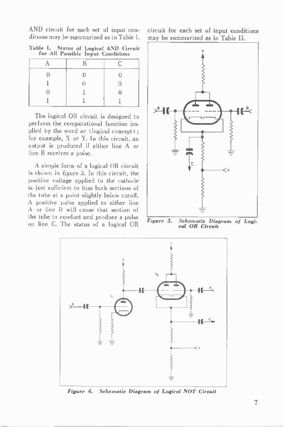
The logical OR circuit is designed to perform the computational function im-plied by the word or I logical concept I; for example, X or Y. In this circuit, an output is produced if either line A or line B receives a pulse.
A simple form of a logical OR circuit is shown in figure 3. In this circuit, the positive voltage applied to the cathode is just sufficient to bias both sections of the tube at a point slightly below cutoff. A positive pulse applied to either line A or line B will cause that section of the tube to conduct and produce a pulse on line C. The status of a logical OR
.---
Figure 3. Schematic Diagram of cal OR Circuit
Figure 4. Schematic Diagram of Logical NOT Circuit
Logi-
7
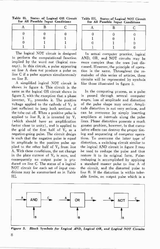
Table II. Status of Logical OR Circuit Table III. Status of Logical NOT Circuit for All Possible Input Conditions for All Possible Input Conditions
A B C
0 0 0 1 0 1 0 1 1 1 1 1
The logical NOT circuit is designed to perform the computational function implied by the word not (logical con-cept). In this circuit, a pulse appearing on line A does not produce a pulse on line C if a pulse appears simultaneously on line B. A simplified logical NOT circuit is
shown in figure 4. This circuit is the same as the logical OR circuit shown in figure 3, with the exception that a phase inverter, VI, precedes it. The positive voltage applied to the cathode of V2 is just sufficient to keep both sections of the tube cut off. When a positive pulse is applied to line B, it is inverted by V1 (which should have an amplification factor close to unity), and is applied to the grid of the first half of V2 as a negative-going pulse. The circuit design is such that the negative pulse is equal in amplitude to the positive pulse ap-plied to the other half of V2 from line A. With these conditions, the net change in the plate current of V2 is zero, and consequently no output pulse is pro-duced on line C. The status of a logical NOT circuit for each set of input con-ditions may be summarized as in Table
A B C
() 0 0 1 0 1 0 1 0 1 1 0
In actual computer practice, logics AND, OR, and NOT circuits may be more complex than the ones just dis-cussed. However, the principle of opera-tion is the same. Throughout the re-mainder of this series of articles, these circuits will be represented by symbols like those illustrated in figure 5.
In the computing process, as a pulse is passed through several computer stages, loss of amplitude and distortion of the pulse shape may occur. Ampli-tude distortion is not very serious, and can be overcome by simply inserting amplifiers at intervals along the pulse lines. Phase distortion presents a much greater problem, however, in that cumu-lative effects can destroy the proper tim-ing and sequencing of computer opera-tions. To overcome the latter type of distortion, a switching circuit similar to the logical AND circuit in figure 2 may be used to reshape the pulse and thus restore it to its original form. Pulse. reshaping is accomplished by applying a standard master pulse to line A of the circuit, and the distorted pulse to line B. If the distortion is within toler-able limits, an output pulse which is a
A 0.1AND co. A alOR Co. NOT Ca
Figure 5. Block S'Inbols for Logical AM), Logical OR, and Logical NOT Circuits
8

duplicate of the master pulse will appear on line C. Another circuit that must be con-
sidered before the block diagram of an adding system can be discussed is the delay line. By definition, a delay line is simply
an artificial transmission line, in which lumped values of inductance and capaci-tance replace the distributed inductance-capacitance values present in a normal transmission line. If AB in figure 6 represents a con-
ventional transmission line, it can be seen that some finite time is required for a pulse applied to point A to travel to the opposite end of the line at point B. It will take some fraction of that time, of course, for the pulse to travel to any intermediate point between A and B.
0
A
Figure 6. Schematic Representation of Conventional Transmission Line
An artificial transmission (or delay) line can be formed from inductors and capacitors arranged as shown in figure 7. If the proper values are selected, the delay time between each section of the line can be made equal to a pulse in-terval. Thus, if a pulse is started along the line at A, it will arrive at B after a delay of one interval; at C after a delay
A oT T T T I XAMMII,
Figure 7. Schematic Representation of Artificial Transmission (De-lay) Line
of two intervals; at D after a delay of three intervals; and at E after a delay of four intervals. The line can be ex-tended, by adding sections, to introduce any desired amount of delay between the time a pulse is applied to the line, and the time it reaches a given delay. line tap. In this discussion, a delay line will be represented by the symbol shown in figure 8. The number appearing in the block indicates the number of delay intervals introduced into the circuit.
3 DELAY
Figure 8. Block Symbol for Computer Delay Line
BINARY ADDITION
Before a discussion of binary addi-tion is begun, three important terms that are encountered in any process of addition should be defined. These terms are: Addend—the number to be added. Augend—the number to which the addend is added.
Carry—the number of tens, hundreds, or thousands, etc.. resulting from the addition of the digits of one order and added to the digits of the next higher order, on the left.
Binary* addition is relatively simple in that there are only four possible com-binations of an augend and addend consisting of one-place numbers, as com-pared to 100 combinations in the decimal system. These combinations are: 0 ± 0, 1 + 0,0 ± 1, and 1 + 1. Of these, the first three combinations may be added directly: 0 ± 0 = 0, 1 ± 0 = 1, 0 ± 1 = 1. In adding binary 1 ± 1, we must increase beyond the limits of the highest digit ( 1) in the
° Binary notation was discussed in the article, Electronic Computers—Part I.
9
binary system. To do this, we use the rule given in the first article (Part I) of this series: substitute the lowest digit in the system for the highest digit, and increase the digit in the next higher place (order) by one. This means that the binary sum of 1 + 1 is 0 with a carry of 1. The carry must be added to the digits in the next order to the left. In order that the reader may become familiar with the binary addition com-binations, a list of the combinations is given below in Table IV:
Table IV. Binary Addition Combinations
AUGEND ADDEND SUM CARRY
0
1
0 1
0
0
1
1
0
1
1
0
0
0
0
1
To further illustrate binary addition, consider 0000101 + 0000011, ( 5 + 3). The digits in each order of the binary numbers must be added separately start-
3rd-order digits: 1 + 0 + 1 (carry) = 0 carry 1
4th-order digits: 0 -I- 0 + 1 (carry) =1
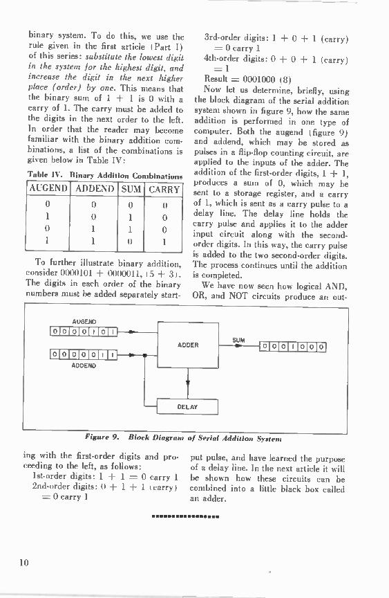
Result = 0001000 (8) Now let us determine, briefly, using
the block diagram of the serial addition system shown in figure 9, how the same addition is performed in one type of computer. Both the augend (figure 9) and addend, which may be stored as pulses in a flip-flop counting circuit, are applied to the inputs of the adder. The addition of the first-order digits, 1 + 1, produces a sum of 0, which may be sent to a storage register, and a carry of 1, which is sent as a carry pulse to a delay line. The delay line holds the carry pulse and applies it to the adder input circuit along with the second. order digits. In this way, the carry pulse is added to the two second-order digits. The process continues until the addition is completed. We have now seen how logical AND,
OR, and NOT circuits produce an out-
Figure 9. Block Diagram of Serial Addition System
ing with the first-order digits and pro-ceeding to the left, as follows: 1st-order digits: 1 ± 1 = 0 carry 1 2nd-order digits: 0 + 1 ± 1 (carry) = 0 carry 1
put pulse, and have learned the purpose of a delay line. In the next article it will be shown how these circuits can be combined into a little black box called an adder.
10

IMPROVEMENTS IN THE NBS PRIMARY STANDARD OF FREQUENCY Some details of modifications made recently in the primary standard of frequency maintained by the
National Bureau of Standards.
(Editor's Note: The information contained in this article was supplied by the National Bureau of Standards, U. S. Dept. of Commerce, and appears here through the courtesy of that agency.)
k CCOMPANYING THE MAINTENANCE of tile Nation's primary standard of fre-quency is a continuing investigation by the National Bureau of Standards of methods for improving the constancy and reliability of the standard. Some modifications incorporated within the last few years include the use of res-onator crystals to sustain the accuracy of the standard, more sensitive and re-liable temperature controls, and precise clock mechanisms to monitor time sig-nals. The use of new and improved components has resulted in a reduction in the number of replacement parts, and represents a considerable saving of time normally required for preventive-main-tenance procedures.
The NBS primary standard of fre-quency is the foundation upon which are based all time and frequency trans-missions from the Bureau's radio broad-casting stations WWV, in Beltsville, Maryland, and WWVH, Maui, Territory of Hawaii.* From these stations, stand-ard radio frequencies of 2.5, 5, 10, 15. 20, and 25 mc. are transmitted continu-ously, night and day, with accuracies of two parts in 100 million. Two standard audio frequencies, 600 and 440 cycles 'the standard musical pitch, A above middle C) are broadcast on all of the radio frequencies, and every 5 minutes are interrupted for intervals of one mm-
For additional information, see "Standard Frequencies and Time Signals from W WV and W WVH," NBS Letter Circular LC 1009.
ute. A pulse of 0.005-second duration occurs on each carrier frequency at intervals of one second. The time inter-vals, as transmitted, are accurate within 7_17 (two parts in 108 ± one micro-second). An announcement of radio-propagation conditions, pertinent only to transmission paths in the North At-lantic area, is broadcast in code on each of the standard radio frequencies.
The National Bureau of Standards' primary standard of frequency consists of nine crystal-controlled oscillators and eight quartz-crystal resonators. Three of the oscillators are located at the Belts-ville installation of WWV—one acting as the main oscillator for all of the transmitters, the second as the standby, and the third as a spare. The remaining six oscillators and the eight quartz-crystal resonators are maintained in the Bureau's Washington laboratories. All of the crystal-controlled oscillators are kept in continuous operation and the best ones- — those having the least amount of deviation from 100 kc. for the immediately preceding six-month period or longer—are the units from which the standard frequency is deter-mined.
The oscillators are controlled by spe-cially made GT-cut quartz crystals; the resonant frequency of each crystal is 100 kc. In examining the crystals, it has been observed that generally their per-formance curves (frequency vs. ampli-tude) have a flat region within which
11

the crystal frequency is relatively con-stant. When the driving current reaches a value of about 150 microamperes, the frequency decreases sharply. In view of this fact, the driving current applied to the crystal units of the newer NBS os-cillators is less than 100 microamperes. A decided improvement in performance occurs and is especially evident when compared to the older oscillators with driving currents of over 500 micro-amperes. Increased short-time stability and over-all reliability have also been achieved.
The eight resonator crystals have been part of the frequency standards for about one and a half years. Each resonator's frequency is used in the analysis of the accuracy and constancy of the other nine oscillators. All eight crystals, each also with a resonant fre-quency of 100 kc., are installed in a
single temperature-controlled oven. They do not incorporate additional compo-nents such as tubes, resistors, or capaci-tors. They are not driven continuously, but are used only once a day as part of a balanced-bridge network for compari-son with one of the standard oscillators. Furthermore, the current driving the crystals is only 10 microamperes.
Once a day, the value of each resona-tor crystal and each standard oscillator is determined, using the system shown in figure 1. First, a precision variable oscillator is adjusted to the frequency of one of the resonators. The variable oscillator is then compared to one of the standard oscillators, and the beat, or difference, frequency is counted on an electronic frequency counter with a precision of the order of parts in 10'°. The variable oscillator is readjusted to the second resonator crystal and again
PRIMARY STANDARDS NOS 1,2,3
PRIMARY STANDARDS NOS 4-8
PRIMARY STANDARD NO. 9
PRIMARY 1 RESONATORS NOS. 1-8
DIVIDER (each unit)
DIVIDER
CLOCK (each unit)
TRANSMITTER
WWV
I W W V I RECEIVER
CHRONOGRAFTH1
AMPLIFIER
DISTRIBUTION -• AMPLIFIER -•
DISTRI BUTION1-• AMPLIFIER 1-•
DISTRIBUTION AMPLIFIER
-• -•
RE MONITOR
Figure 1. Block Diagram ol the NBS Primary Standard of Frequency The primary standard is composed of nine crystal-controlled oscillators and eight resonator crystals. Three of the oscillators, located at the Bti radio station wwv in Beltscille. Maryland, control the transmission of the standard frequencies and time signals. The remaining six oscillators are installed in the Bureau's Washington laboratories. The time signals dericed from these oscillator• are continuously moni-tored by a spark chronograph and chronoscope that measures time differences as small as 20 millionths of a second. The time and frequency signals are also fed into dis-tribution amplifiers and over wire lines for use by the scientific staff within the
Washington laboratory.
12
compared to the same standard oscilla-tor. The difference frequency between these two oscillators is again recorded. This procedure is continued until data are available indicating the amount of frequency deviation present between the standard oscillator and each of the res-onator crystals. One of the remaining eight oscillators is used as a reference against which all of the other oscillators are compared. Thus, data are available for precisely determining any changes, relative to the system, which may occur in any oscillator or resonator in the system. The reference oscillator is also in-
strumental in obtaining a continuous record of the frequencies of the three standard oscillators at the WWV instal-lation. Automatically, the main, stand-
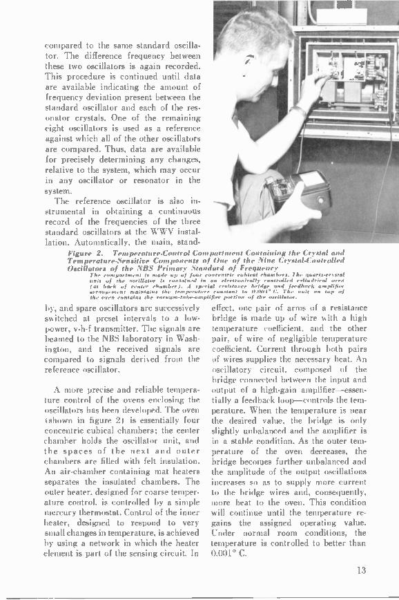
Figure 2. Temperature-Control Compartment Containing the Crystal and Temperature-Sensitive Components of One of the Nine Crystal-Controlled Oscillators of the NBS Primary Standard of Frequency
The compartment is made up of four concentric cubical chambers. The quarts-crystal unit of the oscillator is contained in an electronically controlled cylindrical oven (as back of center chamber). I special resistance bridge and feedback amplifier arrangement maintains the temperature constant to 0.00I° C. The unit on top of the oven contains the vacuum-tube-amplifier portion of the oscillator.
by, and spare oscillators are successively switched at preset intervals to a low-power, v-h-f transmitter. The signals are beamed to the NBS laboratory in Wash-ington, and the received signals are compared to signals derived from the reference oscillator.
A more precise and reliable tempera-ture control of the ovens enclosing the oscillators has been developed. The oven I shown in figure 2) is essentially four concentric cubical chambers; the center chamber holds the oscillator unit, and the spaces of the next and outer chambers are filled with felt insulation. An air-chamber containing mat heaters separates the insulated chambers. The outer heater, designed for coarse temper-ature control, is controlled by a simple mercury thermostat. Control of the inner heater, designed to respond to very small changes in temperature, is achieved by using a network in which the heater element is part of the sensing circuit. In
effect, one pair of arms of a resistance bridge is made up of wire with a high temperature coefficient, and the other pair, of wire of negligible temperature coefficient. Current through both pairs of wires supplies the necessary heat. An oscillatory circuit, composed of the bridge connected between the input and output of a high-gain amplifier—essen-tially a feedback loop—controls the tem-perature. When the temperature is near the desired value, the bridge is only slightly unbalanced and the amplifier is in a stable condition. As the outer tem-perature of the oven decreases, the bridge becomes further unbalanced and the amplitude of the output oscillations increases so as to supply more current to the bridge wires and, consequently, more heat to the oven. This condition will continue until the temperature re-gains the assigned operating value. Under normal room conditions, the temperature is controlled to better than 0.001° C.
13
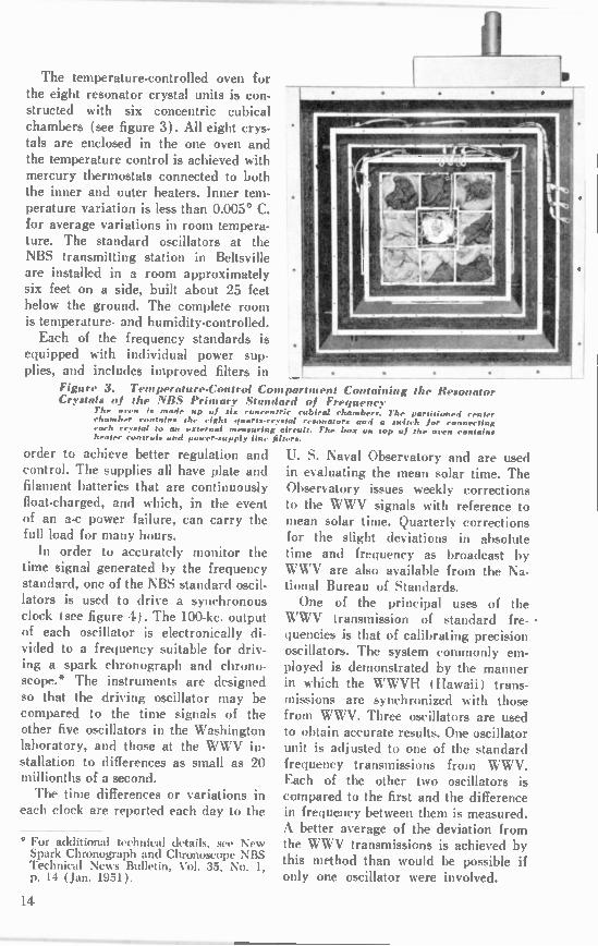
The temperature-controlled oven for the eight resonator crystal units is con-structed with six concentric cubical chambers (see figure 3). All eight crys-tals are enclosed in the one oven and the temperature control is achieved with mercury thermostats connected to both the inner and outer heaters. Inner tem-perature variation is less than 0.005° C. for average variations in room tempera-ture. The standard oscillators at the NBS transmitting station in Beltsville are installed in a room approximately six feet on a side, built about 25 feet below the ground. The complete room is temperature- and humidity-controlled. Each of the frequency standards is
equipped with individual power sup-plies, and includes improved filters in
Figure 3. Temperature-Control Compartment Containing the Resonator Crystals of the NBS Primary Standard of Frequency
7h.. oren is made up of six concentric cubical chambers. The partitioned center chamber contain• the eight quarts-crystal resonators and a switch for connecting each crystal to an external no ing circuit. The box on top of the oren contains heater controls and power-supply line filters.
order to achieve better regulation and control. The supplies all have plate and filament batteries that are continuously float-charged, and which, in the event of an a-c power failure, can carry the full load for many hours. In order to accurately monitor the
time signal generated by the frequency standard, one of the NBS standard oscil-lators is used to drive a synchronous clock (see figure 4). The 100-kc. output of each oscillator is electronically di-vided to a frequency suitable for driv-ing a spark chronograph and chrono-scope.* The instruments are designed so that the driving oscillator may be compared to the time signals of the other five oscillators in the Washington laboratory, and those at the WWV in-stallation to differences as small as 20 millionths of a second. The time differences or variations in
each clock are reported each day to the
° For additional technical details, see New Spark Chronograph and Chronoscope NBS Technic-al News Bulletin, Vol. 35, No. 1, p. 14 ( Jan. 1951).
U. S. Naval Observatory and are used in evaluating the mean solar time. The Observatory issues weekly corrections to the WWV signals with reference to mean solar time. Quarterly corrections for the slight deviations in absolute time and frequency as broadcast by WWV are also available from the Na-tional Bureau of Standards. One of the principal uses of the
WWV transmission of standard fre- • quencies is that of calibrating precision oscillators. The system commonly em-ployed is demonstrated by the manner in which the WWVH (Hawaii) trans-missions are synchronized with those from WWV. Three oscillators are used to obtain accurate results. One oscillator unit is adjusted to one of the standard frequency transmissions from WWV. Each of the other two oscillators is compared to the first and the difference in frequency between them is measured. A better average of the deviation from the WWV transmissions is achieved by this method than would be possible if only one oscillator were involved.
14
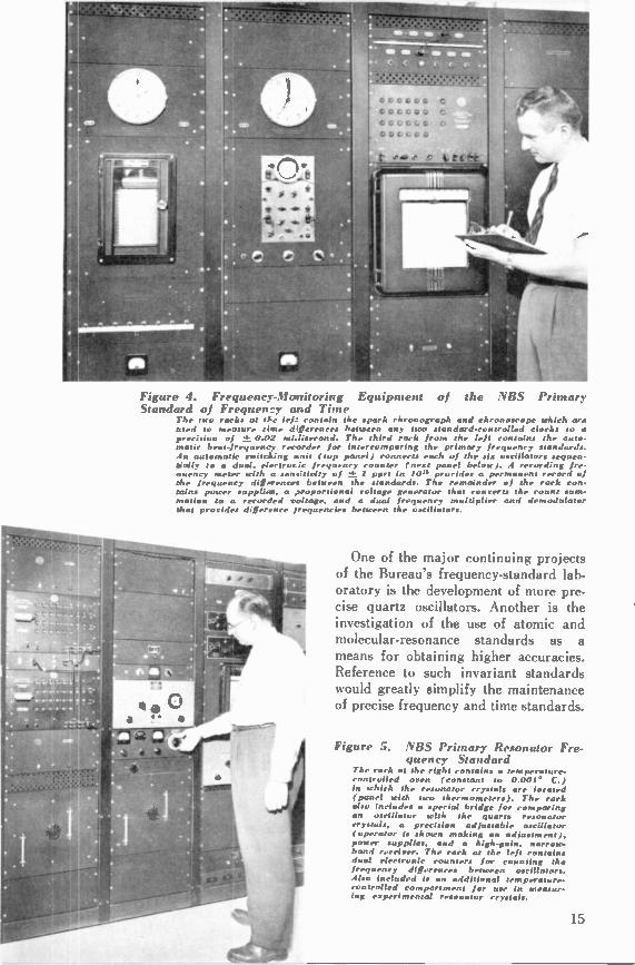
Figure 4. Frequency-Monitoring Equipment of the NBS Primary Standard of Frequen:7 and Time
The two racks at the lef.: contain the spark chronograph and chronoscope which are used to measure time differences between any two standard-controlled clocks to a preeigion of ± 0.02 mi.lisecond. The third rack from the left contains the auto-matic beat-frequency recorder for intercom paring the primary frequency standards. An automatic switching snit (top panel) connects each of the six oscillators sequen-tially to a dual, electrorie frequency counter (next panel below). A recording fre-auency meter with a sensitivity of ± I part in 10'° provides a permanent record of the frequency diffxrenres between the standards. The remainder of the rack con-tains power supplies, a 2roportional voltage generator that converts the count sum-mation to a recorded voltage, and a dual frequency multiplier and demodulator that provides difference frequencies between the oscillators.
One of the major continuing projects of the Bureau's frequency-standard lab-oratory is the development of more pre-cise quartz oscillators. Another is the investigation of the use of atomic and molecular-resonance standards as a means for obtaining higher accuracies. Reference to such invariant standards would greatly simplify the maintenance of precise frequency and time standards.
Figure 5. NUS Primary Resonator Fre-quency Standard
The rack at the right contains a temperature-controlled oven (constant to 0.001 ° C.) in which the resonator crystals are located (panel with two thermometers). The rack also includes a special bridge for comparing an oscillator with the quarts resonator crystals, a precision adjustable oscillator (operator is shown making an adjustment), power supplies, and a high-gain, narrow-band receiver. The rack as the left contains dual electronic counters for counting the frequency diff ccc between oscillators. Also included is an additional temperature-controlled compartment for use in m ing experimental resonator crystals.
15
GUIDED MISSILES by Merle E. McDougall PhiIca Field Enginoor
A summary of available declassified information on the characteristics and capabilities of modern guided missiles. (Editor's Note: All material contained in this article has previously appeared in unclassified or declassified publications, extract copies of which are on file in the BULLETIN editorial office.)
p ROGRESS IN THE GUIDED-MISSILE FIELD
has been phenomenal since World War II. At that time, the only guided missiles in existence were the German V-2 rocket and the V-1 buzz bomb which was used against London during the latter days of the war. These missiles had relatively short range (150 to 250 miles), and their accuracy was poor (approximately 8 miles error in 150 miles). About 15,000 V-1 and 2500 V-2 missiles were fired during World War II by Germany. Since that time the countries of the world have been spending large amounts in both manpower and money to de-velop the guided missile into a tactical weapon. As a result, the modern guided missile can fly at a speed several times that of the fastest airplane, and hunt out and destroy an aircraft or deliver a war-head on a distant target with quarter-mile accuracy. The mind can visualize missiles of the future that will do the work of artillery and long-range aircraft, and do it better, carrying either regular explosives or atomic bombs. Guided missiles are of necessity very complex; scientists and engineers who are en-gaged in propulsion and guidance sys-tem developtnent must draw on many fields of knowledge, including aerody-namics, electronics, propulsion, optics, and many others. Guided missiles can be divided into a
number of categories according to their tactical purpose; such as air-to-air (launched from an airplane toward an airborne target), air-to-surface, surface-to-air, and surface-to-surface.
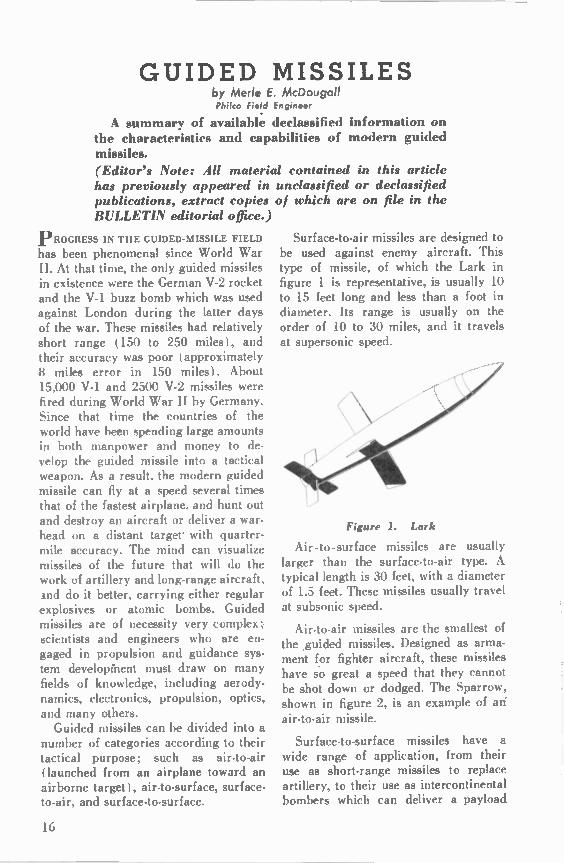
Surface-to-air missiles are designed to be used against enemy aircraft. This type of missile, of which the Lark in figure 1 is representative, is usually 10 to 15 feet long and less than a foot in diameter. Its range is usually on the order of 10 to 30 miles, and it travels at supersonic speed.
Figure L Lark
Air-to-surface missiles are usually larger than the surface-to-air type. A typical length is 30 feet, with a diameter of 1.5 feet. These missiles usually travel at subsonic speed.
Air-to-air missiles are the smallest of the .guided missiles. Designed as arma-ment for fighter aircraft, these missiles have so great a speed that they cannot be shot down or dodged. The Sparrow, shown in figure 2, is an example of an air-to-air missile.
Surface-to-surface missiles have a wide range of application, from their use as short-range missiles to replace artillery, to their use as intercontinental bombers which can deliver a payload
16

halfway around the world with the ac-curacy of a conventional bomber and without the risk to men. A typical long-range surface-to-surface missile is about the length of a V-2 (46 feet long), but is slimmer and presumably has much greater range.
Figure 2. Sparrow
The United States has several test sites for guided missiles, of which the three major sites are White Sands, New Mexico; Point Mugu, California; and Banana River, Florida. The largest of these firing ranges is Banana River, which spreads over an area of 100,000 square miles from Florida to Puerto Rico. At present, this range is limited to a distance of 1000 miles, but, if nec-essary, it can be extended into the South Atlantic to a maximum distance of 5000 miles. Upon final completion, the range will have a launching site at Cape Canaveral, Florida, and eight instru-mentation stations along the 1000-mile course to Puerto Rico.
GUIDANCE SYSTEMS
For a missile to be a tactical weapon, its movements must be controllable, either before it gets into the air or while it is on its way to the target; con-trol of the missile's movements is termed "guidance." Many types of guidance systems are possible, each with its ad-vantages and disadvantages. All of these types will be discussed in the following paragraphs. PRESET SYSTEM: As the name of
this guidance system implies, all of the functions that are to be performed
within the missile during flight are set upon a programmer before launching. For instance, the V-2 was launched ver-tically, and after it ascended straight up for a certain period of time a program-mer caused it to tip toward the horizon-tal and commence its trajectory toward the target. After another predetermined time period, other functions were per-formed, such as cutting the fuel off and causing the missile to dive into the tar-get area. If unforeseen elements arose, such as changes in wind direction and variations in atmospheric pressure, they could not be compensated for by the missile guidance system; therefore, the probable error of the preset missile was large.
COMMAND SYSTEM: Command guidance can be used in surface-to-air missiles designed for antiaircraft use. When an enemy aircraft is located in the vicinity, the missile is launched, and both the missile and the target are viewed on a radar screen. The missile operator has control of the missile from the ground by way of radio. The opera-tor's duty is to guide the missile close to the aircraft while watching both on the radar scope. The missile contains a proximity fuze which will explode the missile when it comes in the close vicin-ity of the aircraft. This method of guidance is simple, but brings into play the human element, which with high-speed aircraft is not sure. Since the missile is radio-controlled, counter measures, such as the radiation of radio-frequency noise by enemy jamming equipment, can be used to prevent the commands from reaching the missile. Proper missile antenna design and high signal strength will make jamming more difficult.
BEAM-RIDER SYSTEM: This type of guidance system is primarily used in antiaircraft missiles. The target is tracked by radar, which produces a nar-row beam of radar-frequency energy be-
17

tween the radar transmitter and the target. The missile is fired into the beam and follows it for a certain dis-tance; then computers in the missile cause the missile to lead the target, like a hunter leads a duck, so as to produce a collision course which will destroy the missile and the target.
SEEKER SYSTEM: Missiles using the seeker guidance system can be di-vided into two classifications: active, and passive. Active seeking missiles con-tain a radar transmitter and receiver. The missile is steered from the ground to the target vicinity, after which the missile radar takes over, sends out ra-dar pulses, and steers the missile toward anything solid enough to reflect the ra-dar echoes back to the missile radar receiver. Passive seeking missiles have sensitive elements which pick up such radiations from the target as light or heat, and steer the missile to the target. The seeker becomes more accurate as it approaches the target, and if the tar-get changes course, the missile also changes course and produces a collision. Seeker missiles can be made to travel at supersonic speed and cannot be evaded or dodged.
TERRESTRIAL SYSTEM: The ter-restrial system of guidance, generally useful for surface-to-surface missiles, makes use of the earth's phenomena to keep it on a predetermined course. Such phenomena as the earth's gravitational, electric, and magnetic fields, and the at-mospheric density can be used. An ex-ample of a terrestrial reference missile is the German V-1, which used a mag-netic compass to keep it on course, an altimeter to keep it at the proper alti-tude, and an airlog to determine dis-tance traveled, so as to keep the missile on the predetermined course and cause it to go into its terminal dive at the proper time and place.
CELESTIAL SYSTEM: This guid-ance system is useful for long-range-
bombardment missiles, and is based on the method used by navigators in "shooting" two stars to determine pres-ent position. Automatic star-tracking telescopes and a recording of the pre-determined course are contained in the missile. The present position of the mis-sile as determined by the telescopes is compared periodically with the position at which the missile should be. Any deviation from the correct position re-sults in the production of error data, which cause the steering mechanism to bring the missile back to its proper course. The accuracy of this type of guidance system is as good at the target site as at the launching site. No counter-measures can be effective against a mis-sile incorporating a celestial guidance system unless faster missiles are de-signed to intercept it. The system is limited primarily to night-time opera-tion, but this is not too much of a dis-advantage when it is used on supersonic missiles; the course can be flown during a time when the background intensity of the sky is low.
RADIO-NAVIGATION SYSTEM: The radio-navigation guidance system makes use of a type of navigation known as LORAN. The missile contains a radio receiver which receives signals sent simultaneously from two fixed ground transmitters, and the missile measures the time delay between the times of reception of the two signals. Before the missile is launched, its elec-tronic brain is "instructed" as to the correct time delays for the predeter-mined course. If the missile deviates from the correct path, the time delay becomes greater or less than the pre-determined value, and the missile is guided back to the correct course. This type of guidance system is accurate, but is subject to interference and enemy electronic countermeasures. INERTIAL SYSTEM: The inertial
guidance system employs devices called accelerometers, which are sensitive to
18
accelerations. These accelerometers are installed in the missile, and a flight plan containing all known accelerations along the correct flight course is fed into the guidance system before the missile is launched. If accelerations not contained in the flight plan (such as those due to wind) take place, the accelerometers record and doubly integrate them, to obtain the distance that the missile has traveled off course. Corrections are then fed to the steering mechanism to put the missile back on its predetermined course. This guidance system is entirely self-contained, and therefore cannot be jammed. Its only drawback is the com-plexity of the missile equipment. TELEVISION SYSTEM: For televi-
sion guidance of a missile, a small tele-vision transmitter is installed in the nose of the missile. This equipment transmits a television picture of the area ahead of the missile to the missile operator, who controls the missile from a "mother" airplane or ground station. Examples of this type of missile are the Navy's F6F Grumman Hellcats which were used in Korea as television-controlled missiles. The control airplanes were Douglas AD-2's. which stayed well out of range while the missile airplanes flew into the target. Television guidance is good up to ap-proximately 500 miles from the control site.
PROPULSION SYSTEMS Two basic types of propulsion systems
are available for missile use—rockets and jet engines. The rocket is a self-contained unit which carries both the fuel and the oxidizer, and therefore can fly out of the earth's atmosphere. An-other advantage of the rocket is that its top speed is unlimited. Rockets can be divided into two classes: the solid-propellant rocket and the liquid-propel-lant rocket. The solid-propellant rocket is very simple in construction and may be stored easily in the field until needed one of the popular solid propellants at present is potassium perchlorate in as-phalt). Its disadvantages are that the
combustion chamber must be heavy and large, and its burnout time is short. The liquid-propellant rocket can be turned on and off during flight and has a much longer range than the solid-propellant rocket. The disadvantage of the liquid-propellant rocket is the problem of handling and storing the fuel. The liquids are sometimes acids, such as nitric acid, or liquid gases such as liquid oxygen, which must be kept at very low temperatures ( —200 de-grees F.). The jet engine, the other propulsion
system, generally exhibits less thrust than the rocket, although it has a lower rate of fuel consumption, which makes it applicable for long-range use. The jet engine is more costly than the rocket, but a suc,essful mission would justify the cost. Jet engines usually use kero-sene or gasoline as a fuel. The ceiling of the jet engine is limited, as it must have oxygen for operation.
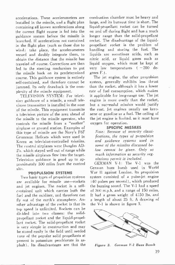
SPECIFIC MISSILES Note: Because of secant) classi-fications, the types of propulsion and guidance systems used in some of the missiles discussed be-low cannot be given. Only as much information as security reg-ulations permit is included. GERMAN V-1: The V-1 was the
German buzz bomb used in World War II against London. Its propulsion system consisted of a pulse-jet engine ( 40 pulses per second), which produced the buzzing sound. The V-1 had a speed of 360 m.p.h. and a range of 150 miles. It had a gross weight of 4750 lbs. and a length of about 25 ft. A drawing of the V-1 is shown in figure 3.
Figure 3. German V-1 Buzz Bomb
19

GERMAN V-2: The guidance system of the V-2 was preset before launching and could not be corrected after launching. The V-2 had a top speed of 3750 m.p.h. Its power plant was a liquid-propellant rocket, using liquid oxygen and ethyl alcohol, which gen-erated 50,000 pounds thrust (equivalent to 500,000 horsepower). Its range was approximately 250 miles. The V-2 had a gross weight of 28,400 pounds and carried a 2000-pound warhead, which contained a low-force explosive. The aerodynamic friction at 3750 m.p.h. pro-duced so much heat that a high explo-sive would have been detonated before flight termination. In its 65 seconds of powered flight, the V-2 consumed 20,000 pounds of fuel.
VIKING: The Viking, shown in fig-ure 4, is primarily a test vehicle and a sounding rocket. It is 45 ft. long and has a diameter of about 21/, ft. The Viking has been launched at White Sands, New Mexico, to investigate con-ditions in the upper atmosphere. It is powered by a liquid-propellant rocket, which has driven it at a top speed of 5000 m.p.h. and to an altitude of 200 miles. The Viking weighs 10,000 lbs., and can carry a payload of 1400 lbs. It is launched vertically. Heading errors are detected by gyroscopes, and the re-sultant signals are fed to servos which operate vanes to correct the error head-ing. Roll-control error signals are pro-duced in the same way, and are used to control exhaust ducts and tabs to cor-rect errors. Aluminum alloys are used for all surface areas of the missile ex-cept the nose and leading edges of the fins, where high temperatures are pro-
Of •
C Off , ROL
Figure 4. Viking. Showing Internal Com par t tit entation
duced by aerodynamic heating. Stain-less steel is used for these high-tempera-ture areas.
TERRIER: The Terrier is a surface-to-air missile developed for the Navy Bureau of Ordnance and soon to go into large-scale production at Convair. It is slated for fleet use during the next few years.
MATADOR: The Matador is a sur-face-to-surface missile designed for medium-range bombardment. The Mata-dor, figure 5, is about 30 ft. long, is jet and rocket propelled, and has a top speed of over 1000 m.p.h.
Figure 5. B-6I Matador
According to reports, it is radar-controlled and has a 500-mile range. The Matador is currently being tested at Banana River, Florida.
SPARROW: The Sparrow, shown in figure 2, is a tiny air-to-air Navy mis-sile on which production is to be handled by Sperry. It is intended for fighter use against bombers.
NIKE: The Nike, which is designed for antiaircraft defense, has a solid. propellant booster and a liquid-fuel rocket. It is being jointly developed by Bell and Douglas.
CORPORAL E: The Corporal is a 40-ft. Army missile, designed for use against ground installations. It weighs 12,000 lbs. and has a range of 100 miles. It is supersonic, with a speed of four to five times the speed of sound, and is reported to have an accuracy of 500 ft. at a range of 100 miles.
20

SNARK: The Snark is a surface-to-surface missile, designed for long-range bombardment; it is being developed by Northrup.
OERLIKON: The Oerlikon is a Swiss antiaircraft missile. The missile is about 16.5 ft. long and 1.5 ft. in diameter, and weighs about 550 lbs. with a warhead of approximately 45 lbs. The propulsion system is a liquid-fuel rocket using nitric acid, with a burning time of 6 seconds and a top altitude of 66,000 ft. The guidance system is of the beam-rider type with a maximum control range of about 12 miles.
AEROBEE: The Aerobee is a free-flight sounding rocket, used for investi-gation of the upper atmosphere. It is 20 ft. long and 15 in. in diameter, and uses a liquid ,rocket with a JATO booster to propel its 150-lb. payload to a height of 80 miles.
LARK: The Lark, shown in figure 1, is an antiaircraft missile which is pro-pelled by a liquid-fuel rocket using red fuming nitric acid and aniline. In this missile, the fuel and oxidizer are forced into the rocket engine by bottles of compressed air at a pressure of 500 pounds per square inch. The Lark is 173 in. long. Its guidance system uses radar homing, which becomes more accurate as the missile approaches its target. In tests, the Lark has been fired at the Naval Air Missile Test Center, Point Mugu, California, and from the Norton Sound, a seaplane tender used for missile firings. The Lark is launched from a zero-length launcher (the launcher is no longer than the missile).
WAC CORPORAL: The WAC Cor-poral, which has a weight of 1000 lbs., has been used as a high-altitude sound-ing rocket. For high-altitude use, the missile is attached to the nose of a V-2. The two missiles are then launched as a two-stage rocket, with the V-2 dropping away at an altitude of 20 miles and a speed approaching 5000 m.p.h. The
highest altitude reached so far with a two-stage rocket of this type has been 250 miles.
FIREBIRD: The Firebird, shown in figure 6, is produced by Ryan. It is an air-to-air weapon, 10 ft. long and 6 in. in diameter, with a rocket motor. A radar homing device is used to steer the missile to the target.
Figure 6. Firebird
RUSSIAN DEVELOPMENTS: The Russians have been using the former German rocket base at Peenemunde as a test site. At present they are known to be working on four different missiles. One is the former German Wasserfall antiaircraft rocket, which was, and probably still is, a rocket-propelled mis-sile using nitric acid and aniline as propellants. The German missile was 251/2 ft. long and 3 ft. in diameter, with a gross weight of 8500 lbs. Maximum speed was around Mach 3. Another missile that the Russians are
working on is the A-9, a winged version of the V-2. The A-9 was developed by the Germans in an attempt to get more range out of the V-2. It was simply a V-2 to which a set of swept-back wings had been welded. Only three of the A-9 missiles were fired by the Germans; it was hoped that their range would be 500 miles. The dream of Germany was the use of the A-9 as the second stage of a two-stage rocket for the bombing of New York. The A-5 rocket is a half-size V-2
which is used by the Russians for ex-
21
perimentation. As developed by the Germans, it was rocket-propelled by a so-called "cold" rocket, which used the decomposition of hydrogen peroxide to furnish superheated steam as the ex-haust gas.
A missile of the V-1 or Matador type is also being used at Peenemunde; six new zero-length launching ramps have been built for a missile of this type.
What's
Your
Answer?
CONCLUSION From the preceding discussion some
idea can be gained of the development, use, and future of guided missiles. In addition to their use by world powers as deadly, precision-controlled weapons of war, there is the possibility that one day guided missiles will provide the means for peacetime interplanetary travel, which has been the dream of mankind for many centuries.
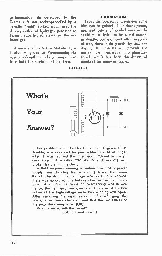
This problem, submitted by Philco Field Engineer G. P. Rumble, was accepted by your editor in a fit of anger when it was learned that the recent "Jewel Robbery" case (see last month's "What's Your Answer?") was broken by a shipping clerk. A field engineer running a routine check of a power
supply (see drawing for schematic) found that even though the d-c output voltage was essentially normal, there was no a-c voltage between the two rectifier plates (point A to point B). Since no overheating was in evi-dence, the field engineer concluded that one of the two halves of the high-voltage secondary winding was open. After removing the input power and discharging the filters, a resistance check showed that the two halves of the secondary were intact (OK). What is wrong with the circuit?
(Solution next month)
22
A REDISCOVERY OF LONG-STANDING ARITHMETICAL TECHNIQUES
by Mark Flomenhoft Pt.!. Research Division
k discussion of the writer's rediscovery of an old but useful method of checking the accuracy of arithmetical operations based upon the principle of "casting out nines," supplemented by a discussion of the divisibility of numbers and of methods of multiplying and squar-ing numbers rapidly by the use of well-known algebraic
laws.
W H ILE BROWSING THROUGH AN AL-
GEBRA BOOK recently, the writer en-countered a long-standing theorem of numbers that struck home with thought-provoking impact. This theorem is the basis of the principle of "casting out the nines" as a means of checking arith-meiical operations. Since the rule is re-puted to be well-known, many readers probably are already familiar with it. Indeed, it would seem that since the first edition of the aforementioned text ap-peared in 1888, the principle should now be a commonplace among people who perform the innumerable calcula-tions required in any technical field. Nevertheless, the writer was completely ignorant of the principle. This article, therefore, is offered to
those who are in the same plight as the writer had been. Because numbers and the arithmetical processes are the pri-mary tools of scientific activity, it is unthinkable for people who continually perform calculations to remain unaware of the time-worn rules for checking ac-curacy. In the discussion immediately following, these rules and various other p'roperties of numbers will be stated without proof. For those readers who would like to justify the validity of this information, an appendix of mathemat-ical proofs based on standard texts has also been included. CHECKING MULTIPLICATION t,ince multiplication is one of the
more arduous arithmetical operations,
let us consider it first. The best way of explaining the process of casting out the nines is by illustration, so let us under-take the problem of multiplying 361,496 by 3,127. Could 1,130,397,992 be the correct answer? The simplest way of finding out is as follows: 1. Add the digits of 361,496 and
"cast out" the nines. Thus, three and six are discarded, since they total nine, and the nine is also eliminated. A one, four, and a six remain, and their sum Is 11. From 11 subtract nine, leaving two. (Note also that the sum of the two ones in the 11 also equals two. This is not a coincidence.) 2. Add the digits of 3,127 and again
cast out the nines. It is evident that the two and the seven can be eliminated, leaving a sum of four. (Note that if all the digits were added, the number 13 would be obtained, and that the sum of these digits again is four.) 3. Multiply the two of step 1 and the
four of step 2 to obtain eight. 4. Now add the digits of the answer,
which was given as 1,130,397,992. Cast-ing out the nines, we have one, one, three, and three. Their sum is eight, which agrees with step 3. According to the rule of casting out the nines, there-fore, it is possible that the number 1,130,397,992 is the product of 361,496 and 3,127. It is essential to recognize that the
foregoing procedure is not an absolute check of the multiplication process. For
23
example, suppose that the digits of the product were rearranged as 9,792,311,-093. Since the same digits are involved, eight will still remain after the nines are cast out. Obviously, both numbers can-not be the correct answer. On the other hand, suppose that the multiplication process had resulted in a product of 1,120,397,992. Summing the digits and eliminating the nines in this event gives seven. This not only demonstrates that 1,120,397,992 is absolutely incorrect, but also indicates that one digit of the answer is off by one.
CHECKING ADDITION
Checking an addition is even more straightforward. We shall consider the following example:
57493 47
6620 100488 4783
169431
To check the answer, perform the steps given below: 1. Cast out the nines of the first num-
ber, 57,493. This results in the elim-inatiqn of the five, the four, and the nine. Seven plus three are 10, which subtracted by nine leaves one. (Note that the one and the zero of the 10 when addea give one also.) 2. The number 47, when stripped of
its nines, gives the number two. (Nine from 11 equals two, or one plus one equals two.) 3. The number 6,620 yields the num-
ber five. 4. The number 100,488 yields the
number three. 5. The number 4,783 yields the num-
ber four. 6. Add the numbers obtained in each
of the preceding steps. Their sum is 15. Cast out the nine. The final number is six. 7. Cast out the nines of the answer,
169,431. Thus, the six, three, and nine
are discarded, leaving a sum of six. This tallies with step 6. Therefore, we conclude that 169,431 can be the correct answer.
CHECKING SUBTRACTION
Virtually the same process is used to check a subtraction. This is true because the difference added to the subtrahend is equal to the minuend. Consider the following example:
64325 59091
5234 1. Cast out the six, three, four, and
five of the minuend, 64,325. This leaves the number two. 2. Ca: it the two nines of the sub-
trahend, 31,991. This leaves six. 3. Cast out the five and the four of
the difference, 5,234. This leaves five. 4. At this point, it probably is advis-
able to add the five obtained from the difference and the six of the subtrahend. The result is 11, which yields two when stripped of a nine. This two tallies with the result obtained in step 1, indicating that the subtraction is correct. 5. Another method of checking the
subtraction is to subtract the number yielded by the subtrahend from the number yielded by the minuend. If the number corresponding to the minuend is the smaller, add nine. Hence, two plus nine equals 11. Six from 11 gives five. This checks with step 3.
CHECKING DIVISION
Now we must devise a check for divi-sion. Usually, when a number N is di-vided by a number a, there is both a quotient q and a remainder r. This can be expressed as the equation:
N/a =q-l-r/a, where r is less than a. Multiplying both sides of the equation by a, we obtain
N = qa r, or N — r = qa.
From the last form it is seen that the problem can be regarded as a multipli-cation, where the number N — r is the
24

product of q and a. The check procedure is described below, based on the follow-ing division:
5396) 37794611.0 ( 7004.1 37772
22611 21584
10270 5396
4874
1. Cast out the nines of the divisor, 5,3)6. This leaves the number five.
2. Sum the digits in the quotient, 7004.1. This gives a total of 12. Casting out the nine, there is left three.
3. Cast out the three, six, seven, one, one, and nine of the dividend, 37,794,-611. This leaves seven and four, the sum of which is 11. Subtracting nine (or adding the two ones), there is left two.
The best way to strip the remain-der, 4,874, of its nines is to add the digits. This gives a sum of 23. Now add the two and the three. This gives five.
5. Multiply the number obtained from the divisor (step 1) by the num-ber obtained from the quotient (step 2). This gives the number 15, which re-duces to six. 6. Add the number obtained from the
remainder (step 4). This gives the num-ber 11, which reduces to two. This result tallies with the number obtained from the dividend (step 3). 7. As an alternate check, it is per-
missible to subtract the number yielded by the remainder from the number yielded by the dividend. Add nine to the number two obtained in step 3 to produce 11, and subtract the number five obtained in step 4. This gives the number six, which agrees with the num-ber obtained in step 5.
The procedure for checking division is valid, irrespective of the number of decimal places in the quotient. Thus, if
the division had been halted after a quotient of 7,004 had been obtained, there would have been a remainder of 10,270. The two of the quotient, in this instance, multiplied by the five of the divisor would yield 10, which reduces to one. This one added to the one of the remainder would give two, again conforming with the number obtained from the dividend. Therefore, we have successfully adapted the rule of casting out nines for checking all four arith-metical operations.
DIVISIBILITY OF NUMBERS As a supplement to the preceding in-
formation, the remainder of this article shall discuss various elementary proper-ties of numbers in the hope that the reader may find them useful. Let us begin with the subject of divis-
ibility of numbers. Practically everyone knows that a number is divisible by two when the last digit of the number can be divided by two. In fact, such a num-ber is defined as an even number. Not everyone, however, knows the criterion for determining when a number is divis-ible by four, eight, 16, and so on. Such knowledge is especially helpful with re-gard to the cancellation process in frac-tional operations. Fortunately, the cri-terion is very simple. A number is divis-ible by four if the last two digits of the number are divisible by four; a number is divisible by eight if the last three digits are divisible by eight; by 16 if the last four digits are divisible by 16; and so on. Similarly, a number is divis-ible by five, 25, 125, ... if the last digit, the last two digits, the last three digits, . . . of the number are divisible by five, 25, 125,. . . The rule for casting out nines has the
additional application of disclosing when a number can be divided by three and nine. Simply cast out the nines and examine the remainder. If there is no remainder, the number is divisible by nine. If there is a remainder and it is divisible by three, then the entire num-
25
her is divisible by three. For example, 9,264 leaves a remainder of three, show-ing that the entire number is divisible by three. The number 863,901, on the other hand, is divisible by nine. Occasionally, there is need to trans-
form a fraction into a decimal. It may be helpful to know when to expect a nonterminating decimal, and when to expect one that terminates. To answer this question, reduce the denominator of the fraction to its prime factors. If there is any prime factor other than two and five, the decimal will be non-terminating. Now we shall consider two points that
probably are not particularly useful, but which may prove rather intriguing. The first is illustrated by a number like 3,856,215, in which the sum of the even-numbered digits is equal to the sum of the odd-numbered digits. A number for which this condition holds is always divisible by 11. Try it. The second point concerns a number
like 295,295, in which the first three digits are followed by a repetition of the same digits in the same order. Such a number is always divisible by seven, 11, and 13. The number also is divisible by the lowest common multiple of any two or three of these factors, which are 77, 91, 143, and 1001. Test these state-ments, too.
MULTIPLICATION TRICKS
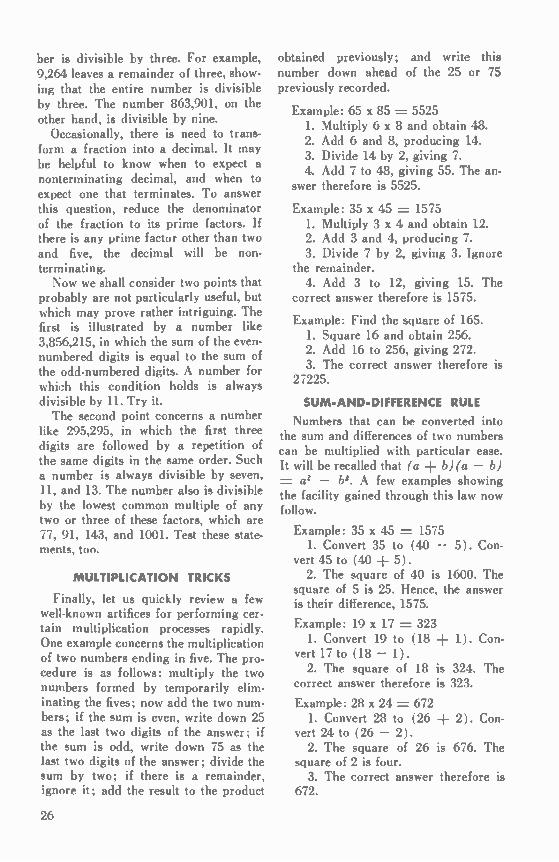
Finally, let us quickly review a few well-known artifices for performing cer-tain multiplication processes rapidly. One example concerns the multiplication of two numbers ending in five. The pro-cedure is as follows: multiply the two numbers formed by temporarily elim-inating the fives; now add the two num-bers; if the sum is even, write down 25 as the last two digits of the answer; if the sum is odd, write down 75 as the last two digits of the answer; divide the sum by two; if there is a remainder, ignore it; add the result to the product
obtained previously; and write this number down ahead of the 25 or 75 previously recorded.
Example: 65 x 85 = 5525 1. Multiply 6 x 8 and obtain 48. 2. Add 6 and 8, producing 14. 3. Divide 14 by 2, giving 7. 4. Add 7 to 48, giving 55. The an-
swer therefore is 5525.
Example: 35 x 45 = 1575 1. Multiply 3 x 4 and obtain 12. 2. Add 3 and 4, producing 7. 3. Divide 7 by 2, giving 3. Ignore
the remainder. 4. Add 3 to 12, giving 15. The
correct answer therefore is 1575.
Example: Find the square of 165. 1. Square 16 and obtain 256. 2. Add 16 to 256, giving 272. 3. The correct answer therefore is
27225.
SUM-AND-DIFFERENCE RULE
Numbers that can be converted into the sum and differences of two numbers can be multiplied with particular ease. It will be recalled that (a ± b)(a - b) = a2 - b2. A few examples showing the facility gained through this law now follow.
Example: 35 x 45 = 1575 1. Convert 35 to (40 - 5). Con-
vert 45 to (40 ± 5). 2. The square of 40 is 1600. The
square of 5 is 25. Hence, the answer is their difference, 1575.
Example: 19 x 17 = 323 1. Convert 19 to (18 ± 1). Con-
vert 17 to (18 - 1). 2. The square of 18 is 324. The
correct answer therefore is 323.
Example: 28 x 24 = 672 1. Convert 28 to (26 ± 2). Con-
vert 24 to (26 - 2). 2. The square of 26 is 676. The
square of 2 is four. 3. The correct answer therefore is
672.
26

SQUARE-OF-A-BINOMIAL RULE
The algebraic law governing the square of a binomial, (a :4= b)2 = a2 2ab b2, is often useful in corn-
puling the squares of various numbers. Suppose, for example, it were not re-membered that 324 is the square of 18. The correct answer is easily obtained by performing the steps below.
1. Convert 18 to (20 — 2). 2. Square 20, arriving at 400. 3. Multiply 2 x 2 x 20, arriving
at 80. 4. Square 2, arriving at 4. 5. The answer therefore is 400 —
30 ± 4, or 324. Example: Find the square of 34. 1. The square of 30 is 900. 2. Multiply 30 x 4 x 2, arriving at
240. 3. The square of 4 is 16. 4. The answer is 900 + 240 ± 16,
or 1156. In addition to the preceding artifices,
there are various tricks which are sug-gested by common sense, according to the circumstance. Suppose a multiplica-tion of 24 by 13 is required. Express 13 as 10 ± 3, multiply 24 by 3 to ob-tain 72, and add to 240. The answer is 312. Of course, this is exactly what is done in the conventional multiplication operation, but if visualization of rows of figures is difficult, it may be helpful to resort to the suggested procedure.
APPENDIX
It shall first be proved that the re-mainder of any number divided by nine is equal to the remainder obtained by dividing the sum of the digits of the number by nine. Any number in the conventional sys-
tem can be expressed in the following m7nner: N .= ao 10a1 102a2 103a3
10"a„ where N = the number, ao = the digit in the unit column,
al = the digit in the tenths column, and so on.
Let S = ao + a1 + az . . . an
Then N — S = (10 — 1) al ± (100 — 1) az ± (1000 — 1) az . . . ± (10" — 1) an
Evidently, all the coefficients on the right-hand side are a series of nines; that is, N — S = 9a1 99a2 999a3
Since the right-hand member is di-visible by nine, (N — S)/9 is equal to an integer. This can be expressed as
( N — 51 /9 = 1 where I is the integer. Therefore,
N/9 = I + S 9. This relation shows that the same re-
mainder obtains when a number is divided by nine and when the sum of its digits is divided by nine. The propo-sition has therefore been proved. Multiply both sides of the preceding
equation by nine, resulting in N =-- 91 S. It follows that if S is divisible by
three, nine, the number N is divisible by three, nine. To find the remainder of a number
divided by nine, it is permissible to continue the process of summing the digits indefinitely. For if the number .37„597 yields the same remainder when divided by nine as does the sum of its digits, 31, it follows that the sum of three and one when divided by nine will leave the same remainder as 31. Thus, the remainder is four. Now let us ap-proach the same question by recogniz-ing that division is the process of find-ing how many units of the divisor are contained in the dividend. Therefore, when the digits are added, we may ex-clude all units of nine. For example, in summing 3, 7, 5, 9, 7, we exclude (cast out) the nine immediately, leaving 22, which contains two units of nine (18) plus the remainder four. This procedure
27

gives us a second method of summing digits as a means of finding the re-mainder of a number divided by nine. Let us devise a check for addition.
Consider the number NI, N2, N3, . which can be expressed:
N1 = 9,1 ± r1
• •T
N2 = 9q2 rz N3 = 9q3 r3
and so on, where the q's represent the number of times nine is contained in a number and the r's represent the re-mainders. Therefore, N1+ N2 + NS • • • = 9 (Q1 + Q2 ±
q3 . . .) ri rz r3 It follows that if the individual re-
mainders are added and the nines of this sum are cast out, the resulting number should be equal to the re-mainder obtained by casting out nines of the answer to the addition.
Now let us devise a check for multi-plication. Since N1 = 9,1 + r1 and N2 = 9 q2 rz, their product is 81nin2 9 q1r2 9,2r1 ± r1r2. Thus, the re-mainder of the product is equal to the remainder obtained by dividing rirz by nine; in other words, by casting out the nines of the product of the two re-mainders.
The rule for divisibility by two, lour, eight, . . . is proved by examining a number expressed in terms of ten. N = a0 10a1 102a2
10"a„ where the a's have the meaning described previously. Since the second, third, fourth, etc., columns from the right represent increasing powers of 10, as shown in the preceding equation, each such column is clearly divisible by two, regardless of the digit. For the entire number to be divisible by two, there-fore, it is necessary only that the digit in the unit column, ao, be divisible by two. I 1 the number is to be divisible by four, the number composed of the digits in the units and tens columns must be divisible by lour, since four will divide into 103, 103, etc. Similarly, a number
is divisible by eight if the number com-posed of the digits in the units, tens, and hundreds columns is divisible by eight, since eight will divide into 103, 104, etc. The same reasoning holds for divisibility by 16. The criterion for nonterminating deci-
mals is easily deduced. Any decimal represents a fraction for which the de-nominator is 10", where n equals the number of places in the decimal. If the original fraction is first reduced to low-est terms, and then the denominator is resolved into prime factors, it follows that the number 10n, which is actually the denominator of the decimal, can be a multiple of the original denominator only if five and two are the sole prime numbers of that denominator. Now it shall be proved that if the sum
of the digits in the even places is equal to the sum of the digits in the odd places, the number is divisible by 11. Let N = a0 10ai 102a2 ± • • •
10"an ± • • • D = a0 — al ± az — a3 . . . N — D = ai (10 + 1) + az (102 — 1) ± a3 (103 ± 1) . . .
The last term on the right is an (10" ± 1) or an (10" — 1) as n is odd or even. Hence, every term on the right is divis-ible by (10 -I- 1), or 11. If the sums of the digits in the odd and even places are equal, D = 0, and the proposition is proved. Suppose the number N observes the
sequence al, az, a3, al, az, a3. Then N = a3 10a2 102a1 102a3 ▪ 104a2 105a1
Immediately, it is evident that D = a3 — az -I- al — a3 ± az — al = 0, showing that the number is divisible by 11. Subtract D from N. N — D = az(10 ± 1) -I- 111(102 — 1) ± a3(103 ± 1) ± a2(104 — 1) + a1(105 -I- 1) = ai(100,100) ± az (10,010) ▪ a3(1001)
= (7) (11) (13) (100a1 10a2 + az)
28

Since D = 0, N is divisible by 7 and 13 as well as by 11. The rule for multiplying numbers
ending in five will first be proved for two-digit numbers. Write such numbers as (10ai -I- 5) and (10a2 -I- 5). For example, 65 is equivalent to (6 x 10 ± 5).
(10ai ± 5) (10a2 ± 5) = 100a1a2+ 50(a1 a2) ± 25 = 100a1a2 --1-'100(a1 a2) (5/10) ± 25
= 100a1a2 100(ai a2) /2 -I- 25
A study of the foregoing relationship wili show that the rule for multiplying numbers ending in five has been proved. This will be made clear by considering the example 35 x 45. Here al = 3 and a2 .= 4. The first term of the answer,
100a1a2, is equal to 1200. The second term, 100(ai a2)/2, is equal to 700/2 = 350. The last term is 25. Con-sequently, their sum is 1,575.
To extend the rule for larger numbers ending in five, such as 135, 5,675, and so on, let al = bici . . . and let a2 = b2c2 . . ., where the letters desig-nate the respective digits of the number. Since a1a2 now represents (bici . . .) (b2c2 . . .), and (a1 a2) represents the sum of bici . . . and b2c2 ., the original proof is still valid.
REFERENCES
Hall, H. S., and Knight, S. R., Higher Algebra, MacMillan and Company, Limited. 1948. Wentworth, G. A., College Algebra, Ginn & Company, 1888.
Last Month's "What's Your Answer?" The Great Joule Robbery
The disappearance of 200 joules is explained by the fact that the little demon carried them off in his box. A reconstruction of the crime requires an application of the following funda-mentals: 1. The voltage across the coils must at all instants equal the applied voltage.
2. Inductance is effectively the "mass" of a current, and as such opposes only a change in an elec-tron flow.
3. Inductance in henries equals the induced voltage per change in amperes per second. Or, rearrang-ing, the change in amperes per second equals the induced voltage per henry.
4. Energy is absorbed by a circuit element when the electrons enter at the negative terminal and leave at the positive terminal, and energy is lost if the electrons flow in the reverse direction relative to the voltage across the circuit ele-ment.
5. One watt equals one joule per sec-ond, or the number of joules equals the average power in watts times the time in seconds.
When S, is closed, the voltage across L1 is (12 volts — 4 volts) = 8 volts. This voltage can only occur if the cur-rent is rising at a rate I/second = 8 volts/8 henries = 1 ampere per second. Ten seconds later, when S2 is closed,
the current through L, will have risen to 10 amperes. Closing S2 shorts out the 12-volt battery, and the fuse action re-moves it completely from the circuit. The two coils are now connected in
parallel, so the total inductance is now 8 henries/2 = 4 henries, and the ap-plied voltage is now 4 volts, but in the opposite direction. This means that the current must now change in the op-
posite direction at a rate I/second = 4 volts/4 henries = 1 ampere per second. In the absence of frictional forces (re-
sistance) or an up-hill potential gradient (the 4-volt battery), the inductance L, would maintain the 10-ampere current, just as the inertia of a moving ball would maintain the ball's velocity after an initial force were removed. Nor would L, share the current with Lo, since both would oppose any change in the electron flow. The change that actually occurs, then, is due entirely to the presence of the 4-volt battery. The reverse voltage across L, can
only occur if the current falls at a rate I/second = 4 volts/8 henries = 1/2 ampere per second. Similarly, 4 volts across L2 can only
occur if the current rises (in a direction opposite to the flow through L1) at a rate of 1/2 ampere per second. The fall of current in L, and the rise
of current in L2 provide an effective de-crease for the circuit as a whole of 1 ampere per second. At the end of 10 seconds, the current
through the battery circuit will have fallen to zero, the current through L, will have fallen to 5 amperes, and the current through L2 will have risen to 5 amperes. At this point, the little demon disconnects the box from the external circuit, and thus runs away with a cir-culating current of 5 amperes.
With an average current of 5 amperes for 10 seconds, the 12-volt battery do-nated J = VI.,et =_ 12 x 5 x 10 -= 600 joules. With an average current of 5 amperes
for 20 seconds, the 4-volt battery re-ceived J = 4 x 5 x 20 = 400 joules.
The stolen energy in the magnetic field is the difference or J = 1/2 LI2 1/2 (L, L2)I2 = 16/2 x 52 -= 200 j oules.
30

Material needed lor
"What's Your Answer?"
One of the most difficult problems faced by the BULLETIN staff is that of obtaining suitable problems for the "What's Your Answer?" feature. It is an inter-esting fact that this feature, by far the most popular item in each issue, has produced a greater number of written comments than any other portion of the magazine, but, strangely enough, fewer submitted manuscripts. Certainly, among the nearly 8000 BULLETIN read-
ers, there must be a great number who know of suit-able problems as yet unpublished. Therefore, any reader who wishes to do so may consider this as a hint. To be acceptable for publication, your problem
must pertain to some phase of electronics, it must be briefly stated, and it must have a valid solution (sup-plied with the original manuscript). Do you have one that fits these requirements?
In Coming Issues Did you ever wonder why two manufacturers of a particular
antenna type often publish radiation patterns which appear widely different in shape and in relative size of corresponding lobes, and yet obviously apply to the same basic design? If you did, a new article by Gail W. Woodward, titled "Antenna Pattern Plots," will explain the situation for you in next month's issue. Also to appear in the February issue, is Installment IV of
John Buchanan's very popular "Introduction to Transistor Electronics," as well as a very practical writeup on "Switch-board Ringing Interference Elimination," by Philco Field Engineer F. C. Farrar.
31
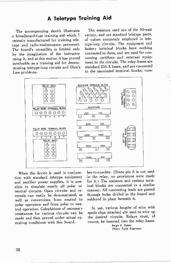
A Teletype Training Aid
The accompanying sketch illustrates a breadboard-type training aid which I recently manufactured for training tele-type and radio-maintenance personnel. The board's versatility is limited only by the imagination of the instructor using it, and at this station it has proved invaluable as a training aid for demon-strating teletype-loop circuits and Ohm's Law problems.
RELAY BASE
e
2 O 0 6 3 O 0
4 0 0
RELAY BASE TERMINAL BLOCK
eoeeeee 2 5 • 5 6 7
RELAY BASE TERMINAL BLOCK
oeee0e0 I 2 3 • 5 6 7
RELAY BASE
The resistors used are of the 10-watt variety, and are standard teletype parts, of values commonly employed in tele-type-loop circuits. The equipment and battery terminal blocks have nothing connected to them, and are used for con-necting rectifiers and external equip-ment to the circuits. The relay bases are standard 255-A bases, and are connected to the associated terminal blocks num-
RESISTOR TERMINAL BLOCK
Ak'e72®.3e94®1:e 16 e rf &le ei9 020 e
e e RESISTORS
1725 1725
W
Ial 2000 600
0000
N 12)
2000 1000
•000
W
I 2000 600
12-4-1 121
When the device is used in conjunc-tion with standard teletype equipment and rectifier power supplies, it is pos-sible to simulate nearly all polar or neutral circuits. Open circuits and re-versals can easily be demonstrated, as well as conversions from neutral to polar operation and from polar to neu-tral operation. Calculations of necessary resistances for various circuits can be made and then proved under actual op-erating conditions with this board.
2,
% .2 Oi wir
ber-to-number. (Since pin 8 is not used in the relay, no provisions were made for it.) The resistors and resistor term-inal blocks are connected in a similar manner. All connecting leads are passed through holes drilled in the board and soldered in place beneath it.
In use, various lengths of wire with spade clips attached are used to wire up the desired circuits. Relays must, of course, be inserted into the relay bases.
Regis E. Gatos Philco Field Engineer
32


le ,PHILCO
tril TE 6IREP V 1 wORLD WIDE V
SERVICE i/
Ori/
AN-287 Printed in U.S.A.