Embed Size (px)
Citation preview
Vision-based Absolute Localization for Unmanned Aerial Vehicles
Aurélien Yol, Bertrand Delabarre, Amaury Dame, Jean-Émile Dartois and Eric Marchand
Abstract— This paper presents a method for localizing anUnmanned Aerial Vehicle (UAV) using georeferenced aerialimages. Easily maneuverable and more and more affordable,UAVs have become a real center of interest. In the last fewyears, their utilization has significantly increased. Today, theyare used for multiple tasks such as navigation, transportationor vigilance. Nevertheless, the success of these tasks could notbe possible without a highly accurate localization which can,unfortunately be often laborious. Here we provide a multipleusage localization algorithm based on vision only. However,a major drawback with vision-based algorithms is the lackof robustness. Most of the approaches are sensitive to scenevariations (like season or environment changes) due to the factthat they use the Sum of Squared Differences (SSD). To preventthat, we choose to use the Mutual Information (MI) which isvery robust toward local and global scene variations. However,dense approaches are often related to drift disadvantages. Here,we solve this problem by using georeferenced images. Thelocalization algorithm has been implemented and experimen-tal results are presented demonstrating the localization of ahexarotor UAV fitted with a downward looking camera duringreal flight tests.
I. INTRODUCTION
Initially introduced by the US Army during World War I(1917), UAVs were, for a long time, considered both veryunreliable and inaccurate in term of maneuverability and nav-igation capabilities. Mostly used for military tasks claimedto be too risky or dangerous for humans, they were referredas the "Eyes of the Army" [19]. Today, they have reachedsuch a level of sophistication that their usage and appli-cation have become a real technological challenge. Wideand expanding, UAVs applications are commonly associatedwith exploration, inspection or surveillance tasks. A decidingfactor for the success of these tasks is the localization ornavigation capability of the drone. Unfortunately, this can beparticularly difficult when dealing with low-quality InertialMeasurement Unit (IMU), Global Positioning System (GPS),or when flying in bad weather conditions (which decreasesthe quality of the GPS navigation). Even though someapproaches for robust Inertial/GPS localization have beenstudied [18], lack of precision and signal interferences stillhave to be considered. An alternative to avoid these problemsis to mount a vision system on the UAV which can providea temporary alternative to IMU/GPS navigation unit.
Images are offering a wealth of information, and videocameras, if they are not already present, are cheap andlight enough to be mounted on board. While vision-based
A. Yol is with Inria Rennes, Lagadic team, Rennes, France.B. Delabarre and E. Marchand are with Université de Rennes 1, IRISA,
INRIA Lagadic team, Rennes, France. [email protected]. Dame is with University of Oxford, Oxford, United-Kingdom.J.-E. Dartois is with Inria Rennes, DiverSE team, Rennes France.
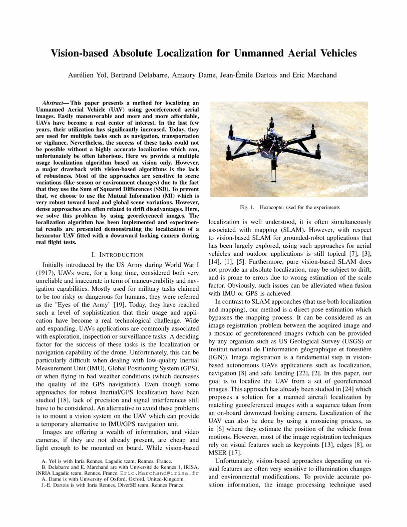
Fig. 1. Hexacopter used for the experiments
localization is well understood, it is often simultaneouslyassociated with mapping (SLAM). However, with respectto vision-based SLAM for grounded-robot applications thathas been largely explored, using such approaches for aerialvehicles and outdoor applications is still topical [7], [3],[14], [1], [5]. Furthermore, pure vision-based SLAM doesnot provide an absolute localization, may be subject to drift,and is prone to errors due to wrong estimation of the scalefactor. Obviously, such issues can be alleviated when fusionwith IMU or GPS is achieved.
In contrast to SLAM approaches (that use both localizationand mapping), our method is a direct pose estimation whichbypasses the mapping process. It can be considered as animage registration problem between the acquired image anda mosaic of georeferenced images (which can be providedby any organism such as US Geological Survey (USGS) orInstitut national de l’information géographique et forestière(IGN)). Image registration is a fundamental step in vision-based autonomous UAVs applications such as localization,navigation [8] and safe landing [22], [2]. In this paper, ourgoal is to localize the UAV from a set of georeferencedimages. This approach has already been studied in [24] whichproposes a solution for a manned aircraft localization bymatching georeferenced images with a sequence taken froman on-board downward looking camera. Localization of theUAV can also be done by using a mosaicing process, asin [6] where they estimate the position of the vehicle frommotions. However, most of the image registration techniquesrely on visual features such as keypoints [13], edges [8], orMSER [17].
Unfortunately, vision-based approaches depending on vi-sual features are often very sensitive to illumination changesand environmental modifications. To provide accurate po-sition information, the image processing technique used
remains crucial. Here, we use a dense or direct method. Alsocalled template based registration, it has barely been exploredwhen dealing with UAV localization [16]. The objectiveof this method is to optimize, for the camera motion, asimilarity function between the image acquired by the cameraand a reference template (here one of the georeferencedimages). The choice of the similarity function is fundamentalespecially considering outdoor scenes. First, as in [16], isthe Sum of Squared Differences (SSD) [4], which comparesthe luminance of each pixels. Unfortunately, this method isvery sensitive to scene variations such as season, weatheror environment changes. More advanced techniques use theSum of Conditional Variance (SCV) [21] or the NormalizedCross Correlation (NCC) [23]. They are more robust thanthe SSD but still sensitive to local intensity variations. Inthis paper, we use the Mutual Information (MI) [25], [9].Contrary to the previous optimization functions, MI, evenif more complex to compute, is robust to local and globalchanges since it is based on the amount of information sharedby the current and reference (georeferenced) images.
The paper is organized as follows. First, we introduce theabsolute localization problem applied for UAVs navigation.Then the main principles of differential template tracking arerecalled and the warping functions used for the localizationare introduced. Finally, the experimental results show the ro-bustness of our approach in difficult environment conditionsboth on specific images and real flight sequences (for whicha comparison with GPS logs is available).
II. ABSOLUTE LOCALIZATION: OVERVIEW
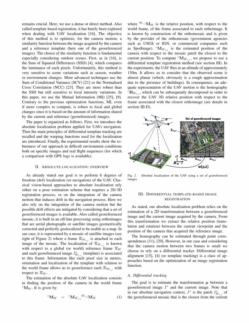
As already stated our goal is to perform 6 degrees offreedom (dof) localization (or navigation) of the UAV. Clas-sical vision-based approaches to absolute localization relyeither on a pose estimation scheme that requires a 2D-3Dregistration process, or on the integration of the cameramotion that induces drift in the navigation process. Here wealso rely on the integration of the camera motion but thepossible drift effects are mitigated by considering that a set ofgeoreferenced images is available. Also called georeferencedmosaic, it is built in an off-line processing using orthoimagesthat are aerial photographs or satellite images geometricallycorrected and perfectly geolocalized to be usable as a map. Inour case, it is represented by a mosaic of satellite images (seeright of Figure 2) where a frame RWi,j
is attached to eachimage of the mosaic. The localization of RWi,j
is knownwith respect to a global (or world) reference frame RW
and each georeferenced image I∗Wi,j(template) is associated
to this frame. Information like each pixel size in meters,orientation and localization of the template with relation tothe world frame allows us to georeference each RWi,j
withrespect to RW .
The estimation of the absolute UAV localization consistsin finding the position of the camera in the world framecMW . It is given by:
cMW = cMWi,j
Wi,jMW (1)
where Wi,jMW is the relative position, with respect to theworld frame, of the frame associated to each orthoimage. Itis known by construction of the orthomosaic and is givenby the provider of the orthomosaic (government agenciessuch as USGS or IGN, or commercial companies suchas SpotImage). cMWi,j is the estimated position of thecamera with respect to the mosaic patch the closest to thecurrent position. To compute cMWi,j
, we propose to use adifferential template registration method (see section III). Inthe experiments, the UAV flies at an altitude of approximately150m. It allows us to consider that the observed scene isalmost planar (which, obviously is a rough approximationdue to the presence of buildings). In consequence, an ade-quate representation of the UAV motion is the homographycHWi,j
, which can be subsequently decomposed in order torecover the UAV 3D relative position with respect to theframe associated with the closest orthoimage (see details insection III-D).
Set of georeferenced images
Rw1,0 Rw3,0Rw2,0Y
XRw
ww2,2wI
It
w(μ,t)X
YZ
μ̂t
Fig. 2. Absolute localization of the UAV using a set of georeferencedimages.
III. DIFFERENTIAL TEMPLATE-BASED IMAGEREGISTRATION
As stated, our absolute localization problem relies on theestimation of a 2D transformation between a georeferencedimage and the current image acquired by the camera. Fromthis transformation we extract the relative position (trans-lation and rotation) between the current viewpoint and theposition of the camera that acquired the reference image.
The homography can be estimated through point corre-spondences [11], [20]. However, in our case and consideringthat the camera motion between two frames is small wechoose to rely on a differential tracker. Differential imagealignment [15], [4] (or template tracking) is a class of ap-proaches based on the optimization of an image registrationfunction.
A. Differential tracking
The goal is to estimate the transformation µ between ageoreferenced image I∗ and the current image. Note thatin our absolute navigation context, I∗ is the patch I∗Wi,j
ofthe georeferenced mosaic that is the closest from the current
estimated UAV position. In the case of a similarity functionf , the problem can be written1 as :
µ̂t = arg maxµ
f(I∗, w(It,µ)) (2)
where we search the transformation µ̂t that maximizes thesimilarity between the template I∗ and the warped currentimage It. In the case of a dissimilarity function the problemwould be simply inverted in the sense that we would searchthe minimum of the function f .
To solve the maximization problem, the assumption madein the differential image registration approaches is that thedisplacement of the object between two consecutive framesis quite small. The previous estimated transformation µ̂t−1can therefore be used as the first estimation of the currentone to perform the optimization of f and incrementally reachthe optimum µ̂t.
B. Similarity measure
One essential choice remains the one of the alignmentfunction f . One natural solution is to choose the function fas the sum of squared differences of the pixel intensitiesbetween the reference image and the transformed currentimage [4]:
µ̂t = arg minµ
∑x∈I∗
(I∗(x)− It(w(x,µ)))2 (3)
where the summation is computed on each point x of thereference image. As suggested by its definition, this dissimi-larity function is very sensitive to illumination variations. Inour case, variation between the current and reference imagesmay go far beyond a simple illumination variation. Whenacquired at different dates or seasons, reference and currentimages may be very different and the SSD may prove to bean inefficient dissimilarity function.
NCC and ZNCC have shown some very good results inalignment problems [12] but in this paper we propose todefine our alignment function as the mutual information [25],[9]. Originating from the information theory, MI is a measureof statistical dependency between two signals (or two imagesin our case) that is robust to large variations of appearance.In that case, the problem can be formulated as:
µ̂ = arg maxµ
MI (I∗(x), I(w(x,µ))) . (4)
Rather than comparing intensities, as considered by the SSD,MI is the quantity of information shared between two randomvariables. The mutual information of two images I and I∗
is then given by the following equation:
MI(I, I∗) = h(I) + h(I∗)− h(I, I∗) (5)
where the entropy h(I) is a measure of variability of arandom variable, here the image I and h(I, I∗) is the jointentropy of two random variables which can be defined as thevariability of the couple of variables (I, I∗).
1For the purpose of clarity, the warping function w is here used in anabuse of notation to define the overall transformation of the image I by theparameters µ. Its proper formulation should be preferred using w(x,µ) todenote the position of the point x transformed using the parameter µ.
This can be simply computed by image histogram manipu-lation. If r are the possible values of I and pI(r) = P (I = r)is the probability distribution function of r, then the Shannonentropy h(I) of I is given by:
h(I) = −∑r
pI(r) log (pI(r)) . (6)
The probability distribution function of the gray-level valuesis then simply given by the normalized histogram of theimage I . The entropy can therefore be considered as adispersion measure of the image histogram. Following thesame principle, the joint entropy h(I, I∗) of two randomvariables I and I∗ can be computed as:
h(I, I∗) = −∑r,t
pII∗(r, t) log (pII∗(r, t)) (7)
where r and t are respectively the possible values of thevariables I and I∗, and pII∗(r, t) = P (I = r∩I∗ = t) is thejoint probability distribution function. In our problem I andI∗ are images. Then r and t are the gray-level values of thetwo images and the joint probability distribution function is anormalized bi-dimensional histogram of the two images. Asfor the entropy, the joint entropy corresponds to a dispersionmeasure of the joint histogram of (I, I∗).
If this expression is combined with the previously defineddifferential motion estimation problem, we can consider thatthe image I is depending on the displacement parametersµ. If we use the same warp function notation as in sectionIII-A, MI can thus be written with respect to µ:
MI(w(I,µ), I∗) = h(w(I,µ)) + h(I∗)− h(w(I,µ), I∗).(8)
C. Optimization of the similarity measure
Multiple solutions exist to compute the update of the cur-rent displacement parameters and perform the optimization.Baker and Matthews showed that two formulations wereequivalent [4] depending on whether the update is actingon the current image or the reference. The former is thedirect compositional formulation which considers that theupdate is applied to the current image. A second equivalentformulation, that is considered in our problem, is the inversecompositional formulation which considers that the updatemodifies the reference image, so that, at each iteration k,∆µ is chosen to maximize:
∆µk = arg max∆µ
f(w(I∗,∆µ), w(It,µk)). (9)
In this case the current parameters is updated using:
w( w−1(x,∆µk),µk)→ w(x,µk+1). (10)
Considering the mutual information as the similarity func-tion, we have:
∆µk = arg max∆µ
MI(I∗(w(x,∆µ)), I(w(x,µk))
). (11)
In the inverse compositional formulation [4], since theupdate parameters are applied to the reference image, the
derivatives with respect to the displacement parameters arecomputed using the gradient of the reference image. Thus,these derivatives can be partially precomputed and the algo-rithm is far more efficient.
Estimating the update using a first-order optimizationmethod such as a steepest gradient descent is not adapted.Such non-linear optimizations are usually performed using aNewton’s method that assumes the shape of the function tobe parabolic. Newton’s method uses a second order Taylorexpansion at the current position µk−1 to estimate the update∆µ required to reach the optimum of the function (wherethe gradient of the function is null). The same estimationand update are performed until the parameter µk effectivelyreaches the optimum. The update is estimated following theequation:
∆µ = −H−1MIG>MI (12)
where GMI and HMI are respectively the gradient andHessian matrices of the mutual information with respectto the update ∆µ. Following the inverse compositionalformulation defined in equation (9) those matrices are equalto:
GMI =∂MI(w(I∗,∆µ), w(I,µ))
∂∆µ(13)
HMI =∂2MI(w(I∗,∆µ), w(I,µ))
∂∆µ2. (14)
The details of the calculation of equations (13) and (14)can be found in [10] and an optimized version that allows asecond order optimization of the mutual information as beenrecently proposed in [9].
D. Warp functions
Along with the choice of the similarity function, the choiceof an adequate warping function is fundamental consideringthat the UAV underwent an arbitrary 3D motion. It has tobe noted that there does not exist a 2D motion model thataccounts for any kind of 3D camera motion.
With respect to the camera altitude, ground altitude vari-ations are often small. In that case, the homography, that isable to account for any 3D motion when the scene is planar,is a good candidate for the transformation.
A point xt, expressed in homogeneous coordinates xt =(xt, yt, 1), is transfered in the other image using the follow-ing relation:
w(xt,µ) = Hxt (15)
where H is the homography. This homography can be linkedto the 3D camera motion (t,R) by:
H = (R +t
dnT ) (16)
where n and d are the normal and the distance to thereference plane (here the ground) expressed in the cameraframe. Knowing the homography H it is possible to decom-pose it in order to retrieve the absolute displacement of thecamera [11].
Alternatively, if the camera is a real nadir camera (ie, theimage plane and “flat” ground are almost parallel), the ho-mography appears to be over parameterized. The sRt modelaccounts for 3D motions when the image and scene planesremain parallel (ie, optical axis perpendicular to the ground).It is a combination of a 2D rotation R2d (which accounts forthe rotation around the optical axis), a translation t2d and ascale factor s. The warp of a point xt = (xt, yt)
T is thengiven by:
w(xt,µ) = sR2dxt + t2d. (17)
As for the homography, from this simplified form, we canalso retrieve the absolute 3D displacement of the camera.In the experiments the camera is mounted on the UAVwith a IMU piloted camera which allows the camera to bein a Nadir configuration where pitch and roll motions arecounterbalanced. We therefore rely on this sRt model.
IV. EXPERIMENTAL RESULTS
The proposed method has been validated using flight-testdata acquired with a GoPro camera mounted on an hexarotorUAV (Figure 1). The UAV size is approximately 70cm. It ispowered by six 880kv motors. It also has an embedded GPSwhich is only used as “ground-truth” to assess the computedlocalization. Our localization process is currently done offboard via an Intel Xeon 2.8GHz.
The flight data were collected above the Université deRennes 1 campus. The resolution of the georeferenced mo-saic used for image registration is approximately 0.2 meterper pixel. All the experiments used a motorized Nadir systemwhere pitch and roll motions of the UAV are counterbalancedvia a brushless gimbal. Flights altitude is approximately 150meters high (±25m). Perspective effects are limited andscene is assumed to be planar. These particularities makethe usage of the sRt warping function more suitable thanthe homography which is overparametrized. As a result, 4degrees of freedom localization are estimated and definedby the geometric coordinates of the UAV, its altitude andheading.
A. Analysis of the similarity measure
In order to assess the choice of MI as our similarityfunction, a simple experiment was realized that compare theSSD and MI in extreme conditions.
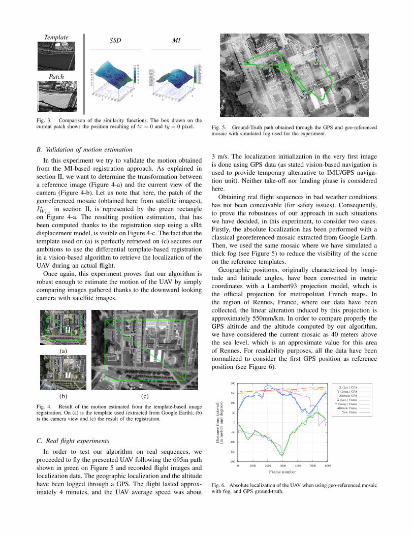
We consider a reference template of 650×500 pixelsextracted from Google Earth in the region of Edmonton, CAin summer and a current image of the same scene in winter.A translation of ±20 pixels along each axis is consideredand the values of the SSD and MI are computed between thereference and current patch. The shapes of the cost functions(equation(3) and (4)), along with the considered images, areshown on Figure 3. The result is consistent with our choice.MI shows a well defined maximum at the expected positionproving that it is perfectly suited for localization, contraryto the SSD which is tricked by the differences resultingof seasonal changes, lighting conditions or environmentalmodifications.
Template
Patch
SSD MI
-20 -15 -10 -5 0 5 10 15 20-20-15
-10-5
0 5
10 15
20
75 76 77 78 79 80 81
ty
tx
75 76 77 78 79 80 81
-20 -15 -10 -5 0 5 10 15 20-20-15
-10-5
0 5
10 15
20
0.065 0.07
0.075 0.08
0.085 0.09
0.095 0.1
0.105 0.11
0.115 0.12
ty
tx
0.065 0.07 0.075 0.08 0.085 0.09 0.095 0.1 0.105 0.11 0.115 0.12
Fig. 3. Comparison of the similarity functions. The box drawn on thecurrent patch shows the position resulting of tx = 0 and ty = 0 pixel.
B. Validation of motion estimation
In this experiment we try to validate the motion obtainedfrom the MI-based registration approach. As explained insection II, we want to determine the transformation betweena reference image (Figure 4-a) and the current view of thecamera (Figure 4-b). Let us note that here, the patch of thegeoreferenced mosaic (obtained here from satellite images),I∗Wi,j
in section II, is represented by the green rectangleon Figure 4-a. The resulting position estimation, that hasbeen computed thanks to the registration step using a sRtdisplacement model, is visible on Figure 4-c. The fact that thetemplate used on (a) is perfectly retrieved on (c) secures ourambitions to use the differential template-based registrationin a vision-based algorithm to retrieve the localization of theUAV during an actual flight.
Once again, this experiment proves that our algorithm isrobust enough to estimate the motion of the UAV by simplycomparing images gathered thanks to the downward lookingcamera with satellite images.
(a)
(b) (c)Fig. 4. Result of the motion estimated from the template-based imageregistration. On (a) is the template used (extracted from Google Earth), (b)is the camera view and (c) the result of the registration.
C. Real flight experiments
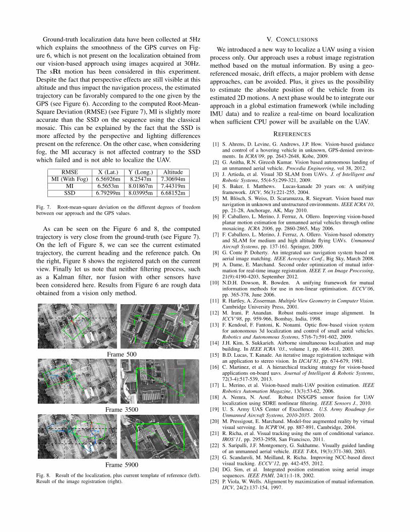
In order to test our algorithm on real sequences, weproceeded to fly the presented UAV following the 695m pathshown in green on Figure 5 and recorded flight images andlocalization data. The geographic localization and the altitudehave been logged through a GPS. The flight lasted approx-imately 4 minutes, and the UAV average speed was about
Fig. 5. Ground-Truth path obtained through the GPS and geo-referencedmosaic with simulated fog used for the experiment.
3 m/s. The localization initialization in the very first imageis done using GPS data (as stated vision-based navigation isused to provide temporary alternative to IMU/GPS naviga-tion unit). Neither take-off nor landing phase is consideredhere.
Obtaining real flight sequences in bad weather conditionshas not been conceivable (for safety issues). Consequently,to prove the robustness of our approach in such situationswe have decided, in this experiment, to consider two cases.Firstly, the absolute localization has been performed with aclassical georeferenced mosaic extracted from Google Earth.Then, we used the same mosaic where we have simulated athick fog (see Figure 5) to reduce the visibility of the sceneon the reference templates.
Geographic positions, originally characterized by longi-tude and latitude angles, have been converted in metriccoordinates with a Lambert93 projection model, which isthe official projection for metropolitan French maps. Inthe region of Rennes, France, where our data have beencollected, the linear alteration induced by this projection isapproximately 550mm/km. In order to compare properly theGPS altitude and the altitude computed by our algorithm,we have considered the current mosaic as 40 meters abovethe sea level, which is an approximate value for this areaof Rennes. For readability purposes, all the data have beennormalized to consider the first GPS position as referenceposition (see Figure 6).
-200
-150
-100
-50
0
50
100
150
200
0 1000 2000 3000 4000 5000 6000
Dis
tance
fro
m t
ake-
off
(in m
eter
s and d
egre
es)
Frame number
X (Lat.) GPS
Y (Long.) GPS
Altitude GPS
X (Lat.) Vision
Y (Long.) Vision
Altitude Vision
Yaw Vision
Fig. 6. Absolute localization of the UAV when using geo-referenced mosaicwith fog, and GPS ground-truth.
Ground-truth localization data have been collected at 5Hzwhich explains the smoothness of the GPS curves on Fig-ure 6, which is not present on the localization obtained fromour vision-based approach using images acquired at 30Hz.The sRt motion has been considered in this experiment.Despite the fact that perspective effects are still visible at thisaltitude and thus impact the navigation process, the estimatedtrajectory can be favorably compared to the one given by theGPS (see Figure 6). According to the computed Root-Mean-Square Deviation (RMSE) (see Figure 7), MI is slightly moreaccurate than the SSD on the sequence using the classicalmosaic. This can be explained by the fact that the SSD ismore affected by the perspective and lighting differencespresent on the reference. On the other case, when consideringfog, the MI accuracy is not affected contrary to the SSDwhich failed and is not able to localize the UAV.
RMSE X (Lat.) Y (Long.) AltitudeMI (With Fog) 6.56926m 8.2547m 7.30694m
MI 6.5653m 8.01867m 7.44319mSSD 6.79299m 8.03995m 6.68152m
Fig. 7. Root-mean-square deviation on the different degrees of freedombetween our approach and the GPS values.
As can be seen on the Figure 6 and 8, the computedtrajectory is very close from the ground-truth (see Figure 7).On the left of Figure 8, we can see the current estimatedtrajectory, the current heading and the reference patch. Onthe right, Figure 8 shows the registered patch on the currentview. Finally let us note that neither filtering process, suchas a Kalman filter, nor fusion with other sensors havebeen considered here. Results from Figure 6 are rough dataobtained from a vision only method.
Frame 500
Frame 3500
Frame 5900Fig. 8. Result of the localization, plus current template of reference (left).Result of the image registration (right).
V. CONCLUSIONS
We introduced a new way to localize a UAV using a visionprocess only. Our approach uses a robust image registrationmethod based on the mutual information. By using a geo-referenced mosaic, drift effects, a major problem with denseapproaches, can be avoided. Plus, it gives us the possibilityto estimate the absolute position of the vehicle from itsestimated 2D motions. A next phase would be to integrate ourapproach in a global estimation framework (while includingIMU data) and to realize a real-time on board localizationwhen sufficient CPU power will be available on the UAV.
REFERENCES
[1] S. Ahrens, D. Levine, G. Andrews, J.P. How. Vision-based guidanceand control of a hovering vehicle in unknown, GPS-denied environ-ments. In ICRA’09, pp. 2643-2648, Kobe, 2009.
[2] G. Anitha, R.N. Gireesh Kumar. Vision based autonomous landing ofan unmanned aerial vehicle. Procedia Engineering, vol 38, 2012.
[3] J. Artieda, et al. Visual 3D SLAM from UAVs. J. of Intelligent andRobotic Systems, 55(4-5):299-321, 2009.
[4] S. Baker, I. Matthews. Lucas-kanade 20 years on: A unifyingframework. IJCV, 56(3):221-255, 2004.
[5] M. Blösch, S. Weiss, D. Scaramuzza, R. Siegwart. Vision based mavnavigation in unknown and unstructured environments. IEEE ICRA’10,pp. 21-28, Anchorage, AK, May 2010.
[6] F. Caballero, L. Merino, J. Ferruz, A. Ollero. Improving vision-basedplanar motion estimation for unmanned aerial vehicles through onlinemosaicing. ICRA 2006, pp. 2860-2865, May 2006.
[7] F. Caballero, L. Merino, J. Ferruz, A. Ollero. Vision-based odometryand SLAM for medium and high altitude flying UAVs. UnmannedAircraft Systems, pp. 137-161. Springer, 2009.
[8] G. Conte P. Doherty. An integrated uav navigation system based onaerial image matching. IEEE Aerospace Conf., Big Sky, March 2008.
[9] A. Dame, E. Marchand. Second order optimization of mutual infor-mation for real-time image registration. IEEE T. on Image Processing,21(9):4190-4203, September 2012.
[10] N.D.H. Dowson, R. Bowden. A unifying framework for mutualinformation methods for use in non-linear optimisation. ECCV’06,pp. 365-378, June 2006.
[11] R. Hartley, A. Zisserman. Multiple View Geometry in Computer Vision.Cambridge University Press, 2001.
[12] M. Irani, P. Anandan. Robust multi-sensor image alignment. InICCV’98, pp. 959-966, Bombay, India, 1998.
[13] F. Kendoul, F. Fantoni, K. Nonami. Optic flow-based vision systemfor autonomous 3d localization and control of small aerial vehicles.Robotics and Autonomous Systems, 57(6-7):591-602, 2009.
[14] J.H. Kim, S. Sukkarieh. Airborne simultaneous localisation and mapbuilding. In IEEE ICRA ’03., volume 1, pp. 406-411, 2003.
[15] B.D. Lucas, T. Kanade. An iterative image registration technique withan application to stereo vision. In IJCAI’81, pp. 674-679, 1981.
[16] C. Martinez, et al. A hierarchical tracking strategy for vision-basedapplications on-board uavs. Journal of Intelligent & Robotic Systems,72(3-4):517-539, 2013.
[17] L. Merino, et al. Vision-based multi-UAV position estimation. IEEERobotics Automation Magazine, 13(3):53-62, 2006.
[18] A. Nemra, N. Aouf. Robust INS/GPS sensor fusion for UAVlocalization using SDRE nonlinear filtering. IEEE Sensors J., 2010.
[19] U. S. Army UAS Center of Excellence. U.S. Army Roadmap forUnmanned Aircraft Systems, 2010-2035. 2010.
[20] M. Pressigout, E. Marchand. Model-free augmented reality by virtualvisual servoing. In ICPR’04, pp. 887-891, Cambridge, 2004.
[21] R. Richa, et al. Visual tracking using the sum of conditional variance.IROS’11, pp. 2953-2958, San Francisco, 2011.
[22] S. Saripalli, J.F. Montgomery, G. Sukhatme. Visually guided landingof an unmanned aerial vehicle. IEEE T-RA, 19(3):371-380, 2003.
[23] G. Scandaroli, M. Meilland, R. Richa. Improving NCC-based directvisual tracking. ECCV’12, pp. 442-455, 2012.
[24] DG. Sim, et al. Integrated position estimation using aerial imagesequences. IEEE PAMI, 24(1):1-18, 2002.
[25] P. Viola, W. Wells. Alignment by maximization of mutual information.IJCV, 24(2):137-154, 1997.


![FY18 RWDC State Unmanned Aerial System Challenge ... · Unmanned Aerial System Challenge: Practical Solutions to ... , Real World Design Challenge ... , unmanned aerial vehicle [UAV])](https://img.pdfslide.us/doc/110x75/5ae85cfb7f8b9a8b2b8fe5e5/fy18-rwdc-state-unmanned-aerial-system-challenge-aerial-system-challenge-practical.jpg)