Embed Size (px)
Citation preview
7/31/2019 Visakh Seminar
http://slidepdf.com/reader/full/visakh-seminar 1/20
AN ACTUATOR FAILURE TOLERANT CONTROL
SCHEME FOR AN UNDERWATER REMOTELY
OPERATED VEHICLE
SEMINAR REPORT
submitted in partial fulfillment of
the requirements for the award of M.Tech Degree in
Electronics and Communication Engineering (Applied Electronics and
Instrumentation)
of the University of Kerala
Submitted by
VISAKH .V
First Semester
M.Tech, Applied Electronics and Instrumentation
DEPARTMENT OF ELECTRONICS AND COMMUNICATION ENGINEERING
COLLEGE OF ENGINEERING
TRIVANDRUM
2012
7/31/2019 Visakh Seminar
http://slidepdf.com/reader/full/visakh-seminar 2/20
DEPARTMENT OF ELECTRONICS AND COMMUNICATION ENGINEERING
COLLEGE OF ENGINEERING
TRIVANDRUM
CERTIFICATE
This is to certify that this seminar report entitled “An Actuator Failure Tolerant Con-
trol Scheme for an Underwater Remotely Operated Vehicle ” is a bonafide record
of the work done by Visakh V, under my guidance towards partial fulfillment of the re-
quirements for the award of Master of Technology Degree in Electronics and Com-munication Engineering (Applied Electronics and Instrumentation), of the Univer-
sity of Kerala during the year 2012.
Mr. Biji Jacob
Associate Professor
Dept. of ECE
College of Engineering, Trivandrum(Seminar Coordinator)
Mr. Vinod B R
Assistant Professor
Dept. of ECE
College of Engineering, Trivandrum(Guide)
Prof. David J
Head of Department
Dept. of ECE
College of Engineering, Trivandrum
7/31/2019 Visakh Seminar
http://slidepdf.com/reader/full/visakh-seminar 3/20
ACKNOWLEDGEMENTS
I would like to express my sincere gratitude and heartful indebtedness to my guide
Mr. Vinod B R, Assistant Professor, Department of Electronics and Communication
Engineering for his valuable guidance and encouragement in pursuing this seminar.
I am thankful to Prof. David J, Head of the Department, Department of Electronics
and Communication Engineering for their help and support.
I also extend my hearty gratitude to Mr. Biji Jacob, Seminar Co-ordinator, Depart-
ment of ECE, College of Engineering Trivandrum for providing necessary facilities and
their sincere co-operation. My sincere thanks are extended to all the teachers of the
department of ECE and to all my friends for their help and support.
Above all I am thankful to the God Almighty.
Visakh .V
ii
7/31/2019 Visakh Seminar
http://slidepdf.com/reader/full/visakh-seminar 4/20
ABSTRACT
This paper proposes an actuator fault-tolerant control scheme, composed of the
usual modules performing detection, isolation, accommodation, designed for a class of
nonlinear systems, and then applied to an underwater remotely operated vehicle (ROV)
used for inspection purposes. Detection is in charge of a residual generation module,
while a sliding-mode-based approach has been used both for ROV control and fault
isolation, after the application of an input decoupling nonlinear state transformation
to the ROV model. Finally, control reconfiguration is performed exploiting the inher-
ent redundancy of actuators. An extensive simulation study has been also performed,
supporting the effectiveness of the proposed approach.
iii
7/31/2019 Visakh Seminar
http://slidepdf.com/reader/full/visakh-seminar 5/20

7/31/2019 Visakh Seminar
http://slidepdf.com/reader/full/visakh-seminar 6/20
LIST OF FIGURES
2.1 ROV operational configuration. . . . . . . . . . . . . . . . . . . . . 2
2.2 ROV propellers system. . . . . . . . . . . . . . . . . . . . . . . . . 3
4.1 Incidence Matrix. . . . . . . . . . . . . . . . . . . . . . . . . . . . 9
ii
7/31/2019 Visakh Seminar
http://slidepdf.com/reader/full/visakh-seminar 7/20
CHAPTER 1
INTRODUCTION
THE applied research area known as marine robotics is receiving increasing at-
tention both by research institutes and by companies interested in the exploitation of
sea resources. In particular, the development of underwater unmanned vehicles (UV) is
attracting noticeable interest as a cost-effective solution for performing complex tasks
in the underwater environment (e.g., environmental data gathering, transportation of
assembling modules for submarine installations, inspection of underwater structures).
Since the UV is expected to operate in a largely uncertain underwater environment, the
control problem of such vehicles is particularly challenging, also in view of the inher-
ent nonlinearity of the dynamics, the presence of external unmeasurable disturbances,
the high uncertainty level in the model. In such a context, fault tolerance is crucial, to
overcome the possible occurrence of faults in the vehicle actuators , and allow nonethe-
less the vehicle to satisfactorily track the assigned reference, thus fulfilling its mission
objectives.
The actuator failure tolerant control scheme presented in this paper is com-
posed by the usual modules performing detection, isolation, accommodation of faults
by control reconfiguration. Detection is performed by a residual generation module,
developed according to structural analysis issues using the nonlinear model of the ROV.
The fault identification module is based on sliding mode control (SMC). In particu-
lar, an input decoupling nonlinear state transformationhas been applied to the nonlinear
model of the ROV, and three sliding surfaces have been designed for the decoupled non-
linear plant in order to ensure that each sliding surface is affected by a single thruster
only (the redundant actuator can assume arbitrary values within a given range). Such
sliding surfaces have been used both for designing a robust ROV control algorithm en-
suring plant regulation, and for performing fault isolation. Since a decoupled sliding
mode control law is used, any fault occurrence can be associated to a single thruster,
and the faulty actuator is this way isolated. Finally, once the failed actuator has been
identified, control reconfiguration is performed using the redundant healthy actuator.
In other words, the control activity is redistributed among the actuators still working
such that the failed actuator is compensated for, and control performances are this way
preserved.
7/31/2019 Visakh Seminar
http://slidepdf.com/reader/full/visakh-seminar 8/20
CHAPTER 2
MATHEMATICAL MODEL OF THE ROV
2.1 ROV Nonlinear Model
The equations describing the ROV dynamics have been obtained from classical me-
chanics. The ROV considered as a rigid body can be fully described with six degrees
of freedom, corresponding to the position and orientation with respect to a given coor-
dinate system.
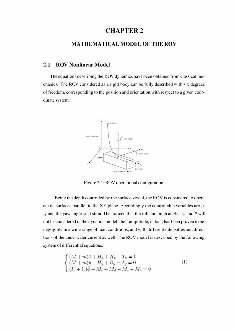
Figure 2.1: ROV operational configuration.
Being the depth controlled by the surface vessel, the ROV is considered to oper-
ate on surfaces parallel to the XY plane. Accordingly the controllable variables are ,x
,y and the yaw angle φ. It should be noticed that the roll and pitch angles ψ and θ will
not be considered in the dynamic model, their amplitude, in fact, has been proven to be
negligible in a wide range of load conditions, and with different intensities and direc-
tions of the underwater current as well. The ROV model is described by the following
system of differential equations:
7/31/2019 Visakh Seminar
http://slidepdf.com/reader/full/visakh-seminar 9/20
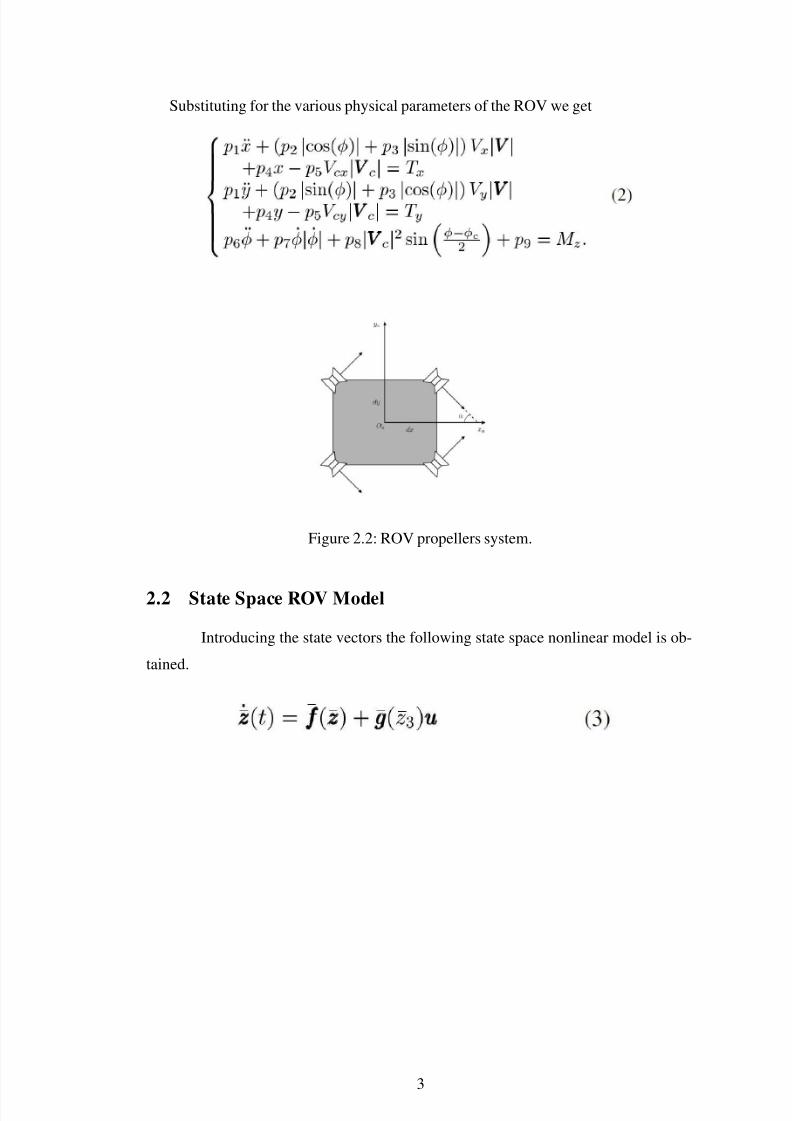
Substituting for the various physical parameters of the ROV we get
Figure 2.2: ROV propellers system.
2.2 State Space ROV Model
Introducing the state vectors the following state space nonlinear model is ob-
tained.
3
7/31/2019 Visakh Seminar
http://slidepdf.com/reader/full/visakh-seminar 10/20
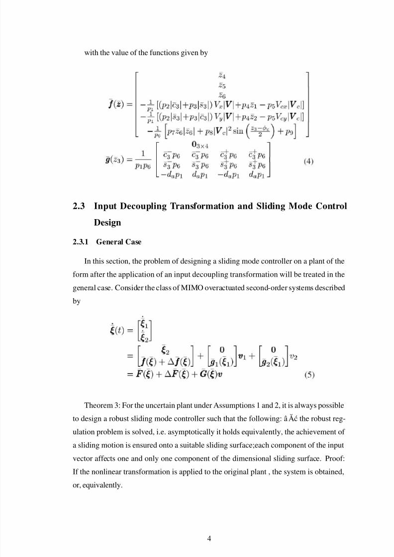
with the value of the functions given by
2.3 Input Decoupling Transformation and Sliding Mode Control
Design
2.3.1 General Case
In this section, the problem of designing a sliding mode controller on a plant of the
form after the application of an input decoupling transformation will be treated in the
general case. Consider the class of MIMO overactuated second-order systems described
by
Theorem 3: For the uncertain plant under Assumptions 1 and 2, it is always possible
to design a robust sliding mode controller such that the following: âAc the robust reg-
ulation problem is solved, i.e. asymptotically it holds equivalently, the achievement of
a sliding motion is ensured onto a suitable sliding surface;each component of the input
vector affects one and only one component of the dimensional sliding surface. Proof:
If the nonlinear transformation is applied to the original plant , the system is obtained,
or, equivalently.
4
7/31/2019 Visakh Seminar
http://slidepdf.com/reader/full/visakh-seminar 11/20
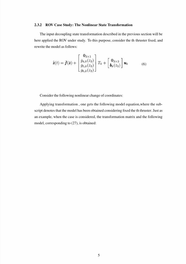
2.3.2 ROV Case Study: The Nonlinear State Transformation
The input decoupling state transformation described in the previous section will be
here applied the ROV under study. To this purpose, consider the th thruster fixed, and
rewrite the model as follows:
Consider the following nonlinear change of coordinates:
Applying transformation , one gets the following model equation,where the sub-
script denotes that the model has been obtained considering fixed the th thruster. Just as
an example, when the case is considered, the transformation matrix and the following
model, corresponding to (27), is obtained:
5
7/31/2019 Visakh Seminar
http://slidepdf.com/reader/full/visakh-seminar 12/20
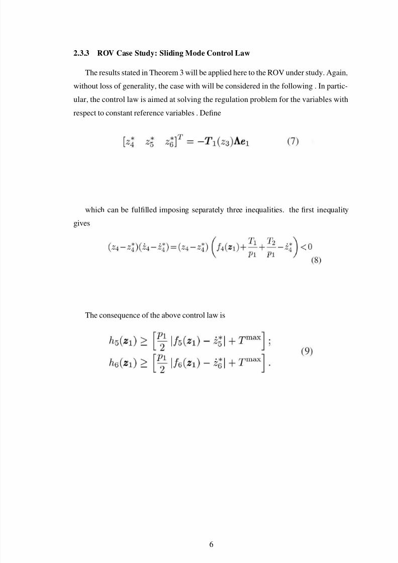
2.3.3 ROV Case Study: Sliding Mode Control Law
The results stated in Theorem 3 will be applied here to the ROV under study. Again,
without loss of generality, the case with will be considered in the following . In partic-
ular, the control law is aimed at solving the regulation problem for the variables with
respect to constant reference variables . Define
which can be fulfilled imposing separately three inequalities. the first inequality
gives
The consequence of the above control law is
6
7/31/2019 Visakh Seminar
http://slidepdf.com/reader/full/visakh-seminar 13/20
CHAPTER 3
FAULT TOLERANT CONTROL SCHEME
In this section, the proposed fault tolerant control scheme will be described. In the
scenario considered in this paper, each thruster is an actuator potentially affected by
faults. The basic idea is that, whenever a failure is detected and identified, a supervisor
performs a control reconfiguration exploiting thrusters redundancy (three propellers are
enough to control the ROV trajectory). Accordingly, the FDI scheme considered here
consists of: 1) a supervisor, in charge of performing the control reconfiguration among
the available set of redundant inputs, according to the output of the FDI device; 2)
a fault detection (FD) unit, based on residual analysis; 3) a fault isolation (FI) unit,
monitoring the three decoupled sliding surfaces, each of which is affected by a unique
thruster; 4) a robust sliding mode-based control law, designed on a decoupled model
of the ROV, able to guarantee the desired control performances accounting also for the
faulty thruster. The addressed potential faults belong to a wide class. First, the so-
called abrupt fault are considered. They are described by a step function, modeling
the case when the faulty variable is instantaneously stuck to an unknown but bounded
value. Such fault may occur when a failure of a component produce a sudden deviation
of the actuator dynamics as for example a valve completely failing to open or close,
a short circuit in the motor circuitry. This type of thruster faults has the following
model where the failure times are unknown. In other words where the failure times are
unknown. In other words, when a fault does occur on a thruster, this causes the complete
and permanent unavailability of the considered actuator at unknown time instant. This
means that, from the unknown time instant , it is not possible to recover the thruster
functionality and thus only the remaining working thrusters can be used to control the
vehicle. The case when a thruster undergoes a failure occurs.
Also, the behavior of a faulty device can be consequence of deterioration, obsoles-
cence or cumulation phenomena (cumulation of sediment, wear of impeller casing, silt
within pipelines, leaks in the machinery, erosion). These phenomena produce a small
instantaneous deviation of the actuator behavior, but it cumulates in time; as a result,
these faults can result in a loss of efficiency within the system.
7/31/2019 Visakh Seminar
http://slidepdf.com/reader/full/visakh-seminar 14/20
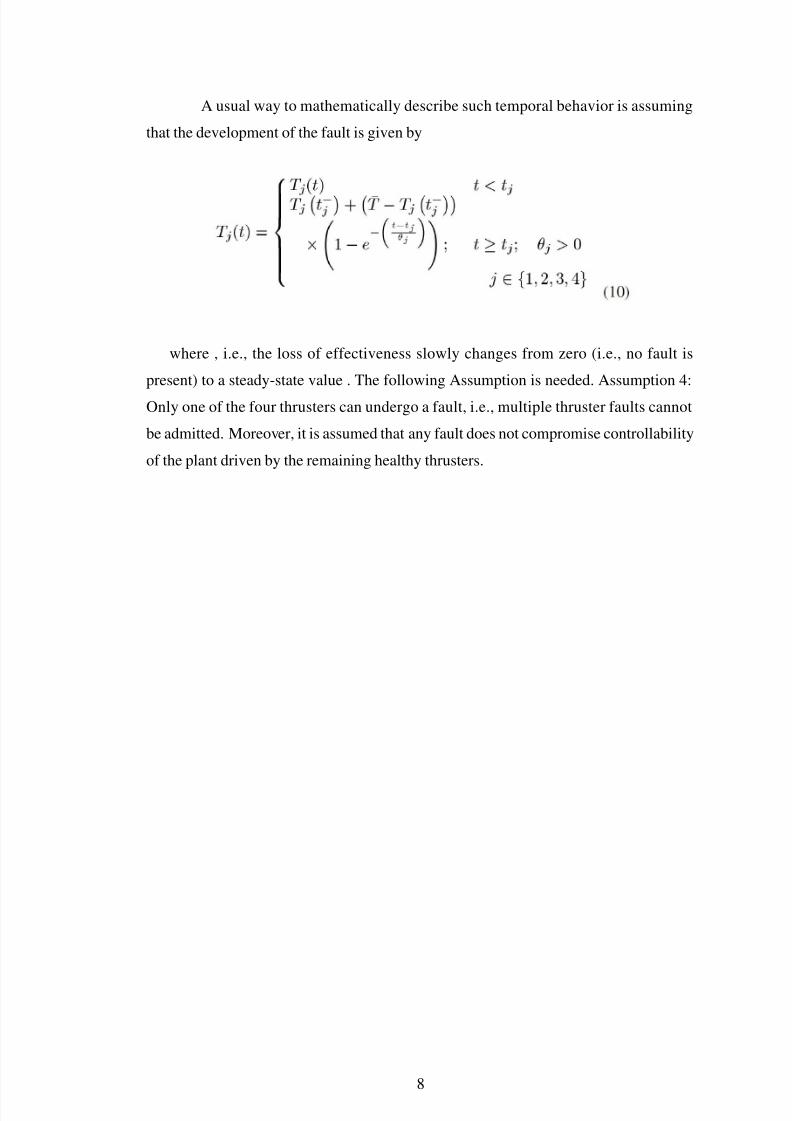
A usual way to mathematically describe such temporal behavior is assuming
that the development of the fault is given by
where , i.e., the loss of effectiveness slowly changes from zero (i.e., no fault is
present) to a steady-state value . The following Assumption is needed. Assumption 4:
Only one of the four thrusters can undergo a fault, i.e., multiple thruster faults cannot
be admitted. Moreover, it is assumed that any fault does not compromise controllability
of the plant driven by the remaining healthy thrusters.
8
7/31/2019 Visakh Seminar
http://slidepdf.com/reader/full/visakh-seminar 15/20
CHAPTER 4
FAULT DETECTION: THE RESIDUAL GENERATOR MODULE
The residual generator module is able to generate the residuals exploiting the main ideas
of the structural analysis . Structural analysis is a tool which investigates the structural
properties of dynamical system by analyzing its structural model . The basic tool for
the structural analysis is the concept of matching on matrix incidence or on a bipartite
graph.Amatching is a causal assignment which associates some system variables with
the system constraints from which they can be calculated. Variables contained in con-
straints that cannot be matched, cannot be calculated. Variables contained in constraints
that can be matched in several ways, can be calculated by different (redundant) means,
thus providing means for fault detection and a possibility for reconfiguration . Match-
ing on a structure graph of a dynamic system can disclose which subset of equations
provide a redundant description of the system. The matching process is essentially a
way to indicate which equations (or constraints) in a nonlinear system are needed to
find a solution for its variables. When there are more equations than needed, excess
equations can be used to check for validity of observations. If such an excess equation,
called unmatched constraint and known as residual, is not valid, this will indicate the
presence of a fault in the system.
The matching algorithm identifies the overdetermined parts of the system . The
result is a list of matched and unmatched constraints. The matched constraints result
while the unmatched constraints .
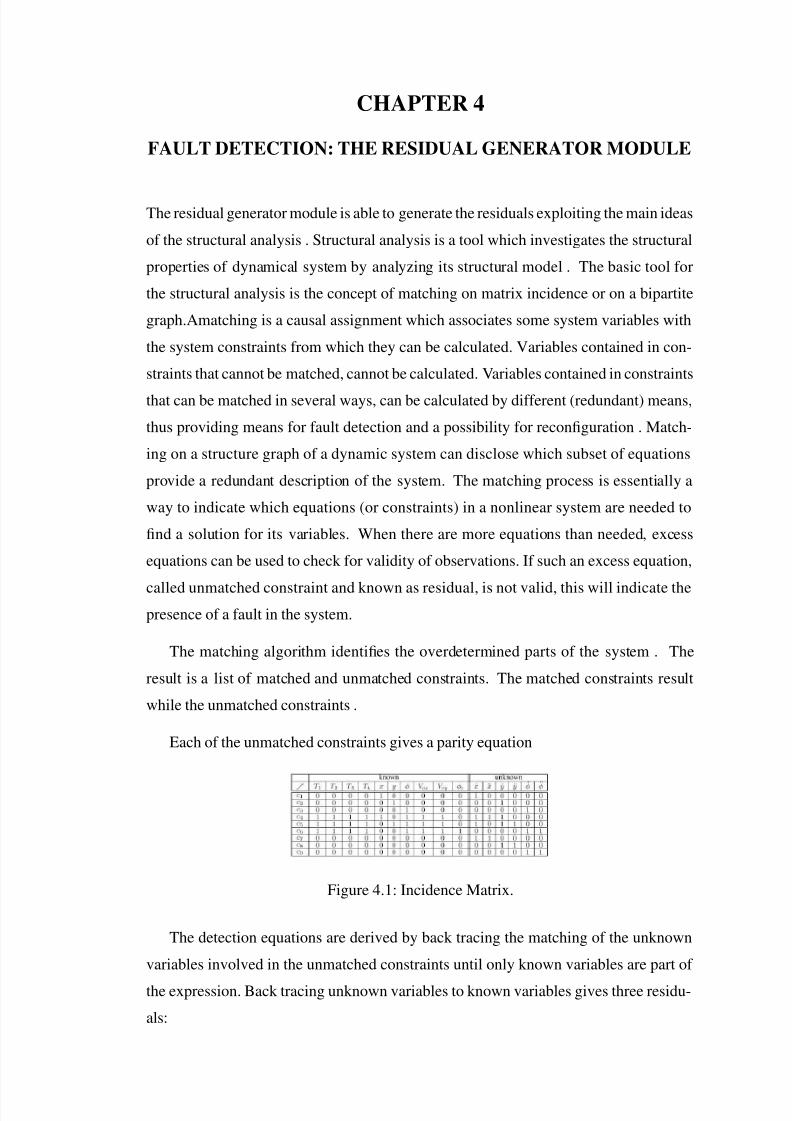
Each of the unmatched constraints gives a parity equation
Figure 4.1: Incidence Matrix.
The detection equations are derived by back tracing the matching of the unknown
variables involved in the unmatched constraints until only known variables are part of
the expression. Back tracing unknown variables to known variables gives three residu-
als:
7/31/2019 Visakh Seminar
http://slidepdf.com/reader/full/visakh-seminar 16/20
The role of the decision module is to determine whether the residuals differ signif-
icantly from zero and, from pattern of zero and nonzero residuals, to decide which are
the most likely fault/ failure effects, and in turn, which components could be the origin
of a fault or a failure. Residual evaluation consists to detect a change in the mean of
a normally distributed random sequence, which can be achieved by sequential change
detection algorithms like the cumulative sum (CUSUM) algorithm . This algorithm
is chosen to design the decision module of the failure detection system of the ROV.
Assumption 5: No faults occur during an initial transient phase immediately after the
startup of the ROV. This is not a limiting assumption, in view of the ROV types of
utilization and the missions the vehicle is expected to carry out.
10
7/31/2019 Visakh Seminar
http://slidepdf.com/reader/full/visakh-seminar 17/20
CHAPTER 5
FAULT ISOLATION
Once a failure is detected by FD module, the sliding-mode controller can be also ex-
ploited to perform fault isolation. Indeed, it can be simply performed using the follow-
ing check on the components of the sliding surface , since each component is affected
only by a single thruster
It follows that, whenever a fault has been detected by the FD module, the thruster
associated to the nonzero component of the sliding surface (if any) is to be considered
the failed actuator. In case no violation is detected by the FI module, then the occur-
rence a false alarm will be signaled to the supervisor.
Remark 6: The practical implementation of the previous rule requires of course the
use of a nonzero threshold , which could also coincide with the width of the boundary
layer needed, as well known, to avoid chattering .
Remark 7: About the eventual effect of sliding modes on fault signatures, it should
be noticed that if a fault detected by the residual generator does not affect any compo-
nent of the sliding surface, it simply means that the controller and the whole control
system is behaving correctly. It follows that signatures are not destroyed, but the fault
is isolated as soon as it becomes serious enough to disturb the effectiveness of the con-
troller.
7/31/2019 Visakh Seminar
http://slidepdf.com/reader/full/visakh-seminar 18/20
CHAPTER 6
CONTROL RECONFIGURATION
After a failure has been detected and isolated by the FD and FI module respectively, the
supervisor has to perform a control reconfiguration to preserve the desired performances
in face of the failure occurrence. In particular, the inherent redundancy of the considered
ROV can be exploited for fault accommodation. Consider the transformed decoupled
plant , derived setting to an arbitrary value, for an arbitrary integer . Assume that a fault
is detected, and that the failed thruster isolated by the FI module (i.e., associated to the
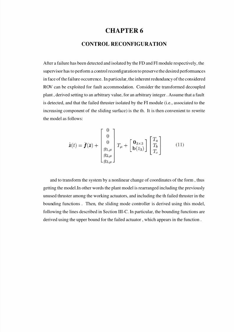
increasing component of the sliding surface) is the th. It is then convenient to rewrite
the model as follows:
and to transform the system by a nonlinear change of coordinates of the form , thus
getting the model.In other words the plant model is rearranged including the previously
unused thruster among the working actuators, and including the th failed thruster in the
bounding functions . Then, the sliding mode controller is derived using this model,
following the lines described in Section III-C. In particular, the bounding functions are
derived using the upper bound for the failed actuator , which appears in the function .
7/31/2019 Visakh Seminar
http://slidepdf.com/reader/full/visakh-seminar 19/20
CHAPTER 7
CONCLUSION
In view of the robustness properties of sliding-mode control, this procedure guarantees
the robust asymptotical vanishing of the tracking errors also in the presence of a faulty
actuator (with known upper bound), i.e., that robust regulation is achieved asymptoti-
cally. Eventhough one of the actuator fails due to some reason it will be detected by
the fault detection module and then the corresponding thruster will be isolated by the
fault isolation module.After that control reconfiguration is done and the ROV will now
operate using the three healthy actuators.
7/31/2019 Visakh Seminar
http://slidepdf.com/reader/full/visakh-seminar 20/20
REFERENCES
[1] Maria Letizia Corradini, Andrea Monteriu, and Giuseppe Orlando, “An Actua-
tor Failure Tolerant Control Scheme for an Underwater Remotely Operated Ve-
hicle,” IEEE Trans. Control Syst.Tech, vol. 19, no. 5, pp. 1036-1046, Sep. 2011.
[2] M.Blanke, H.Niemann, nd T.Lorentzen, “Structural Analysis- A case study of
romer satellite.”Proc,IFAC Safeprocess,Washington,DC,2003.
[3] V.Coocquempot, R.Izadi-Zamanabadi, M.Staroswiecki, and M.Blanke, “Resid-ual generation for the ship benchmark using structural approach,”Proc.UKACC
Int.Conf.(Conf.Publ.455), pp. 1480-1485, 1998.
[4] V.Utkin, “Sliding Modes in Control Optimization,” Berlin,Germany, Springer Ver-
lag, 1992.