Embed Size (px)
Citation preview
26TH DAAAM INTERNATIONAL SYMPOSIUM ON INTELLIGENT MANUFACTURING AND AUTOMATION
VIRTUAL PROTOTYPING AND OPTIMIZATION OF HEAVY MACHINE TOOLS
Petr Janda, Roman Polak
Ing.Petr Janda, Bc. Roman Polak, University of West Bohemia, Department of Machine Design
Abstract
This paper deals with virtual prototyping and optimization of heavy machine tools. Main focus is on static and dynamic
stiffness of heavy lathe. Analysis of virtual models of heavy lathes is very specific because the great influence on machine
stiffness has workpiece and machine base. In most cases the weight of workpiece is greater than the weight of machine
tool. The influence of workpiece and machine base on static and dynamic stiffness of heavy lathe is analysed in this work.
CAx software Siemens NX 10.0 is used for numerical analysis and optimization of heavy lathe.
Keywords: Machine Tool Design; FEM; Virtual Prototyping; Heavy Machine Tool; Optimization
This Publication has to be referred as: Janda, P[etr] & Polak, R[oman] (2016). Virtual Prototyping and Optimization
of Heavy Machine Tools, Proceedings of the 26th DAAAM International Symposium, pp.0967-0973, B. Katalinic (Ed.),
Published by DAAAM International, ISBN 978-3-902734-07-5, ISSN 1726-9679, Vienna, Austria
DOI: 10.2507/26th.daaam.proceedings.136
- 0967 -
26TH DAAAM INTERNATIONAL SYMPOSIUM ON INTELLIGENT MANUFACTURING AND AUTOMATION
1. Introduction
Czech Republic has a long tradition in the production of heavy machine tools. University of West Bohemia in
Pilsen cooperates with Skoda Machine Tool which produces the largest machine in the world (maximum workpiece up
to 350 tons) (Table 1). More than 90% of the production is made for export. The most important export territories are
China, Finland, The Netherlands, India, Japan, Canada, South Korea, Germany, Austria, Russia and Ukraine. Production
program of Skoda Machine Tool is heavy boring and milling machines and heavy lathes. The use of modern design
methods is necessary to achieve high quality products.
1.1. Heavy lathe
My research activity is focused on the issue of heavy lathes. Main parts of heavy lathe are machine bed,
headstock, tailstock and carriage saddle with cross slide. All of these parts have influence on stiffness of lathe. The aim
of my work is to propose a design methodology of heavy lathes.
SR 1000 SR 2000 SR 3000 SR 4000 SR 5000 SR 6000
Diameter over carriage [mm] 1000
1000 1300 2000 3000 3600
1300 1600 2500 3300 4200
1500 2000 3000 3600 5200
Torque [Nm] 12 000
1-1000 1-700 1-400 1-400 1-400
1-700 1-400 1-250 1-250 1-200
1-250 1-200 1-200 1-120
1-120
Max. workpiece length [mm] Up to 6000 3000-20000 4000-20000 4000-20000 4000-20000 10000-20000
Max. workpiece weight [t] 16
25 25 25 56 56
56 56 100 100
100 160 160
160 250 250
350
Power of main drive [kW] 51
60 60 60 60 60
100 100 100 100 100
140 140 140 140
200 200 200
330
Table 1. Parameters of heavy lathe
2. Literature overview
Design of heavy lathes is very specific. The analytical computations are good described in literature [3] but most
of information about virtual prototyping of this machines are not public. All our knowledges are from cooperation with
manufacturer [1, 4, 5]. Some authors wrote about numerical analysis of similar machines [6, 7, 8, 9]. This information
will be useful in future work.
3. Numerical analysis of heavy lathe
First step of this work is basic numerical analysis of simple virtual model of heavy lathe. The virtual model
including basic part of lathe (machine bed, tailstock and headstock). Main goal of this analysis is give the answers to the
two questions:
a) a)How to model connection between foundation and machine bed?
b) b)Is the model of workpiece replaceable by load?
3.1. Finite element model
For analysis only full solid body models of machine bed, headstock and tailstock are used. Material of all parts
of lathe is iron casting G40 (Young's Modulus = 140 000 MPa, Poisson's Ratio = 0.25, Mass Density = 7150 kg/m3)
- 0968 -
26TH DAAAM INTERNATIONAL SYMPOSIUM ON INTELLIGENT MANUFACTURING AND AUTOMATION
3.2. Boundary conditions
Connection between foundation and machine bed
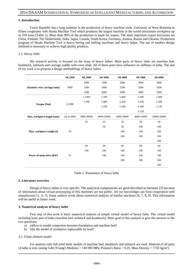
The connection between the foundation and the machine bed is realized using fixators. The BW-Fixator Series
RK for the levelling, adjustment and fixation is used (Fig. 1). Only information about axial stiffness is available in catalog.
Stiffness of this fixators (RK III) is 8000 kN/mm [2]. Radial stiffness of fixator is 25% of axial stiffness [1].
Fig. 1. BW-Fixator RK-III
This paper compares two methods of modeling of connection between the foundation and the machine bed:
Absolutely rigid connection.
Flexible connection (spring with stiffness)
Connection between headstock and machine bed
The connection between the headstock and the machine bed is realized using bolt connection. The numerical
analysis model using gluing connection.
Connection between tailstock and machine bed
The connection between the headstock and the machine bed is sliding connection with rack and pinion for linear
motion. During machining position is fixed. The numerical analysis model using gluing connection. In the future work
gluing will be replaced by contact connection.
Force load
Analysis includes force from the weight of the workpiece and the force of workpiece preload. The mass of
workpiece is 56 tons.
The force of the weight of the workpiece is divided into two halves. Force applied to headstock is FZ = - 274
680 N and force applied to tailstock is also FZ = - 274 680 N.
The force of workpiece preload is 75% of weight of workpiece. Force applied to headstock is FX = - 412 020 N
and force applied to tailstock is also FX = + 412 020 N.
Gravity is not included.
This paper compares two methods of applying of force loads to numerical model.
Analysis not including the geometry of workpiece.
Analysis including the geometry of workpiece.
- 0969 -
26TH DAAAM INTERNATIONAL SYMPOSIUM ON INTELLIGENT MANUFACTURING AND AUTOMATION
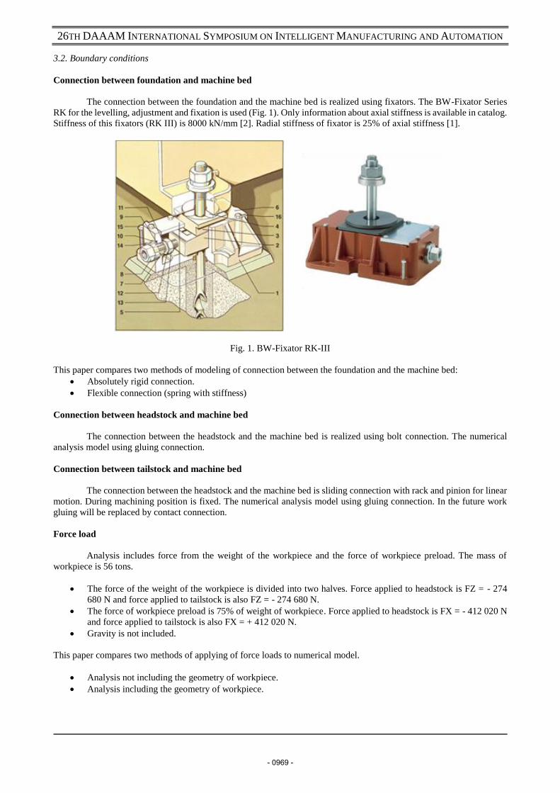
Fig. 2. Finite element model with boundary conditions
4. Results
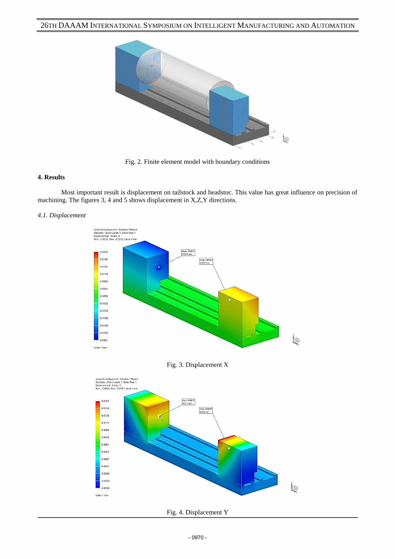
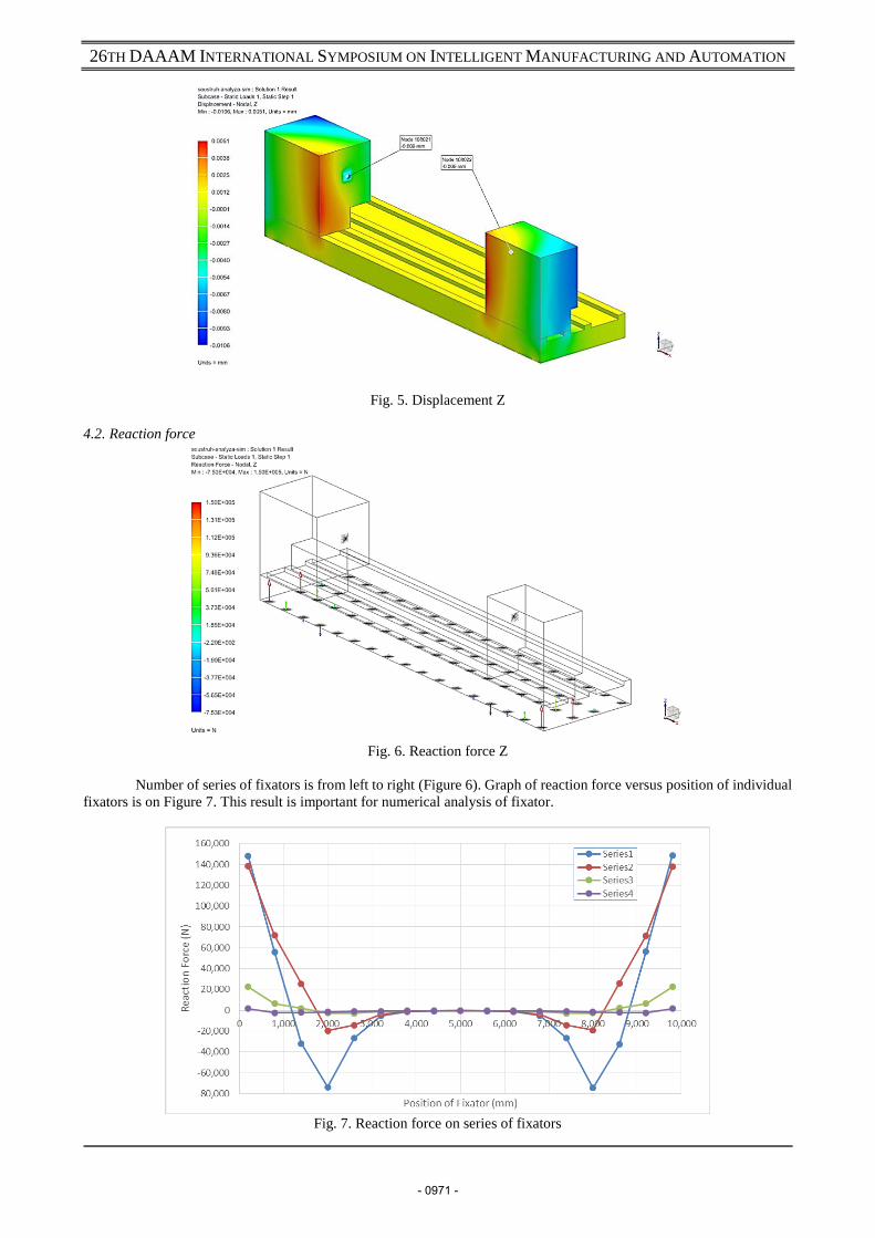
Most important result is displacement on tailstock and headstoc. This value has great influence on precision of
machining. The figures 3, 4 and 5 shows displacement in X,Z,Y directions.
4.1. Displacement
Fig. 3. Displacement X
Fig. 4. Displacement Y
- 0970 -
26TH DAAAM INTERNATIONAL SYMPOSIUM ON INTELLIGENT MANUFACTURING AND AUTOMATION
Fig. 5. Displacement Z
4.2. Reaction force
Fig. 6. Reaction force Z
Number of series of fixators is from left to right (Figure 6). Graph of reaction force versus position of individual
fixators is on Figure 7. This result is important for numerical analysis of fixator.
Fig. 7. Reaction force on series of fixators
- 0971 -
26TH DAAAM INTERNATIONAL SYMPOSIUM ON INTELLIGENT MANUFACTURING AND AUTOMATION
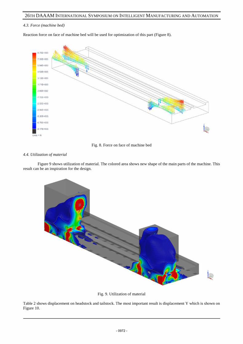
4.3. Force (machine bed)
Reaction force on face of machine bed will be used for optimization of this part (Figure 8).
Fig. 8. Force on face of machine bed
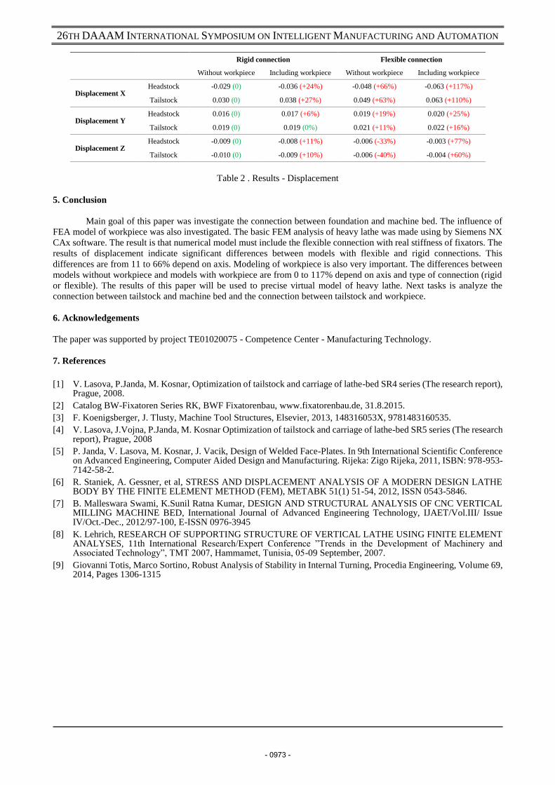
4.4. Utilization of material
Figure 9 shows utilization of material. The colored area shows new shape of the main parts of the machine. This
result can be an inspiration for the design.
Fig. 9. Utilization of material
Table 2 shows displacement on headstock and tailstock. The most important result is displacement Y which is shown on
Figure 10.
- 0972 -
26TH DAAAM INTERNATIONAL SYMPOSIUM ON INTELLIGENT MANUFACTURING AND AUTOMATION
Rigid connection Flexible connection
Without workpiece Including workpiece Without workpiece Including workpiece
Displacement X Headstock -0.029 (0) -0.036 (+24%) -0.048 (+66%) -0.063 (+117%)
Tailstock 0.030 (0) 0.038 (+27%) 0.049 (+63%) 0.063 (+110%)
Displacement Y Headstock 0.016 (0) 0.017 (+6%) 0.019 (+19%) 0.020 (+25%)
Tailstock 0.019 (0) 0.019 (0%) 0.021 (+11%) 0.022 (+16%)
Displacement Z Headstock -0.009 (0) -0.008 (+11%) -0.006 (-33%) -0.003 (+77%)
Tailstock -0.010 (0) -0.009 (+10%) -0.006 (-40%) -0.004 (+60%)
Table 2 . Results - Displacement
5. Conclusion
Main goal of this paper was investigate the connection between foundation and machine bed. The influence of
FEA model of workpiece was also investigated. The basic FEM analysis of heavy lathe was made using by Siemens NX
CAx software. The result is that numerical model must include the flexible connection with real stiffness of fixators. The
results of displacement indicate significant differences between models with flexible and rigid connections. This
differences are from 11 to 66% depend on axis. Modeling of workpiece is also very important. The differences between
models without workpiece and models with workpiece are from 0 to 117% depend on axis and type of connection (rigid
or flexible). The results of this paper will be used to precise virtual model of heavy lathe. Next tasks is analyze the
connection between tailstock and machine bed and the connection between tailstock and workpiece.
6. Acknowledgements
The paper was supported by project TE01020075 - Competence Center - Manufacturing Technology.
7. References
[1] V. Lasova, P.Janda, M. Kosnar, Optimization of tailstock and carriage of lathe-bed SR4 series (The research report), Prague, 2008.
[2] Catalog BW-Fixatoren Series RK, BWF Fixatorenbau, www.fixatorenbau.de, 31.8.2015.
[3] F. Koenigsberger, J. Tlusty, Machine Tool Structures, Elsevier, 2013, 148316053X, 9781483160535.
[4] V. Lasova, J.Vojna, P.Janda, M. Kosnar Optimization of tailstock and carriage of lathe-bed SR5 series (The research report), Prague, 2008
[5] P. Janda, V. Lasova, M. Kosnar, J. Vacik, Design of Welded Face-Plates. In 9th International Scientific Conference on Advanced Engineering, Computer Aided Design and Manufacturing. Rijeka: Zigo Rijeka, 2011, ISBN: 978-953-7142-58-2.
[6] R. Staniek, A. Gessner, et al, STRESS AND DISPLACEMENT ANALYSIS OF A MODERN DESIGN LATHE BODY BY THE FINITE ELEMENT METHOD (FEM), METABK 51(1) 51-54, 2012, ISSN 0543-5846.
[7] B. Malleswara Swami, K.Sunil Ratna Kumar, DESIGN AND STRUCTURAL ANALYSIS OF CNC VERTICAL MILLING MACHINE BED, International Journal of Advanced Engineering Technology, IJAET/Vol.III/ Issue IV/Oct.-Dec., 2012/97-100, E-ISSN 0976-3945
[8] K. Lehrich, RESEARCH OF SUPPORTING STRUCTURE OF VERTICAL LATHE USING FINITE ELEMENT ANALYSES, 11th International Research/Expert Conference ”Trends in the Development of Machinery and Associated Technology”, TMT 2007, Hammamet, Tunisia, 05-09 September, 2007.
[9] Giovanni Totis, Marco Sortino, Robust Analysis of Stability in Internal Turning, Procedia Engineering, Volume 69, 2014, Pages 1306-1315
- 0973 -