Embed Size (px)
Citation preview

Dr. Mahalingam College of Engineering and Technology, Pollachi.(An Autonomous Institution affiliated to Anna University , Chennai)
Continuous Comprehensive EvaluationTest-I – Key
11CE503 – STRUCTURAL ANALYSIS-I B.E. (CIVIL ENGINEERING)
Semester: V Date: 21.08.2012 Duration: 3 hours Maximum Marks: 75
Section – A Objective Questions (15x1=15 Marks)1. If there are ‘m’ members, ‘r’ unknown reaction components and ‘j’ number of joints in the pin-jointed plane
frame, then the degree of static indeterminacy is:A). m + r + 2j B). m - r + 2j, C). m + r - 2j, D). m + r - 3j [Ans: C]
2. A plane truss having ‘m’ members, ‘j’ joints and r external reactions, will be unstable if
A). (m + r)<2j B). m + r = 2j C). (m + r)>2j D). none of the above [Ans: C]
3. Number of unknown internal forces in each member of a rigid jointed plane frame is______. [Ans: 3]
4. Degree of static indeterminacy of a rigid-jointed plane frame having 15 members, 3 reaction components and 14 joints is______.
A). 2 B). 3 C). 6 D). 8 [Ans: C]
5. In a space truss which has ‘j’ number of joints and ‘r’ external reactions then, the degree of kinematic indeterminacy is
A). 2j-r B). 3j-r C). j-2r D). j-3r [Ans: B]
6. The number of independent joint displacements which are to be determined in the structure is called
A). Degree of static Indeterminacy B). Degree of kinematic indeterminacy C). External indeterminacy D). Internal indeterminacy [Ans: B]
7. Principle of superposition is applicable for non-linear systems. (True/False) [Ans: False]
8. A work done by a real force acting through a virtual displacement or a virtual force acting through a real displacement is called _______.[Ans: Virtual work].
9. The deflection at any point of a perfect frame can be obtained by applying a unit load at the joint in
A). vertical direction B). horizontal direction C). any inclined direction D). the direction in which the unit load is required. [Ans: D]
10. Virtual work Method is also referred as
A). Castigliano’s theorem B).Mohr’s theorem C).Unit load method D). Macaulay’s method [Ans: C]
11. Change in temperature in a determinate structure will not affect stresses in the members.(True/False) [Ans: True]
12. A single rolling load of 8 kN rolls along a girder of 15 m span. The absolute maximum bending moment will be _______ kN.m [Ans: 30kN.m]
13. The maximum bending moment due to a train of wheel loads on a simply supported girder
A). always occurs at center of span B). always occurs under the critical wheel load C). never occurs under a wheel load D). none of the above [Ans: B]
14. When an uniformly distributed load, shorter than the span of the girder, moves from left to right, then the conditions for maximum bending moment at a section is that

A). the head of the load reaches the section B). the tail of the load reaches the section C). the load position should be such that the section divides it equally on both sides D). the load position should be such that the section divides the load in the same ratio as it divides the span
[Ans:D]
15. When a series of wheel loads crosses a simply supported girder, the maximum bending moment under any given wheel load occurs when
A). the center of gravity of the load system is midway between the center of span and wheel load under consideration
B). the center of span is midway between the center of gravity of the load system and the wheel load under consideration
C). the wheel load under consideration is midway between the center of span and the center of gravity of the load system
D). none of the above [Ans: B]
Section – B Short Answer Questions (5x2=10 Marks)
16. Distinguish between plane truss and plane frame.
Ans: A plane truss is an articulated structure consisting members in a plane, pin jointed at their ends and carry axial forces only.
A plane frame is a structure consisting members in a plane, rigid jointed at their ends and carry bending moments, shear forces and axial forces.
17. What is material non-linearity?
Ans: Materials loaded beyond proportional limit, stress will not be proportional to strain even in the metallic materials because stress-strain relationship is not linear beyond that limit. When materials, such as soil, concrete, rubbery materials exhibiting non-linear stress-strain relationship or stressed beyond proportional limit, linear analysis will not yield accurate results. This kind of non linearity is due to the nature of material and hence it is called material non-linearity. Hence, non-linear analysis has to be employed to arrive accurate results.
18. Define statically indeterminate structure.
Ans: A structure is called statically indeterminate (or hyperstatic) structure when the static equilibrium equations are insufficient for determining the internal forces and reactions on that structure.
19. State principle of virtual work
Ans: The principle of virtual work can be stated ad follows:
If a deformable body in equilibrium is subjected to arbitrary virtual displacements associated with a compatibility condition, the virtual work done by the external forces on the body will be equal to virtual strain energy of the internal stresses.
20. What is an influence line? What are the uses of influence lines?
Ans: An influence line is a diagram represents, for any given frame or truss, the variation of structural response (such as bending moment, shear force, axial force, deformation) at one location in the structure for all positions of a moving unit load as it crosses the structure from one end to the other.Once the influence line diagram for a structural response is known for a location, the sum of the product of the load and the ordinate of ILD under load gives the structural response at that location. Thus computation of structural response is made easy for the moving loads.

4 m
30o 60oA B
C
100 kN
Fig. 1
Section – C Compulsory Descriptive Question (1x10=10 Marks)
21. Using virtual work method, determine the horizontal displacement of joint C of the steel truss for the loads shown in fig. 1. E=200kN/mm2 and sectional area of bar AB= 300mm2, AC= 400mm2 and BC= 600mm2. If the temperature is increased by 10ºC , 15ºC and 20ºC in members, AB, AC and BC respectively, calculate the additional horizontal displacement for change in temperature if linear thermal expansion coefficient α = 12x10 -
6 / °C. (10)
Length of Members (2 marks)
LAB = 4 mLAC = 3.464 mLBC = 2 m
Member forces for real load (2 marks)FAB = 43.302 kN FAC = -50 kN FBC = -86.603 kN
Member forces for unit horizontal load (2 marks)khAB = 0.25 kNkhAC = 0.866 kN khBC = -0.5 kN
Calculation - From the principle of virtual work, the virtual work equation for truss is (2marks)
1.∆=∑i=1
m k iF iLiA i Ei
+∑i=1
n
k i Liα i ΔT i
Where i denotes member number, k is the internal member forces due to virtual load, F i LiA iE i
is the real
displacement of ith member due to real load and Liαi ΔT i is the real displacement of ith member due to change in temperature.

Fig. 2
3m 3m 3m
2m
A B C D
FE
150 kN200 kN
MemberLi
(m)Ai
(m2)Ei
(kN/m2)k hi
(kN)F i
(kN)
K vi Fi LiA iE i(m)
α i( / °C)
ΔT i(°C)
K hi Liα i ΔT i(m)
AB 4 3.00E-04 2.00E+08 0.25 43.302 7.217E-04 1.20E-05 10 1.200E-04AC 3.464 4.00E-04 2.00E+08 0.866 -50 -1.875E-03 1.20E-05 15 5.400E-04BC 2 6.00E-04 2.00E+08 -0.5 -86.603 7.217E-04 1.20E-05 20 -2.400E-04
TOTAL -4.315E-04 4.200E-04
Final answer (2marks)
Horizontal displacement of joint C due to load is -0.4315 mm (ie. .4315mm in the left direction)Additional horizontal displacement due to temperature is 0.42mmTotal horizontal displacement of joint C will be -0.0115mm (0.0115 mm in the left direction2
Section – D Descriptive Questions with Choice (4x10=40 Marks)
22.(a). Using the method of virtual work, find the vertical displacement component of point E of the pin-jointed truss shown in fig. 2. Cross sectional areas of members are : AE and FD = 250mm2; EF and EC = 1875mm2; AB, BC, CD, EB and FC = 1250mm2 and E=200kN/mm2. (10)
Reactions for real load (1 marks) RA = 183.33kN and RB = 166.67kNMember forces for real load (3 marks)

Fig. 3
2m
J2J4
200kN
J1
J3
J5
(80) (80)
(40) (40)
(120)
(120)
6
1
5
4
23
2m 2m
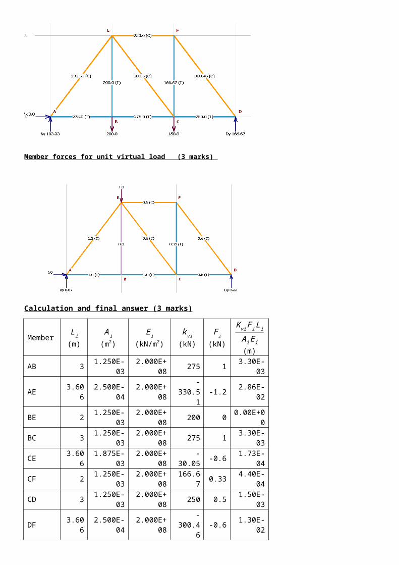
Member forces for unit virtual load (3 marks)
Calculation and final answer (3 marks)
MemberLi
(m)Ai
(m2)Ei
(kN/m2)k vi
(kN)F i
(kN)
K vi Fi LiA iE i(m)
AB 3 1.250E-03 2.000E+08 275 1 3.30E-03AE 3.606 2.500E-04 2.000E+08 -330.51 -1.2 2.86E-02BE 2 1.250E-03 2.000E+08 200 0 0.00E+00BC 3 1.250E-03 2.000E+08 275 1 3.30E-03CE 3.606 1.875E-03 2.000E+08 -30.05 -0.6 1.73E-04CF 2 1.250E-03 2.000E+08 166.67 0.33 4.40E-04CD 3 1.250E-03 2.000E+08 250 0.5 1.50E-03DF 3.606 2.500E-04 2.000E+08 -300.46 -0.6 1.30E-02EF 3 1.875E-03 2.000E+08 -250 -0.5 1.00E-03
TOTAL
0.051319
Vertical Displacement of E is 0.05132m or 51.32mm
OR
22.(b). Find the vertical displacement of joint ‘J1’ of the plane truss subjected to the load as shown in fig. 3. The figures in the parenthesis show the area of cross section of the members in mm2. Take E=200 GPa. (10)
Reactions for real load (1 marks) VA = 200kN↑ , VC = 0kN , HA = 400kN→ and HC = 400kN← .
Member forces for real load (3 marks)
Member forces for unit virtual load (3 marks)
Calculation and final answer (3 marks)
MemberLi
(m)Ai
(m2)Ei
(kN/m2)F i
(kN)k vi
(kN)
K vi Fi LiA iE i(m)
1 2 8.00E-05 2.00E+08 400 2 1.000E-012 2.236 1.20E-04 2.00E+08 -447.21 -2.236 9.316E-023 1 4.00E-05 2.00E+08 0 0 0.000E+004 2 8.00E-05 2.00E+08 400 2 1.000E-015 2.236 4.00E-05 2.00E+08 0 0 0.000E+006 2.236 1.20E-04 2.00E+08 -447.21 -2.236 9.316E-02
TOTAL 3.863E-01
Vertical Displacement of E is .3863 m or 38.63 cm downward

x1 x2
1 2x1 x2
L
BL/4 D
x1 x2
(+)
(+)
(+)
(-)
23.(a). Using principle of virtual work, find the deflection and slope at quarter span of simply supported beam of span of span ‘L’ when loaded with udl of intensity w/unit length throughout the span. (10)
From the principle of virtual work, the virtual work equation is
1.∆=∫ mMdxEI
For this problem
1.∆= ∫0
0.25L m1M1dx1EI
+ ∫0
0.75 L m2M 2dx2EI
Substituting and integrating:
1.∆= ∫0
0.25L 0.75 x1(wL2 x1−w x12
2 )dx1EI
+ ∫0
0.75L 0.25 x2(wL2 x2−w x22
2 )dx2EI
1.∆= 13w L4
8192 EI+ 63w L
4
8192EI = 19w L
4
2048EI
From the principle of virtual work, the virtual work equation is
BMD due to unit virtual load at D
RA=0.75kNRB=0.25kNm1 = 0.75 x1 0 ≤ x1 ≤ 0 .25Lm2 = 0.25 x2 0 ≤ x2 ≤ 0.75L
BMD due to given real load
RA=
RB=
M1 = 0 ≤ x1 ≤ 0.25L
M2 = 0 ≤ x2 ≤
BMD due to unit virtual moment at D
RA=1/L kNRB=-1/L kNm1θ = x1/L 0 ≤ x1 ≤ 0 .25Lm2θ = -x2/L 0 ≤ x2 ≤ 0.75L
Deflection at the quarter span is ∆= 19w L4
2048EI

BMD due to given real loadM1 = 0 ≤ x1 ≤ L
M2 = 0 ≤ x2 ≤
x1
12
x2 x1
x1(+)
(+)
(+)
(+)
x2
x2
L L
2EI EI
P
BA
Fig. 4
1.θ=∫ mθM dxEI
For this problem
1.θ ∫0
0.25L m1θM 1dx1EI
+ ∫0
0.75L m2θM 2dx2EI
Substituting and integrating:
1.θ ∫0
0.25Lx1L (wL2 x1−w x1
2
2 )dx1EI
+ ∫0
0.75L (−x2L )( wL2 x2−w x22
2 )dx2EI
1.θ= 13w L3
6144 EI− 63w L3
2048 EI = −11w L
3
384 EI
OR
23.(b). Using the method of virtual work, determine the deflection and slope at the free end of the cantilever beam shown in fig. 4. (10)
From the principle of virtual work, the virtual work equation is
Slope at the quarter span is θ¿−11w L3
384 EI = -0.0286 w L
3
EI radians
(-) means clockwise rotation.

1.∆=∫ mMdxEI
For this problem
1.∆=∫0
L m1M 1dx1EI
+∫0
L m2M 2dx22EI
Substituting and integrating:
1.∆=∫0
L −x1 (−Px1 )dx1EI
+∫0
L
−(L+x2)¿¿¿
1.∆=P L3
3 EI+ 7w L
3
6 EI = 3P L
3
2EI
From the principle of virtual work, the virtual work equation is
1.θ=∫mθM dxEI
For this problem
1.θ∫0
L m1θM 1dx1EI
+∫0
L m2θM2dx22EI
Substituting and integrating:
1.θ∫0
L 1. (−Px1 )dx1EI
+∫0
L 1. (−P(L+x2))dx22EI
1.θ=−P L2
2 EI+−3P L2
4 EI = −5P L
2
4 EI
Deflection at the quarter span is ∆=3P L3
2EI
Slope at the quarter span is θ¿−5 P L2
4 EI = -1.25 P L
2
EI
(-) means clockwise rotation.

25kN
2m
2m
6m
2I
II
A
B C
D
Fig. 5
24.(a). Determine the horizontal displacement at support D of the frame shown in fig. 5. Relative I values are indicated along the members. E=200x106 kN/m2 and I = 300x10-6 m4. Use the principle of virtual work. (10)
From the principle of virtual work, the virtual work equation is
1.∆=∫ mMdxEI
For this problem
1.∆=∫0
4 m1M 1dx1EI
+∫0
6 m2M 2dx22EI
+∫0
2 m3M3dx3EI
+∫0
2 m4M 4dx4EI
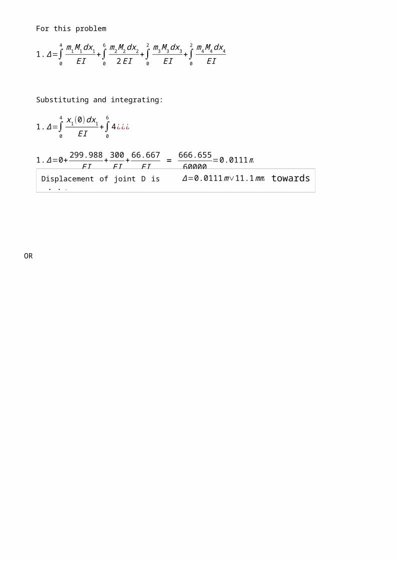
Substituting and integrating:
1.∆=∫0
4 x1(0)dx1EI
+∫0
6
4 ¿¿¿
1.∆=0+ 299.988EI
+ 300EI
+ 66.667EI = 666.65560000
=0.0111m
BMD due to unit virtual load at D
HA=1kN ←VA=0kNVD=0kNm1 = x1 0 ≤ x1 ≤ 4m2 = 4 kNm 0 ≤ x2 ≤ 6m3 =1(2+x3) 0 ≤ x3 ≤2m4 = 1( x4) 0 ≤ x4 ≤ 2
BMD due to given real load
HA=25kN ←VA=8.333kN↓VD=8.333kN↑M1 = 0 0 ≤ x1 ≤ 4M2 = 8.333 x2 0 ≤ x2 ≤ 6M3 =25(2+x3)-25x3 =50kNm 0 ≤ x3 ≤ 2M4 = 25 x4 0 ≤ x4 ≤ 2
1
2
3
4x1
x2
x3
x4
Displacement of joint D is ∆=0.0111m∨11.1mm towards right.

OR

2
1x2
x1Fig. 6
4 m
30kN
6 m2I
I
24.(b). Using the method of virtual work, find the vertical deflection and slope at the free end of the post shown in Fig. 6. E=200kN/mm2, I = 40x106 mm4. (10)
From the principle of virtual work, the virtual work equation is
1.∆=∫ mMdxEI
For this problem
1.∆=∫0
L m1M 1dx1EI
+∫0
L m2M 2dx22EI
Substituting and integrating:
1.∆=∫0
4 −x1 (−30 x1 )dx1EI
+∫0
6 −4 (−120 ) dx22 EI
1.∆=640EI
+ 1440EI = 2080EI = 20808000
=0.26m=260mm
From the principle of virtual work, the virtual work equation is
1.θ=∫mθM dxEI
For this problem
1.θ∫0
L m1θM 1dx1EI
+∫0
L m2θM2dx22EI
BMD due to unit virtual load at free end
m1 = -x1 0 ≤ x1 ≤ 4m2 = -4 0 ≤ x2 ≤ 6
BMD due to given real load
M1 = −30 x1 0 ≤ x1 ≤ 4
M2 = −30×4=−120kNm 0 ≤ x2 ≤ 6
BMD due to unit virtual moment at free end
m1θ = 1 0 ≤ x1 ≤4m2θ = 1 0 ≤ x2 ≤ 6
Deflection at the free end is ∆=260mm
EI= 200×106 × 40x106 x 10-12=8000
21kN 60kN 80kN 40kN
3m 2m 2m
16m
BA
Substituting and integrating:
1.θ∫0
4 1. (−30 x1 )dx1EI
+∫0
6 1. (−120 ) dx22EI
1.θ=−240EI
+−360EI = −600EI =¿−600
8000=−0.075 radians
25.(a). A train of concentrated loads shown in figure below moves from left to right with a lead load 40kN on a simply supported girder of span 16m.
Determine the absolute maximum shear force and absolute maximum bending moment developed in the beam.(10)
For determining absolute max BM
Step 1 Critical load. Left span = 8m and right span 8m
S.No. Load on left span (kN)Avg load on left span
Avg load on Right span
Load on right span (kN)
1
21+60+80+40 =201 25.125 0 0 = 0
2 21+60+80 =161 20.125 5 40 = 40
3 21+60 = 81 10.125 20 80+40 = 100
4 21 = 21 2.625 22.5 60+80+40 = 180
5 0 = 0 0 25.125 21+60+80+40 =201
The 80kN is the critical load
Step 2 – Resultant load and its location
Slope at the quarter span is θ¿−0.075 radians
(-) means clockwise rotation.

R
0.7214m
4.2786m
21kN 60kN 80kN 40kN
3m 2m 2m
0.3607m
4.6393m
21kN 60kN 80kN 40kN
3m 2m 2m
x=(21×0) (60×3 )+(80×5 )+(40×7 )
21+60+80+40 =860201=4.2786m
from left end of the load system.
Step 3 – Position the load system
Step 4 – Calculate the BM under the critical load which is at 8.3607m from left end.
BM under the critical load = (21*1.6046)+(60*3.0370)+(80*3.9919)+(40*2.9468) = 653.14 kNm
16m
BA
ILD for BM under critical load (at 8.3607m from left).
Ordinates under the loads are shown
3.03701.6046
3.9919 2.9468
3.3607m 5.6393m
8m
c = 0.7214m [distance between Resultant and critical load]
R
0.7214m
4.2786m
0.3607m
4.6393m
Midpoint between resultant and the critical load
midspan

OR
25.(b). A simply supported beam has a span of 15m and is subjected to a 5 m long uniformly distributed load of 40kN/m, traversing along the span from left to right. Draw influence line diagram for shear force and bending moment at a section 6m from left end. Use the influence diagrams to calculate the maximum shear force and maximum bending moment at this section. (10)
Absolute Bending moment is 653.14 kNm


*************** END ****************