Embed Size (px)
Citation preview
IOP PUBLISHING SMART MATERIALS AND STRUCTURES
Smart Mater. Struct. 16 (2007) 1277–1284 doi:10.1088/0964-1726/16/4/040
A rotational joint for shape morphingspace truss structuresA Y N Sofla, D M Elzey and H N G Wadley
Materials Science and Engineering Department, University of Virginia, Charlottesville,VA 22904, USA
E-mail: [email protected] (A Y N Sofla)
Received 28 November 2006, in final form 10 June 2007Published 5 July 2007Online at stacks.iop.org/SMS/16/1277
AbstractA rotational joint is introduced for use in shape morphing or deployablespace truss structures. The joint is a chain mechanism comprising up to sixpivoted linkages that provide a compact mechanism for the connection of upto six structures at a node. The total number of degrees of freedom for aconstrained joint mechanism with six links is found. A closed chain model isthen used to determine the angle between the adjacent links as the structure ischanged during shape morphing. The limiting pivot rotation angle isestablished by physical interference and is determined for a model problem.
(Some figures in this article are in colour only in the electronic version)
1. Introduction
Space truss structures consist of truss members (struts) joinedat nodes [1]. The nodes restrict axial movement of the truss andimpede truss rotation at the nodes. This rotational resistancecould be a significant limitation for actuated truss structuresin which some trusses are replaced by linear displacementactuators. To illustrate, consider a simple, tetrahedral three-dimensional (3D) truss structure supported on one of itstriangular sides by a foundation, figure 1(a). The number ofinextensional mechanisms, M , of such a pin-jointed structureis given by Maxwell’s stability criterion, which relates thenumber of non-foundation joints ( j ) and non-foundation trussmembers (b) to M [2]. The three-dimensional form of thecriterion applicable to the tetrahedral shown in figure 1 can bewritten:
M = 3 j − b. (1)
For the pin-jointed truss structure shown in figure 1(a), b = 3and j = 1 (one of the triangles consisting of three nodes andthree bars is the foundation). In this case, M = 0, whichdefines a statically determinate structure. If an external loadis therefore applied to the structure, the force in every strut canbe determined from the equations of mechanical equilibriumat the nodes. The structure is also kinematically determinatesince the location of the joints can also be uniquely determined.If M has a positive value, the structure is kinematicallyindeterminate and the location of one or more nodes can thenno longer be uniquely determined by the length of the trusses.
Removing one of the non-foundation trusses of thestatically determinate structure, figure 1(b), results in astructure that behaves as a mechanism with one degree offreedom (M = 1). Replacing the removed truss with anextensional actuator can restore the static determinacy of thetetrahedral truss structure and allows it to then exhibit shapechanging behavior provided the nodes marked 1 and 2 infigure 1(b) have a rotational degree of freedom. Such structureshave attracted recent interest for shape morphing applicationssince they do not develop states of self stress when shapechanges are caused to occur by longitudinal deformations ofthe linear actuator [3]. They are therefore candidates for highauthority, shape morphing systems.
The very simple statically determinate system shown infigure 1(a) is of limited utility for smart structures. However,Hutchinson et al [4] have identified a 3D kagome ‘plate like’truss structure in which the trusses are connected by pin jointswith no rotational resistance, figure 2. This structure has beenconverted to a shape morphing truss plate by replacing some ofthe trusses with linear actuators.
Unfortunately the trusses in such space truss structuresare connected at nodes by either welding or by mechanicalfastening (for example by screwing the trusses to a sphericalnode) and they are unable to rotate about the node.Deformation of the truss (induced by the actuators) then resultsin either elastic or/and plastic deformation near these joints.The storage of strain energy at the joints limits the shapemorphing capability of the plate and repeated cycling of the
0964-1726/07/041277+08$30.00 © 2007 IOP Publishing Ltd Printed in the UK 1277
A Y N Sofla et al
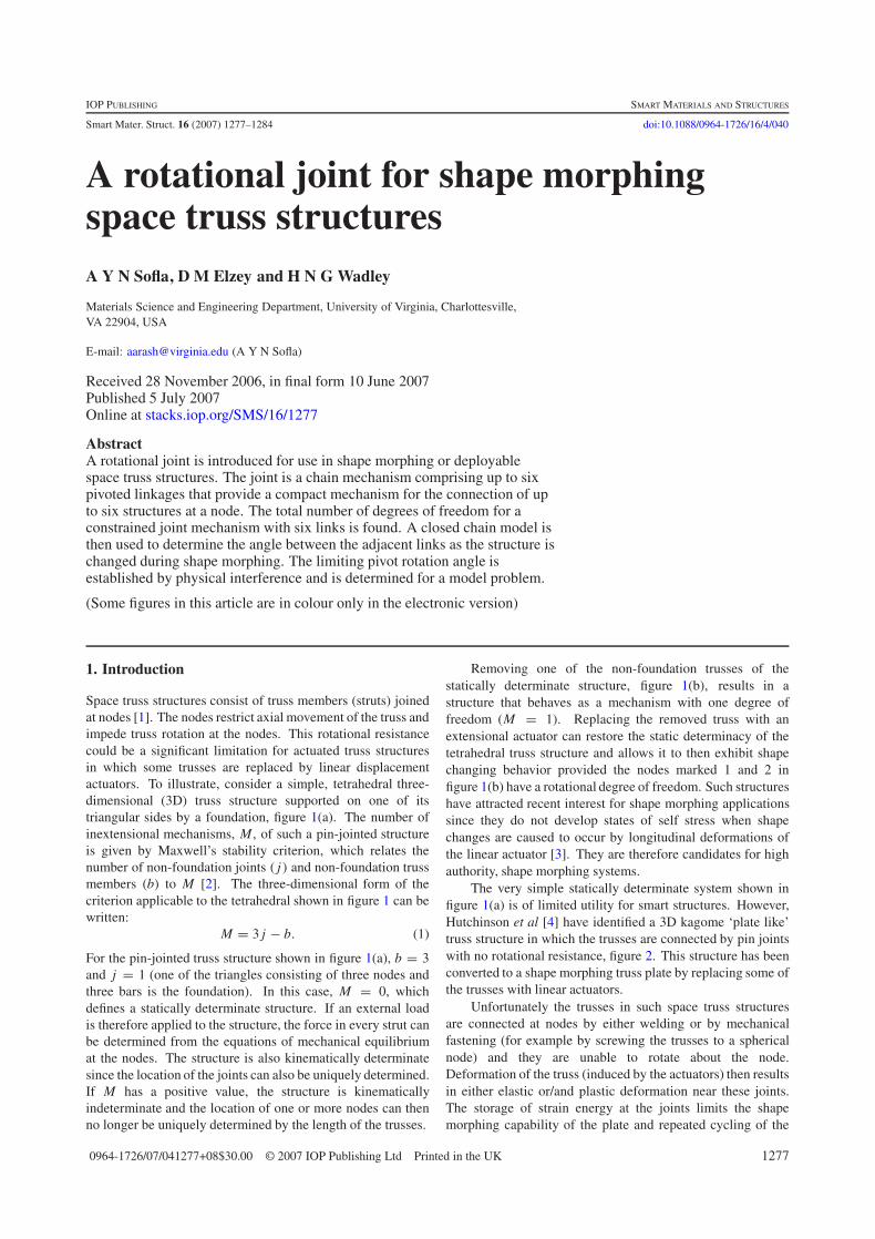
Figure 1. A tetrahedral space truss unit attached on one side to arigid foundation. (a) A pin-jointed statically determinate truss.(b) Elimination of one truss member changes the structure to amechanism provided nodes 1 and 2 permit rotational degrees offreedom.
Figure 2. Example of a 3D kagome plate for shape morphing platestructure [4]. The welded node construction causes stresses todevelop in the trusses during actuation. This limits actuationauthority and increases the susceptibility of the structure to failure byfatigue.
structure’s shape could lead to premature failure by fatigue.Shape morphing structures of this type could therefore beimproved if the trusses were connected using nodes that hada low rotational resistance.
In general, connecting more than two moving trusses orlinkages to a single joint complicates the mechanical designand associated fabrication processes. For instance, two rodsmay be connected by a spherical joint with three degrees offreedom. Such ball joints are relatively easy to manufactureand designs are available as spherical bearings. Howeveradding only one more link to a two-rod ball joint in sucha way that the new member possesses at least one degreeof freedom makes the design considerably more complicated.The earliest multilink joint design appears to be that used invariable geometry truss (VGT) structures [5]. A VGT structureis a statically determinate truss with tetrahedral, octahedral orother simple geometric unit cells. The truss structure’s shapecan be varied by changing the length of some of the struts.Two of the trusses in the VGT structure’s joint are directlyhinged to a main hub while four others are hinged to twopivots which can rotate with respect to the hub [6]. Such ajoint is an example of an open chain mechanism [7]. The trussrotation angle is limited by the physical interference betweentruss members at the joint. The trusses connections are usuallyoffset at the joint and do not therefore intersect at a single point,making analysis of the joint quite complicated.
A few other approaches for multi-truss rotational connec-tion have been proposed. Stewart platform type mechanisms
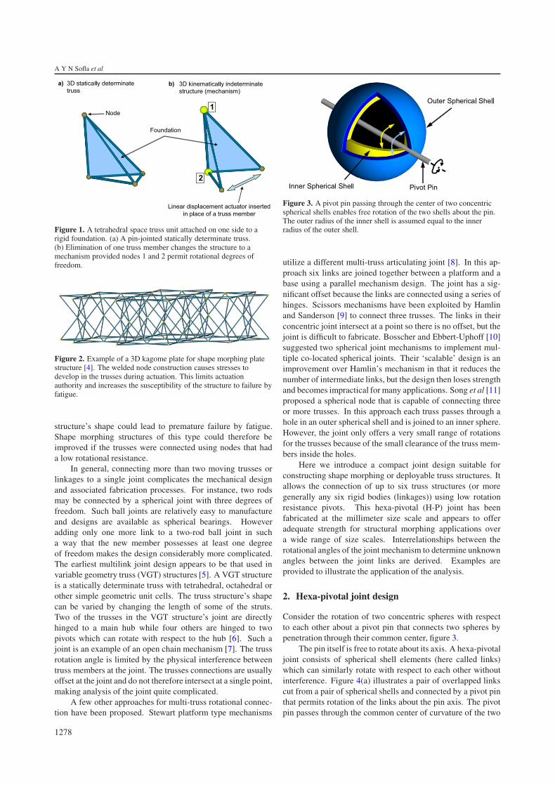
Figure 3. A pivot pin passing through the center of two concentricspherical shells enables free rotation of the two shells about the pin.The outer radius of the inner shell is assumed equal to the innerradius of the outer shell.
utilize a different multi-truss articulating joint [8]. In this ap-proach six links are joined together between a platform and abase using a parallel mechanism design. The joint has a sig-nificant offset because the links are connected using a series ofhinges. Scissors mechanisms have been exploited by Hamlinand Sanderson [9] to connect three trusses. The links in theirconcentric joint intersect at a point so there is no offset, but thejoint is difficult to fabricate. Bosscher and Ebbert-Uphoff [10]suggested two spherical joint mechanisms to implement mul-tiple co-located spherical joints. Their ‘scalable’ design is animprovement over Hamlin’s mechanism in that it reduces thenumber of intermediate links, but the design then loses strengthand becomes impractical for many applications. Song et al [11]proposed a spherical node that is capable of connecting threeor more trusses. In this approach each truss passes through ahole in an outer spherical shell and is joined to an inner sphere.However, the joint only offers a very small range of rotationsfor the trusses because of the small clearance of the truss mem-bers inside the holes.
Here we introduce a compact joint design suitable forconstructing shape morphing or deployable truss structures. Itallows the connection of up to six truss structures (or moregenerally any six rigid bodies (linkages)) using low rotationresistance pivots. This hexa-pivotal (H-P) joint has beenfabricated at the millimeter size scale and appears to offeradequate strength for structural morphing applications overa wide range of size scales. Interrelationships between therotational angles of the joint mechanism to determine unknownangles between the joint links are derived. Examples areprovided to illustrate the application of the analysis.
2. Hexa-pivotal joint design
Consider the rotation of two concentric spheres with respectto each other about a pivot pin that connects two spheres bypenetration through their common center, figure 3.
The pin itself is free to rotate about its axis. A hexa-pivotaljoint consists of spherical shell elements (here called links)which can similarly rotate with respect to each other withoutinterference. Figure 4(a) illustrates a pair of overlapped linkscut from a pair of spherical shells and connected by a pivot pinthat permits rotation of the links about the pin axis. The pivotpin passes through the common center of curvature of the two
1278
A rotational joint for shape morphing space truss structures
Figure 4. (a) Two concentric spherical links can be cut fromspherical shells. Both links can freely rotate about the common pivotpin though the axial movement of the links is restricted (viamechanical retainers). (b) A hexa-pivotal joint consisting of sixspherical links (L1 − L6) held in position using six pivoting pins(P1 − P6). Two trusses (not shown) can be attached to each link. Thejoint is shown with all the pivot pins lying in a common plane.
links. To ensure that the links remain in sliding contact, theyare fabricated from spherical shells, where the outer radius ofthe smaller sphere is equal to the inner radius of the larger one.The spherical shell links are free to rotate about the pin but arerestricted from moving axially along the pin by axial retainers(e.g. a cotter or ring and grooved pin).
A spatial closed chain mechanism (the links form a closedloop) can be formed by sequentially connecting six sphericalshell links, figure 4(b). This closed mechanism is referredto as a hexa-pivotal joint. Although a closed chain H-P jointis considered here, the joint can be used as an open chainmechanism by disengaging any of the pivots or by using asimilar mechanism with fewer than six links. An open chainjoint has more total degrees of freedom but loses strength.
Although a joint can conceptually consist of two or morespherical links, here we are interested in a joint with six links:three inner and three outer links with a common radius ofcurvature at their contacting surfaces. The H-P joint can beused to connect 12 truss members, labeled T 1–T 12, figure 5.The trusses can be fixed to the spherical shell links by eithermechanical attachment or by welding. The pivot pins can alsobe used as truss members although they must be permitted tofreely rotate about their longitudinal axis.
Figure 5. A hexa-pivotal joint with 12 truss members (T 1–T 12)attached. In practice the trusses can be rigidly fixed to the links bymechanical fasteners or by welding.
3. Kinematic analysis
A closed chain hexa-pivotal joint is a constrained mechanismin which six links are connected by six revolute joints (pivots).Moving any link in the mechanism, as during shape morphing,can cause the other links to be reconfigured. The new shapeof the closed chain H-P joint can be uniquely defined from therotation angles of adjacent pairs of links about the commonrevolute joint of each pair. Therefore, in the shape morphingapplications using the H-P joint, the shape of the structurecan be controlled by actuators which control the rotation anglebetween the adjacent links.
The number of actuators acting on a single H-P jointmust be equal to the total degrees of freedom of the H-Pjoint. Although there are six angular rotations between theadjacent spherical linkages (because there is a total of six pivotsin the H-P joint), the number of degrees of freedom of theclosed chain mechanism needs to be determined. For a generalspherical linkage in which each of the links is constrained torotate about the same fixed point in space, the mobility, F , isgiven by the number of links and revolute joints [7]:
F = 3(n − 1) − 2p, (2)
where n is the number of links and p is the number of revolutejoints. For the H-P joint, n = 6 and p = 6, so the total degreesof freedom of the assembly is three. Therefore, controllingthree (out of six) rotation angles of the adjacent sphericallinks can uniquely determine the H-P joint shape. The threeunknown rotation angles of the H-P joint need to be found tofully determine the joint shape.
The six spherical links in H-P joint are labeled L1,L2, . . . , L6, figure 4(b). An adjacent pair of links, e.g. Li−1
and Li , are hinged by a pivot pin, Pi . A flat joint shape,figure 4(b), results when the axis of all six pivot pins lie inthe plane. The relative rotation angle of a pair of adjacentlinks, Li−1 and Li , about their common revolute joint, Pi , isdenoted θi (note that L6 precedes L1 in the closed chain andthe angle is denoted θ1; see figure 6). This angular rotation is
1279
A Y N Sofla et al
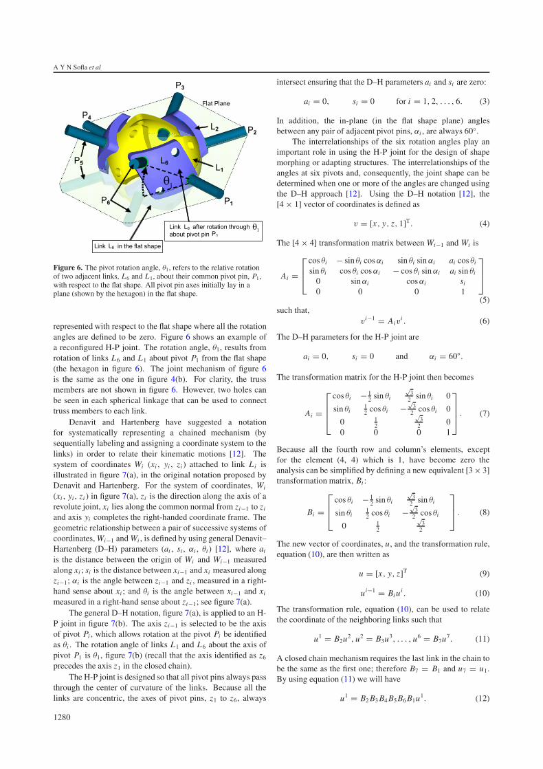
Figure 6. The pivot rotation angle, θ1, refers to the relative rotationof two adjacent links, L6 and L1, about their common pivot pin, P1,with respect to the flat shape. All pivot pin axes initially lay in aplane (shown by the hexagon) in the flat shape.
represented with respect to the flat shape where all the rotationangles are defined to be zero. Figure 6 shows an example ofa reconfigured H-P joint. The rotation angle, θ1, results fromrotation of links L6 and L1 about pivot P1 from the flat shape(the hexagon in figure 6). The joint mechanism of figure 6is the same as the one in figure 4(b). For clarity, the trussmembers are not shown in figure 6. However, two holes canbe seen in each spherical linkage that can be used to connecttruss members to each link.
Denavit and Hartenberg have suggested a notationfor systematically representing a chained mechanism (bysequentially labeling and assigning a coordinate system to thelinks) in order to relate their kinematic motions [12]. Thesystem of coordinates Wi (xi , yi , zi ) attached to link Li isillustrated in figure 7(a), in the original notation proposed byDenavit and Hartenberg. For the system of coordinates, Wi
(xi , yi , zi ) in figure 7(a), zi is the direction along the axis of arevolute joint, xi lies along the common normal from zi−1 to zi
and axis yi completes the right-handed coordinate frame. Thegeometric relationship between a pair of successive systems ofcoordinates, Wi−1 and Wi , is defined by using general Denavit–Hartenberg (D–H) parameters (ai , si , αi , θi ) [12], where ai
is the distance between the origin of Wi and Wi−1 measuredalong xi ; si is the distance between xi−1 and xi measured alongzi−1; αi is the angle between zi−1 and zi , measured in a right-hand sense about xi ; and θi is the angle between xi−1 and xi
measured in a right-hand sense about zi−1; see figure 7(a).The general D–H notation, figure 7(a), is applied to an H-
P joint in figure 7(b). The axis zi−1 is selected to be the axisof pivot Pi , which allows rotation at the pivot Pi be identifiedas θi . The rotation angle of links L1 and L6 about the axis ofpivot P1 is θ1, figure 7(b) (recall that the axis identified as z6
precedes the axis z1 in the closed chain).The H-P joint is designed so that all pivot pins always pass
through the center of curvature of the links. Because all thelinks are concentric, the axes of pivot pins, z1 to z6, always
intersect ensuring that the D–H parameters ai and si are zero:
ai = 0, si = 0 for i = 1, 2, . . . , 6. (3)
In addition, the in-plane (in the flat shape plane) anglesbetween any pair of adjacent pivot pins, αi , are always 60◦.
The interrelationships of the six rotation angles play animportant role in using the H-P joint for the design of shapemorphing or adapting structures. The interrelationships of theangles at six pivots and, consequently, the joint shape can bedetermined when one or more of the angles are changed usingthe D–H approach [12]. Using the D–H notation [12], the[4 × 1] vector of coordinates is defined as
v = [x, y, z, 1]T. (4)
The [4 × 4] transformation matrix between Wi−1 and Wi is
Ai =⎡⎢⎣
cos θi − sin θi cos αi sin θi sin αi ai cos θi
sin θi cos θi cos αi − cos θi sin αi ai sin θi
0 sin αi cos αi si
0 0 0 1
⎤⎥⎦
(5)such that,
vi−1 = Aivi . (6)
The D–H parameters for the H-P joint are
ai = 0, si = 0 and αi = 60◦.
The transformation matrix for the H-P joint then becomes
Ai =
⎡⎢⎢⎣
cos θi − 12 sin θi
√3
2 sin θi 0
sin θi12 cos θi −
√3
2 cos θi 0
0 12
√3
2 00 0 0 1
⎤⎥⎥⎦ . (7)
Because all the fourth row and column’s elements, exceptfor the element (4, 4) which is 1, have become zero theanalysis can be simplified by defining a new equivalent [3 × 3]transformation matrix, Bi :
Bi =⎡⎢⎣
cos θi − 12 sin θi
√3
2 sin θi
sin θi12 cos θi −
√3
2 cos θi
0 12
√3
2
⎤⎥⎦ . (8)
The new vector of coordinates, u, and the transformation rule,equation (10), are then written as
u = [x, y, z]T (9)
ui−1 = Bi ui . (10)
The transformation rule, equation (10), can be used to relatethe coordinate of the neighboring links such that
u1 = B2u2, u2 = B3u3, . . . , u6 = B7u7. (11)
A closed chain mechanism requires the last link in the chain tobe the same as the first one; therefore B7 = B1 and u7 = u1.By using equation (11) we will have
u1 = B2 B3 B4 B5 B6 B1u1. (12)
1280
A rotational joint for shape morphing space truss structures
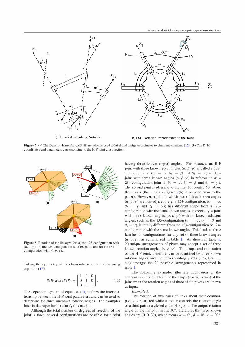
Figure 7. (a) The Denavit–Hartenberg (D–H) notation is used to label and assign coordinates to chain mechanisms [12]. (b) The D–Hcoordinates and parameters corresponding to the H-P joint cross section.
Figure 8. Rotation of the linkages for (a) the 123-configuration with(0, 0, γ ), (b) the 123-configuration with (0, β, 0), and (c) the 134configuration with (0, 0, γ ).
Taking the symmetry of the chain into account and by usingequation (12),
B1 B2 B3 B4 B5 B6 =[ 1 0 0
0 1 00 0 1
]. (13)
The dependent system of equation (13) defines the interrela-tionship between the H-P joint parameters and can be used todetermine the three unknown rotation angles. The exampleslater in the paper further clarify this method.
Although the total number of degrees of freedom of thejoint is three, several configurations are possible for a joint
having three known (input) angles. For instance, an H-Pjoint with three known pivot angles (α, β, γ ) is called a 123-configuration if (θ1 = α, θ2 = β and θ3 = γ ) while ajoint with three known angles (α, β, γ ) is referred to as a234-configuration joint if (θ2 = α, θ3 = β and θ4 = γ ).The second joint is identical to the first but rotated 60◦ aboutthe x axis (the x axis in figure 7(b) is perpendicular to thepaper). However, a joint in which two of three known angles(α, β, γ ) are non-adjacent (e.g. a 124-configuration, (θ1 = α,θ2 = β and θ4 = γ )) has different shape from a 123-configuration with the same known angles. Expectedly, a jointwith three known angles (α, β, γ ) with no known adjacentangles, such as the 135-configuration (θ1 = α, θ3 = β andθ5 = γ ), is totally different from the 123-configuration or 124-configuration with the same known angles. This leads to threefamilies of configurations for any set of three known angles(α, β, γ ), as summarized in table 1. As shown in table 1,20 unique arrangements of pivots may accept a set of threeknown rotation angles (α, β, γ ). The shape and orientationof the H-P joint, therefore, can be identified by three knownrotation angles and the corresponding pivots (123, 124, . . .,etc) amongst the 20 possible arrangements represented intable 1.
The following examples illustrate application of theanalysis in order to determine the shape (configuration) of thejoint when the rotation angles of three of six pivots are knownas input.
Example 1.The rotation of two pairs of links about their common
pivots is restricted while a motor controls the rotation angleof a third pair in a closed chain H-P joint. The output rotationangle of the motor is set at 30◦; therefore, the three knownangles are (0, 0, 30), which means α = 0◦, β = 0◦, γ = 30◦.
1281
A Y N Sofla et al
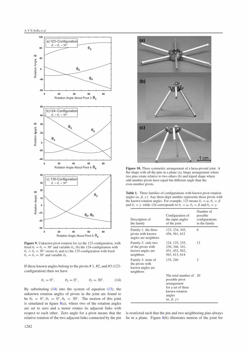
Figure 9. Unknown pivot rotation for (a) the 123-configuration, withfixed θ1 = θ2 = 30◦ and variable θ3, (b) the 124-configuration withθ1 = θ2 = 30◦ versus θ4 and (c) the 135-configuration with fixedθ1 = θ3 = 30◦ and variable θ5.
If these known angles belong to the pivots # 1, #2, and #3 (123-configuration) then we have
θ1 = 0◦, θ2 = 0◦, θ3 = 30◦. (14)
By substituting (14) into the system of equation (13), theunknown rotation angles of pivots in the joint are found tobe θ4 = 0◦, θ5 = 0◦, θ6 = 30◦. The motion of this jointis simulated in figure 8(a), where two of the rotation anglesare set to zero and a motor rotates its adjacent links withrespect to each other. Zero angle for a pivot means that therelative rotation of the two adjacent links connected by the pin
Figure 10. Three symmetric arrangement of a hexa-pivotal joint. Aflat shape with all the pins in a plane (a), hinge arrangement wheretwo pins rotate relative to two others (b) and tripod shape whereodd-number pivots have equal but different angle than theeven-number pivots.
Table 1. Three families of configurations with known pivot rotationangles (α, β, γ ). Any three-digit number represents those pivots withthe known rotation angles. For example, 123 means θ1 = α, θ2 = βand θ3 = γ while 124 corresponds to θ1 = α, θ2 = β and θ4 = γ .
Description ofthe family
Configuration ofthe input anglesof the joint
Number ofpossibleconfigurationsin the family
Family-1: the threepivots with knownangles are neighbors
123, 234, 345,456, 561, 612
6
Family-2: only twoof the pivots withknown angles areneighbors
124, 125, 235,236, 346, 341,451, 452, 562,563, 613, 614
12
Family-3: none ofthe pivots withknown angles areneighbors
135, 246 2
The total number ofpossible pivotarrangementfor a set of threeknown rotationangles(α, β, γ )
20
is restricted such that the pin and two neighboring pins alwayslie in a plane. Figure 8(b) illustrates motion of the joint for
1282
A rotational joint for shape morphing space truss structures
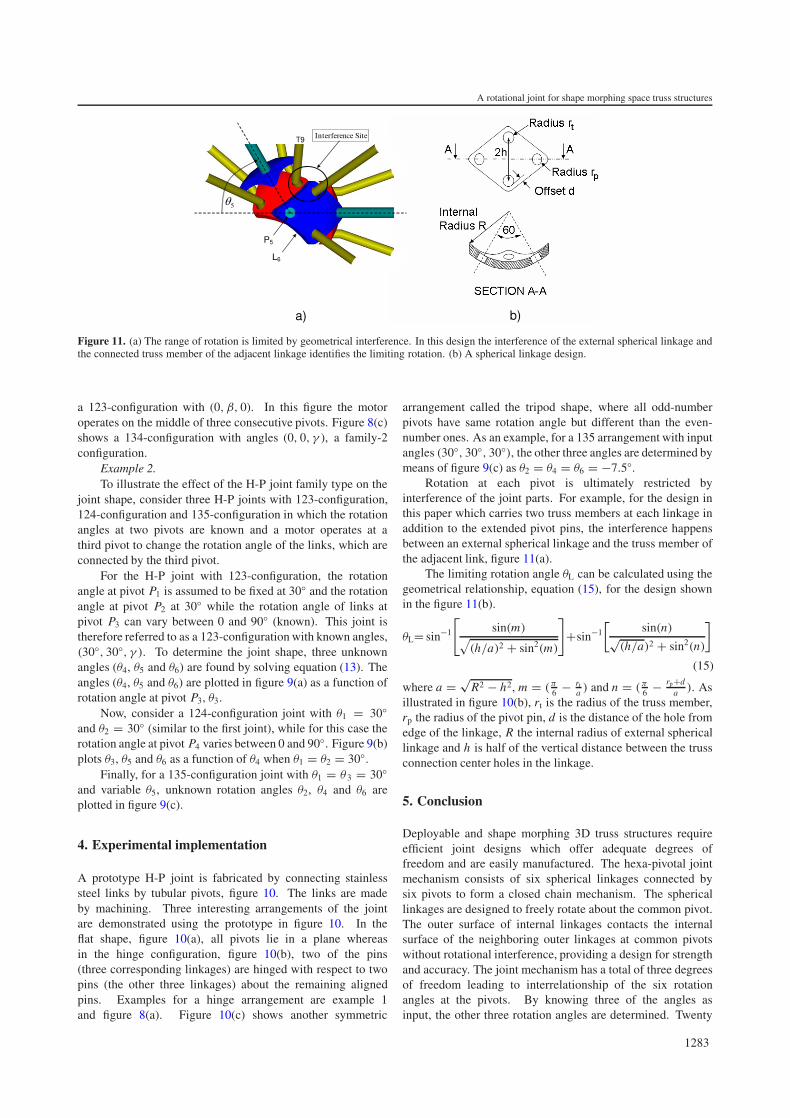
Figure 11. (a) The range of rotation is limited by geometrical interference. In this design the interference of the external spherical linkage andthe connected truss member of the adjacent linkage identifies the limiting rotation. (b) A spherical linkage design.
a 123-configuration with (0, β, 0). In this figure the motoroperates on the middle of three consecutive pivots. Figure 8(c)shows a 134-configuration with angles (0, 0, γ ), a family-2configuration.
Example 2.To illustrate the effect of the H-P joint family type on the
joint shape, consider three H-P joints with 123-configuration,124-configuration and 135-configuration in which the rotationangles at two pivots are known and a motor operates at athird pivot to change the rotation angle of the links, which areconnected by the third pivot.
For the H-P joint with 123-configuration, the rotationangle at pivot P1 is assumed to be fixed at 30◦ and the rotationangle at pivot P2 at 30◦ while the rotation angle of links atpivot P3 can vary between 0 and 90◦ (known). This joint istherefore referred to as a 123-configuration with known angles,(30◦, 30◦, γ ). To determine the joint shape, three unknownangles (θ4, θ5 and θ6) are found by solving equation (13). Theangles (θ4, θ5 and θ6) are plotted in figure 9(a) as a function ofrotation angle at pivot P3, θ3.
Now, consider a 124-configuration joint with θ1 = 30◦and θ2 = 30◦ (similar to the first joint), while for this case therotation angle at pivot P4 varies between 0 and 90◦. Figure 9(b)plots θ3, θ5 and θ6 as a function of θ4 when θ1 = θ2 = 30◦.
Finally, for a 135-configuration joint with θ1 = θ 3 = 30◦and variable θ5, unknown rotation angles θ2, θ4 and θ6 areplotted in figure 9(c).
4. Experimental implementation
A prototype H-P joint is fabricated by connecting stainlesssteel links by tubular pivots, figure 10. The links are madeby machining. Three interesting arrangements of the jointare demonstrated using the prototype in figure 10. In theflat shape, figure 10(a), all pivots lie in a plane whereasin the hinge configuration, figure 10(b), two of the pins(three corresponding linkages) are hinged with respect to twopins (the other three linkages) about the remaining alignedpins. Examples for a hinge arrangement are example 1and figure 8(a). Figure 10(c) shows another symmetric
arrangement called the tripod shape, where all odd-numberpivots have same rotation angle but different than the even-number ones. As an example, for a 135 arrangement with inputangles (30◦, 30◦, 30◦), the other three angles are determined bymeans of figure 9(c) as θ2 = θ4 = θ6 = −7.5◦.
Rotation at each pivot is ultimately restricted byinterference of the joint parts. For example, for the design inthis paper which carries two truss members at each linkage inaddition to the extended pivot pins, the interference happensbetween an external spherical linkage and the truss member ofthe adjacent link, figure 11(a).
The limiting rotation angle θL can be calculated using thegeometrical relationship, equation (15), for the design shownin the figure 11(b).
θL= sin−1
[sin(m)√
(h/a)2 + sin2(m)
]+sin−1
[sin(n)√
(h/a)2 + sin2(n)
]
(15)
where a = √R2 − h2, m = (π
6 − rta ) and n = (π
6 − rp+da ). As
illustrated in figure 10(b), rt is the radius of the truss member,rp the radius of the pivot pin, d is the distance of the hole fromedge of the linkage, R the internal radius of external sphericallinkage and h is half of the vertical distance between the trussconnection center holes in the linkage.
5. Conclusion
Deployable and shape morphing 3D truss structures requireefficient joint designs which offer adequate degrees offreedom and are easily manufactured. The hexa-pivotal jointmechanism consists of six spherical linkages connected bysix pivots to form a closed chain mechanism. The sphericallinkages are designed to freely rotate about the common pivot.The outer surface of internal linkages contacts the internalsurface of the neighboring outer linkages at common pivotswithout rotational interference, providing a design for strengthand accuracy. The joint mechanism has a total of three degreesof freedom leading to interrelationship of the six rotationangles at the pivots. By knowing three of the angles asinput, the other three rotation angles are determined. Twenty
1283
A Y N Sofla et al
different arrangements for the joint mechanism are possiblefor any set of three known angles, making the joint capableof having several different shapes. The hexa-pivotal joint iseasy to manufacture and can be fabricated to the desired sizeand strength. Having no offset between the links is anotheradvantage of the joint which makes it easily programmable forprecise positioning applications.
References[1] Connor J J 1976 Analysis of Structural Member Systems
(New York: The Ronald Press Company)[2] Maxwell J C 1864 On the calculation of the equilibrium and
stiffness of frames Phil. Mag. 27 294[3] Pellegrino S and Calladine C R 1986 Matrix analysis of
statically and kinematically indeterminate frameworks Int. J.Solids Struct. 22 409–28
[4] Hutchinson R G, Wicks N, Evans A G, Fleck N A andHutchinson J W 2003 Kagome plate structures for actuationInt. J. Solids Struct. 40 6969–80
[5] Padmanabhan B, Arun V and Reinholtz C F 1992 Closed forminverse kinematic analysis of variable-geometry trussmanipulators ASME J. Mech. Des. 114 438–43
[6] Hornett H C 1994 Joint for a variable geometry truss andmethod of constructing same Patent ApplicationLAR-15136-1 Serial No. 08/325,723 (Nasa LangleyResearch Center)
[7] McCarthy J M 2000 Geometric Design of Linkages(New York: Springer)
[8] Zanganeh K E and Angeles J 1994 Instantaneous kinematicsand design of a novel redundant parallel manipulator Proc.IEEE Int. Conf. on Robotics and Automation (San Diego,CA) pp 3043–8
[9] Hamlin G J and Snaderson A C 1998 Tetrobot: A ModularApproach to Reconfigurable Parallel Robotics(Norwell, MA: Kluwer)
[10] Bosscher P and Ebbert-Uphoff I 2003 A novel mechanism forimplementing multiple collocated spherical joints Proc.IEEE Int. Conf. on Robotics and Automation (Taipei,Taiwan) pp 336–41
[11] Song S, Kwon D and Kim W S 2001 Spherical joint forcoupling three or more links together at one point US PatentApplication 20010002964
[12] Denavit J and Hartenberg R S 1955 A kinematic notation forlower-pair mechanisms based on matrices ASME J. Appl.Mech. 22 215–21
1284