Embed Size (px)
Citation preview
Statics, Fourteenth EditionR.C. Hibbeler
Copyright ©2016 by Pearson Education, Inc.All rights reserved.
In-Class Activities:
• Check Homework, if any
• Reading Quiz
• Applications
• Simple Trusses
• Method of Joints
• Zero-force Members
• Concept Quiz
• Group Problem Solving
• Attention Quiz
Today’s Objectives:
Students will be able to:
a) Define a simple truss.
b) Determine forces in members of a
simple truss.
c) Identify zero-force members.
SIMPLE TRUSSES, THE METHOD OF JOINTS, & ZERO-FORCE MEMBERS
Statics, Fourteenth EditionR.C. Hibbeler
Copyright ©2016 by Pearson Education, Inc.All rights reserved.
1. One of the assumptions used when analyzing a simple truss is that
the members are joined together by __________.
A) Welding B) Bolting C) Riveting
D) Smooth pins E) Super glue
2. When using the method of joints, typically _________ equations of
equilibrium are applied at every joint.
A) Two B) Three
C) Four D) Six
READING QUIZ
Statics, Fourteenth EditionR.C. Hibbeler
Copyright ©2016 by Pearson Education, Inc.All rights reserved.
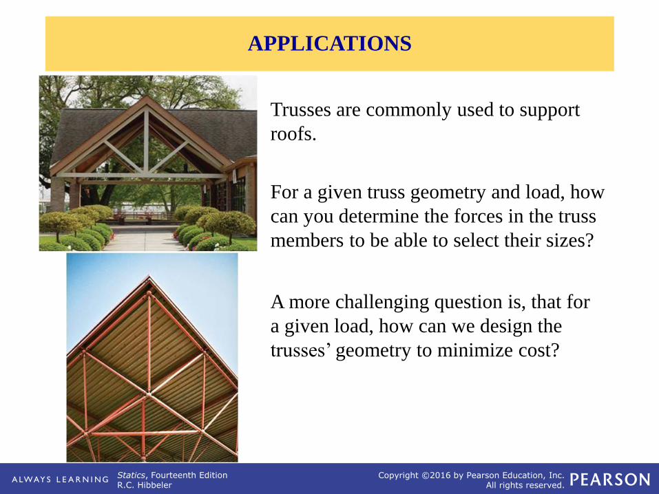
For a given truss geometry and load, how
can you determine the forces in the truss
members to be able to select their sizes?
Trusses are commonly used to support
roofs.
A more challenging question is, that for
a given load, how can we design the
trusses’ geometry to minimize cost?
APPLICATIONS
Statics, Fourteenth EditionR.C. Hibbeler
Copyright ©2016 by Pearson Education, Inc.All rights reserved.
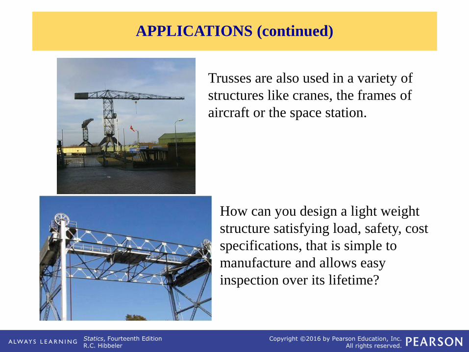
Trusses are also used in a variety of
structures like cranes, the frames of
aircraft or the space station.
How can you design a light weight
structure satisfying load, safety, cost
specifications, that is simple to
manufacture and allows easy
inspection over its lifetime?
APPLICATIONS (continued)
Statics, Fourteenth EditionR.C. Hibbeler
Copyright ©2016 by Pearson Education, Inc.All rights reserved.
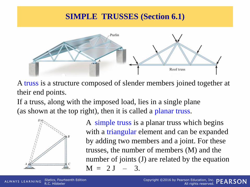
A simple truss is a planar truss which begins
with a triangular element and can be expanded
by adding two members and a joint. For these
trusses, the number of members (M) and the
number of joints (J) are related by the equation
M = 2 J – 3.
If a truss, along with the imposed load, lies in a single plane
(as shown at the top right), then it is called a planar truss.
A truss is a structure composed of slender members joined together at
their end points.
SIMPLE TRUSSES (Section 6.1)
Statics, Fourteenth EditionR.C. Hibbeler
Copyright ©2016 by Pearson Education, Inc.All rights reserved.
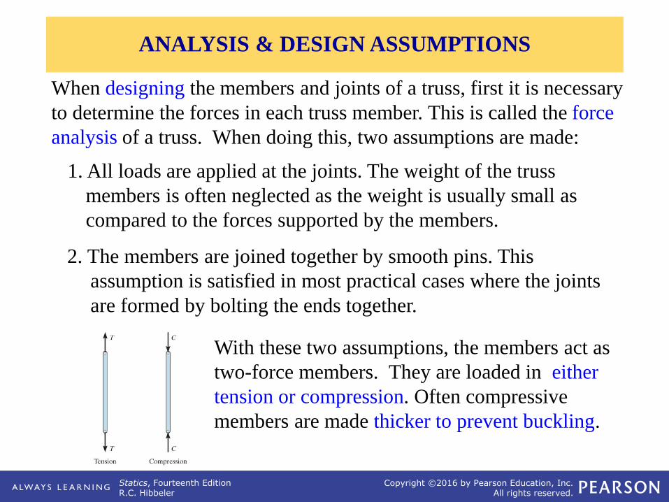
When designing the members and joints of a truss, first it is necessary
to determine the forces in each truss member. This is called the force
analysis of a truss. When doing this, two assumptions are made:
1. All loads are applied at the joints. The weight of the truss
members is often neglected as the weight is usually small as
compared to the forces supported by the members.
2. The members are joined together by smooth pins. This
assumption is satisfied in most practical cases where the joints
are formed by bolting the ends together.
With these two assumptions, the members act as
two-force members. They are loaded in either
tension or compression. Often compressive
members are made thicker to prevent buckling.
ANALYSIS & DESIGN ASSUMPTIONS
Statics, Fourteenth EditionR.C. Hibbeler
Copyright ©2016 by Pearson Education, Inc.All rights reserved.
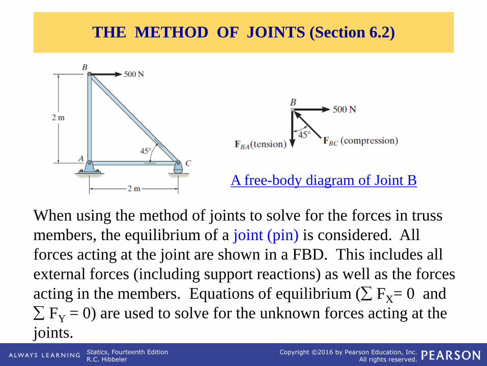
When using the method of joints to solve for the forces in truss
members, the equilibrium of a joint (pin) is considered. All
forces acting at the joint are shown in a FBD. This includes all
external forces (including support reactions) as well as the forces
acting in the members. Equations of equilibrium ( FX= 0 and
FY = 0) are used to solve for the unknown forces acting at the
joints.
A free-body diagram of Joint B
THE METHOD OF JOINTS (Section 6.2)
Statics, Fourteenth EditionR.C. Hibbeler
Copyright ©2016 by Pearson Education, Inc.All rights reserved.
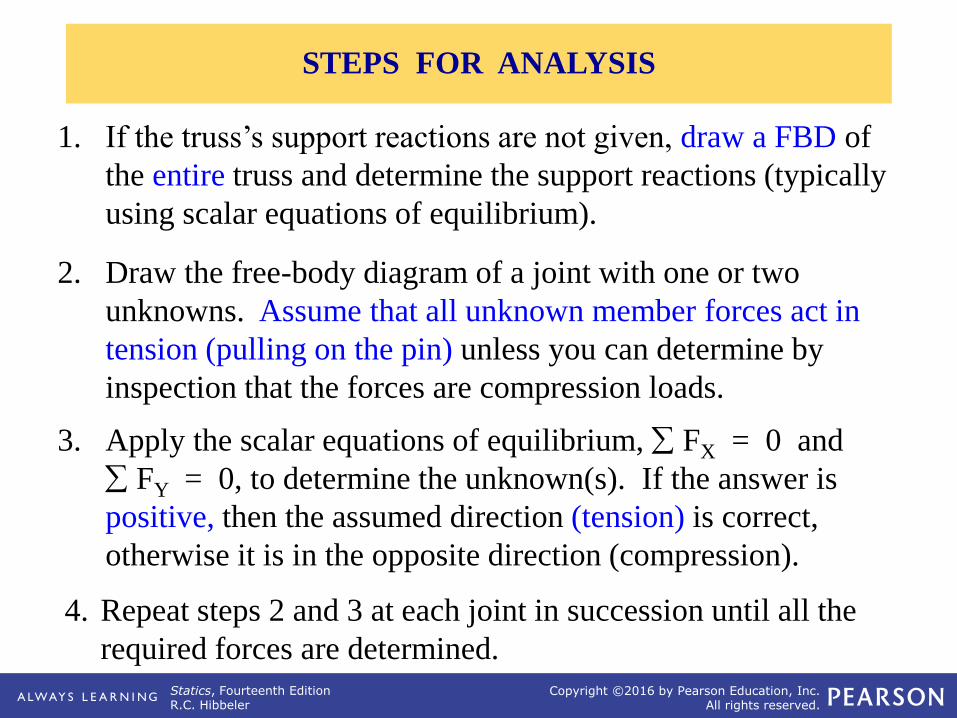
1. If the truss’s support reactions are not given, draw a FBD of
the entire truss and determine the support reactions (typically
using scalar equations of equilibrium).
2. Draw the free-body diagram of a joint with one or two
unknowns. Assume that all unknown member forces act in
tension (pulling on the pin) unless you can determine by
inspection that the forces are compression loads.
3. Apply the scalar equations of equilibrium, FX = 0 and
FY = 0, to determine the unknown(s). If the answer is
positive, then the assumed direction (tension) is correct,
otherwise it is in the opposite direction (compression).
4. Repeat steps 2 and 3 at each joint in succession until all the
required forces are determined.
STEPS FOR ANALYSIS
Statics, Fourteenth EditionR.C. Hibbeler
Copyright ©2016 by Pearson Education, Inc.All rights reserved.
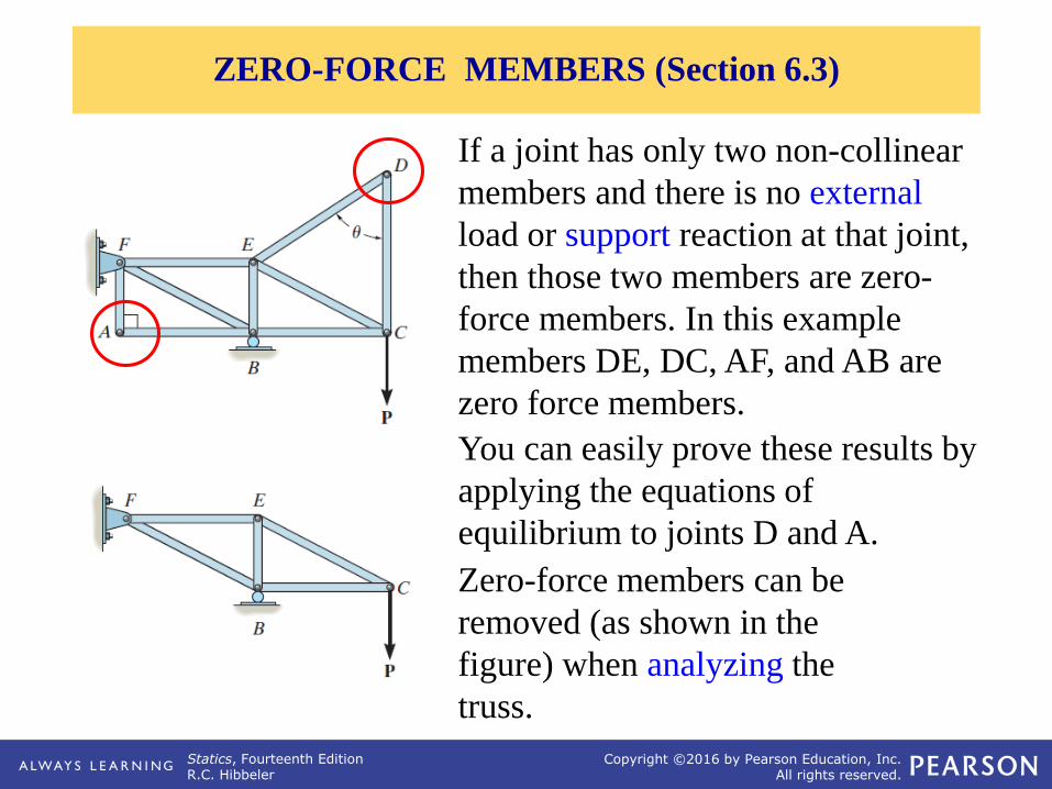
You can easily prove these results by
applying the equations of
equilibrium to joints D and A.
ZERO-FORCE MEMBERS (Section 6.3)
If a joint has only two non-collinear
members and there is no external
load or support reaction at that joint,
then those two members are zero-
force members. In this example
members DE, DC, AF, and AB are
zero force members.
Zero-force members can be
removed (as shown in the
figure) when analyzing the
truss.
Statics, Fourteenth EditionR.C. Hibbeler
Copyright ©2016 by Pearson Education, Inc.All rights reserved.
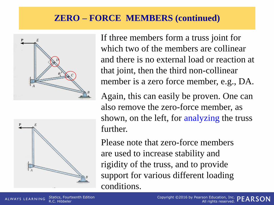
Again, this can easily be proven. One can
also remove the zero-force member, as
shown, on the left, for analyzing the truss
further.
Please note that zero-force members
are used to increase stability and
rigidity of the truss, and to provide
support for various different loading
conditions.
If three members form a truss joint for
which two of the members are collinear
and there is no external load or reaction at
that joint, then the third non-collinear
member is a zero force member, e.g., DA.
ZERO – FORCE MEMBERS (continued)
Statics, Fourteenth EditionR.C. Hibbeler
Copyright ©2016 by Pearson Education, Inc.All rights reserved.
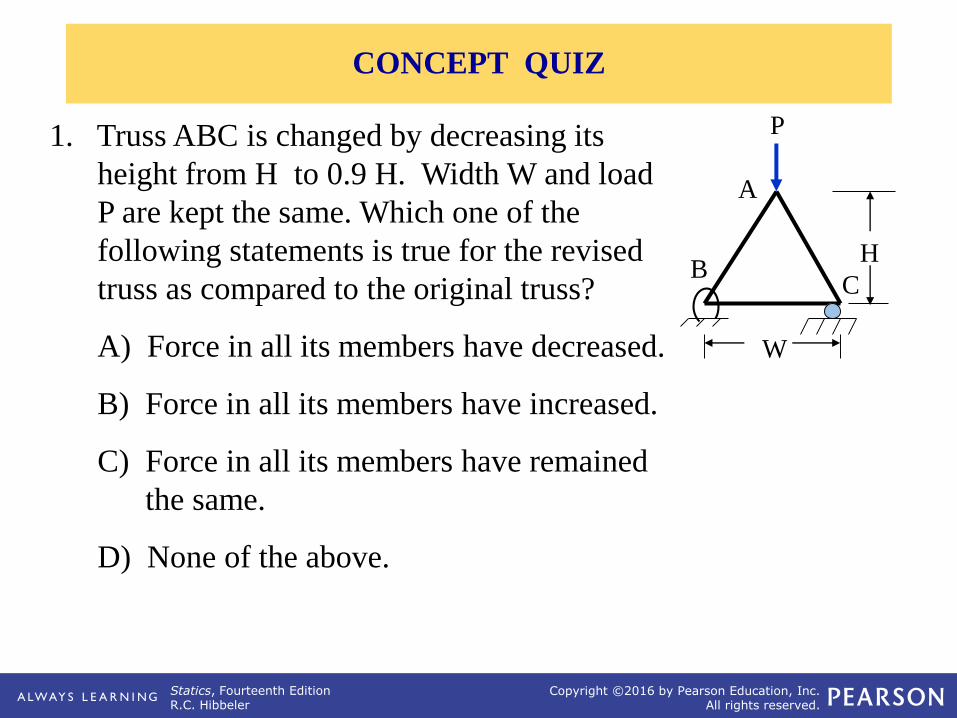
1. Truss ABC is changed by decreasing its
height from H to 0.9 H. Width W and load
P are kept the same. Which one of the
following statements is true for the revised
truss as compared to the original truss?
A) Force in all its members have decreased.
B) Force in all its members have increased.
C) Force in all its members have remained
the same.
D) None of the above.
C
H
P
A
B
W
CONCEPT QUIZ
Statics, Fourteenth EditionR.C. Hibbeler
Copyright ©2016 by Pearson Education, Inc.All rights reserved.
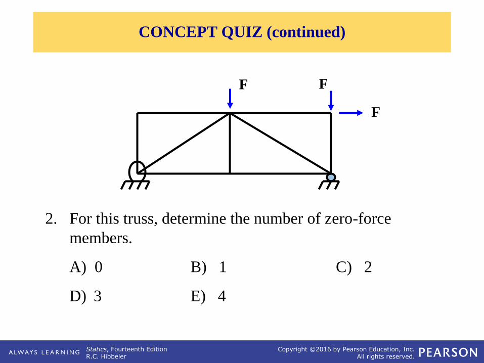
2. For this truss, determine the number of zero-force
members.
A) 0 B) 1 C) 2
D) 3 E) 4
F F
F
CONCEPT QUIZ (continued)
Statics, Fourteenth EditionR.C. Hibbeler
Copyright ©2016 by Pearson Education, Inc.All rights reserved.
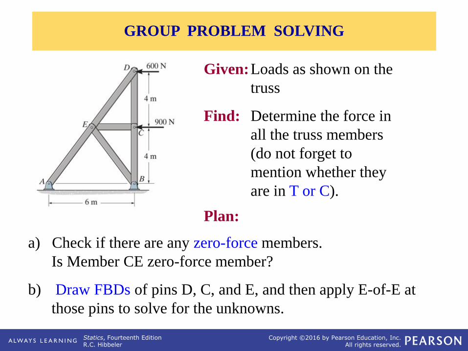
a) Check if there are any zero-force members.
Is Member CE zero-force member?
b) Draw FBDs of pins D, C, and E, and then apply E-of-E at
those pins to solve for the unknowns.
Given:Loads as shown on the
truss
Find: Determine the force in
all the truss members
(do not forget to
mention whether they
are in T or C).
Plan:
GROUP PROBLEM SOLVING
Statics, Fourteenth EditionR.C. Hibbeler
Copyright ©2016 by Pearson Education, Inc.All rights reserved.
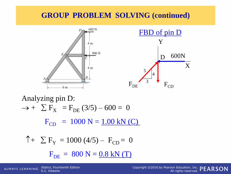
Analyzing pin D:
+ FX = FDE (3/5) – 600 = 0
FCD = 1000 N = 1.00 kN (C)
+ FY = 1000 (4/5) – FCD = 0
FDE = 800 N = 0.8 kN (T)
FBD of pin D
X
FCD
Y
D 600N
FDE3
45
GROUP PROBLEM SOLVING (continued)
Statics, Fourteenth EditionR.C. Hibbeler
Copyright ©2016 by Pearson Education, Inc.All rights reserved.
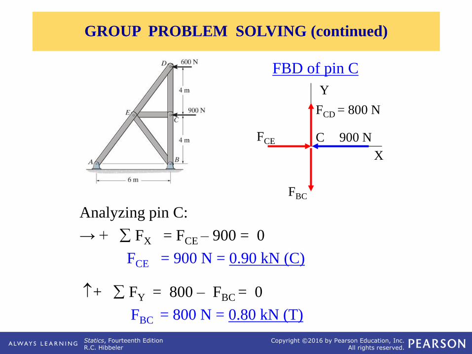
Analyzing pin C:
→ + FX = FCE – 900 = 0
FCE = 900 N = 0.90 kN (C)
+ FY = 800 – FBC = 0
FBC = 800 N = 0.80 kN (T)
FBD of pin C
900 N
X
FBC
Y
CFCE
FCD = 800 N
GROUP PROBLEM SOLVING (continued)
Statics, Fourteenth EditionR.C. Hibbeler
Copyright ©2016 by Pearson Education, Inc.All rights reserved.
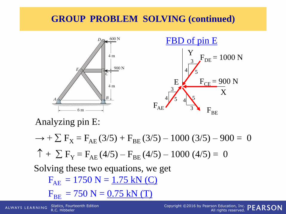
Analyzing pin E:
→ + FX = FAE (3/5) + FBE (3/5) – 1000 (3/5) – 900 = 0
+ FY = FAE (4/5) – FBE (4/5) – 1000 (4/5) = 0
Solving these two equations, we get
FAE = 1750 N = 1.75 kN (C)
FBE = 750 N = 0.75 kN (T)
FBD of pin E
FCE = 900 N
X
FAE
Y
E
FDE = 1000 N
FBE
3
4 5
3
4 5
3
4 5
GROUP PROBLEM SOLVING (continued)
Statics, Fourteenth EditionR.C. Hibbeler
Copyright ©2016 by Pearson Education, Inc.All rights reserved.
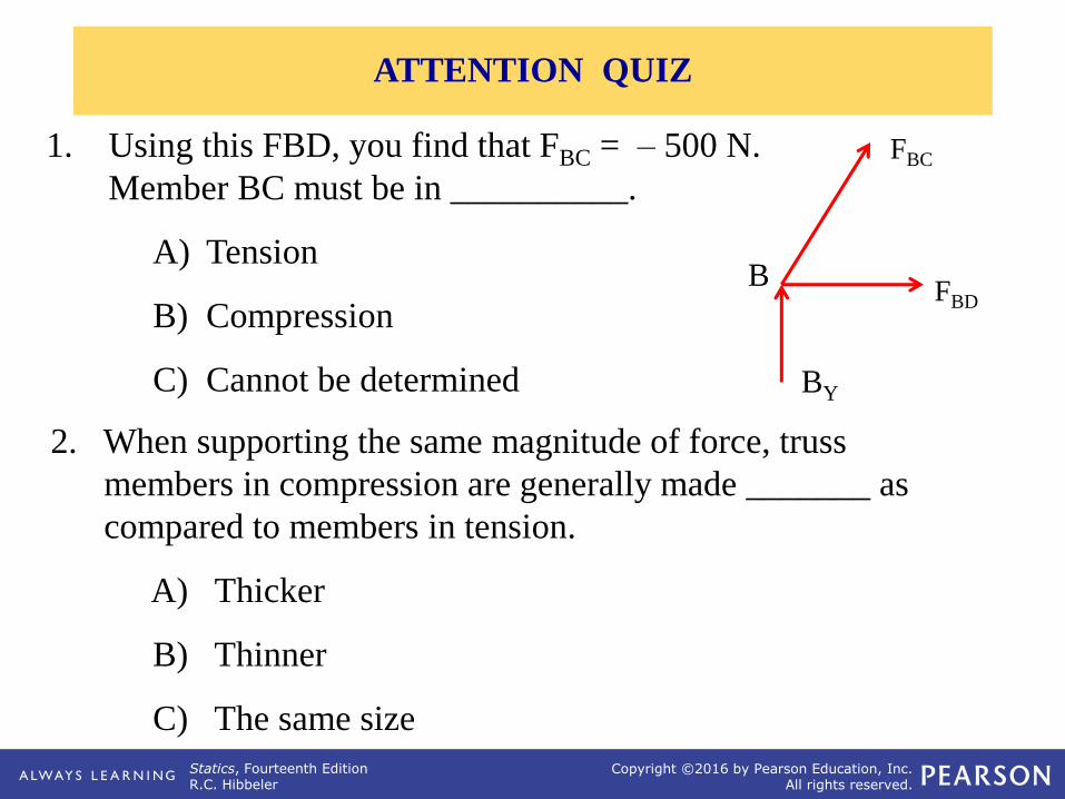
1. Using this FBD, you find that FBC = – 500 N.
Member BC must be in __________.
A) Tension
B) Compression
C) Cannot be determined
2. When supporting the same magnitude of force, truss
members in compression are generally made _______ as
compared to members in tension.
A) Thicker
B) Thinner
C) The same size
FBD
FBC
B
BY
ATTENTION QUIZ
Statics, Fourteenth EditionR.C. Hibbeler
Copyright ©2016 by Pearson Education, Inc.All rights reserved.