Embed Size (px)
Citation preview
International Research Journal of Engineering and Technology (IRJET) e-ISSN: 2395-0056
Volume: 08 Issue: 04 | Apr 2021 www.irjet.net p-ISSN: 2395-0072
© 2021, IRJET | Impact Factor value: 7.529 | ISO 9001:2008 Certified Journal | Page 2859
Vibration Monitoring of Turning CNC Machine Spindle
Rahul Sharma1, Purushottam Kumar Sahu2
1Research scholar BM College of Technology, Indore RGPV, Bhopal 2Professor, BM College of Technology, Indore RGPV, Bhopal
---------------------------------------------------------------------***----------------------------------------------------------------------Abstract All machines are designed and fabricated to carry out certain tasks, and are likely to do so for its entire life. However, a machine may fail to do so due to faulty design of the machine, mediocre material and poor handling on the field, incorrect construction and commissioning. When unsuccessful, an unexpected breakdown to production or service is induced or collateral damage can occur, which can lead to costly fines. Therefore, if proper maintenance is not performed on the machine to avoid failures, the end result may be unplanned plant shutdowns.
Vibrations are the most destructive forces in a machine that cause serious damage to the health of the machine. By monitoring these vibrations it is possible to obtain relative information (machine data) about the health of the machine, which can be diagnosed and diagnosed accordingly.
Key Words: (Size 10 & Bold) Key word1, Key word2, Key word3, etc (Minimum 5 to 8 key words)…
1. INTRODUCTION
Machine status monitoring is an important part of position-based maintenance (CBM), being recognized as the most efficient strategy for maintenance in a wide variety of industries. The machines were originally run to brake ', which ensured maximum operating time between shutdowns, but meant that breakdowns were sometimes disastrous, with serious consequences for safety, production losses, and repair costs. The first response was i.e. preventive maintenance ', where maintenance is done at intervals, such that there is a very low probability of failure after repair. However, they use far more spare parts, as well as more maintenance than necessary. There is now substantial evidence that CBM provides economic benefits in most industries. The two main methods of obtaining information from inside to outside of operating machines are vibration analysis and lubricant analysis; although some other techniques are also useful.
1.1 Condition monitoring methods:
Status monitoring is based on being able to monitor the current state and predict the future state of machines during operation. Thus it means that information must be obtained externally about the internal effects in the operation of machines. There are two main techniques for obtaining information about internal conditions:
Vibration analysis: In standard condition a machine has a fixed vibration signature. Fault development changes the signature in a way that may be related to the fault. This has given rise to the term 'mechanical signature analysis'.
Lubricant Analysis: The lubricant also carries information for machines operating from inside to outside, such as wear particles, chemical contaminants, and so on. Its use is mainly limited to operating oil lubrication systems, although some analysis can be performed on oil lubricants.
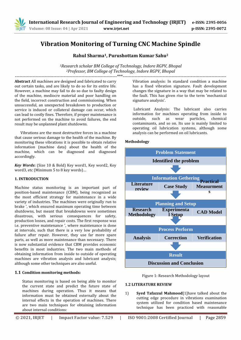
Methodology
Figure 1: Research Methodology layout
1.2 LITERATURE REVIEW
1) Syed Tafazzul Mahmood[1]have talked about the cutting edge procedure in vibrations examination system utilized for condition based maintenance technique has been practiced with reasonable
Result
Discussion and Conclusion
Process Perform
Analysis Correction Verification
Planning and Setup
Research Methodology
Experimental Setup
CAD Model
Information Gethering
Literature review
Case Study Practical
Measurments
Problem Statement
Identified the problem

International Research Journal of Engineering and Technology (IRJET) e-ISSN: 2395-0056
Volume: 08 Issue: 04 | Apr 2021 www.irjet.net p-ISSN: 2395-0072
© 2021, IRJET | Impact Factor value: 7.529 | ISO 9001:2008 Certified Journal | Page 2860
estimations on plant machine utilizing information obtaining equipment/programming and investigation done in Matlab. The general accessibility is enhancing by planning/upgrading the framework for higher unwavering quality and limits the requirement for support. Condition marks of a machine, has checked to watch and relate disintegration and issues are identified, the conceivable disappointment in the beginning stage. The normal result is found; enhance the dependability of fault identification and examination. The exploration venture still leaves a space for the 'Prognosis'part.
2) Andrew K.S. Jardine, Daming Lin and DraganBanjevic[2]have investigated a few books on information obtaining procedures utilized in condition checking, time space examination, recurrence area examination and time recurrence investigation. They additionally plate about the two basic boundaries in current industry. The two traditional support strategies, in particular the raced to-disappointment approach and the time sensitive preventive upkeep can be connected to some exceptional cases with attractive outcomes. In any case, by and large, particularly when both support and disappointment are all around exorbitant, CBM is completely a superior decision than the ordinary ones. Master information in both the application field and the unwavering quality and upkeep hypothesis is required for picking the best support approaches.
3) S. Saravanan, G.S. Yadava and P.V. Rao[3]have a
disk in their investigation, basic subsystems and segments have been recognized for machine utilizing disappointment information. The utilization of condition observing strategies like vibration, acoustic emanation (AE) and surface unpleasantness checking has been effectively executed for diagnosing defective direction in a machine. They have achieved the accompanying ends: Headstock subsystem is basic since it faces a more drawn out personal time and regular failure of parts like axle course and riggings. For imperfect bearing conditions, by and large, vibration levels at headstock shaft beatings are higher than those in deformity free machines. This expansion in vibration level is a lot more noteworthy at higher feed and profundity of cut qualities. For inadequate beating conditions, huge tops at the beating issue frequencies are watched. Bigger estimated sullying particles increment surface waviness impressively. Subsequently, the vibration level expanded extensively at bigger molecule sizes. AE levels demonstrate an expanding pattern with an expansion in feed rate and profundity of cut. For
damaged bearing conditions, AE levels are higher than those deliberate under solid conditions. The expansion in AE levels is a lot more prominent for higher estimations of feed and profundity of cut. For blemished bearing condition, surface harshness worth increments pointedly. It is seen from the FAAS think about that littler contaminant particles back the wear out of the bearing components.
1.3 VIBRATION MEASUREMENT
The idea of sound and vibrations to be estimated can change generally. Sound can be "uproarious" (thunder or murmur like), like that from an intensely dealt interstate, while vibrations of a machine are regularly commanded by the rotational recurrence and its products. A machine under steady stacking emits a stationary commotion, while the clamor at an air terminal will, in general, is discontinuous. In addition, the motivation behind estimations shifts. The usually observed vibration sign are removal, speed, and increasing speed.
1.4 SOFTWARE APPLICATION
The name MATLAB represents Matrix Laboratory. MATLAB was formed at first to give straightforward access to system programming made by the LINPACK (straight structure group) and EISPACK (Eigen structure pack) adventures.
MATLAB is a world-class language for particular preparing. It fuses the computation, recognition, and programming condition. In addition, MATLAB is a bleeding edge programming language condition: it has refined data structures, contains worked in changing and investigating mechanical assemblies, and supports object-masterminded programming. These variables make MATLAB an amazing instrument for instructing and research.
MATLAB has numerous favourable circumstances contrasted with ordinary codes (e.g., C, FORTRAN) for taking care of specialized issues. MATLAB is an intelligent framework whose fundamental information component is a cluster that does not require dimensioning. The product bundle has been economically accessible since 1984 and is presently considered as a standard apparatus at most colleges and businesses around the world.
2. Detection and Analysis
Analysis
With effective test setup and information securing, the vibration mark must be fathomable to acquire results. This should be possible by changing over time space information to recurrence area information utilizing 'Fast Fourier Transform'. This recurrence area range can be

International Research Journal of Engineering and Technology (IRJET) e-ISSN: 2395-0056
Volume: 08 Issue: 04 | Apr 2021 www.irjet.net p-ISSN: 2395-0072
© 2021, IRJET | Impact Factor value: 7.529 | ISO 9001:2008 Certified Journal | Page 2861
additionally used to distinguish, disengage and confirm early issues giving inside and out investigation and degree for anticipation utilizing underlying driver examination.
The two kinds of investigation generally utilized are drifting examination and cascade investigation. By breaking down the ceaseless patterns of the spectra the deficiencies can be distinguished in beginning periods and forming activity intends to redress them. The marks are gathered all the time with the goal that the slanting can be contrasted with comprehend the conduct of the machine. Drifting examination depends on 'narrowband' or 'broadband', while a graphical correlation of the general difference in the factory machine's full vibration mark and its discrete recurrence segments over a specific timeframe.
Figure 0.1: Time Domain Spectrum of collected data set
Alarm limits
After the data is acquired, setting the alarm limits poses quite a challenge. The reference level has to be decided and the boundary conditions for acceptable, moderate and extreme level must be set. The reference level is set considering the size of the machine, load during the operations and the history of the machine. In the present case fixed alarm limits are considered according to standards rather than reading the vibration and calculating alarm limit on instinct. The ISO standard utilized is 2372/10816 which gives the acknowledgment direction to the machines with velocities running 600-12000 rpm)[1]
Vibration velocity IPS (RMS)
Group 4 Integrated Driver
Group 3 External Driver
Group 2 Motors 160 < H < 315mm
Group 1 Motors H > 315mm
Rigid
Flexible
Rigid
Flexible
Rigid
Flexible
Rigid
Flexible
0.71
0.43
0.28
0.18
0.14
0.11
0.09
0.06
0.03
Table 0.1: ISO 10816 Charts[29]
Envelope Spectrum Analysis for Bearing Diagnosis
Power spectral density work (PSD) demonstrates the quality of the varieties in an element of recurrence. PSD is consolidated in the present examination to see at which frequencies varieties are solid and at which frequencies varieties are feeble. The unit of PSD is vitality per recurrence (width) and you can get vitality inside a particular recurrence run by coordinating PSD inside that recurrence go. Calculation of PSD is done in Matlab program for the present undertaking
The PSD matlab program developed for the current case: [32]
Visualize the raw inner race fault data in the time domain.
xOuter = bearing.sr;
tOuter = (0:length(xOuter)-1)/fsOuter;
figure
plot(tOuter, xOuter)
xlabel('Time, (s)')
ylabel('Acceleration (g)')
title('Raw Signal: Outer Race Fault')
xlim([0 0.1])

International Research Journal of Engineering and Technology (IRJET) e-ISSN: 2395-0056
Volume: 08 Issue: 04 | Apr 2021 www.irjet.net p-ISSN: 2395-0072
© 2021, IRJET | Impact Factor value: 7.529 | ISO 9001:2008 Certified Journal | Page 2862
Figure 0.2: Time Domain Spectrum of collected data set
Visualize the raw data in frequency domain.
figure
[pOuter, fpOuter] = pspectrum(xOuter, fsOuter);
pOuter = 10*log10(pOuter);
plot(fpOuter, pOuter)
xlabel('Frequency (Hz)')
ylabel('Power Spectrum (dB)')
title('Raw Signal: Outer Race Fault')
legend('Power Spectrum')
Figure 0.3: Frequency Domain Spectrum of collected data set
Now zoom in the power spectrum of the raw signal in low frequency range to take a closer look at the frequency response at BPFO and its first several harmonics.
figure
plot(fpOuter, pOuter)
ncomb = 10;
helperPlotCombs(ncomb, 82)
xlabel('Frequency (Hz)')
ylabel('Power Spectrum (dB)')
title('Raw Signal: Outer Race Fault')
legend('Power Spectrum', 'BPFO Harmonics')
xlim([0 1000])
Figure 0.4: Magnified view of Frequency Domain Spectrum
No unmistakable example is obvious at BPFO and its music. Frequency examination of the crude sign does not give helpful indicative data.
Taking a gander at the time-area information, it is seen that the sufficiency of the crude sign is regulated at a specific recurrence. It is realized that the recurrence the moving component hitting a neighborhood deficiency at the inward race, that is BPFO, is 82 Hz. This demonstrates the bearing possibly has an external race deficiency.
figure
subplot(2, 1, 1)
plot(tOuter, xOuter)
xlim([0.04 0.06])

International Research Journal of Engineering and Technology (IRJET) e-ISSN: 2395-0056
Volume: 08 Issue: 04 | Apr 2021 www.irjet.net p-ISSN: 2395-0072
© 2021, IRJET | Impact Factor value: 7.529 | ISO 9001:2008 Certified Journal | Page 2863
title('Raw Signal: Outer Race Fault')
ylabel('Acceleration (g)')
annotation('doublearrow', [0.37 0.71], [0.8 0.8])
text(0.047, 20, ['0.009 sec \approx 1/BPFO, BPFO = ' num2str(82)])
To extract the modulated amplitude, compute the envelope of the raw signal, and visualize it on the bottom subplot.
subplot(2, 1, 2)
[pEnvOuter, fEnvOuter, xEnvOuter, tEnvOuter] = envspectrum(xOuter, fsOuter);
plot(tEnvOuter, xEnvOuter)
xlim([0.04 0.06])
xlabel('Time (s)')
ylabel('Acceleration (g)')
title('Envelope signal')
Figure 0.5: Raw Signal and Envelope Signal of collected data
Now compute the power spectrum of the envelope signal and take a look at the frequency response at BPFO and its harmonics.
figure
plot(fEnvOuter, pEnvOuter)
xlim([0 1000])
ncomb = 10;
helperPlotCombs(ncomb, 82)
xlabel('Frequency (Hz)')
ylabel('Peak Amplitude')
title('Envelope Spectrum: Outer Race Fault')
legend('Envelope Spectrum', 'BPFO Harmonics')
Figure 0.6: Envelope Spectrum of BPFO Harmonics
It is shown that most of the energy is focused at BPFO and its harmonics. That indicates an outer race fault of the bearing, which matches the fault type of the data.
3. CONCLUSION
In this exploration work fault detection techniques for moving component orientation were utilized. A detailed investigation of the frequency domain methods was carried out under bearing fault conditions. The trial results demonstrate that restricted data can be found from the time-domain however the data can be gotten by changing over the time-domain to frequency domain by FFT investigation. Vibration estimation in the frequency domain has the preferred position that it can recognize the location of fault. The immediate vibration range from an inadequate bearing may not demonstrate the imperfection at the underlying stage. Be that as it may, envelope examination is a progressively successful dependable way to deal with catching the shortcoming highlights as it depends on high-frequency signals where the noise and interference sources are smothered altogether. The inner

International Research Journal of Engineering and Technology (IRJET) e-ISSN: 2395-0056
Volume: 08 Issue: 04 | Apr 2021 www.irjet.net p-ISSN: 2395-0072
© 2021, IRJET | Impact Factor value: 7.529 | ISO 9001:2008 Certified Journal | Page 2864
race deficiency display itself with a consonant range at its element frequency. So accomplishes for the outrace deficiency. In addition, once the fault type is defined, the severity of it also assessed based on the amplitude of envelop spectrum. When ball rotates at enter and exit of load zone, the bearing vibration adequacy was seen to be higher and contrasted with ball at meet point of load zone. It demonstrates that there was a difference in the amplitude of vibration as it goes higher in the regular interval of time with respect to position of defect on inner race. Further the FMEA is done for the equivalent and it is discovered that the real purpose behind the internal race issue was rolling contact fatigue. It was seen from the examination that because of the negative temperature edge between the working temperature of the bearing and constraining temperature of the oil which is estimated at the 75°C on the external race and increasingly inside the bearing internal race, the freedom class is moved towards the preload zone. Surface distress is damage initiated at the rolling contact surfaces due to plastic deformation of the surface asperities. Contact between the asperities of the rolling element and bearing raceway is most often the result of inadequate lubrication conditions (insufficient lubricant film thickness). This contact may be caused by insufficient lubrication flow/availability, improper lubricant for the application, operating temperatures beyond the expected level or rough surface finishes. Contact and plastic deformation of the surface asperities can lead to sliding motion under low lubricant film conditions can significantly accelerate the surface damage. The bearing subsurface begins spalling out in the inner race that is the reason the unexpected breakdown happens in the bearing. After the last dialog of this point it is distinguished that bearing must be work inside an incentive inside the freedom class to expand the unwavering quality of the bearing, the primary bearing was chosen with
REFERENCES
[1] S. T. Mahmood, “Use of Vibrations Analysis Technique in Condition Based Maintenance,” Royal Institute of Technology, Stockholm, Sweden, 2012.
[2] A. K. S. Jardine, D. Lin, and D. Banjevic, “A review on machinery diagnostics and prognostics implementing condition-based maintenance,” Mech. Syst. Signal Process., vol. 20, no. 7, pp. 1483–1510, 2006.
[3] S. Saravanan, G. S. Yadava, and P. V. Rao, “Condition monitoring studies on spindle bearing of a lathe,” Int. J. Adv. Manuf. Technol., vol. 28, no. 9–10, pp. 993–1005, Jul. 2006.
[4] A. Rastegari, A. Archenti, and M. Mobin, “Condition based maintenance of machine tools: Vibration monitoring of spindle units,” Proc. - Annu. Reliab.
Maintainab. Symp., 2017.
[5] T. Seecharan, A. Labib, and A. Jardine, “Maintenance strategies: Decision Making Grid vs Jack-Knife Diagram,” J. Qual. Maint. Eng., vol. 24, no. 1, pp. 61–78, Mar. 2018.
[6] Martin and K F, “0890-6955(94)E0015--B a Review By Discussion of Condition Monitoring and Fault Diagnosis in Machine Tools,” Int. J. Mach. Tools Manufact, vol. 34, no. 4, pp. 527–551, 1994.
[7] A. Anand and H. Roy, “Static and Dynamic Analysis of Lathe Spindle using ANSYS,” vol. 13, no. 9, pp. 6994–7000, 2018.
[8] S. Devendiran and K. Manivannan, “Vibration based condition monitoring and fault diagnosis technologies for bearing and gear components-A review,” Int. J. Appl. Eng. Res., vol. 11, no. 6, pp. 3966–3975, 2016.
[9] G. W. Vogl and M. A. Donmez, “A defect-driven diagnostic method for machine tool spindles,” CIRP Ann. - Manuf. Technol., vol. 64, no. 1, pp. 377–380, 2015.
[10] H. Wang and P. Chen, “Fault diagnosis method based on kurtosis wave and information divergence for rolling element bearings,” WSEAS Trans. Syst., vol. 8, no. 10, pp. 1155–1165, 2009.
[11] J. Chebil, M. Hrairi, and N. Abushikhah, “Signal Analysis of Vibration Measurements for Condition Monitoring of Bearings,” Aust. J. basic Appl. Sci., vol. 5, no. 1, pp. 70–78, 2011.
[12] C. K. Riessman, “BEARING FAULT DIAGNOSIS BASED ON VIBRATION SIGNALS,” J. Librariansh. Inf. Sci., vol. 41, no. 1, pp. 19–28, 2009.
[13] H. Saruhan, S. Saridemir, A. Çiçek, and I. Uygur, “Vibration analysis of rolling element bearings defects,” J. Appl. Res. Technol., vol. 12, no. 3, pp. 384–395, 2014.
[14] S. Shivakumar, A. N. Kallol, and V. Khadakbhavi, “Analysis of Lathe Spindle Using Ansys,” Int. J. Sci. Eng. Res., vol. 4, no. 9, pp. 431–440, 2013.
[15] M. S. Jagadish and H. V Ravindra, “Monitoring The Machine Elements In Lathe Using Vibration Signals,” 2003.
[16] A. Rastegari, Asset Intelligence through Integration and Interoperability and Contemporary Vibration Engineering Technologies. Springer International Publishing, 2019.