Embed Size (px)
Citation preview

■Floor plan (Gantry loader type)
IN-LINE OPPOSED TWIN SPINDLE CNC TURNING MACHINE
CAT. NO. 22T0892 I 10-09-1(X-TU)
2, Nakajima, Hashizume, Inuyama-shi, AICHI 484-8502, JAPANTEL : +81-(0)568-61-3645 FAX : +81-(0)568-61-6455Headquarters136, Takeda-Mukaishiro-cho, Fushimi-ku, KYOTO 612-8686, JAPANTEL : +81-(0)75-672-8138 FAX : +81-(0)75-672-8691
International Business Dept.
http://www.muratec.co.jpe-mail [email protected]
MACHINE TOOLS DIVISIONMURATA MACHINERY USA, INC2120 Queen City Drive, P.O.Box 667609, Charlotte, N.C. 28208, U.S.A.TEL : +1-704-875-9280 FAX :+1-704-392-6541http://www.muratec-usa.com
MURATA MACHINERY EUROPE GmbHHanns-Martin-Schleyer-Straße 3, D-47877, Willich, GERMANYTEL : +49-(0)2154-914-250 FAX : +49-(0)2154-914-283
MURATA DO BRASIL COMERCIO E REPRESENTACAO DE MAQUINAS LTDA.Estrada de Santa lzabel, 3383-KM 38,5 Itaquaquecetuba-SP-CEP 08599-000 BRAZILTEL : +55-(0)11-4648-6222 FAX : +55-(0)11-4648-6737
MURATA MACHINERY (SHANGHAI) CO.,LTD[Registry Add]135 Fu Te Xi Yi Rd., Wai Gao Qiao Free Trade Zone, Pudong, Shanghai, CHINA[Contact Add]150 Xin Gao Rd., Qingpu Industrial Zone, Shanghai, 201700, CHINATEL:+86-(0)21-6921-2300 FAX:+86-(0)21-6921-2330
■MT12
■MT25
(unit : mm)
(unit : mm)
External paint color Standard : Light Gray / Gray Blue
Other colors available on special order.
■MT20 (unit : mm)(Safty fence height)
(Loader at highest position)
Work feeder WF14L-160II with safety cover
Chip conveyor discharge height : 1100
(Spindle center height)
(Spindle center)
2700
790 940
1465
15
2110 (stroke)
920
270
1010
1260 1440 100
1020
4001105
750
170
2500
257 550
1875
38
360
688
1850
3790
1100
2750
170
)2708
(
Coolant pumpHydraulic unit
Lubrication unit
Pneumatic panel
Power supply
Operation panel
Control panel
Front Plane
(Spindle center)
Work feeder WF14L-160II with safety cover
(Safety fence height)
(Loader at highest position)
Lubrication unit
Swing Operation panel
(Spindle center height)
Pneumatic panel
Chip conveyor discharge height : 960
Hydraulic unit (L)
Coolant pump
Hydraulic unit (R)
92
450
2200
4060(stroke)
2980 865
2250400(stroke)
560
1640
5401240550 350
830
270
2100
4152
215
1100
3042
3200
2250
763
665
778
650
764.6 620 700 620
500
205
1900
2490
3600
(Safety fence height)
(Loader at highest position)
587
1250
2830 (stroke)420
3700
12201190
200
Hydraulicunit (L)
Chip conveyor discharge height : 1000
Chip conveyor discharge height : 1200
C/L
Lubrication unit
Hydraulic unit (R)
Coolant pump
Power supply
Pneumatic panel
400 mm slideOperation panel
Swing
Spindle
face (R)
Spindle
face (L)
Control panel
Front Plane
Front Plane
IN-LINE OPPOSED TWIN SPINDLE CNC TURNING MACHINEIN-LINE OPPOSED TWIN SPINDLE CNC TURNING MACHINE1 2
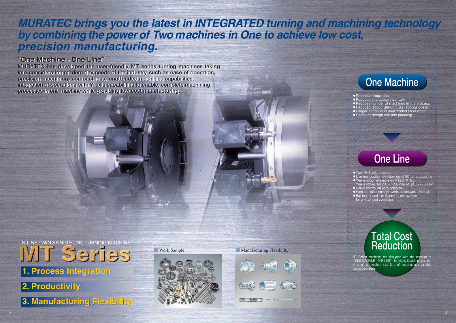
MT Series machines are designed with the concept of “ONE MACHINE - ONE LINE” for highly flexible production of small or medium size lots of continuously variable production needs.
One Machine
One Line
Total Cost Reduction
●Process Integration ●Reduced in-process inventory ●Reduced number of machines in the process ●Reduced labour, Set-up, Jigs, Tooling costs ●Longer continuous unattended production ●Compact design and line planning
●Two 15-Station turrets ● Live tool position available on all 30 turret stations ●Y-axis option available on MT20, MT25 Y-axis stroke MT20 : + / - 50 mm, MT25 : + / - 60 mm ●C-axis control on both spindles ●High precision spindle synchronous work transfer ●Bar feeder and / or Gantry loader system for unattended operation
■Manufacturing Flexibility■Work Sample
IN-LINE TWIN SPINDLE CNC TURNING MACHINE
“One Machine - One Line”MURATEC has developed the user-friendly MT series turning machines takinginto consideration modern day needs of the industry such as ease of operation,precision machining, compactness, unattended machining capabilities,integration of operations with Y-axis capabilities to enable, complete machiningprocesses in one machine while providing low cost manufacturing.
MURATEC brings you the latest in INTEGRATED turning and machining technologyby combining the power of Two machines in One to achieve low cost,precision manufacturing.“One Machine - One Line”MURATEC has developed the user-friendly MT series turning machines takinginto consideration modern day needs of the industry such as ease of operation,precision machining, compactness, unattended machining capabilities,integration of operations with Y-axis capabilities to enable, complete machiningprocesses in one machine while providing low cost manufacturing.

IN-LINE OPPOSED TWIN SPINDLE CNC TURNING MACHINEIN-LINE OPPOSED TWIN SPINDLE CNC TURNING MACHINE
1st operation chamfer
1st operation drilling2nd operation chamfer
43
Process Integration,High Productivity
Face live tool head Cross live tool head
Helical tapping
(X-axis + Y-axis + Z-axis)
Polar co-ordinate interpolation function
Cylindrical interpolation function
Off-center threading Cam interpolation machining
Cam interpolation machining on front face Multi-face cutting operation
Completely integrated turning and machiningfrom all directions in one machine set-up
Largest number of turret stations(30 total tools available)
The versatility of applications for complete machining in one set-up is greatlyenhanced. Larger number of available tools eliminates tool changeover timeand also facilitates longer unattended operations resulting in maximizedproductivity. Live tooling heads (option) can be mounted on any and all of theturret stations. VDI tooling is used as a standard (MT20, MT25) for quick toolchangeover.
Spindle synchronous rotation for accuratetransfer of the workpiece from theleft spindle to the right spindle
Workpiece transfer from one spindle to the other is done with the synchronisedrotation of both spindles. Accurate orientation is achieved using the C-axiscontrol. The result is precision relational positioning of operations performedat both the spindles. This system does not require any jigs for phaseadjustments, thus reduces cost and operation time.
Live tool capability increases versatility ofapplications (Option)Live tool option on all 30-turret stationsLive tool heads can be mounted on any and all of the 30 turret stations. Thisallows for complete integrated machining including drilling, milling andtapping in one set-up for a wide variety of components.
SpecificationsMT12 MT20 MT25
Live tool motor 3 kW (9 Nm/Continuous) 3 kW (12 Nm/Continuous) 4 kW (22 Nm/Continuous)Max. live tool speed 4000 rpm 3600 rpm 3000 rpm
Tool size Milling φ 16 mm φ20 mm φ20 mm Tapping M12 M16 M16
Rigid tap functionRigid tap function is available with the live tool option. Rigid tap functionprovides high speed, accurate tapping operations while eliminating the needfor special tap holders.
Process integration using Y-axis on both turrets[MT20, MT25] and C-axis on both spindles (Option)
Y-axis option is available on both spindles (MT20, MT25). Operations suchas off-center drilling, face milling, key way milling, helical tapping arepossible with high relative positioning accuracy. This feature greatly increasesthe versatility of applications within the MT machines.
SpecificationsMT12 MT20 MT25
Y-axis stroke ― ± 50 mm ±60 mmC-axis positioning accuracy ± 0.001° ± 0.001° ± 0.015°Maximum C-axis speed 200 rpm 100 rpm 100 rpm
Y-axis live tool capabilities for helical tapping
Cylindrical interpolation
(C-axis + Z-axis)
Polar interpolation
(C-axis + X-axis) (C-axis + X-axis)
2nd operation groove milling relative to cross drilling
1st operation cross drilling
Facelive tool head
Angularlive tool head
Crosslive tool head
Offset crosslive tool head
Angularlive tool head
Crosslive tool head
Turninghead
Knurling toolhead
Knee toolhead
+
+ +
+
Machine : MT20 Example : Carbon steel, φ 100 mm×L 100 mm
2nd Operation1st Operation
O. D. Turning O. D. Grooving I.D. Boring Plain Milling Rigid Tapping
Loading
Unloading
Plain Milling O. D. Turning Rigid Tapping Through Drilling I.D. Boring
Key-way Milling
Kissing
Kissing
Cycle Time 144 sec.
6-Plain machining using Y-axis, C-axis capabilities
IN-LINE OPPOSED TWIN SPINDLE CNC TURNING MACHINEIN-LINE OPPOSED TWIN SPINDLE CNC TURNING MACHINE5 6
High Speed, High Accuracyand High Rigidity
Left spindle Right spindle (moving axis)
Positioning & torque check
Three piece couplingAir purge
Double-row angular contact ball bearing
Cylindrical double roller bearing
Spindle air purge
Highly accurate repeatabilityon complicated workpieces
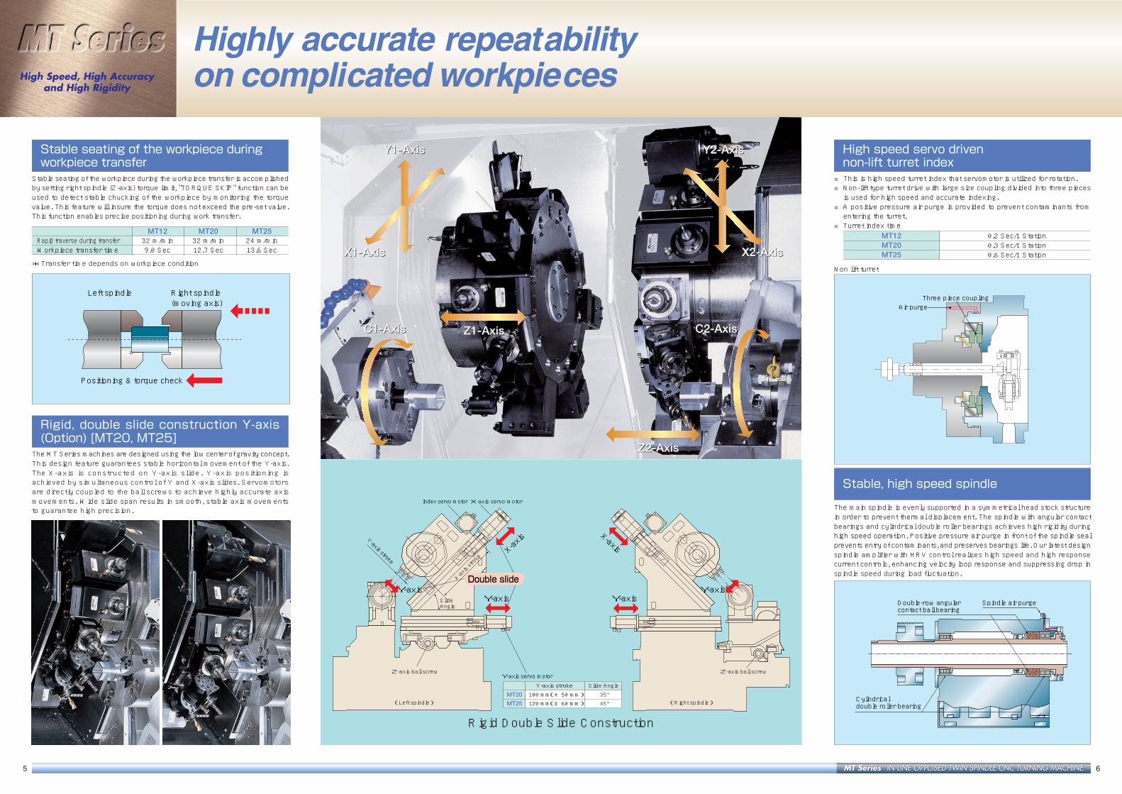
Stable seating of the workpiece duringworkpiece transfer
Stable seating of the workpiece during the workpiece transfer is accomplishedby setting right spindle (Z-axis) torque limit, "TORQUE SKIP" function can beused to detect stable chucking of the workpiece by monitoring the torquevalue. This feature will insure the torque does not exceed the pre-set value.This function enables precise positioning during work transfer.
MT12 MT20 MT25Rapid traverse during transfer 32 m/min 32 m/min 24 m/minWorkpiece transfer time 9.0 Sec 12.7 Sec 13.6 Sec
*Transfer time depends on workpiece condition
Rigid, double slide construction Y-axis(Option) [MT20, MT25]
The MT Series machines are designed using the low center of gravity concept.This design feature guarantees stable horizontal movement of the Y-axis.The X-axis is constructed on Y-axis s l ide. Y-axis posit ioning isachieved by simultaneous control of Y and X-axis slides. Servomotorsare directly coupled to the ball screws to achieve highly accurate axismovements. Wide slide span results in smooth, stable axis movementsto guarantee high precision.
High speed servo drivennon-lift turret index
■This is high speed turret index that servomotor is utilized for rotation.■Non-lift type turret drive with large size coupling divided into three piecesis used for high speed and accurate indexing.
■A positive pressure air purge is provided to prevent contaminants fromentering the turret.
■ Turret index timeMT12 0.2 Sec/1 StationMT20 0.3 Sec/1 StationMT25 0.6 Sec/1 Station
Stable, high speed spindle
The main spindle is evenly supported in a symmetrical head stock structurein order to prevent thermal displacement. The spindle with angular contactbearings and cylindrical double roller bearings achieves high rigidity duringhigh speed operation. Positive pressure air purge in front of the spindle sealprevents entry of contaminants, and preserves bearings life. Our latest designspindle amplifier with HRV control realises high speed and high responsecurrent controls, enhancing velocity loop response and suppressing drop inspindle speed during load fluctuation.
Index servo motor X-axis servo motor
X-axis stroke
Y-axis servo motor
Y-axis Y-axisY-axis Y-axis
X-axis X-axis
Z-axis ball screw Z-axis ball screw
(Right spindle) (Left spindle)
Y-axis stroke
Slide Angle
Double slide
Y-axis stroke Slide Angle MT20 100 mm(±50 mm) 35° MT25 120 mm(±60 mm) 45°
Z1-AxisC1-Axis
Y1-Axis
X1-Axis
Z2-Axis
C2-Axis
Y2-Axis
X2-Axis
Z1-AxisC1-Axis
Y1-Axis
X1-Axis
Z2-Axis
C2-Axis
Y2-Axis
X2-AxisNon lift turret
Rigid Double Slide Construction
IN-LINE OPPOSED TWIN SPINDLE CNC TURNING MACHINEIN-LINE OPPOSED TWIN SPINDLE CNC TURNING MACHINE
Easy coolant tank maintenance
The coolant sump is on casters and separate from the chip conveyor. Thecoolant sump simply rolls out from under the front of the machine. This easescleaning work and reduces cleaning time. Portable chip box in the coolantsump holds stray chips.
7 8
Easy Maintenance &Safety Construction
Flexible movement of operation panel
Operation panel can swing at 90° and can be set at convenient positions toset up left and right spindles and turrets.
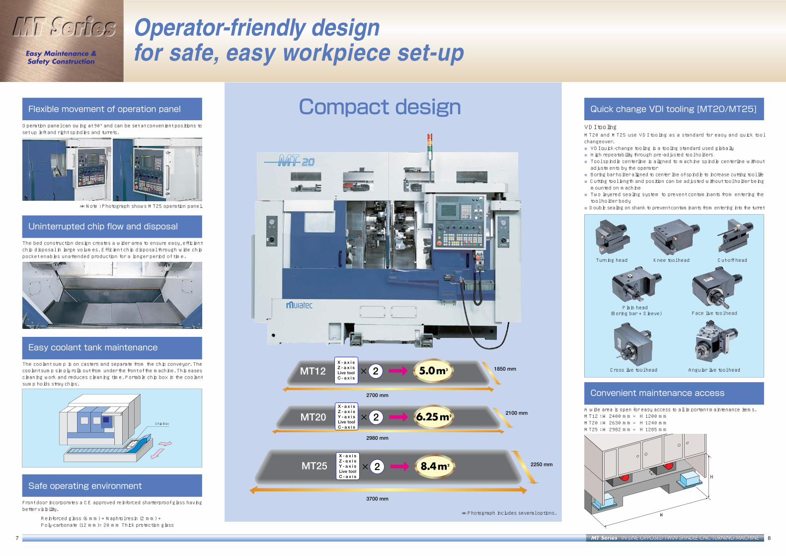
Compact design
Chip Box
Uninterrupted chip flow and disposal
The bed construction design creates a wider area to ensure easy, efficientchip disposal in large volumes. Efficient chip disposal through wide chippocket enables unattended production for a longer period of time.
Operator-friendly designfor safe, easy workpiece set-up
Convenient maintenance access
A wide area is open for easy access to all important maintenance items.MT12 : W 2400 mm × H 1200 mmMT20 : W 2630 mm × H 1240 mmMT25 : W 2982 mm × H 1285 mm
*Photograph includes several options.
H
W
X - a x i s Z - a x i s Y - a x i s Live tool C - a x i s
8.4m2× 2
3700 mm
2250 mm
X - a x i s Z - a x i s Live tool C - a x i s
5.0m2× 2
2700 mm
1850 mm
X - a x i s Z - a x i s Y - a x i s Live tool C - a x i s
6.25m2× 2
2980 mm
2100 mmMT20
MT12
MT25
Quick change VDI tooling [MT20/MT25]
VDI toolingMT20 and MT25 use VDI tooling as a standard for easy and quick toolchangeover.■VDI quick-change tooling is a tooling standard used globally■High repeatability through pre-adjusted tool holders■Tool spindle centerline is aligned to machine spindle centerline withoutadjustments by the operator
■Boring bar holder aligned to center line of spindle to increase cutting tool life■Cutting tool length and position can be adjusted without tool holder beingmounted on machine
■Two layered sealing system to prevent contaminants from entering thetool holder body
■Double sealing on shank to prevent contaminants from entering into the turret
Knee tool head
Plain head (Boring bar + Sleeve)
Cross live tool head
Turning head Cut-off head
Face live tool head
Safe operating environment
Front door incorporates a CE approved reinforced shatterproof glass havingbetter visibility.
Reinforced glass (6 mm) + Naphtol resin (2 mm) +Poly-carbonate (12 mm)= 20 mm Thick protection glass
Angular live tool head
* Note : Photograph shows MT25 operation panel.
IN-LINE OPPOSED TWIN SPINDLE CNC TURNING MACHINEIN-LINE OPPOSED TWIN SPINDLE CNC TURNING MACHINE
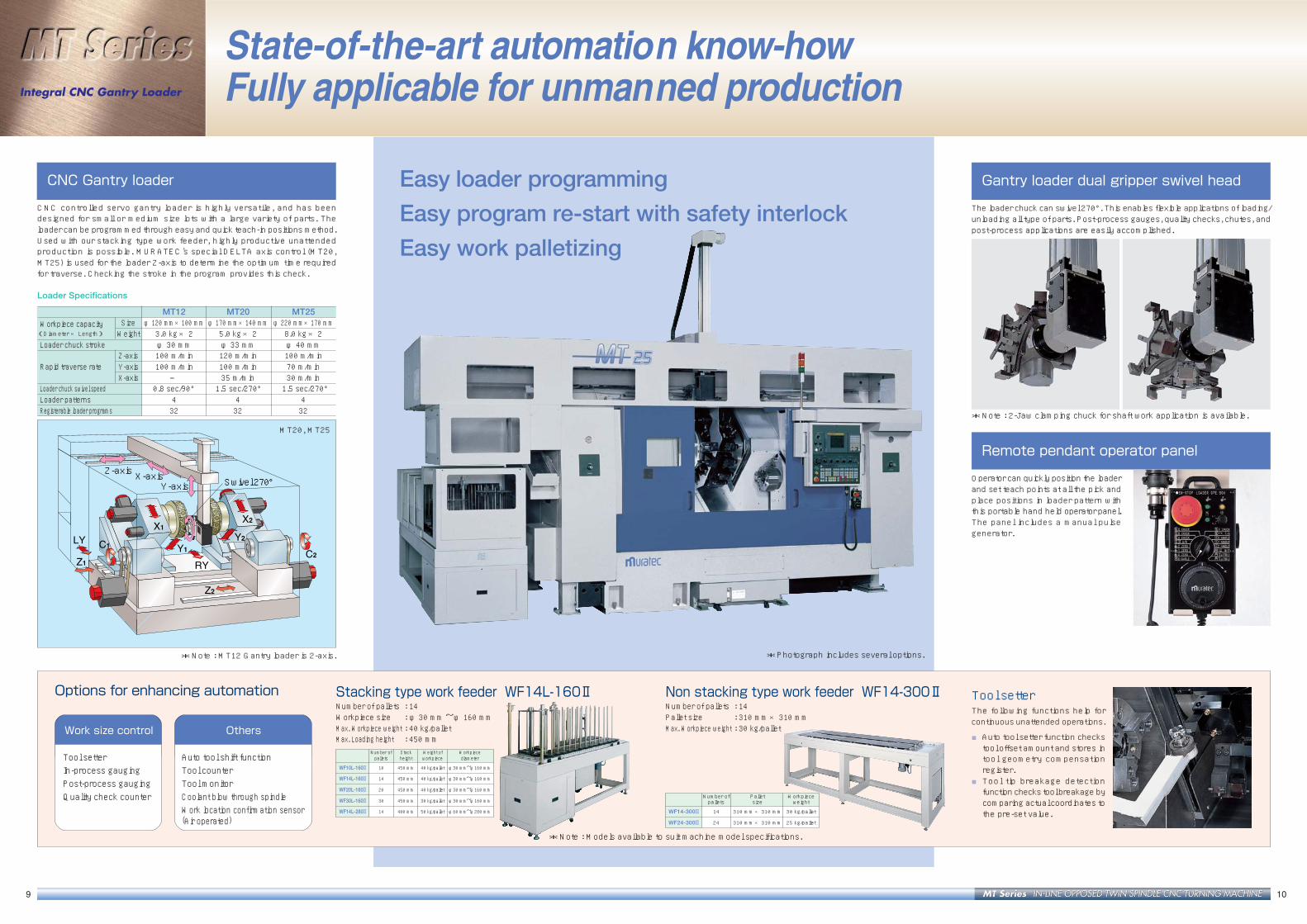
Gantry loader dual gripper swivel head
The loader chuck can swivel 270°. This enables flexible applications of loading/unloading all type of parts. Post-process gauges, quality checks, chutes, andpost-process applications are easily accomplished.
9 10
CNC Gantry loader
CNC controlled servo gantry loader is highly versatile, and has beendesigned for small or medium size lots with a large variety of parts. Theloader can be programmed through easy and quick teach-in positions method.Used with our stacking type work feeder, highly productive unattendedproduction is possible. MURATEC's special DELTA axis control (MT20,MT25) is used for the loader Z-axis to determine the optimum time requiredfor traverse. Checking the stroke in the program provides this check.
Loader Specifications
MT12 MT20 MT25Workpiece capacity Size φ 120 mm × 100 mm φ170 mm × 140 mm φ220 mm × 170 mm(Diameter × Length) Weight 3.0 kg× 2 5.0 kg× 2 8.0 kg× 2Loader chuck stroke φ 30 mm φ33 mm φ 40 mm
Z-axis 100 m/min 120 m/min 100 m/minRapid traverse rate Y-axis 100 m/min 100 m/min 70 m/min
X-axis ― 35 m/min 30 m/minLoader chuck swivel speed 0.8 sec/90° 1.5 sec/270° 1.5 sec/270°Loader patterns 4 4 4Registerable loader programs 32 32 32
Integral CNC Gantry Loader
Options for enhancing automation Tool setterThe following functions help forcontinuous unattended operations.
■Auto tool setter function checkstool offset amount and stores intool geometry compensationregister.
■ Tool tip breakage detectionfunction checks tool breakage bycomparing actual coordinates tothe pre-set value.
Remote pendant operator panel
Operator can quickly position the loaderand set teach points at all the pick andplace positions in loader pattern withthis portable hand held operator panel.The panel includes a manual pulsegenerator.
State-of-the-art automation know-howFully applicable for unmanned production
Work size control
Tool setterIn-process gaugingPost-process gaugingQuality check counter
Others
Auto tool shift functionTool counterTool monitorCoolant blow through spindleWork location confirmation sensor(Air operated)
*Photograph includes several options.
Stacking type work feeder WF14L-160ⅡNumber of pallets : 14Workpiece size : φ 30 mm ~φ 160 mmMax. Workpiece weight : 40 kg/palletMax. Loading height : 450 mm
Number of Stack Weight of Workpiecepallets height workpiece diameter
WF10L-160II 10 450 mm 40 kg/pallet φ30 mm~φ160 mm
WF14L-160II 14 450 mm 40 kg/pallet φ30 mm~φ160 mm
WF20L-160II 20 450 mm 40 kg/pallet φ30 mm~φ160 mm
WF30L-160II 30 450 mm 30 kg/pallet φ30 mm~φ160 mm
WF14L-280II 14 400 mm 50 kg/pallet φ60 mm~φ280 mm
Non stacking type work feeder WF14-300ⅡNumber of pallets : 14Pallet size : 310 mm×310 mmMax. Workpiece weight : 30 kg/pallet
Number of Pallet Workpiecepallets size weight
WF14-300II 14 310 mm×310 mm 30 kg/pallet
WF24-300II 24 310 mm×310 mm 25 kg/pallet
Swivel 270° Y-axis
Z-axis X-axis
*Note : MT12 Gantry loader is 2-axis.
MT20, MT25
Easy loader programming
Easy program re-start with safety interlock
Easy work palletizing
*Note : 2-Jaw clamping chuck for shaft work application is available.
*Note : Models available to suit machine model specifications.

IN-LINE OPPOSED TWIN SPINDLE CNC TURNING MACHINEIN-LINE OPPOSED TWIN SPINDLE CNC TURNING MACHINE 1211
Flexible Bar Work Processing
System configuration to suit customer needs
MURATEC's long experience in designing compact cells to full fledgedautomation systems, FMS, is used to design customer needs based systemlayout. A wide variety of system configuration is possible to create efficientsystem cells for various customer needs of small and variable parts lot,medium size lots and mass production system requirements.
Bar work automation
MT Series turning machines are designed for high speed, precision,unattended bar work. This is accomplished by interfacing an automatic barfeeder unit to the left spindle. A parts catcher with conveyance systems or agantry loader may be used for unloading and transferring of the workpieces.
Maximum bar size capacityMT12 MT20 MT25
Standard φ51 mm φ65 mm φ65 mmOption ― ― φ71 mm (Only Left)
A wide variety ofSystem Configuration
Hand Type Parts Catcher (Option)
Unload Conveyor (Option)
Left spindleRight spindle Rapid traverse (Return)
Torque check
Parts catcher (option)
An optional hand type parts catcher is used to grip the finished workpieceand insure proper discharge of the finished workpiece into a tray or aconveyor.
Maximum workpiece capacity (Diameter × Length)MT12 φ51 mm × 150 mm , Weight 2.5 kgMT20 φ65 mm × 160 mm , Weight 4.0 kgMT25 φ70 mm × 200 mm , Weight 6.5 kg
Bar-work and chuck-work flexibilityAll-in-one with flexible automation
Simultaneous check of cut-off operation
This function checks propercompletion of cut-offoperation by measuringtorque value, to initiateright spindle (Z-axis) returntraverse .
MT12 MT20 MT25
Right spindle (Forward movement)
Right spindle (Backward movement)
Hand close, chuck jaws open
Work Feeder → Turnaround Operation → Work Feeder1
Work Feeder → Both Spindle Same Operation → Work Feeder2
Work Feeder → Turnaround Operation → Parts Catcher3
Bar Feeder → Turnaround Operation → Work Feeder5
Bar Feeder → Turnaround Operation → Parts Catcher4������������
� �
�����������
���� �� ���� ������
���� ���� �
� � ���� ���� �
����� ��������
� �
����� ��������
���� ���� ������������
����� ��������
��� ��� ��� ���� ������������
�����������
���� �� ���� ������
� �� �
����� ��������
� ���� ��� ��� ���� ������� ������ ���
� ������������
���� ������ ���� �����
�������� �������� �����
��� �����������������
�� ���������
��� ���������
�����������
��� ��������� ���� ����� ����

IN-LINE OPPOSED TWIN SPINDLE CNC TURNING MACHINEIN-LINE OPPOSED TWIN SPINDLE CNC TURNING MACHINE
Abnormal load detection
MT Series turning machines uses abnormal load detection to detectabnormal load on all turret and loader axes. Any crash due to operator'smistake, programming mistake etc. will minimize severity of damage tothe machine by retracting the axis.
Control system & software
3-Stage tool monitor (option)MT Series incorporates 3-stage tool monitor functionto check abnormal load, warning load and low levelcutting loads. This function helps to detect tool/ drillbreakage during the cutting process.
Machine guideThis function helps to check machine status andguides the operator to restore machine statusfor automatic operations or machine zero set.
Diagnostics functionA display alarm will be accompanied by an explanation.A history of the last 200 alarms is maintained andcan be accessed on the display.
1413
Soft tool counterTool life management is possible by pre-setting dataat the tool counter function.
Soft work counterTotal counter and settable work counter are providedas a standard feature.
Auto tool shift function (option)Spare or redundant tools can be activated by toolcount or tool breakage detection.This tool monitor option is useful for continuous andunattended type operations.
Advanced user-friendly functions and displays
User-friendly operation panel
Operation panel buttons are clearly marked and logically groupedunder left spindle, right spindle and loader. Distinction is also made formanual and automatic operation. Symbolic button labels are used forinternational standards.
Left spindle(Manual)
Right spindle(Manual)
Left spindle(Automatic)
Right spindle(Automatic)
Loader(Automatic)
Simple timer screenEach timer can be set by 0.01 seconds on the timerscreens.Each individual timer name provides smoothsearching.
User-friendly loader teaching screenMuratec's unique teaching function and its screenfacilitate gantry loader position setting.Using both the teaching screen and the program screenare effective in reduction of tool changeover time.

IN-LINE OPPOSED TWIN SPINDLE CNC TURNING MACHINEIN-LINE OPPOSED TWIN SPINDLE CNC TURNING MACHINE 1615
■Tooling system
OD tool □25×150
Turning head
Knee tool head
φ40 Boring bar
Boring bar underφ40
Drill
Drill
Drill holder
Drill socket
or
Plain head (φ40)
15-station turret
Face live tool head
Cross live tool head
Offset cross live tool head
Angular live tool head
Reamer
End mill
Drill
Tap
Cut-off headCut-off tool
Sleeve Bush
Live tool collet φ3 ~ φ20
ID: φ8 φ10 φ12 φ16 φ20 φ25
ID: φ16 φ20 φ25 φ32
ID: φ16 φ20 φ25 φ32
MT1 MT2 MT3 MT4
OD tool□20×125
Turning head
Knee tool
Double-bore head(φ32・φ25)
φ25,φ32Boring bar
Boring bar underφ25
Boring bar underφ32
φ40Boring bar
Boring bar underφ40
Drill
Drill
Drill
Drill
Sleeve Bush
Drill holder
Drill socket
or
Drill holder
Drill socket
or
or
Plain head (φ40)
15-station turret
Face live tool head
Offset cross live tool head
Cross live tool headLive tool colletφ3~φ16
Reamer
End mill
Drill
Tap
Cut-off headCut-off tool
Sleeve Bush
Sleeve Bush
ID: φ8 φ10 φ12
ID: φ16 φ20
ID: φ8 φ10 φ12 φ16
ID: φ16 φ20 φ25
ID: φ8 φ10 φ12 φ16
ID: φ16 φ20 φ25 φ32
ID: φ16 φ20 φ25
MT1 MT2 MT3
ID: φ16 φ20 φ25 φ32
MT1 MT2 MT3 MT4
φ25
φ197
φ40φ32
45
9401020
81
95
95
X1 S
troke
200
X2 S
troke
200
155
200 Z2 Cutting Stroke
Max.110
650 Z2-axis Stroke95 100
Max.110 80
Z1 Stroke 200 190INDEX CLEARANCE R335
0.00φ46
φ165φ215129.2
1
8080 65
15
14
18.5
4581
1515 707015 15
3595
95 250
15
80
129.2155215
φ215φ165
15
110
95 130
50
14
204
110
185
310
310
60
440
SPIN
DLE
NOSE
940
SPIN
DLE
NOSE
0.00
195
Turret center 470 × 1 Max out Turret center 470 × 2 Max out
310
(unit : mm)■MT12
200 Z2 Cutting Stroke
940
1028
15295 100
93 50
Z1 Stroke 200
Z2-axis Stroke 650
X1 S
troke
200
3210
0
X2 S
troke
200
Max.5
0
Max.6
0
Max.50
50
0.00
φ215φ165
φ46
SPIN
DLE
NOSE
940
SPIN
DLE
NOSE
0.00
70 1515
72
11
310
365
Turret center 470 × 1 Max out Turret center 470 × 2 Max out
60
440
70 1515
195
20
φ215φ165φ46
95 130
113
97
180
280
190
240.
0
310
1154
190
60
INDEX CLEARANCE R335
Offset cross milling head
Face milling head
Cross milling head
■MT12
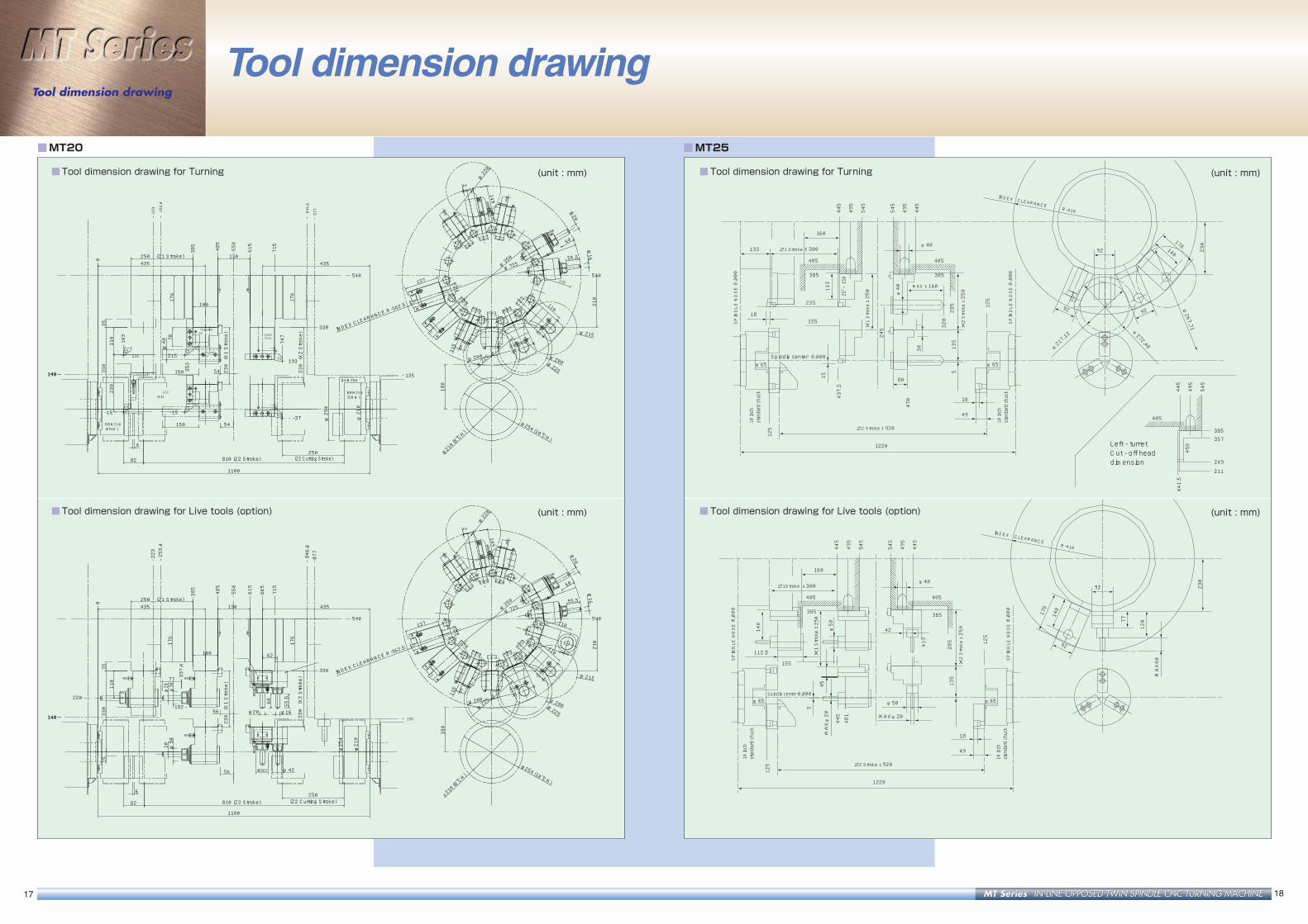
■MT20 / MT25
Tooling System &Tool dimension drawing
■Tool dimension drawing for Turning
■Tool dimension drawing for Live tools (option) (unit : mm)
Tooling System & Tool dimension drawing
IN-LINE OPPOSED TWIN SPINDLE CNC TURNING MACHINEIN-LINE OPPOSED TWIN SPINDLE CNC TURNING MACHINE
133
160
405
385
405
385
405
385357
249
211
113
25□×150
15
245
30
445
495
545
545
495
445
445
458
441.5
495
545
135
285 125
320
5
φ40
437.5
125
470
235
155
80
18
49
1220
18
Z1 Stroke
MAX:160
Spindle center 0.000φ65
Z2 Stroke:920
X1 Stroke:250
X2 Stroke:250
SPINDLE NOSE 0.000
SPINDLE NOSE 0.000
INDEX CLEARANCE R-410
230
10 inch
standard chuck
10 inch
standard chuck
φ65
:300φ40
φ217.12 φ
272.48
φ267.71
92 92
92 140
178
Left - turret Cut - off head dimension
155
112.5
160
405
42
385
405
385
5
45
140
445
495
545
545
495
445
135
285 125
445
413
481
125
MAXφ20
φ50
18
49
1220
Z1Stroke :300
Spindle center 0.000φ65
φ50
Z2 Stroke:920
X2 Stroke:250
SPINDLE NOSE 0.000
X1 Stroke:250
SPINDLE NOSE 0.000
INDEX CLEARANCE R-410
230
MAXφ20
φ65
φ40
92
92
77
120
MAX60
140
178
10 inch
standard chuck
10 inch
standard chuck
■MT25
■Tool dimension drawing for Turning
■ Tool dimension drawing for Live tools (option)
■MT20
(X2 Stroke)
230
(X1 Stroke)
230
810 (Z2 Stroke)
254
210
(Z1 Stroke)250
250
100
130
82
435
6
435
35
150
540
230
110
223
253.4
485
385
615
715
550
176
135
330
0
846.6
877
540
54150
110
110
149
137
140
55.5
60
φ200
φ225
210
115
φ725φ
350
180
16
20
φ225
φ215
φ220
φ200
(8"CH)
210
(10"CH)
254
747
353
103
1100
37
193215215
15 15
φ
φ
54
176
78φ40
-
140
330
2
φ
- -
φ
BHM250
HDTURNING
HDPLANE
TOOL
(SMW)BBM210
(SMW)BBM210
HDCUTOFF
(Z2 Cutting Stroke)
KNEE
φ
φ
INDEX CL
EARANCE R-362.5
1817
Tool dimension drawingTool dimension drawing
(X2 Stroke)
230(X1 Stroke)
230
810 (Z2 Stroke)
254
φ 210
φ
(Z1 Stroke)250
250 (Z2 Cutting Stroke)
100
130
82
435
10
62
6
16φ
435
20φ
35
56
540
110
223253.4
485
385
615
715
550
176
176
135140 330
0
846.6
877
15
330
540
77
20φ
56
110
110
149
137
140
55.5
60
φ200
φ225
210
115
φ725
INDEX CL
EARANCE R-362.5
φ350
180
16φ
20φ
φ225
φ215
2
φ220
φ200
(8"CH)
210
φ
(10"CH)
254φ
55.5
60
φ50
φ50
1100
φ42
337.4
665
220
182
(unit : mm) (unit : mm)
(unit : mm) (unit : mm)
■Tool dimension drawing for Turning
■Tool dimension drawing for Live tools (option)

IN-LINE OPPOSED TWIN SPINDLE CNC TURNING MACHINEIN-LINE OPPOSED TWIN SPINDLE CNC TURNING MACHINE 2019
SpecificationsMachine & CNC specifications
■Other CNC functions
● Optional block skip ● Dwell (G04; seconds unit)● Emergency stop ● Machine lock● Feed hold ● Dry run mode● Optional stop ● Single block mode● Program number search ● Sequence number display : 5 digit● Sequence number search ● Second reference point return● Decimal point designation/calculator type ● Chamfering and corner R● Circular radius R designation ● Diameter / radius designation● Auto coordinate system set ● Work cordinate system unit● Work cordinate system direct input ● Stored stroke limit● Data protect key switch ● Multiple repetitive cycle (G70 - G76)● Canned cycle for drilling (G80 - G89) ● Offset value program input (G10)● Nose radius compensation (G40 - G42) ● Display of run time and parts count● Background edit ● Synchronization M-code● Clock function ● Custom macro B
■CNC specifications
Contents Specifications
Number ofMT12 2 axes (X1, Z1) + 2 axes (X2, Z2)
axes MT20 Standard 2 axes (X1, Z1) + 2 axes (X2, Z2)controlled
MT25 Option 3 axes (X1, Y1, Z1) + 3 axes (X2, Y2, Z2)
X,Y,Z axes position feed back Absolute pulse coder
X-axis 0.001 mm (on diameter)
Least input increment Y-axis 0.001 mm [MT20,MT25] (option)
Z-axis 0.001 mm
X-axis 0.0005 mm/P
Least move increment Y-axis 0.001 mm/P [MT20,MT25] (option)
Z-axis 0.001 mm/P
G00 X- axis
Rapid traverse G00 Y- axis(option)
Traverse rateG00 Z- axis
Cutting feed rate G01 mm/rev, mm/min (inch/rev, inch/min)
Thread cutting F: 0.0001 - 500.0000 mm/rev
Continuous thread cutting Straight, taper, face thread
Manual jog feed rate 0 to 1260 mm/min
Manual handle feed rate 0.001 mm/div., 0.01 mm/div., 0.1 mm/div.
Cutting feed rate 0 to 110% (for every 10%)
Override Rapid feed rate 0/25/50/100%
Spindle speed 50 to 120% (for every 10%)
Tool function no. of sets of tool offsets T4 Digit (2+2) 32 sets
Assistant function M-code (3-digit)
Display unit 10.4" color LCD
Memory capacity 64K Byte (80 m each spindle)
Auto Input coding recognition EIA RS244, ISO 840 automatic judgment
Manual data input MDI Multi-block command input/running
Reference point return G27, G28
Program format Absolute/Increment commands in 1 block
Maximum number of programs 63
Program No. 10 Digit, Program name-31 characters
Subprogram 10 fold nesting
Canned cycle G90, G92, G94
Miscellaneous Alarm description display, Help function,Parameter setting display, Self-diagnosticsfunction, Alarm history display, Number ofrunning spindle rotation display, Runningspeed display
MT12 : 24,000 mm/minMT20 : 20,000 mm/minMT25 : 16,000 mm/min
MT20 : 20,000 mm/minMT25 : 10,000 mm/min
MT12 : 24,000 mm/minMT20 : 24,000 mm/minMT25 : 18,000 mm/min
Auto zero returnStandard X1, Z1, X2, Z2 - axis
Option X1, Y1, Z1, X2, Y2, Z2 - axis
Cut-off sensor Torque detection type
Work counter (LCD) 8 digit. Left/Right with preset function
Total counter (LCD) 8 digit. Left/Right
Soft tool counter (LCD) 6 digit. Left/Right 15 pairs
Foot switch Left/Right 1 each
Manual pulse generator 0.001 mm, 0.01 mm, 0.1 mm
Work light LED, 2 No. Light-up with power ON
Work light ON/OFF switch LCD soft switch
Coolant nozzle near chuck Left/Right one each (M8 coolant ON)
Coolant unit Coolant tank, pump, piping
Reader/Punch interface Memory Card
Help menu Operation, zero return information, M-code list
Alarm display Alarm contents, measures, concerned LS No.,
DGN No., are displayed on LCD
■Other standard functions
■Safety specifications
For EU countries, machines are built withCE-safety conformity.
* Machine appearance may differ to that shown in the photographs.
* All specifications are subject to change without notice.
■Live Tooling Specifications
■CNC Gantry Loader Specifications
Contents MT12 MT20 MT25
Maximum chuck sizeStandard φ 165 mm(6 inch) φ 210 mm(8 inch) φ254 mm(10 inch)
Option φ 210 mm(8 inch) ― ―
Number of turret stations 15 15 15
X-axis 200 mm 24 m/min 230 mm 20 m/min 250 mm 16 m/min
Z1-axis 200 mm 24 m/min 250 mm 24 m/min 300mm 18m/minSpecification of
Z2-axis 650 mm 24 m/min 850 mm 24 m/min 920 mm 18 m/mincutting axes for turret
(Work transfer:32 m/min) (Work transfer:32 m/min) (Work transfer:24 m/min)
Y-axis ― ±50 mm 20 m/min ± 60 mm 10 m/min
Use toolO.D. tool □ 20 mm □ 25 mm □ 25 mm
I.D. tool φ 40 mm φ 40 mm φ 40 mm
Spindle drive motorStandard 7.5 kW/30min x 2 15 kW/30min x 2 15 kW/30min x 2
Option 11 kW/30min x 2 18.5 kW/30min x 2 22 kW/30min(Left spindle only)
Standard A 45~ 4500 rpm 42~4200 rpm 25~ 2500 rpm
Spindle speed rangeStandard B 30~ 3000 rpm ― 35~ 3500 rpm
Standard C 60~ 6000 rpm―
(7.5kW)40~ 4000 rpm
Spindle diameter at Standard φ 90 mm φ 110 mm φ 110 mm
front bearing mounting Option ― ― φ 120 mm(Left spindle only)
Diameter of spindle boreStandard φ 62 mm φ 77 mm φ 77 mm
Option ― ― φ 83 mm(Left spindle only)
Spindle nose size JISA2-5 JISA2-5 JISA2-6
Spindle draw tube diameterStandard φ 52 mm φ 66 mm φ 66 mm
Option ― ― φ 72 mm(Left spindle only)
maximum diameter:Standard φ 51 mm φ 65 mm φ 65 mm
Maximum bar workpiece size maximum diameter:Option ― ― φ71 mm (Left spindle only)
maximum length 800 mm 1150 mm 1300 mm
Foot print 2700 mm x 1850 mm 2980 mm x 2100 mm 3700 mm x 2250 mm
Total weight (with tools, without loader) 5,200 kg 10,400 kg 10,000 kg
Total weight (with tools and loader) 5,600 kg 10,800 kg 10,400 kg
Contents MT12 MT20 MT25
Live tool drive motor 2.7 kW(12 Nm/continuous) 3.0 kW(12 Nm/continuous) 4.0 kW(22 Nm/continuous)
Maximum speed 4000 rpm 3600 rpm 3000 rpm
Maximum tool shank sizeMilling φ 16 mm φ20 mm φ 20 mm
Tapping M16 M16 M16
C-axis control Positioning Accuracy:± 0.015° Positioning Accuracy:±0.015° Positioning Accuracy:± 0.015°
Spindle positioning function Maximum speed 200 rpm 100 rpm 100 rpm
Least command increment 0.001° 0.001° 0.001°
Hydraulic brake torque185 Nm(18.9 kgf) 148 Nm(15.1 kgf) 185 Nm (18.9 kgf)
Spindle brake[4.4 Mpa(45 kgf/cm2)] [3.5 Mpa(35 kgf/cm2)] [3.5 Mpa(35 kgf/cm2)]
Additional air pressure―
17 Nm(1.7 kgf) 21 Nm(2.16 kgf)
brake torque [0.4 Mpa(4 kgf/cm2)] [0.4 Mpa(4 kgf/cm2)]
Contents MT12 MT20 MT25
Loader workpiece handling capacity (weight) 3.0 kg x 2 5.0 kg x 2 8.0 kg x 2
Loader workpiece handling capacity (size) φ 120 mm x 100 mm φ170 mm x 140 mm φ 220 mm x 170 mm
Z-axis(Left/Right)Stroke The gantry loader Z-axis stroke adjustable to layout.
Max. Speed 100 m/min 120 m/min 100 m/min
Stroke(3 Jaws type) 585 mm 666 mm 850 mmY-axis(Up/Down) Stroke(2 Jaws type) 766 mm
Max. Speed 100 m/min 110 m/min 70 m/min
X-axis(Front/Rear) Stroke ― 150 mm 150 mm
Max. Speed ― 35 m/min 30 m/min
α -axis Stroke 270° 270° 270°
Cycle time 1.5 sec/270° 1.5 sec/270° 1.5 sec/270°
Jaw Stroke Loader/ T/A unit φ 40 mm φ30 mm φ 36 mm
■Basic Machine Specifications
IN-LINE OPPOSED TWIN SPINDLE CNC TURNING MACHINEIN-LINE OPPOSED TWIN SPINDLE CNC TURNING MACHINE
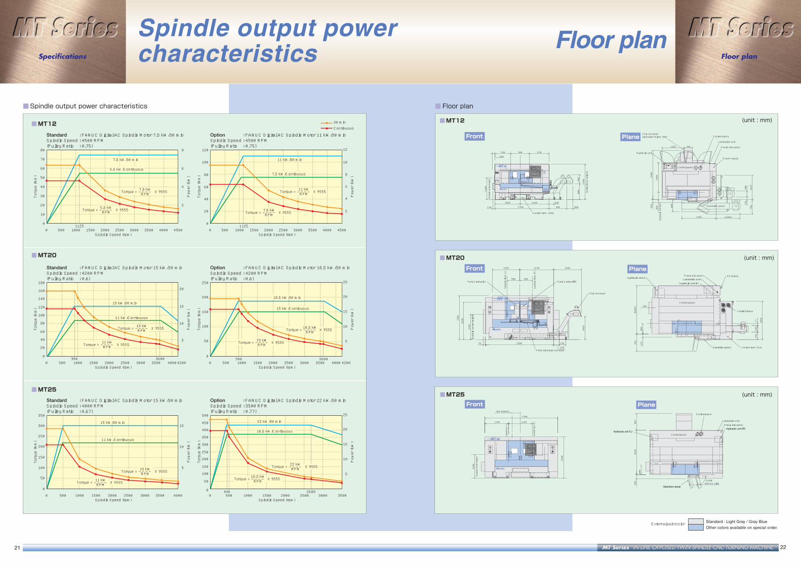
■ Floor plan
Spindle output powercharacteristics
2221
■Spindle output power characteristics
80
70
60
50
40
30
20
8
6
4
2
10
0
0 500 1000 15001125 1125
2000 2500 3000 3500 4000 4500
Torque (Nm)
Power (kW)
Spindle Speed (rpm)
7.5 kW/30 min
5.5 kW/Continuous
Torque = 7.5 kW X 9555 RPM
――――
Torque = 5.5 kW X 9555 RPM
――――
Standard : FANUC Digital AC Spindle Motor 7.5 kW/30 min Spindle Speed : 4500 RPM (Pulley Ratio : 0.75)
120
100
80
60
40
20
8
10
12
6
4
2
0
0 500 1000 1500 2000 2500 3000 3500 4000 4500
Torque (Nm)
Power (kW)
Spindle Speed (rpm)
11 kW/30 min
7.5 kW/Continuous
Torque = 11 kW X 9555 RPM
――――
Torque = 7.5 kW X 9555 RPM
――――
Option : FANUC Digital AC Spindle Motor 11 kW/30 min Spindle Speed : 4500 RPM (Pulley Ratio : 0.75)
180
160
140
120
100
80
60
40
20
15
10
5
20
0
0 500 1000 1500900 3600
2000 2500 3000 3500 40004200
Torque (Nm)
Power (kW)
Spindle Speed (rpm)
15 kW/30 min
11 kW/Continuous
Torque = 15 kW X 9555 RPM
――――
Torque = 11 kW X 9555 RPM
――――
Standard : FANUC Digital AC Spindle Motor 15 kW/30 min Spindle Speed : 4200 RPM (Pulley Ratio : 0.6)
250
200
150
100
50
15
20
25
10
5
0
0 500 1000900 3600
1500 2000 2500 3000 3500 4000 4200
Torque (Nm)
Power (kW)
Spindle Speed (rpm)
18.5 kW/30 min
15 kW/Continuous
Torque = 18.5 kW X 9555 RPM
――――
Torque = 15 kW X 9555 RPM
――――
Option : FANUC Digital AC Spindle Motor 18.5 kW/30 min Spindle Speed : 4200 RPM (Pulley Ratio : 0.6)
350
300
250
200
150
100
15
10
5
50
0
0 500 1000 1500 2000 2500 3000 3500 4000
Torque (Nm)
Power (kW)
Spindle Speed (rpm)
15 kW/30 min
11 kW/Continuous
Torque = 15 kW X 9555 RPM
――――
Torque = 11 kW X 9555 RPM
――――
Standard : FANUC Digital AC Spindle Motor 15 kW/30 min Spindle Speed : 4000 RPM (Pulley Ratio : 0.67)
500
450
400
350
300
250
200
150
100
50
15
20
25
10
5
00 500 1000
446 26801500 2000 2500 3000 3500
Torque (Nm)
Power (kW)
Spindle Speed (rpm)
22 kW/30 min
18.5 kW/Continuous
Torque = 22 kW X 9555 RPM
――――
Torque = 18.5 kW X 9555 RPM
――――
Option : FANUC Digital AC Spindle Motor 22 kW/30 min Spindle Speed : 3500 RPM (Pulley Ratio : 0.77)
30 minContinuous
■MT12
■MT20
■MT25
Floor planFloor plan
Specifications
■MT12
■MT25
(unit : mm)
■MT20 (unit : mm)
(unit : mm)
Coolant tank : 200L
(Spindle center height)
(Spindle center)
Chip conveyor discharge height : 800
(Safty fence height)
Coolant pump
Hydraulic unit
Lubrication unit
Pneumatic panel
Power supply
Operation panel
Control panel
1440
2700
1260
110
230
900 300
800
440
1100
790 940
130
970
360
14902480
1105 400
132
300
1237
750600
1725 )1200(
1790
135
(Spindle center height)
Parts Catcher(L) Parts Catcher(R)
Chip conveyor
Parts discharge conveyorOperation panel
Hydraulic unit (L)
Control panel
Pneumatic panelLubrication unit
Hydraulic unit (R)
Spindle face (L)
Spindle face (R)
Coolant pump
Coolant tank : 210L
Air supply
( 2095)
763
1206
1010
92
450
1630
2980
235
1902
1100
1205 1470
550550
333
1668
295
130
147
290
77
2250
500
857
205
Hydraulic unit (R)Pneumatic panel
Lubrication unit
C/L
Spindle face (L)
Spindle face (R)
Hydraulic unit (L)
Coolant pump
Operation panel400 mm slide
3700
1220 1190
420 (Stroke)
1200
Swing
2100
Control panel
(Spindle center height)
External paint color Standard : Light Gray / Gray Blue
Other colors available on special order.
Front Plane
Front Plane
Front Plane