Embed Size (px)
Citation preview

English
Manual
Vibration Control
Type 640
Vibration Velocity (mms rms)
Analoge Current Output 420 mA
Frequency Range 10 Hz1000 Hz
AttentionBefore Start-Up Procedure the Instruction Manual must be read and
understood
HAUBER-Elektronik GmbH
Should any question arise please contact
HAUBER-Elektronik GmbHFabrikstraszlige 6D-72622 NuumlrtingenGermanyPhone +49 (0) 7022 21750-0Fax +49 (0) 7022 21750-50infohauber-elektronikdewwwhauber-elektronikde
Instruction Manual
Edition 03082015
Vibration ControlType 640
StandardZone-1-21Zone-2-22
1 Safety Informations4
2 Instruction Manual Scope 5
3 The Vibration Control Type 6405
4 Intended Use 5
5 Documents and Certificates 5
6 Responsibility for the Safe Operation Disclaimer 5
7 Application Fields 6
8 Delivery Contents 6
9 Electrical Data 7
10 Mechanical Data9
11 Connections10
12 Mounting and Demounting 11
121 Fastening at the Mounting Surface 11
122 Zone-2-22 - Fastening Safety Clip Protective Cover 12
13 Installation and Start-Up 13
14 Maintenance and Repairs13
15 Grounding Concepts to avoid Ground Loops 14
HAUBER-Elektronik GmbH
3
Content
Standard Zone-1-21 Zone-2-22
HAUBER-Elektronik GmbH
1 Safety Informations
In General
The safety instructions serve the protection of persons and things from damage and danger that arise from not intended use and further misuse of products especially in explosion endangered areas Therefore read the instruction manual carefully before working with or starting-up the product To the operating personnel the instruction manual has to be accessable anytime
Before the starting-up or miscellaneous works with the product please check wether all the documents are available completely If not all the documents are committed completely or futher copies are required they can be obtained in different languages
Our product is designed to the latest state of the art Nevertheless there are a number of residual risks This means that each person in the operators firm concerned with mounting and dismounting installation start-up operating or maintanance of the product has to have read and understood the instruction manualThis means furthermore that each person in the operators firm concerned with mounting and dismounting installation start-up operating or maintanance of the product has to be an authorized expert familiar with the safety instructions for handling electrical components For handling ATEX-certified products within explosion endangered surroundings the expert in addition has to be familiar with the safety instructions relevant there
This symbol indicates an explosion hazard
Used Symbols
This symbol indicates a risk from electrical current
This symbol indicates a (non-safety relevant) information
4
HAUBER-Elektronik GmbH
5
2 Instruction Manual Scope
The present instruction manual of the Vibration Control Type 640 is applicable for the following variants Standard Zone-1-21 and Zone-2-22The functionality of the variants is identical In addition the variants have certifications and labellings that allow operation in explosion endangered areas (see chap 7 Operation Areas)
3 The Vibration control Type 640
The Vibration control Type 640 ist applied for the measurement of machines absolute bearing vibration referring to DIN ISO 10816 It offers the following features
bull Principle of operation Two-wire system
bull Measured Variable Root mean square (rms) of vibration velocity in mms
bull Analog Current Output Interference-free direct-current signal of 420 mA proportionately to the measuring range of the control
bull Cable break at the control cable detectable by a succeeding evaluation device Value of the direct current signal lt 35 mA
4 Intended Use
The Type 640 exclusively serves for the measurement of mechanical vibrations of machines and mechanical facilities The operation is valid exclusively within the specifications mentioned in this manual Main areas of application Industrial fans ventilators blowers electric motors pumps centrifuges seperators generators turbines and similar oscillatory mechanical equipment
Following Type 640 Documents und Certificates can be consulted on wwwhauber-elektronikde
EC-Conformity-Declaration EC-Type-Examination-Certificate ATEX-Zone 1 und 21 no PTB 06 ATEX 1072 Statement-of-Conformity ATEX-Zone 2 und 22 no LU 15 ATEX 0130X
5 Documents and Certificates
The correct layout of the electrical plant under conditions of explosion protection as well as the correct switch on procedure is the sole responsibility of the user of the plantThe current valid explosion protection rules and security regulations must be adhered to and must be under given circumstances checked by a competent person Should the plant on the order of the user be erected by a subcontractor the plant must only be switched on after the subcontractor has submitted an installation certificate as prove of the correct nature of the installation according to the relevant valid regulationsThe primary switch on of explosion protected plants or part of plants as well as the subsequent switch on after major adjustments or maintenance work must be reported to the relevant authorities by the owner
6 Responsibility for the Safe Operation Disclaimer
8 Delivery Contents
7 Application Fields
6
HAUBER-Elektronik GmbH
Variant Delivery Contents
Standard bull Vibration Sensor Type 640
bull Instruction Manual
Zone-1-21 bull Vibration Sensor Type 640
bull Integrated Cable Length 2 5 10 25 m
or on request
bull Instruction Manual
Zone-2-22 bull Vibration Sensor Type 640
bull Instruction Manual
bull Safety Clip
bull Protective Cover for M12-Plug
Available
Supplies
bull Evaluation Devices Types 651 652 656
bull Handheld Meter Type 641
bull Various Adapters eg M8 -gt M10
bull Allocable Mating Connector M12 8-pole
bull Connection Cable M12-Socket 4-pole
034 mm2
L= 2 m 5 m oder 10 m or on request
bull Magnet Foot
bull Rubber Protection Sleeve
bull EMC-Adapter
For OUTDOOR USE or with SPLASHWATER the Control for additional protection should be covered with the Rubber Protection Sleeve (see ldquoAvailable Suppliesldquo)
Gummischutztuumllle
Variante Application Fields Labelling
none
II 2 G Ex d IIC T4 Gb
II 2 D Ex tb IIIC T120 degC Db
II 3 G Ex nA IIC T4 Gc
II 3 D Ex tc IIIC T125 degC Dc
None explosion
endangered areasStandard
Explosion endangered
areas Zone 1 and 21
Explosion endangered
areas Zone 2 and 22
Zone-1-21
Zone-2-22
Measuring Range 0
Measuring accuracy 5
Transverse sensitivity lt 5
mms0 mms0 mms0 mms0 mms0 mms0 mms0 mms
Frequency range 10 Hz1000 Hz
Output signals 420 mA (Proportional to the Measuring Range)
Voltage supply 24V DC 10
Power input (max) 25 mA
BurdenLoad (max) 500 S
Fusing Microfuse (Time delay 32 mA breaking capacity C)
HAUBER-Elektronik GmbH
7
9 Electrical Data
Before Starting-Up the control the mains must be secured with a microfuse ( )
time delay 32 mA breaking capacity C
8163264
128256512
1000
Valid Operating Temperature Ranges of all Variants
Standard Zone-1-21 Zone-2-22
Ambient Temperature -20 degChellip+60 degC -20 degChellip+60 degC -20 degChellip+60 degC
Measuring Head-
Temperatur (at the Fastening)
-40 degChellip+85 degC -20 degChellip+100 degC -40 degChellip+100 degC
bull Each Type 640 has one of the listed measuring ranges
bull Further measuring ranges on request
bull Please indicate the measuring range in your order
HAUBER-Elektronik GmbH
8
Arbeitsbereich interner Sensorbaustein
0
20
40
60
80
100
120
140
160
180
200
0 100 200 300 400 500 600 700 800 900 1000
Frequenz (Hz)
Sc
hw
ing
ge
sc
hw
ind
igk
eit
(m
ms
)
Operating Range
Operating Range of Vibration Control Type 640
Reading example
Frequency Max measurable(Hz) Vibration Velocity 100 160 400 40 1000 18
The operating range is independent of the measuring range The diagram shows that with increasing frequency the height of the measurable vibration velocity decreases
Vib
rati
on
Velo
cit
y (
mm
s)
Frequency (Hz)
Frequency Range 10 Hz1000 Hz
- 4 0
- 3 5
- 3 0
- 2 5
- 2 0
- 1 5
- 1 0
- 5
0
5
1 1 0 1 0 0 1 0 0 0 1 0 0 0 0 H z
d B
Housing Material Stainless Steel V2A material no 14305
M12-connector CuZn (brass) nickel plated
Cable gland Stainless Steel V2A
Fastening Wrench Size 24 (hexagon) M8 x 8 mm Threat pitch 125 mm
Weight ca 150 g
Protection Style IP 67
Securing The control must be grounded viathe M8 fastening (see chapt12)
HAUBER-Elektronik GmbH
9
10 Mechanical Data
Housing Dimensions and Direction of Measurement
Direction of =
Direction of Measurement
Fastening
Standard Zone-2-22 Zone-1-21
M12-Plug
Connection Cable
Direction of Measurement
50 10 8
M8 Oslash28
2
7175
Oslash5
Oslash1
65
Cable Gland
Measures in mm
93
59
69 8
M8 Oslash2
8
Direction of Measurement
Thread-Cone-Fastening
Standard with Thread-Cone
M12-Plug
Direction of Measurement
HAUBER-Elektronik GmbH
10
Connection Plan for all 3 Variants
11 Connections
Connection Cable Socket(Supplies)
M12-Plug
M12-Plug 4-polePin allocation see Connection Plan
Connection cable socket M12 4-pole 034 mmsup2 Pin allocation see Connection Plan
Standard Zone-2-22 Zone-1-21
Connection Cable
PUR-sheathed-cable Oslash ca 65 mm4-pole 025 mmsup2Pin allocation see Connection Plan
2
34
1
Evaluation-Device
Type 640
1
2
3
4
BN
WH
BU
BK
BN
BU
The system works according to Two-wire-technology This means the overall function (Power supply and Current-signal) is realized using 2 wires (Pin 1 und Pin 3)
To avoid capacitive Coupling Interferences the Pins 2 and 4 have to stay open resp free
The evaluation of the 420 mA current signal is done eg via Amperemeter or PLC-control
11
HAUBER-Elektronik GmbH
12 Mounting and Dismounting
Mounting and Dismounting works at and with the control may only be executed by an authorized expert familiar with the safety instructions for handling electrical components For handling ATEX-certified controls within explosion endangered surroundings the expert in addition has to be familiar with the safety instructions relevant there
Preconditions
Mounting surface clean and flat ie free from paint rust etcThreaded hole at the Mounting surface
Depth 10 mm Thread M8
Tighten control friction-locked into the threated hole of the mounting surface
Working Steps
Allen wrench SW24
Tools and Materials
Before mounting and dismounting works the control has to be seperated from the mains Seperated plug and socket devices always have to be disconnected from the mains Otherwise danger of explosion because of sparkling when operating ATEX-certified controls in explosion endangered areas
The Sonsor housing must be earthed via ist fastening - i e via machine earth or via a seperate earth wire (PE)
121 Fastening at the Mounting Surface
To obtain exact measuring values the control has to be tighten friction-locked at the mounting surface
Avoid Auxiliary Constructions If unavoidable implement it as stiff as possible
HAUBER-Elektronik GmbH
12
Half Shell Arrow and Eye
Sign
Fastened Safety Clip
Protective Cover Fastened Protective Cover
Safety Clip
Plug in the connection cable socket into the M12-plug completely(Pay attention to the code cam)
122 Zone-2-22 - Fastening Safety Clip Protective Cover
1 Disconnect mains electric circuit 2 Separate both shell halves of the fuse clip with a screw driver 3 Fasten protective cover and skrew it tightly onto the control plug
1
2
3
Tighten firmly the lock-nut of the connection cable socket by hand
Fasten the safety clip against accidental disconnection of the plug connection 1 Put both shell halves of the safety clip around the plug connection 2 Press together by hand both shell halves of the safety clip until the
catch lock snaps in 3 Put the arrow connected to one shell halve around the cable then stick
it through the eye on the other end so that the notice sign is readablealongside the cable
Fastening Protective Cover
Fastening Safety Clip
Disassemble the safety clip and mount the protective cover
The operation of variant Zone-2-22 is not permitted without the Safety Clip to avoid accidently disconnecting the plug-in connection Otherwise danger of explosion because of sparkling when operating in explosion endangered areas
After disconnecting the plug connection the protective cover has to be mounted
HAUBER-Elektronik GmbH
13
13 Installation and Start-Up
14 Maintenance and Repair
Note The Type 640 and its variants are maintenance free
Errortable
Installing and starting-up the control may only be executed by an authorized expert familiar with the safety instructions for handling electrical components For handling ATEX-certified controls within explosion endangered surroundings the expert in addition has to be familiar with the safety instructions relevant there
Prior to starting-up the control the mains must be secured with a microfuse ()
time delay 32 mA breaking capacity C
The connection cable and possible extension cables must be protected against electrical influenzes and mechanical damages Here local regulations and commissions absolutely have to be considered
Repairing the control may only be executed by an authorized expert familiar with the safety instructions for handling electrical components For handling ATEX-certified controls within explosion endangered surroundings the expert in addition has to be familiar with the safety instructions relevant there
Prior to repair and cleaning works the control has to be seperated from the mains Seperated plug and socket devices always have to stay disconnected from the mains Otherwise danger of explosion because of sparkling when operating ATEX-certified controls in explosion endangered areas
Defective connection cables immediately have to be replaced explosion because of sparkling when operating ATEX-certified controls in explosion endangered areas
Otherwise danger of
A defective control has to be changed completely
Error Cause Activity
No Power Supply Check Power Supply andor
Connection Cable
Connection Cable interrupted Replace Connection Cable
Fuse defective Replace Fuse
Connection wrong Polarity Provide correct Polarity
Control defektive Replace Control
Control mounting not friction-locked Mount Control friction-locked
Control mounting at wrong position Mount Control at correct postion
EMC-Problems see Cap 15 Grounding
Concepts
Wrong measured Value
No measured Value
HAUBER-Elektronik GmbH
14
15 Grounding Concepts to avoid Ground Loops
Ground loops are among the most frequent problems for measurement setups with sensitive sensor technology They arise through unwanted potential differences inside the current circuit between sensor and evaluation device As countermeasure we recommend our Standard- Grounding Concept or according to application our Alternative-Grounding Concept
Alternativ-Grounding Concept
In the Alternative-Grounding Concept the shield of the sensor cable has connection to the sensor-hausing (dotted circle) The sensor hausing is decoupled from the machine ground via EMC-adapter (black)
Machine Evaluation Device
+24V 420mA
Sensor Cable
Machine
+24V 420mA
Sensor Cable
Evaluation Deviceeg AmperemeterPLC-Control
Standard-Grounding Concept
In the Standard-Grounding Concept the shield of the sensor cable has no connection to the sensor-hausing (dotted circle) The sensor housing lies on the same potential as the machine ground
Maschine ground
Maschine Ground
Sensor-Housing
EMC-Adapter
Please indicate in your order if you decide to use the Alternative-Grounding ConceptWe will then offer to you the according Sensor Cable and EMC-Adapter
Evaluation Device
Evaluation Deviceeg AmperemeterPLC-Control
Shield
ShieldSensor-Housing

HAUBER-Elektronik GmbH
5
2 Instruction Manual Scope
The present instruction manual of the Vibration Control Type 640 is applicable for the following variants Standard Zone-1-21 and Zone-2-22The functionality of the variants is identical In addition the variants have certifications and labellings that allow operation in explosion endangered areas (see chap 7 Operation Areas)
3 The Vibration control Type 640
The Vibration control Type 640 ist applied for the measurement of machines absolute bearing vibration referring to DIN ISO 10816 It offers the following features
bull Principle of operation Two-wire system
bull Measured Variable Root mean square (rms) of vibration velocity in mms
bull Analog Current Output Interference-free direct-current signal of 420 mA proportionately to the measuring range of the control
bull Cable break at the control cable detectable by a succeeding evaluation device Value of the direct current signal lt 35 mA
4 Intended Use
The Type 640 exclusively serves for the measurement of mechanical vibrations of machines and mechanical facilities The operation is valid exclusively within the specifications mentioned in this manual Main areas of application Industrial fans ventilators blowers electric motors pumps centrifuges seperators generators turbines and similar oscillatory mechanical equipment
Following Type 640 Documents und Certificates can be consulted on wwwhauber-elektronikde
EC-Conformity-Declaration EC-Type-Examination-Certificate ATEX-Zone 1 und 21 no PTB 06 ATEX 1072 Statement-of-Conformity ATEX-Zone 2 und 22 no LU 15 ATEX 0130X
5 Documents and Certificates
The correct layout of the electrical plant under conditions of explosion protection as well as the correct switch on procedure is the sole responsibility of the user of the plantThe current valid explosion protection rules and security regulations must be adhered to and must be under given circumstances checked by a competent person Should the plant on the order of the user be erected by a subcontractor the plant must only be switched on after the subcontractor has submitted an installation certificate as prove of the correct nature of the installation according to the relevant valid regulationsThe primary switch on of explosion protected plants or part of plants as well as the subsequent switch on after major adjustments or maintenance work must be reported to the relevant authorities by the owner
6 Responsibility for the Safe Operation Disclaimer
8 Delivery Contents
7 Application Fields
6
HAUBER-Elektronik GmbH
Variant Delivery Contents
Standard bull Vibration Sensor Type 640
bull Instruction Manual
Zone-1-21 bull Vibration Sensor Type 640
bull Integrated Cable Length 2 5 10 25 m
or on request
bull Instruction Manual
Zone-2-22 bull Vibration Sensor Type 640
bull Instruction Manual
bull Safety Clip
bull Protective Cover for M12-Plug
Available
Supplies
bull Evaluation Devices Types 651 652 656
bull Handheld Meter Type 641
bull Various Adapters eg M8 -gt M10
bull Allocable Mating Connector M12 8-pole
bull Connection Cable M12-Socket 4-pole
034 mm2
L= 2 m 5 m oder 10 m or on request
bull Magnet Foot
bull Rubber Protection Sleeve
bull EMC-Adapter
For OUTDOOR USE or with SPLASHWATER the Control for additional protection should be covered with the Rubber Protection Sleeve (see ldquoAvailable Suppliesldquo)
Gummischutztuumllle
Variante Application Fields Labelling
none
II 2 G Ex d IIC T4 Gb
II 2 D Ex tb IIIC T120 degC Db
II 3 G Ex nA IIC T4 Gc
II 3 D Ex tc IIIC T125 degC Dc
None explosion
endangered areasStandard
Explosion endangered
areas Zone 1 and 21
Explosion endangered
areas Zone 2 and 22
Zone-1-21
Zone-2-22
Measuring Range 0
Measuring accuracy 5
Transverse sensitivity lt 5
mms0 mms0 mms0 mms0 mms0 mms0 mms0 mms
Frequency range 10 Hz1000 Hz
Output signals 420 mA (Proportional to the Measuring Range)
Voltage supply 24V DC 10
Power input (max) 25 mA
BurdenLoad (max) 500 S
Fusing Microfuse (Time delay 32 mA breaking capacity C)
HAUBER-Elektronik GmbH
7
9 Electrical Data
Before Starting-Up the control the mains must be secured with a microfuse ( )
time delay 32 mA breaking capacity C
8163264
128256512
1000
Valid Operating Temperature Ranges of all Variants
Standard Zone-1-21 Zone-2-22
Ambient Temperature -20 degChellip+60 degC -20 degChellip+60 degC -20 degChellip+60 degC
Measuring Head-
Temperatur (at the Fastening)
-40 degChellip+85 degC -20 degChellip+100 degC -40 degChellip+100 degC
bull Each Type 640 has one of the listed measuring ranges
bull Further measuring ranges on request
bull Please indicate the measuring range in your order
HAUBER-Elektronik GmbH
8
Arbeitsbereich interner Sensorbaustein
0
20
40
60
80
100
120
140
160
180
200
0 100 200 300 400 500 600 700 800 900 1000
Frequenz (Hz)
Sc
hw
ing
ge
sc
hw
ind
igk
eit
(m
ms
)
Operating Range
Operating Range of Vibration Control Type 640
Reading example
Frequency Max measurable(Hz) Vibration Velocity 100 160 400 40 1000 18
The operating range is independent of the measuring range The diagram shows that with increasing frequency the height of the measurable vibration velocity decreases
Vib
rati
on
Velo
cit
y (
mm
s)
Frequency (Hz)
Frequency Range 10 Hz1000 Hz
- 4 0
- 3 5
- 3 0
- 2 5
- 2 0
- 1 5
- 1 0
- 5
0
5
1 1 0 1 0 0 1 0 0 0 1 0 0 0 0 H z
d B
Housing Material Stainless Steel V2A material no 14305
M12-connector CuZn (brass) nickel plated
Cable gland Stainless Steel V2A
Fastening Wrench Size 24 (hexagon) M8 x 8 mm Threat pitch 125 mm
Weight ca 150 g
Protection Style IP 67
Securing The control must be grounded viathe M8 fastening (see chapt12)
HAUBER-Elektronik GmbH
9
10 Mechanical Data
Housing Dimensions and Direction of Measurement
Direction of =
Direction of Measurement
Fastening
Standard Zone-2-22 Zone-1-21
M12-Plug
Connection Cable
Direction of Measurement
50 10 8
M8 Oslash28
2
7175
Oslash5
Oslash1
65
Cable Gland
Measures in mm
93
59
69 8
M8 Oslash2
8
Direction of Measurement
Thread-Cone-Fastening
Standard with Thread-Cone
M12-Plug
Direction of Measurement
HAUBER-Elektronik GmbH
10
Connection Plan for all 3 Variants
11 Connections
Connection Cable Socket(Supplies)
M12-Plug
M12-Plug 4-polePin allocation see Connection Plan
Connection cable socket M12 4-pole 034 mmsup2 Pin allocation see Connection Plan
Standard Zone-2-22 Zone-1-21
Connection Cable
PUR-sheathed-cable Oslash ca 65 mm4-pole 025 mmsup2Pin allocation see Connection Plan
2
34
1
Evaluation-Device
Type 640
1
2
3
4
BN
WH
BU
BK
BN
BU
The system works according to Two-wire-technology This means the overall function (Power supply and Current-signal) is realized using 2 wires (Pin 1 und Pin 3)
To avoid capacitive Coupling Interferences the Pins 2 and 4 have to stay open resp free
The evaluation of the 420 mA current signal is done eg via Amperemeter or PLC-control
11
HAUBER-Elektronik GmbH
12 Mounting and Dismounting
Mounting and Dismounting works at and with the control may only be executed by an authorized expert familiar with the safety instructions for handling electrical components For handling ATEX-certified controls within explosion endangered surroundings the expert in addition has to be familiar with the safety instructions relevant there
Preconditions
Mounting surface clean and flat ie free from paint rust etcThreaded hole at the Mounting surface
Depth 10 mm Thread M8
Tighten control friction-locked into the threated hole of the mounting surface
Working Steps
Allen wrench SW24
Tools and Materials
Before mounting and dismounting works the control has to be seperated from the mains Seperated plug and socket devices always have to be disconnected from the mains Otherwise danger of explosion because of sparkling when operating ATEX-certified controls in explosion endangered areas
The Sonsor housing must be earthed via ist fastening - i e via machine earth or via a seperate earth wire (PE)
121 Fastening at the Mounting Surface
To obtain exact measuring values the control has to be tighten friction-locked at the mounting surface
Avoid Auxiliary Constructions If unavoidable implement it as stiff as possible
HAUBER-Elektronik GmbH
12
Half Shell Arrow and Eye
Sign
Fastened Safety Clip
Protective Cover Fastened Protective Cover
Safety Clip
Plug in the connection cable socket into the M12-plug completely(Pay attention to the code cam)
122 Zone-2-22 - Fastening Safety Clip Protective Cover
1 Disconnect mains electric circuit 2 Separate both shell halves of the fuse clip with a screw driver 3 Fasten protective cover and skrew it tightly onto the control plug
1
2
3
Tighten firmly the lock-nut of the connection cable socket by hand
Fasten the safety clip against accidental disconnection of the plug connection 1 Put both shell halves of the safety clip around the plug connection 2 Press together by hand both shell halves of the safety clip until the
catch lock snaps in 3 Put the arrow connected to one shell halve around the cable then stick
it through the eye on the other end so that the notice sign is readablealongside the cable
Fastening Protective Cover
Fastening Safety Clip
Disassemble the safety clip and mount the protective cover
The operation of variant Zone-2-22 is not permitted without the Safety Clip to avoid accidently disconnecting the plug-in connection Otherwise danger of explosion because of sparkling when operating in explosion endangered areas
After disconnecting the plug connection the protective cover has to be mounted
HAUBER-Elektronik GmbH
13
13 Installation and Start-Up
14 Maintenance and Repair
Note The Type 640 and its variants are maintenance free
Errortable
Installing and starting-up the control may only be executed by an authorized expert familiar with the safety instructions for handling electrical components For handling ATEX-certified controls within explosion endangered surroundings the expert in addition has to be familiar with the safety instructions relevant there
Prior to starting-up the control the mains must be secured with a microfuse ()
time delay 32 mA breaking capacity C
The connection cable and possible extension cables must be protected against electrical influenzes and mechanical damages Here local regulations and commissions absolutely have to be considered
Repairing the control may only be executed by an authorized expert familiar with the safety instructions for handling electrical components For handling ATEX-certified controls within explosion endangered surroundings the expert in addition has to be familiar with the safety instructions relevant there
Prior to repair and cleaning works the control has to be seperated from the mains Seperated plug and socket devices always have to stay disconnected from the mains Otherwise danger of explosion because of sparkling when operating ATEX-certified controls in explosion endangered areas
Defective connection cables immediately have to be replaced explosion because of sparkling when operating ATEX-certified controls in explosion endangered areas
Otherwise danger of
A defective control has to be changed completely
Error Cause Activity
No Power Supply Check Power Supply andor
Connection Cable
Connection Cable interrupted Replace Connection Cable
Fuse defective Replace Fuse
Connection wrong Polarity Provide correct Polarity
Control defektive Replace Control
Control mounting not friction-locked Mount Control friction-locked
Control mounting at wrong position Mount Control at correct postion
EMC-Problems see Cap 15 Grounding
Concepts
Wrong measured Value
No measured Value
HAUBER-Elektronik GmbH
14
15 Grounding Concepts to avoid Ground Loops
Ground loops are among the most frequent problems for measurement setups with sensitive sensor technology They arise through unwanted potential differences inside the current circuit between sensor and evaluation device As countermeasure we recommend our Standard- Grounding Concept or according to application our Alternative-Grounding Concept
Alternativ-Grounding Concept
In the Alternative-Grounding Concept the shield of the sensor cable has connection to the sensor-hausing (dotted circle) The sensor hausing is decoupled from the machine ground via EMC-adapter (black)
Machine Evaluation Device
+24V 420mA
Sensor Cable
Machine
+24V 420mA
Sensor Cable
Evaluation Deviceeg AmperemeterPLC-Control
Standard-Grounding Concept
In the Standard-Grounding Concept the shield of the sensor cable has no connection to the sensor-hausing (dotted circle) The sensor housing lies on the same potential as the machine ground
Maschine ground
Maschine Ground
Sensor-Housing
EMC-Adapter
Please indicate in your order if you decide to use the Alternative-Grounding ConceptWe will then offer to you the according Sensor Cable and EMC-Adapter
Evaluation Device
Evaluation Deviceeg AmperemeterPLC-Control
Shield
ShieldSensor-Housing
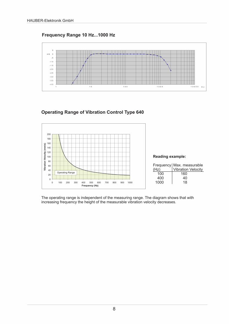
HAUBER-Elektronik GmbH
8
Arbeitsbereich interner Sensorbaustein
0
20
40
60
80
100
120
140
160
180
200
0 100 200 300 400 500 600 700 800 900 1000
Frequenz (Hz)
Sc
hw
ing
ge
sc
hw
ind
igk
eit
(m
ms
)
Operating Range
Operating Range of Vibration Control Type 640
Reading example
Frequency Max measurable(Hz) Vibration Velocity 100 160 400 40 1000 18
The operating range is independent of the measuring range The diagram shows that with increasing frequency the height of the measurable vibration velocity decreases
Vib
rati
on
Velo
cit
y (
mm
s)
Frequency (Hz)
Frequency Range 10 Hz1000 Hz
- 4 0
- 3 5
- 3 0
- 2 5
- 2 0
- 1 5
- 1 0
- 5
0
5
1 1 0 1 0 0 1 0 0 0 1 0 0 0 0 H z
d B
Housing Material Stainless Steel V2A material no 14305
M12-connector CuZn (brass) nickel plated
Cable gland Stainless Steel V2A
Fastening Wrench Size 24 (hexagon) M8 x 8 mm Threat pitch 125 mm
Weight ca 150 g
Protection Style IP 67
Securing The control must be grounded viathe M8 fastening (see chapt12)
HAUBER-Elektronik GmbH
9
10 Mechanical Data
Housing Dimensions and Direction of Measurement
Direction of =
Direction of Measurement
Fastening
Standard Zone-2-22 Zone-1-21
M12-Plug
Connection Cable
Direction of Measurement
50 10 8
M8 Oslash28
2
7175
Oslash5
Oslash1
65
Cable Gland
Measures in mm
93
59
69 8
M8 Oslash2
8
Direction of Measurement
Thread-Cone-Fastening
Standard with Thread-Cone
M12-Plug
Direction of Measurement
HAUBER-Elektronik GmbH
10
Connection Plan for all 3 Variants
11 Connections
Connection Cable Socket(Supplies)
M12-Plug
M12-Plug 4-polePin allocation see Connection Plan
Connection cable socket M12 4-pole 034 mmsup2 Pin allocation see Connection Plan
Standard Zone-2-22 Zone-1-21
Connection Cable
PUR-sheathed-cable Oslash ca 65 mm4-pole 025 mmsup2Pin allocation see Connection Plan
2
34
1
Evaluation-Device
Type 640
1
2
3
4
BN
WH
BU
BK
BN
BU
The system works according to Two-wire-technology This means the overall function (Power supply and Current-signal) is realized using 2 wires (Pin 1 und Pin 3)
To avoid capacitive Coupling Interferences the Pins 2 and 4 have to stay open resp free
The evaluation of the 420 mA current signal is done eg via Amperemeter or PLC-control
11
HAUBER-Elektronik GmbH
12 Mounting and Dismounting
Mounting and Dismounting works at and with the control may only be executed by an authorized expert familiar with the safety instructions for handling electrical components For handling ATEX-certified controls within explosion endangered surroundings the expert in addition has to be familiar with the safety instructions relevant there
Preconditions
Mounting surface clean and flat ie free from paint rust etcThreaded hole at the Mounting surface
Depth 10 mm Thread M8
Tighten control friction-locked into the threated hole of the mounting surface
Working Steps
Allen wrench SW24
Tools and Materials
Before mounting and dismounting works the control has to be seperated from the mains Seperated plug and socket devices always have to be disconnected from the mains Otherwise danger of explosion because of sparkling when operating ATEX-certified controls in explosion endangered areas
The Sonsor housing must be earthed via ist fastening - i e via machine earth or via a seperate earth wire (PE)
121 Fastening at the Mounting Surface
To obtain exact measuring values the control has to be tighten friction-locked at the mounting surface
Avoid Auxiliary Constructions If unavoidable implement it as stiff as possible
HAUBER-Elektronik GmbH
12
Half Shell Arrow and Eye
Sign
Fastened Safety Clip
Protective Cover Fastened Protective Cover
Safety Clip
Plug in the connection cable socket into the M12-plug completely(Pay attention to the code cam)
122 Zone-2-22 - Fastening Safety Clip Protective Cover
1 Disconnect mains electric circuit 2 Separate both shell halves of the fuse clip with a screw driver 3 Fasten protective cover and skrew it tightly onto the control plug
1
2
3
Tighten firmly the lock-nut of the connection cable socket by hand
Fasten the safety clip against accidental disconnection of the plug connection 1 Put both shell halves of the safety clip around the plug connection 2 Press together by hand both shell halves of the safety clip until the
catch lock snaps in 3 Put the arrow connected to one shell halve around the cable then stick
it through the eye on the other end so that the notice sign is readablealongside the cable
Fastening Protective Cover
Fastening Safety Clip
Disassemble the safety clip and mount the protective cover
The operation of variant Zone-2-22 is not permitted without the Safety Clip to avoid accidently disconnecting the plug-in connection Otherwise danger of explosion because of sparkling when operating in explosion endangered areas
After disconnecting the plug connection the protective cover has to be mounted
HAUBER-Elektronik GmbH
13
13 Installation and Start-Up
14 Maintenance and Repair
Note The Type 640 and its variants are maintenance free
Errortable
Installing and starting-up the control may only be executed by an authorized expert familiar with the safety instructions for handling electrical components For handling ATEX-certified controls within explosion endangered surroundings the expert in addition has to be familiar with the safety instructions relevant there
Prior to starting-up the control the mains must be secured with a microfuse ()
time delay 32 mA breaking capacity C
The connection cable and possible extension cables must be protected against electrical influenzes and mechanical damages Here local regulations and commissions absolutely have to be considered
Repairing the control may only be executed by an authorized expert familiar with the safety instructions for handling electrical components For handling ATEX-certified controls within explosion endangered surroundings the expert in addition has to be familiar with the safety instructions relevant there
Prior to repair and cleaning works the control has to be seperated from the mains Seperated plug and socket devices always have to stay disconnected from the mains Otherwise danger of explosion because of sparkling when operating ATEX-certified controls in explosion endangered areas
Defective connection cables immediately have to be replaced explosion because of sparkling when operating ATEX-certified controls in explosion endangered areas
Otherwise danger of
A defective control has to be changed completely
Error Cause Activity
No Power Supply Check Power Supply andor
Connection Cable
Connection Cable interrupted Replace Connection Cable
Fuse defective Replace Fuse
Connection wrong Polarity Provide correct Polarity
Control defektive Replace Control
Control mounting not friction-locked Mount Control friction-locked
Control mounting at wrong position Mount Control at correct postion
EMC-Problems see Cap 15 Grounding
Concepts
Wrong measured Value
No measured Value
HAUBER-Elektronik GmbH
14
15 Grounding Concepts to avoid Ground Loops
Ground loops are among the most frequent problems for measurement setups with sensitive sensor technology They arise through unwanted potential differences inside the current circuit between sensor and evaluation device As countermeasure we recommend our Standard- Grounding Concept or according to application our Alternative-Grounding Concept
Alternativ-Grounding Concept
In the Alternative-Grounding Concept the shield of the sensor cable has connection to the sensor-hausing (dotted circle) The sensor hausing is decoupled from the machine ground via EMC-adapter (black)
Machine Evaluation Device
+24V 420mA
Sensor Cable
Machine
+24V 420mA
Sensor Cable
Evaluation Deviceeg AmperemeterPLC-Control
Standard-Grounding Concept
In the Standard-Grounding Concept the shield of the sensor cable has no connection to the sensor-hausing (dotted circle) The sensor housing lies on the same potential as the machine ground
Maschine ground
Maschine Ground
Sensor-Housing
EMC-Adapter
Please indicate in your order if you decide to use the Alternative-Grounding ConceptWe will then offer to you the according Sensor Cable and EMC-Adapter
Evaluation Device
Evaluation Deviceeg AmperemeterPLC-Control
Shield
ShieldSensor-Housing

HAUBER-Elektronik GmbH
10
Connection Plan for all 3 Variants
11 Connections
Connection Cable Socket(Supplies)
M12-Plug
M12-Plug 4-polePin allocation see Connection Plan
Connection cable socket M12 4-pole 034 mmsup2 Pin allocation see Connection Plan
Standard Zone-2-22 Zone-1-21
Connection Cable
PUR-sheathed-cable Oslash ca 65 mm4-pole 025 mmsup2Pin allocation see Connection Plan
2
34
1
Evaluation-Device
Type 640
1
2
3
4
BN
WH
BU
BK
BN
BU
The system works according to Two-wire-technology This means the overall function (Power supply and Current-signal) is realized using 2 wires (Pin 1 und Pin 3)
To avoid capacitive Coupling Interferences the Pins 2 and 4 have to stay open resp free
The evaluation of the 420 mA current signal is done eg via Amperemeter or PLC-control
11
HAUBER-Elektronik GmbH
12 Mounting and Dismounting
Mounting and Dismounting works at and with the control may only be executed by an authorized expert familiar with the safety instructions for handling electrical components For handling ATEX-certified controls within explosion endangered surroundings the expert in addition has to be familiar with the safety instructions relevant there
Preconditions
Mounting surface clean and flat ie free from paint rust etcThreaded hole at the Mounting surface
Depth 10 mm Thread M8
Tighten control friction-locked into the threated hole of the mounting surface
Working Steps
Allen wrench SW24
Tools and Materials
Before mounting and dismounting works the control has to be seperated from the mains Seperated plug and socket devices always have to be disconnected from the mains Otherwise danger of explosion because of sparkling when operating ATEX-certified controls in explosion endangered areas
The Sonsor housing must be earthed via ist fastening - i e via machine earth or via a seperate earth wire (PE)
121 Fastening at the Mounting Surface
To obtain exact measuring values the control has to be tighten friction-locked at the mounting surface
Avoid Auxiliary Constructions If unavoidable implement it as stiff as possible
HAUBER-Elektronik GmbH
12
Half Shell Arrow and Eye
Sign
Fastened Safety Clip
Protective Cover Fastened Protective Cover
Safety Clip
Plug in the connection cable socket into the M12-plug completely(Pay attention to the code cam)
122 Zone-2-22 - Fastening Safety Clip Protective Cover
1 Disconnect mains electric circuit 2 Separate both shell halves of the fuse clip with a screw driver 3 Fasten protective cover and skrew it tightly onto the control plug
1
2
3
Tighten firmly the lock-nut of the connection cable socket by hand
Fasten the safety clip against accidental disconnection of the plug connection 1 Put both shell halves of the safety clip around the plug connection 2 Press together by hand both shell halves of the safety clip until the
catch lock snaps in 3 Put the arrow connected to one shell halve around the cable then stick
it through the eye on the other end so that the notice sign is readablealongside the cable
Fastening Protective Cover
Fastening Safety Clip
Disassemble the safety clip and mount the protective cover
The operation of variant Zone-2-22 is not permitted without the Safety Clip to avoid accidently disconnecting the plug-in connection Otherwise danger of explosion because of sparkling when operating in explosion endangered areas
After disconnecting the plug connection the protective cover has to be mounted
HAUBER-Elektronik GmbH
13
13 Installation and Start-Up
14 Maintenance and Repair
Note The Type 640 and its variants are maintenance free
Errortable
Installing and starting-up the control may only be executed by an authorized expert familiar with the safety instructions for handling electrical components For handling ATEX-certified controls within explosion endangered surroundings the expert in addition has to be familiar with the safety instructions relevant there
Prior to starting-up the control the mains must be secured with a microfuse ()
time delay 32 mA breaking capacity C
The connection cable and possible extension cables must be protected against electrical influenzes and mechanical damages Here local regulations and commissions absolutely have to be considered
Repairing the control may only be executed by an authorized expert familiar with the safety instructions for handling electrical components For handling ATEX-certified controls within explosion endangered surroundings the expert in addition has to be familiar with the safety instructions relevant there
Prior to repair and cleaning works the control has to be seperated from the mains Seperated plug and socket devices always have to stay disconnected from the mains Otherwise danger of explosion because of sparkling when operating ATEX-certified controls in explosion endangered areas
Defective connection cables immediately have to be replaced explosion because of sparkling when operating ATEX-certified controls in explosion endangered areas
Otherwise danger of
A defective control has to be changed completely
Error Cause Activity
No Power Supply Check Power Supply andor
Connection Cable
Connection Cable interrupted Replace Connection Cable
Fuse defective Replace Fuse
Connection wrong Polarity Provide correct Polarity
Control defektive Replace Control
Control mounting not friction-locked Mount Control friction-locked
Control mounting at wrong position Mount Control at correct postion
EMC-Problems see Cap 15 Grounding
Concepts
Wrong measured Value
No measured Value
HAUBER-Elektronik GmbH
14
15 Grounding Concepts to avoid Ground Loops
Ground loops are among the most frequent problems for measurement setups with sensitive sensor technology They arise through unwanted potential differences inside the current circuit between sensor and evaluation device As countermeasure we recommend our Standard- Grounding Concept or according to application our Alternative-Grounding Concept
Alternativ-Grounding Concept
In the Alternative-Grounding Concept the shield of the sensor cable has connection to the sensor-hausing (dotted circle) The sensor hausing is decoupled from the machine ground via EMC-adapter (black)
Machine Evaluation Device
+24V 420mA
Sensor Cable
Machine
+24V 420mA
Sensor Cable
Evaluation Deviceeg AmperemeterPLC-Control
Standard-Grounding Concept
In the Standard-Grounding Concept the shield of the sensor cable has no connection to the sensor-hausing (dotted circle) The sensor housing lies on the same potential as the machine ground
Maschine ground
Maschine Ground
Sensor-Housing
EMC-Adapter
Please indicate in your order if you decide to use the Alternative-Grounding ConceptWe will then offer to you the according Sensor Cable and EMC-Adapter
Evaluation Device
Evaluation Deviceeg AmperemeterPLC-Control
Shield
ShieldSensor-Housing
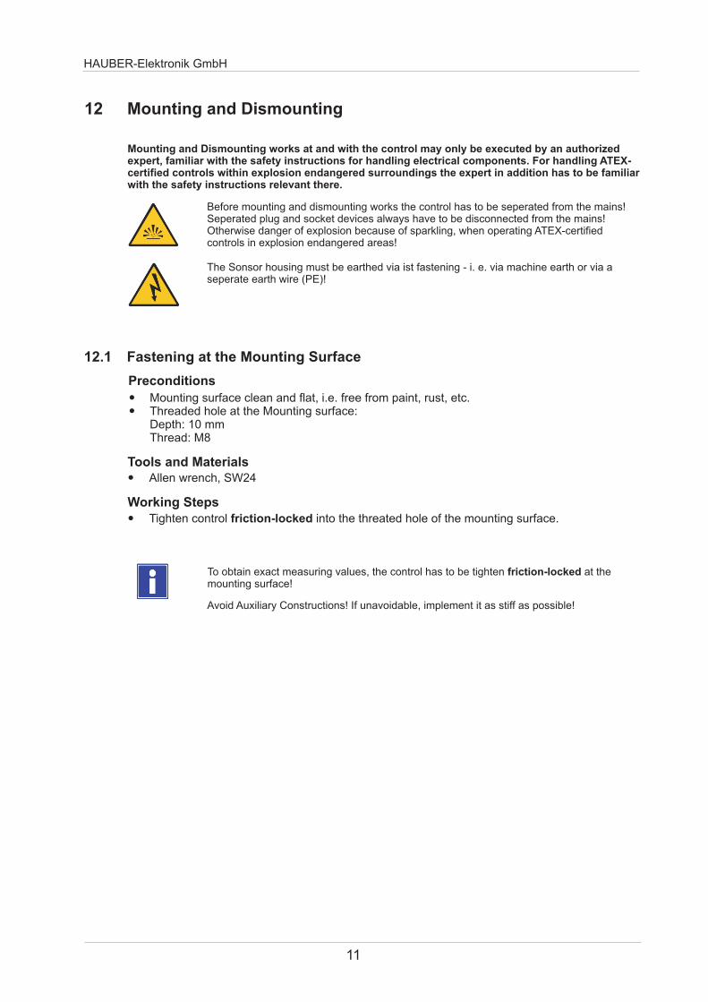

HAUBER-Elektronik GmbH
14
15 Grounding Concepts to avoid Ground Loops
Ground loops are among the most frequent problems for measurement setups with sensitive sensor technology They arise through unwanted potential differences inside the current circuit between sensor and evaluation device As countermeasure we recommend our Standard- Grounding Concept or according to application our Alternative-Grounding Concept
Alternativ-Grounding Concept
In the Alternative-Grounding Concept the shield of the sensor cable has connection to the sensor-hausing (dotted circle) The sensor hausing is decoupled from the machine ground via EMC-adapter (black)
Machine Evaluation Device
+24V 420mA
Sensor Cable
Machine
+24V 420mA
Sensor Cable
Evaluation Deviceeg AmperemeterPLC-Control
Standard-Grounding Concept
In the Standard-Grounding Concept the shield of the sensor cable has no connection to the sensor-hausing (dotted circle) The sensor housing lies on the same potential as the machine ground
Maschine ground
Maschine Ground
Sensor-Housing
EMC-Adapter
Please indicate in your order if you decide to use the Alternative-Grounding ConceptWe will then offer to you the according Sensor Cable and EMC-Adapter
Evaluation Device
Evaluation Deviceeg AmperemeterPLC-Control
Shield
ShieldSensor-Housing