Embed Size (px)
Citation preview
7/22/2019 Vibration Analysis.pdf
http://slidepdf.com/reader/full/vibration-analysispdf 1/6
Modern Mechanical Engineering, 2011, 1, 6-11doi:10.4236/mme.2011.11002 Published Online August 2011 (http://www.SciRP.org/journal/mme)
Copyright © 2011 SciRes. MME
Design Optimization of Shell and Tube Heat
Exchanger by Vibration Analysis
Shravan H. Gawande1, Appasaheb A. Keste
1, Laxman G. Navale
1, Milindkumar R. Nandgaonkar
1,
Vaishali J. Sonawane1, Umesh B. Ubarhande
2
1 Department of Mechanical Engineering, Modern Education Society’s College of Engineering, Pune, India
2PEM Design ( R&D), Alfa Laval ( India) Ltd., Pune, India
E-mail: [email protected]
Received July 23, 2011; revised August 7, 2011; accepted August 15, 2011
Abstract
In this paper a simplified approach to optimize the design of Shell Tube Heat Exchanger [STHE] by flow
induced vibration analysis [FVA] is presented. The vibration analysis of STHE helps in achieving optimiza-tion in design by prevention of tube failure caused due to flow induced vibration. The main reason for tube
failure due to flow induced vibration is increased size of STHE. It is found that in case of increased size of
STHE, the surface area and number of tubes increases, thus the understanding and analysis of vibration be-
comes a very difficult task. Again it is found that flow induced vibration analysis is considered as an integral
part of mechanical & thermal design of STHE. The detailed design, fabrication, testing and analysis work
was carried out at Alfa Laval (India), Ltd., Pune-10.
Keywords: Heat Exchanger, Flow-Induced Vibration, TEMA, HTRI
1. Introduction
The principal culprit in flow induced vibration of tubes
of STHE is the unsupported tube lengths subjected to
large flow rates on shell side. The increased size of
STHE due to large flow rates is responsible for vibration
of tubes, which further leads to tube failure. Also the
design of STHE is made safer by modifying shell type
and/or baffles style and baffle design. Thus, the vibration
analysis is of utmost importance in design of STHE. So,
the flow induced vibration analysis is considered as an
integral part of thermal design.
The characteristics of vortex shedding from tube banks
with closely mounted serrated fin was investigated in [1]
where the relationship between the Strouhal number de-fined by the equivalent diameter as the characteristic
length of a finned tube in the tube banks and the Strouhal
number map for bare-tube banks was examined. Whereas
in [2] the author has presented various outlet conditions
of a shell and tube heat exchanger theoretically and ex-
perimentally in which it is observed that prime parameter
geometry of outlet affects the performance, maintenance
and life span of a vertical shell and tube evaporator. The
heat transfer enhancement has been achieved in [3], by
modifying the configuration of a shell-and-tube heat ex-
changer, through the installation of sealers in the shell-
side. The gaps between the baffle plates and shell is
blocked by the sealers, which effectively decreases the
short-circuit flow in the shell-side. The original short-
circuit flow then participates in heat transfer, which in-
tensifies the heat transfer performance inside the heat
exchanger. The use of a non-traditional optimization tech-
nique; called Particle Swarm Optimization (PSO), for
design optimization of shell-and-tube heat exchangers
from economic view point is explored in [4] in which
minimization of total annual cost is considered as an ob-
jective function. Three design variables such as shell
internal diameter, outer tube diameter and baffle spacing
are considered for optimization. Two tube layouts viz.
triangle and square are also considered for optimization.The results of optimization using PSO technique are
compared with those obtained by using Genetic Algo-
rithm (GA). Also the optimization of the design of shell-
and-tube heat exchangers by minimization of the thermal
surface of the equipment, for certain minimum excess
area and maximum pressure drops, considering discrete
decision variables is presented in [5]. The heat transfer
coefficient and pressure drop on the shell side of a
shell-and-tube heat exchanger has been obtained experi-
mentally in [6] for three different types of copper tubes.
7/22/2019 Vibration Analysis.pdf
http://slidepdf.com/reader/full/vibration-analysispdf 2/6
S. H. GAWANDE ET AL.
Copyright © 2011 SciRes. MME
7
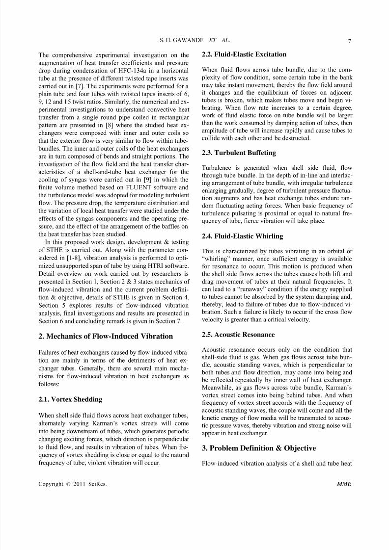
The comprehensive experimental investigation on the
augmentation of heat transfer coefficients and pressure
drop during condensation of HFC-134a in a horizontal
tube at the presence of different twisted tape inserts was
carried out in [7]. The experiments were performed for a
plain tube and four tubes with twisted tapes inserts of 6,9, 12 and 15 twist ratios. Similarly, the numerical and ex-
perimental investigations to understand convective heat
transfer from a single round pipe coiled in rectangular
pattern are presented in [8] where the studied heat ex-
changers were composed with inner and outer coils so
that the exterior flow is very similar to flow within tube-
bundles. The inner and outer coils of the heat exchangers
are in turn composed of bends and straight portions. The
investigation of the flow field and the heat transfer char-
acteristics of a shell-and-tube heat exchanger for the
cooling of syngas were carried out in [9] in which the
finite volume method based on FLUENT software and
the turbulence model was adopted for modeling turbulent
flow. The pressure drop, the temperature distribution and
the variation of local heat transfer were studied under the
effects of the syngas components and the operating pre-
ssure, and the effect of the arrangement of the baffles on
the heat transfer has been studied.
In this proposed work design, development & testing
of STHE is carried out. Along with the parameter con-
sidered in [1-8], vibration analysis is performed to opti-
mized unsupported span of tube by using HTRI software.
Detail overview on work carried out by researchers is
presented in Section 1, Section 2 & 3 states mechanics of
flow-induced vibration and the current problem defini-tion & objective, details of STHE is given in Section 4.
Section 5 explores results of flow-induced vibration
analysis, final investigations and results are presented in
Section 6 and concluding remark is given in Section 7.
2. Mechanics of Flow-Induced Vibration
Failures of heat exchangers caused by flow-induced vibra-
tion are mainly in terms of the detriments of heat ex-
changer tubes. Generally, there are several main mecha-
nisms for flow-induced vibration in heat exchangers as
follows:
2.1. Vortex Shedding
When shell side fluid flows across heat exchanger tubes,
alternately varying Karman’s vortex streets will come
into being downstream of tubes, which generates periodic
changing exciting forces, which direction is perpendicular
to fluid flow, and results in vibration of tubes. When fre-
quency of vortex shedding is close or equal to the natural
frequency of tube, violent vibration will occur.
2.2. Fluid-Elastic Excitation
When fluid flows across tube bundle, due to the com-
plexity of flow condition, some certain tube in the bank
may take instant movement, thereby the flow field around
it changes and the equilibrium of forces on adjacent
tubes is broken, which makes tubes move and begin vi-
brating. When flow rate increases to a certain degree,
work of fluid elastic force on tube bundle will be larger
than the work consumed by damping action of tubes, then
amplitude of tube will increase rapidly and cause tubes to
collide with each other and be destructed.
2.3. Turbulent Buffeting
Turbulence is generated when shell side fluid, flow
through tube bundle. In the depth of in-line and interlac-
ing arrangement of tube bundle, with irregular turbulence
enlarging gradually, degree of turbulent pressure fluctua-tion augments and has heat exchange tubes endure ran-
dom fluctuating acting forces. When basic frequency of
turbulence pulsating is proximal or equal to natural fre-
quency of tube, fierce vibration will take place.
2.4. Fluid-Elastic Whirling
This is characterized by tubes vibrating in an orbital or
“whirling” manner, once sufficient energy is available
for resonance to occur. This motion is produced when
the shell side flows across the tubes causes both lift and
drag movement of tubes at their natural frequencies. It
can lead to a “runaway” condition if the energy supplied to tubes cannot be absorbed by the system damping and,
thereby, lead to failure of tubes due to flow-induced vi-
bration. Such a failure is likely to occur if the cross flow
velocity is greater than a critical velocity.
2.5. Acoustic Resonance
Acoustic resonance occurs only on the condition that
shell-side fluid is gas. When gas flows across tube bun-
dle, acoustic standing waves, which is perpendicular to
both tubes and flow direction, may come into being and
be reflected repeatedly by inner wall of heat exchanger.
Meanwhile, as gas flows across tube bundle, Karman’svortex street comes into being behind tubes. And when
frequency of vortex street accords with the frequency of
acoustic standing waves, the couple will come and all the
kinetic energy of flow media will be transmuted to acous-
tic pressure waves, thereby vibration and strong noise will
appear in heat exchanger.
3. Problem Definition & Objective
Flow-induced vibration analysis of a shell and tube heat

7/22/2019 Vibration Analysis.pdf
http://slidepdf.com/reader/full/vibration-analysispdf 3/6
S. H. GAWANDE ET AL.
Copyright © 2011 SciRes. MME
8
exchanger is an integral element of its thermal design. A
proper design is one that is absolutely safe against failure
of tubes due to flow induced vibration. Most sophisti-
cated thermal design software packages carry out vibra-
tion analysis as a routine ingredient of thermal design.
This is essential since it is during thermal design that the
geometry of a heat exchanger is finalized and it is thissame geometry, along with flow, physical and property
parameters, determines whether the given heat exchanger is safe against failure of tubes due to flow-induced vibra-
tions. Flow-induced vibration is a very complex subject
and involves the interplay of several parameters, many of
which are not very well established. Although many cases
of failure of tubes due to flow-induced vibration has been
reported in the past several years, and an understanding of
the factors responsible for these failures leave much to be
desired. The literature depicts several interesting studies
on specific facets of the vibration problem; however, very
few investigations have considered the specific problemsassociated with shell and tube heat exchangers.
Hence in order to provide a simple solution to above
stated problem, in this work Flow-induced Vibration
Analysis of a STHE is performed to optimize the design
Parameter. It is found that the FVA of STHE helps in
achieving optimization in design of STHE by prevention
of tube failure caused due to flow induced vibration.
4. Shell and Tube Heat ExchangerSpecification
The details of STHE are shown in Table 1.
Figure 1 shows the STHE under consideration duringmanufacturing phase with all parts.
Table 1. STHE Specification.
Parameter Description
Size (Dia./length) Ø1336/10000 mm
Surface area (eff.)/unit 781.4 m. sq.
Shells/unit 1
Heat Exchanged, (Q) 5064.9 KWLMTD (Corrected) 9.15 C̊
Figure 1. Shell and Tube Heat Exchanger.
5. Flow-Induced Vibration Analysis [FVA]
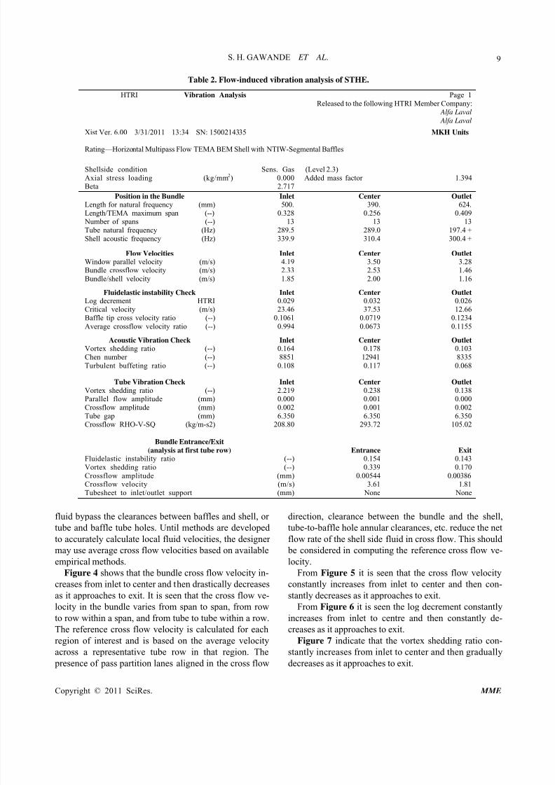
Table 2 shows the Flow-Induced Vibration AnalysisResults of STHE by using HTRI software.
6. Results & Discussion
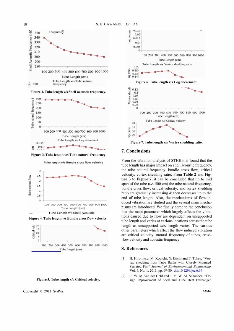
From Figure 2, it is observed that the bundle shell acous-
tic frequency decreases from inlet to exit, hence the na-
ture of the plot is parabolic. Acoustic resonance is due to
gas column oscillation and is excited by phased vortex
shedding. The oscillation creates an acoustic vibration of
a standing wave type. The generated sound wave will not
affect the tube bundle unless the acoustic resonant fre-
quency approaches the tube natural frequency, although
the heat exchanger shell and the attached piping may
vibrate, accompanied with loud noise. Then the acoustic
resonant frequency approaches the tube natural fre-
quency, any tendency toward tube vibration will be ac-centuated with possible tube failure.
There are several means available to correct a resonant
condition, but most could have some effect on exchanger
performance. The simplest method is to install dereso-
nating baffle(s) in the exchanger bundle to break the
wave(s) at or near the antinode (This can be done with-
out significantly affecting the shell side flow pattern. In
shell and tube exchangers, the standing wave forms are
limited to the first or the second mode. Failure to check
both modes can result in acoustic resonance, even with
deresonating baffles.
From Figure 3, it is observed that the tube natural fre-quency almost remains constant from inlet to center and
then drastically decreases as it approaches to exit. From
analysis it is observed that the individual unsupported
span natural frequency is affected by tube elastic and
inertial properties, tube geometry, span shape, the type of
support at each end of the unsupported span and axial
loading on the tube unsupported span. Most heat ex-
changers have multiple baffle supports and varied indi-
vidual unsupported spans. Calculation of the natural fre-
quency of the heat exchanger tube is an essential step in
estimating its potential for flow induced vibration failure.
The current state-of-the-art flow induced vibration cor-
relations are not sophisticated enough to warrant treatingthe multi-span tube vibration problem (or mode shapes
other than the fundamental) in one comprehensive analy-
sis. Therefore, the potential for vibration is evaluated for
each individual unsupported span, with the velocity and
natural frequency considered being that of the unsup-
ported span under examination.
One of the most important and least predictable pa-
rameters of flow induced vibration is fluid velocity. To
calculate the local fluid velocity at a particular point in
the heat exchanger is a difficult task. Various amounts of
7/22/2019 Vibration Analysis.pdf
http://slidepdf.com/reader/full/vibration-analysispdf 4/6
S. H. GAWANDE ET AL.
Copyright © 2011 SciRes. MME
9
Table 2. Flow-induced vibration analysis of STHE.
HTRI Vibration Analysis Page 1
Released to the following HTRI Member Company: Alfa Laval
Alfa Laval
Xist Ver. 6.00 3/31/2011 13:34 SN: 1500214335 MKH Units
Rating—Horizontal Multipass Flow TEMA BEM Shell with NTIW-Segmental Baffles
Shellside condition Sens. Gas
Axial stress loading (kg/mm2) 0.000Beta 2.717
(Level 2.3)
Added mass factor 1.394
Position in the Bundle
Length for natural frequency (mm)
Length/TEMA maximum span (--) Number of spans (--)
Tube natural frequency (Hz)
Shell acoustic frequency (Hz)
Inlet
500.
0.32813
289.5
339.9
Center
390.
0.25613
289.0
310.4
Outlet
624.
0.40913
197.4 +
300.4 +
Flow Velocities
Window parallel velocity (m/s)Bundle crossflow velocity (m/s)
Bundle/shell velocity (m/s)
Inlet
4.192.33
1.85
Center
3.502.53
2.00
Outlet
3.281.46
1.16
Fluidelastic instability Check
Log decrement HTRICritical velocity (m/s)
Baffle tip cross velocity ratio (--)
Average crossflow velocity ratio (--)
Inlet
0.02923.46
0.1061
0.994
Center
0.03237.53
0.0719
0.0673
Outlet
0.02612.66
0.1234
0.1155
Acoustic Vibration Check
Vortex shedding ratio (--)
Chen number (--)
Turbulent buffeting ratio (--)
Inlet
0.164
8851
0.108
Center
0.178
12941
0.117
Outlet
0.103
8335
0.068
Tube Vibration Check
Vortex shedding ratio (--)Parallel flow amplitude (mm)
Crossflow amplitude (mm)
Tube gap (mm)Crossflow RHO-V-SQ (kg/m-s2)
Inlet
2.2190.000
0.002
6.350208.80
Center
0.2380.001
0.001
6.350293.72
Outlet
0.1380.000
0.002
6.350105.02
Bundle Entrance/Exit
(analysis at first tube row)
Fluidelastic instability ratio (--)
Vortex shedding ratio (--)
Crossflow amplitude (mm)Crossflow velocity (m/s)
Tubesheet to inlet/outlet support (mm)
Entrance
0.154
0.339
0.005443.61
None
Exit
0.143
0.170
0.003861.81
None
fluid bypass the clearances between baffles and shell, or
tube and baffle tube holes. Until methods are developed
to accurately calculate local fluid velocities, the designer
may use average cross flow velocities based on availableempirical methods.
Figure 4 shows that the bundle cross flow velocity in-
creases from inlet to center and then drastically decreases
as it approaches to exit. It is seen that the cross flow ve-
locity in the bundle varies from span to span, from row
to row within a span, and from tube to tube within a row.
The reference cross flow velocity is calculated for each
region of interest and is based on the average velocity
across a representative tube row in that region. The
presence of pass partition lanes aligned in the cross flow
direction, clearance between the bundle and the shell,
tube-to-baffle hole annular clearances, etc. reduce the net
flow rate of the shell side fluid in cross flow. This should
be considered in computing the reference cross flow ve-locity.
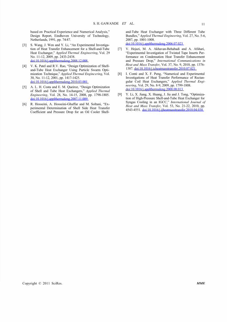
From Figure 5 it is seen that the cross flow velocity
constantly increases from inlet to center and then con-
stantly decreases as it approaches to exit.
From Figure 6 it is seen the log decrement constantly
increases from inlet to centre and then constantly de-
creases as it approaches to exit.
Figure 7 indicate that the vortex shedding ratio con-
stantly increases from inlet to center and then gradually
decreases as it approaches to exit.
7/22/2019 Vibration Analysis.pdf
http://slidepdf.com/reader/full/vibration-analysispdf 5/6
S. H. GAWANDE ET AL.
Copyright © 2011 SciRes. MME
10
Figure 2. Tube length v/s Shell acoustic frequency.
Figure 3. Tube length v/s Tube natural frequency
Figure 4. Tube length v/s Bundle cross flow velocity.
Figure 5. Tube length v/s Critical velocity.
Figure 6. Tube length v/s Log decrement.
Figure 7. Tube length v/s Vortex shedding ratio.
7. Conclusions
From the vibration analysis of STHE it is found that the
tube length has major impact on shell acoustic frequency,
the tube natural frequency, bundle cross flow, critical
velocity, vortex shedding ratio. From Table 2 and Fig-ure 3 to Figure 7, it can be concluded that up to mid
span of the tube (i.e. 500 cm) the tube natural frequency,
bundle cross flow, critical velocity, and vortex shedding
ratio are gradually increasing & then decreases up to the
end of tube length. Also, the mechanisms of flow-in-
duced vibration are studied and the several main mecha-
nisms are introduced. We finally come to the conclusion
that the main parameter which largely affects the vibra-
tions caused due to flow are dependent on unsupported
tube length and varies at various locations across the tube
length as unsupported tube length varies. The various
other parameters which affect the flow induced vibrationare critical velocity, natural frequency of tubes, cross-
flow velocity and acoustic frequency.
8. References
[1] H. Hiromitsu, M. Kouichi, N. Eiichi and F. Tohru, “Vor-tex Shedding from Tube Banks with Closely Mounted
Serrated Fin,” Journal of Environmentand Engineering,Vol. 6, No. 1, 2011, pp. 69-80. doi:10.1299/jee.6.69
[2] C. W. M. van der Geld and J. M. W. M. Schoonen, “De-sign Improvement of Shell and Tube Heat Exchanger
7/22/2019 Vibration Analysis.pdf
http://slidepdf.com/reader/full/vibration-analysispdf 6/6
S. H. GAWANDE ET AL.
Copyright © 2011 SciRes. MME
11
based on Practical Experience and Numerical Analysis,”
Design Report, Eindhoven University of Technology, Netherlands, 1991, pp. 74-87.
[3] S. Wang, J. Wen and Y. Li, “An Experimental Investiga-tion of Heat Transfer Enhancement for a Shell-and-Tube
Heat Exchanger,” Applied Thermal Engineering, Vol. 29
No. 11-12, 2009, pp. 2433-2438.doi:10.1016/j.applthermaleng.2008.12.008
[4] V. K. Patel and R.V. Rao, “Design Optimization of Shell-
and-Tube Heat Exchanger Using Particle Swarm Opti-mization Technique,” Applied Thermal Engineering, Vol.30, No. 11-12, 2001, pp. 1417-1425.
doi:10.1016/j.applthermaleng.2010.03.001
[5] A. L. H. Costa and E. M. Queiroz, “Design Optimization
of Shell and Tube Heat Exchangers,” Applied Thermal
Engineering, Vol. 28, No. 14-15, 2008, pp. 1798-1805.
doi:10.1016/j.applthermaleng.2007.11.009
[6] R. Hosseini, A. Hosseini-Ghaffar and M. Soltani, “Ex-
perimental Determination of Shell Side Heat Transfer
Coefficient and Pressure Drop for an Oil Cooler Shell-
and-Tube Heat Exchanger with Three Different Tube
Bundles,” Applied Thermal Engineering, Vol. 27, No. 5-6,2007, pp. 1001-1008.
doi:10.1016/j.applthermaleng.2006.07.023
[7] V. Hejazi, M. A. Akhavan-Behabadi and A. Afshari,
“Experimental Investigation of Twisted Tape Inserts Per-
formance on Condensation Heat Transfer Enhancementand Pressure Drop,” International Communications in
Heat and Mass Transfer , Vol. 37, No. 9, 2010, pp. 1376-1387. doi:10.1016/j.icheatmasstransfer.2010.07.021
[8] I. Conté and X. F. Peng, “Numerical and ExperimentalInvestigations of Heat Transfer Performance of Rectan-gular Coil Heat Exchangers,” Applied Thermal Engi-
neering, Vol. 29, No. 8-9, 2009, pp. 1799-1808.doi:10.1016/j.applthermaleng.2008.08.013
[9] Y. Li, X. Jiang, X. Huang, J. Jia and J. Tong, “Optimiza-tion of High-Pressure Shell-and-Tube Heat Exchanger for Syngas Cooling in an IGCC,” International Journal of
Heat and Mass Transfer , Vol. 53, No. 21-22, 2010, pp.4543-4551. doi:10.1016/j.ijheatmasstransfer.2010.04.038