Embed Size (px)
Citation preview

Verigy V93000Service Training
Compact Test Head

Compact Test HeadPage 2
Compact Test HeadManufacturing Manipulator
Manipulator E6979LC
LINUX Controller
Flat Panel Holder
E6979LF
Compact Test Head E8014A
DUT-Interface with Hard Docking E8009L

Compact Test HeadPage 3
Compact Test Head Engineering Manipulator
Engineering Manipulator E6979EC
Compact Test Head E8014A
DUT-Interface without Hard Docking E8009LD
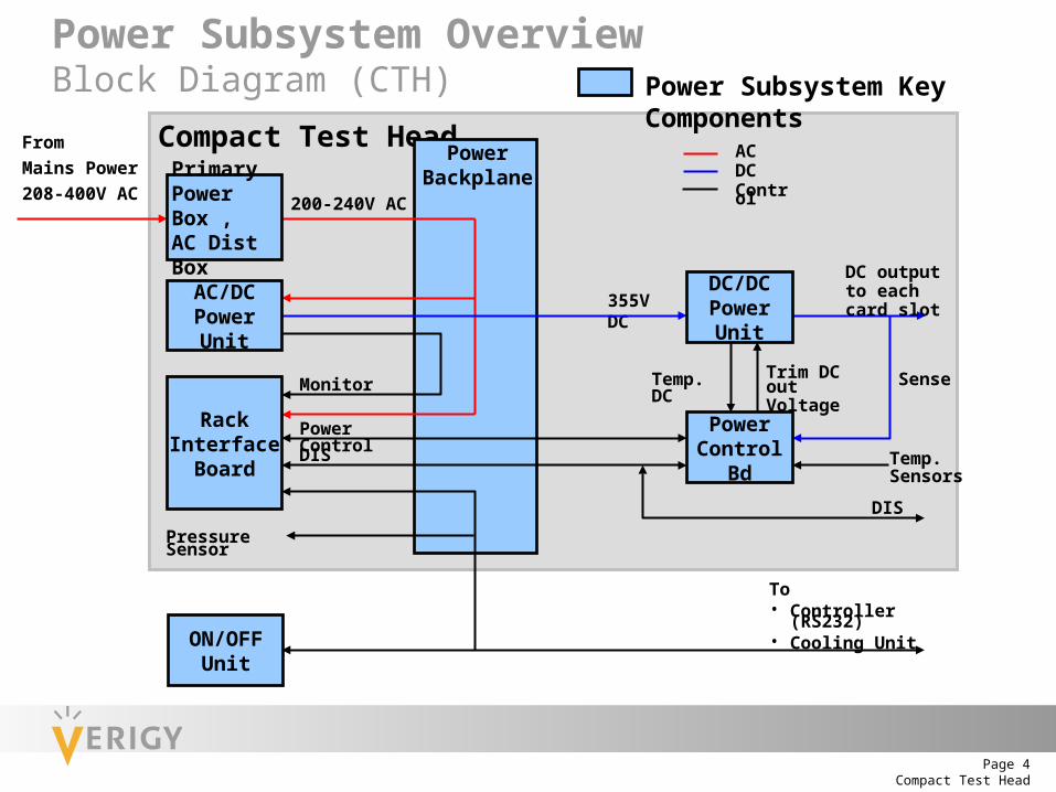
Compact Test HeadPage 4
Compact Test HeadPower
Backplane
355V DC
Trim DC out Voltage
200-240V AC
To• Controller (RS232)• Cooling Unit
Pressure Sensor
DIS
Temp.Sensors
Sense
DC output to each card slot
Temp. DCMonitor
DIS
Power Control
From
Mains Power
208-400V AC
ACDCControlPrimary
Power Box ,AC Dist Box
AC/DC Power Unit
Rack Interface
Board
ON/OFF Unit
DC/DC Power Unit
Power Control Bd
Power Subsystem Key Components
Power Subsystem OverviewBlock Diagram (CTH)

Compact Test HeadPage 5
Primary Power Distribution CTHStar 400V/230V
Pow er D istribution U nit (star connection for 400V /230V)
T1
T2
T3
L1
L2
L3S1 K1
S2 AC /D C #1
S3
L2/N
L3/N AC /D C #2
S4 O utle t
PE
F1
F2L1/N
N
PE
Line
F3
F4
Filter
T1/N
R ack In terfaceBoard
N
N
N
L1
L2
L3

Compact Test HeadPage 6
Primary Power Distribution CTHDelta 200V-208V
T1
T2
T3
L1
L2
L3S1 K1
S2 AC/D C #1
S3
L2/N
L3/N AC/D C #2
S4 O utlet
PE
F1
F2L1/N
N
PE
Line
F3
F4
Filter
T1/N
R ack In terfaceBoard
N
N
N
L1
L2
L3
Pow er D istribution Unit (delta connection for 200V/115V)

Compact Test HeadPage 7
Compact Test Head Power Connections
Mains power inlet
Mains power out(Cal Robot)
Main breaker

Compact Test HeadPage 8
Compact Test Head Connections
Mains power inlet
Optical link
Cooling water in
Cooling water out
Compressed air
Mains power out(Cal Robot)
Main breaker
Low Level Diagnostic Cable RS232
Cooler Control
ON/OFF Unit cable

Compact Test HeadPage 9
Connecting Mains Power 1
Remove main breaker cover
1. Release three screws
2. Lift off cover

Compact Test HeadPage 10
Connecting Mains Power 2
2. Lift off cover
Remove cable clamp cover
1. Remove four screws
3. Select cover according to cable diameter

Compact Test HeadPage 11
Mains Power Terminals
Phase terminals L1
L2L3
N terminal(Star config. only)
PE terminal

Compact Test HeadPage 12
Main Breaker Settings
Instantaneous trip multiple Current Selector
Star 400V 50ADelta 208V 55ADelta 200V 60A
All configurations: 6

Compact Test HeadPage 13
Compact Test Head Bottom/Maintenance Side
Active Control BoardCC 1
Passive Control BoardCC2
Rack Interface Board
Jumper Board
Optical link
AC/DC Power Units
On/Off Unit AC/DC Power Box

Compact Test HeadPage 14
Compact Test Head DUT-Side (DUT-Interface and Covers removed)
Power Backplane
Front Plane CC1
Power Control Board 11
Front Plane CC2
Power Control Board 12
Power Control Cable 2
Power Control Cable 1

Compact Test HeadPage 15
Use the hose extraction tool for the cooling hoses
Weight : 15kg
AC/DC Power Unit – Exchange
Compact Test HeadPage 16
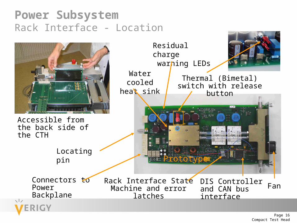
Rack Interface State Machine and error latches
Residual charge warning LEDs
Thermal (Bimetal) switch with release button
Connectors to Power Backplane
Locating pin
DIS Controller and CAN bus interface
Accessible from the back side of the CTH
Power SubsystemRack Interface - Location
Fan
Water cooled heat sink
Prototype

Compact Test HeadPage 17
Hard Docking Interface
The Hard Docking interface must be removed for the exchange of:
• DUT Interface / Wiring Board
• Power Control Boards
• Frontplanes
• Power Backplane
• DC/DC Fuses

Compact Test HeadPage 18
DUT-Interface
DPS cables
Wiring Board
To remove the DUT Interface:
• remove cards from card cages
• disconnect soft docking air tubes
• remove 12 countersink screws
• two persons are needed!
Utility adapter board
Space for Pogo Cable Assys

Compact Test HeadPage 19
Breakers and Fuses
Exchanging a DC/DC fuse
Exchanging a breaker Exchanging an AC fuse

Compact Test HeadPage 20
Power Backplane
Cooler Control RS232 for low level diagnostic
ON/OFF Unit with EMO
Rack Interface Board Connectors
AC/DC Power Unit Connectors

Compact Test HeadPage 21
Power Backplane LEDs
Remove cover to check LEDs

Compact Test HeadPage 22
Power Backplane Exchange
1. Remove covers 2. Remove PE wires 3. Remove connectors
6. Lift off Power Backplane4. Remove stiffener rails 5. Disconnect cables
Compact Test HeadPage 23
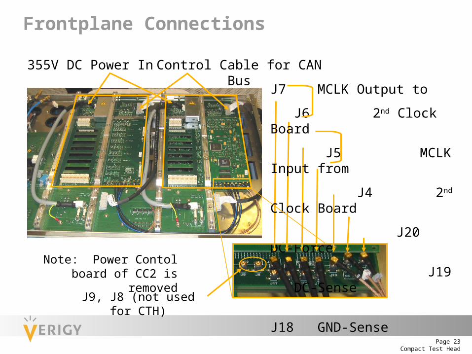
Frontplane Connections
355V DC Power In Control Cable for CAN Bus
J7 MCLK Output to
J6 2nd Clock Board
J5 MCLK Input from
J4 2nd Clock Board
J20 DC-Force
J19 DC-Sense
J18 GND-Sense
J9, J8 (not used for CTH)
Note: Power Contol board of CC2 is removed

Compact Test HeadPage 24
RS232 and CAN Bus System
Rack interfaceboard
RS232cable
Clockboard
Active controlboard
Card Cage 2 Card Cage 1
Powercontrol board
CTH
Systemcontroller
Power backplane
To M
anip
ulat
orPowercontrol board
Termination
Con
trol
Cab
le 2
Con
trol
Cab
le 1
Wiring Board

Compact Test HeadPage 25
Changes with Compact Test Head
STH and LTH
1 Card Cage for 1 Group
Why 2 terms for the same?
Filling starts with slot 101
PinScale filling with gaps
Slot - Pogo mapping fixed
CTH
1 Card Cage for 2 Groups
Group # compatible for CTH, STH, LTH
Filling starts with slot 105
Filling of cards in pairs
Slot - Pogo mapping is flexible
and defined by Pogo Mapping file

Compact Test HeadPage 26
Compact Test Head Pogo Mapping
Test Head Cable Outlet
DPS 8 Util. 4 DPS 2 Util. 3
DPS 3Util. 1 DPS 1Util. 2
CC 1 Group 3 Group 1
432 S2232 S1
431 S2231 S1
430 S2230 S1
429 S2229 S1
428 S2228 S1
427 S2227 S1
426 S2226 S1
425 S2225 S1
316 S2116 S1
315 S2115 S1
314 S2114 S1
313 S2113 S1
312 S2112 S1
311 S2111 S1
310 S2110 S1
309 S2109 S1
118 S1
117 S1317 S2
318 S2
119 S1319 S2
120 S1320 S2
121 S1321 S2
122 S1322 S2
123 S1323 S2
124 S1324 S2
102 S1
101 S1301 S2
302 S2
103 S1303 S2
104 S1304 S2
105 S1305 S2
106 S1306 S2
107 S1307 S2
108 S1308 S2
CC2 Group 8 Group 2
• Up to 512 digital pins with PinScale 800 / 3600 at S1 Pogo locations
• PinScale 400 fill S1/S2 Pogo locations up to 1024 dig. pins
• Pogo location numbers and Group numbers are identical to STH
• 1 Card Cage for 2 Groups
Compact Test HeadPage 27
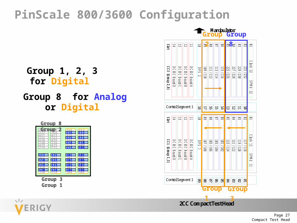
PinScale 800/3600 Configuration
Group 8 for Analog or Digital
Group 1, 2, 3 for Digital
Manipulator
2CC Compact Test Head
10 DPS 109 107 / 10808 105 / 106
01 Clock 11 SPMU 11
11 DC/DC Board A
07 103 / 104
05 123 / 124
03 119 / 120
06 101 / 102
04 121 / 122
02 117 / 118
Slot CC1 (Group 1, 3)
12 DC/DC Board B13 DC/DC Board C14 DC/DC Board D
Control Segment 1
01020304050607080910 DPS 209 109 / 11008 111 / 112
01 Clock 12 SPMU 12
11 DC/DC Board A
07 113 / 114
05 225 / 226
03 229 / 230
06 115 / 116
04 227 / 228
02 231 / 232
Slot CC3 (Group 2, 8)
12 DC/DC Board B13 DC/DC Board C14 DC/DC Board D
Control Segment 1
101112131415161718
Group 3 Group 1
Group 2 Group 8
317
232
231
230
229
432
429
430
431228
227
226
225
428
427
426
425
318
319
320
321
322
323
324
301
302
303
304
305
306
307
308
316
315
314
313
312
311
310
309
117
118
119
120
101
104
103
102
105
106
107
108
116
115
114
113
112
111
110
109
121
122
123
124
Group 3 Group 1
Group 8 Group 2

Compact Test HeadPage 28
PinScale 800/3600 Configurationwith Analog
101102
5678
1234
117118
5678
121122
1234
4321
110109
8765
4321
8765
Analog 1st PS3600 card, slot 1-5, 101-102, Pos: 105
2nd PS3600 card, slot 1-6, 103-104, Pos: 106
103104
3rd PS3600 card, slot 1-7, 105-106, Pos: 107
4th PS3600 card, slot 1-8, 107-108, Pos: 108
107108
5th PS3600 card, slot 2-8, 109-110, Pos: 117
6th PS3600 card, slot 2-7, 111-112, Pos: 116
7th PS3600 card, slot 2-6, 113-114, Pos: 115
8th PS3600 card, slot 2-5, 115-116, Pos: 114105106
112111
116115
123124
119120
Pos is the physical position in the 1st column of the pogo mapping file !
9th PS3600 card, slot 1-1, 117-118, Pos: 101
10thPS3600 card, slot 1-2, 119-120, Pos: 102
11thPS3600 card, slot 1-3, 121-122, Pos: 103
12thPS3600 card, slot 1-4, 123-124, Pos: 104
114113

Compact Test HeadPage 29
101102103104
5678
305306307308
105106107108
1234
301302303304
SLO
T 1
(SLO
T 2
)
SLO
T 3
(SLO
T 4
)
SLO
T 5
(SLO
T 6
)
SLO
T 7
(SLO
T 8
)
CLO
CK
DIS
T / S
PM
U /
UTIL
DPS
DC
PS
slot 1
,2
DC
PS
slot 3
,4
DC
PS
slot 5
,6
DC
PS
slot 7
,8
TEST HEADCABLE OUTLET SIDE
Group 8 Group 2
Group 1Group 3101102103104
105106107108
117118119120
121122123124
116115114113
232231230229
228227226225
1234
5678
1234
5678
4321
8765
4321
8765
Cage 1(slot 1-4)
Cage 2(slot 5-8)
Cage 1(slot 5-8)
Cage 2(slot 1-4)
312311310309
316315314313
112111110109
305306307308
301302303304
321322323324
317318319320
Cage 1
TEST HEADCABLE OUTLET SIDE
Cage 2
117118119120
5678
321322323324
121122123124
1234
317318319320
Cage 1
Group 3 Group 1
Group 2
116115114113
4321
312311310309
112111110109
8765
316315314313
SLO
T 1
(SLO
T 2
)
SLO
T 3
(SLO
T 4
)
SLO
T 5
(SLO
T 6
)
SLO
T 7
(SLO
T 8
)
CLO
CK
DIS
T / S
PM
U /
UTIL
DPS
DC
PS
slot 1
,2
DC
PS
slot 3
,4
DC
PS
slot 5
,6
DC
PS
slot 7
,8
Group 8232231230229
4321
428427426425
228227226225
8765
432431430429
Cage 2
PinScale 400 Configurationwith Analog

Compact Test HeadPage 30
Manipulator
2CC Compact Test Head
10 DPS 109 305 / 306 / 307 / 30808 301 / 302 / 303 / 304
01 Clock 11 SPMU 11
11 DC/DC Board A
07 105 / 106 / 107 / 108
05 321 / 322 / 323 / 324
03 121 / 122 / 123 / 124
06 101 / 102 / 103 / 104
04 317 / 318 / 319 / 320
02 117 / 118 / 119 / 120
Slot CC1 (Group 1, 3)
12 DC/DC Board B13 DC/DC Board C14 DC/DC Board D
Control Segment 1
01020304050607080910 DPS 209 109 / 110 / 111 / 11208 113 / 114 / 115 / 116
01 Clock 12 SPMU 12
11 DC/DC Board A
07 309 / 310 / 311 / 312
05 225 / 226 / 227 / 228
03 425 / 426 / 427 / 428
06 313 / 314 / 315 / 316
04 229 / 230 / 231 / 232
02 429 / 430 / 431 / 432
Slot CC3 (Group 2, 8)
12 DC/DC Board B13 DC/DC Board C14 DC/DC Board D
Control Segment 1
101112131415161718
PinScale 400 Configuration
Group 8 for Analog or Digital
Group 3 Group 1
Group 2 Group 8
Group 1, 2, 3 for Digital
232
231
230
229
432
429
430
431228
227
226
225
428
427
426
425
116
115
114
113
112
111
110
109
117
118
119
120
101
104
103
102
105
106
107
108
121
122
123
124
Group 3 Group 1
Group 8 Group 2
308
317
318
320
321
322
323
324
301
302
303
304
305
306
307319
316
315
314
313
312
311
310
309

Compact Test HeadPage 31
317
232
231
230
229
432
429
430
431228
227
226
225
428
427
426
425
318
319
320
321
322
323
324
301
302
303
304
305
306
307
308
316
315
314
313
312
311
310
309
117
118
119
120
101
104
103
102
105
106
107
108
116
115
114
113
112
111
110
109
121
122
123
124
Group 3 Group 1
Group 8 Group 2
Pogo Filling
Up to 384 pins, S1 onlyGroup 1 2 3
PinScale 400 Configuration with Analog
Card/Cage Filling – Test Head Bottom View 30
5/30
6/30
7/30
8
321/
322/
323/
324
To Manipulator
START
117/
118/
119/
120
317/
318/
319/
320
101/
102/
103/
104
301/
302/
303/
304
Gro
up 2
,8 (C
age
2)
Ana
log
Ana
log
313/
314/
315/
316
Ana
log
109/
110/
111/
112
309/
310/
311/
312
Ana
log
Gro
up 1
,3 (C
age
1)
121/
122/
123/
124
105/
106/
107/
108
113/
114/
115/
116

Compact Test HeadPage 32
Pogo Filling
Up to 768 pins, S1 and S2Group 1 2 3 3 2 1
PinScale 400 Configuration with Analog
Card/Cage Filling – Test Head Bottom View 30
5/30
6/30
7/30
8
321/
322/
323/
324
To Manipulator
Continue
117/
118/
119/
120
317/
318/
319/
320
101/
102/
103/
104
301/
302/
303/
304
Gro
up 2
,8 (C
age
2)
Ana
log
Ana
log
313/
314/
315/
316
Ana
log
109/
110/
111/
112
309/
310/
311/
312
Ana
log
Gro
up 1
,3 (C
age
1)
121/
122/
123/
124
105/
106/
107/
108
113/
114/
115/
116
232
231
230
229
432
429
430
431228
227
226
225
428
427
426
425
116
115
114
113
112
111
110
109
117
118
119
120
101
104
103
102
105
106
107
108
121
122
123
124
Group 3 Group 1
Group 8 Group 2
308
317
318
320
321
322
323
324
301
302
303
304
305
306
307319
316
315
314
313
312
311
310
309

Compact Test HeadPage 33
101102103104
5678
305306307308
105106107108
1234
301302303304
117118119120
5678
321322323324
121122123124
1234
317318319320
116115114113
4321
312311310309
112111110109
8765
316315314313
232231230229
4321
428427426425
228227226225
8765
432431430429
1st DC card, slot 1-7, 301-3022nd DC card, slot 1-8, 305-3063rd DC card, slot 2-6, 309-3104th DC card, slot 2-5, 313-3145th DC card, slot 1-3, 317-3186th DC card, slot 1-4, 321-3227th DC card, slot 1-1, 319-3208th DC card, slot 1-2, 323-3249th DC card, slot 2-8, 311-31210th DC card, slot 2-7, 315-316
317318319320
301302
305306
316315314313
321322
323324
312311310309
Analog
9th PS400 card, slot 2-5, 313-316, Pos 11410th PS400 card, slot 2-6, 309-312, Pos 11511th PS400 card, slot 1-8, 305-308, Pos 10812th PS400 card, slot 1-7, 301-304, Pos 107
1st PS400 card, slot 1-5, 101-104, Pos 1052nd PS400 card, slot 1-6, 105-108, Pos 1063rd PS400 card, slot 2-8, 109-112, Pos 1174th PS400 card, slot 2-7, 113-116, Pos 1165th PS400 card, slot 1-1, 117-120, Pos 1016th PS400 card, slot 1-2, 121-124, Pos 1027th PS400 card, slot 1-4, 321-324, Pos 1048th PS400 card, slot 1-3, 317-320, Pos 103
1st out1st out2nd out2nd out3rd out3rd out4th out4th out5th out5th out
• Up to 768 digital channels with RF or Analog
• First 384 digital channels compatible to Ce/C/P (STH)
PinScale 400 Configurationwith Analog and DC Scale

Compact Test HeadPage 34
Pogo Mapping File
• Path: /etc/opt/hp93000/soc/pogo_mapping
• For Digital use default file: pogomapping _2CC
• For Analog / RF use:
• Non-standard Pogo Mapping Files:
• pogomapping_2CC_Analog_CONF_A
• pogomapping_2CC_Analog_CONF_B
• pogomapping_2CC_Analog_CONF_C
• pogomapping_2CC_Analog_RF
• or a customized Pogo Mapping File
• Enter Non-standard or customized Pogo Mapping Files
in the GLOBAL section of the model file as:
pogo_cabeling = <filename>

Compact Test HeadPage 35
Pogo Mapping FileDefault: pogomapping_2CC# Mapping for card cage 1 onto group 1 and 3# Cage 1 slot 1-8 are filled with Pin Scale channel cards# Cage 1 slot 1-4 may be filled with RF cards, then cells need to be edited#101 -1 117,118 117,118,119,120102 -1 119,120 121,122,123,124103 -1 121,122 317,318,319,320104 -1 123,124 321,322,323,324105 -1 101,102 101,102,103,104106 -1 103,104 105,106,107,108107 -1 105,106 301,302,303,304108 -1 107,108 305,306,307,308109 1 -1,-1 -1,-1,-1,-1## Mapping for card cage 2 onto group 2 and 8# Cage 2 slot 1-8 are filled with Pin Scale channel cards# Cage 2 slot 1-4 may be filled with RF/analog cards, then cells need to be edited#110 -1 231,232 429,430,431,432111 -1 229,230 425,426,427,428112 -1 227,228 229,230,231,232113 -1 225,226 225,226,227,228114 -1 115,116 313,314,315,316115 -1 113,114 309,310,311,312116 -1 111,112 113,114,115,116117 -1 109,110 109,110,111,112118 2 -1,-1 -1,-1,-1,-1
Cards with 1 Pogo Block (DPS1)
Cards with 2 Pogo Blocks (PS800/3600)
Cards with 4 Pogo Blocks (PS400)
-1 indicates that this type is not allowed:
In DPS Slots no cards with 2 or 4 Pogo Blocks
In Channel Slots no cards with 1 Pogo Block
Cards with 2 Pogo Blocks (PS800/3600)
Cards with 4 Pogo Blocks (PS400)
Cards with 1 Pogo Block (DPS2)
Pos = (control segment x 100) + slot

Compact Test HeadPage 36
Pogo Mapping File With Analog Configuration A# Mapping for card cage 1 onto group 1 and 3# Cage 1 slot 1-8 are filled with Pin Scale channel cards#101 -1 117,118 117,118,119,120102 -1 119,120 121,122,123,124103 -1 121,122 317,318,319,320104 -1 123,124 321,322,323,324105 -1 101,102 101,102,103,104106 -1 103,104 105,106,107,108107 -1 105,106 301,302,303,304108 -1 107,108 305,306,307,308109 1 -1,-1 -1,-1,-1,-1## Mapping for card cage 2 onto group 2 and 8# Cage 2 slot 5-8 are filled with Pin Scale channel cards# Cage 2 slot 1-4 may be filled with analog cards#110 228 228,428 -1,-1,-1,-1111 231 231,431 -1,-1,-1,-1112 230 230,430 -1,-1,-1,-1113 227 227,427 -1,-1,-1,-1114 -1 115,116 313,314,315,316115 -1 113,114 309,310,311,312116 -1 111,112 113,114,115,116117 -1 109,110 109,110,111,112118 2 -1,-1 -1,-1,-1,-1
Cards with 2 Pogo Blocks
Cards with 4 Pogo Blocks
DPS 1 with 1 Pogo Block
Analog Cards with 1 Pogo Block
Analog Cards with 2 Pogo Blocks
Cards with 2 Pogo Blocks
Cards with 4 Pogo Blocks
DPS 2 with 1 Pogo Block