Embed Size (px)
Citation preview

Belim
o Pr
ojec
t: Ne
w Y
ork
Tim
es B
uild
ing,
New
Yor
k
Valve Retrofit Installation Instructionsfor use with Electronic Actuators Effective February 2010
®

Accurately size and select your control valves in minutes with
Try it at: http://selectpro.belimo.ch/login.aspx
SelectPro™
Quality products you can rely on.View our complete product line at belimo.com.
Get It All. Get It Here.Precision • Superior functionality in products designed for today’s intelligent systems.
• Highly developed technology that allows for reduced energy consumption.
• Extended product life with added comfort and safety.
• Quality tested – built to last.
• ISO 9001 quality control.
Support• Technical support and customer service group available over 11 hours a day, Monday to Friday to provide quotes, order information, and personalized assistance.
• New services are continuously developed and introduced to keep our customers at the center of our business efforts.
• Customer needs are responded to quickly and comprehensively.
• On-time delivery.
• Onsite around the globe.
Solutions• Comprehensive actuation product line addresses all needs including rotary, linear, 360° rotation, and fi re and smoke applications.
• Innovative valve offering provides cost-effective solutions promoting energy effi ciency to complement economic and design trends.
• Simple ways to retrofi t your existing electronic or pneumatic valves and actuators.
• A variety of valves to meet the wide range of commercial applications.

800-543-9038 USA 866-805-7089 CANADA 203-791-8396 LATIN AMERICA
4
7114
8-00
001
- 02/
10 -
SUBJ
ECT
TO C
HANG
E. ©
BEL
IMO
AIRC
ONTR
OLS
(USA
), IN
C.
Assembly Sequence for Existing Valves
UGLK/UGSP Series Globe Valve Retrofit SolutionRetrofitting STYLE 1 Globe Valves Typical for Siebe\Invensys\Barber Colman
A
C
D
F
B
E
Follow these steps to properly assemble STYLE 1 type globe valves to the retrofit linkage. Reference the step-by-step photos to help guide you through the assembly process.
The valve should be stripped down to its basic form, as shown. The linkage components have been designed to attach to the valve in this state, rather than to any existing hardware. Note that this style valve has a permanently attached bonnet nut which rotates freely, but does not come off the valve itself.
STEP 1) Assemble the supplied stem nut (E) to the valve stem, and thread at least 10 - 12 turns down onto the stem.
STEP 2) Attach the rack assembly (F), which may or may not include an extension or adapter, onto the valve stem. Thread the assembly as far down onto the valve stem as possible, until you contact the previously attached valve stem nut.
800-543-9038 USA 866-805-7089 CANADA 203-791-8396 LATIN AMERICA
5
7114
8-00
001
- 02/
10 -
SUBJ
ECT
TO C
HANG
E. ©
BEL
IMO
AIRC
ONTR
OLS
(USA
), IN
C.
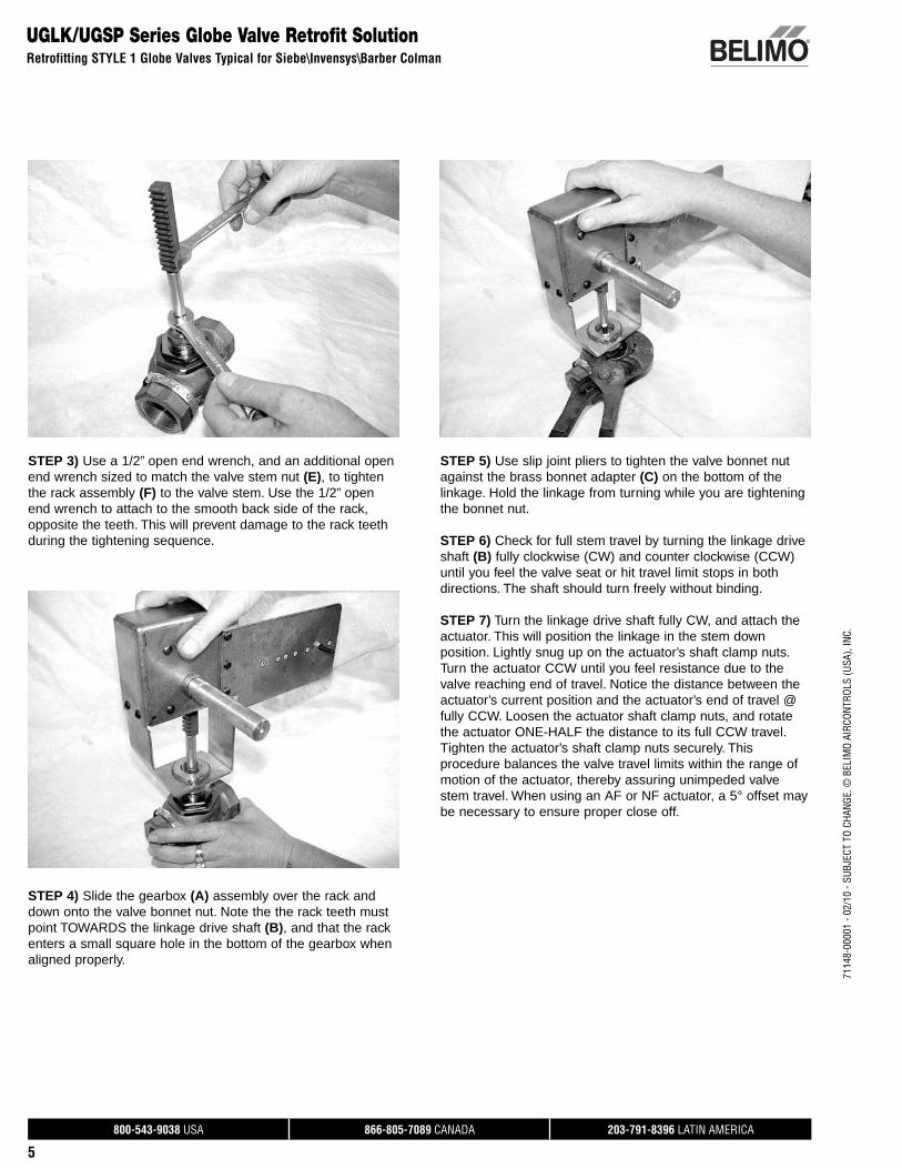
STEP 3) Use a 1/2” open end wrench, and an additional open end wrench sized to match the valve stem nut (E), to tighten the rack assembly (F) to the valve stem. Use the 1/2” open end wrench to attach to the smooth back side of the rack, opposite the teeth. This will prevent damage to the rack teeth during the tightening sequence.
STEP 4) Slide the gearbox (A) assembly over the rack and down onto the valve bonnet nut. Note the the rack teeth must point TOWARDS the linkage drive shaft (B), and that the rack enters a small square hole in the bottom of the gearbox when aligned properly.
STEP 5) Use slip joint pliers to tighten the valve bonnet nut against the brass bonnet adapter (C) on the bottom of the linkage. Hold the linkage from turning while you are tightening the bonnet nut.
STEP 6) Check for full stem travel by turning the linkage drive shaft (B) fully clockwise (CW) and counter clockwise (CCW) until you feel the valve seat or hit travel limit stops in both directions. The shaft should turn freely without binding.
STEP 7) Turn the linkage drive shaft fully CW, and attach the actuator. This will position the linkage in the stem down position. Lightly snug up on the actuator’s shaft clamp nuts. Turn the actuator CCW until you feel resistance due to the valve reaching end of travel. Notice the distance between the actuator’s current position and the actuator’s end of travel @ fully CCW. Loosen the actuator shaft clamp nuts, and rotate the actuator ONE-HALF the distance to its full CCW travel. Tighten the actuator’s shaft clamp nuts securely. This procedure balances the valve travel limits within the range of motion of the actuator, thereby assuring unimpeded valve stem travel. When using an AF or NF actuator, a 5° offset may be necessary to ensure proper close off.
UGLK/UGSP Series Globe Valve Retrofit SolutionRetrofitting STYLE 1 Globe Valves Typical for Siebe\Invensys\Barber Colman
800-543-9038 USA 866-805-7089 CANADA 203-791-8396 LATIN AMERICA
6
7114
8-00
001
- 02/
10 -
SUBJ
ECT
TO C
HANG
E. ©
BEL
IMO
AIRC
ONTR
OLS
(USA
), IN
C.
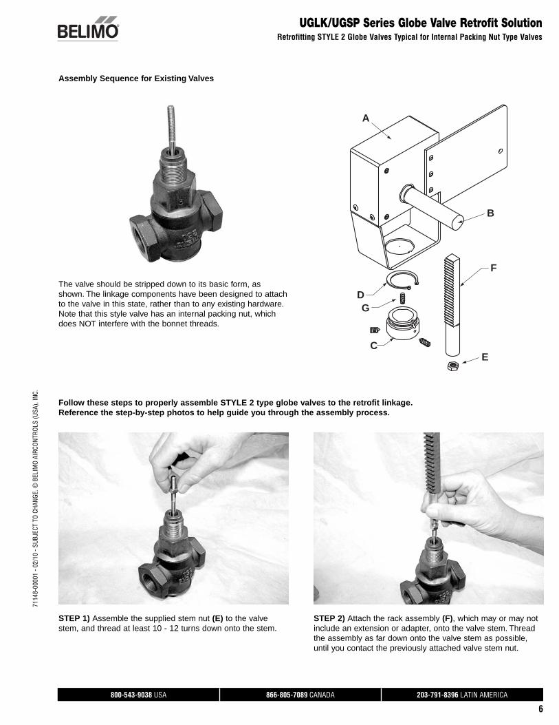
UGLK/UGSP Series Globe Valve Retrofit SolutionRetrofitting STYLE 2 Globe Valves Typical for Internal Packing Nut Type Valves
Assembly Sequence for Existing Valves
Follow these steps to properly assemble STYLE 2 type globe valves to the retrofit linkage. Reference the step-by-step photos to help guide you through the assembly process.
STEP 1) Assemble the supplied stem nut (E) to the valve stem, and thread at least 10 - 12 turns down onto the stem.
STEP 2) Attach the rack assembly (F), which may or may not include an extension or adapter, onto the valve stem. Thread the assembly as far down onto the valve stem as possible, until you contact the previously attached valve stem nut.
The valve should be stripped down to its basic form, as shown. The linkage components have been designed to attach to the valve in this state, rather than to any existing hardware. Note that this style valve has an internal packing nut, which does NOT interfere with the bonnet threads.
A
C
D
F
B
E
G
800-543-9038 USA 866-805-7089 CANADA 203-791-8396 LATIN AMERICA
7
7114
8-00
001
- 02/
10 -
SUBJ
ECT
TO C
HANG
E. ©
BEL
IMO
AIRC
ONTR
OLS
(USA
), IN
C.
UGLK/UGSP Series Globe Valve Retrofit SolutionRetrofitting STYLE 2 Globe Valves Typical for Internal Packing Nut Type Valves
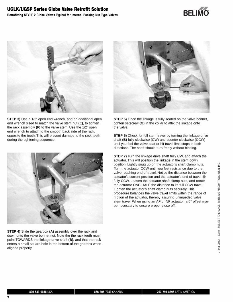
STEP 3) Use a 1/2” open end wrench, and an additional open end wrench sized to match the valve stem nut (E), to tighten the rack assembly (F) to the valve stem. Use the 1/2” open end wrench to attach to the smooth back side of the rack, opposite the teeth. This will prevent damage to the rack teeth during the tightening sequence.
STEP 4) Slide the gearbox (A) assembly over the rack and down onto the valve bonnet nut. Note the the rack teeth must point TOWARDS the linkage drive shaft (B), and that the rack enters a small square hole in the bottom of the gearbox when aligned properly.
STEP 5) Once the linkage is fully seated on the valve bonnet, tighten setscrew (G) in the collar to affix the linkage onto the valve.
STEP 6) Check for full stem travel by turning the linkage drive shaft (B) fully clockwise (CW) and counter clockwise (CCW) until you feel the valve seat or hit travel limit stops in both directions. The shaft should turn freely without binding.
STEP 7) Turn the linkage drive shaft fully CW, and attach the actuator. This will position the linkage in the stem down position. Lightly snug up on the actuator’s shaft clamp nuts. Turn the actuator CCW until you feel resistance due to the valve reaching end of travel. Notice the distance between the actuator’s current position and the actuator’s end of travel @ fully CCW. Loosen the actuator shaft clamp nuts, and rotate the actuator ONE-HALF the distance to its full CCW travel. Tighten the actuator’s shaft clamp nuts securely. This procedure balances the valve travel limits within the range of motion of the actuator, thereby assuring unimpeded valve stem travel. When using an AF or NF actuator, a 5° offset may be necessary to ensure proper close off.
800-543-9038 USA 866-805-7089 CANADA 203-791-8396 LATIN AMERICA
8
7114
8-00
001
- 02/
10 -
SUBJ
ECT
TO C
HANG
E. ©
BEL
IMO
AIRC
ONTR
OLS
(USA
), IN
C.
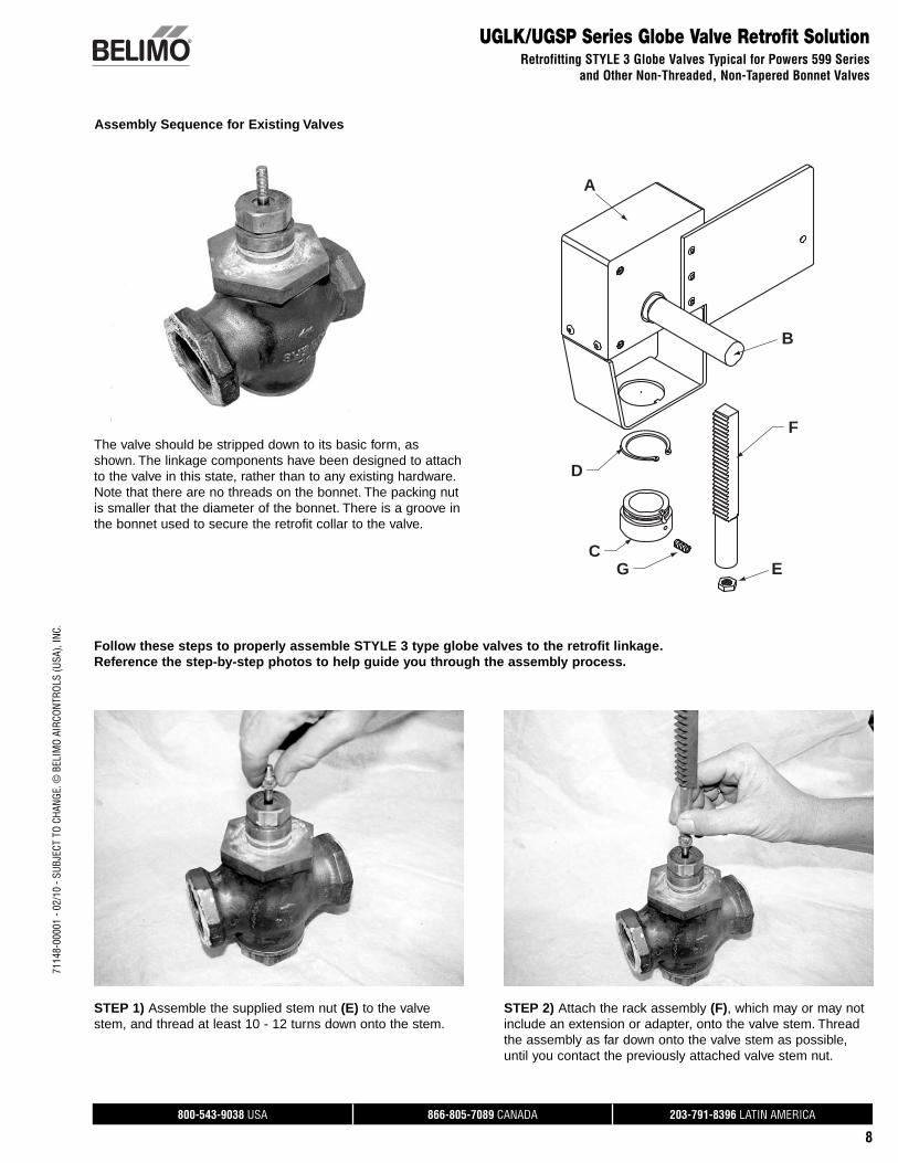
UGLK/UGSP Series Globe Valve Retrofit SolutionRetrofitting STYLE 3 Globe Valves Typical for Powers 599 Series
and Other Non-Threaded, Non-Tapered Bonnet Valves
Assembly Sequence for Existing Valves
The valve should be stripped down to its basic form, as shown. The linkage components have been designed to attach to the valve in this state, rather than to any existing hardware. Note that there are no threads on the bonnet. The packing nut is smaller that the diameter of the bonnet. There is a groove in the bonnet used to secure the retrofit collar to the valve.
Follow these steps to properly assemble STYLE 3 type globe valves to the retrofit linkage. Reference the step-by-step photos to help guide you through the assembly process.
A
C
D
F
B
EG
STEP 1) Assemble the supplied stem nut (E) to the valve stem, and thread at least 10 - 12 turns down onto the stem.
STEP 2) Attach the rack assembly (F), which may or may not include an extension or adapter, onto the valve stem. Thread the assembly as far down onto the valve stem as possible, until you contact the previously attached valve stem nut.
800-543-9038 USA 866-805-7089 CANADA 203-791-8396 LATIN AMERICA
9
7114
8-00
001
- 02/
10 -
SUBJ
ECT
TO C
HANG
E. ©
BEL
IMO
AIRC
ONTR
OLS
(USA
), IN
C.
UGLK/UGSP Series Globe Valve Retrofit SolutionRetrofitting STYLE 3 Globe Valves Typical for Powers 599 Series and Other Non-Threaded, Non-Tapered Bonnet Valves
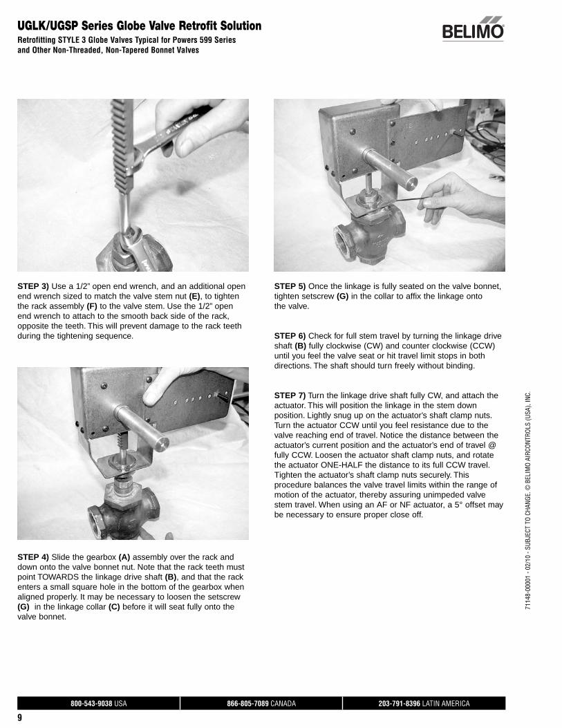
STEP 3) Use a 1/2” open end wrench, and an additional open end wrench sized to match the valve stem nut (E), to tighten the rack assembly (F) to the valve stem. Use the 1/2” open end wrench to attach to the smooth back side of the rack, opposite the teeth. This will prevent damage to the rack teeth during the tightening sequence.
STEP 4) Slide the gearbox (A) assembly over the rack and down onto the valve bonnet nut. Note that the rack teeth must point TOWARDS the linkage drive shaft (B), and that the rack enters a small square hole in the bottom of the gearbox when aligned properly. It may be necessary to loosen the setscrew (G) in the linkage collar (C) before it will seat fully onto the valve bonnet.
STEP 5) Once the linkage is fully seated on the valve bonnet, tighten setscrew (G) in the collar to affix the linkage onto the valve.
STEP 6) Check for full stem travel by turning the linkage drive shaft (B) fully clockwise (CW) and counter clockwise (CCW) until you feel the valve seat or hit travel limit stops in both directions. The shaft should turn freely without binding.
STEP 7) Turn the linkage drive shaft fully CW, and attach the actuator. This will position the linkage in the stem down position. Lightly snug up on the actuator’s shaft clamp nuts. Turn the actuator CCW until you feel resistance due to the valve reaching end of travel. Notice the distance between the actuator’s current position and the actuator’s end of travel @ fully CCW. Loosen the actuator shaft clamp nuts, and rotate the actuator ONE-HALF the distance to its full CCW travel. Tighten the actuator’s shaft clamp nuts securely. This procedure balances the valve travel limits within the range of motion of the actuator, thereby assuring unimpeded valve stem travel. When using an AF or NF actuator, a 5° offset may be necessary to ensure proper close off.
800-543-9038 USA 866-805-7089 CANADA 203-791-8396 LATIN AMERICA
10
7114
8-00
001
- 02/
10 -
SUBJ
ECT
TO C
HANG
E. ©
BEL
IMO
AIRC
ONTR
OLS
(USA
), IN
C.
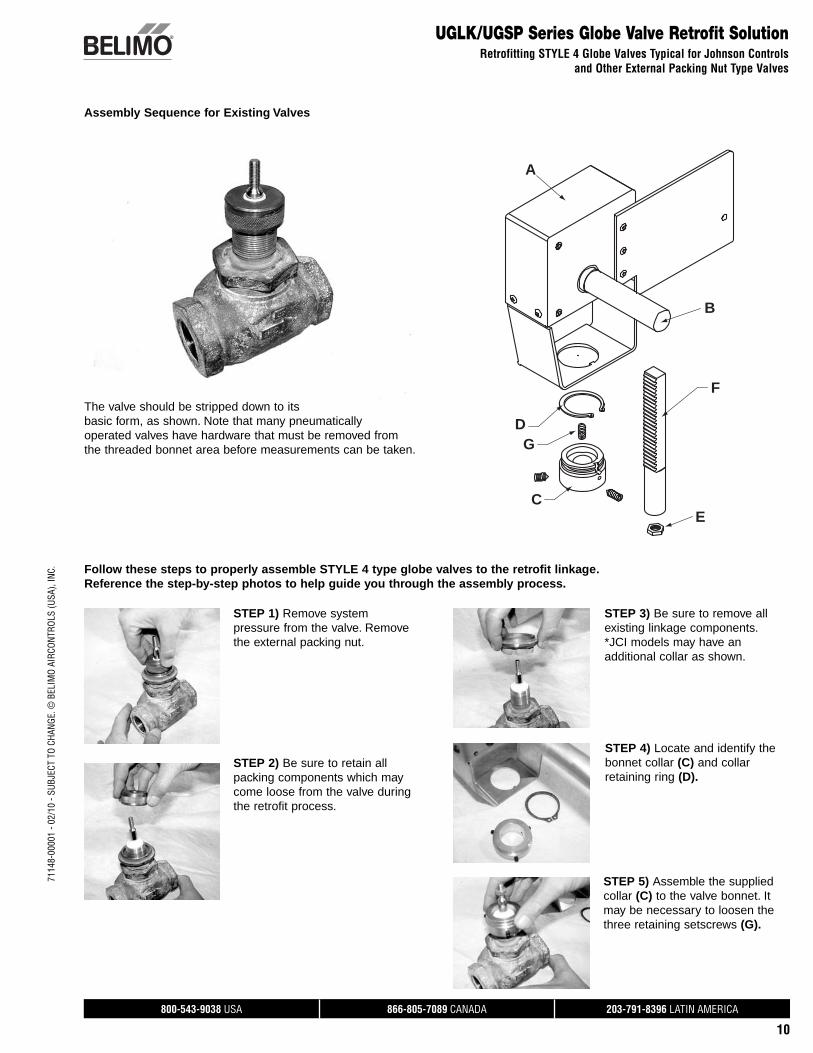
UGLK/UGSP Series Globe Valve Retrofit SolutionRetrofitting STYLE 4 Globe Valves Typical for Johnson Controls
and Other External Packing Nut Type Valves
Assembly Sequence for Existing Valves
A
C
D
F
B
E
G
Follow these steps to properly assemble STYLE 4 type globe valves to the retrofit linkage. Reference the step-by-step photos to help guide you through the assembly process.
The valve should be stripped down to its basic form, as shown. Note that many pneumatically operated valves have hardware that must be removed from the threaded bonnet area before measurements can be taken.
STEP 1) Remove system pressure from the valve. Remove the external packing nut.
STEP 2) Be sure to retain all packing components which may come loose from the valve during the retrofit process.
STEP 3) Be sure to remove all existing linkage components. *JCI models may have an additional collar as shown.
STEP 4) Locate and identify the bonnet collar (C) and collar retaining ring (D).
STEP 5) Assemble the supplied collar (C) to the valve bonnet. It may be necessary to loosen the three retaining setscrews (G).
800-543-9038 USA 866-805-7089 CANADA 203-791-8396 LATIN AMERICA
11
7114
8-00
001
- 02/
10 -
SUBJ
ECT
TO C
HANG
E. ©
BEL
IMO
AIRC
ONTR
OLS
(USA
), IN
C.
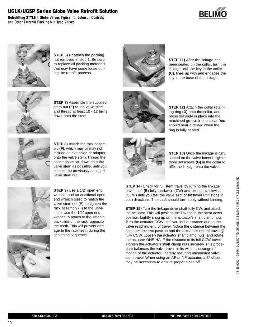
STEP 11) After the linkage has been seated on the collar, turn the linkage until the key in the collar (C), lines up with and engages the key in the base of the linkage.
STEP 12) Attach the collar retain-ing ring (D) onto the collar, and press securely in place into the machined groove in the collar. You should hear a “snap” when the ring is fully seated.
STEP 13) Once the linkage is fully seated on the valve bonnet, tighten three setscrews (G) in the collar to affix the linkage onto the valve.
STEP 14) Check for full stem travel by turning the linkage drive shaft (B) fully clockwise (CW) and counter clockwise (CCW) until you feel the valve seat or hit travel limit stops in both directions. The shaft should turn freely without binding.
STEP 15) Turn the linkage drive shaft fully CW, and attach the actuator. This will position the linkage in the stem down position. Lightly snug up on the actuator’s shaft clamp nuts. Turn the actuator CCW until you feel resistance due to the valve reaching end of travel. Notice the distance between the actuator’s current position and the actuator’s end of travel @ fully CCW. Loosen the actuator shaft clamp nuts, and rotate the actuator ONE-HALF the distance to its full CCW travel. Tighten the actuator’s shaft clamp nuts securely. This proce-dure balances the valve travel limits within the range of motion of the actuator, thereby assuring unimpeded valve stem travel. When using an AF or NF actuator, a 5° offset may be necessary to ensure proper close off.
UGLK/UGSP Series Globe Valve Retrofit SolutionRetrofitting STYLE 4 Globe Valves Typical for Johnson Controls and Other External Packing Nut Type Valves
STEP 6) Reattach the packing nut removed in step 1. Be sure to replace all packing materials that may have come loose dur-ing the retrofit process.
STEP 7) Assemble the supplied stem nut (E) to the valve stem, and thread at least 10 - 12 turns down onto the stem.
STEP 8) Attach the rack assem-bly (F), which may or may not include an extension or adapter, onto the valve stem. Thread the assembly as far down onto the valve stem as possible, until you contact the previously attached valve stem nut.
STEP 9) Use a 1/2” open end wrench, and an additional open end wrench sized to match the valve stem nut (E), to tighten the rack assembly (F) to the valve stem. Use the 1/2” open end wrench to attach to the smooth back side of the rack, opposite the teeth. This will prevent dam-age to the rack teeth during the tightening sequence.
800-543-9038 USA 866-805-7089 CANADA 203-791-8396 LATIN AMERICA
12
7114
8-00
001
- 02/
10 -
SUBJ
ECT
TO C
HANG
E. ©
BEL
IMO
AIRC
ONTR
OLS
(USA
), IN
C.
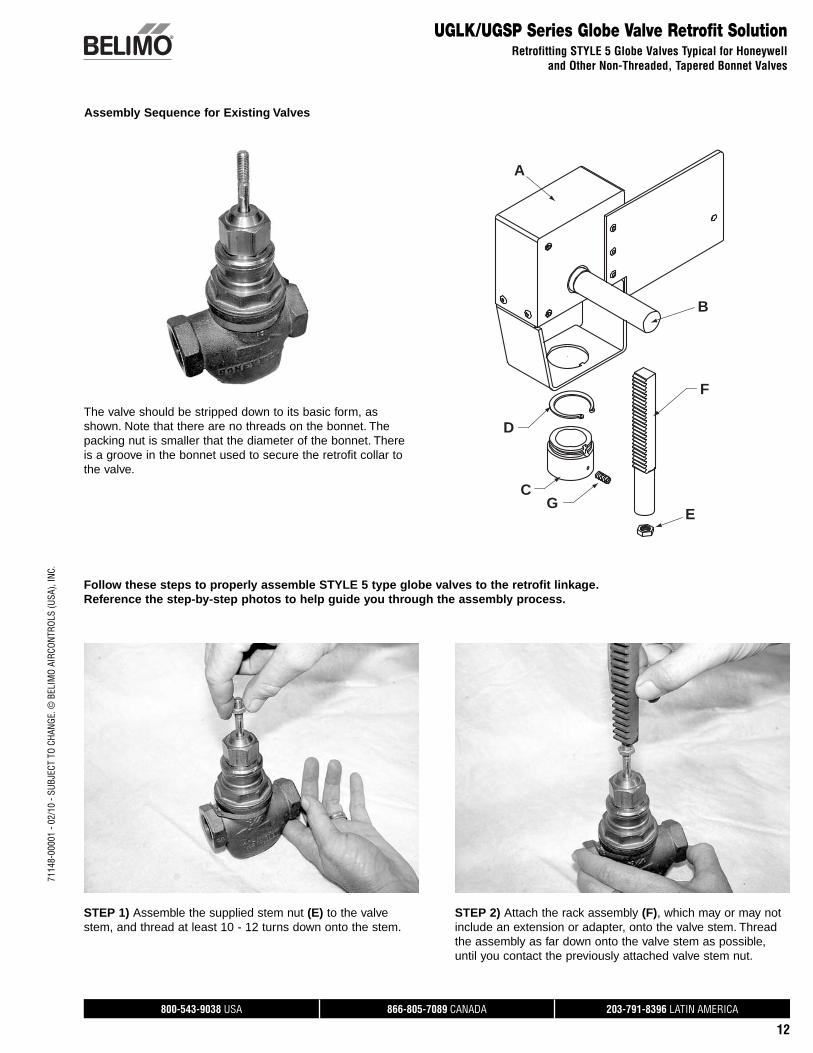
UGLK/UGSP Series Globe Valve Retrofit SolutionRetrofitting STYLE 5 Globe Valves Typical for Honeywell
and Other Non-Threaded, Tapered Bonnet Valves
Assembly Sequence for Existing Valves
The valve should be stripped down to its basic form, as shown. Note that there are no threads on the bonnet. The packing nut is smaller that the diameter of the bonnet. There is a groove in the bonnet used to secure the retrofit collar to the valve.
Follow these steps to properly assemble STYLE 5 type globe valves to the retrofit linkage. Reference the step-by-step photos to help guide you through the assembly process.
A
C
D
F
B
EG
STEP 1) Assemble the supplied stem nut (E) to the valve stem, and thread at least 10 - 12 turns down onto the stem.
STEP 2) Attach the rack assembly (F), which may or may not include an extension or adapter, onto the valve stem. Thread the assembly as far down onto the valve stem as possible, until you contact the previously attached valve stem nut.
800-543-9038 USA 866-805-7089 CANADA 203-791-8396 LATIN AMERICA
13
7114
8-00
001
- 02/
10 -
SUBJ
ECT
TO C
HANG
E. ©
BEL
IMO
AIRC
ONTR
OLS
(USA
), IN
C.
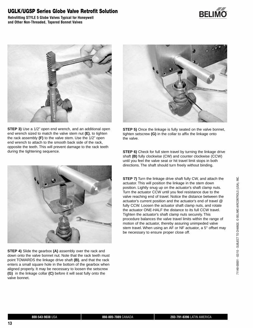
UGLK/UGSP Series Globe Valve Retrofit SolutionRetrofitting STYLE 5 Globe Valves Typical for Honeywell and Other Non-Threaded, Tapered Bonnet Valves
STEP 3) Use a 1/2” open end wrench, and an additional open end wrench sized to match the valve stem nut (E), to tighten the rack assembly (F) to the valve stem. Use the 1/2” open end wrench to attach to the smooth back side of the rack, opposite the teeth. This will prevent damage to the rack teeth during the tightening sequence.
STEP 4) Slide the gearbox (A) assembly over the rack and down onto the valve bonnet nut. Note that the rack teeth must point TOWARDS the linkage drive shaft (B), and that the rack enters a small square hole in the bottom of the gearbox when aligned properly. It may be necessary to loosen the setscrew (G) in the linkage collar (C) before it will seat fully onto the valve bonnet.
STEP 5) Once the linkage is fully seated on the valve bonnet, tighten setscrew (G) in the collar to affix the linkage onto the valve.
STEP 6) Check for full stem travel by turning the linkage drive shaft (B) fully clockwise (CW) and counter clockwise (CCW) until you feel the valve seat or hit travel limit stops in both directions. The shaft should turn freely without binding.
STEP 7) Turn the linkage drive shaft fully CW, and attach the actuator. This will position the linkage in the stem down position. Lightly snug up on the actuator’s shaft clamp nuts. Turn the actuator CCW until you feel resistance due to the valve reaching end of travel. Notice the distance between the actuator’s current position and the actuator’s end of travel @ fully CCW. Loosen the actuator shaft clamp nuts, and rotate the actuator ONE-HALF the distance to its full CCW travel. Tighten the actuator’s shaft clamp nuts securely. This procedure balances the valve travel limits within the range of motion of the actuator, thereby assuring unimpeded valve stem travel. When using an AF or NF actuator, a 5° offset may be necessary to ensure proper close off.
800-543-9038 USA 866-805-7089 CANADA 203-791-8396 LATIN AMERICA
14
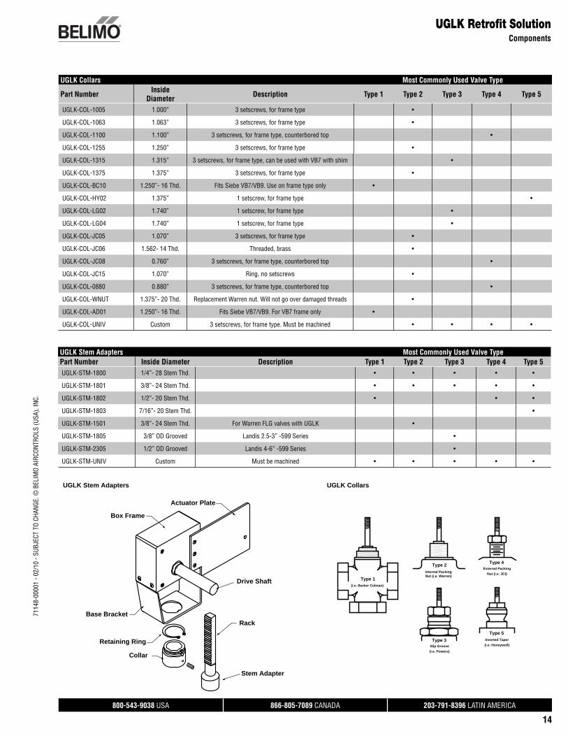
UGLK Collars Most Commonly Used Valve Type
Part Number Inside Diameter Description Type 1 Type 2 Type 3 Type 4 Type 5
UGLK-COL-1005 1.000” 3 setscrews, for frame type •
UGLK-COL-1063 1.063” 3 setscrews, for frame type •
UGLK-COL-1100 1.100” 3 setscrews, for frame type, counterbored top •
UGLK-COL-1255 1.250” 3 setscrews, for frame type •
UGLK-COL-1315 1.315” 3 setscrews, for frame type, can be used with VB7 with shim •
UGLK-COL-1375 1.375” 3 setscrews, for frame type •
UGLK-COL-BC10 1.250”- 16 Thd. Fits Siebe VB7/VB9. Use on frame type only •
UGLK-COL-HY02 1.375” 1 setscrew, for frame type •
UGLK-COL-LG02 1.740” 1 setscrew, for frame type •
UGLK-COL-LG04 1.740” 1 setscrew, for frame type •
UGLK-COL-JC05 1.070” 3 setscrews, for frame type •
UGLK-COL-JC06 1.562- 14 Thd. Threaded, brass •
UGLK-COL-JC08 0.760” 3 setscrews, for frame type, counterbored top •
UGLK-COL-JC15 1.070” Ring, no setscrews •
UGLK-COL-0880 0.880” 3 setscrews, for frame type, counterbored top •
UGLK-COL-WNUT 1.375”- 20 Thd. Replacement Warren nut. Will not go over damaged threads •
UGLK-COL-AD01 1.250”- 16 Thd. Fits Siebe VB7/VB9. For VB7 frame only •
UGLK-COL-UNIV Custom 3 setscrews, for frame type. Must be machined • • • •
UGLK Retrofi t SolutionComponents
UGLK Stem Adapters Most Commonly Used Valve TypePart Number Inside Diameter Description Type 1 Type 2 Type 3 Type 4 Type 5UGLK-STM-1800 1/4”- 28 Stem Thd. • • • • •
UGLK-STM-1801 3/8”- 24 Stem Thd. • • • • •
UGLK-STM-1802 1/2”- 20 Stem Thd. • • •
UGLK-STM-1803 7/16”- 20 Stem Thd. •
UGLK-STM-1501 3/8”- 24 Stem Thd. For Warren FLG valves with UGLK •
UGLK-STM-1805 3/8” OD Grooved Landis 2.5-3” -599 Series •
UGLK-STM-2305 1/2” OD Grooved Landis 4-6” -599 Series •
UGLK-STM-UNIV Custom Must be machined • • • • •
Drive Shaft
Box Frame
Retaining Ring
Collar
Stem Adapter
RackBase Bracket
Actuator Plate
(i.e. Barber Colman)
Type 1
Type 3
Type 2 Type 4
Type 5
Nut (i.e. Warren)Internal Packing
Slip Groove
External Packing
Inverted Taper
(i.e. Powers)
Nut (i.e. JCI)
(i.e. Honeywell)
UGLK Part Overview UGLK Collar InterfacesUGLK Stem Adapters UGLK Collars
7114
8-00
001
- 02/
10 -
SUBJ
ECT
TO C
HANG
E. ©
BEL
IMO
AIRC
ONTR
OLS
(USA
), IN
C.
800-543-9038 USA 866-805-7089 CANADA 203-791-8396 LATIN AMERICA
15
7114
8-00
001
- 02/
10 -
SUBJ
ECT
TO C
HANG
E. ©
BEL
IMO
AIRC
ONTR
OLS
(USA
), IN
C.
Assembly Sequence for Existing Valves
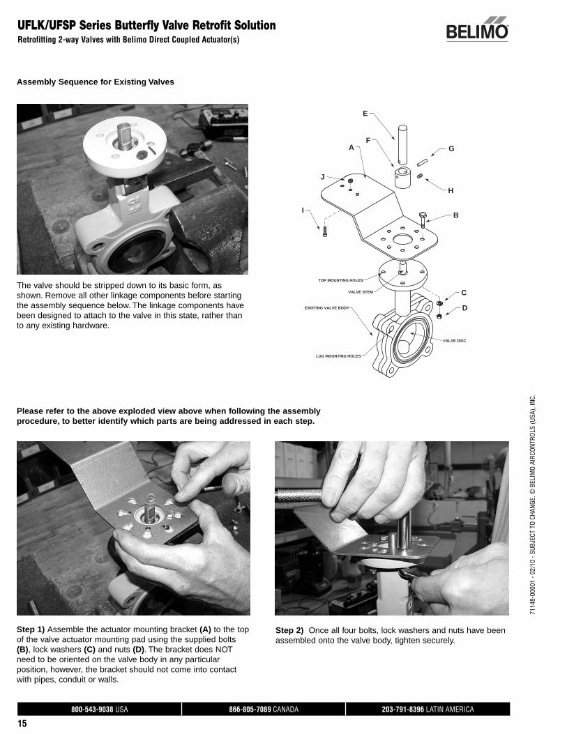
UFLK/UFSP Series Butterfly Valve Retrofit SolutionRetrofitting 2-way Valves with Belimo Direct Coupled Actuator(s)
EXISTING VALVE BODY
VALVE STEM
TOP MOUNTING HOLES
VALVE DISC
LUG MOUNTING HOLES
A
B
C
D
E
FG
H
I
J
Please refer to the above exploded view above when following the assembly procedure, to better identify which parts are being addressed in each step.
The valve should be stripped down to its basic form, as shown. Remove all other linkage components before starting the assembly sequence below. The linkage components have been designed to attach to the valve in this state, rather than to any existing hardware.
Step 1) Assemble the actuator mounting bracket (A) to the top of the valve actuator mounting pad using the supplied bolts (B), lock washers (C) and nuts (D). The bracket does NOT need to be oriented on the valve body in any particular position, however, the bracket should not come into contact with pipes, conduit or walls.
Step 2) Once all four bolts, lock washers and nuts have been assembled onto the valve body, tighten securely.
800-543-9038 USA 866-805-7089 CANADA 203-791-8396 LATIN AMERICA
16
7114
8-00
001
- 02/
10 -
SUBJ
ECT
TO C
HANG
E. ©
BEL
IMO
AIRC
ONTR
OLS
(USA
), IN
C.UFLK/UFSP Series Butterfly Valve Retrofit Solution
Retrofitting 2-way Valves with Belimo Direct Coupled Actuator(s)
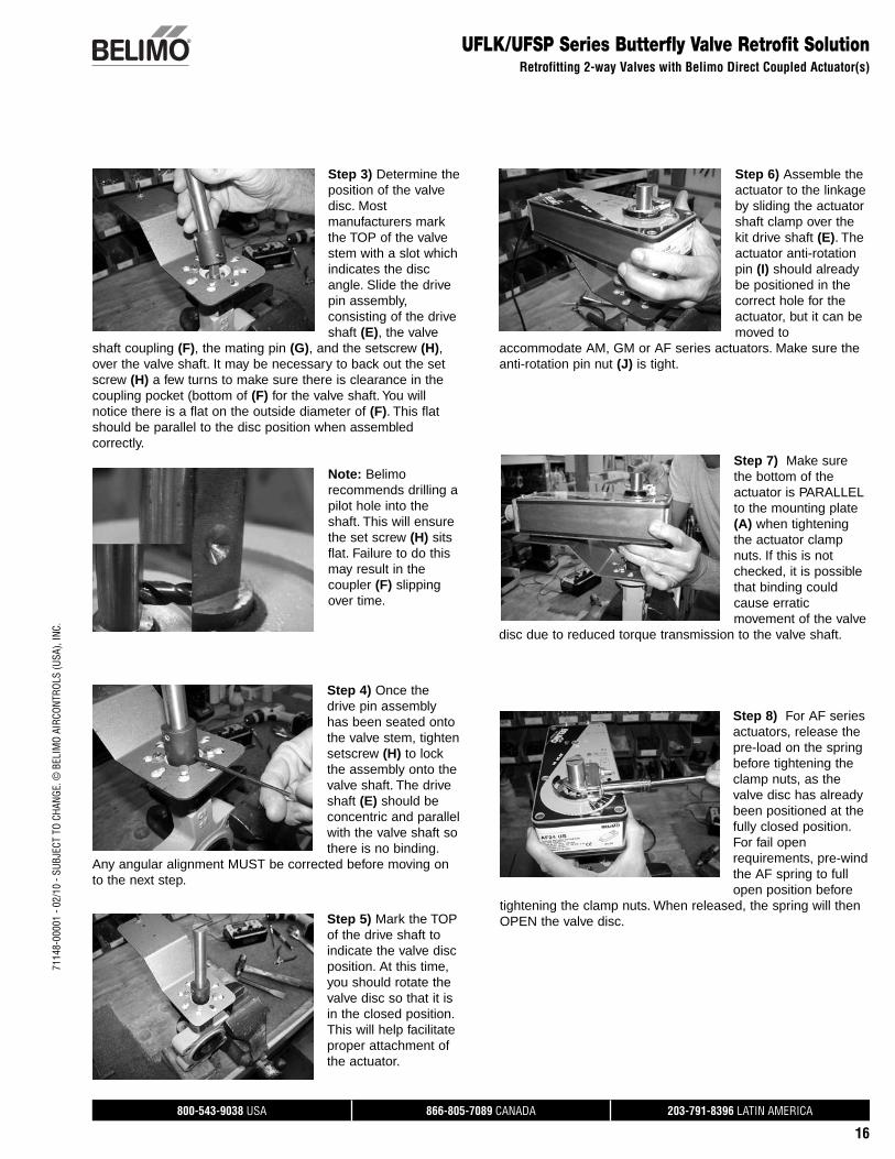
Step 3) Determine the position of the valve disc. Most manufacturers mark the TOP of the valve stem with a slot which indicates the disc angle. Slide the drive pin assembly, consisting of the drive shaft (E), the valve
shaft coupling (F), the mating pin (G), and the setscrew (H), over the valve shaft. It may be necessary to back out the set screw (H) a few turns to make sure there is clearance in the coupling pocket (bottom of (F) for the valve shaft. You will notice there is a flat on the outside diameter of (F). This flat should be parallel to the disc position when assembled correctly.
Step 4) Once the drive pin assembly has been seated onto the valve stem, tighten setscrew (H) to lock the assembly onto the valve shaft. The drive shaft (E) should be concentric and parallel with the valve shaft so there is no binding.
Any angular alignment MUST be corrected before moving on to the next step.
Step 5) Mark the TOP of the drive shaft to indicate the valve disc position. At this time, you should rotate the valve disc so that it is in the closed position. This will help facilitate proper attachment of the actuator.
Step 6) Assemble the actuator to the linkage by sliding the actuator shaft clamp over the kit drive shaft (E). The actuator anti-rotation pin (I) should already be positioned in the correct hole for the actuator, but it can be moved to
accommodate AM, GM or AF series actuators. Make sure the anti-rotation pin nut (J) is tight.
Step 7) Make sure the bottom of the actuator is PARALLEL to the mounting plate (A) when tightening the actuator clamp nuts. If this is not checked, it is possible that binding could cause erratic movement of the valve
disc due to reduced torque transmission to the valve shaft.
Step 8) For AF series actuators, release the pre-load on the spring before tightening the clamp nuts, as the valve disc has already been positioned at the fully closed position. For fail open requirements, pre-wind the AF spring to full open position before
tightening the clamp nuts. When released, the spring will then OPEN the valve disc.
Note: Belimo recommends drilling a pilot hole into the shaft. This will ensure the set screw (H) sits flat. Failure to do this may result in the coupler (F) slipping over time.
800-543-9038 USA 866-805-7089 CANADA 203-791-8396 LATIN AMERICA
17
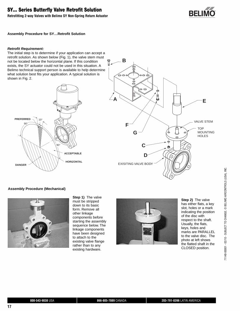
SY… Series Butterfly Valve Retrofit SolutionRetrofitting 2-way Valves with Belimo SY Non-Spring Return Actuator
Assembly Procedure for SY…Retrofit Solution
PREFERRED
DANGER
ACCEPTABLE
HORIZONTAL
90°
90°
10°
Retrofit Requirement: The initial step is to determine if your application can accept a retrofit solution. As shown below (Fig. 1), the valve stem must not be located below the horizontal plane. If this condition exists, the SY actuator could not be used in this situation. A Belimo technical support person is available to help determine what solution best fits your application. A typical solution is shown in Fig. 2.
Step 1) The valve must be stripped down to its basic form. Remove all other linkage components before starting the assembly sequence below. The linkage components have been designed to attach to the existing valve flange rather than to any existing hardware.
Step 2) The valve has either flats, a key slot, holes or a mark indicating the position of the disc with respect to the shaft. Usually, the flats, keys, holes and marks are PARALLEL to the valve disc. The photo at left shows the flatted shaft in the CLOSED position.
Assembly Procedure (Mechanical)
B
A
F
G
C
D
E
VALVE STEM
TOP MOUNTING HOLES
EXISITING VALVE BODY
7114
8-00
001
- 02/
10 -
SUBJ
ECT
TO C
HANG
E. ©
BEL
IMO
AIRC
ONTR
OLS
(USA
), IN
C.
800-543-9038 USA 866-805-7089 CANADA 203-791-8396 LATIN AMERICA
18
7114
8-00
001
- 02/
10 -
SUBJ
ECT
TO C
HANG
E. ©
BEL
IMO
AIRC
ONTR
OLS
(USA
), IN
C.SY… Series Butterfly Valve Retrofit Solution
Retrofitting 2-way Valves with Belimo SY Non-Spring Return Actuator
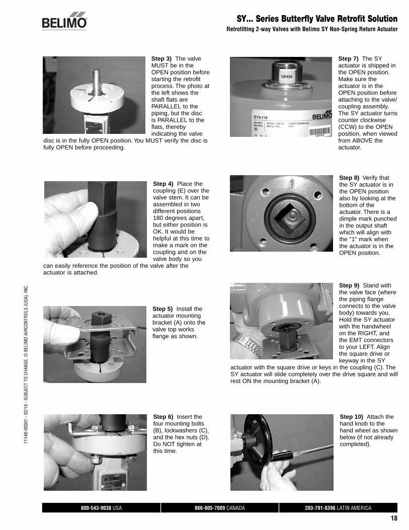
Step 3) The valve MUST be in the OPEN position before starting the retrofit process. The photo at the left shows the shaft flats are PARALLEL to the piping, but the disc is PARALLEL to the flats, thereby indicating the valve
disc is in the fully OPEN position. You MUST verify the disc is fully OPEN before proceeding.
Step 4) Place the coupling (E) over the valve stem. It can be assembled in two different positions 180 degrees apart, but either position is OK. It would be helpful at this time to make a mark on the coupling and on the valve body so you
can easily reference the position of the valve after the actuator is attached.
Step 5) Install the actuator mounting bracket (A) onto the valve top works flange as shown.
Step 6) Insert the four mounting bolts (B), lockwashers (C), and the hex nuts (D). Do NOT tighten at this time.
Step 7) The SY actuator is shipped in the OPEN position. Make sure the actuator is in the OPEN position before attaching to the valve/coupling assembly. The SY actuator turns counter clockwise (CCW) to the OPEN position, when viewed from ABOVE the actuator.
Step 8) Verify that the SY actuator is in the OPEN position also by looking at the bottom of the actuator. There is a dimple mark punched in the output shaft which will align with the "1" mark when the actuator is in the OPEN position.
Step 9) Stand with the valve face (where the piping flange connects to the valve body) towards you. Hold the SY actuator with the handwheel on the RIGHT, and the EMT connectors to your LEFT. Align the square drive or keyway in the SY
actuator with the square drive or keys in the coupling (C). The SY actuator will slide completely over the drive square and will rest ON the mounting bracket (A).
Step 10) Attach the hand knob to the hand wheel as shown below (if not already completed).
800-543-9038 USA 866-805-7089 CANADA 203-791-8396 LATIN AMERICA
19
7114
8-00
001
- 02/
10 -
SUBJ
ECT
TO C
HANG
E. ©
BEL
IMO
AIRC
ONTR
OLS
(USA
), IN
C.
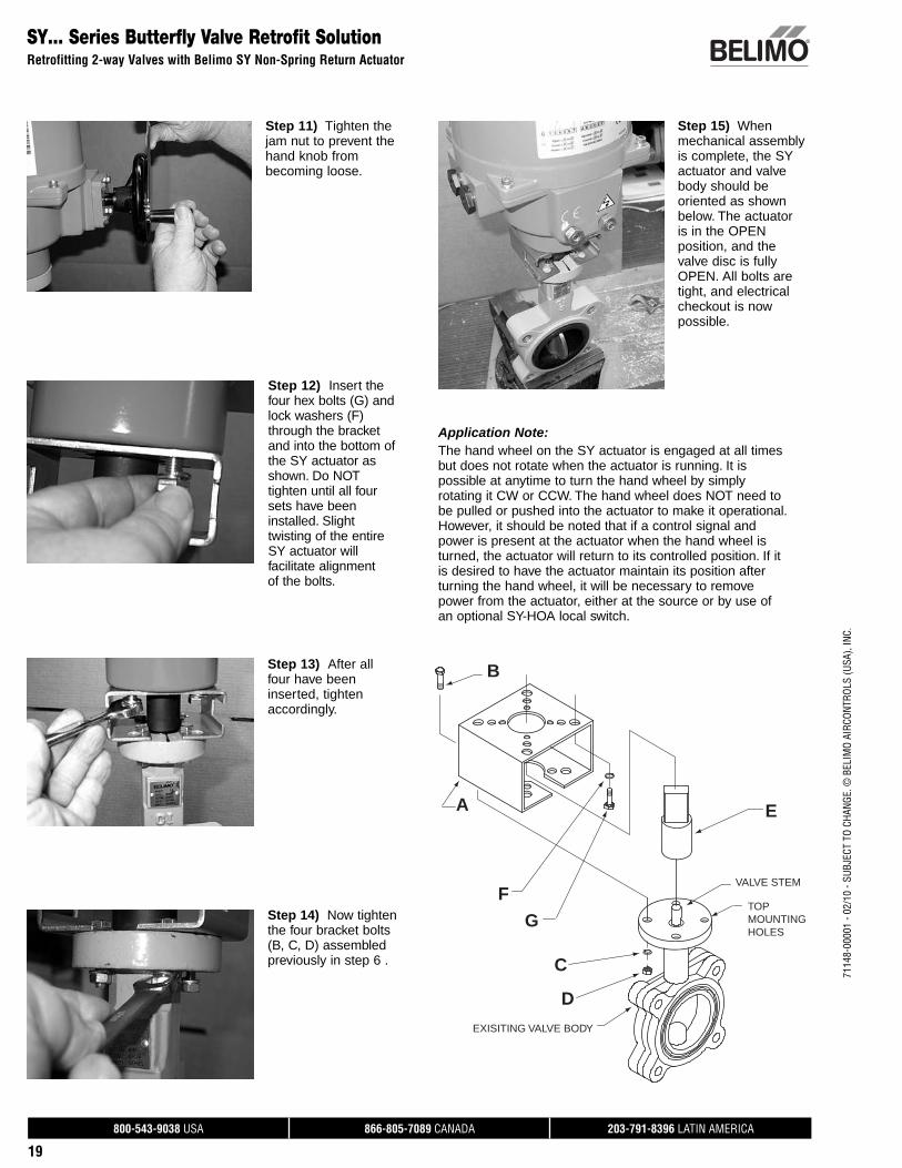
Step 11) Tighten the jam nut to prevent the hand knob from becoming loose.
Step 12) Insert the four hex bolts (G) and lock washers (F) through the bracket and into the bottom of the SY actuator as shown. Do NOT tighten until all four sets have been installed. Slight twisting of the entire SY actuator will facilitate alignment
of the bolts.
Step 13) After all four have been inserted, tighten accordingly.
Step 14) Now tighten the four bracket bolts (B, C, D) assembled previously in step 6 .
Step 15) When mechanical assembly is complete, the SY actuator and valve body should be oriented as shown below. The actuator is in the OPEN position, and the valve disc is fully OPEN. All bolts are tight, and electrical checkout is now possible.
SY… Series Butterfly Valve Retrofit SolutionRetrofitting 2-way Valves with Belimo SY Non-Spring Return Actuator
Application Note: The hand wheel on the SY actuator is engaged at all times but does not rotate when the actuator is running. It is possible at anytime to turn the hand wheel by simply rotating it CW or CCW. The hand wheel does NOT need to be pulled or pushed into the actuator to make it operational. However, it should be noted that if a control signal and power is present at the actuator when the hand wheel is turned, the actuator will return to its controlled position. If it is desired to have the actuator maintain its position after turning the hand wheel, it will be necessary to remove power from the actuator, either at the source or by use of an optional SY-HOA local switch.
B
A
F
G
C
D
E
VALVE STEM
TOP MOUNTING HOLES
EXISITING VALVE BODY
800-543-9038 USA 866-805-7089 CANADA 203-791-8396 LATIN AMERICA
20
7114
8-00
001
- 02/
10 -
SUBJ
ECT
TO C
HANG
E. ©
BEL
IMO
AIRC
ONTR
OLS
(USA
), IN
C.SY… Series Butterfly Valve Retrofit Solution
Retrofitting 2-way Valves with Belimo SY On/Off Non-Spring Return Actuator
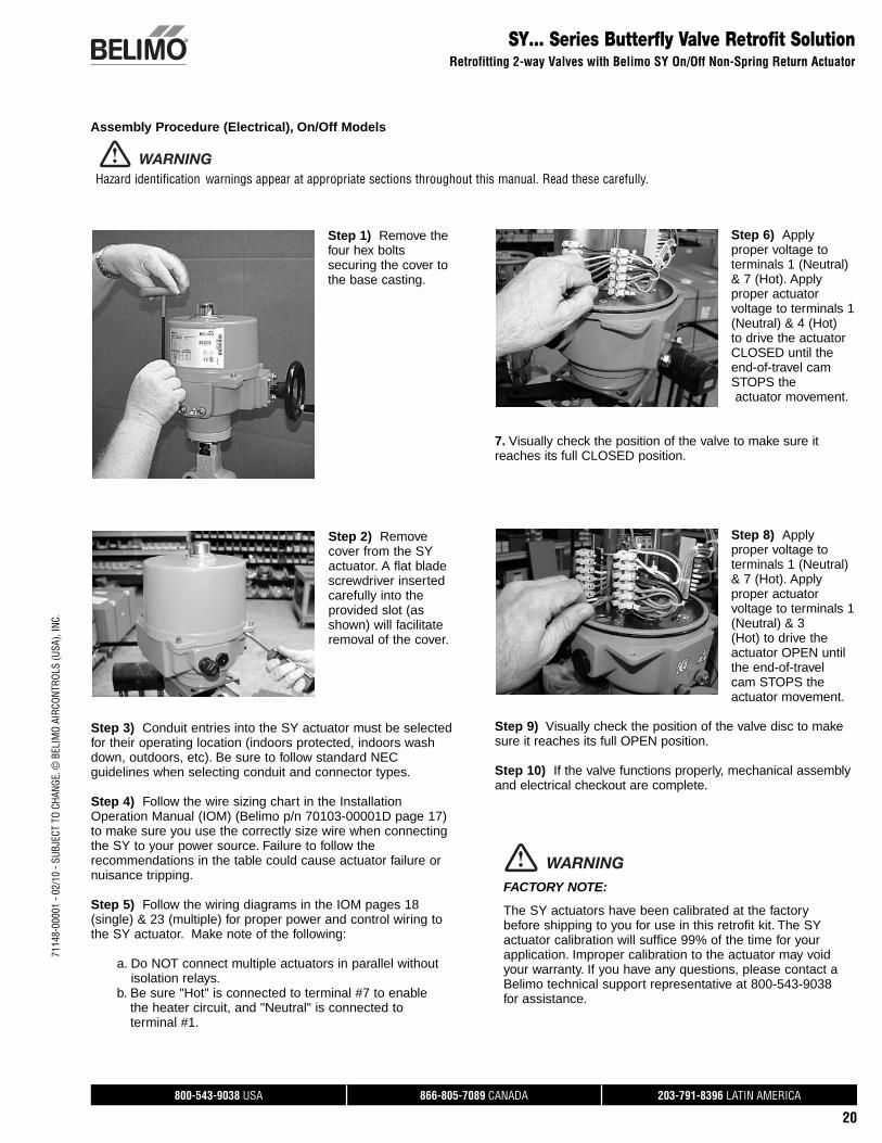
Step 1) Remove the four hex bolts securing the cover to the base casting.
Step 2) Remove cover from the SY actuator. A flat blade screwdriver inserted carefully into the provided slot (as shown) will facilitate removal of the cover.
Step 3) Conduit entries into the SY actuator must be selected for their operating location (indoors protected, indoors wash down, outdoors, etc). Be sure to follow standard NEC guidelines when selecting conduit and connector types.
Step 4) Follow the wire sizing chart in the Installation Operation Manual (IOM) (Belimo p/n 70103-00001D page 17) to make sure you use the correctly size wire when connecting the SY to your power source. Failure to follow the recommendations in the table could cause actuator failure or nuisance tripping.
Step 5) Follow the wiring diagrams in the IOM pages 18 (single) & 23 (multiple) for proper power and control wiring to the SY actuator. Make note of the following:
a. Do NOT connect multiple actuators in parallel without isolation relays.
b. Be sure "Hot" is connected to terminal #7 to enable the heater circuit, and "Neutral" is connected to terminal #1.
Step 6) Apply proper voltage to terminals 1 (Neutral) & 7 (Hot). Apply proper actuator voltage to terminals 1 (Neutral) & 4 (Hot) to drive the actuator CLOSED until the end-of-travel cam STOPS the actuator movement.
7. Visually check the position of the valve to make sure it reaches its full CLOSED position.
Step 8) Apply proper voltage to terminals 1 (Neutral) & 7 (Hot). Apply proper actuator voltage to terminals 1 (Neutral) & 3(Hot) to drive the actuator OPEN until the end-of-travel cam STOPS the actuator movement.
Step 9) Visually check the position of the valve disc to make sure it reaches its full OPEN position.
Step 10) If the valve functions properly, mechanical assembly and electrical checkout are complete.
Assembly Procedure (Electrical), On/Off Models
FACTORY NOTE:
The SY actuators have been calibrated at the factory before shipping to you for use in this retrofit kit. The SY actuator calibration will suffice 99% of the time for your application. Improper calibration to the actuator may void your warranty. If you have any questions, please contact a Belimo technical support representative at 800-543-9038 for assistance.
WARNING
Hazard identification warnings appear at appropriate sections throughout this manual. Read these carefully.
WARNING
800-543-9038 USA 866-805-7089 CANADA 203-791-8396 LATIN AMERICA
21
7114
8-00
001
- 02/
10 -
SUBJ
ECT
TO C
HANG
E. ©
BEL
IMO
AIRC
ONTR
OLS
(USA
), IN
C.
SY… Series Butterfly Valve Retrofit SolutionRetrofitting 2-way Valves with Belimo SY Proportional Non-Spring Return Actuator
Assembly Procedure (Electrical), Proportional Models
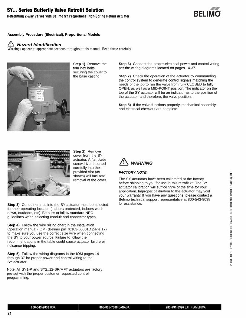
Step 1) Remove the four hex bolts securing the cover to the base casting.
Step 2) Remove cover from the SY actuator. A flat blade screwdriver inserted carefully into the provided slot (as shown) will facilitate removal of the cover.
Step 3) Conduit entries into the SY actuator must be selected for their operating location (indoors protected, indoors wash down, outdoors, etc). Be sure to follow standard NEC guidelines when selecting conduit and connector types.
Step 4) Follow the wire sizing chart in the Installation Operation manual (IOM) (Belimo p/n 70103-00001D page 17) to make sure you use the correct size wire when connecting the SY to your power source. Failure to follow the recommendations in the table could cause actuator failure or nuisance tripping.
Step 5) Follow the wiring diagrams in the IOM pages 14 through 37 for proper power and control wiring to the SY actuator.
Note: All SY1-P and SY2..12-SR/MFT actuators are factory pre-set with the proper customer requested control programming.
Step 6) Connect the proper electrical power and control wiring per the wiring diagrams located on pages 14-37.
Step 7) Check the operation of the actuator by commanding the control system to generate control signals matching the needs of the job to run the valve from fully CLOSED to fully OPEN, as well as a MID-POINT position. The indicator on the top of the SY actuator will be an indicator as to the position of the actuator, and therefore, the valve position.
Step 8) If the valve functions properly, mechanical assembly and electrical checkout are complete.
FACTORY NOTE:
The SY actuators have been calibrated at the factory before shipping to you for use in this retrofit kit. The SY actuator calibration will suffice 99% of the time for your application. Improper calibration to the actuator may void your warranty. If you have any questions, please contact a Belimo technical support representative at 800-543-9038 for assistance.
WARNING
Hazard IdentificationWarnings appear at appropriate sections throughout this manual. Read these carefully.
800-543-9038 USA 866-805-7089 CANADA 203-791-8396 LATIN AMERICA
22
7114
8-00
001
- 02/
10 -
SUBJ
ECT
TO C
HANG
E. ©
BEL
IMO
AIRC
ONTR
OLS
(USA
), IN
C.UFLK/UFSP Series Butterfly Valve Retrofit Solution
Retrofitting 3-way Valves with Belimo Direct Coupled Actuator(s)
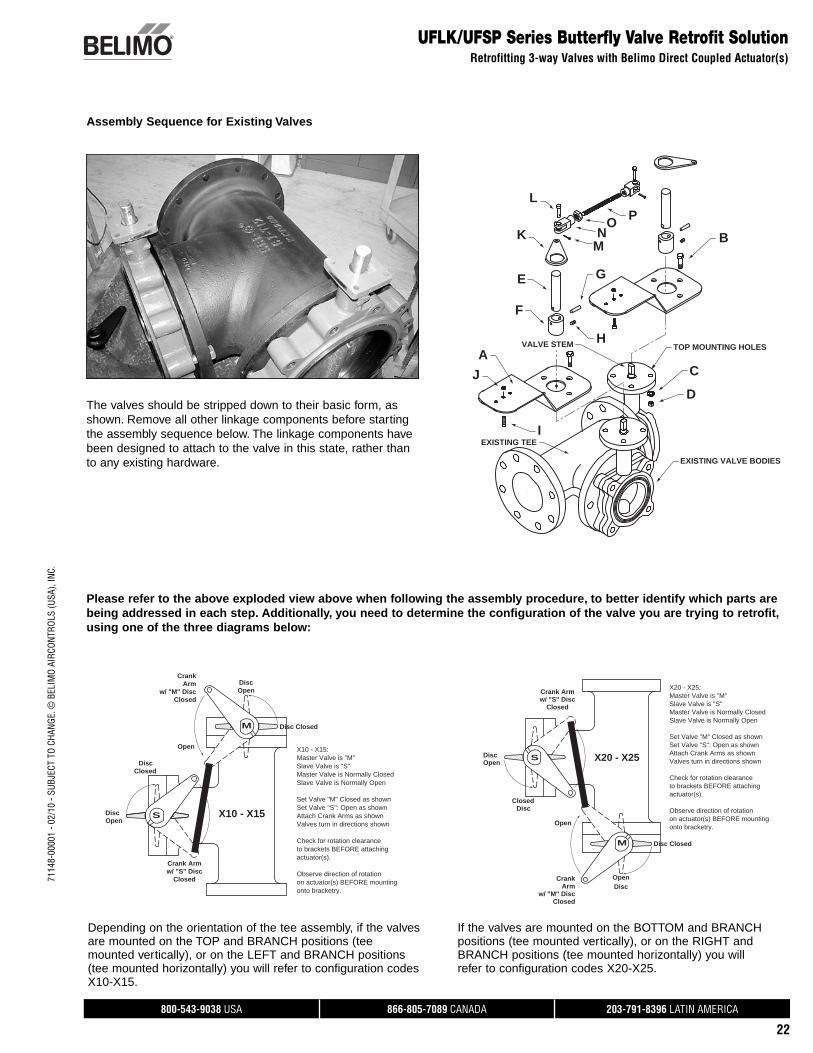
Assembly Sequence for Existing Valves
A
B
C
D
E
F
G
H
I
J
K
L
MN
O P
TOP MOUNTING HOLESVALVE STEM
EXISTING VALVE BODIES
EXISTING TEE
Please refer to the above exploded view above when following the assembly procedure, to better identify which parts are being addressed in each step. Additionally, you need to determine the configuration of the valve you are trying to retrofit, using one of the three diagrams below:
The valves should be stripped down to their basic form, as shown. Remove all other linkage components before starting the assembly sequence below. The linkage components have been designed to attach to the valve in this state, rather than to any existing hardware.
Depending on the orientation of the tee assembly, if the valves are mounted on the TOP and BRANCH positions (tee mounted vertically), or on the LEFT and BRANCH positions (tee mounted horizontally) you will refer to configuration codes X10-X15.
Open
Disc Open
DiscClosed
S
Open
Check for rotation clearanceto brackets BEFORE attaching
Observe direction of rotationon actuator(s) BEFORE mountingonto bracketry.
actuator(s).
Disc Closed
X20 - X25:
Slave Valve is "S"Master Valve is "M"
Slave Valve is Normally Open
Set Valve "M" Closed as shownSet Valve "S": Open as shownAttach Crank Arms as shownValves turn in directions shown
Master Valve is Normally Closed
X20 - X25
M
Disc
Closedw/ "M" Disc
ArmCrank
w/ "S" DiscCrank Arm
Closed
M
X10 - X15:Master Valve is "M"Slave Valve is "S"Master Valve is Normally ClosedSlave Valve is Normally Open
Set Valve "M" Closed as shownSet Valve "S": Open as shownAttach Crank Arms as shownValves turn in directions shown
Check for rotation clearanceto brackets BEFORE attachingactuator(s).
Observe direction of rotationon actuator(s) BEFORE mountingonto bracketry.
Disc Closed
DiscOpen
CrankArm
w/ "M" DiscClosed
Open
S
DiscClosed
Disc Open
Crank Armw/ "S" Disc
Closed
X10 - X15
If the valves are mounted on the BOTTOM and BRANCH positions (tee mounted vertically), or on the RIGHT and BRANCH positions (tee mounted horizontally) you will refer to configuration codes X20-X25.
800-543-9038 USA 866-805-7089 CANADA 203-791-8396 LATIN AMERICA
23
7114
8-00
001
- 02/
10 -
SUBJ
ECT
TO C
HANG
E. ©
BEL
IMO
AIRC
ONTR
OLS
(USA
), IN
C.
UFLK/UFSP Series Butterfly Valve Retrofit SolutionRetrofitting 3-way Valves with Belimo Direct Coupled Actuator(s)
Assembly Sequence for Existing Valves
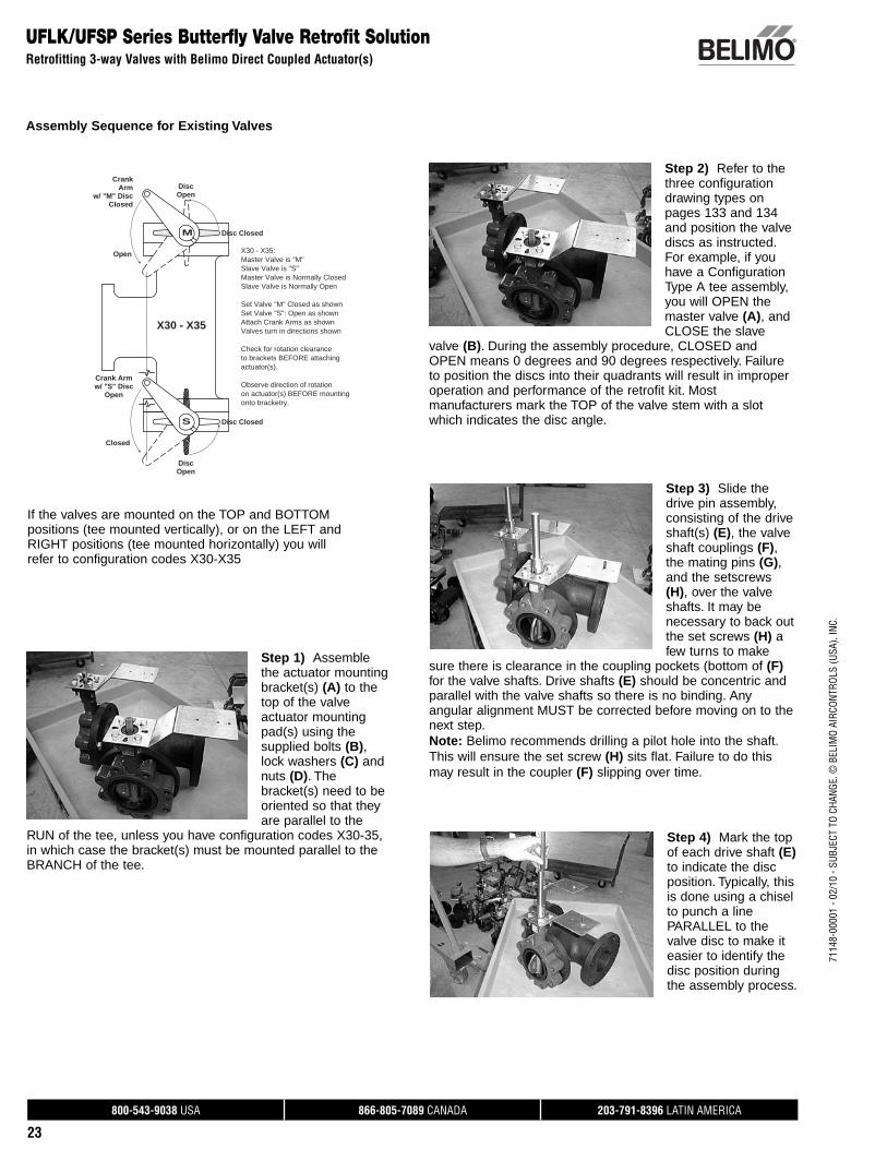
Step 1) Assemble the actuator mounting bracket(s) (A) to the top of the valve actuator mounting pad(s) using the supplied bolts (B), lock washers (C) and nuts (D). The bracket(s) need to be oriented so that they are parallel to the
RUN of the tee, unless you have configuration codes X30-35, in which case the bracket(s) must be mounted parallel to the BRANCH of the tee.
Step 2) Refer to the three configuration drawing types on pages 133 and 134 and position the valve discs as instructed. For example, if you have a Configuration Type A tee assembly, you will OPEN the master valve (A), and CLOSE the slave
valve (B). During the assembly procedure, CLOSED and OPEN means 0 degrees and 90 degrees respectively. Failure to position the discs into their quadrants will result in improper operation and performance of the retrofit kit. Most manufacturers mark the TOP of the valve stem with a slot which indicates the disc angle.
Step 3) Slide the drive pin assembly, consisting of the drive shaft(s) (E), the valve shaft couplings (F), the mating pins (G), and the setscrews (H), over the valve shafts. It may be necessary to back out the set screws (H) a few turns to make
sure there is clearance in the coupling pockets (bottom of (F) for the valve shafts. Drive shafts (E) should be concentric and parallel with the valve shafts so there is no binding. Any angular alignment MUST be corrected before moving on to the next step.Note: Belimo recommends drilling a pilot hole into the shaft. This will ensure the set screw (H) sits flat. Failure to do this may result in the coupler (F) slipping over time.
Step 4) Mark the top of each drive shaft (E) to indicate the disc position. Typically, this is done using a chisel to punch a line PARALLEL to the valve disc to make it easier to identify the disc position during the assembly process.
Open
Master Valve is Normally Closed
Valves turn in directions shownAttach Crank Arms as shownSet Valve "S": Open as shownSet Valve "M" Closed as shown
Slave Valve is Normally Open
Master Valve is "M"Slave Valve is "S"
X30 - X35:
Disc Closed
actuator(s).
onto bracketry.on actuator(s) BEFORE mountingObserve direction of rotation
to brackets BEFORE attachingCheck for rotation clearance
Open
Crank Armw/ "S" Disc
Closedw/ "M" Disc
Open
X30 - X35
M
ArmCrank
Disc
Open
Disc Closed
Closed
S
Disc
If the valves are mounted on the TOP and BOTTOM positions (tee mounted vertically), or on the LEFT and RIGHT positions (tee mounted horizontally) you will refer to configuration codes X30-X35
800-543-9038 USA 866-805-7089 CANADA 203-791-8396 LATIN AMERICA
24
7114
8-00
001
- 02/
10 -
SUBJ
ECT
TO C
HANG
E. ©
BEL
IMO
AIRC
ONTR
OLS
(USA
), IN
C.UFLK/UFSP Series Butterfly Valve Retrofit Solution
Retrofitting 3-way Valves with Belimo Direct Coupled Actuator(s)
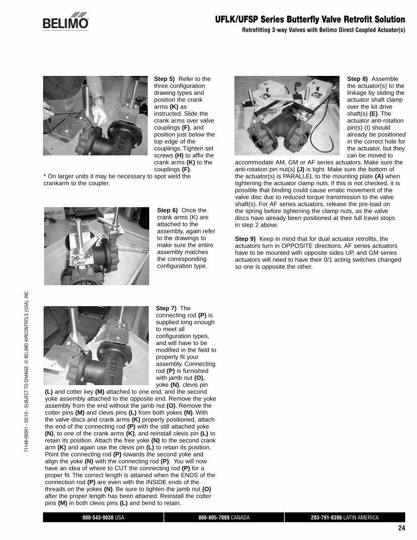
Step 6) Once the crank arms (K) are attached to the assembly, again refer to the drawings to make sure the entire assembly matches the corresponding configuration type.
Step 7) The connecting rod (P) is supplied long enough to meet all configuration types, and will have to be modified in the field to properly fit your assembly. Connecting rod (P) is furnished with jamb nut (O), yoke (N), clevis pin
(L) and cotter key (M) attached to one end, and the second yoke assembly attached to the opposite end. Remove the yoke assembly from the end without the jamb nut (O). Remove the cotter pins (M) and clevis pins (L) from both yokes (N). With the valve discs and crank arms (K) properly positioned, attach the end of the connecting rod (P) with the still attached yoke (N), to one of the crank arms (K), and reinstall clevis pin (L) to retain its position. Attach the free yoke (N) to the second crank arm (K) and again use the clevis pin (L) to retain its position. Point the connecting rod (P) towards the second yoke and align the yoke (N) with the connecting rod (P). You will now have an idea of where to CUT the connecting rod (P) for a proper fit. The correct length is attained when the ENDS of the connection rod (P) are even with the INSIDE ends of the threads on the yokes (N). Be sure to tighten the jamb nut (O) after the proper length has been attained. Reinstall the cotter pins (M) in both clevis pins (L) and bend to retain.
Step 8) Assemble the actuator(s) to the linkage by sliding the actuator shaft clamp over the kit drive shaft(s) (E). The actuator anti-rotation pin(s) (I) should already be positioned in the correct hole for the actuator, but they can be moved to
accommodate AM, GM or AF series actuators. Make sure the anti-rotation pin nut(s) (J) is tight. Make sure the bottom of the actuator(s) is PARALLEL to the mounting plate (A) when tightening the actuator clamp nuts. If this is not checked, it is possible that binding could cause erratic movement of the valve disc due to reduced torque transmission to the valve shaft(s). For AF series actuators, release the pre-load on the spring before tightening the clamp nuts, as the valve discs have already been positioned at their full travel stops in step 2 above.
Step 9) Keep in mind that for dual actuator retrofits, the actuators turn in OPPOSITE directions. AF series actuators have to be mounted with opposite sides UP, and GM series actuators will need to have their 0/1 acting switches changed so one is opposite the other.
Step 5) Refer to the three configuration drawing types and position the crank arms (K) as instructed. Slide the crank arms over valve couplings (F), and position just below the top edge of the couplings. Tighten set screws (H) to affix the crank arms (K) to the couplings (F).
* On larger units it may be necessary to spot weld the crankarm to the coupler.
800-543-9038 USA 866-805-7089 CANADA 203-791-8396 LATIN AMERICA
25
7114
8-00
001
- 02/
10 -
SUBJ
ECT
TO C
HANG
E. ©
BEL
IMO
AIRC
ONTR
OLS
(USA
), IN
C.
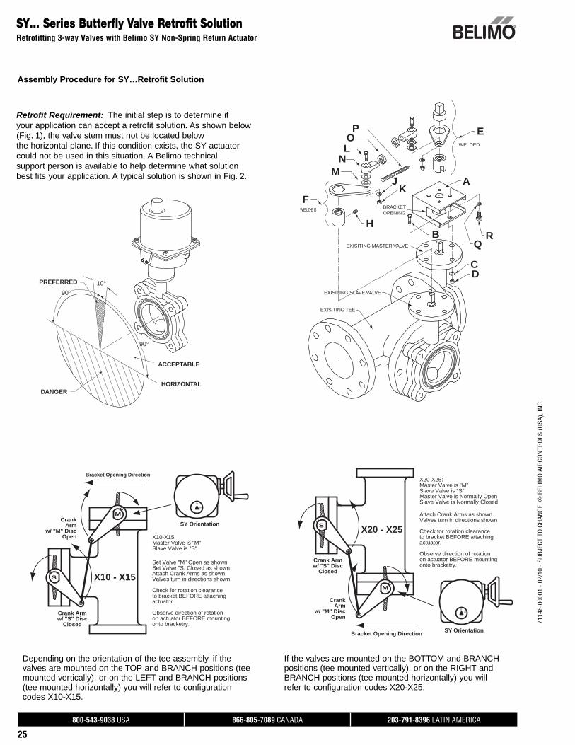
SY… Series Butterfly Valve Retrofit SolutionRetrofitting 3-way Valves with Belimo SY Non-Spring Return Actuator
Assembly Procedure for SY…Retrofit Solution
PREFERRED
DANGER
ACCEPTABLE
HORIZONTAL
90°
90°
10°
O
M
F
LN
A
H
JK
B
CD
QR
P E
EXISITING TEE
EXISITING SLAVE VALVE
EXISITING MASTER VALVE
BRACKET OPENING
WELDED
Retrofit Requirement: The initial step is to determine if your application can accept a retrofit solution. As shown below (Fig. 1), the valve stem must not be located below the horizontal plane. If this condition exists, the SY actuator could not be used in this situation. A Belimo technical support person is available to help determine what solution best fits your application. A typical solution is shown in Fig. 2.
Depending on the orientation of the tee assembly, if the valves are mounted on the TOP and BRANCH positions (tee mounted vertically), or on the LEFT and BRANCH positions (tee mounted horizontally) you will refer to configuration codes X10-X15.
Master Valve is Normally Open
Valves turn in directions shownAttach Crank Arms as shown
Slave Valve is Normally Closed
Check for rotation clearanceto bracket BEFORE attaching
Observe direction of rotationon actuator BEFORE mounting
Bracket Opening Direction
w/ "S" DiscClosed
Crank Arm
w/ "M" Disc
CrankArm
Open
M
onto bracketry.
S
Master Valve is "M"Slave Valve is "S"
actuator.
X20-X25:
SY Orientation
S0
X20 - X25
Bracket Opening Direction
w/ "S" Disc
w/ "M" Disc
S
Closed
Crank Arm
Arm
Open
CrankM
on actuator BEFORE mounting
to bracket BEFORE attaching
Set Valve "M" Open as shown
Observe direction of rotation
Check for rotation clearance
Valves turn in directions shownAttach Crank Arms as shownSet Valve "S: Closed as shown
actuator.
onto bracketry.
X10-X15:
Slave Valve is "S"Master Valve is "M"
SY Orientation
0
S
X10 - X15
If the valves are mounted on the BOTTOM and BRANCH positions (tee mounted vertically), or on the RIGHT and BRANCH positions (tee mounted horizontally) you will refer to configuration codes X20-X25.
800-543-9038 USA 866-805-7089 CANADA 203-791-8396 LATIN AMERICA
26
7114
8-00
001
- 02/
10 -
SUBJ
ECT
TO C
HANG
E. ©
BEL
IMO
AIRC
ONTR
OLS
(USA
), IN
C.SY… Series Butterfly Valve Retrofit Solution
Retrofitting 3-way Valves with Belimo SY Non-Spring Return Actuator
Observe direction of rotation
Check for rotation clearance
Set Valve "S: Closed as shownSet Valve "M" Open as shown
Valves turn in directions shownAttach Crank Arms as shown
to bracket BEFORE attaching
on actuator BEFORE mounting
Bracket Opening Direction
Open
Crank Armw/ "M" Disc
w/ "S" DiscClosed
CrankArm
M
onto bracketry.
actuator.
S
Slave Valve is "S"Master Valve is "M"X30-X35:
X30 - X35
SY Orientation
S0
If the valves are mounted on the TOP and BOTTOM positions (tee mounted vertically), or on the LEFT and RIGHT positions (tee mounted horizontally) you will refer to configuration codes X30-X35.
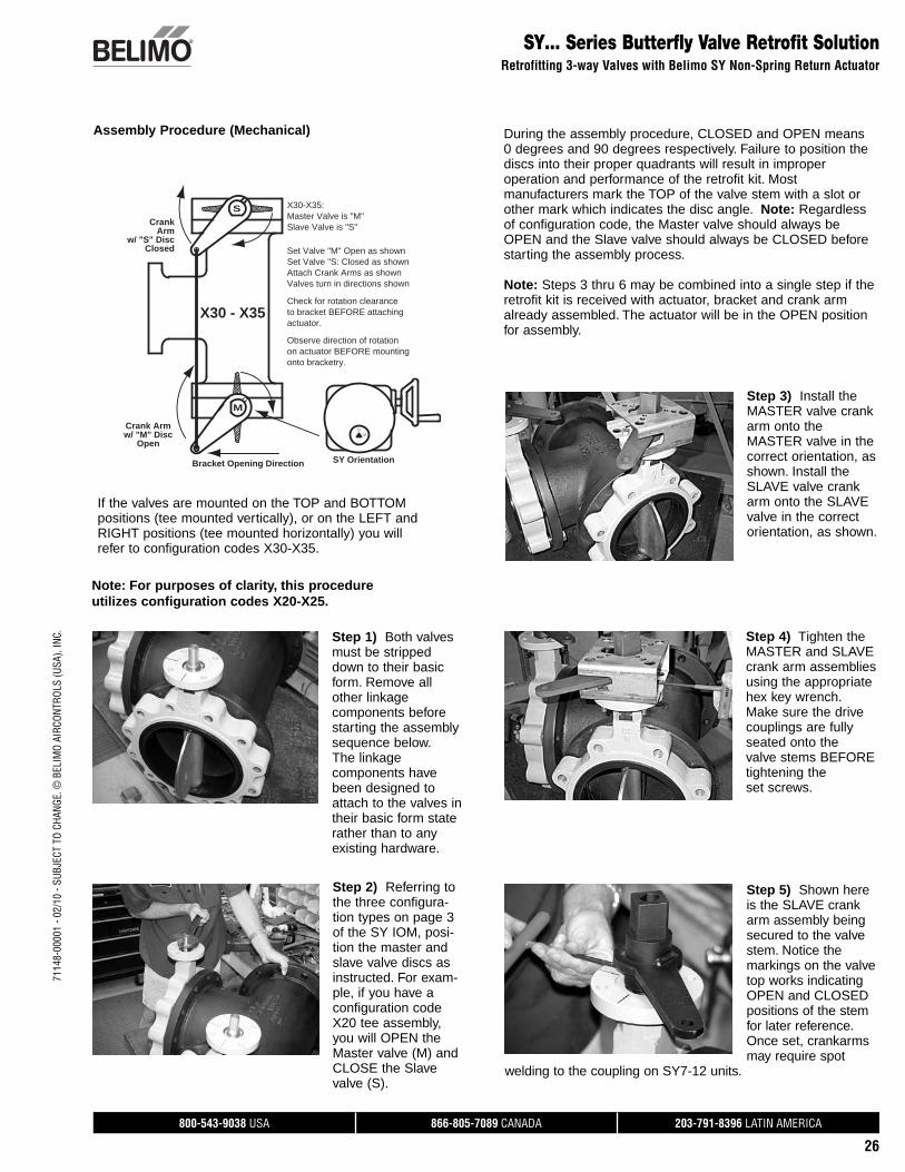
Step 1) Both valves must be stripped down to their basic form. Remove all other linkage components before starting the assembly sequence below. The linkage components have been designed to attach to the valves in their basic form state rather than to any existing hardware.
Step 2) Referring to the three configura-tion types on page 3 of the SY IOM, posi-tion the master and slave valve discs as instructed. For exam-ple, if you have a configuration code X20 tee assembly, you will OPEN the Master valve (M) and CLOSE the Slave valve (S).
Note: For purposes of clarity, this procedure utilizes configuration codes X20-X25.
Step 3) Install the MASTER valve crank arm onto the MASTER valve in the correct orientation, as shown. Install the SLAVE valve crank arm onto the SLAVE valve in the correct orientation, as shown.
Step 4) Tighten the MASTER and SLAVE crank arm assemblies using the appropriate hex key wrench. Make sure the drive couplings are fully seated onto the valve stems BEFORE tightening the set screws.
Step 5) Shown here is the SLAVE crank arm assembly being secured to the valve stem. Notice the markings on the valve top works indicating OPEN and CLOSED positions of the stem for later reference. Once set, crankarms may require spot
welding to the coupling on SY7-12 units.
During the assembly procedure, CLOSED and OPEN means 0 degrees and 90 degrees respectively. Failure to position the discs into their proper quadrants will result in improper operation and performance of the retrofit kit. Most manufacturers mark the TOP of the valve stem with a slot or other mark which indicates the disc angle. Note: Regardless of configuration code, the Master valve should always be OPEN and the Slave valve should always be CLOSED before starting the assembly process.
Note: Steps 3 thru 6 may be combined into a single step if the retrofit kit is received with actuator, bracket and crank arm already assembled. The actuator will be in the OPEN position for assembly.
Assembly Procedure (Mechanical)
800-543-9038 USA 866-805-7089 CANADA 203-791-8396 LATIN AMERICA
27
7114
8-00
001
- 02/
10 -
SUBJ
ECT
TO C
HANG
E. ©
BEL
IMO
AIRC
ONTR
OLS
(USA
), IN
C.
SY… Series Butterfly Valve Retrofit SolutionRetrofitting 3-way Valves with Belimo SY Non-Spring Return Actuator
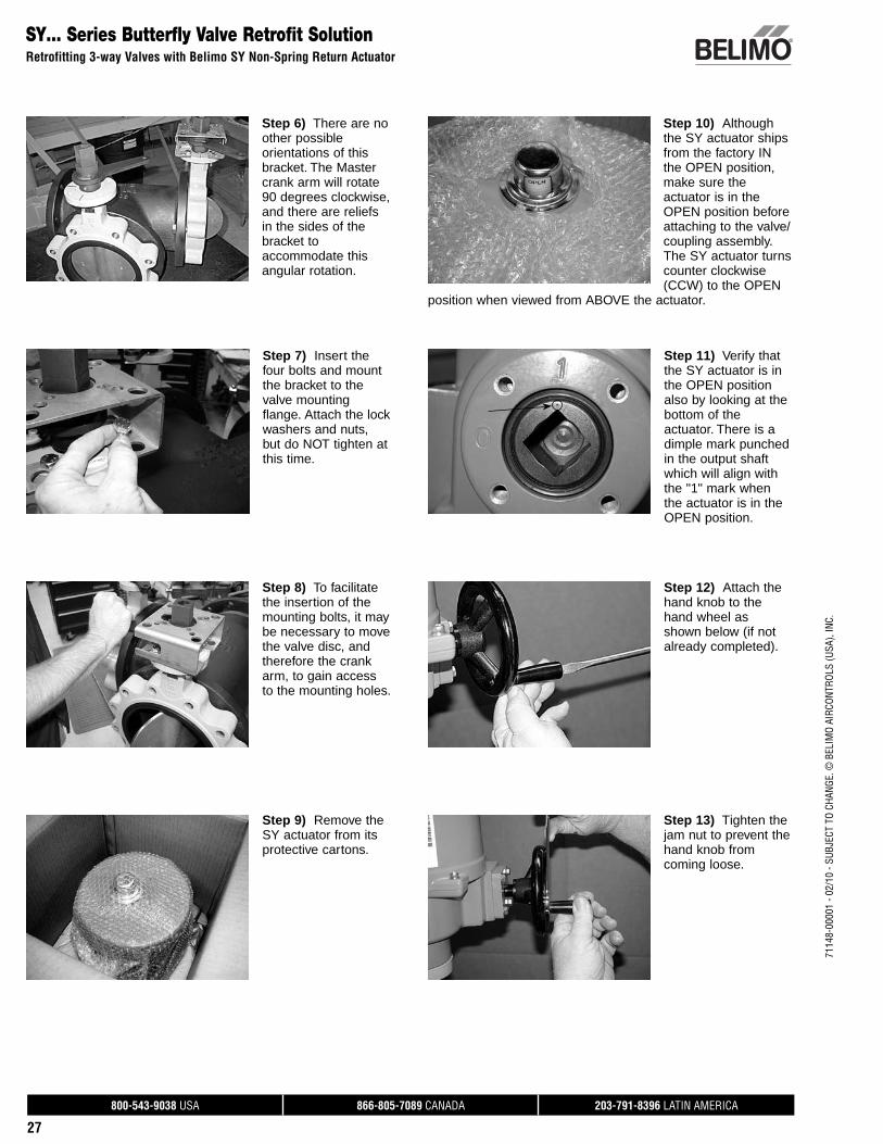
Step 6) There are no other possible orientations of this bracket. The Master crank arm will rotate 90 degrees clockwise, and there are reliefs in the sides of the bracket to accommodate this angular rotation.
Step 7) Insert the four bolts and mount the bracket to the valve mounting flange. Attach the lock washers and nuts, but do NOT tighten at this time.
Step 8) To facilitate the insertion of the mounting bolts, it may be necessary to move the valve disc, and therefore the crank arm, to gain access to the mounting holes.
Step 9) Remove the SY actuator from its protective cartons.
Step 10) Although the SY actuator ships from the factory IN the OPEN position, make sure the actuator is in the OPEN position before attaching to the valve/coupling assembly. The SY actuator turns counter clockwise (CCW) to the OPEN
position when viewed from ABOVE the actuator.
Step 11) Verify that the SY actuator is in the OPEN position also by looking at the bottom of the actuator. There is a dimple mark punched in the output shaft which will align with the "1" mark when the actuator is in the OPEN position.
Step 12) Attach the hand knob to the hand wheel as shown below (if not already completed).
Step 13) Tighten the jam nut to prevent the hand knob from coming loose.
800-543-9038 USA 866-805-7089 CANADA 203-791-8396 LATIN AMERICA
28
7114
8-00
001
- 02/
10 -
SUBJ
ECT
TO C
HANG
E. ©
BEL
IMO
AIRC
ONTR
OLS
(USA
), IN
C.SY… Series Butterfly Valve Retrofit Solution
Retrofitting 3-way Valves with Belimo SY Non-Spring Return Actuator
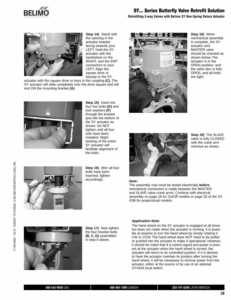
Step 14) Stand with the opening in the actuator bracket facing towards your LEFT. Hold the SY actuator with the handwheel on the RIGHT, and the EMT connectors to your LEFT. Align the square drive or keyway in the SY
actuator with the square drive or keys in the coupling (C). The SY actuator will slide completely over the drive square and will rest ON the mounting bracket (A).
Step 15) Insert the four hex bolts (G) and lock washers (F) through the bracket and into the bottom of the SY actuator as shown. Do NOT tighten until all four sets have been installed. Slight twisting of the entire SY actuator will facilitate alignment of the bolts.
Step 16) After all four bolts have been inserted, tighten accordingly.
Step 17) Now tighten the four bracket bolts (B, C, D) assembled in step 6 above.
Step 18) When mechanical assembly is complete, the SY actuator and MASTER valve should be oriented as shown below. The actuator is in the OPEN position, and the valve disc is fully OPEN, and all bolts are tight.
Step 19) The SLAVE valve is fully CLOSED with the crank arm oriented as shown.
Note:The assembly now must be tested electrically before mechanical connection is made between the MASTER and SLAVE valve crank arms. Continue with electrical assembly on page 18 for On/Off models or page 20 of the SY IOM for proportional models.
Application Note: The hand wheel on the SY actuator is engaged at all times but does not rotate when the actuator is running. It is possi-ble at anytime to turn the hand wheel by simply rotating it CW or CCW. The hand wheel does NOT need to be pulled or pushed into the actuator to make it operational. However, it should be noted that if a control signal and power is pres-ent at the actuator when the hand wheel is turned, the actuator will return to its controlled position. If it is desired to have the actuator maintain its position after turning the hand wheel, it will be necessary to remove power from the actuator, either at the source or by use of an optional SY-HOA local switch.
800-543-9038 USA 866-805-7089 CANADA 203-791-8396 LATIN AMERICA
29
7114
8-00
001
- 02/
10 -
SUBJ
ECT
TO C
HANG
E. ©
BEL
IMO
AIRC
ONTR
OLS
(USA
), IN
C.
SY… Series Butterfly Valve Retrofit SolutionRetrofitting 3-way Valves with Belimo SY On/Off Non-Spring Return Actuator
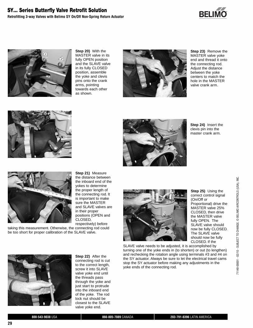
Step 21) Measure the distance between the inboard end of the yokes to determine the proper length of the connecting rod. It is important to make sure the MASTER and SLAVE valves are in their proper positions (OPEN and CLOSED, respectively) before
taking this measurement. Otherwise, the connecting rod could be too short for proper calibration of the SLAVE valve.
Step 25) Using the correct control signal (On/Off or Proportional) drive the MASTER valve 25% CLOSED, then drive the MASTER valve fully OPEN. The SLAVE valve should now be fully CLOSED. The SLAVE valve should now be fully CLOSED. If the
SLAVE valve needs to be adjusted, it is accomplished by turning one of the yoke ends in (to shorten) or out (to lengthen) and rechecking the rotation angle using terminals #3 and #4 on the SY actuator. Always be sure to let the electrical travel cams stop the SY actuator before making any adjustments in the yoke ends of the connecting rod.
Step 22) After the connecting rod is cut to the correct length, screw it into SLAVE valve yoke end until the threads pass through the yoke and just start to protrude into the inboard end of the yoke. The rod lock nut should be closest to the SLAVE valve yoke end.
Step 23) Remove the MASTER valve yoke end and thread it onto the connecting rod. Adjust the distance between the yoke centers to match the hole in the MASTER valve crank arm.
Step 24) Insert the clevis pin into the master crank arm.
Step 20) With the MASTER valve in its fully OPEN position and the SLAVE valve in its fully CLOSED position, assemble the yoke and clevis pins onto the crank arms, pointing towards each other as shown.
800-543-9038 USA 866-805-7089 CANADA 203-791-8396 LATIN AMERICA
30
7114
8-00
001
- 02/
10 -
SUBJ
ECT
TO C
HANG
E. ©
BEL
IMO
AIRC
ONTR
OLS
(USA
), IN
C.
Step 28) Replace the cover on the SY actuator and secure the four cover screws. One final check to make sure all bolts, screws, nuts & setscrews are tight.
Step 29) The mechanical and electrical installation of your retrofit system is now complete.
END PROCEDURE
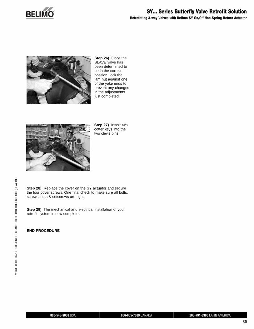
Step 26) Once the SLAVE valve has been determined to be in the correct position, lock the jam nut against one of the yoke ends to prevent any changes in the adjustments just completed.
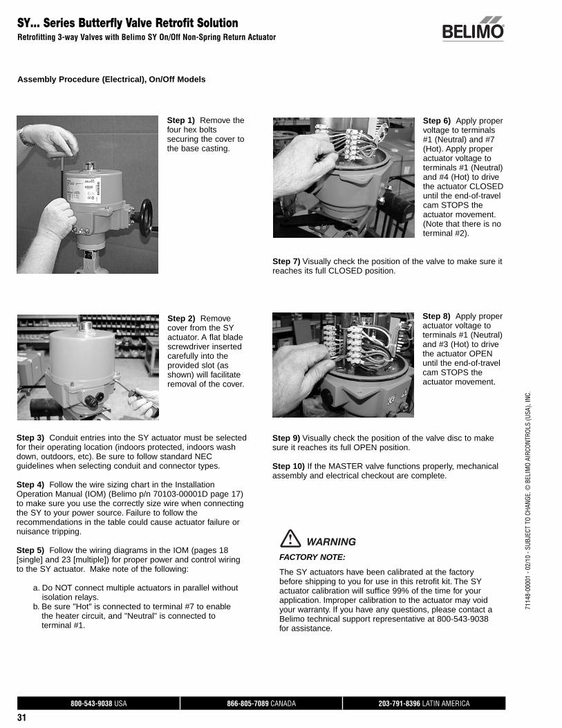
Step 27) Insert two cotter keys into the two clevis pins.
SY… Series Butterfly Valve Retrofit SolutionRetrofitting 3-way Valves with Belimo SY On/Off Non-Spring Return Actuator
800-543-9038 USA 866-805-7089 CANADA 203-791-8396 LATIN AMERICA
31
7114
8-00
001
- 02/
10 -
SUBJ
ECT
TO C
HANG
E. ©
BEL
IMO
AIRC
ONTR
OLS
(USA
), IN
C.
SY… Series Butterfly Valve Retrofit SolutionRetrofitting 3-way Valves with Belimo SY On/Off Non-Spring Return Actuator
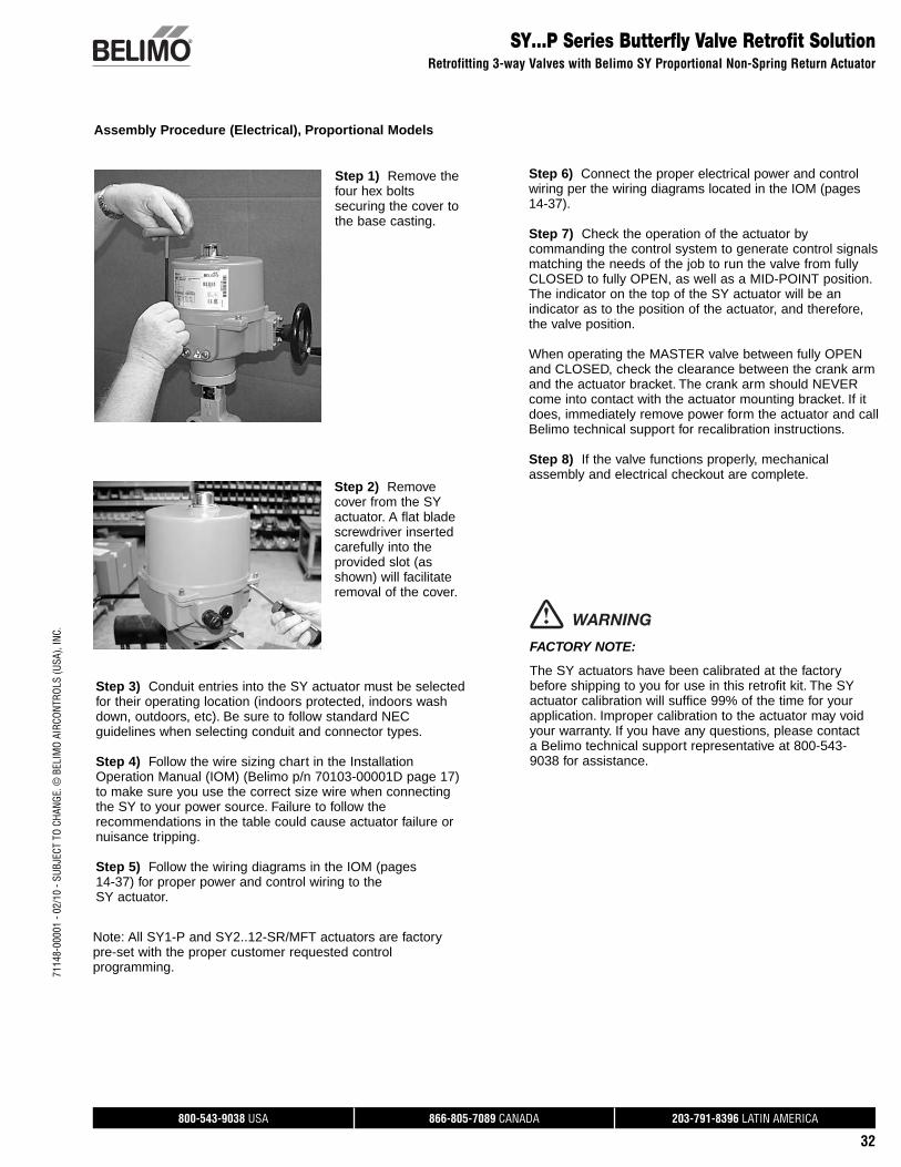
Step 1) Remove the four hex bolts securing the cover to the base casting.
Step 6) Apply proper voltage to terminals #1 (Neutral) and #7 (Hot). Apply proper actuator voltage to terminals #1 (Neutral) and #4 (Hot) to drive the actuator CLOSED until the end-of-travel cam STOPS the actuator movement. (Note that there is no terminal #2).
Step 7) Visually check the position of the valve to make sure it reaches its full CLOSED position.
Step 2) Remove cover from the SY actuator. A flat blade screwdriver inserted carefully into the provided slot (as shown) will facilitate removal of the cover.
Step 3) Conduit entries into the SY actuator must be selected for their operating location (indoors protected, indoors wash down, outdoors, etc). Be sure to follow standard NEC guidelines when selecting conduit and connector types.
Step 4) Follow the wire sizing chart in the Installation Operation Manual (IOM) (Belimo p/n 70103-00001D page 17) to make sure you use the correctly size wire when connecting the SY to your power source. Failure to follow the recommendations in the table could cause actuator failure or nuisance tripping.
Step 5) Follow the wiring diagrams in the IOM (pages 18 [single] and 23 [multiple]) for proper power and control wiring to the SY actuator. Make note of the following:
a. Do NOT connect multiple actuators in parallel without isolation relays.
b. Be sure "Hot" is connected to terminal #7 to enable the heater circuit, and "Neutral" is connected to terminal #1.
Step 8) Apply proper actuator voltage to terminals #1 (Neutral) and #3 (Hot) to drive the actuator OPEN until the end-of-travel cam STOPS the actuator movement.
Step 9) Visually check the position of the valve disc to make sure it reaches its full OPEN position.
Step 10) If the MASTER valve functions properly, mechanical assembly and electrical checkout are complete.
FACTORY NOTE:
The SY actuators have been calibrated at the factory before shipping to you for use in this retrofit kit. The SY actuator calibration will suffice 99% of the time for your application. Improper calibration to the actuator may void your warranty. If you have any questions, please contact a Belimo technical support representative at 800-543-9038 for assistance.
WARNING
Assembly Procedure (Electrical), On/Off Models
800-543-9038 USA 866-805-7089 CANADA 203-791-8396 LATIN AMERICA
32
7114
8-00
001
- 02/
10 -
SUBJ
ECT
TO C
HANG
E. ©
BEL
IMO
AIRC
ONTR
OLS
(USA
), IN
C.SY…P Series Butterfly Valve Retrofit Solution
Retrofitting 3-way Valves with Belimo SY Proportional Non-Spring Return Actuator
Step 1) Remove the four hex bolts securing the cover to the base casting.
Assembly Procedure (Electrical), Proportional Models
Step 2) Remove cover from the SY actuator. A flat blade screwdriver inserted carefully into the provided slot (as shown) will facilitate removal of the cover.
Step 3) Conduit entries into the SY actuator must be selected for their operating location (indoors protected, indoors wash down, outdoors, etc). Be sure to follow standard NEC guidelines when selecting conduit and connector types.
Step 4) Follow the wire sizing chart in the Installation Operation Manual (IOM) (Belimo p/n 70103-00001D page 17) to make sure you use the correct size wire when connecting the SY to your power source. Failure to follow the recommendations in the table could cause actuator failure or nuisance tripping.
Step 5) Follow the wiring diagrams in the IOM (pages 14-37) for proper power and control wiring to the SY actuator.
Step 6) Connect the proper electrical power and control wiring per the wiring diagrams located in the IOM (pages 14-37).
Step 7) Check the operation of the actuator by commanding the control system to generate control signals matching the needs of the job to run the valve from fully CLOSED to fully OPEN, as well as a MID-POINT position. The indicator on the top of the SY actuator will be an indicator as to the position of the actuator, and therefore, the valve position.
When operating the MASTER valve between fully OPEN and CLOSED, check the clearance between the crank arm and the actuator bracket. The crank arm should NEVER come into contact with the actuator mounting bracket. If it does, immediately remove power form the actuator and call Belimo technical support for recalibration instructions.
Step 8) If the valve functions properly, mechanical assembly and electrical checkout are complete.
FACTORY NOTE:
The SY actuators have been calibrated at the factory before shipping to you for use in this retrofit kit. The SY actuator calibration will suffice 99% of the time for your application. Improper calibration to the actuator may void your warranty. If you have any questions, please contact a Belimo technical support representative at 800-543-9038 for assistance.
WARNING
Note: All SY1-P and SY2..12-SR/MFT actuators are factory pre-set with the proper customer requested control programming.
800-543-9038 USA 866-805-7089 CANADA 203-791-8396 LATIN AMERICA
33
7114
8-00
001
- 02/
10 -
SUBJ
ECT
TO C
HANG
E. ©
BEL
IMO
AIRC
ONTR
OLS
(USA
), IN
C.
DRIVE SHAFT
ROLL PIN
BUSHING
NYLON WASHER
VALVE COUPLING
MOUNTINGBRACKET
NUT
LOCK WASHER
BOLT
ANTI-ROTATIONPIN
ACTUATOR PLATE
NUT
BOLT
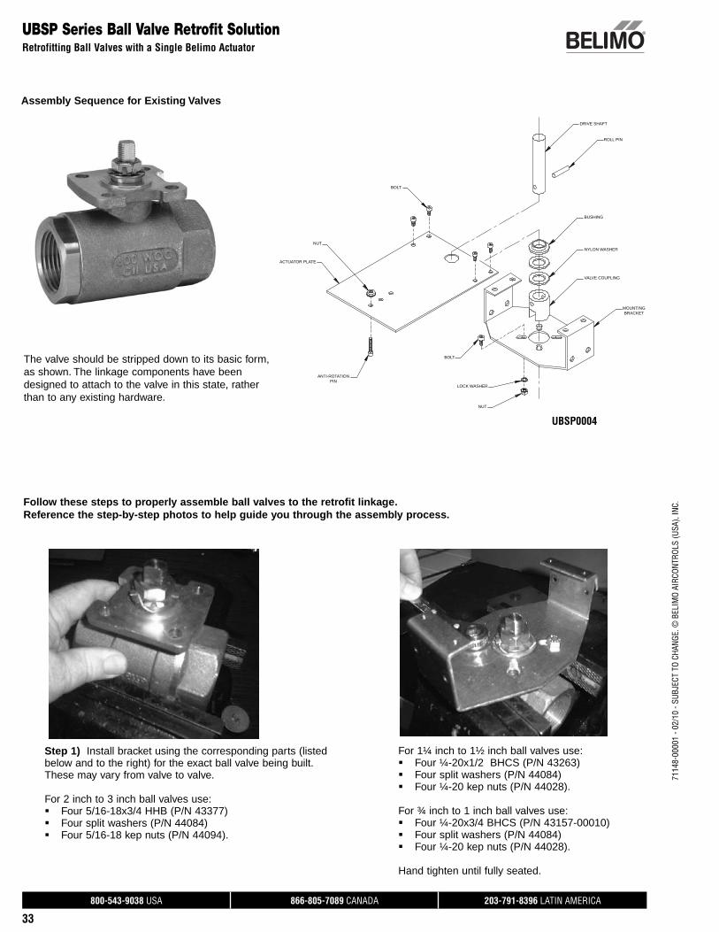
UBSP0004
UBSP Series Ball Valve Retrofit Solution Retrofitting Ball Valves with a Single Belimo Actuator
Step 1) Install bracket using the corresponding parts (listed below and to the right) for the exact ball valve being built. These may vary from valve to valve.
For 2 inch to 3 inch ball valves use:Four 5/16-18x3/4 HHB (P/N 43377) Four split washers (P/N 44084) Four 5/16-18 kep nuts (P/N 44094).
Follow these steps to properly assemble ball valves to the retrofit linkage. Reference the step-by-step photos to help guide you through the assembly process.
The valve should be stripped down to its basic form, as shown. The linkage components have been designed to attach to the valve in this state, rather than to any existing hardware.
For 1¼ inch to 1½ inch ball valves use:Four ¼-20x1/2 BHCS (P/N 43263)Four split washers (P/N 44084)Four ¼-20 kep nuts (P/N 44028). For ¾ inch to 1 inch ball valves use:Four ¼-20x3/4 BHCS (P/N 43157-00010)Four split washers (P/N 44084)Four ¼-20 kep nuts (P/N 44028).
Hand tighten until fully seated.
Assembly Sequence for Existing Valves
800-543-9038 USA 866-805-7089 CANADA 203-791-8396 LATIN AMERICA
34
7114
8-00
001
- 02/
10 -
SUBJ
ECT
TO C
HANG
E. ©
BEL
IMO
AIRC
ONTR
OLS
(USA
), IN
C.UBSP Series Ball Valve Retrofit Solution
Retrofitting Ball Valves with a Single Belimo Actuator
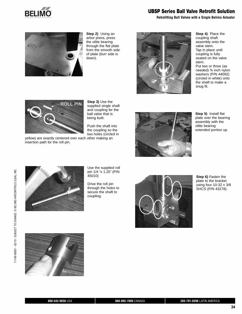
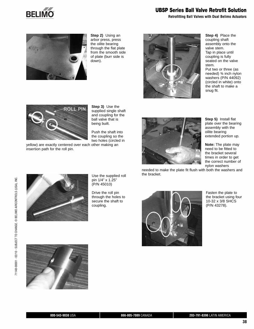
Step 2) Using an arbor press, press the oilite bearing through the flat plate from the smooth side of plate (burr side is down).
Step 3) Use the supplied single shaft and coupling for the ball valve that is being built.
Push the shaft into the coupling so the two holes (circled in
yellow) are exactly centered over each other making an insertion path for the roll pin.
Use the supplied roll pin 1/4 “x 1.25” (P/N 45010)
Drive the roll pin through the holes to secure the shaft to coupling.
Step 4) Place the coupling shaft assembly onto the valve stem. Tap in place until coupling is fully seated on the valve stem.Put two or three (as needed) ¾ inch nylon washers (P/N 44092) (circled in white) onto the shaft to make a snug fit.
Step 5) Install flat plate over the bearing assembly with the oilite bearing extended portion up.
Step 6) Fasten the plate to the bracket using four 10-32 x 3/8 SHCS (P/N 43278).
800-543-9038 USA 866-805-7089 CANADA 203-791-8396 LATIN AMERICA
35
7114
8-00
001
- 02/
10 -
SUBJ
ECT
TO C
HANG
E. ©
BEL
IMO
AIRC
ONTR
OLS
(USA
), IN
C.
UBSP Series Ball Valve Retrofit Solution Retrofitting Ball Valves with a Single Belimo Actuator
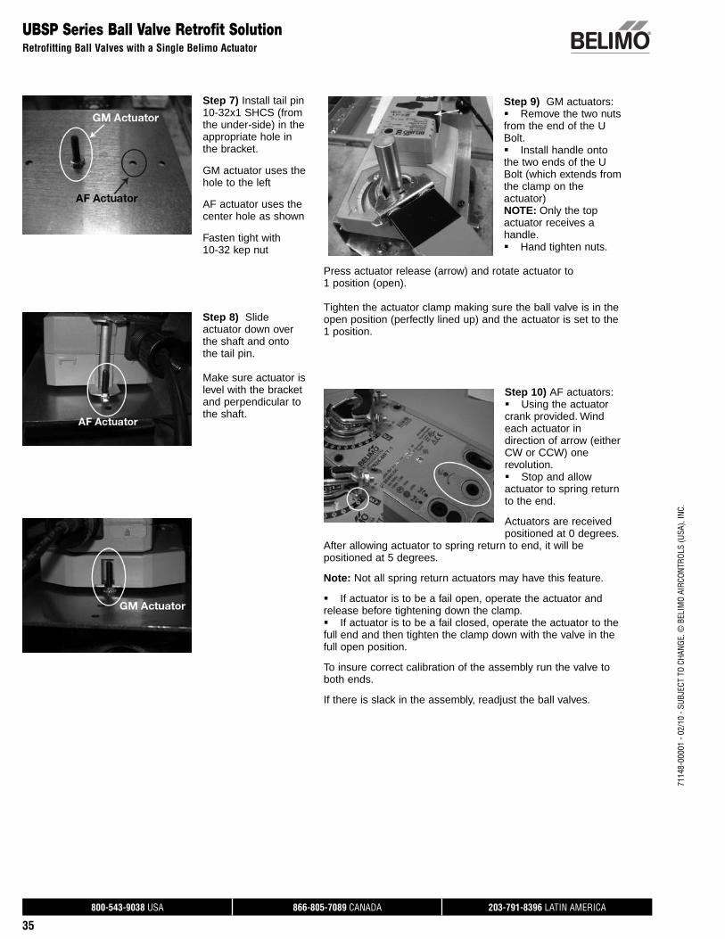
Step 7) Install tail pin 10-32x1 SHCS (from the under-side) in the appropriate hole in the bracket.
GM actuator uses the hole to the left
AF actuator uses the center hole as shown
Fasten tight with 10-32 kep nut
Step 8) Slide actuator down over the shaft and onto the tail pin.
Make sure actuator is level with the bracket and perpendicular to the shaft.
Step 9) GM actuators:Remove the two nuts from the end of the U Bolt. Install handle onto the two ends of the U Bolt (which extends from the clamp on the actuator)NOTE: Only the top actuator receives a handle.Hand tighten nuts.
Press actuator release (arrow) and rotate actuator to 1 position (open).
Tighten the actuator clamp making sure the ball valve is in the open position (perfectly lined up) and the actuator is set to the 1 position.
Step 10) AF actuators: Using the actuator crank provided. Wind each actuator in direction of arrow (either CW or CCW) one revolution.Stop and allow actuator to spring return to the end.
Actuators are received positioned at 0 degrees.
After allowing actuator to spring return to end, it will be positioned at 5 degrees.
Note: Not all spring return actuators may have this feature.
If actuator is to be a fail open, operate the actuator and release before tightening down the clamp. If actuator is to be a fail closed, operate the actuator to the full end and then tighten the clamp down with the valve in the full open position.
To insure correct calibration of the assembly run the valve to both ends.
If there is slack in the assembly, readjust the ball valves.
800-543-9038 USA 866-805-7089 CANADA 203-791-8396 LATIN AMERICA
36
7114
8-00
001
- 02/
10 -
SUBJ
ECT
TO C
HANG
E. ©
BEL
IMO
AIRC
ONTR
OLS
(USA
), IN
C.UBSP Series Ball Valve Retrofit Solution
Retrofitting Ball Valves with a Single Belimo Actuator
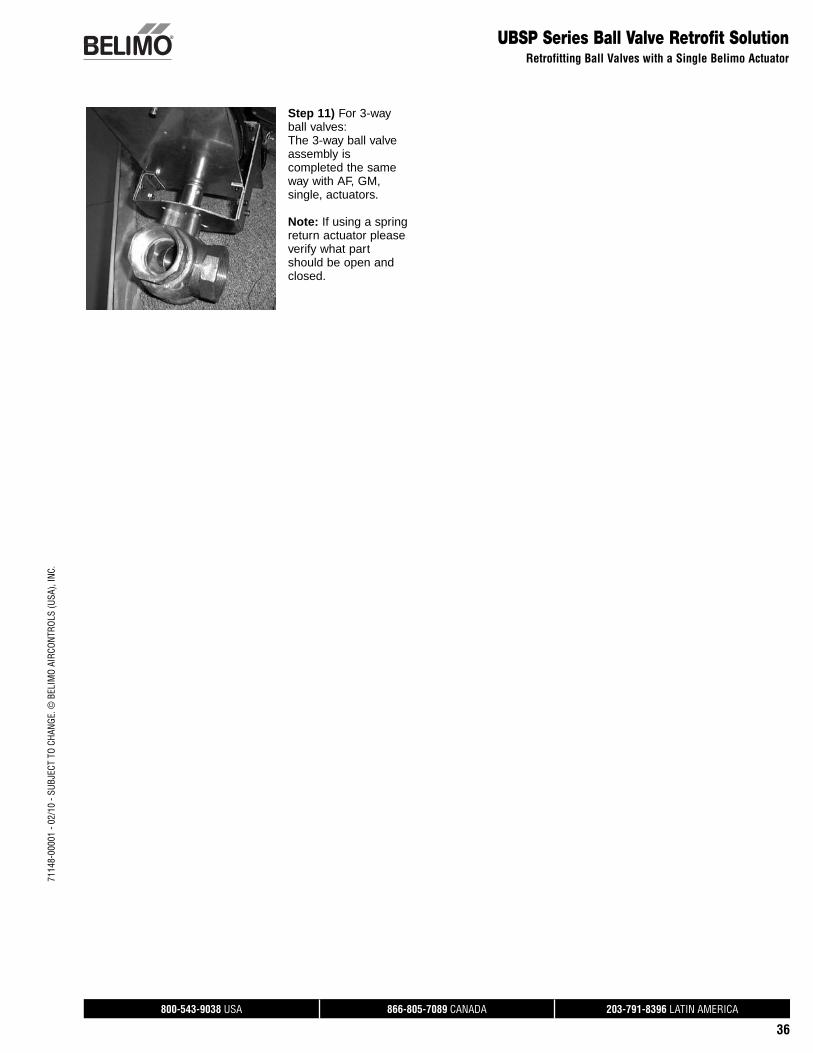
Step 11) For 3-way ball valves:The 3-way ball valve assembly is completed the same way with AF, GM, single, actuators.
Note: If using a spring return actuator please verify what part should be open and closed.
800-543-9038 USA 866-805-7089 CANADA 203-791-8396 LATIN AMERICA
37
7114
8-00
001
- 02/
10 -
SUBJ
ECT
TO C
HANG
E. ©
BEL
IMO
AIRC
ONTR
OLS
(USA
), IN
C.
UBSP Series Ball Valve Retrofit Solution Retrofitting Ball Valves with Dual Belimo Actuators
NUT
ANTI-ROTATION PIN
NUT
EXTENSION
EXTENSION
BOLT
BUSHING ACTUATOR PLATE
ROLL PIN
DRIVE SHAFT
BUSHING
NYLONWASHER
VALVE COUPLING
NUTNUT
LOCKWASHER
MOUNTINGBRACKET
BOLTANTI-ROTATION
PIN
NUT
ACTUATOR PLATE
BOLT
BOLT
UBSP0006
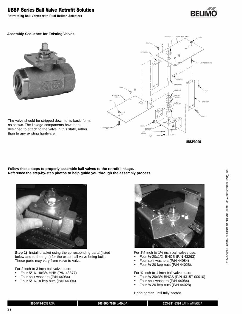
Step 1) Install bracket using the corresponding parts (listed below and to the right) for the exact ball valve being built. These parts may vary from valve to valve.
For 2 inch to 3 inch ball valves use:Four 5/16-18x3/4 HHB (P/N 43377) Four split washers (P/N 44084) Four 5/16-18 kep nuts (P/N 44094).
Follow these steps to properly assemble ball valves to the retrofit linkage. Reference the step-by-step photos to help guide you through the assembly process.
The valve should be stripped down to its basic form, as shown. The linkage components have been designed to attach to the valve in this state, rather than to any existing hardware.
For 1¼ inch to 1½ inch ball valves use:Four ¼-20x1/2 BHCS (P/N 43263)Four split washers (P/N 44084)Four ¼-20 kep nuts (P/N 44028). For ¾ inch to 1 inch ball valves use:Four ¼-20x3/4 BHCS (P/N 43157-00010)Four split washers (P/N 44084)Four ¼-20 kep nuts (P/N 44028).
Hand tighten until fully seated.
Assembly Sequence for Existing Valves
800-543-9038 USA 866-805-7089 CANADA 203-791-8396 LATIN AMERICA
38
7114
8-00
001
- 02/
10 -
SUBJ
ECT
TO C
HANG
E. ©
BEL
IMO
AIRC
ONTR
OLS
(USA
), IN
C.
UBSP Series Ball Valve Retrofit SolutionRetrofitting Ball Valves with Dual Belimo Actuators
Step 2) Using an arbor press, press the oilite bearing through the flat plate from the smooth side of plate (burr side is down).
Step 3) Use the supplied single shaft and coupling for the ball valve that is being built.
Push the shaft into the coupling so the two holes (circled in
yellow) are exactly centered over each other making an insertion path for the roll pin.
Use the supplied roll pin 1/4” x 1.25” (P/N 45010)
Drive the roll pin through the holes to secure the shaft to coupling.
Step 4) Place the coupling shaft assembly onto the valve stem. Tap in place until coupling is fully seated on the valve stem.Put two or three (as needed) ¾ inch nylon washers (P/N 44092) (circled in white) onto the shaft to make a snug fit.
Step 5) Install flat plate over the bearing assembly with the oilite bearing extended portion up.
Note: The plate may need to be fitted to the bracket several times in order to get the correct number of nylon washers
needed to make the plate fit flush with both the washers and the bracket.
Fasten the plate to the bracket using four 10-32 x 3/8 SHCS (P/N 43278).
800-543-9038 USA 866-805-7089 CANADA 203-791-8396 LATIN AMERICA
39
7114
8-00
001
- 02/
10 -
SUBJ
ECT
TO C
HANG
E. ©
BEL
IMO
AIRC
ONTR
OLS
(USA
), IN
C.
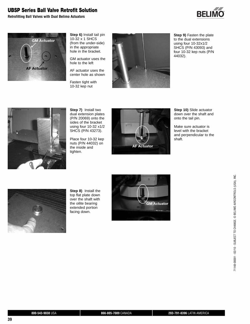
Step 8) Install the top flat plate down over the shaft with the oilite bearing extended portion facing down.
UBSP Series Ball Valve Retrofit Solution Retrofitting Ball Valves with Dual Belimo Actuators
Step 6) Install tail pin 10-32 x 1 SHCS (from the under-side) in the appropriate hole in the bracket.
GM actuator uses the hole to the left
AF actuator uses the center hole as shown
Fasten tight with 10-32 kep nut
Step 7) Install two dual extension plates (P/N 20069) onto the sides of the bracket using four 10-32 x1/2 SHCS (P/N 43273).
Place four 10-32 kep nuts (P/N 44032) on the inside and tighten.
Step 9) Fasten the plate to the dual extensions using four 10-32x1/2 SHCS (P/N 43093) and four 10-32 kep nuts (P/N 44032).
Step 10) Slide actuator down over the shaft and onto the tail pin.
Make sure actuator is level with the bracket and perpendicular to the shaft.
800-543-9038 USA 866-805-7089 CANADA 203-791-8396 LATIN AMERICA
40
7114
8-00
001
- 02/
10 -
SUBJ
ECT
TO C
HANG
E. ©
BEL
IMO
AIRC
ONTR
OLS
(USA
), IN
C.
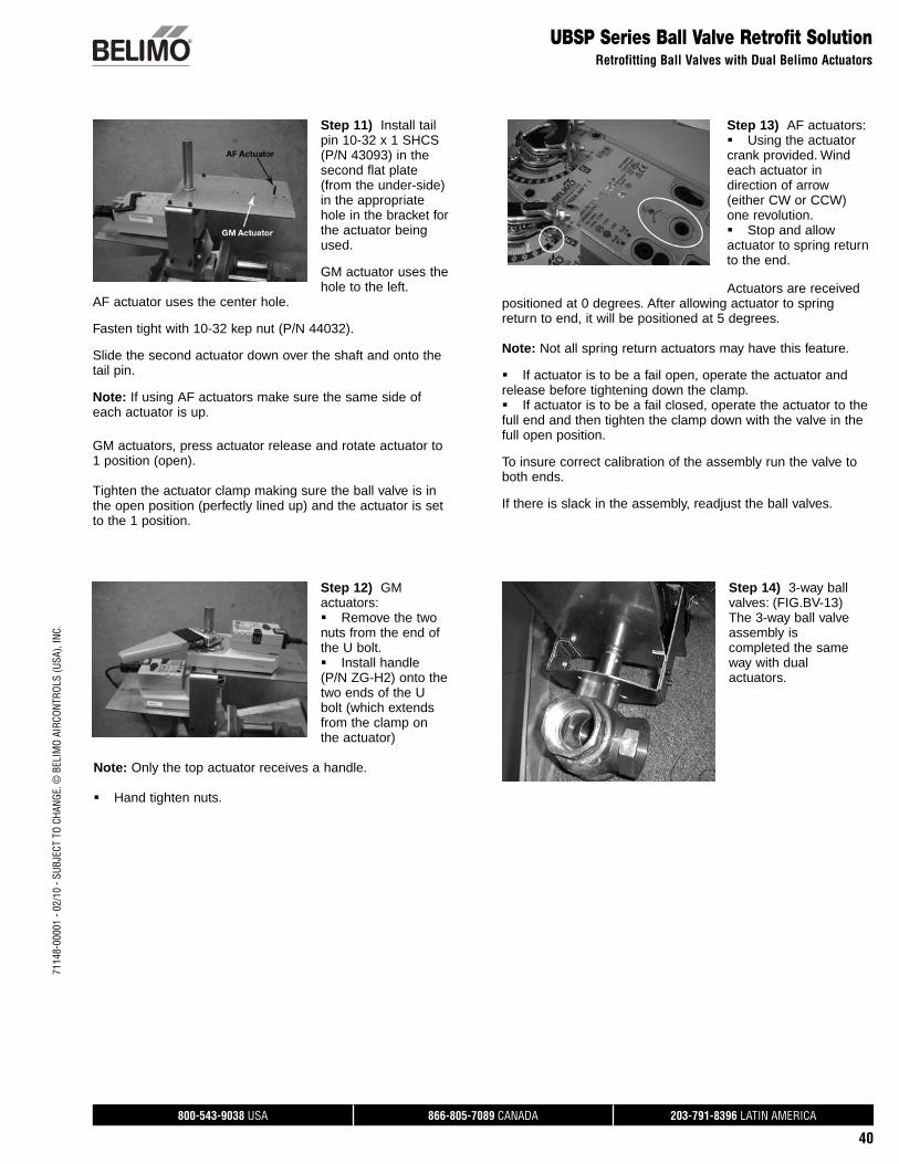
Step 14) 3-way ball valves: (FIG.BV-13) The 3-way ball valve assembly is completed the same way with dual actuators.
Step 11) Install tail pin 10-32 x 1 SHCS (P/N 43093) in the second flat plate (from the under-side) in the appropriate hole in the bracket for the actuator being used.
GM actuator uses the hole to the left.
AF actuator uses the center hole. Fasten tight with 10-32 kep nut (P/N 44032).
Slide the second actuator down over the shaft and onto the tail pin.
Note: If using AF actuators make sure the same side of each actuator is up.
GM actuators, press actuator release and rotate actuator to 1 position (open).
Tighten the actuator clamp making sure the ball valve is in the open position (perfectly lined up) and the actuator is set to the 1 position.
Step 13) AF actuators: Using the actuator crank provided. Wind each actuator in direction of arrow (either CW or CCW) one revolution.Stop and allow actuator to spring return to the end.
Actuators are received positioned at 0 degrees. After allowing actuator to spring return to end, it will be positioned at 5 degrees.
Note: Not all spring return actuators may have this feature.
If actuator is to be a fail open, operate the actuator and release before tightening down the clamp. If actuator is to be a fail closed, operate the actuator to the full end and then tighten the clamp down with the valve in the full open position.
To insure correct calibration of the assembly run the valve to both ends.
If there is slack in the assembly, readjust the ball valves.
UBSP Series Ball Valve Retrofit SolutionRetrofitting Ball Valves with Dual Belimo Actuators
Step 12) GM actuators:Remove the two nuts from the end of the U bolt. Install handle (P/N ZG-H2) onto the two ends of the U bolt (which extends from the clamp on the actuator)
Note: Only the top actuator receives a handle.
Hand tighten nuts.

BELIMO AmericasUSA Locations, 43 Old Ridgebury Road, Danbury, CT 06810Tel. 800-543-9038, Fax 800-228-8283, [email protected]
1049 Fortunado Loop, Sparks, NV 89436Tel. 800 987-9042, Fax 800-987-8875, [email protected]
Canada Locations, 14/16 – 5716 Coopers Avenue, Mississauga, Ontario L4Z 2E8Tel. 866-805-7089, Fax 905-712-3124, [email protected]
Latin America Customer Service, Tel. 203-791-8396, Fax 203-791-9139, [email protected]
Belimo worldwide: www.belimo.com