Embed Size (px)
Citation preview
®
5
J207
21 -
06/
07 -
Sub
ject
to c
hang
e ©
Bel
imo
Airc
ontro
ls (U
SA),
Inc.
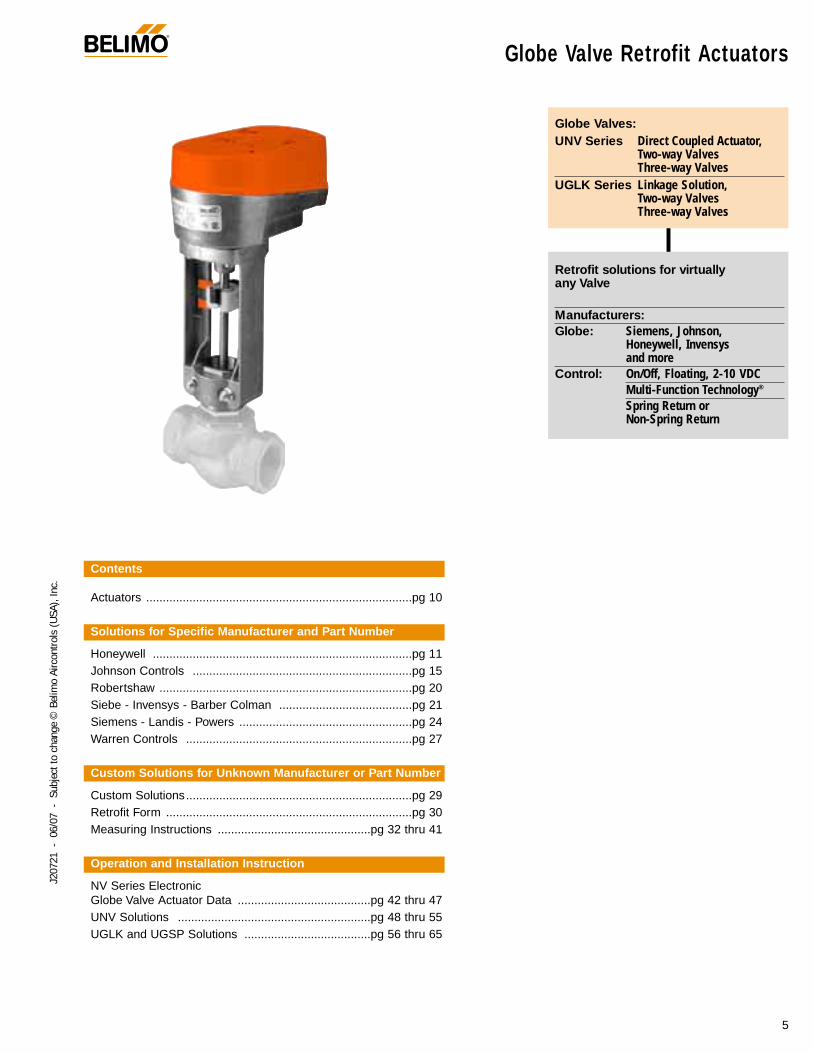
Globe Valves:UNV Series Direct Coupled Actuator,
Two-way Valves Three-way Valves
UGLK Series Linkage Solution,Two-way Valves Three-way Valves
Retrofit solutions for virtually any Valve
Manufacturers:Globe: Siemens, Johnson,
Honeywell, Invensys and more
Control: On/Off, Floating, 2-10 VDCMulti-Function Technology®
Spring Return or Non-Spring Return
Globe Valve Retrofit Actuators
Contents
Actuators ................................................................................pg 10
Solutions for Specific Manufacturer and Part Number
Honeywell ..............................................................................pg 11Johnson Controls ..................................................................pg 15Robertshaw ............................................................................pg 20Siebe - Invensys - Barber Colman ........................................pg 21Siemens - Landis - Powers ....................................................pg 24Warren Controls ....................................................................pg 27
Custom Solutions for Unknown Manufacturer or Part Number
Custom Solutions....................................................................pg 29Retrofit Form ..........................................................................pg 30Measuring Instructions ..............................................pg 32 thru 41
Operation and Installation Instruction
NV Series Electronic Globe Valve Actuator Data ........................................pg 42 thru 47UNV Solutions ..........................................................pg 48 thru 55UGLK and UGSP Solutions ......................................pg 56 thru 65
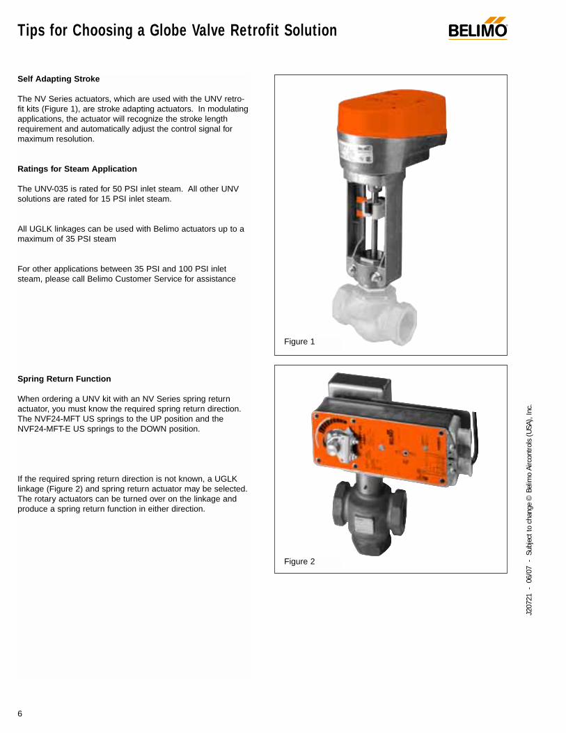
Self Adapting Stroke
The NV Series actuators, which are used with the UNV retro-fit kits (Figure 1), are stroke adapting actuators. In modulatingapplications, the actuator will recognize the stroke lengthrequirement and automatically adjust the control signal formaximum resolution.
Ratings for Steam Application
The UNV-035 is rated for 50 PSI inlet steam. All other UNVsolutions are rated for 15 PSI inlet steam.
All UGLK linkages can be used with Belimo actuators up to amaximum of 35 PSI steam
For other applications between 35 PSI and 100 PSI inletsteam, please call Belimo Customer Service for assistance
Spring Return Function
When ordering a UNV kit with an NV Series spring returnactuator, you must know the required spring return direction.The NVF24-MFT US springs to the UP position and theNVF24-MFT-E US springs to the DOWN position.
If the required spring return direction is not known, a UGLKlinkage (Figure 2) and spring return actuator may be selected.The rotary actuators can be turned over on the linkage andproduce a spring return function in either direction.
Tips for Choosing a Globe Valve Retrofit Solution ®
6
J207
21 -
06/
07 -
Sub
ject
to c
hang
e ©
Bel
imo
Airc
ontro
ls (U
SA),
Inc.
Figure 2
Figure 1
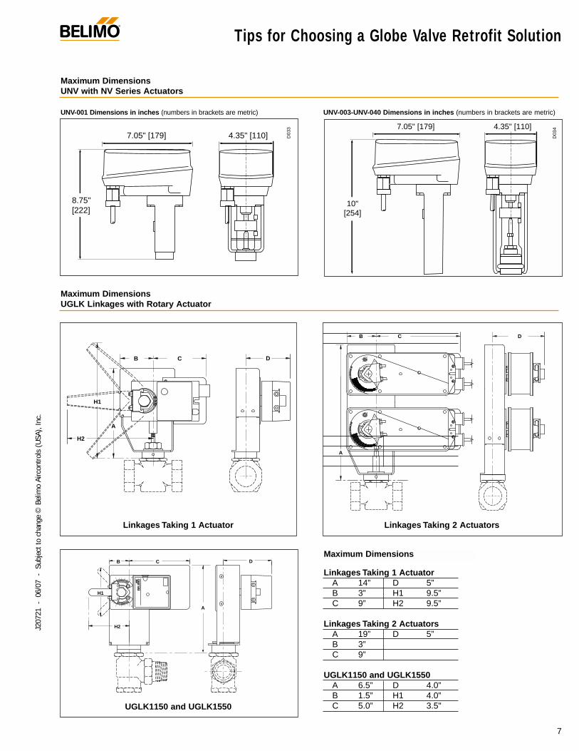
Linkages Taking 1 ActuatorA 14” D 5”B 3” H1 9.5”C 9” H2 9.5”
Linkages Taking 2 ActuatorsA 19” D 5”B 3”C 9”
UGLK1150 and UGLK1550A 6.5” D 4.0”B 1.5” H1 4.0”C 5.0” H2 3.5"
Linkages Taking 1 Actuator
UGLK1150 and UGLK1550
Linkages Taking 2 Actuators
Tips for Choosing a Globe Valve Retrofit Solution®
7
J207
21 -
06/
07 -
Sub
ject
to c
hang
e ©
Bel
imo
Airc
ontro
ls (U
SA),
Inc.
UNV-001 Dimensions in inches (numbers in brackets are metric) UNV-003-UNV-040 Dimensions in inches (numbers in brackets are metric)
8.75" [222]
7.05" [179] 4.35" [110]
10" [254]
7.05" [179] 4.35" [110]
D03
3
D03
4
Maximum DimensionsUNV with NV Series Actuators
Maximum DimensionsUGLK Linkages with Rotary Actuator
A
B C
H2
H1
D
01
A
B C
H1
H2
D
A
RL
L
B
R
C D
Maximum Dimensions
How to use the Globe Valve Retrofit Guide ®
8
J207
21 -
06/
07 -
Sub
ject
to c
hang
e ©
Bel
imo
Airc
ontro
ls (U
SA),
Inc.
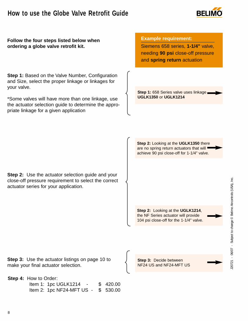
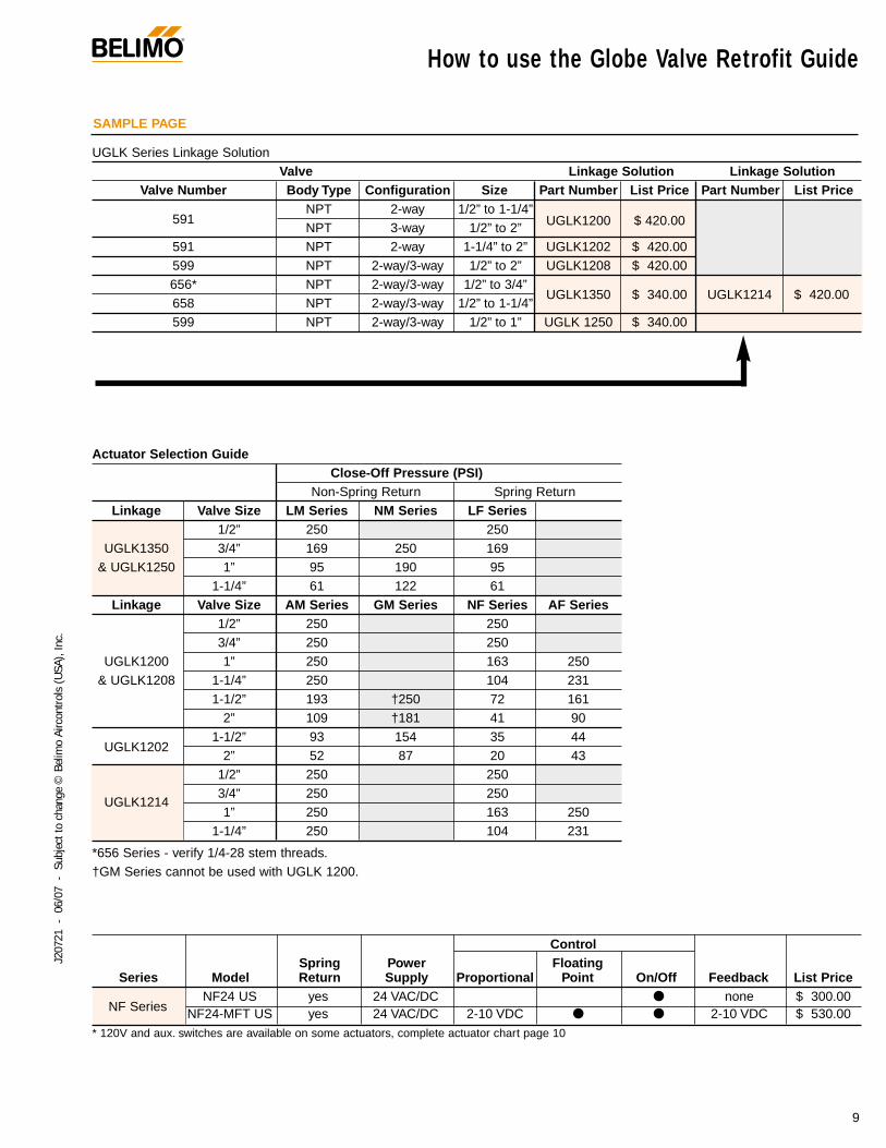
Follow the four steps listed below when ordering a globe valve retrofit kit.
Step 1: Based on the Valve Number, Configurationand Size, select the proper linkage or linkages foryour valve.
*Some valves will have more than one linkage, usethe actuator selection guide to determine the appro-priate linkage for a given application
Step 2: Use the actuator selection guide and yourclose-off pressure requirement to select the correctactuator series for your application.
Step 3: Use the actuator listings on page 10 tomake your final actuator selection.
Example requirement:
Siemens 658 series, 1-1/4" valve,needing 90 psi close-off pressureand spring return actuation
Step 1: 658 Series valve uses linkageUGLK1350 or UGLK1214
Step 2: Looking at the UGLK1214,the NF Series actuator will provide104 psi close-off for the 1-1/4" valve.
Step 3: Decide between NF24 US and NF24-MFT US
Step 2: Looking at the UGLK1350 thereare no spring return actuators that willachieve 90 psi close-off for 1-1/4" valve.
Step 4: How to Order:Item 1: 1pc UGLK1214 - $ 420.00Item 2: 1pc NF24-MFT US - $ 530.00
How to use the Globe Valve Retrofit Guide®
9
J207
21 -
06/
07 -
Sub
ject
to c
hang
e ©
Bel
imo
Airc
ontro
ls (U
SA),
Inc.
UGLK Series Linkage SolutionValve Linkage Solution Linkage Solution
Valve Number Body Type Configuration Size Part Number List Price Part Number List Price
591NPT 2-way 1/2” to 1-1/4”
UGLK1200 $ 420.00NPT 3-way 1/2” to 2”591 NPT 2-way 1-1/4” to 2” UGLK1202 $ 420.00599 NPT 2-way/3-way 1/2” to 2” UGLK1208 $ 420.00656* NPT 2-way/3-way 1/2” to 3/4”
UGLK1350 $ 340.00 UGLK1214 $ 420.00658 NPT 2-way/3-way 1/2” to 1-1/4”599 NPT 2-way/3-way 1/2” to 1” UGLK 1250 $ 340.00
Actuator Selection GuideClose-Off Pressure (PSI)
Non-Spring Return Spring ReturnLinkage Valve Size LM Series NM Series LF Series
1/2” 250 250UGLK1350 3/4” 169 250 169
& UGLK1250 1” 95 190 951-1/4” 61 122 61
Linkage Valve Size AM Series GM Series NF Series AF Series1/2” 250 2503/4” 250 250
UGLK1200 1” 250 163 250& UGLK1208 1-1/4” 250 104 231
1-1/2” 193 †250 72 1612” 109 †181 41 90
UGLK12021-1/2” 93 154 35 44
2” 52 87 20 431/2” 250 250
UGLK12143/4” 250 2501” 250 163 250
1-1/4” 250 104 231
*656 Series - verify 1/4-28 stem threads.†GM Series cannot be used with UGLK 1200.
ControlSpring Power Floating
Series Model Return Supply Proportional Point On/Off Feedback List Price
NF SeriesNF24 US yes 24 VAC/DC none $ 300.00
NF24-MFT US yes 24 VAC/DC 2-10 VDC 2-10 VDC $ 530.00 * 120V and aux. switches are available on some actuators, complete actuator chart page 10
SAMPLE PAGE
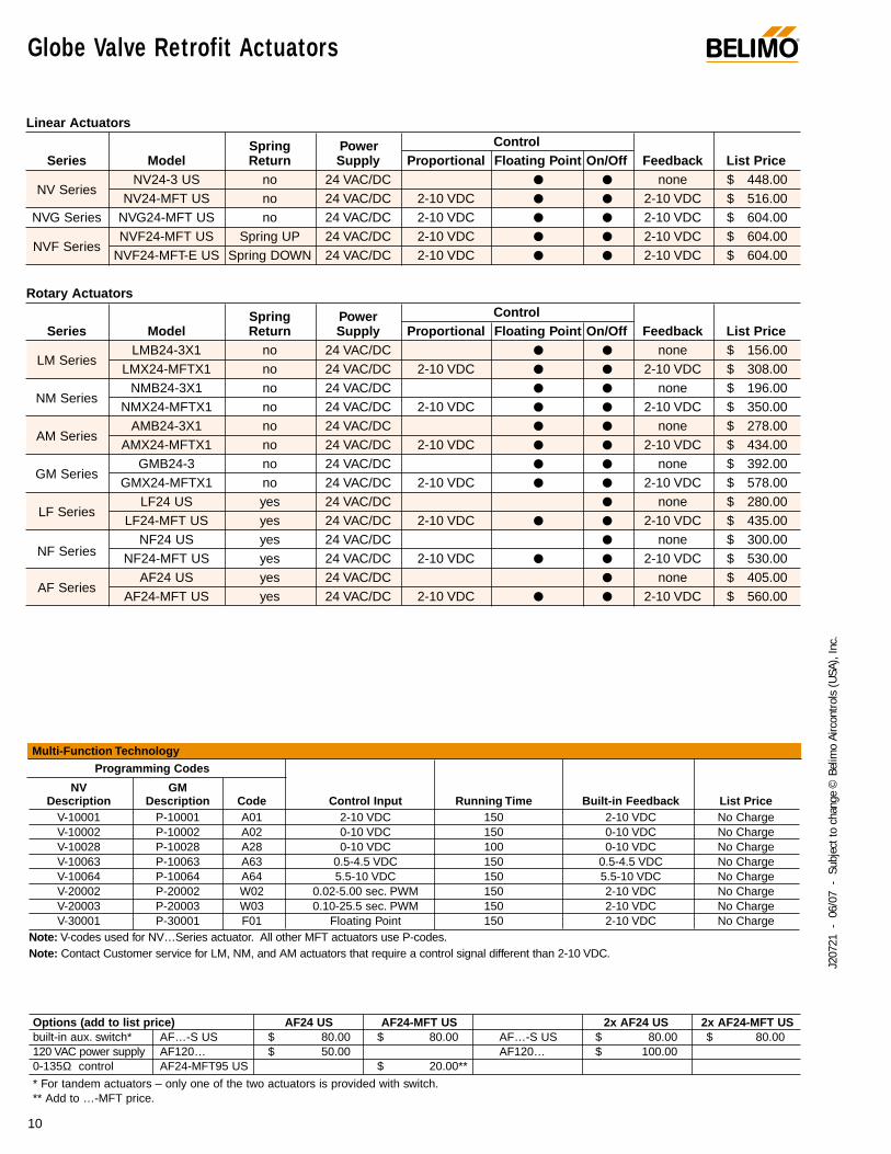
Linear Actuators
Spring Power ControlSeries Model Return Supply Proportional Floating Point On/Off Feedback List Price
NV SeriesNV24-3 US no 24 VAC/DC none $ 448.00
NV24-MFT US no 24 VAC/DC 2-10 VDC 2-10 VDC $ 516.00NVG Series NVG24-MFT US no 24 VAC/DC 2-10 VDC 2-10 VDC $ 604.00
NVF SeriesNVF24-MFT US Spring UP 24 VAC/DC 2-10 VDC 2-10 VDC $ 604.00
NVF24-MFT-E US Spring DOWN 24 VAC/DC 2-10 VDC 2-10 VDC $ 604.00
Rotary Actuators
Spring Power ControlSeries Model Return Supply Proportional Floating Point On/Off Feedback List Price
LM SeriesLMB24-3X1 no 24 VAC/DC none $ 156.00
LMX24-MFTX1 no 24 VAC/DC 2-10 VDC 2-10 VDC $ 308.00
NM SeriesNMB24-3X1 no 24 VAC/DC none $ 196.00
NMX24-MFTX1 no 24 VAC/DC 2-10 VDC 2-10 VDC $ 350.00
AM SeriesAMB24-3X1 no 24 VAC/DC none $ 278.00
AMX24-MFTX1 no 24 VAC/DC 2-10 VDC 2-10 VDC $ 434.00
GM SeriesGMB24-3 no 24 VAC/DC none $ 392.00
GMX24-MFTX1 no 24 VAC/DC 2-10 VDC 2-10 VDC $ 578.00
LF SeriesLF24 US yes 24 VAC/DC none $ 280.00
LF24-MFT US yes 24 VAC/DC 2-10 VDC 2-10 VDC $ 435.00
NF SeriesNF24 US yes 24 VAC/DC none $ 300.00
NF24-MFT US yes 24 VAC/DC 2-10 VDC 2-10 VDC $ 530.00
AF SeriesAF24 US yes 24 VAC/DC none $ 405.00
AF24-MFT US yes 24 VAC/DC 2-10 VDC 2-10 VDC $ 560.00
®
10
J207
21 -
06/
07 -
Sub
ject
to c
hang
e ©
Bel
imo
Airc
ontro
ls (U
SA),
Inc.
Globe Valve Retrofit Actuators
Programming Codes
NV GM Description Description Code Control Input Running Time Built-in Feedback List Price
V-10001 P-10001 A01 2-10 VDC 150 2-10 VDC No ChargeV-10002 P-10002 A02 0-10 VDC 150 0-10 VDC No ChargeV-10028 P-10028 A28 0-10 VDC 100 0-10 VDC No ChargeV-10063 P-10063 A63 0.5-4.5 VDC 150 0.5-4.5 VDC No ChargeV-10064 P-10064 A64 5.5-10 VDC 150 5.5-10 VDC No ChargeV-20002 P-20002 W02 0.02-5.00 sec. PWM 150 2-10 VDC No ChargeV-20003 P-20003 W03 0.10-25.5 sec. PWM 150 2-10 VDC No ChargeV-30001 P-30001 F01 Floating Point 150 2-10 VDC No Charge
Note: V-codes used for NV…Series actuator. All other MFT actuators use P-codes.Note: Contact Customer service for LM, NM, and AM actuators that require a control signal different than 2-10 VDC.
Multi-Function Technology
Options (add to list price) AF24 US AF24-MFT US 2x AF24 US 2x AF24-MFT USbuilt-in aux. switch* AF…-S US $ 80.00 $ 80.00 AF…-S US $ 80.00 $ 80.00120 VAC power supply AF120… $ 50.00 AF120… $ 100.000-135Ω control AF24-MFT95 US $ 20.00**
* For tandem actuators – only one of the two actuators is provided with switch.** Add to …-MFT price.
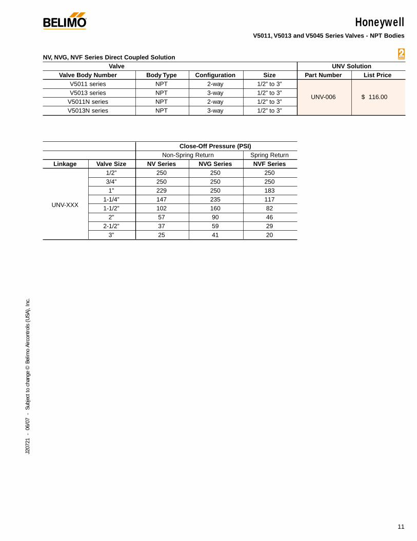
HoneywellV5011, V5013 and V5045 Series Valves - NPT Bodies
NV, NVG, NVF Series Direct Coupled SolutionValve UNV Solution
Valve Body Number Body Type Configuration Size Part Number List PriceV5011 series NPT 2-way 1/2” to 3”V5013 series NPT 3-way 1/2” to 3”
UNV-006 $ 116.00V5011N series NPT 2-way 1/2” to 3”V5013N series NPT 3-way 1/2” to 3”
Close-Off Pressure (PSI)Non-Spring Return Spring Return
Linkage Valve Size NV Series NVG Series NVF Series1/2” 250 250 2503/4” 250 250 2501” 229 250 183
UNV-XXX1-1/4” 147 235 1171-1/2” 102 160 82
2” 57 90 462-1/2” 37 59 29
3” 25 41 20
®
11
J207
21 -
06/
07 -
Sub
ject
to c
hang
e ©
Bel
imo
Airc
ontro
ls (U
SA),
Inc.
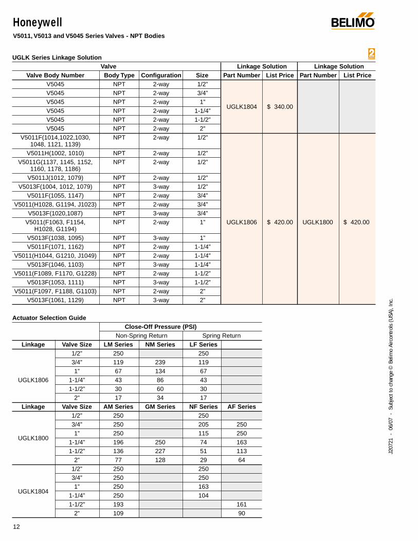
HoneywellV5011, V5013 and V5045 Series Valves - NPT Bodies
UGLK Series Linkage SolutionValve Linkage Solution Linkage Solution
Valve Body Number Body Type Configuration Size Part Number List Price Part Number List PriceV5045 NPT 2-way 1/2”V5045 NPT 2-way 3/4”V5045 NPT 2-way 1”
UGLK1804 $ 340.00V5045 NPT 2-way 1-1/4”V5045 NPT 2-way 1-1/2”V5045 NPT 2-way 2”
V5011F(1014,1022,1030, NPT 2-way 1/2”1048, 1121, 1139)
V5011H(1002, 1010) NPT 2-way 1/2”V5011G(1137, 1145, 1152, NPT 2-way 1/2”
1160, 1178, 1186)V5011J(1012, 1079) NPT 2-way 1/2”
V5013F(1004, 1012, 1079) NPT 3-way 1/2”V5011F(1055, 1147) NPT 2-way 3/4”
V5011(H1028, G1194, J1023) NPT 2-way 3/4”V5013F(1020,1087) NPT 3-way 3/4”
V5011(F1063, F1154, NPT 2-way 1” UGLK1806 $ 420.00 UGLK1800 $ 420.00 H1028, G1194)
V5013F(1038, 1095) NPT 3-way 1”V5011F(1071, 1162) NPT 2-way 1-1/4”
V5011(H1044, G1210, J1049) NPT 2-way 1-1/4”V5013F(1046, 1103) NPT 3-way 1-1/4”
V5011(F1089, F1170, G1228) NPT 2-way 1-1/2”V5013F(1053, 1111) NPT 3-way 1-1/2”
V5011(F1097, F1188, G1103) NPT 2-way 2”V5013F(1061, 1129) NPT 3-way 2”
Actuator Selection GuideClose-Off Pressure (PSI)
Non-Spring Return Spring ReturnLinkage Valve Size LM Series NM Series LF Series
1/2” 250 2503/4” 119 239 1191” 67 134 67
UGLK1806 1-1/4” 43 86 431-1/2” 30 60 30
2” 17 34 17Linkage Valve Size AM Series GM Series NF Series AF Series
1/2” 250 2503/4” 250 205 250
UGLK18001” 250 115 250
1-1/4” 196 250 74 1631-1/2” 136 227 51 113
2” 77 128 29 641/2” 250 2503/4” 250 250
UGLK18041” 250 163
1-1/4” 250 1041-1/2” 193 161
2” 109 90
®
12
J207
21 -
06/
07 -
Sub
ject
to c
hang
e ©
Bel
imo
Airc
ontro
ls (U
SA),
Inc.
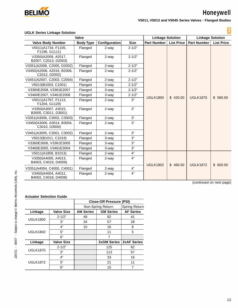
HoneywellV5011, V5013 and V5045 Series Valves - Flanged Bodies
UGLK Series Linkage SolutionValve Linkage Solution Linkage Solution
Valve Body Number Body Type Configuration Size Part Number List Price Part Number List PriceV5011(A1734, F1105, Flanged 2-way 2-1/2”
F1196, G1111)V3350(A2009, A2017, Flanged 2-way 2-1/2”B2007, C2013, D2003)
V3351(A2008, C2005, D2002) Flanged 2-way 2-1/2”V3450(A2008, A2016, B2006, Flanged 2-way 2-1/2”
C2012, D2002)V3451(A2007, C2003, C2004) Flanged 2-way 2-1/2”
V5013(B1003, C1001) Flanged 3-way 2-1/2”V3360E2008, V3361E2007 Flanged 3-way 2-1/2”V3460E2007, V3461E2006 Flanged 3-way 2-1/2”
UGLK1800 $ 420.00 UGLK1870 $ 580.00V5011(A1767, F1113, Flanged 2-way 3”
F1204, G1129)V3350(A3007, A3015, Flanged 2-way 3”B3005, C3011, D3001)
V3351(A3006, C3002, C3003) Flanged 2-way 3”V3450(A3006, A3014, B3004, Flanged 2-way 3”
C3010, D3000)
V3451(A3005, C3001, C3002) Flanged 2-way 3”V5013(B1011, C1019) Flanged 3-way 3”
V3360E3006, V3361E3005 Flanged 3-way 3”V3460E3005, V3461E3004 Flanged 3-way 3”
V5011(A1858, B1013) Flanged 2-way 4”V3350(A4005, A4013, Flanged 2-way 4”B4003, C4019, D4009)
UGLK1802 $ 460.00 UGLK1872 $ 600.00V3351(A4004, C4000, C4001) Flanged 2-way 4”
V3450(A4004, A4012, Flanged 2-way 4”B4002, C4018, D4008)
(continued on next page)
Actuator Selection GuideClose-Off Pressure (PSI)
Non-Spring Return Spring ReturnLinkage Valve Size AM Series GM Series AF Series
UGLK18002-1/2” 49 82 41
3” 34 57 284” 10 16 8
UGLK1802 5” 11 56” 7
Linkage Valve Size 2xGM Series 2xAF Series
UGLK18702-1/2” 125 82
3” 113 574” 33 16
UGLK1872 5” 21 116” 15 7
®
13
J207
21 -
06/
07 -
Sub
ject
to c
hang
e ©
Bel
imo
Airc
ontro
ls (U
SA),
Inc.
®
14
J207
21 -
06/
07 -
Sub
ject
to c
hang
e ©
Bel
imo
Airc
ontro
ls (U
SA),
Inc.
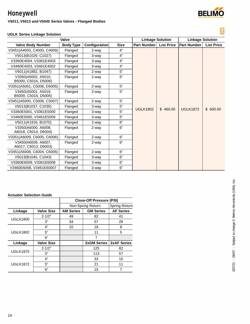
HoneywellV5011, V5013 and V5045 Series Valves - Flanged Bodies
UGLK Series Linkage SolutionValve Linkage Solution Linkage Solution
Valve Body Number Body Type Configuration Size Part Number List Price Part Number List PriceV3451(A4003, C4000, C4009) Flanged 2-way 4”
V5013(B1029, C1027) Flanged 3-way 4”V3360E4004, V3361E4003 Flanged 3-way 4”V3460E4003, V3461E4002 Flanged 3-way 4”
V5011(A1882, B1047) Flanged 2-way 5”V3350(A5002, A5010, Flanged 2-way 5”B5000, C5016, D5006)
V3351(A5001, C5008, D5005) Flanged 2-way 5”V3450(A5001, A5019, Flanged 2-way 5”B5009, C5015, D5005)
V3451(A5000, C5006, C5007) Flanged 2-way 5”V5013(B1037, C1035) Flanged 3-way 5”
UGLK1802 $ 460.00 UGLK1872 $ 600.00V3360E5001, V3361E5000 Flanged 3-way 5”V3460E5000, V3461E5009 Flanged 3-way 5”
V5011(A1916, B1070) Flanged 2-way 6”V3350(A6000, A6008, Flanged 2-way 6”A6018, C6014, D6004)
V3351(A6009, C6005, C6006) Flanged 2-way 6”V3450(A6009, A6007, Flanged 2-way 6”A6017, C6013, D6003)
V3451(A6008, C6004, C6005) Flanged 2-way 6”V5013(B1045, C1043) Flanged 3-way 6”
V3360E6009, V3361E6008 Flanged 3-way 6”V3460E6008, V3461E60007 Flanged 3-way 6”
Actuator Selection GuideClose-Off Pressure (PSI)
Non-Spring Return Spring ReturnLinkage Valve Size AM Series GM Series AF Series
UGLK18002-1/2” 49 82 41
3” 34 57 284” 10 16 8
UGLK1802 5” 11 56” 7
Linkage Valve Size 2xGM Series 2xAF Series
UGLK18702-1/2” 125 82
3” 113 574” 33 16
UGLK1872 5” 21 116” 15 7
Johnson ControlsVG7000 Series - NPT Bodies
®
15
J207
21 -
06/
07 -
Sub
ject
to c
hang
e ©
Bel
imo
Airc
ontro
ls (U
SA),
Inc.
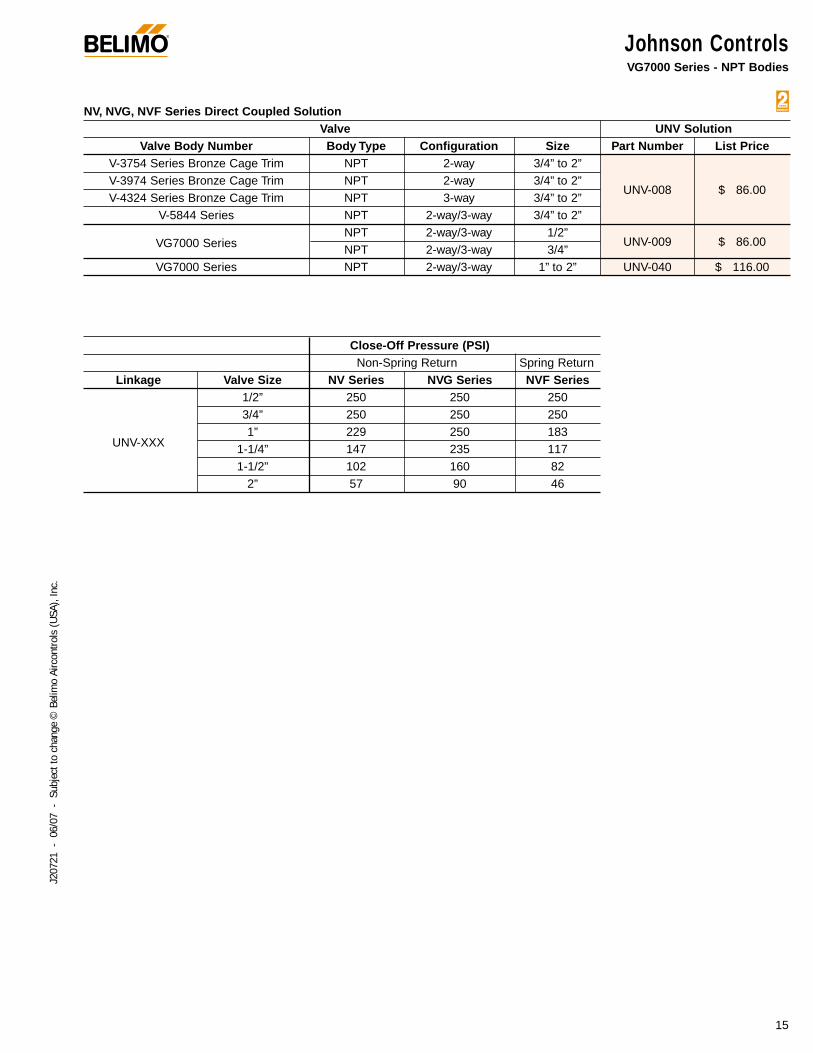
NV, NVG, NVF Series Direct Coupled SolutionValve UNV Solution
Valve Body Number Body Type Configuration Size Part Number List PriceV-3754 Series Bronze Cage Trim NPT 2-way 3/4” to 2”V-3974 Series Bronze Cage Trim NPT 2-way 3/4” to 2”
UNV-008 $ 86.00V-4324 Series Bronze Cage Trim NPT 3-way 3/4” to 2”
V-5844 Series NPT 2-way/3-way 3/4” to 2”
VG7000 SeriesNPT 2-way/3-way 1/2”
UNV-009 $ 86.00NPT 2-way/3-way 3/4”
VG7000 Series NPT 2-way/3-way 1” to 2” UNV-040 $ 116.00
Close-Off Pressure (PSI) Non-Spring Return Spring Return
Linkage Valve Size NV Series NVG Series NVF Series1/2” 250 250 2503/4” 250 250 250
UNV-XXX1” 229 250 183
1-1/4” 147 235 1171-1/2” 102 160 82
2” 57 90 46
Johnson ControlsVG7000 Series - NPT Bodies
®
16
J207
21 -
06/
07 -
Sub
ject
to c
hang
e ©
Bel
imo
Airc
ontro
ls (U
SA),
Inc.
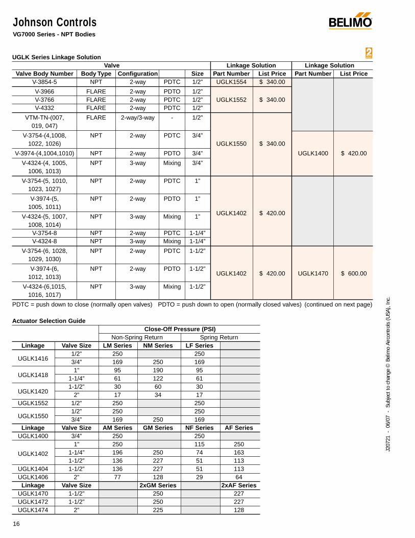
UGLK Series Linkage SolutionValve Linkage Solution Linkage Solution
Valve Body Number Body Type Configuration Size Part Number List Price Part Number List PriceV-3854-5 NPT 2-way PDTC 1/2” UGLK1554 $ 340.00
V-3966 FLARE 2-way PDTO 1/2”V-3766 FLARE 2-way PDTC 1/2” UGLK1552 $ 340.00 V-4332 FLARE 2-way PDTC 1/2”
VTM-TN-(007, FLARE 2-way/3-way - 1/2”019, 047)
V-3754-(4,1008, NPT 2-way PDTC 3/4”1022, 1026) UGLK1550 $ 340.00
V-3974-(4,1004,1010) NPT 2-way PDTO 3/4” UGLK1400 $ 420.00
V-4324-(4, 1005, NPT 3-way Mixing 3/4”1006, 1013)
V-3754-(5, 1010, NPT 2-way PDTC 1”1023, 1027)
V-3974-(5, NPT 2-way PDTO 1”1005, 1011)
V-4324-(5, 1007, NPT 3-way Mixing 1” UGLK1402 $ 420.00
1008, 1014)V-3754-8 NPT 2-way PDTC 1-1/4”V-4324-8 NPT 3-way Mixing 1-1/4”
V-3754-(6, 1028, NPT 2-way PDTC 1-1/2”1029, 1030)
V-3974-(6, NPT 2-way PDTO 1-1/2”UGLK1402 $ 420.00 UGLK1470 $ 600.00 1012, 1013)
V-4324-(6,1015, NPT 3-way Mixing 1-1/2”1016, 1017)
PDTC = push down to close (normally open valves) PDTO = push down to open (normally closed valves) (continued on next page)
Actuator Selection GuideClose-Off Pressure (PSI)
Non-Spring Return Spring ReturnLinkage Valve Size LM Series NM Series LF Series
UGLK14161/2” 250 2503/4” 169 250 169
UGLK14181” 95 190 95
1-1/4” 61 122 61
UGLK14201-1/2” 30 60 30
2” 17 34 17UGLK1552 1/2” 250 250
UGLK15501/2” 250 2503/4” 169 250 169
Linkage Valve Size AM Series GM Series NF Series AF SeriesUGLK1400 3/4” 250 250
UGLK1402
1” 250 115 2501-1/4” 196 250 74 1631-1/2” 136 227 51 113
UGLK1404 1-1/2” 136 227 51 113UGLK1406 2” 77 128 29 64
Linkage Valve Size 2xGM Series 2xAF SeriesUGLK1470 1-1/2” 250 227UGLK1472 1-1/2” 250 227UGLK1474 2” 225 128
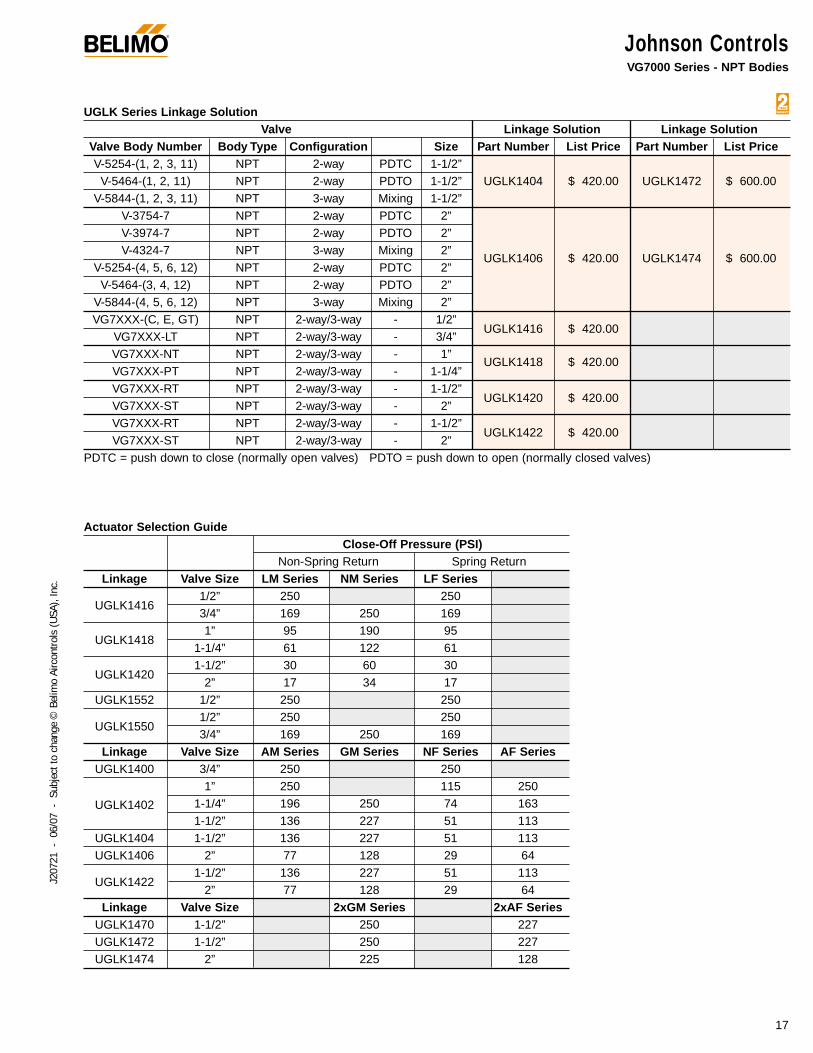
Johnson ControlsVG7000 Series - NPT Bodies
®
17
J207
21 -
06/
07 -
Sub
ject
to c
hang
e ©
Bel
imo
Airc
ontro
ls (U
SA),
Inc.
UGLK Series Linkage SolutionValve Linkage Solution Linkage Solution
Valve Body Number Body Type Configuration Size Part Number List Price Part Number List PriceV-5254-(1, 2, 3, 11) NPT 2-way PDTC 1-1/2”
V-5464-(1, 2, 11) NPT 2-way PDTO 1-1/2” UGLK1404 $ 420.00 UGLK1472 $ 600.00 V-5844-(1, 2, 3, 11) NPT 3-way Mixing 1-1/2”
V-3754-7 NPT 2-way PDTC 2”V-3974-7 NPT 2-way PDTO 2”V-4324-7 NPT 3-way Mixing 2”
UGLK1406 $ 420.00 UGLK1474 $ 600.00 V-5254-(4, 5, 6, 12) NPT 2-way PDTC 2”
V-5464-(3, 4, 12) NPT 2-way PDTO 2”V-5844-(4, 5, 6, 12) NPT 3-way Mixing 2”VG7XXX-(C, E, GT) NPT 2-way/3-way - 1/2”
UGLK1416 $ 420.00 VG7XXX-LT NPT 2-way/3-way - 3/4”VG7XXX-NT NPT 2-way/3-way - 1”
UGLK1418 $ 420.00 VG7XXX-PT NPT 2-way/3-way - 1-1/4”VG7XXX-RT NPT 2-way/3-way - 1-1/2”
UGLK1420 $ 420.00 VG7XXX-ST NPT 2-way/3-way - 2”VG7XXX-RT NPT 2-way/3-way - 1-1/2”
UGLK1422 $ 420.00 VG7XXX-ST NPT 2-way/3-way - 2”
PDTC = push down to close (normally open valves) PDTO = push down to open (normally closed valves)
Actuator Selection GuideClose-Off Pressure (PSI)
Non-Spring Return Spring ReturnLinkage Valve Size LM Series NM Series LF Series
UGLK14161/2” 250 2503/4” 169 250 169
UGLK14181” 95 190 95
1-1/4” 61 122 61
UGLK14201-1/2” 30 60 30
2” 17 34 17UGLK1552 1/2” 250 250
UGLK15501/2” 250 2503/4” 169 250 169
Linkage Valve Size AM Series GM Series NF Series AF SeriesUGLK1400 3/4” 250 250
UGLK1402
1” 250 115 2501-1/4” 196 250 74 1631-1/2” 136 227 51 113
UGLK1404 1-1/2” 136 227 51 113UGLK1406 2” 77 128 29 64
UGLK14221-1/2” 136 227 51 113
2” 77 128 29 64Linkage Valve Size 2xGM Series 2xAF Series
UGLK1470 1-1/2” 250 227UGLK1472 1-1/2” 250 227UGLK1474 2” 225 128
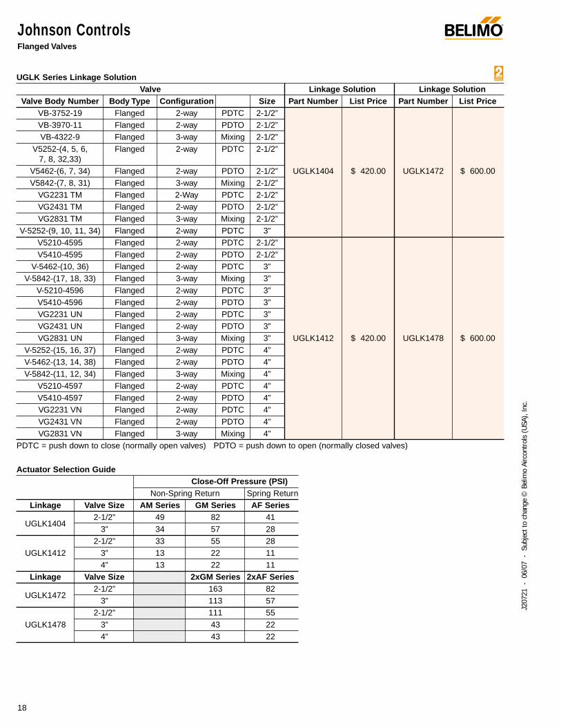
Johnson ControlsFlanged Valves
®
18
J207
21 -
06/
07 -
Sub
ject
to c
hang
e ©
Bel
imo
Airc
ontro
ls (U
SA),
Inc.
UGLK Series Linkage SolutionValve Linkage Solution Linkage Solution
Valve Body Number Body Type Configuration Size Part Number List Price Part Number List PriceVB-3752-19 Flanged 2-way PDTC 2-1/2”VB-3970-11 Flanged 2-way PDTO 2-1/2”VB-4322-9 Flanged 3-way Mixing 2-1/2”
V5252-(4, 5, 6, Flanged 2-way PDTC 2-1/2”7, 8, 32,33)
V5462-(6, 7, 34) Flanged 2-way PDTO 2-1/2” UGLK1404 $ 420.00 UGLK1472 $ 600.00V5842-(7, 8, 31) Flanged 3-way Mixing 2-1/2”
VG2231 TM Flanged 2-Way PDTC 2-1/2”VG2431 TM Flanged 2-way PDTO 2-1/2”VG2831 TM Flanged 3-way Mixing 2-1/2”
V-5252-(9, 10, 11, 34) Flanged 2-way PDTC 3”V5210-4595 Flanged 2-way PDTC 2-1/2”V5410-4595 Flanged 2-way PDTO 2-1/2”
V-5462-(10, 36) Flanged 2-way PDTC 3”V-5842-(17, 18, 33) Flanged 3-way Mixing 3”
V-5210-4596 Flanged 2-way PDTC 3”V5410-4596 Flanged 2-way PDTO 3”VG2231 UN Flanged 2-way PDTC 3”VG2431 UN Flanged 2-way PDTO 3”VG2831 UN Flanged 3-way Mixing 3” UGLK1412 $ 420.00 UGLK1478 $ 600.00
V-5252-(15, 16, 37) Flanged 2-way PDTC 4”V-5462-(13, 14, 38) Flanged 2-way PDTO 4”V-5842-(11, 12, 34) Flanged 3-way Mixing 4”
V5210-4597 Flanged 2-way PDTC 4”V5410-4597 Flanged 2-way PDTO 4”VG2231 VN Flanged 2-way PDTC 4”VG2431 VN Flanged 2-way PDTO 4”VG2831 VN Flanged 3-way Mixing 4”
PDTC = push down to close (normally open valves) PDTO = push down to open (normally closed valves)
Actuator Selection GuideClose-Off Pressure (PSI)
Non-Spring Return Spring ReturnLinkage Valve Size AM Series GM Series AF Series
UGLK14042-1/2” 49 82 41
3” 34 57 282-1/2” 33 55 28
UGLK1412 3” 13 22 114” 13 22 11
Linkage Valve Size 2xGM Series 2xAF Series
UGLK14722-1/2” 163 82
3” 113 572-1/2” 111 55
UGLK1478 3” 43 224” 43 22
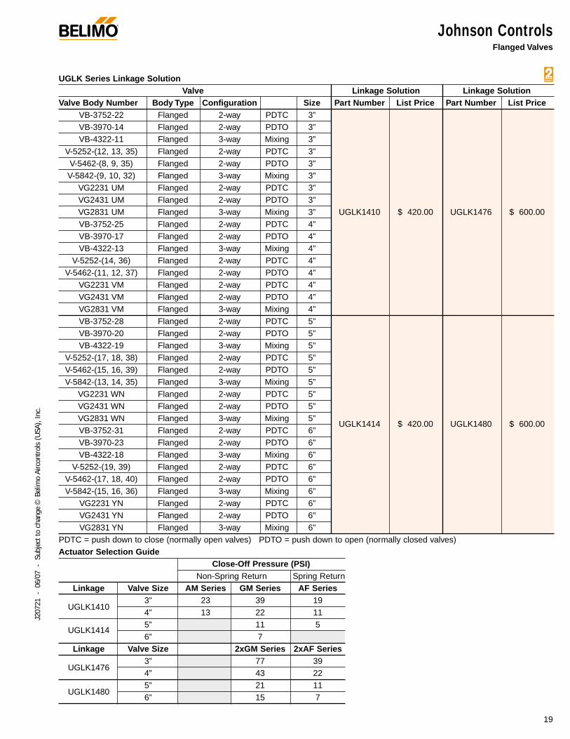
Johnson ControlsFlanged Valves
®
19
J207
21 -
06/
07 -
Sub
ject
to c
hang
e ©
Bel
imo
Airc
ontro
ls (U
SA),
Inc.
UGLK Series Linkage SolutionValve Linkage Solution Linkage Solution
Valve Body Number Body Type Configuration Size Part Number List Price Part Number List PriceVB-3752-22 Flanged 2-way PDTC 3”VB-3970-14 Flanged 2-way PDTO 3”VB-4322-11 Flanged 3-way Mixing 3”
V-5252-(12, 13, 35) Flanged 2-way PDTC 3”V-5462-(8, 9, 35) Flanged 2-way PDTO 3”V-5842-(9, 10, 32) Flanged 3-way Mixing 3”
VG2231 UM Flanged 2-way PDTC 3”VG2431 UM Flanged 2-way PDTO 3”VG2831 UM Flanged 3-way Mixing 3” UGLK1410 $ 420.00 UGLK1476 $ 600.00VB-3752-25 Flanged 2-way PDTC 4”VB-3970-17 Flanged 2-way PDTO 4”VB-4322-13 Flanged 3-way Mixing 4”
V-5252-(14, 36) Flanged 2-way PDTC 4”V-5462-(11, 12, 37) Flanged 2-way PDTO 4”
VG2231 VM Flanged 2-way PDTC 4”VG2431 VM Flanged 2-way PDTO 4”VG2831 VM Flanged 3-way Mixing 4”VB-3752-28 Flanged 2-way PDTC 5”VB-3970-20 Flanged 2-way PDTO 5”VB-4322-19 Flanged 3-way Mixing 5”
V-5252-(17, 18, 38) Flanged 2-way PDTC 5”V-5462-(15, 16, 39) Flanged 2-way PDTO 5”V-5842-(13, 14, 35) Flanged 3-way Mixing 5”
VG2231 WN Flanged 2-way PDTC 5”VG2431 WN Flanged 2-way PDTO 5”VG2831 WN Flanged 3-way Mixing 5”
UGLK1414 $ 420.00 UGLK1480 $ 600.00VB-3752-31 Flanged 2-way PDTC 6”VB-3970-23 Flanged 2-way PDTO 6”VB-4322-18 Flanged 3-way Mixing 6”
V-5252-(19, 39) Flanged 2-way PDTC 6”V-5462-(17, 18, 40) Flanged 2-way PDTO 6”V-5842-(15, 16, 36) Flanged 3-way Mixing 6”
VG2231 YN Flanged 2-way PDTC 6”VG2431 YN Flanged 2-way PDTO 6"VG2831 YN Flanged 3-way Mixing 6”
PDTC = push down to close (normally open valves) PDTO = push down to open (normally closed valves)Actuator Selection Guide
Close-Off Pressure (PSI)Non-Spring Return Spring Return
Linkage Valve Size AM Series GM Series AF Series
UGLK14103” 23 39 194” 13 22 11
UGLK14145” 11 56” 7
Linkage Valve Size 2xGM Series 2xAF Series
UGLK14763” 77 394” 43 22
UGLK14805” 21 116” 15 7
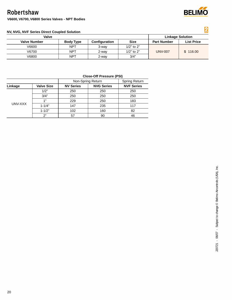
RobertshawV6600, V6700, V6800 Series Valves - NPT Bodies
®
20
J207
21 -
06/
07 -
Sub
ject
to c
hang
e ©
Bel
imo
Airc
ontro
ls (U
SA),
Inc.
NV, NVG, NVF Series Direct Coupled SolutionValve Linkage Solution
Valve Number Body Type Configuration Size Part Number List PriceV6600 NPT 3-way 1/2” to 2”V6700 NPT 2-way 1/2” to 2” UNV-007 $ 116.00V6800 NPT 2-way 3/4”
Close-Off Pressure (PSI)Non-Spring Return Spring Return
Linkage Valve Size NV Series NVG Series NVF Series1/2” 250 250 2503/4” 250 250 250
UNV-XXX1” 229 250 183
1-1/4” 147 235 1171-1/2” 102 160 82
2” 57 90 46

®
21
J207
21 -
06/
07 -
Sub
ject
to c
hang
e ©
Bel
imo
Airc
ontro
ls (U
SA),
Inc.
Siebe\Invensys\Barber ColmanVB7000 and VB9000 Series Valves - NPT BodiesVB804X and VB304X Series Valves - NPT Bodies
NV, NVG, NVF Series Direct Coupled SolutionValve UNV Solution
Valve Number Body Type Configuration Size Part Number List PriceVB7000 series NPT 2-way/3-way 1/2” to 2”VB9000 series NPT 2-way/3-way 1/2” to 1-1/4” UNV-001 $ 54.00
Belimo USA G2 and G3 series NPT 2-way/3-way 1/2” to 2”VB7000 series NPT 2-way/3-way 1/2” to 2”VB9000 series NPT 2-way/3-way 1/2” to 1-1/4” UNV-035 $ 116.00
Belimo USA G2..S NPT 2-way 1/2” to 2”* UNV-035 can be used in steam application up to 50 PSI inlet
Close-Off Pressure (PSI)Non-Spring Return Spring Return
Linkage Valve Size NV Series NVG Series NVF Series1/2” 250 250 2503/4” 250 250 250
UNV-XXX1” 229 250 183
1-1/4” 147 235 1171-1/2” 102 160 82
2” 57 90 46
®
22
J207
21 -
06/
07 -
Sub
ject
to c
hang
e ©
Bel
imo
Airc
ontro
ls (U
SA),
Inc.
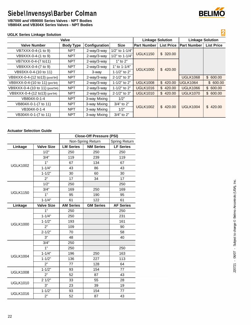
Siebe\Invensys\Barber ColmanVB7000 and VB9000 Series Valves - NPT BodiesVB804X and VB304X Series Valves - NPT Bodies
UGLK Series Linkage SolutionValve Linkage Solution Linkage Solution
Valve Number Body Type Configuration Size Part Number List Price Part Number List PriceVB7XXX-0-4-(1 to 9) NPT 2-way/3-way 1/2” to 1-1/4”
UGLK1150 $ 320.00VB9XXX-0-4-(1 to 9) NPT 2-way/3-way 1/2” to 1-1/4”VB7XXX-0-4-(7 to11) NPT 2-way/3-way 1” to 2”VB9XXX-0-4-(7 to 9) NPT 2-way/3-way 1” to 1-1/4”
UGLK1000 $ 420.00VB93XX-0-4-(10 to 11) NPT 3-way 1-1/2” to 2”
VB9XXX-0-4-(12 to13) (post'94) NPT 2-way/3-way 2-1/2” to 3” UGLK1068 $ 600.00VB9XXX-0-4-(10 to 11) (pre'94) NPT 2-way/3-way 1-1/2” to 2” UGLK1008 $ 420.00 UGLK1064 $ 600.00VB9XXX-0-4-(10 to 11) (post'94) NPT 2-way/3-way 1-1/2” to 2” UGLK1016 $ 420.00 UGLK1066 $ 600.00VB9XXX-0-4-(12 to13) (pre'94) NPT 2-way/3-way 2-1/2” to 3” UGLK1010 $ 420.00 UGLK1070 $ 600.00
VB804X-0-1-4 NPT 3-way Mixing 1/2”VB804X-0-1-(7 to 11) NPT 3-way Mixing 3/4” to 2”
UGLK1002 $ 420.00 UGLK1004 $ 420.00VB304X-0-1-4 NPT 3-way Mixing 1/2”
VB304X-0-1-(7 to 11) NPT 3-way Mixing 3/4” to 2”
Actuator Selection GuideClose-Off Pressure (PSI)
Non-Spring Return Spring ReturnLinkage Valve Size LM Series NM Series LF Series
1/2” 250 250 2503/4” 119 239 119
UGLK10021” 67 134 67
1-1/4” 43 86 431-1/2” 30 60 30
2” 17 34 171/2” 250 250
UGLK11503/4” 169 250 1691” 95 190 95
1-1/4” 61 122 61Linkage Valve Size AM Series GM Series AF Series
1” 250 2501-1/4” 250 231
UGLK10001-1/2” 193 161
2” 109 902-1/2” 70 58
3” 48 403/4” 2501” 250 250
UGLK10041-1/4” 196 250 1631-1/2” 136 227 113
2” 77 128 64
UGLK10081-1/2” 93 154 77
2” 52 87 43
UGLK10102 1/2” 33 55 28
3” 23 39 19
UGLK10161-1/2” 93 154 77
2” 52 87 43
®
23
J207
21 -
06/
07 -
Sub
ject
to c
hang
e ©
Bel
imo
Airc
ontro
ls (U
SA),
Inc.
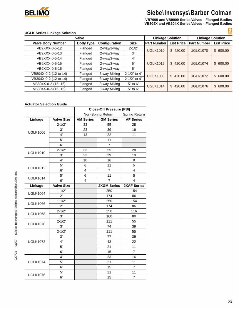
Siebe\Invensys\Barber ColmanVB7000 and VB9000 Series Valves - Flanged BodiesVB804X and VB304X Series Valves - Flanged Bodies
UGLK Series Linkage SolutionValve Linkage Solution Linkage Solution
Valve Body Number Body Type Configuration Size Part Number List Price Part Number List PriceVB9XXX-0-5-12 Flanged 2-way/3-way 2-1/2”
UGLK1010 $ 420.00 UGLK1070 $ 600.00VB9XXX-0-5-13 Flanged 2-way/3-way 3”VB9XXX-0-5-14 Flanged 2-way/3-way 4”VB9XXX-0-5-15 Flanged 2-way/3-way 5” UGLK1012 $ 420.00 UGLK1074 $ 600.00VB9XXX-0-5-16 Flanged 2-way/3-way 6”
VB804X-0-2-(12 to 14) Flanged 3-way Mixing 2-1/2” to 4”UGLK1006 $ 420.00 UGLK1072 $ 600.00
VB304X-0-2-(12 to 14) Flanged 3-way Mixing 2-1/2” to 4”VB804X-0-2-(15, 16) Flanged 3-way Mixing 5” to 6”
UGLK1014 $ 420.00 UGLK1076 $ 600.00 VB304X-0-2-(15, 16) Flanged 3-way Mixing 5” to 6”
Actuator Selection GuideClose-Off Pressure (PSI)
Non-Spring Return Spring ReturnLinkage Valve Size AM Series GM Series AF Series
2-1/2” 33 55 28
UGLK10063” 23 39 194” 13 22 115” 116” 7
UGLK10102-1/2” 33 55 28
3” 23 39 194” 10 16 8
UGLK10125” 6 11 56” 4 7 4
UGLK10145” 6 11 56” 4 7 4
Linkage Valve Size 2XGM Series 2XAF Series
UGLK10641-1/2” 250 154
2” 174 86
UGLK10661-1/2” 250 154
2” 174 86
UGLK10682-1/2” 250 116
3” 160 80
UGLK10702-1/2” 111 55
3” 74 392-1/2” 111 55
3” 77 39UGLK1072 4” 43 22
5” 21 116” 15 74” 33 16
UGLK1074 5” 21 116” 15 7
UGLK10765” 21 116” 15 7
®
24
J207
21 -
06/
07 -
Sub
ject
to c
hang
e ©
Bel
imo
Airc
ontro
ls (U
SA),
Inc.
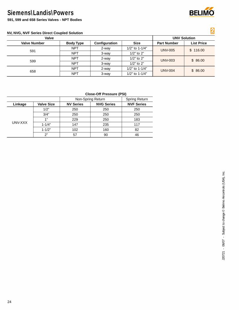
Siemens\Landis\Powers591, 599 and 658 Series Valves - NPT Bodies
NV, NVG, NVF Series Direct Coupled SolutionValve UNV Solution
Valve Number Body Type Configuration Size Part Number List Price
591NPT 2-way 1/2” to 1-1/4” UNV-005 $ 116.00NPT 3-way 1/2” to 2”
599NPT 2-way 1/2” to 2” UNV-003 $ 86.00NPT 3-way 1/2” to 2”
658NPT 2-way 1/2” to 1-1/4” UNV-004 $ 86.00NPT 3-way 1/2” to 1-1/4”
Close-Off Pressure (PSI)Non-Spring Return Spring Return
Linkage Valve Size NV Series NVG Series NVF Series1/2” 250 250 2503/4” 250 250 250
UNV-XXX1” 229 250 183
1-1/4” 147 235 1171-1/2” 102 160 82
2” 57 90 46
®
25
J207
21 -
06/
07 -
Sub
ject
to c
hang
e ©
Bel
imo
Airc
ontro
ls (U
SA),
Inc.
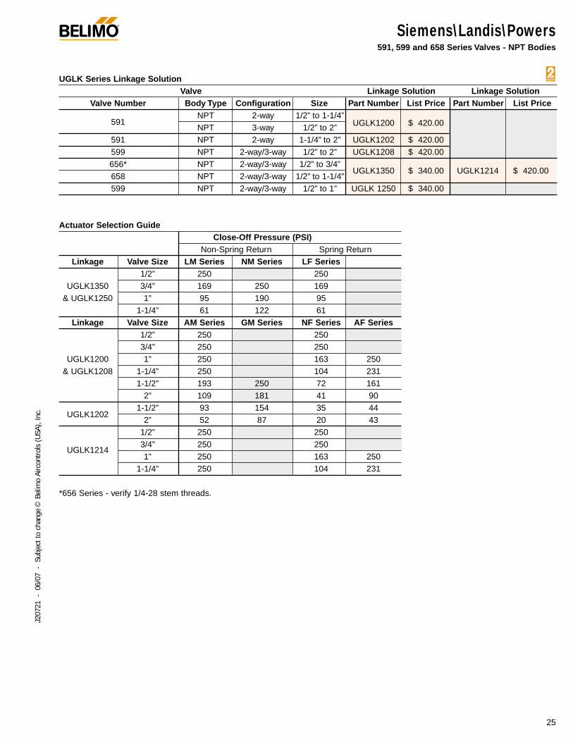
Siemens\Landis\Powers591, 599 and 658 Series Valves - NPT Bodies
UGLK Series Linkage SolutionValve Linkage Solution Linkage Solution
Valve Number Body Type Configuration Size Part Number List Price Part Number List Price
591NPT 2-way 1/2” to 1-1/4”
UGLK1200 $ 420.00NPT 3-way 1/2” to 2”591 NPT 2-way 1-1/4” to 2” UGLK1202 $ 420.00599 NPT 2-way/3-way 1/2” to 2” UGLK1208 $ 420.00656* NPT 2-way/3-way 1/2” to 3/4”
UGLK1350 $ 340.00 UGLK1214 $ 420.00658 NPT 2-way/3-way 1/2” to 1-1/4”599 NPT 2-way/3-way 1/2” to 1” UGLK 1250 $ 340.00
Actuator Selection GuideClose-Off Pressure (PSI)
Non-Spring Return Spring ReturnLinkage Valve Size LM Series NM Series LF Series
1/2” 250 250UGLK1350 3/4” 169 250 169
& UGLK1250 1” 95 190 951-1/4” 61 122 61
Linkage Valve Size AM Series GM Series NF Series AF Series1/2” 250 2503/4” 250 250
UGLK1200 1” 250 163 250& UGLK1208 1-1/4” 250 104 231
1-1/2” 193 250 72 1612” 109 181 41 90
UGLK12021-1/2” 93 154 35 44
2” 52 87 20 431/2” 250 250
UGLK12143/4” 250 2501” 250 163 250
1-1/4” 250 104 231
*656 Series - verify 1/4-28 stem threads.
®
26
J207
21 -
06/
07 -
Sub
ject
to c
hang
e ©
Bel
imo
Airc
ontro
ls (U
SA),
Inc.
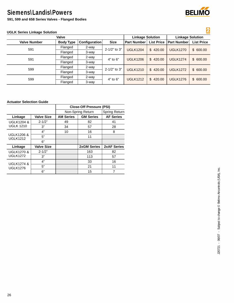
Siemens\Landis\Powers591, 599 and 658 Series Valves - Flanged Bodies
UGLK Series Linkage SolutionValve Linkage Solution Linkage Solution
Valve Number Body Type Configuration Size Part Number List Price Part Number List Price
591Flanged 2-way
2-1/2” to 3” UGLK1204 $ 420.00 UGLK1270 $ 600.00Flanged 3-way
591Flanged 2-way
4” to 6” UGLK1206 $ 420.00 UGLK1274 $ 600.00Flanged 3-way
599Flanged 2-way
2-1/2” to 3” UGLK1210 $ 420.00 UGLK1272 $ 600.00Flanged 3-way
599Flanged 2-way
4” to 6” UGLK1212 $ 420.00 UGLK1276 $ 600.00Flanged 3-way
Actuator Selection GuideClose-Off Pressure (PSI)
Non-Spring Return Spring ReturnLinkage Valve Size AM Series GM Series AF Series
UGLK1204 & 2-1/2” 49 82 41UGLK 1210 3” 34 57 28
UGLK1206 &4” 10 16 85” 11UGLK12126”
Linkage Valve Size 2xGM Series 2xAF Series
UGLK1270 & 2-1/2” 163 82UGLK1272 3” 113 57
UGLK1274 &4” 33 16
UGLK1276 5” 21 116” 15 7
Warren ControlsNPT Bodies
®
27
J207
21 -
06/
07 -
Sub
ject
to c
hang
e ©
Bel
imo
Airc
ontro
ls (U
SA),
Inc.
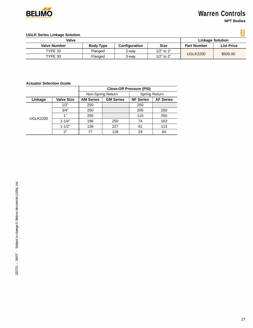
UGLK Series Linkage SolutionValve Linkage Solution
Valve Number Body Type Configuration Size Part Number List PriceTYPE 20 Flanged 2-way 1/2” to 2”
UGLK2200 $500.00 TYPE 30 Flanged 3-way 1/2” to 2”
Actuator Selection GuideClose-Off Pressure (PSI)
Non-Spring Return Spring ReturnLinkage Valve Size AM Series GM Series NF Series AF Series
1/2” 250 2503/4” 250 205 250
UGLK22001” 250 115 250
1-1/4” 196 250 74 1631-1/2” 136 227 51 113
2” 77 128 29 64

Warren ControlsFlanged Bodies
®
28
J207
21 -
06/
07 -
Sub
ject
to c
hang
e ©
Bel
imo
Airc
ontro
ls (U
SA),
Inc.
UGLK Series Linkage SolutionValve Linkage Solution Linkage Solution
Valve Number Body Type Configuration Size Part Number List Price Part Number List PriceTYPE 20 Flanged 2-way 2-1/2" to 3"TYPE 22 Flanged 2-way 2-1/2" to 4"
UGLK2200 $ 500.00 UGLK2270 $ 600.00TYPE 30 Flanged 3-way 2-1/2" to 3"TYPE 32 Flanged 3-way 2-1/2" to 3"1800 BAL Flanged 2-way 2-1/2" to 6"
100 SGL SEAT Flanged 2-way 2-1/2" to 6"1800 3W MIX Flanged 3-way 2-1/2" to 6"1800 3W DIV Flanged 3-way 2-1/2" to 6"
UGLK2202 $ 420.00 UGLK2272 $ 600.00TYPE 20 Flanged 2-way 4" to 6"TYPE 22 Flanged 2-way 5" to 6"TYPE 30 Flanged 3-way 4" to 6"TYPE 32 Flanged 3-way 4" to 6"
Actuator Selection Guide
Close-Off Pressure (PSI)Non-Spring Return Spring Return
Linkage Valve Size AM Series GM Series NF Series AF Series2-1/2" 49 82 18 41
UGLK2200 3" 34 57 13 284" 19 32 7 16
2-1/2" 25 42 9 213" 18 29 7 15
UGLK2202 4" 10 16 85" 11 56" 7 4
Linkage Valve Size 2XGM Series 2XAF Series2-1/2" 163 82
UGLK2270 3" 113 574" 64 32
2-1/2" 84 423" 58 29
UGLK2272 4" 33 165" 21 116" 15 7
NVG Series Direct Coupled SolutionValve UNV Solution
Valve Body Number Body Type Configuration Size Part Number List PriceType 20 Flanged 2-way 2-1/2” to 3”Type 22 Flanged 2-way 2-1/2” to 3”
UNV-051 $ 116.00Type 30 Flanged 3-way 2-1/2” to 3”Type 32 Flanged 3-way 2-1/2” to 3”
Close-Off Pressure (PSI)2-way 3-way
Linkage Valve Size NVG Series
UNV-0512-1/2” 69 100
3” 48 100
®
29
J207
21 -
06/
07 -
Sub
ject
to c
hang
e ©
Bel
imo
Airc
ontro
ls (U
SA),
Inc.
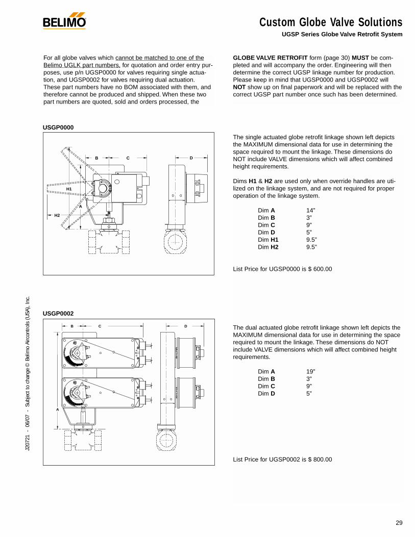
Custom Globe Valve SolutionsUGSP Series Globe Valve Retrofit System
For all globe valves which cannot be matched to one of theBelimo UGLK part numbers, for quotation and order entry pur-poses, use p/n UGSP0000 for valves requiring single actua-tion, and UGSP0002 for valves requiring dual actuation.These part numbers have no BOM associated with them, andtherefore cannot be produced and shipped. When these twopart numbers are quoted, sold and orders processed, the
GLOBE VALVE RETROFIT form (page 30) MUST be com-pleted and will accompany the order. Engineering will thendetermine the correct UGSP linkage number for production.Please keep in mind that UGSP0000 and UGSP0002 willNOT show up on final paperwork and will be replaced with thecorrect UGSP part number once such has been determined.
A
B C
H1
H2
D
A
RL
L
B
R
C D
The single actuated globe retrofit linkage shown left depictsthe MAXIMUM dimensional data for use in determining thespace required to mount the linkage. These dimensions doNOT include VALVE dimensions which will affect combinedheight requirements.
Dims H1 & H2 are used only when override handles are uti-lized on the linkage system, and are not required for properoperation of the linkage system.
Dim A 14”Dim B 3”Dim C 9”Dim D 5”Dim H1 9.5”Dim H2 9.5”
List Price for UGSP0000 is $ 600.00
The dual actuated globe retrofit linkage shown left depicts theMAXIMUM dimensional data for use in determining the spacerequired to mount the linkage. These dimensions do NOTinclude VALVE dimensions which will affect combined heightrequirements.
Dim A 19”Dim B 3”Dim C 9”Dim D 5”
List Price for UGSP0002 is $ 800.00
USGP0000
USGP0002
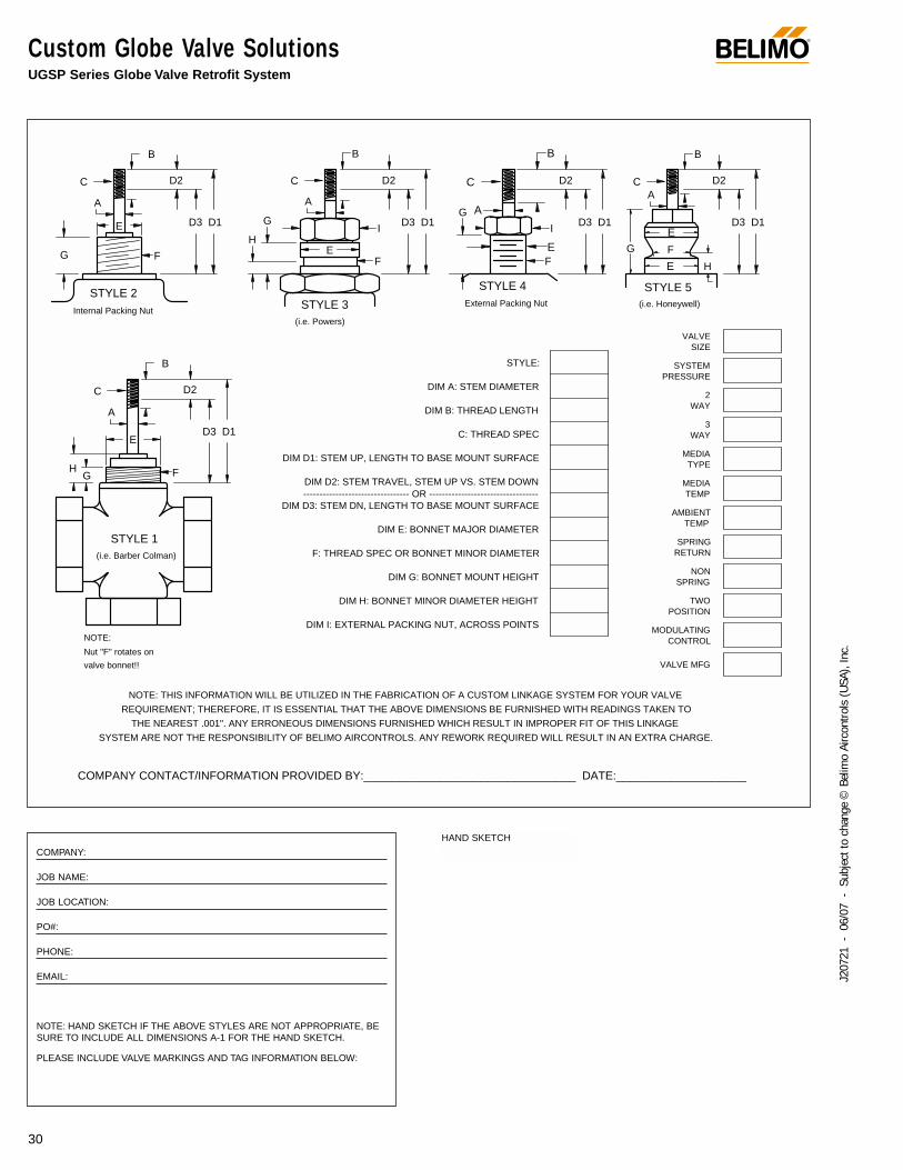
Custom Globe Valve SolutionsUGSP Series Globe Valve Retrofit System
®
30
J207
21 -
06/
07 -
Sub
ject
to c
hang
e ©
Bel
imo
Airc
ontro
ls (U
SA),
Inc.
COMPANY CONTACT/INFORMATION PROVIDED BY:_______________________________ DATE:___________________
NOTE: THIS INFORMATION WILL BE UTILIZED IN THE FABRICATION OF A CUSTOM LINKAGE SYSTEM FOR YOUR VALVE
REQUIREMENT; THEREFORE, IT IS ESSENTIAL THAT THE ABOVE DIMENSIONS BE FURNISHED WITH READINGS TAKEN TO
THE NEAREST .001". ANY ERRONEOUS DIMENSIONS FURNISHED WHICH RESULT IN IMPROPER FIT OF THIS LINKAGE
SYSTEM ARE NOT THE RESPONSIBILITY OF BELIMO AIRCONTROLS. ANY REWORK REQUIRED WILL RESULT IN AN EXTRA CHARGE.
Internal Packing NutExternal Packing Nut
VALVESIZE
SYSTEMPRESSURE
2WAY
3WAY
MEDIATYPE
MEDIATEMP
AMBIENTTEMP
POSITION
MODULATINGCONTROL
RETURN
SPRING
TWO
VALVE MFG
NON
SPRING
D3 D1 C: THREAD SPEC
DIM E: BONNET MAJOR DIAMETER
DIM H: BONNET MINOR DIAMETER HEIGHT
DIM G: BONNET MOUNT HEIGHT
DIM I: EXTERNAL PACKING NUT, ACROSS POINTS
F: THREAD SPEC OR BONNET MINOR DIAMETER
DIM D2: STEM TRAVEL, STEM UP VS. STEM DOWN
DIM D1: STEM UP, LENGTH TO BASE MOUNT SURFACE
DIM D3: STEM DN, LENGTH TO BASE MOUNT SURFACE--------------------------------- OR ----------------------------------
Nut "F" rotates on
(i.e. Barber Colman)
STYLE 1
HG
E
F
valve bonnet!!
NOTE:
D3
DIM B: THREAD LENGTH
DIM A: STEM DIAMETER
STYLE:
STYLE 3(i.e. Powers)
D2
A
STYLE 2
C
B
G
A
C
E
F
D2
D1D3
H
G
A
C
B
I
EF
D3
D2
D1
STYLE 4
AG
C
I
EF
D2
B B
D2
STYLE 5(i.e. Honeywell)
A
G
D1
C
E
F
E
H
D1D3
B
COMPANY:
JOB NAME:
JOB LOCATION:
PO#:
PHONE:
EMAIL:
NOTE: HAND SKETCH IF THE ABOVE STYLES ARE NOT APPROPRIATE, BESURE TO INCLUDE ALL DIMENSIONS A-1 FOR THE HAND SKETCH.
PLEASE INCLUDE VALVE MARKINGS AND TAG INFORMATION BELOW:
HAND SKETCH
Custom Globe Valve SolutionsUGSP Series Globe Valve Retrofit System
®
31
J207
21 -
06/
07 -
Sub
ject
to c
hang
e ©
Bel
imo
Airc
ontro
ls (U
SA),
Inc.
Instructions for properly completing this form:
Dimensions A, B & C relate to the existing valve stem. DimA is the stem diameter where it is NOT threaded. Dim Brefers to the length of the threaded region on the valvestem, and Dim C is the actual thread specification, (1/4-28,5/16-24, 3/8-24, 7/16-20 & 1/2-20 are typical). This informa-tion is used to design a stem adapter which will connect thevalve stem to the new linkage drive rack. It is important tospecify the correct thread pattern, as incorrect data will pre-vent the stem adapter from attaching to your valve. If youcannot determine the correct thread spec, you can send anut from the valve stem to the Danbury office and we willmatch the correct specification. In some cases where oldervalves are concerned, some valve stems must be trimmedin the field to allow attachment of the linkage system. Inthese cases, a stem adapter is designed which will "bite"into the smooth surface of the valve stem itself.
Dimensions D1, D2 & D3 are used to determine the heightof the linkage assembly required to clear the valves’ fullstroke. Two of these three dimensions are required to man-ufacture the correct linkage system for your valve. Thesedimensions also provide the information necessary to deter-mine valve stroke. The maximum stroke from Belimo globevalve retrofit systems is 1-1/2”.
Dimension E refers to the valve bonnet diameter, regardlessif threads are present or not. Over time, impurities will reactto the bonnet threads and corrode them to the point wherethey no longer meet the original thread specification.Because of this, we manufacture slip fit collars designed toslide over the bonnet threads, and locking setscrews areprovided which "bite" into the original threads. All retrofitsystems are designed to work with the raw valve body anddo not account for previous actuation components whichmust be removed from the valve body before attaching thenew linkage system.
Dimension F refers to the thread specification on threadedbonnets, and refers to the minor diameter on slip on bon-nets (Landis type). This information helps us determine thelength of the locking devices required to hold the collar ontothe bonnet.
Dimensions G & H are used to determine working height ofthe bonnet region of your globe valve, while Dim I is used incalculating the minimum ID of the collar that will fit over thepacking nut.
Additionally, there are several boxes requesting informationabout the environment and process in which this linkagesystem will be utilized.
ALL the information contained on this form is required to guaran-tee the complete, perfect fit of your retrofit system. Keep in mindthat retrofit kits are designed with close-tolerance componentswhich afford the most efficient linkage system for the facility.Obviously, measurements rounded to the nearest 1/8 or 1/16inch will not perform as well (sometimes not at all) as a kitdesigned around careful measurements using proper equipment.Our designs are typically +.005" tolerance. This translates intoroughly 20 to 50 possible designs under the "just a little larger"request to repair a faulty linkage due to mis-information.
Disclaimer:
While we will do our best to provide a linkage system designedaround your specifications and measurements, we cannot beheld responsible for linkages which do not fit as a result of faultyinformation given to Belimo. We will be happy to re-work compo-nents which do not fit properly for a nominal fee.
To reduce the possibility of incorrect linkage solutions, werespectfully request that you fill out the retrofit form completelyand forward that information with your order. This will serve as adouble check between your valve and the actuator/linkage pack-age designed for your application.
Actuation, weather shields and linkages cannot be pre-assem-bled at the Belimo factory prior to your receipt. The linkages aredesigned to be attached onto the valve body first, then optionalweather shields, and finally actuation products.
Close-off pressures are calculated using actuator torque, valvestroke, and valve area. Other factors may affect the rated close-off pressures, including flow rates, system maintenance sched-ules, chemicals used in the shot feeder process, vicinity topumps, condition of valve stem seals, and assembly of linkagematerial in the field.
Valves that are being considered for retrofit of actuation should beanalyzed for their life expectancy before the retrofit has takenplace. Valves that leak through stem seals or casings will continueto leak with the new linkage system in place, maybe even moreso. Rebuilding the packing on these valves may be more costlythan replacing the valves themselves. In some instances, oldervalve stem heights will require field modifications to the valve inorder to utilize the retrofit kit. Belimo takes no responsibility for theoperation of these valves after they have been modified.
®
32
J207
21 -
06/
07 -
Sub
ject
to c
hang
e ©
Bel
imo
Airc
ontro
ls (U
SA),
Inc.
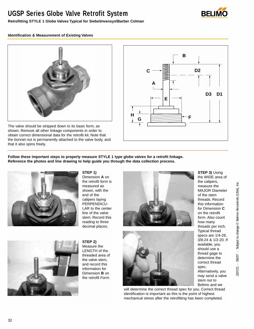
UGSP Series Globe Valve Retrofit SystemRetrofitting STYLE 1 Globe Valves Typical for Siebe\Invensys\Barber Colman
STEP 1)Dimension A onthe retrofit form ismeasured asshown, with theend of thecalipers layingPERPENDICU-LAR to the centerline of the valvestem. Record thisreading to threedecimal places.
STEP 2)Measure theLENGTH of thethreaded area ofthe valve stem,and record thisinformation forDimension B onthe retrofit Form.
STEP 3) Usingthe WIDE area ofthe calipers,measure theMAJOR Diameterof the stemthreads. Recordthis informationfor Dimension Con the retrofitform. Also counthow manythreads per inch.Typical threadspecs are 1/4-28,3/8-24 & 1/2-20. Ifavailable, youshould use athread gage todetermine thecorrect threadspec.Alternatively, youmay send a valvestem nut toBelimo and we
will determine the correct thread spec for you. Correct threadidentification is important as this is the point of highestmechanical stress after the retrofitting has been completed.
Identification & Measurement of Existing Valves
E
GH
A
C
F
D1D3
D2
B
Follow these important steps to properly measure STYLE 1 type globe valves for a retrofit linkage.Reference the photos and line drawing to help guide you through the data collection process.
The valve should be stripped down to its basic form, asshown. Remove all other linkage components in order toobtain correct dimensional data for the retrofit kit. Note thatthe bonnet nut is permanently attached to the valve body, andthat it also spins freely.
®
33
J207
21 -
06/
07 -
Sub
ject
to c
hang
e ©
Bel
imo
Airc
ontro
ls (U
SA),
Inc.
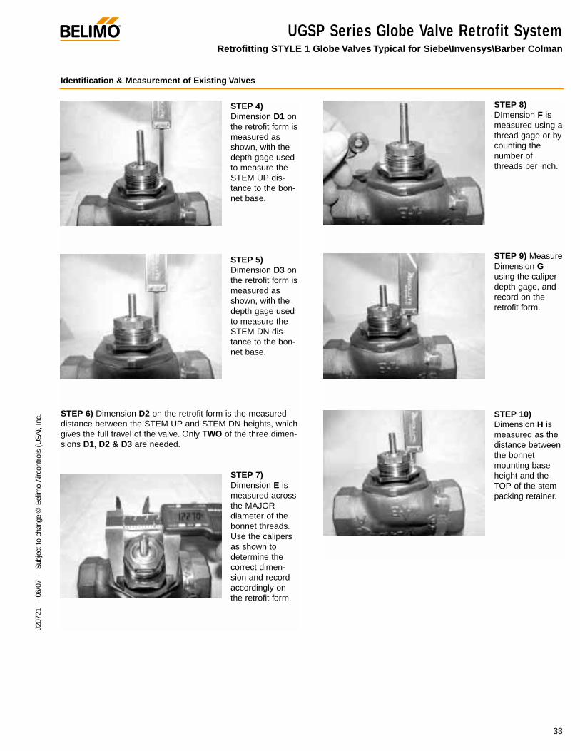
UGSP Series Globe Valve Retrofit SystemRetrofitting STYLE 1 Globe Valves Typical for Siebe\Invensys\Barber Colman
Identification & Measurement of Existing Valves
STEP 4)Dimension D1 onthe retrofit form ismeasured asshown, with thedepth gage usedto measure theSTEM UP dis-tance to the bon-net base.
STEP 5)Dimension D3 onthe retrofit form ismeasured asshown, with thedepth gage usedto measure theSTEM DN dis-tance to the bon-net base.
STEP 6) Dimension D2 on the retrofit form is the measureddistance between the STEM UP and STEM DN heights, whichgives the full travel of the valve. Only TWO of the three dimen-sions D1, D2 & D3 are needed.
STEP 7)Dimension E ismeasured acrossthe MAJORdiameter of thebonnet threads.Use the calipersas shown todetermine thecorrect dimen-sion and recordaccordingly onthe retrofit form.
STEP 8)DImension F ismeasured using athread gage or bycounting thenumber ofthreads per inch.
STEP 9) MeasureDimension Gusing the caliperdepth gage, andrecord on theretrofit form.
STEP 10)Dimension H ismeasured as thedistance betweenthe bonnetmounting baseheight and theTOP of the stempacking retainer.

®
34
J207
21 -
06/
07 -
Sub
ject
to c
hang
e ©
Bel
imo
Airc
ontro
ls (U
SA),
Inc.
UGSP Series Globe Valve Retrofit SystemRetrofitting STYLE 2 Globe Valves Typical for Internal Packing Nut Type Valves
Identification & Measurement of Existing Valves
STEP 1)Dimension A onthe retrofit form ismeasured asshown, with theend of thecalipers layingPERPENDICU-LAR to the centerline of the valvestem. Record thisreading to threedecimal places.
STEP 2)Measure theLENGTH of thethreaded area ofthe valve stem,and record thisinformation forDimension B onthe retrofit Form.
STEP 3) Usingthe WIDE area ofthe calipers,measure theMAJOR Diameterof the stemthreads. Recordthis informationfor Dimension Con the retrofitform. Also counthow manythreads per inch.Typical threadspecs are 1/4-28,3/8-24 & 1/2-20. Ifavailable, youshould use athread gage todetermine thecorrect threadspec.Alternatively, youmay send a valvestem nut toBelimo and we
will determine the correct thread spec for you. Correct threadidentification is important as this is the point of highestmechanical stress after the retrofitting has been completed.
G
E
A
C
D3
F
D2
D1
B
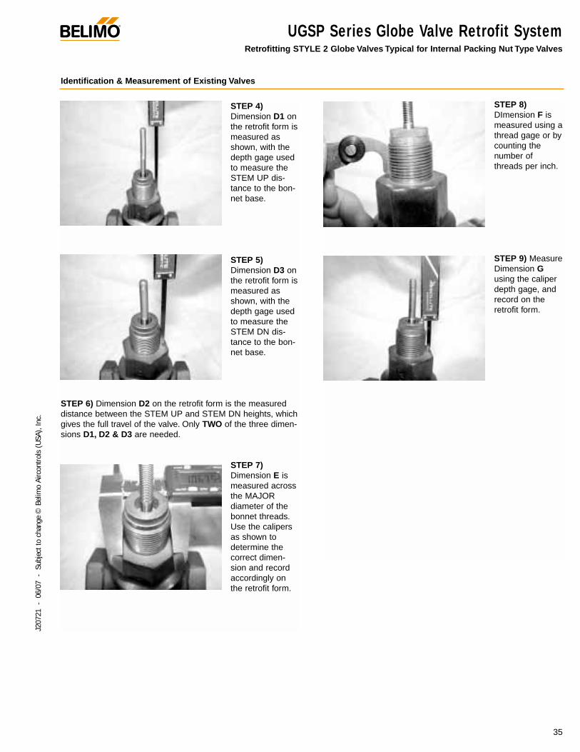
Follow these important steps to properly measure STYLE 2 type globe valves for a retrofit linkage.Reference the photos and line drawing to help guide you through the data collection process.
The valve should be stripped down to its basic form, asshown. Remove all other linkage components in order toobtain correct dimensional data for the retrofit kit. Note thatthe packing nut is inside the bonnet, and does NOT interferewith the bonnet threads.
®
35
J207
21 -
06/
07 -
Sub
ject
to c
hang
e ©
Bel
imo
Airc
ontro
ls (U
SA),
Inc.
UGSP Series Globe Valve Retrofit SystemRetrofitting STYLE 2 Globe Valves Typical for Internal Packing Nut Type Valves
Identification & Measurement of Existing Valves
STEP 4)Dimension D1 onthe retrofit form ismeasured asshown, with thedepth gage usedto measure theSTEM UP dis-tance to the bon-net base.
STEP 5)Dimension D3 onthe retrofit form ismeasured asshown, with thedepth gage usedto measure theSTEM DN dis-tance to the bon-net base.
STEP 6) Dimension D2 on the retrofit form is the measureddistance between the STEM UP and STEM DN heights, whichgives the full travel of the valve. Only TWO of the three dimen-sions D1, D2 & D3 are needed.
STEP 7)Dimension E ismeasured acrossthe MAJORdiameter of thebonnet threads.Use the calipersas shown todetermine thecorrect dimen-sion and recordaccordingly onthe retrofit form.
STEP 8)DImension F ismeasured using athread gage or bycounting thenumber ofthreads per inch.
STEP 9) MeasureDimension Gusing the caliperdepth gage, andrecord on theretrofit form.
®
36
J207
21 -
06/
07 -
Sub
ject
to c
hang
e ©
Bel
imo
Airc
ontro
ls (U
SA),
Inc.
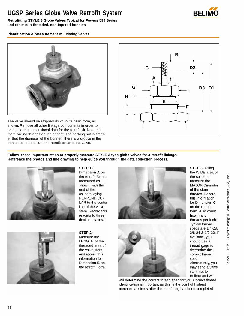
UGSP Series Globe Valve Retrofit SystemRetrofitting STYLE 3 Globe Valves Typical for Powers 599 Series and other non-threaded, non-tapered bonnets
Identification & Measurement of Existing Valves
STEP 1)Dimension A onthe retrofit form ismeasured asshown, with theend of thecalipers layingPERPENDICU-LAR to the centerline of the valvestem. Record thisreading to threedecimal places.
STEP 2)Measure theLENGTH of thethreaded area ofthe valve stem,and record thisinformation forDimension B onthe retrofit Form.
STEP 3) Usingthe WIDE area ofthe calipers,measure theMAJOR Diameterof the stemthreads. Recordthis informationfor Dimension Con the retrofitform. Also counthow manythreads per inch.Typical threadspecs are 1/4-28,3/8-24 & 1/2-20. Ifavailable, youshould use athread gage todetermine thecorrect threadspec.Alternatively, youmay send a valvestem nut toBelimo and we
will determine the correct thread spec for you. Correct threadidentification is important as this is the point of highestmechanical stress after the retrofitting has been completed.
F
H
G
A
C
E
B
D3I
D1
D2
Follow these important steps to properly measure STYLE 3 type globe valves for a retrofit linkage.Reference the photos and line drawing to help guide you through the data collection process.
The valve should be stripped down to its basic form, asshown. Remove all other linkage components in order toobtain correct dimensional data for the retrofit kit. Note thatthere are no threads on the bonnet. The packing nut is small-er that the diameter of the bonnet. There is a groove in thebonnet used to secure the retrofit collar to the valve.
®
37
J207
21 -
06/
07 -
Sub
ject
to c
hang
e ©
Bel
imo
Airc
ontro
ls (U
SA),
Inc.
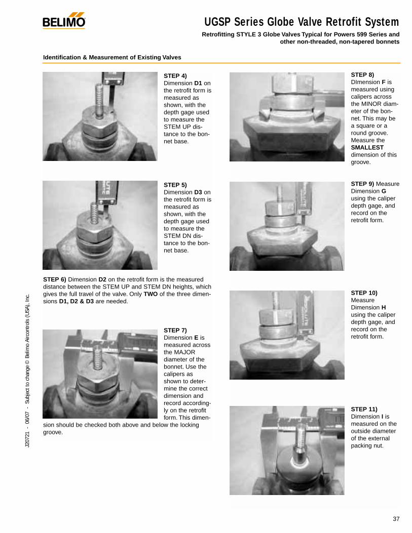
UGSP Series Globe Valve Retrofit SystemRetrofitting STYLE 3 Globe Valves Typical for Powers 599 Series and
other non-threaded, non-tapered bonnets
Identification & Measurement of Existing Valves
STEP 4)Dimension D1 onthe retrofit form ismeasured asshown, with thedepth gage usedto measure theSTEM UP dis-tance to the bon-net base.
STEP 5)Dimension D3 onthe retrofit form ismeasured asshown, with thedepth gage usedto measure theSTEM DN dis-tance to the bon-net base.
STEP 6) Dimension D2 on the retrofit form is the measureddistance between the STEM UP and STEM DN heights, whichgives the full travel of the valve. Only TWO of the three dimen-sions D1, D2 & D3 are needed.
STEP 7)Dimension E ismeasured acrossthe MAJORdiameter of thebonnet. Use thecalipers asshown to deter-mine the correctdimension andrecord according-ly on the retrofitform. This dimen-
sion should be checked both above and below the lockinggroove.
STEP 8)DImension F ismeasured usingcalipers acrossthe MINOR diam-eter of the bon-net. This may bea square or around groove.Measure theSMALLESTdimension of thisgroove.
STEP 9) MeasureDimension Gusing the caliperdepth gage, andrecord on theretrofit form.
STEP 10)MeasureDimension Husing the caliperdepth gage, andrecord on theretrofit form.
STEP 11)Dimension I ismeasured on theoutside diameterof the externalpacking nut.

®
38
J207
21 -
06/
07 -
Sub
ject
to c
hang
e ©
Bel
imo
Airc
ontro
ls (U
SA),
Inc.
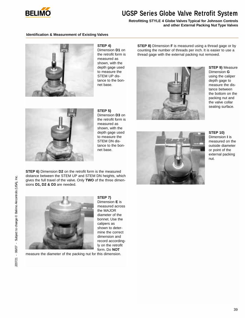
UGSP Series Globe Valve Retrofit SystemRetrofitting STYLE 4 Globe Valves Typical for Johnson Controls and other External Packing Nut Type Valves
Identification & Measurement of Existing Valves
STEP 1)Dimension A onthe retrofit form ismeasured asshown, with theend of thecalipers layingPERPENDICU-LAR to the centerline of the valvestem. Record thisreading to threedecimal places.
STEP 2)Measure theLENGTH of thethreaded area ofthe valve stem,and record thisinformation forDimension B onthe retrofit Form.
STEP 3) Usingthe WIDE area ofthe calipers,measure theMAJOR Diameterof the stemthreads. Recordthis informationfor Dimension Con the retrofitform. Also counthow manythreads per inch.Typical threadspecs are 1/4-28,3/8-24 & 1/2-20. Ifavailable, youshould use athread gage todetermine thecorrect threadspec.Alternatively, youmay send a valvestem nut toBelimo and we
will determine the correct thread spec for you. Correct threadidentification is important as this is the point of highestmechanical stress after the retrofitting has been completed.
C
G
A
D2
E
F
ID3 D1
B
Follow these important steps to properly measure STYLE 4 type globe valves for a retrofit linkage.Reference the photos and line drawing to help guide you through the data collection process.
The valve should be stripped down to its basic form, asshown. Remove all other linkage components in order toobtain correct dimensional data for the retrofit kit. Note thatmany pneumatically operated valves have hardware that mustbe removed from the threaded bonnet area before measure-ments can be taken.
®
39
J207
21 -
06/
07 -
Sub
ject
to c
hang
e ©
Bel
imo
Airc
ontro
ls (U
SA),
Inc.
UGSP Series Globe Valve Retrofit SystemRetrofitting STYLE 4 Globe Valves Typical for Johnson Controls
and other External Packing Nut Type Valves
Identification & Measurement of Existing Valves
STEP 4)Dimension D1 onthe retrofit form ismeasured asshown, with thedepth gage usedto measure theSTEM UP dis-tance to the bon-net base.
STEP 5)Dimension D3 onthe retrofit form ismeasured asshown, with thedepth gage usedto measure theSTEM DN dis-tance to the bon-net base.
STEP 6) Dimension D2 on the retrofit form is the measureddistance between the STEM UP and STEM DN heights, whichgives the full travel of the valve. Only TWO of the three dimen-sions D1, D2 & D3 are needed.
STEP 7)Dimension E ismeasured acrossthe MAJORdiameter of thebonnet. Use thecalipers asshown to deter-mine the correctdimension andrecord according-ly on the retrofitform. Do NOT
measure the diameter of the packing nut for this dimension.
STEP 8) DImension F is measured using a thread gage or bycounting the number of threads per inch. It is easier to use athread gage with the external packing nut removed.
STEP 9) MeasureDimension Gusing the caliperdepth gage tomeasure the dis-tance betweenthe bottom on thepacking nut andthe valve collarseating surface.
STEP 10)Dimension I ismeasured on theoutside diameteror point of theexternal packingnut.
®
40
J207
21 -
06/
07 -
Sub
ject
to c
hang
e ©
Bel
imo
Airc
ontro
ls (U
SA),
Inc.
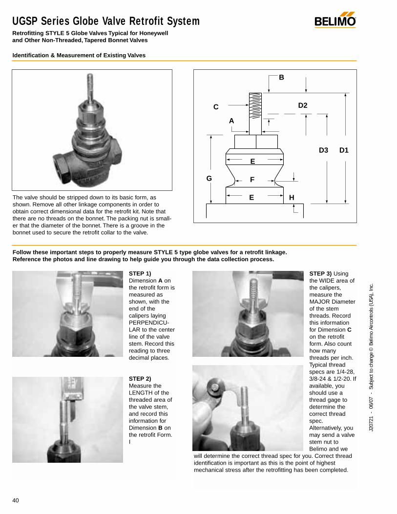
UGSP Series Globe Valve Retrofit SystemRetrofitting STYLE 5 Globe Valves Typical for Honeywell and Other Non-Threaded, Tapered Bonnet Valves
Identification & Measurement of Existing Valves
STEP 1)Dimension A onthe retrofit form ismeasured asshown, with theend of thecalipers layingPERPENDICU-LAR to the centerline of the valvestem. Record thisreading to threedecimal places.
STEP 2)Measure theLENGTH of thethreaded area ofthe valve stem,and record thisinformation forDimension B onthe retrofit Form.I
STEP 3) Usingthe WIDE area ofthe calipers,measure theMAJOR Diameterof the stemthreads. Recordthis informationfor Dimension Con the retrofitform. Also counthow manythreads per inch.Typical threadspecs are 1/4-28,3/8-24 & 1/2-20. Ifavailable, youshould use athread gage todetermine thecorrect threadspec.Alternatively, youmay send a valvestem nut toBelimo and we
will determine the correct thread spec for you. Correct threadidentification is important as this is the point of highestmechanical stress after the retrofitting has been completed.
G F
E
E
A
C
H
D3
D2
B
D1
Follow these important steps to properly measure STYLE 5 type globe valves for a retrofit linkage.Reference the photos and line drawing to help guide you through the data collection process.
The valve should be stripped down to its basic form, asshown. Remove all other linkage components in order toobtain correct dimensional data for the retrofit kit. Note thatthere are no threads on the bonnet. The packing nut is small-er that the diameter of the bonnet. There is a groove in thebonnet used to secure the retrofit collar to the valve.
UGSP Series Globe Valve Retrofit SystemRetrofitting STYLE 5 Globe Valves Typical for Honeywell
and Other Non-Threaded, Tapered Bonnet Valves
®
41
J207
21 -
06/
07 -
Sub
ject
to c
hang
e ©
Bel
imo
Airc
ontro
ls (U
SA),
Inc.
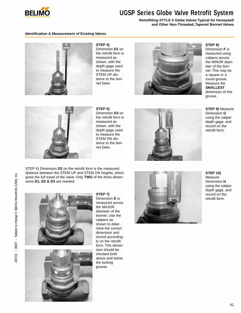
Identification & Measurement of Existing Valves
STEP 4)Dimension D1 onthe retrofit form ismeasured asshown, with thedepth gage usedto measure theSTEM UP dis-tance to the bon-net base.
STEP 5)Dimension D3 onthe retrofit form ismeasured asshown, with thedepth gage usedto measure theSTEM DN dis-tance to the bon-net base.
STEP 6) Dimension D2 on the retrofit form is the measureddistance between the STEM UP and STEM DN heights, whichgives the full travel of the valve. Only TWO of the three dimen-sions D1, D2 & D3 are needed.
STEP 7)Dimension E ismeasured acrossthe MAJORdiameter of thebonnet. Use thecalipers asshown to deter-mine the correctdimension andrecord according-ly on the retrofitform. This dimen-sion should bechecked bothabove and belowthe lockinggroove.
STEP 8)DImension F ismeasured usingcalipers acrossthe MINOR diam-eter of the bon-net. This may bea square or around groove.Measure theSMALLESTdimension of thisgroove.
STEP 9) MeasureDimension Gusing the caliperdepth gage, andrecord on theretrofit form.
STEP 10)MeasureDimension Husing the caliperdepth gage, andrecord on theretrofit form.
®
42
J207
21 -
06/
07 -
Sub
ject
to c
hang
e ©
Bel
imo
Airc
ontro
ls (U
SA),
Inc.
NV Series Electronic Globe Valve ActuatorsNV(G)24-MFT US Series Non-spring return, direct coupled globe valve actuator, proportional control
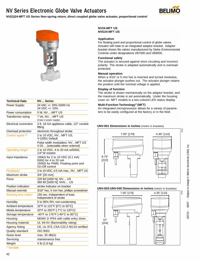
NV24-MFT USNVG24-MFT US
ApplicationFor floating point and proportional control of globe valves.Actuator will mate to an integrated adaptor bracket. Adaptorbracket shown fits valves manufactured by Siebe EnvironmentalControls under designations VB7000 and VB9000.
Functional safetyThe actuator is secured against short circuiting and incorrectpolarity. The stroke is adapted automatically and is overload-protected.
Manual operationWhen a 3/16” or 5 mm hex is inserted and turned clockwise,the actuator plunger pushes out. The actuator plunger retainsthe position until the nominal voltage is applied.
Display of functionThe stroke is shown mechanically on the adaptor bracket, andthe maximum stroke is set automatically. Under the housingcover on -MFT models is a two-colored LED status display.
Multi-Function Technology® (MFT)An integrated microprocessor allows for a variety of parame-ters to be easily configured at the factory or in the field.
Technical Data NV… SeriesPower Supply: 24 VAC +/- 20% 50/60 Hz
24 VDC +/- 10%Power consumption 5 W, NV…-MFT USTransformer sizing 7 VA, NV…-MFT US
(Class 2 power supply)
Electrical connection 3 ft, 18 GA appliance cable, 1/2" conduitfitting
Overload protection electronic throughout strokeControl signal Y* 2 to 10 VDC, NV…MFT US,
V-10001 Default Pulse width modulation, NV…MFT US V-20… (selectable when ordered)
Operating range* 2 to 10 VDC, 4 to 20 mA w/500Ω, 1/4” W resistor
Input impedance 100kΩ for 2 to 10 VDC (0.1 mA)500Ω for 4 to 20 mA 1500Ω for PWM, Floating point andOn-Off control
Feedback* 2 to 10 VDC, 0.5 mA max., NV…MFT USMaximum stroke 3/4" [20 mm]Force 225 lbf [1000 N], NV… US
360 lbf [1600 N], NVG… USPosition indication stroke indicator on bracketManual override 3/16" hex, 5 mm hex, phillips screwdriverRunning time motor* 150 sec. Independent of load,
Independent of strokeHumidity 5 to 95% RH, non-condensingAmbient temperature 32°F to 122°F [0°C to 50°C]Media temperature 20°F to 250°F [-7°C to 120°C]Storage temperature -40°F to 176°F [-40°C to 80°C]Housing NEMA 2/ IP54 with cable entry downHousing material UL 94-5V (flammability rating)Agency listing CE, UL 873, CSA C22.2 NO.24 certifiedQuality standard ISO 9001Noise level max. 35 dB(A)Servicing maintenance freeWeight 4 lb [1.8 kg]* Variable
UNV-001 Dimensions in inches (metric in brackets)
UNV-003-UNV-040 Dimensions in inches (metric in brackets)
8.75" [222]
7.05" [179] 4.35" [110]
10" [254]
7.05" [179] 4.35" [110]
D03
3D
034
®
43
J207
21 -
06/
07 -
Sub
ject
to c
hang
e ©
Bel
imo
Airc
ontro
ls (U
SA),
Inc.
1
1
NVD24-MFT USNV24-MFT USNVG24-MFT US
Blk (1) Common –
Wht (2) Hot +
Wht (3) Y Input
Grn (5) U Output Feedback Signal (+)2 to 10 VDC (–)
Line Volts
24 VAC Transformer
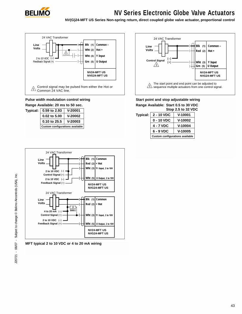
Control signal may be pulsed from either the Hot or Common 24 VAC line.
Blk (1) Common
Red (2) + Hot
Wht (3) Y1 Input, 2 to 10V
Wht (5) U Output, 2 to 10V
NV24-MFT USNVG24-MFT US
NVD24-MFT US
Control Signal (+)
2 to 10 VDC (–)Feedback Signal (+)
4 to 20 mA (–)
Line Volts
24 VAC Transformer
500Ω Ω
Blk (1) Common
Red (2) + Hot
Wht (3) Y1 Input, 2 to 10V
Wht (5) U Output, 2 to 10V
NV24-MFT USNVG24-MFT US
NVD24-MFT US
Control Signal (+)
2 to 10 VDC (–)
Feedback Signal (+)
2 to 10 VDC (–)
Line Volts
24 VAC Transformer
MFT typical 2 to 10 VDC or 4 to 20 mA wiring
Pulse width modulation control wiring
Range Available: 20 ms to 50 sec.
Typical: 0.59 to 2.93 V-20001
0.02 to 5.00 V-20002
0.10 to 25.5 V-20003Custom configurations available
Start point and stop adjustable wiring
Range Available: Start 0.5 to 30 VDCStop 2.5 to 32 VDC
Typical: 2 - 10 VDC V-10001
0 - 10 VDC V-10002
4 - 7 VDC V-10004
6 - 9 VDC V-10005Custom configurations available
1
1
NV24-MFT USNVG24-MFT US
NVD24-MFT US
Line Volts
24 VAC Transformer
The start point and end point can be adjusted to sequence multiple actuators from one control signal.
Blk (1) Common –
Wht (3) Y Input Grn (5) U Output
Red (2) Hot +
Control Signal(–)(+)
NV Series Electronic Globe Valve ActuatorsNV(G)24-MFT US Series Non-spring return, direct coupled globe valve actuator, proportional control
NV24-MFT USNVG24-MFT US
NV24-MFT USNVG24-MFT US
NV24-MFT USNVG24-MFT US
NV24-MFT USNVG24-MFT US
®
44
J207
21 -
06/
07 -
Sub
ject
to c
hang
e ©
Bel
imo
Airc
ontro
ls (U
SA),
Inc.
NV Series Electronic Globe Valve ActuatorsNV24-3 US Non-spring return, on/off, floating point
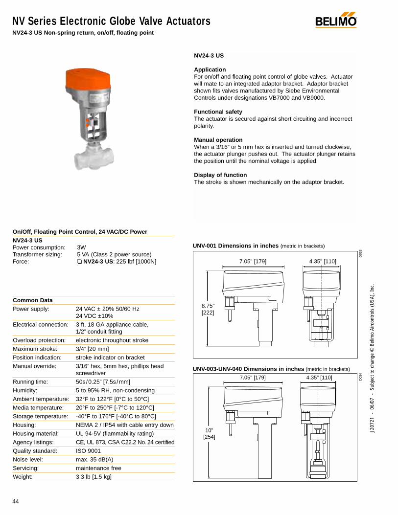
On/Off, Floating Point Control, 24 VAC/DC PowerNV24-3 USPower consumption: 3WTransformer sizing: 5 VA (Class 2 power source)Force: NV24-3 US: 225 lbf [1000N]
Common DataPower supply: 24 VAC ± 20% 50/60 Hz
24 VDC ±10%
Electrical connection: 3 ft, 18 GA appliance cable, 1/2” conduit fitting
Overload protection: electronic throughout stroke
Maximum stroke: 3/4” [20 mm]
Position indication: stroke indicator on bracket
Manual override: 3/16” hex, 5mm hex, phillips headscrewdriver
Running time: 50s/0.25” [7.5s/mm]
Humidity: 5 to 95% RH, non-condensing
Ambient temperature: 32°F to 122°F [0°C to 50°C]
Media temperature: 20°F to 250°F [-7°C to 120°C]
Storage temperature: -40°F to 176°F [-40°C to 80°C]
Housing: NEMA 2 / IP54 with cable entry down
Housing material: UL 94-5V (flammability rating)
Agency listings: CE, UL 873, CSA C22.2 No. 24 certified
Quality standard: ISO 9001
Noise level: max. 35 dB(A)
Servicing: maintenance free
Weight: 3.3 lb [1.5 kg]
NV24-3 US
ApplicationFor on/off and floating point control of globe valves. Actuatorwill mate to an integrated adaptor bracket. Adaptor bracketshown fits valves manufactured by Siebe EnvironmentalControls under designations VB7000 and VB9000.
Functional safetyThe actuator is secured against short circuiting and incorrectpolarity.
Manual operationWhen a 3/16” or 5 mm hex is inserted and turned clockwise,the actuator plunger pushes out. The actuator plunger retainsthe position until the nominal voltage is applied.
Display of functionThe stroke is shown mechanically on the adaptor bracket.
UNV-001 Dimensions in inches (metric in brackets)
UNV-003-UNV-040 Dimensions in inches (metric in brackets)
8.75" [222]
7.05" [179] 4.35" [110]
10" [254]
7.05" [179] 4.35" [110] D03
4D
033
®
45
J207
21 -
06/
07 -
Sub
ject
to c
hang
e ©
Bel
imo
Airc
ontro
ls (U
SA),
Inc.
NV Series Electronic Globe Valve ActuatorsNV24-3 US Non-spring return, on/off, floating point
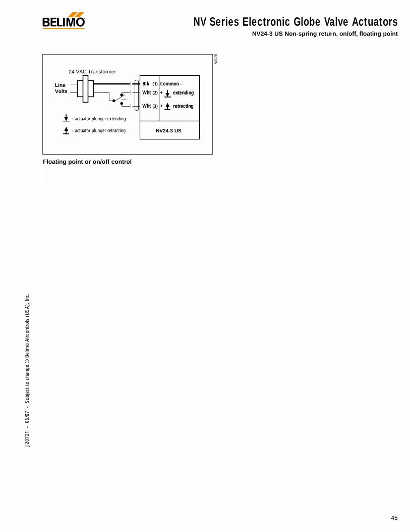
Floating point or on/off control
W12
8
Blk Common –
+ extending
+ retracting
(1)
(2)
(3)
Wht
Wht
NV24-3 USNVD24-3 US
= actuator plunger extending
= actuator plunger retracting
Line Volts
24 VAC Transformer
NV24-3 US
NV Series Electronic Globe Valve ActuatorsNVF… Series Spring return fail safe, direct coupled globe valve actuator,on/off, floating point, proportional control
®
46
J207
21 -
06/
07 -
Sub
ject
to c
hang
e ©
Bel
imo
Airc
ontro
ls (U
SA),
Inc.
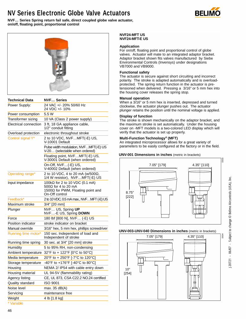
NVF24-MFT USNVF24-MFT-E US
ApplicationFor on/off, floating point and proportional control of globevalves. Actuator will mate to an integrated adaptor bracket.Adaptor bracket shown fits valves manufactured by SiebeEnvironmental Controls (Invensys) under designationsVB7000 and VB9000.
Functional safetyThe actuator is secure against short circuiting and incorrectpolarity. The stroke is adapted automatically and is overload-protected. The spring return function in the actuator is pre-tensioned when delivered. Pressing a 3/16” or 5 mm hex intothe housing cover releases the spring stop.
Manual operationWhen a 3/16” or 5 mm hex is inserted, depressed and turnedclockwise, the actuator plunger pushes out. The actuatorplunger retains the position until the nominal voltage is applied.
Display of functionThe stroke is shown mechanically on the adaptor bracket, andthe maximum stroke is set automatically. Under the housingcover on -MFT models is a two-colored LED display which willverify that the actuator is set up properly.
Multi-Function Technology® (MFT)An integrated microprocessor allows for a great variety ofparameters to be easily configured at the factory or in the field.
Technical Data NVF… SeriesPower Supply: 24 VAC +/- 20% 50/60 Hz
24 VDC +/- 10%Power consumption 5.5 WTransformer sizing 10 VA (Class 2 power supply)Electrical connection 3 ft, 18 GA appliance cable,
1/2" conduit fittingOverload protection electronic throughout strokeControl signal Y* 2 to 10 VDC, NVF…MFT(-E) US,
V-10001 Default Pulse width modulation, NVF…MFT(-E) USV-20… (selectable when ordered)Floating point, NVF…MFT(-E) US, V-30001 Default (when ordered)On-Off, NVF…(-E) US, V-40002 Default (when ordered)
Operating range* 2 to 10 VDC, 4 to 20 mA (w/500Ω, 1/4 W resistor), NVF…MFT(-E) US
Input impedance 100kΩ for 2 to 10 VDC (0.1 mA)500Ω for 4 to 20 mA 1500Ω for PWM, Floating point and On-Off control
Feedback* 2 to 10 VDC, 0.5 mA max., NVF…MFT(-E) USMaximum stroke 3/4" [20 mm]Plunger NVF… US, Spring UP
NVF…-E US, Spring DOWNForce 180 lbf [800 N], NVF… (-E) USPosition indicator stroke indicator on bracketManual override 3/16" hex, 5 mm hex, phillips screwdriverRunning time motor* 150 sec. Independent of load and
Independent of strokeRunning time spring 30 sec. at 3/4" [20 mm] strokeHumidity 5 to 95% RH, non-condensingAmbient temperature 32°F to + 122°F [0°C to 50°C]Media temperature 20°F to + 250°F [-7°C to 120°C]Storage temperature -40°F to +176°F [-40°C to 80°C]Housing NEMA 2/ IP54 with cable entry downHousing material UL 94-5V (flammability rating)Agency listing CE, UL 873, CSA C22.2 NO.24 certifiedQuality standard ISO 9001Noise level max. 35 dB(A)Servicing maintenance freeWeight 4 lb [1.8 kg]* Variable
UNV-001 Dimensions in inches (metric in brackets)
UNV-003-UNV-040 Dimensions in inches (metric in brackets)
8.75" [222]
7.05" [179] 4.35" [110]
10" [254]
7.05" [179] 4.35" [110] D03
4D
033
®
47
J207
21 -
06/
07 -
Sub
ject
to c
hang
e ©
Bel
imo
Airc
ontro
ls (U
SA),
Inc.
1
1
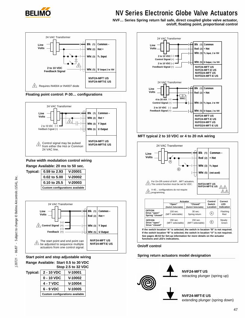
NVF24-MFT USNVF24-MFT-E USNVFD24-MFT USNVFD24-MFT-E US
Line Volts
2 to 10 VDC Feedback Signal
24 VAC Transformer
Requires IN4004 or IN4007 diode
Blk (1) Common –
Wht (2) Hot +
Wht (3) Y1 Input
Wht (5) U Output 2 to 10V
Control Signal (+)
2 to 10 VDC (–)
Feedback Signal (+)
2 to 10 VDC (–)
Line Volts
24 VAC Transformer
24 VAC Transformer
Blk (1) Common
Red (2) + Hot
Wht (3) Y1 Input, 2 to 10V
Wht (5) U Output, 2 to 10V
NVF24-MFT USNVF24-MFT-E USNVFD24-MFT USNVFD24-MFT-E US
Line Volts
Control Signal (+)
2 to 10 VDC (–)Feedback Signal (+)
4 to 20 mA (–) 500Ω Ω
Blk (1) Common
Red (2) + Hot
Wht (3) Y1 Input, 2 to 10V
Wht (5) U Output, 2 to 10V
NVF24-MFT USNVF24-MFT-E USNVFD24-MFT USNVFD24-MFT-E US
Floating point control: P-30… configurations
Spring return actuators model designation
NVF24-MFT USretracting plunger (spring up)
NVF24-MFT-E USextending plunger (spring down)
MFT typical 2 to 10 VDC or 4 to 20 mA wiring
24 VAC Transformer
Line Volts
Blk (1) Common –
Red (2) + Hot
Wht (3) Y1 Input
Wht (5) (not used)
NVFD24 US NVFD24-E USNVF24-MFT (-E) US NVFD24-MFT (-E) US
1 2
1 2
For On-Off control of NVF…MFT actuators. The control function must be set for VDC.
V-40… configurations do not require programming.
Actuator Control Correct “Open” “Closed” Switch LED (Switch Selectable) (Switch Selectable) Location Indication
150 sec. 30 sec. Flashing (MFT selectable) Spring return Red
150 sec. 150 sec. Steady (MFT selectable) (MFT selectable) Green
1
2
A
B
OFF/ON Drive “open" Spring “closed”
OFF/ON Drive “open” Drive “closed”
A
B
If the switch location “A” is selected, the switch in location “B” is not required. If the switch location “B” is selected, the switch in location “A” is not required.
1
1
NVF24-MFT USNVF24-MFT-E USNVFD24-MFT USNVFD24-MFT-E US
Blk (1) Common –
Wht (2) Hot +
Wht (3) Y Input
Wht (5) U Output Feedback Signal (+)2 to 10 VDC (–)
Line Volts
24 VAC Transformer
Control signal may be pulsed from either the Hot or Common 24 VAC line.
1
1
NVF24-MFT USNVF24-MFT-E USNVFD24-MFT USNVFD24-MFT-E US
Blk (1) Common –
Red (2) Hot +
Wht (3) Y Input
Wht (5) U Output
Control Signal (+)
Feedback (+)
(–)
(–)
Line Volts
24 VAC Transformer
The start point and end point can be adjusted to sequence multiple actuators from one control signal.
Pulse width modulation control wiring
Range Available: 20 ms to 50 sec.
Typical: 0.59 to 2.93 V-20001
0.02 to 5.00 V-20002
0.10 to 25.5 V-20003Custom configurations available
Start point and stop adjustable wiring
Range Available: Start 0.5 to 30 VDCStop 2.5 to 32 VDC
Typical: 2 - 10 VDC V-10001
0 - 10 VDC V-10002
4 - 7 VDC V-10004
6 - 9 VDC V-10005Custom configurations available
On/off control
If the switch location “A” is selected, the switch in location “B” is not required.If the switch location “B” is selected, the switch in location “A” is not required.See pages 48-53 for Set-up information for more details on the actuator functions and LED’s indications.
NV Series Electronic Globe Valve ActuatorsNVF… Series Spring return fail safe, direct coupled globe valve actuator,
on/off, floating point, proportional control
NVF24-MFT USNVF24-MFT-E US
NVF24-MFT USNVF24-MFT-E US
NVF24-MFT USNVF24-MFT-E US
NVF24-MFT USNVF24-MFT-E US
UNV Retrofit Components ®
J207
21 -
06/
07 -
Sub
ject
to c
hang
e ©
Bel
imo
Airc
ontro
ls (U
SA),
Inc.
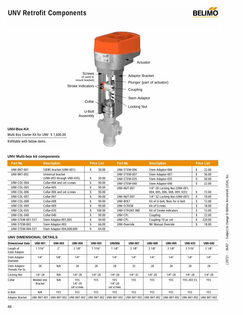
UNV Multi-box kit components
Part No. Description Price List
UNV-BKT-001 SIEBE bracket (UNV-001) $ 30.00UNV-BKT-002 Universal bracket
(UNV-003 through UNV-035) $ 30.00UNV-COL-004 Collar-004 and set screws $ 90.00UNV-COL-005 Collar-005 $ 90.00UNV-COL-006 Collar-006 and set screws $ 90.00UNV-COL-007 Collar-007 $ 90.00UNV-COL-008 Collar-008 $ 90.00UNV-COL-009 Collar-009 $ 90.00UNV-COL-035 Collar-035 $ 100.00UNV-COL-040 Collar-040 $ 90.00UNV-STEM-001-SET Stem Adaptor-001,005 $ 44.00UNV-STEM-003 Stem Adaptor-003 $ 66.00UNV-STEM-004-SET Stem Adaptor-004,008,009 $ 64.00
Part No. Description Price List
UNV-STEM-006 Stem Adaptor-006 $ 22.00UNV-STEM-007 Stem Adaptor-007 $ 36.00UNV-STEM-035 Stem Adaptor-035 $ 30.00UNV-STEM-040 Stem Adaptor-040 $ 22.00UNV-NUT-001 1/4”-28 Locking Nut (UNV-001,
004, 005, 006, 008, 009, 035) $ 72.00UNV-NUT-007 1/4”-32 Locking Nut (UNV-007) $ 18.00UNV-BOLT Kit of U-bolt, Nuts for U-bolt $ 12.00UNV-SCREW Kit of Screws $ 18.00UNV-STROKE IND Kit of Stroke indicators $ 12.00UNV-CPL Coupling $ 22.00UNV-CPL Coupling-10 pc set $ 220.00UNV-Override NV Manual Override $ 18.00
Actuator
Adaptor Bracket
Plunger (part of actuator)
Coupling
Stem Adaptor
Locking Nut
Screws(4 used to
mount bracket)
Stroke Indicators
Collar
U-Bolt Assembly
UNV DIMENSIONAL DETAILS
Dimensional Data UNV-001 UNV-003 UNV-004 UNV-005 UNV006 UNV-007 UNV-008 UNV-009 UNV-035 UNV-040
Length of 1 7/16” 2” 2 1/8” 1 7/16” 1 1/8” 2 1/8” 2 1/8” 2 1/8” 3 7/16” 2 1/8”Stem Adaptor
Stem Adaptor 1/4” 5/8” 1/4” 1/4” 1/4” 1/4” 1/4” 1/4” 1/4” 1/4”Diameter
Stem Adaptor- 28 N/A 28 28 28 32 28 28 28 28Threads Per In.
Locking Nut 1/4”-28 N/A 1/4”-28 1/4”-28 1/4”-28 1/4”-32 1/4”-28 1/4”-28 1/4”-28 1/4”-28
Collar Molded into N/A YES YES YES YES YES YES YES-303 SS YESBracket 1/4”-20 1/4”-20
set screws set screws
U-Bolt N/A YES YES YES YES YES YES YES YES YES
Adaptor Bracket UNV-BKT-001 UNV-BKT-002 UNV-BKT-002 UNV-BKT-002 UNV-BKT-002 UNV-BKT-002 UNV-BKT-002 UNV-BKT-002 UNV-BKT-002 UNV-BKT-002
48
UNV-Box-Kit
Multi Box Starter Kit for UNV $ 1,600.00
Refillable with below items.
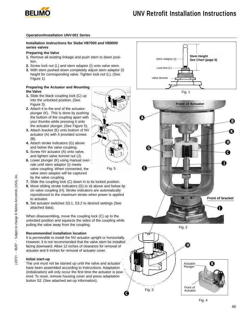
®
49
J207
21 -
06/
07 -
Sub
ject
to c
hang
e ©
Bel
imo
Airc
ontro
ls (U
SA),
Inc.
UNV Retrofit Installation Instructions
Installation instructions for Siebe VB7000 and VB9000series valves
Preparing the Valve1. Remove all existing linkage and push stem to down posi-
tion.2. Screw lock nut (L) and stem adaptor (I) onto valve stem.3. With stem pushed down completely adjust stem adaptor (I)
height for corresponding valve. Tighten lock nut (L). (SeeFigure 1).
Preparing the Actuator and Mountingthe Valve1. Slide the black coupling lock (C) up
into the unlocked position. (SeeFigure 3).
2. Attach it to the end of the actuatorplunger (K). This is done by pushingthe bottom of the coupling apart withyour thumbs while pressing it ontothe actuator plunger. (See Figure 5).
3. Attach bracket (E) onto bottom of NVactuator (A) with 4 provided screws(B).
4. Attach stroke indicators (G) aboveand below the valve coupling.
5. Screw NV actuator (A) onto valve,and tighten valve bonnet nut (J).
6. Lower plunger (K) using manual over-ride until stem adaptor (I) meetsvalve coupling. When connected, thevalve stem adaptor will be capturedby the valve coupling.
7. Slide the coupling lock (C) down in to its locked position.8. Move sliding stroke indicators (G) to sit above and below lip
on valve coupling (H). Stroke indicators are automaticallyrepositioned to the maximum stroke when power is appliedto actuator.
9. Set actuator switches S3.1, S3.2 to desired settings (Seeattached data).
When disassembling, move the coupling lock (C) up to theunlocked position and squeeze the sides of the coupling whilepulling the valve away from the coupling.
Recommended installation locationIt is permissible to install the NV actuator upright or horizontally.However, it is not recommended that the valve stem be installedfacing downward. Allow 12 inches of clearance for removal ofactuator and 6 inches for removal of actuator cover.
Initial start-upThe unit must not be started up until the valve and actuatorhave been assembled according to instructions. Adaptation(initialization) will only occur the first time the actuator is pow-ered. To reset, remove housing cover and press adaptationbutton S2. (See attached set-up information).
A
K
E
GH
B
C
Stem HeightAdjustment
lock-nut
stem adaptor
valvebonnetnut
Fig. 1
I
J
Fig. 4
H
Stem HeightSee Chart (page 6)
Front of Actuator
Front of bracket
Stem Adaptor (I)
Lock-Nut (L)
Valve Bonnet
Actuator Plunger
K
Front ofActuator
Operation/Installation UNV-001 Series
Fig. 2
Fig. 5
CFig. 3
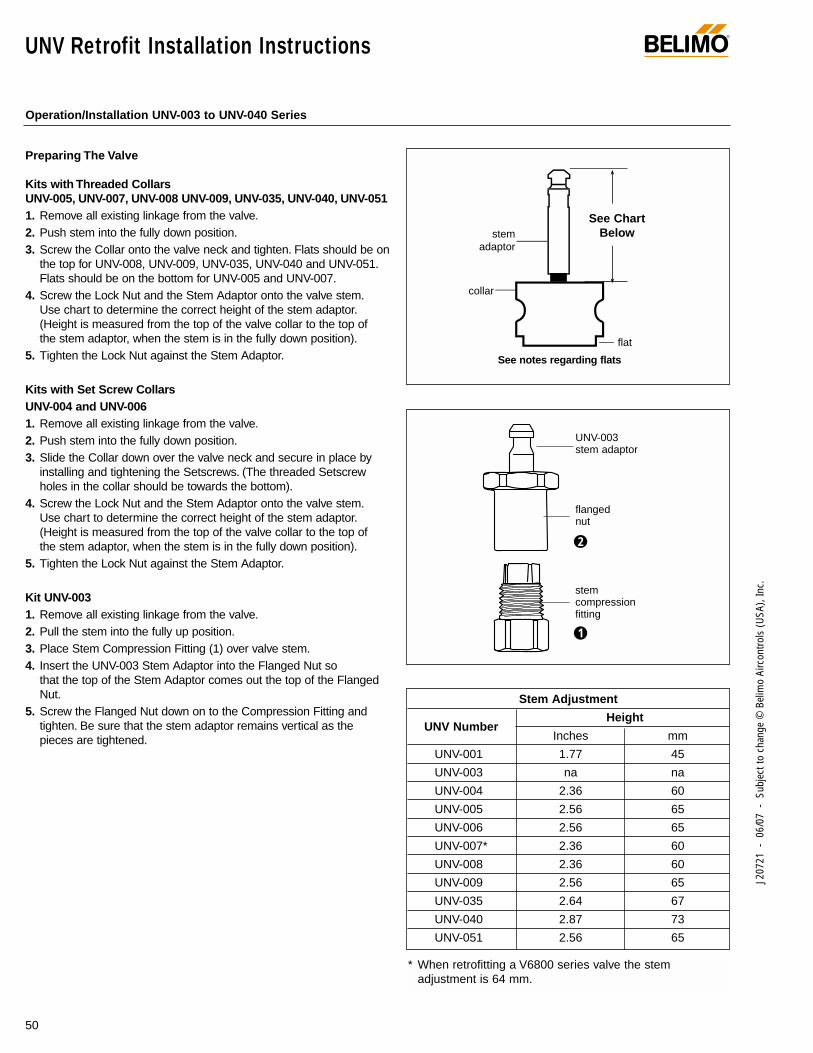
®
50
J207
21 -
06/
07 -
Sub
ject
to c
hang
e ©
Bel
imo
Airc
ontro
ls (U
SA),
Inc.
Preparing The Valve
Kits with Threaded CollarsUNV-005, UNV-007, UNV-008 UNV-009, UNV-035, UNV-040, UNV-0511. Remove all existing linkage from the valve.2. Push stem into the fully down position.3. Screw the Collar onto the valve neck and tighten. Flats should be on
the top for UNV-008, UNV-009, UNV-035, UNV-040 and UNV-051.Flats should be on the bottom for UNV-005 and UNV-007.
4. Screw the Lock Nut and the Stem Adaptor onto the valve stem.Use chart to determine the correct height of the stem adaptor.(Height is measured from the top of the valve collar to the top ofthe stem adaptor, when the stem is in the fully down position).
5. Tighten the Lock Nut against the Stem Adaptor.
Kits with Set Screw CollarsUNV-004 and UNV-0061. Remove all existing linkage from the valve.2. Push stem into the fully down position.3. Slide the Collar down over the valve neck and secure in place by
installing and tightening the Setscrews. (The threaded Setscrewholes in the collar should be towards the bottom).
4. Screw the Lock Nut and the Stem Adaptor onto the valve stem.Use chart to determine the correct height of the stem adaptor.(Height is measured from the top of the valve collar to the top ofthe stem adaptor, when the stem is in the fully down position).
5. Tighten the Lock Nut against the Stem Adaptor.
Kit UNV-0031. Remove all existing linkage from the valve.2. Pull the stem into the fully up position.3. Place Stem Compression Fitting (1) over valve stem.4. Insert the UNV-003 Stem Adaptor into the Flanged Nut so
that the top of the Stem Adaptor comes out the top of the FlangedNut.
5. Screw the Flanged Nut down on to the Compression Fitting andtighten. Be sure that the stem adaptor remains vertical as thepieces are tightened.
UNV Retrofit Installation Instructions
UNV-003stem adaptor
Stem HeightAdjustment
collar
stem adaptor
flat
See Chart Belowstem
adaptor
collar
flat
stemcompressionfitting
flanged nut
1
2
See notes regarding flats
Stem Adjustment
UNV NumberHeight
Inches mm
UNV-001 1.77 45
UNV-003 na na
UNV-004 2.36 60
UNV-005 2.56 65
UNV-006 2.56 65
UNV-007* 2.36 60
UNV-008 2.36 60
UNV-009 2.56 65
UNV-035 2.64 67
UNV-040 2.87 73
UNV-051 2.56 65
* When retrofitting a V6800 series valve the stem adjustment is 64 mm.
Operation/Installation UNV-003 to UNV-040 Series
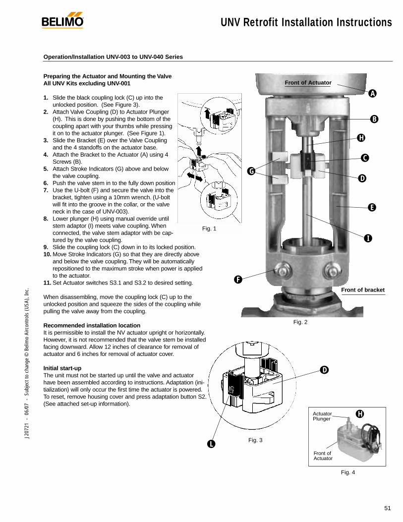
®
51
J207
21 -
06/
07 -
Sub
ject
to c
hang
e ©
Bel
imo
Airc
ontro
ls (U
SA),
Inc.
UNV Retrofit Installation Instructions
Preparing the Actuator and Mounting the ValveAll UNV Kits excluding UNV-001
1. Slide the black coupling lock (C) up into theunlocked position. (See Figure 3).
2. Attach Valve Coupling (D) to Actuator Plunger(H). This is done by pushing the bottom of thecoupling apart with your thumbs while pressingit on to the actuator plunger. (See Figure 1).
3. Slide the Bracket (E) over the Valve Couplingand the 4 standoffs on the actuator base.
4. Attach the Bracket to the Actuator (A) using 4Screws (B).
5. Attach Stroke Indicators (G) above and belowthe valve coupling.
6. Push the valve stem in to the fully down position7. Use the U-bolt (F) and secure the valve into the
bracket, tighten using a 10mm wrench. (U-boltwill fit into the groove in the collar, or the valveneck in the case of UNV-003).
8. Lower plunger (H) using manual override untilstem adaptor (I) meets valve coupling. Whenconnected, the valve stem adaptor with be cap-tured by the valve coupling.
9. Slide the coupling lock (C) down in to its locked position.10. Move Stroke Indicators (G) so that they are directly above
and below the valve coupling. They will be automatically repositioned to the maximum stroke when power is applied to the actuator.
11. Set Actuator switches S3.1 and S3.2 to desired setting.
When disassembling, move the coupling lock (C) up to theunlocked position and squeeze the sides of the coupling whilepulling the valve away from the coupling.
Recommended installation locationIt is permissible to install the NV actuator upright or horizontally.However, it is not recommended that the valve stem be installedfacing downward. Allow 12 inches of clearance for removal ofactuator and 6 inches for removal of actuator cover.
Initial start-upThe unit must not be started up until the valve and actuatorhave been assembled according to instructions. Adaptation (ini-tialization) will only occur the first time the actuator is powered.To reset, remove housing cover and press adaptation button S2.(See attached set-up information).
Fig. 4
Fig. 3
D
A
B
D
H
C
F
G
E
I
L
Front of bracket
Front of Actuator
Operation/Installation UNV-003 to UNV-040 Series
Fig. 2
Actuator Plunger
H
Front ofActuator
Fig. 1
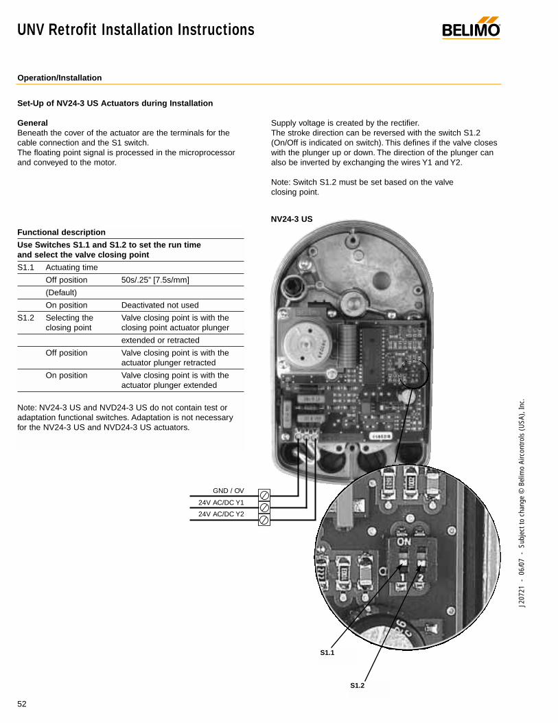
®
52
J207
21 -
06/
07 -
Sub
ject
to c
hang
e ©
Bel
imo
Airc
ontro
ls (U
SA),
Inc.
UNV Retrofit Installation Instructions
Operation/Installation
NV24-3 US
S1.2
S1.1
Functional description
Use Switches S1.1 and S1.2 to set the run timeand select the valve closing point
S1.1 Actuating time
Off position 50s/.25” [7.5s/mm]
(Default)
On position Deactivated not used
S1.2 Selecting the Valve closing point is with theclosing point closing point actuator plunger
extended or retracted
Off position Valve closing point is with theactuator plunger retracted
On position Valve closing point is with theactuator plunger extended
Note: NV24-3 US and NVD24-3 US do not contain test oradaptation functional switches. Adaptation is not necessaryfor the NV24-3 US and NVD24-3 US actuators.
Set-Up of NV24-3 US Actuators during Installation
GeneralBeneath the cover of the actuator are the terminals for thecable connection and the S1 switch.The floating point signal is processed in the microprocessorand conveyed to the motor.
Supply voltage is created by the rectifier.The stroke direction can be reversed with the switch S1.2(On/Off is indicated on switch). This defines if the valve closeswith the plunger up or down. The direction of the plunger canalso be inverted by exchanging the wires Y1 and Y2.
Note: Switch S1.2 must be set based on the valve closing point.
GND / OV
24V AC/DC Y1
24V AC/DC Y2
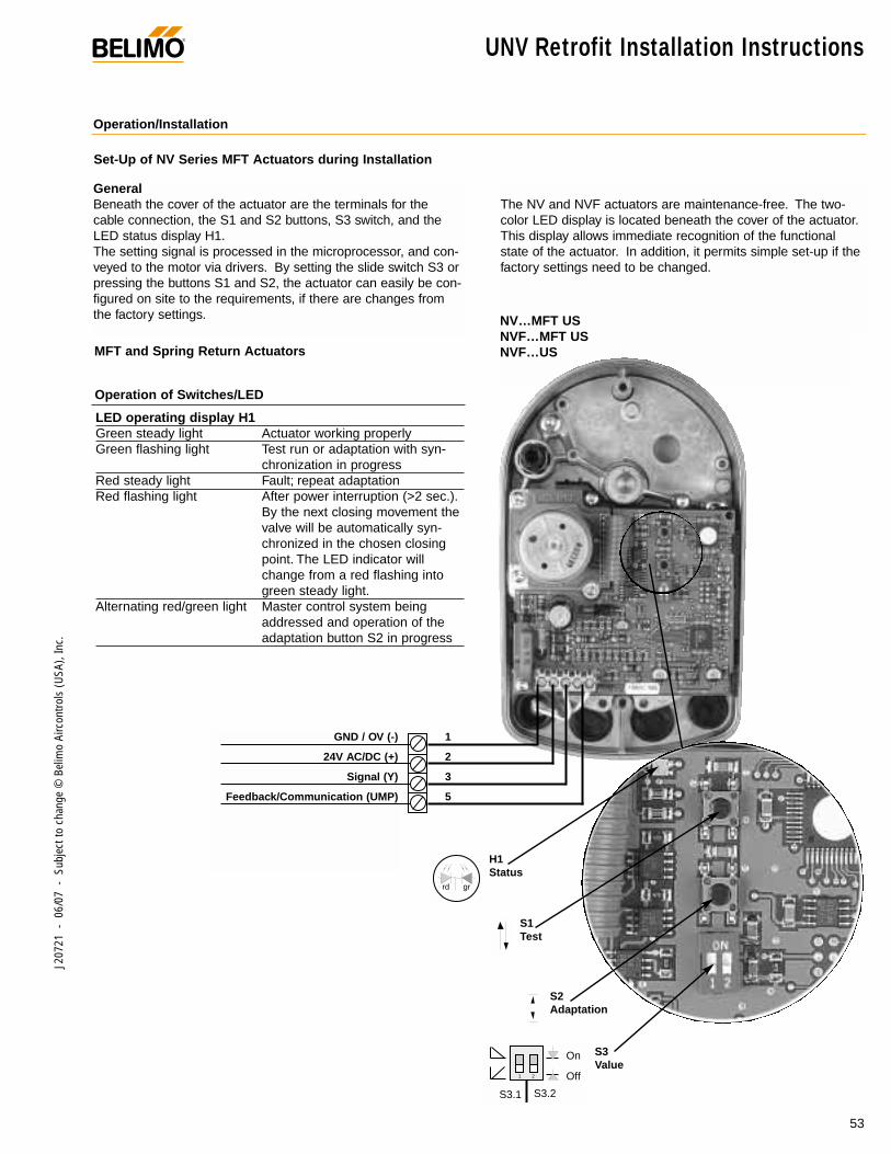
®
53
J207
21 -
06/
07 -
Sub
ject
to c
hang
e ©
Bel
imo
Airc
ontro
ls (U
SA),
Inc.
GeneralBeneath the cover of the actuator are the terminals for thecable connection, the S1 and S2 buttons, S3 switch, and theLED status display H1.The setting signal is processed in the microprocessor, and con-veyed to the motor via drivers. By setting the slide switch S3 orpressing the buttons S1 and S2, the actuator can easily be con-figured on site to the requirements, if there are changes fromthe factory settings.
1 2
On
Off
S3.1 S3.2
rd gr
MFT and Spring Return Actuators
LED operating display H1Green steady light Actuator working properlyGreen flashing light Test run or adaptation with syn-
chronization in progressRed steady light Fault; repeat adaptationRed flashing light After power interruption (>2 sec.).
By the next closing movement thevalve will be automatically syn-chronized in the chosen closingpoint. The LED indicator willchange from a red flashing intogreen steady light.
Alternating red/green light Master control system being addressed and operation of the adaptation button S2 in progress
Operation of Switches/LED
The NV and NVF actuators are maintenance-free. The two-color LED display is located beneath the cover of the actuator.This display allows immediate recognition of the functionalstate of the actuator. In addition, it permits simple set-up if thefactory settings need to be changed.
Set-Up of NV Series MFT Actuators during Installation
NV…MFT USNVF…MFT USNVF…US
S1Test
H1Status
S2Adaptation
S3Value
GND / OV (-)
24V AC/DC (+)
Signal (Y)
Feedback/Communication (UMP)
1
2
3
5
Operation/Installation
UNV Retrofit Installation Instructions
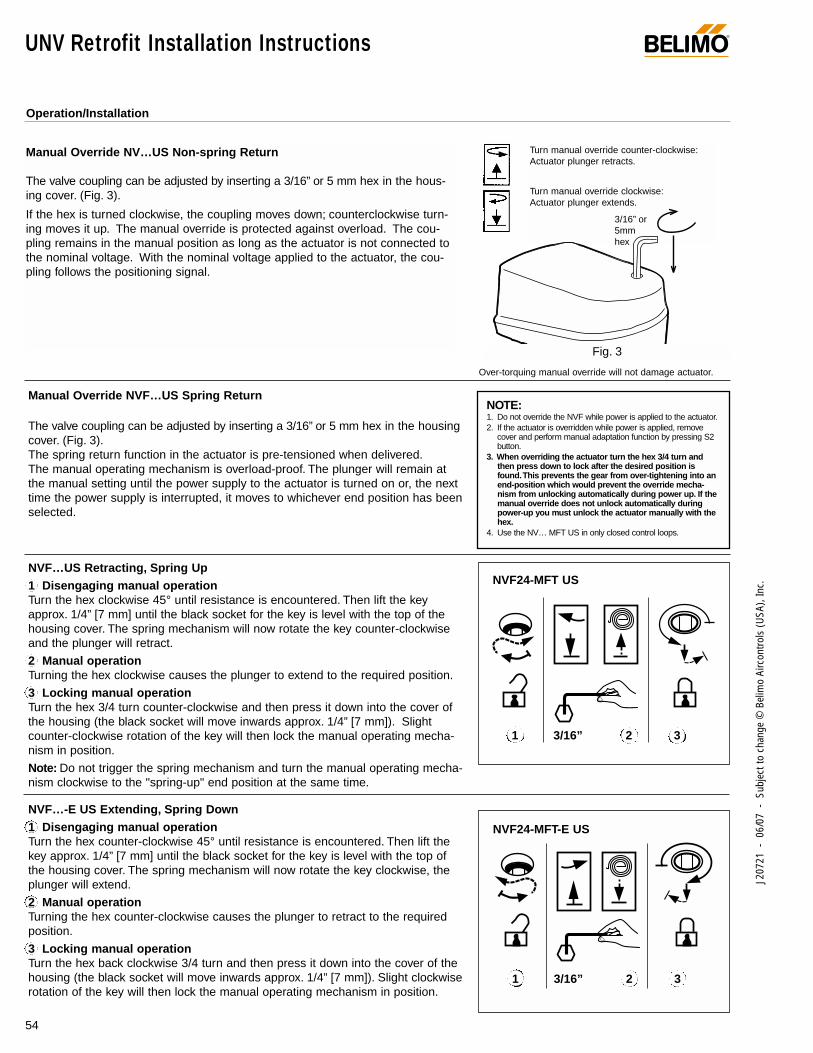
Manual Override NV…US Non-spring Return
The valve coupling can be adjusted by inserting a 3/16” or 5 mm hex in the hous-ing cover. (Fig. 3).
If the hex is turned clockwise, the coupling moves down; counterclockwise turn-ing moves it up. The manual override is protected against overload. The cou-pling remains in the manual position as long as the actuator is not connected tothe nominal voltage. With the nominal voltage applied to the actuator, the cou-pling follows the positioning signal.
Turn manual override counter-clockwise:Actuator plunger retracts.
Turn manual override clockwise:Actuator plunger extends.
3/16” or5mm hex
Over-torquing manual override will not damage actuator.
Fig. 3
The valve coupling can be adjusted by inserting a 3/16” or 5 mm hex in the housingcover. (Fig. 3).The spring return function in the actuator is pre-tensioned when delivered.The manual operating mechanism is overload-proof. The plunger will remain atthe manual setting until the power supply to the actuator is turned on or, the nexttime the power supply is interrupted, it moves to whichever end position has beenselected.
NVF…US Retracting, Spring Up1 Disengaging manual operation Turn the hex clockwise 45° until resistance is encountered. Then lift the keyapprox. 1/4” [7 mm] until the black socket for the key is level with the top of thehousing cover. The spring mechanism will now rotate the key counter-clockwiseand the plunger will retract.
2 Manual operation Turning the hex clockwise causes the plunger to extend to the required position.
3 Locking manual operation Turn the hex 3/4 turn counter-clockwise and then press it down into the cover ofthe housing (the black socket will move inwards approx. 1/4” [7 mm]). Slightcounter-clockwise rotation of the key will then lock the manual operating mecha-nism in position.
Note: Do not trigger the spring mechanism and turn the manual operating mecha-nism clockwise to the "spring-up" end position at the same time.
NVF…-E US Extending, Spring Down1 Disengaging manual operation Turn the hex counter-clockwise 45° until resistance is encountered. Then lift thekey approx. 1/4” [7 mm] until the black socket for the key is level with the top ofthe housing cover. The spring mechanism will now rotate the key clockwise, theplunger will extend.
2 Manual operation Turning the hex counter-clockwise causes the plunger to retract to the requiredposition.
3 Locking manual operation Turn the hex back clockwise 3/4 turn and then press it down into the cover of thehousing (the black socket will move inwards approx. 1/4” [7 mm]). Slight clockwiserotation of the key will then lock the manual operating mechanism in position.
Manual Override NVF…US Spring Return
NVF24-MFT US
NVF24-MFT-E US
1 33/16” 2
1 33/16” 2
NOTE:1. Do not override the NVF while power is applied to the actuator.2. If the actuator is overridden while power is applied, remove
cover and perform manual adaptation function by pressing S2button.
3. When overriding the actuator turn the hex 3/4 turn andthen press down to lock after the desired position isfound.This prevents the gear from over-tightening into anend-position which would prevent the override mecha-nism from unlocking automatically during power up. If themanual override does not unlock automatically duringpower-up you must unlock the actuator manually with thehex.
4. Use the NV… MFT US in only closed control loops.
Operation/Installation
®
54
J207
21 -
06/
07 -
Sub
ject
to c
hang
e ©
Bel
imo
Airc
ontro
ls (U
SA),
Inc.
UNV Retrofit Installation Instructions
®
55
J207
21 -
06/
07 -
Sub
ject
to c
hang
e ©
Bel
imo
Airc
ontro
ls (U
SA),
Inc.
Electronic Globe Valves
S1 Test The valve performs full stroke at mini-mum running time and checks theadapted stroke.
S2 Adaptation The stroke effected (between the twomechanical end-stops of the valve) isacquired as 100% stroke and storedin the microprocessor.The controlsignal and running time are thenmatched to this 100% stroke.
S3 Setting the direction of stroke and selecting the closing point
The S1 button makes it simple to check the wiring and overallfunctioning of the actuator. The first time voltage is applied, thestroke is adapted automatically. Independently of this, an adap-tation can be repeated as necessary by pressing button S2.Actuator will not do an adaptation after each power loss.
Functional description NV24-MFT US, NVF… US
Note: It is very important to set Switches S3.1 and S3.2 toensure proper valve operation.
1. Determine if the valve body is STEM UP CLOSED or STEMUP OPEN. In other words, when is the valve closed fromPorts A to AB– when the stem is up or down?
If the valve is STEM UP OPEN – set Switch S3.2 to the ONposition
If the valve is STEM UP CLOSED – set Switch S3.2 to theOFF position
By setting this switch, the actuator will be able to recognizeits closing point during the ADAPTATION process.
2. Determine if you would like to valve to be Reverse or DirectActing.
Direct Acting: if the valve should be CLOSED at minimumcontrol signal – set Switch 3.1 to the OFF position.
Using this setting, the valve will be CLOSED at minimumcontrol signal and will OPEN as the control signal increases.EX: Closed at 0 Volt signal and Open at 10 Volt signal.
Reverse Acting: if the valve should be OPEN at 2 Volts (orminimum control signal) – set Switch 3.1 to the ON position.
Using this setting, the valve will be OPEN at minimum controlsignal and will CLOSE as the control signal increases. EX:Closed at 10 Volt signal and Open at 2 Volt signal.
NOTE: The Feedback signal (Wire 5) of the NV Series actuatorwill follow the closing point of the valve- not the input controlsignal. In other words, the feedback will always read 2 Voltswhen the valve is closed regardless if the input control signalis set for Reverse or Direct Acting.
EXAMPLES
S3.1 OFF At 2 Volts, the valve is closedS3.2 OFF The valve closing point is STEM UP
CLOSED.
Result of Input Signal and Feedback Signal: The valve will beclosed at 2 Volts and will open as the actuator drives down. Thecontrol signal will read 2 Volts at the closed point and 10 Volts atthe fully open point. The feedback will read 2 Volts at the closedpoint and 10 Volts at the fully open point.
S3.1 ON At 2 Volts, the valve is open.S3.2 OFF The valve closing point is STEM UP
CLOSED.
Result of Input Signal and Feedback Signal: The valve will be fullyopen at 2 Volts and will close as the actuator retracts. The controlsignal will read 10 Volts at the closed point and 2 Volts at the fullyopen point. The feedback will read 2 Volts at the closed point and10 Volts at the fully open point.
S3.1 OFF At 2 Volts, the valve is closedS3.2 ON The valve closing point is STEM
DOWN CLOSED.
Result of Input Signal and Feedback Signal: The valve will beclosed at 2 Volts and will open as the actuator retracts. The con-trol signal will read 2 Volts at the closed point and 10 Volts at thefully open point. The feedback will read 2 Volts at the closed pointand 10 Volts at the fully open point.
S3.1 ON At 2 Volts, the valve is open.S3.2 ON The valve closing point is STEM
DOWN CLOSED.
Result of Input Signal and Feedback Signal: The valve will beopen at 2 Volts and will close as the actuator drives down. Thecontrol signal will read 10 Volts at the closed point and 2 Volts atthe fully open point. The feedback will read 2 Volts at the closedpoint and 10 Volts at the fully open point.
Set-Up of S3 switches
Operation/Installation
The stroke direction can be adjusted to be reverse or directacting. Under the factory setting, the stroke increases as thesetting signal increases. Depending upon the type of valve(NO/NC), the closing point (stroke = 0%) can be chosen withthe valve stem retracted or extended.
S3.1 Direction of stroke The direction of stroke is inverted in rela-tion to the control signal
Off position Control signal = 0% corresponding to 0% stroke
On position Control signal = 100% corresponding to 0% stroke
S3.2 Selecting the This is the closing point of the valve. This closing point is dependent on the valve body-not the
actuator. This setting must be correct for proper operation of the actuator.
Off position Valve is stem up closed.(Flow from A to AB).
On position Valve is stem down closed.(Flow from A to AB).

Assembly Sequence for Existing Valves
UGLK/UGSP Series Globe Valve Retrofit SystemRetrofitting STYLE 1 Globe Valves Typical for Siebe\Invensys\Barber Colman
®
56
J207
21 -
06/
07 -
Sub
ject
to c
hang
e ©
Bel
imo
Airc
ontro
ls (U
SA),
Inc.
A
C
D
F
B
E
Follow these steps to properly assemble STYLE 1 type globe valves to the retrofit linkage.Reference the step-by-step photos to help guide you through the assembly process.
The valve should be stripped down to its basic form, asshown. Remove all other linkage components before startingthe assembly sequence shown below. The linkage compo-nents have been designed to attach to the valve in this state,rather than to any existing hardware. Note that this style valvehas a permanently attached bonnet nut which rotates freely,but does not come off the valve itself.
STEP 1) Assemble the supplied stem nut (E) to the valvestem, and thread at least 10 - 12 turns down onto the stem.
STEP 2) Attach the rack assembly (F), which may or may notinclude an extension or adapter, onto the valve stem. Threadthe assembly as far down onto the valve stem as possible,until you contact the previously attached valve stem nut.
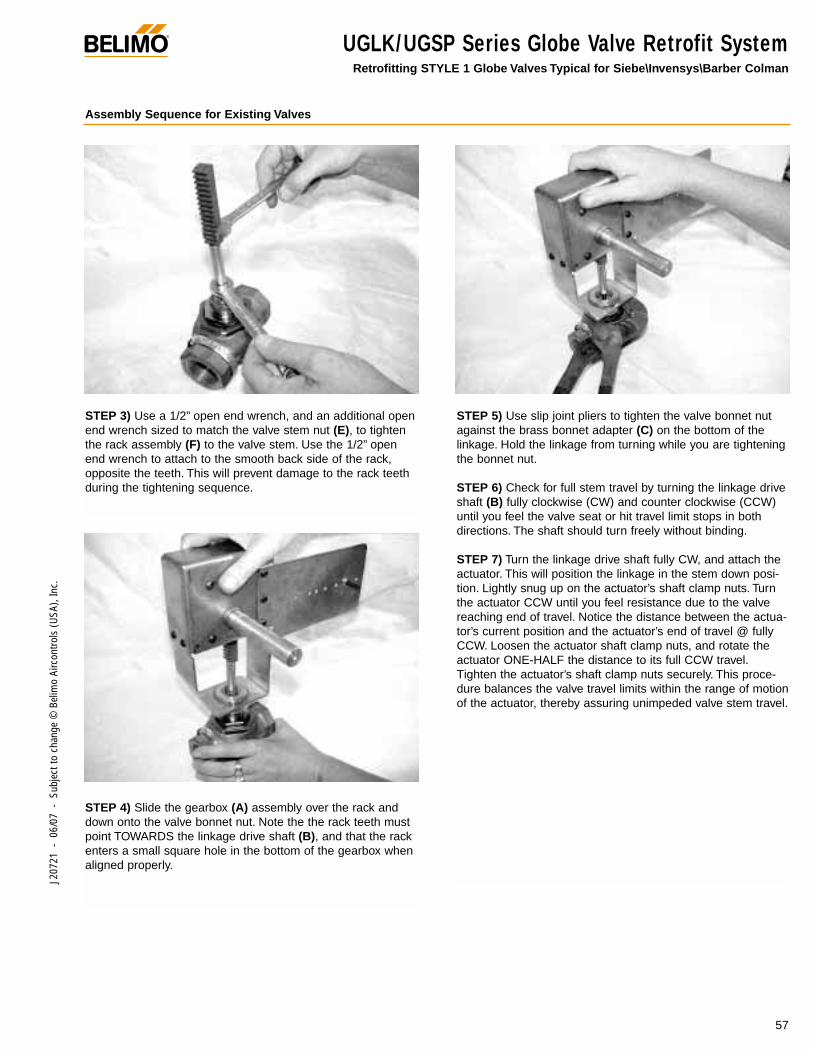
Assembly Sequence for Existing Valves
STEP 3) Use a 1/2” open end wrench, and an additional openend wrench sized to match the valve stem nut (E), to tightenthe rack assembly (F) to the valve stem. Use the 1/2” openend wrench to attach to the smooth back side of the rack,opposite the teeth. This will prevent damage to the rack teethduring the tightening sequence.
STEP 4) Slide the gearbox (A) assembly over the rack anddown onto the valve bonnet nut. Note the the rack teeth mustpoint TOWARDS the linkage drive shaft (B), and that the rackenters a small square hole in the bottom of the gearbox whenaligned properly.
STEP 5) Use slip joint pliers to tighten the valve bonnet nutagainst the brass bonnet adapter (C) on the bottom of thelinkage. Hold the linkage from turning while you are tighteningthe bonnet nut.
STEP 6) Check for full stem travel by turning the linkage driveshaft (B) fully clockwise (CW) and counter clockwise (CCW)until you feel the valve seat or hit travel limit stops in bothdirections. The shaft should turn freely without binding.
STEP 7) Turn the linkage drive shaft fully CW, and attach theactuator. This will position the linkage in the stem down posi-tion. Lightly snug up on the actuator’s shaft clamp nuts. Turnthe actuator CCW until you feel resistance due to the valvereaching end of travel. Notice the distance between the actua-tor’s current position and the actuator’s end of travel @ fullyCCW. Loosen the actuator shaft clamp nuts, and rotate theactuator ONE-HALF the distance to its full CCW travel.Tighten the actuator’s shaft clamp nuts securely. This proce-dure balances the valve travel limits within the range of motionof the actuator, thereby assuring unimpeded valve stem travel.
UGLK/UGSP Series Globe Valve Retrofit SystemRetrofitting STYLE 1 Globe Valves Typical for Siebe\Invensys\Barber Colman
®
57
J207
21 -
06/
07 -
Sub
ject
to c
hang
e ©
Bel
imo
Airc
ontro
ls (U
SA),
Inc.
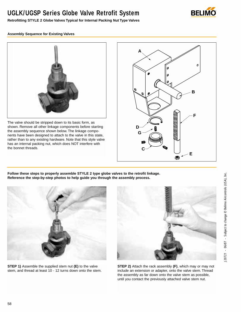
®
58
J207
21 -
06/
07 -
Sub
ject
to c
hang
e ©
Bel
imo
Airc
ontro
ls (U
SA),
Inc.
UGLK/UGSP Series Globe Valve Retrofit SystemRetrofitting STYLE 2 Globe Valves Typical for Internal Packing Nut Type Valves
Assembly Sequence for Existing Valves
Follow these steps to properly assemble STYLE 2 type globe valves to the retrofit linkage.Reference the step-by-step photos to help guide you through the assembly process.
STEP 1) Assemble the supplied stem nut (E) to the valvestem, and thread at least 10 - 12 turns down onto the stem.
STEP 2) Attach the rack assembly (F), which may or may notinclude an extension or adapter, onto the valve stem. Threadthe assembly as far down onto the valve stem as possible,until you contact the previously attached valve stem nut.
The valve should be stripped down to its basic form, asshown. Remove all other linkage components before startingthe assembly sequence shown below. The linkage compo-nents have been designed to attach to the valve in this state,rather than to any existing hardware. Note that this style valvehas an internal packing nut, which does NOT interfere withthe bonnet threads.
A
C
D
F
B
E
G
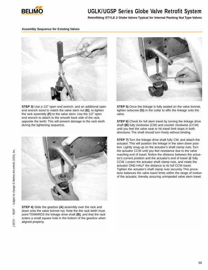
®
59
J207
21 -
06/
07 -
Sub
ject
to c
hang
e ©
Bel
imo
Airc
ontro
ls (U
SA),
Inc.
UGLK/UGSP Series Globe Valve Retrofit SystemRetrofitting STYLE 2 Globe Valves Typical for Internal Packing Nut Type Valves
Assembly Sequence for Existing Valves
STEP 3) Use a 1/2” open end wrench, and an additional openend wrench sized to match the valve stem nut (E), to tightenthe rack assembly (F) to the valve stem. Use the 1/2” openend wrench to attach to the smooth back side of the rack,opposite the teeth. This will prevent damage to the rack teethduring the tightening sequence.
STEP 4) Slide the gearbox (A) assembly over the rack anddown onto the valve bonnet nut. Note the the rack teeth mustpoint TOWARDS the linkage drive shaft (B), and that the rackenters a small square hole in the bottom of the gearbox whenaligned properly.
STEP 5) Once the linkage is fully seated on the valve bonnet,tighten setscrew (G) in the collar to affix the linkage onto thevalve.
STEP 6) Check for full stem travel by turning the linkage driveshaft (B) fully clockwise (CW) and counter clockwise (CCW)until you feel the valve seat or hit travel limit stops in bothdirections. The shaft should turn freely without binding.
STEP 7) Turn the linkage drive shaft fully CW, and attach theactuator. This will position the linkage in the stem down posi-tion. Lightly snug up on the actuator’s shaft clamp nuts. Turnthe actuator CCW until you feel resistance due to the valvereaching end of travel. Notice the distance between the actua-tor’s current position and the actuator’s end of travel @ fullyCCW. Loosen the actuator shaft clamp nuts, and rotate theactuator ONE-HALF the distance to its full CCW travel.Tighten the actuator’s shaft clamp nuts securely. This proce-dure balances the valve travel limits within the range of motionof the actuator, thereby assuring unimpeded valve stem travel.
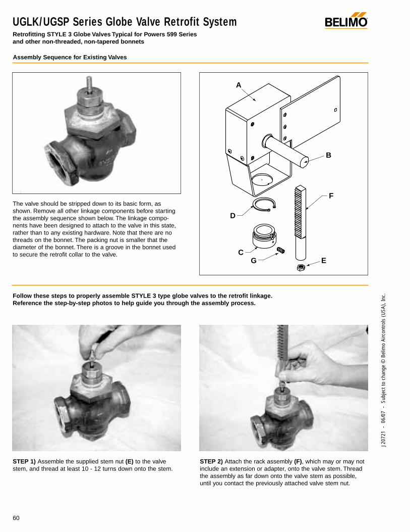
®
60
J207
21 -
06/
07 -
Sub
ject
to c
hang
e ©
Bel
imo
Airc
ontro
ls (U
SA),
Inc.
UGLK/UGSP Series Globe Valve Retrofit SystemRetrofitting STYLE 3 Globe Valves Typical for Powers 599 Series and other non-threaded, non-tapered bonnets
Assembly Sequence for Existing Valves
The valve should be stripped down to its basic form, asshown. Remove all other linkage components before startingthe assembly sequence shown below. The linkage compo-nents have been designed to attach to the valve in this state,rather than to any existing hardware. Note that there are nothreads on the bonnet. The packing nut is smaller that thediameter of the bonnet. There is a groove in the bonnet usedto secure the retrofit collar to the valve.
Follow these steps to properly assemble STYLE 3 type globe valves to the retrofit linkage.Reference the step-by-step photos to help guide you through the assembly process.
A
C
D
F
B
EG
STEP 1) Assemble the supplied stem nut (E) to the valvestem, and thread at least 10 - 12 turns down onto the stem.
STEP 2) Attach the rack assembly (F), which may or may notinclude an extension or adapter, onto the valve stem. Threadthe assembly as far down onto the valve stem as possible,until you contact the previously attached valve stem nut.
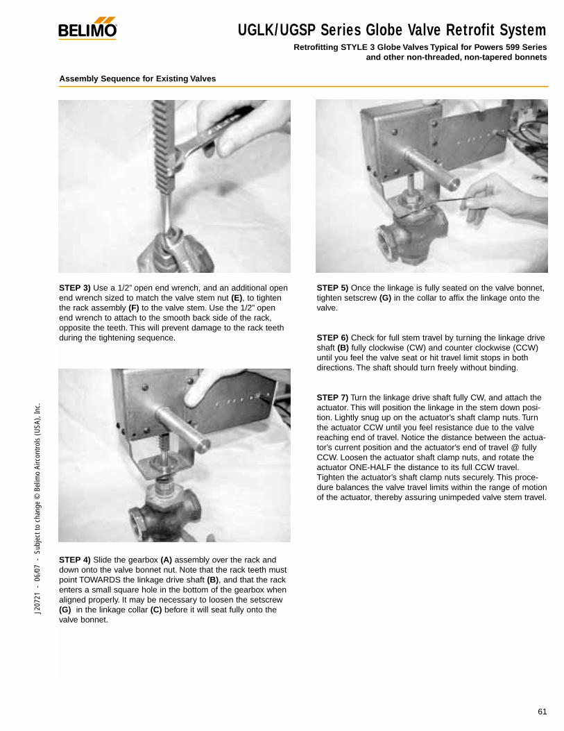
®
61
J207
21 -
06/
07 -
Sub
ject
to c
hang
e ©
Bel
imo
Airc
ontro
ls (U
SA),
Inc.
UGLK/UGSP Series Globe Valve Retrofit SystemRetrofitting STYLE 3 Globe Valves Typical for Powers 599 Series
and other non-threaded, non-tapered bonnets
Assembly Sequence for Existing Valves
STEP 3) Use a 1/2” open end wrench, and an additional openend wrench sized to match the valve stem nut (E), to tightenthe rack assembly (F) to the valve stem. Use the 1/2” openend wrench to attach to the smooth back side of the rack,opposite the teeth. This will prevent damage to the rack teethduring the tightening sequence.
STEP 4) Slide the gearbox (A) assembly over the rack anddown onto the valve bonnet nut. Note that the rack teeth mustpoint TOWARDS the linkage drive shaft (B), and that the rackenters a small square hole in the bottom of the gearbox whenaligned properly. It may be necessary to loosen the setscrew(G) in the linkage collar (C) before it will seat fully onto thevalve bonnet.
STEP 5) Once the linkage is fully seated on the valve bonnet,tighten setscrew (G) in the collar to affix the linkage onto thevalve.
STEP 6) Check for full stem travel by turning the linkage driveshaft (B) fully clockwise (CW) and counter clockwise (CCW)until you feel the valve seat or hit travel limit stops in bothdirections. The shaft should turn freely without binding.
STEP 7) Turn the linkage drive shaft fully CW, and attach theactuator. This will position the linkage in the stem down posi-tion. Lightly snug up on the actuator’s shaft clamp nuts. Turnthe actuator CCW until you feel resistance due to the valvereaching end of travel. Notice the distance between the actua-tor’s current position and the actuator’s end of travel @ fullyCCW. Loosen the actuator shaft clamp nuts, and rotate theactuator ONE-HALF the distance to its full CCW travel.Tighten the actuator’s shaft clamp nuts securely. This proce-dure balances the valve travel limits within the range of motionof the actuator, thereby assuring unimpeded valve stem travel.
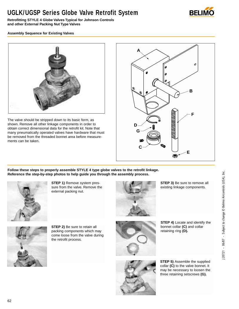
®
62
J207
21 -
06/
07 -
Sub
ject
to c
hang
e ©
Bel
imo
Airc
ontro
ls (U
SA),
Inc.
UGLK/UGSP Series Globe Valve Retrofit SystemRetrofitting STYLE 4 Globe Valves Typical for Johnson Controls and other External Packing Nut Type Valves
Assembly Sequence for Existing Valves
A
C
D
F
B
E
G
Follow these steps to properly assemble STYLE 4 type globe valves to the retrofit linkage.Reference the step-by-step photos to help guide you through the assembly process.
The valve should be stripped down to its basic form, asshown. Remove all other linkage components in order toobtain correct dimensional data for the retrofit kit. Note thatmany pneumatically operated valves have hardware that mustbe removed from the threaded bonnet area before measure-ments can be taken.
STEP 1) Remove system pres-sure from the valve. Remove theexternal packing nut.
STEP 2) Be sure to retain allpacking components which maycome loose from the valve duringthe retrofit process.
STEP 3) Be sure to remove allexisting linkage components.
STEP 4) Locate and identify thebonnet collar (C) and collarretaining ring (D).
STEP 5) Assemble the suppliedcollar (C) to the valve bonnet. Itmay be necessary to loosen thethree retaining setscrews (G).
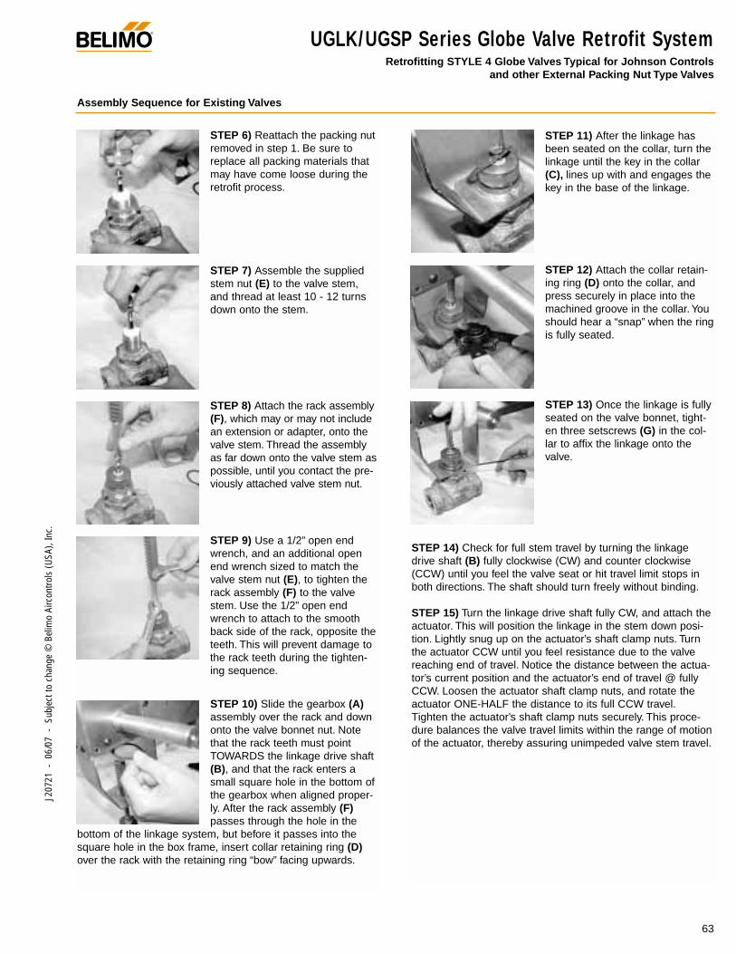
STEP 11) After the linkage hasbeen seated on the collar, turn thelinkage until the key in the collar(C), lines up with and engages thekey in the base of the linkage.
STEP 12) Attach the collar retain-ing ring (D) onto the collar, andpress securely in place into themachined groove in the collar. Youshould hear a “snap” when the ringis fully seated.
STEP 13) Once the linkage is fullyseated on the valve bonnet, tight-en three setscrews (G) in the col-lar to affix the linkage onto thevalve.
STEP 14) Check for full stem travel by turning the linkagedrive shaft (B) fully clockwise (CW) and counter clockwise(CCW) until you feel the valve seat or hit travel limit stops inboth directions. The shaft should turn freely without binding.
STEP 15) Turn the linkage drive shaft fully CW, and attach theactuator. This will position the linkage in the stem down posi-tion. Lightly snug up on the actuator’s shaft clamp nuts. Turnthe actuator CCW until you feel resistance due to the valvereaching end of travel. Notice the distance between the actua-tor’s current position and the actuator’s end of travel @ fullyCCW. Loosen the actuator shaft clamp nuts, and rotate theactuator ONE-HALF the distance to its full CCW travel.Tighten the actuator’s shaft clamp nuts securely. This proce-dure balances the valve travel limits within the range of motionof the actuator, thereby assuring unimpeded valve stem travel.
®
63
J207
21 -
06/
07 -
Sub
ject
to c
hang
e ©
Bel
imo
Airc
ontro
ls (U
SA),
Inc.
Assembly Sequence for Existing Valves
UGLK/UGSP Series Globe Valve Retrofit SystemRetrofitting STYLE 4 Globe Valves Typical for Johnson Controls
and other External Packing Nut Type Valves
STEP 6) Reattach the packing nutremoved in step 1. Be sure toreplace all packing materials thatmay have come loose during theretrofit process.
STEP 7) Assemble the suppliedstem nut (E) to the valve stem,and thread at least 10 - 12 turnsdown onto the stem.
STEP 8) Attach the rack assembly(F), which may or may not includean extension or adapter, onto thevalve stem. Thread the assemblyas far down onto the valve stem aspossible, until you contact the pre-viously attached valve stem nut.
STEP 9) Use a 1/2” open endwrench, and an additional openend wrench sized to match thevalve stem nut (E), to tighten therack assembly (F) to the valvestem. Use the 1/2” open endwrench to attach to the smoothback side of the rack, opposite theteeth. This will prevent damage tothe rack teeth during the tighten-ing sequence.
STEP 10) Slide the gearbox (A)assembly over the rack and downonto the valve bonnet nut. Notethat the rack teeth must pointTOWARDS the linkage drive shaft(B), and that the rack enters asmall square hole in the bottom ofthe gearbox when aligned proper-ly. After the rack assembly (F)passes through the hole in the
bottom of the linkage system, but before it passes into thesquare hole in the box frame, insert collar retaining ring (D)over the rack with the retaining ring “bow” facing upwards.
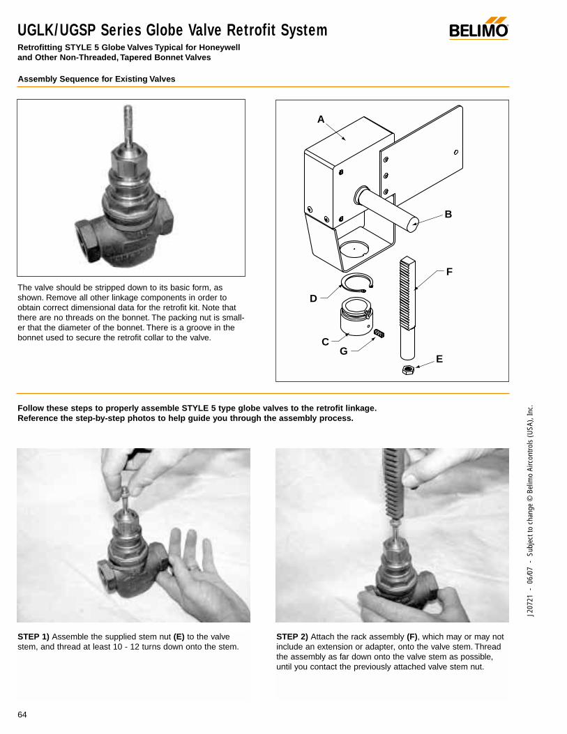
®
64
J207
21 -
06/
07 -
Sub
ject
to c
hang
e ©
Bel
imo
Airc
ontro
ls (U
SA),
Inc.
UGLK/UGSP Series Globe Valve Retrofit SystemRetrofitting STYLE 5 Globe Valves Typical for Honeywell and Other Non-Threaded, Tapered Bonnet Valves
Assembly Sequence for Existing Valves
The valve should be stripped down to its basic form, asshown. Remove all other linkage components in order toobtain correct dimensional data for the retrofit kit. Note thatthere are no threads on the bonnet. The packing nut is small-er that the diameter of the bonnet. There is a groove in thebonnet used to secure the retrofit collar to the valve.
Follow these steps to properly assemble STYLE 5 type globe valves to the retrofit linkage.Reference the step-by-step photos to help guide you through the assembly process.
A
C
D
F
B
EG
STEP 1) Assemble the supplied stem nut (E) to the valvestem, and thread at least 10 - 12 turns down onto the stem.
STEP 2) Attach the rack assembly (F), which may or may notinclude an extension or adapter, onto the valve stem. Threadthe assembly as far down onto the valve stem as possible,until you contact the previously attached valve stem nut.
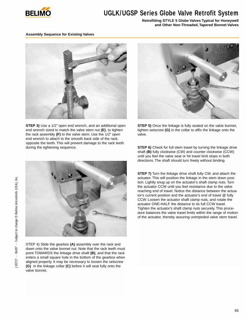
UGLK/UGSP Series Globe Valve Retrofit SystemRetrofitting STYLE 5 Globe Valves Typical for Honeywell
and Other Non-Threaded, Tapered Bonnet Valves
®
65
J207
21 -
06/
07 -
Sub
ject
to c
hang
e ©
Bel
imo
Airc
ontro
ls (U
SA),
Inc.
Assembly Sequence for Existing Valves
STEP 3) Use a 1/2” open end wrench, and an additional openend wrench sized to match the valve stem nut (E), to tightenthe rack assembly (F) to the valve stem. Use the 1/2” openend wrench to attach to the smooth back side of the rack,opposite the teeth. This will prevent damage to the rack teethduring the tightening sequence.
STEP 4) Slide the gearbox (A) assembly over the rack anddown onto the valve bonnet nut. Note that the rack teeth mustpoint TOWARDS the linkage drive shaft (B), and that the rackenters a small square hole in the bottom of the gearbox whenaligned properly. It may be necessary to loosen the setscrew(G) in the linkage collar (C) before it will seat fully onto thevalve bonnet.
STEP 5) Once the linkage is fully seated on the valve bonnet,tighten setscrew (G) in the collar to affix the linkage onto thevalve.
STEP 6) Check for full stem travel by turning the linkage driveshaft (B) fully clockwise (CW) and counter clockwise (CCW)until you feel the valve seat or hit travel limit stops in bothdirections. The shaft should turn freely without binding.
STEP 7) Turn the linkage drive shaft fully CW, and attach theactuator. This will position the linkage in the stem down posi-tion. Lightly snug up on the actuator’s shaft clamp nuts. Turnthe actuator CCW until you feel resistance due to the valvereaching end of travel. Notice the distance between the actua-tor’s current position and the actuator’s end of travel @ fullyCCW. Loosen the actuator shaft clamp nuts, and rotate theactuator ONE-HALF the distance to its full CCW travel.Tighten the actuator’s shaft clamp nuts securely. This proce-dure balances the valve travel limits within the range of motionof the actuator, thereby assuring unimpeded valve stem travel.

Notes/Work Pad®
66
J207
21 -
06/
07 -
Sub
ject
to c
hang
e ©
Bel
imo
Airc
ontro
ls (U
SA),
Inc.

J207
21 -
06/
07 -
Sub
ject
to c
hang
e ©
Bel
imo
Airc
ontro
ls (U
SA),
Inc.
®
To g e t h e r t o t h e To p
Midwest Service Center(877) 833-1647
Canada Locations
14/16 – 5716 Coopers Ave. Quebec & Eastern CanadaMississauga, Ontario Service CenterL4Z 2E8 (866) 928-1440Toll Free: (866) 805-7089 (450) 928-1440(905) 712-3118 Fax: (450) 928-0050Fax: (905) 712-3124
(USA) Locations / 1-800-543-9038
43 Old Ridgebury Road 1675 East Prater WayDanbury, CT 06810 Suite 101Toll Free: (800) 543-9038 Sparks, NV 89434(203) 791-9915 Toll Free: (800) 987-9042Fax: (800) 228-8283 (775) 857-4243
(800-ACTUATE) Fax: (800) 987-8875(203) 791-9919 (775) 857-4255
South Customer Service:888-829-3166Fax: 800-228-8283
Mid-West Customer Service:877-833-1647Fax: 800-228-8283
Latin America Customer Service:203-791-8396Fax: 203-791-9139
Belimo Worldwide
Belimo Americas servescustomers throughout theUnited States, Canada, and Latin America.
It is part of Belimo Holding,a publicly held company inSwitzerland with businessunits in the Americas,Europe, and Asia Pacific.
Belimo Americas
www.belimo.com