Embed Size (px)
Citation preview
2012/10 – Subject to change – FAST Program Catalog 137� Internet: www.festo.com/catalog/...
Valve Manifolds Type 44 VTSA, Type 45 VTSA-F – Metric SeriesOverview
� Modular multi-functional valve manifold for up to 32 valves:
– Type 44 VTSA, ISO 15407-2/ISO 5599-2
– Type 45 VTSA-F with optimized flow
� Different valve sizes on one valve manifold:
– 18 mm (ISO 02)
– 26 mm (ISO 01)
– 42 mm (IS0 1), type 44 VTSA only
– 52 mm (IS0 2), type 44 VTSA only
� Flow rate: up to 2,900 l/min
� Pneumatic connections with threaded connector or QS fitting
� Design suitable for electrical peripherals CPX
Product Range Overview
Electrical connection Valve types
5/2
-way
val
ve, s
ingl
e so
leno
id
wit
h pn
eum
atic
spr
ing
retu
rn
5/2
-way
val
ve, s
ingl
e so
leno
id
wit
h sp
ring
retu
rn
5/2
-way
val
ve, d
oubl
e
sole
noid
5/2
-way
val
ve, d
oubl
e so
leno
id
dom
inan
t sw
itch
ing
2x
3/2
-way
val
ve,
norm
ally
ope
n
2x
3/2
-way
val
ve,
norm
ally
clo
sed
2x
3/2
-way
val
ve: 1
x no
rmal
ly
open
, 1x
norm
ally
clo
sed
5/3
-way
val
ve,
mid
-pos
itio
n pr
essu
rize
d
5/3
-way
val
ve,
mid
-pos
itio
n cl
osed
5/3
-way
val
ve,
mid
-pos
itio
n ex
haus
ted
2x
3/2
-way
val
ve, n
orm
ally
open
, rev
erse
ope
rati
on
2x
3/2
-way
val
ve, n
orm
ally
clos
ed, r
ever
se o
pera
tion
2x
3/2
-way
val
ve:
1x
norm
ally
ope
n, 1
x no
rmal
ly
clos
ed, r
ever
se o
pera
tion
Bla
nkin
g pl
ate
for
vaca
nt
posi
tion
M O J D N K H B G E P Q R L
Electrical multi-pin plug connection,
CageClamp� � � � � � � � � � � � � �
Electrical multi-pin plug connection,
Sub-D (37-pin)� � � � � � � � � � � � � �
Fieldbus connection/control block� � � � � � � � � � � � � �
Key features
Multi-pin plug manifold Fieldbus manifold/control block Comprehensive Combinable
� Max. 32 valve positions/
max. 32 solenoid coils
� Parallel modular valve linking via
circuit boards
� Any compressed-air supply
� Any number of pressure zones
� Max. 32 valve positions/
max. 32 solenoid coils
� Any compressed-air supply
� Any number of pressure zones
� 18 mm (ISO Size 02): Valve flow rate
up to 550 l/min
� 26 mm (ISO Size 01): Valve flow rate
up to 1,100 l/min
� 42 mm (ISO Size 1):
valve flow rate up to 1,500 l/min
� 52 mm (ISO Size 2):
valve flow rate up to 2,900 l/min
� Width 18 mm (Size 02), 26 mm
(Size 01), 42 mm (Size 1) and 52 mm
(Size 2) can be combined on a single
valve manifold
Contents
– Options Overview � 138
– Technical Data � 140
– Ordering Data � 143
– Accessories Overview � 144
Valv
es a
nd V
alve
Man
ifol
ds
2
Detailed product information � www.festo.com/catalog/vtsa
Note: All metric products can be used within inch tubing systems via hybrid fittings (� Overview on page 241)
FAST Program Catalog – Subject to change – 2012/10138 � Internet: www.festo.com/catalog/...
Valve Manifolds Type 44 VTSA, Type 45 VTSA-F – Metric SeriesOverview
Flexible Easily integrated Comprehensive Installation and maintenance
� Easy modification and expansion due
to high degree of modularity. Fast
connection of the subbases by means
of four screws.
� Fully modular system allows the
combination of 18 mm (Size 02),
26 mm (Size 01), 42 mm (Size 1) and
52 mm (Size 2) valves on the same
manifold without the need for any
transition/adapter plate.
� Change direction of working ports
with easy-to-install angle plate.
� Fieldbus valve manifold suitable for
CPX electrical peripherals.
� Fieldbus nodes: Interbus, DeviceNet,
Profibus DP, CANopen, CC-Link via
CPX terminal
� Ethernet: Modbus/TCP, EtherNet/IP,
TCP/IP via CPX terminal
� Full complement of CPX I/O modules
� Expandable up to 32 solenoid coils
� Integration of a wide range of function
modules possible
� Supply plates permit a flexible air
supply and variable pressure zones
� High-performance valves in a sturdy
metal housing
� Complete range of vertical sandwich
components such as pressure
regulators, flow control valve,
individual pressure supply, shutoff
plate (hot swap).
� Standard air qualities: 40 micron
filtration grade. Can be used with
lubricated or non-lubricated air, and
inert gases.
� Manual override available, with
momentary, locking, or hidden
(non-accessible) options.
� Ready-to-install unit, preassembled
and tested
� Durable, low cost identification by
label holder on the valve or label
holder on the subbase.
� Secure wall mounting or DIN rail
mounting
� Fast troubleshooting thanks to LEDs
on the valves and diagnosis via
fieldbus.
� Reliability of service thanks to valves
that can be replaced easily and
quickly.
� Easy fault identification using
CPX-MMI handheld diagnostic unit.
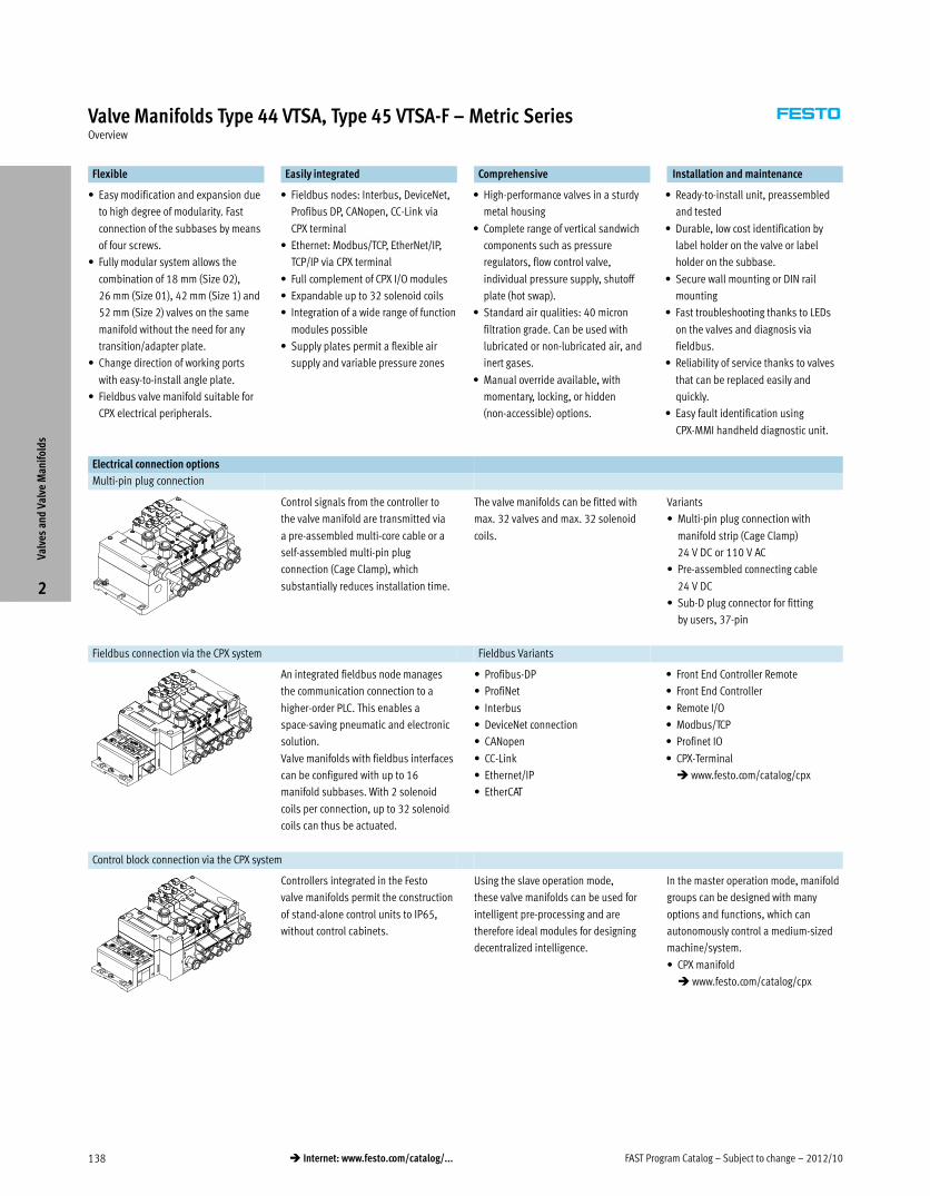
Electrical connection options
Multi-pin plug connection
Control signals from the controller to
the valve manifold are transmitted via
a pre-assembled multi-core cable or a
self-assembled multi-pin plug
connection (Cage Clamp), which
substantially reduces installation time.
The valve manifolds can be fitted with
max. 32 valves and max. 32 solenoid
coils.
Variants
� Multi-pin plug connection with
manifold strip (Cage Clamp)
24 V DC or 110 V AC
� Pre-assembled connecting cable
24 V DC
� Sub-D plug connector for fitting
by users, 37-pin
Fieldbus connection via the CPX system Fieldbus Variants
An integrated fieldbus node manages
the communication connection to a
higher-order PLC. This enables a
space-saving pneumatic and electronic
solution.
Valve manifolds with fieldbus interfaces
can be configured with up to 16
manifold subbases. With 2 solenoid
coils per connection, up to 32 solenoid
coils can thus be actuated.
� Profibus-DP
� ProfiNet
� Interbus
� DeviceNet connection
� CANopen
� CC-Link
� Ethernet/IP
� EtherCAT
� Front End Controller Remote
� Front End Controller
� Remote I/O
� Modbus/TCP
� Profinet IO
� CPX-Terminal
� www.festo.com/catalog/cpx
Control block connection via the CPX system
Controllers integrated in the Festo
valve manifolds permit the construction
of stand-alone control units to IP65,
without control cabinets.
Using the slave operation mode,
these valve manifolds can be used for
intelligent pre-processing and are
therefore ideal modules for designing
decentralized intelligence.
In the master operation mode, manifold
groups can be designed with many
options and functions, which can
autonomously control a medium-sized
machine/system.
� CPX manifold
� www.festo.com/catalog/cpx
Valv
es a
nd V
alve
Man
ifol
ds
2
2012/10 – Subject to change – FAST Program Catalog 139� Internet: www.festo.com/catalog/...
Valve Manifolds Type 44 VTSA, Type 45 VTSA-F – Metric SeriesOverview
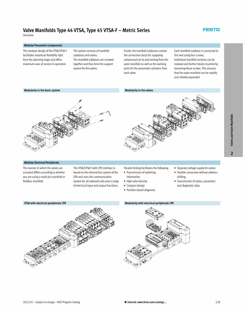
Modular Pneumatic Components
The modular design of the VTSA/VTSA-F
facilitates maximum flexibility right
from the planning stage and offers
maximum ease of service in operation.
The system consists of manifold
subbases and valves.
The manifold subbases are screwed
together and thus form the support
system for the valves.
Inside, the manifold subbases contain
the connection ducts for supplying
compressed air to and venting from the
valve manifold as well as the working
ports for the pneumatic cylinders from
each valve.
Each manifold subbase is connected to
the next using four screws.
Individual manifold sections can be
isolated and further blocks inserted by
loosening these screws. This ensures
that the valve manifold can be rapidly
and reliably expanded.
Modularity in the basic system Modularity in the valves
Modular Electrical Peripherals
The manner in which the valves are
actuated differs according to whether
you are using a multi-pin manifold or
fieldbus manifold.
The VTSA/VTSA-F with CPX interface is
based on the internal bus system of the
CPX and uses this communication
system for all solenoid coils and a range
of electrical input and output functions.
Parallel linking facilitates the following:
� Transmission of switching
information
� High valve density
� Compact design
� Position-based diagnosis
� Separate voltage supply for valves
� Flexible conversion without address
shifting
� Transmission of status, parameter
and diagnostic data
VTSA with electrical peripherals CPX Modularity with electrical peripherals CPX
Valv
es a
nd V
alve
Man
ifol
ds
2
FAST Program Catalog – Subject to change – 2012/10140 � Internet: www.festo.com/catalog/...
Valve Manifolds Type 44 VTSA, Type 45 VTSA-F – Metric SeriesTechnical Data
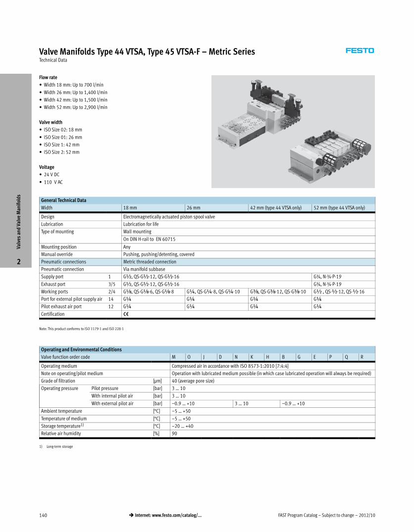
Flow rate
� Width 18 mm: Up to 700 l/min
� Width 26 mm: Up to 1,400 l/min
� Width 42 mm: Up to 1,500 l/min
� Width 52 mm: Up to 2,900 l/min
Valve width
� ISO Size 02: 18 mm
� ISO Size 01: 26 mm
� ISO Size 1: 42 mm
� ISO Size 2: 52 mm
Voltage
� 24 V DC
� 110 V AC
General Technical Data
Width 18 mm 26 mm 42 mm (type 44 VTSA only) 52 mm (type 44 VTSA only)
Design Electromagnetically actuated piston spool valve
Lubrication Lubrication for life
Type of mounting Wall mounting
On DIN H-rail to EN 60715
Mounting position Any
Manual override Pushing, pushing/detenting, covered
Pneumatic connections Metric threaded connection
Pneumatic connection Via manifold subbase
Supply port 1 G½, QS-G½-12, QS-G½-16 G¾, N-¾-P-19
Exhaust port 3/5 G½, QS-G½-12, QS-G½-16 G¾, N-¾-P-19
Working ports 2/4 Gx, QS-Gx-6, QS-Gx-8 G¼, QS-G¼-8, QS-G¼-10 Gy, QS-Gy-12, QS-Gy-10 G½ , QS-½-12, QS-½-16
Port for external pilot supply air 14 G¼ G¼ G¼ G¼
Pilot exhaust air port 12 G¼ G¼ G¼ G¼
Certification —
Note: This product conforms to ISO 1179-1 and ISO 228-1
Operating and Environmental Conditions
Valve function order code M O J D N K H B G E P Q R
Operating medium Compressed air in accordance with ISO 8573-1:2010 [7:4:4]
Note on operating/pilot medium Operation with lubricated medium possible (in which case lubricated operation will always be required)
Grade of filtration [μm] 40 (average pore size)
Operating pressure Pilot pressure [bar] 3 … 10
With internal pilot air [bar] 3 … 10
With external pilot air [bar] –0.9 … +10 3 … 10 –0.9 … +10
Ambient temperature [°C] –5 … +50
Temperature of medium [°C] –5 … +50
Storage temperature1) [°C] –20 … +40
Relative air humidity [%] 90
1) Long-term storage
Valv
es a
nd V
alve
Man
ifol
ds
2
2012/10 – Subject to change – FAST Program Catalog 141� Internet: www.festo.com/catalog/...
Valve Manifolds Type 44 VTSA, Type 45 VTSA-F – Metric SeriesTechnical Data
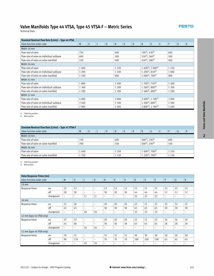
Standard Nominal Flow Rate [l/min] – Type 44 VTSA
Valve function order code M O J D N K H B G E P Q R
Width 18 mm
Flow rate of valve 750 600 7001), 4302) 600
Flow rate of valve on individual subbase 600 500 5501), 3602) 500
Flow rate of valve on valve manifold 550 400 4501), 3002) 400
Width 26 mm
Flow rate of valve 1 400 1 250 1 4001), 1 0002) 1 250
Flow rate of valve on individual subbase 1 200 1 100 1 2001), 8502) 1 000
Flow rate of valve on valve manifold 1 100 900 1 0001), 7002) 900
Width 42 mm
Flow rate of valve 1 800 1 400 1 7001), 7502) 1 400
Flow rate of valve on individual subbase 1 300 1 200 1 2001), 8002) 1 200
Flow rate of valve on valve manifold 1 500 1 200 1 4001), 8002) 1 200
Width 52 mm
Flow rate of valve 4 000 3 000 3 6001), 1 7002) 3 000
Flow rate of valve on individual subbase 3 200 2 500 1 2001), 8002) 2 500
Flow rate of valve on valve manifold 2 900 2 400 2 8001), 1 7002) 2 400
1) Switching position
2) Mid-position
Standard Nominal Flow Rate [l/min] – Type 45 VTSA-F
Valve function order code M O J D N K H B G E P Q R
Width 18 mm
Flow rate of valve 750 600 5001), 3302) 600
Flow rate of valve on valve manifold 700 550 5001), 3302) 550
Width 26 mm
Flow rate of valve 1 400 1 250 1 4001), 7002) 1 250
Flow rate of valve on valve manifold 1 350 1 150 1 3501), 7002) 1 150
1) Switching position
2) Mid-position
Valve Response Times [ms]
Valve function order code M O J D N K H B G E P Q R
18 mm
Response times on 22 12 – – 12 12 12 15 15 15 25 25 25
off 28 38 – – 30 30 30 44 44 44 12 12 12
changeover – – 11 11 – – – 22 22 22 – – –
26 mm
Response times on 25 20 – – 20 20 20 22 22 22 32 32 32
off 45 65 – – 38 38 38 65 65 65 30 30 30
changeover – – 18 18 – – – 33 33 33 – – –
42 mm (type 44 VTSA only)
Response times on 27 22 – – 20 20 20 22 22 22 34 34 34
off 45 60 – – 38 38 38 65 65 65 28 28 28
changeover – – 16 16 – – – – – – – – –
52 mm (type 44 VTSA only)
Response times on 70 25 – – 35 35 35 30 30 30 50 50 50
off 90 110 – – 70 70 70 100 100 100 65 65 65
changeover – – 18 18 – – – – – – – – –
Valv
es a
nd V
alve
Man
ifol
ds
2
FAST Program Catalog – Subject to change – 2012/10142 � Internet: www.festo.com/catalog/...
Valve Manifolds Type 44 VTSA, Type 45 VTSA-F – Metric SeriesTechnical Data
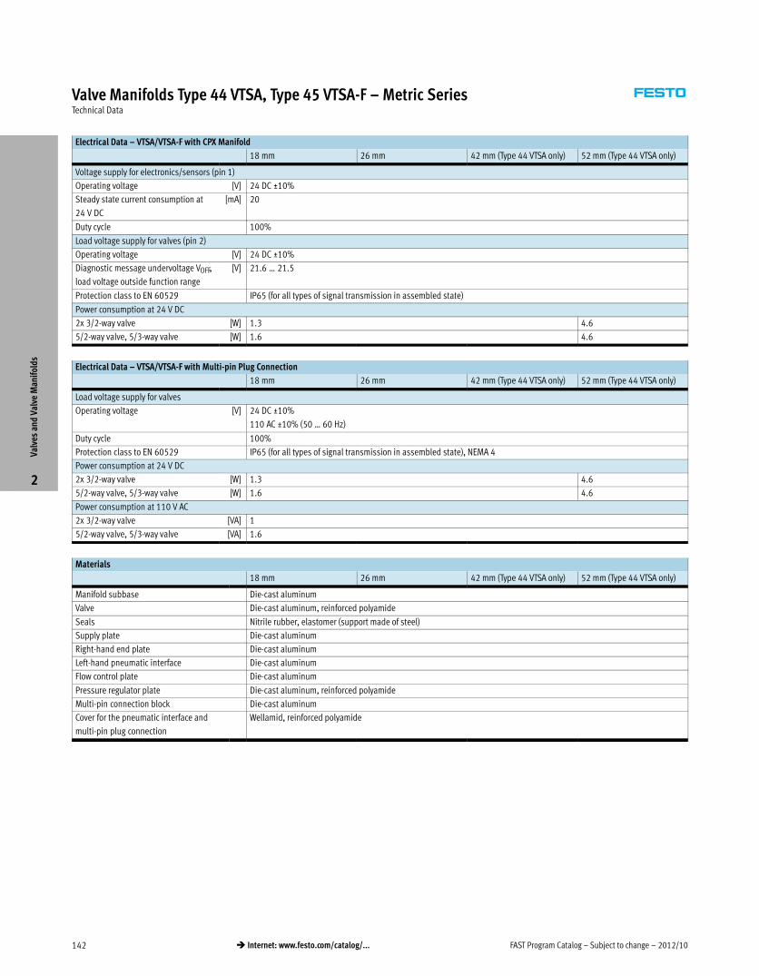
Electrical Data – VTSA/VTSA-F with CPX Manifold
18 mm 26 mm 42 mm (Type 44 VTSA only) 52 mm (Type 44 VTSA only)
Voltage supply for electronics/sensors (pin 1)
Operating voltage [V] 24 DC ±10%
Steady state current consumption at
24 V DC
[mA] 20
Duty cycle 100%
Load voltage supply for valves (pin 2)
Operating voltage [V] 24 DC ±10%
Diagnostic message undervoltage VOFF,
load voltage outside function range
[V] 21.6 … 21.5
Protection class to EN 60529 IP65 (for all types of signal transmission in assembled state)
Power consumption at 24 V DC
2x 3/2-way valve [W] 1.3 4.6
5/2-way valve, 5/3-way valve [W] 1.6 4.6
Electrical Data – VTSA/VTSA-F with Multi-pin Plug Connection
18 mm 26 mm 42 mm (Type 44 VTSA only) 52 mm (Type 44 VTSA only)
Load voltage supply for valves
Operating voltage [V] 24 DC ±10%
110 AC ±10% (50 … 60 Hz)
Duty cycle 100%
Protection class to EN 60529 IP65 (for all types of signal transmission in assembled state), NEMA 4
Power consumption at 24 V DC
2x 3/2-way valve [W] 1.3 4.6
5/2-way valve, 5/3-way valve [W] 1.6 4.6
Power consumption at 110 V AC
2x 3/2-way valve [VA] 1
5/2-way valve, 5/3-way valve [VA] 1.6
Materials
18 mm 26 mm 42 mm (Type 44 VTSA only) 52 mm (Type 44 VTSA only)
Manifold subbase Die-cast aluminum
Valve Die-cast aluminum, reinforced polyamide
Seals Nitrile rubber, elastomer (support made of steel)
Supply plate Die-cast aluminum
Right-hand end plate Die-cast aluminum
Left-hand pneumatic interface Die-cast aluminum
Flow control plate Die-cast aluminum
Pressure regulator plate Die-cast aluminum, reinforced polyamide
Multi-pin connection block Die-cast aluminum
Cover for the pneumatic interface and
multi-pin plug connection
Wellamid, reinforced polyamide
Valv
es a
nd V
alve
Man
ifol
ds
2

2012/10 – Subject to change – FAST Program Catalog 143� Internet: www.festo.com/catalog/...
Valve Manifolds Type 44 VTSA, Type 45 VTSA-F – Metric SeriesOrdering Data
Valve manifold configurator
A valve manifold configurator is
available to help you select a suitable
VTSA/VTSA-F valve manifold. This makes
it much easier for you to find the right
product.
The valve manifolds are fully assembled
according to your order specifications
and are individually tested. This reduces
the amount of assembly and installation
to a minimum.
You order a valve terminal type 44/45
using the order code.
Ordering system for type 44/45
� Internet: type 44, type 45
Ordering system, CPX
� Internet: cpx
The illustration above provides an
example of a valve terminal
configuration.
The following steps explain how you
arrive at the order code:
Once you have called up
www.festo.com/us, click on “Products”
tab and then select the “Catalog” tab on
the left hand side of the “Products”
page.
Now select “Valve Manifolds” and then
“Industry Standard Valve Manifolds”.
Select your desired valve terminal (in
this case VTSA) and then finally click on
link of the product with the desired
actuation methodology.
You can then configure the valve
terminal step by step (from left to right)
according to your requirements. Now
click on the “Add to basket” option to
save the selected configuration (this will
not trigger an order).
2D/3D CAD Data
You can request the CAD data for a valve
terminal you have configured by
selecting the “2D/3D view” option
under the “Add to basket option” in the
valve terminal configurator. You can
generate a 3D preview or request an
email or download of a CAD model in
the format of your choice.Va
lves
and
Val
ve M
anif
olds
2
Lead Time LT for all configurable options on this page: 3D typically ships within 3 days
FAST Program Catalog – Subject to change – 2012/10144 � Internet: www.festo.com/catalog/...
Valve Manifolds Type 44 VTSA, Type 45 VTSA-FAccessories
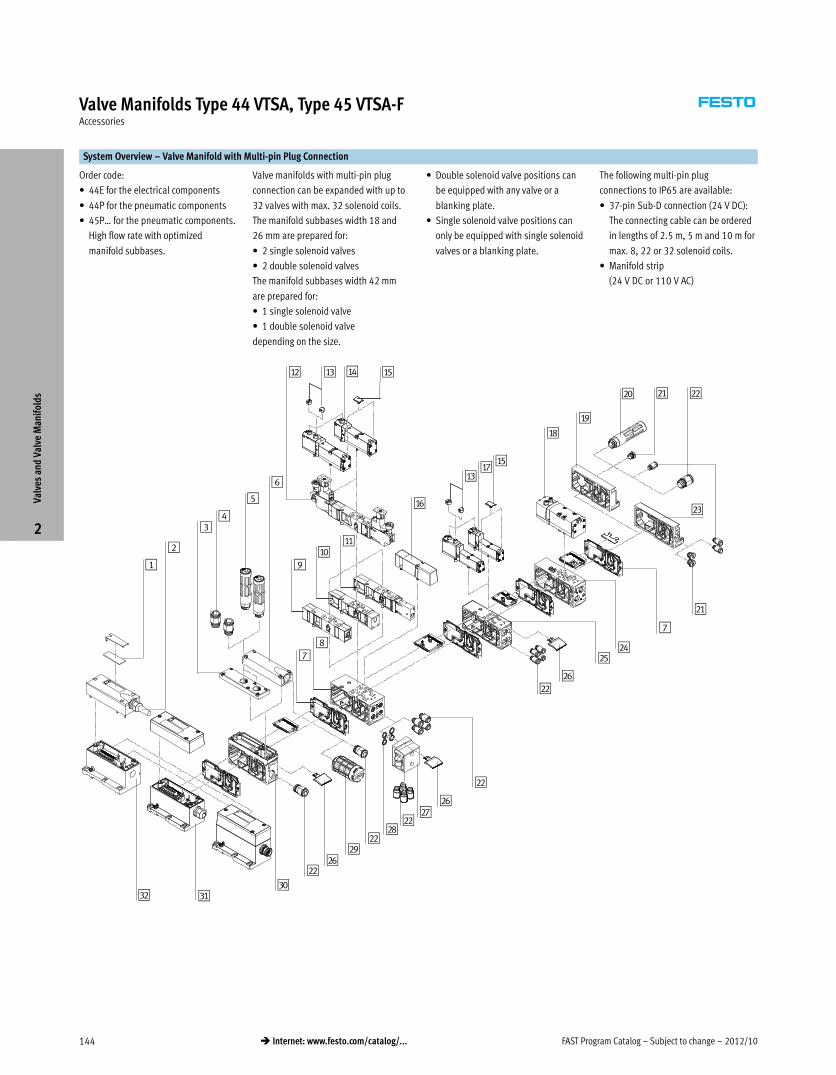
System Overview – Valve Manifold with Multi-pin Plug Connection
Order code:
� 44E for the electrical components
� 44P for the pneumatic components
� 45P… for the pneumatic components.
High flow rate with optimized
manifold subbases.
Valve manifolds with multi-pin plug
connection can be expanded with up to
32 valves with max. 32 solenoid coils.
The manifold subbases width 18 and
26 mm are prepared for:
� 2 single solenoid valves
� 2 double solenoid valves
The manifold subbases width 42 mm
are prepared for:
� 1 single solenoid valve
� 1 double solenoid valve
depending on the size.
� Double solenoid valve positions can
be equipped with any valve or a
blanking plate.
� Single solenoid valve positions can
only be equipped with single solenoid
valves or a blanking plate.
The following multi-pin plug
connections to IP65 are available:
� 37-pin Sub-D connection (24 V DC):
The connecting cable can be ordered
in lengths of 2.5 m, 5 m and 10 m for
max. 8, 22 or 32 solenoid coils.
� Manifold strip
(24 V DC or 110 V AC)
2
1
aC
34
5
6
aB aEaD
78
9aJ
aA
aF
aCaG
aE
aH
aI
bJ bA bB
bC
bA
7
bD
bF
bE
bB
bB
bF
bB
bG
bHbB
bFbB
bI
cJcAcB
Valv
es a
nd V
alve
Man
ifol
ds
2

2012/10 – Subject to change – FAST Program Catalog 145� Internet: www.festo.com/catalog/...
Valve Manifolds Type 44 VTSA, Type 45 VTSA-FAccessories
System Overview – Valve Manifold with Multi-pin Plug Connection
Brief description
1 Inscription labels Large, for multi-pin plug connection
2 Multi-core cable –
3 Exhaust plate Ports 3 and 5 separated
4 Fittings For supply plate
5 Silencer For supply plate
6 Exhaust port cover For ducted exhaust air (ports 3 and 5
combined)
7 Duct separation/seal –
8 Manifold subbase For valves with a width of 26 mm
9 Flow control plate –
aJ Vertical supply plate –
aA Vertical shut-off plate –
aB Pressure regulator plate –
aC Cover cap For manual override, pushing, covered
aD Valve Width 26 mm
aE Inscription label holder For valve
aF Blanking plate For unused valve position (vacant position)
aG Valve Width 18 mm
Brief description
aH Valve Width 42 mm (type 44 only)
aI Right-hand end plate –
bJ Silencer For end plate
bA Blanking plugs –
bB Fittings –
bC End plate with pilot air selector –
bD Manifold subbase For valves with a width of 42 mm (type 44
only)
bE Manifold subbase For valves with a width of 18 mm
bF Inscription label holder For supply plate, subbase, 90°
connection plate
bG 90° connection plate –
bH Seals –
bI Silencer –
cJ Supply plate –
cA Multi-pin plug connection Via manifold strip (CageClamp) 24 V DC or110 V AC
cB Multi-pin plug connection With multi-core cable 24 V DC
Valv
es a
nd V
alve
Man
ifol
ds
2

FAST Program Catalog – Subject to change – 2012/10146 � Internet: www.festo.com/catalog/...
Valve Manifolds Type 44 VTSA, Type 45 VTSA-FSystem Overview
System Overview – Valve Manifold with Fieldbus Connection, Control Block (Electrical Peripherals CPX)
Order code:
� 50E-… for the electrical peripherals
� 44P for the pneumatic components
� 45P… for the pneumatic components.
High flow rate with optimized
manifold subbases.
Valve manifolds with fieldbus interface
can be expanded with up to 32 valves
with max. 32 solenoid coils.
Each valve position can be fitted with
any valve or a blanking plate.
The rules for CPX apply to the
equipment that can be used in
combination with the electrical
peripherals CPX.
In general:
� Max. 10 electrical modules
� Digital inputs/outputs
� Analog inputs/outputs
� Parameterisation of inputs and
outputs
� Integrated feature-rich diagnostic
system
� Preventive maintenance concepts
1
aB
23
4
5
aA aDaC
67
89
aJ
aE
aBaF
aD
aG
aH
aI bJ bA
bB
bJ
6
bC
bE
bD
bA
bA
bE
bA
bF
bGbA
bFbA
bH
bI6cJcA
Valv
es a
nd V
alve
Man
ifol
ds
2
2012/10 – Subject to change – FAST Program Catalog 147� Internet: www.festo.com/catalog/...
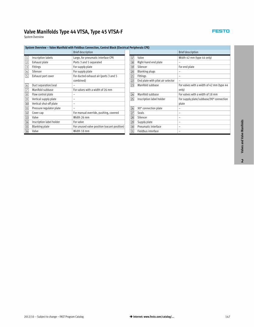
Valve Manifolds Type 44 VTSA, Type 45 VTSA-FSystem Overview
System Overview – Valve Manifold with Fieldbus Connection, Control Block (Electrical Peripherals CPX)
Brief description
1 Inscription labels Large, for pneumatic interface CPX
2 Exhaust plate Ports 3 and 5 separated
3 Fittings For supply plate
4 Silencer For supply plate
5 Exhaust port cover For ducted exhaust air (ports 3 and 5
combined)
6 Duct separation/seal –
7 Manifold subbase For valves with a width of 26 mm
8 Flow control plate –
9 Vertical supply plate –
aJ Vertical shut-off plate –
aA Pressure regulator plate –
aB Cover cap For manual override, pushing, covered
aC Valve Width 26 mm
aD Inscription label holder For valve
aE Blanking plate For unused valve position (vacant position)
aF Valve Width 18 mm
Brief description
aG Valve Width 42 mm (type 44 only)
aH Right-hand end plate –
aI Silencer For end plate
bJ Blanking plugs –
bA Fittings –
bB End plate with pilot air selector –
bC Manifold subbase For valves with a width of 42 mm (type 44
only)
bD Manifold subbase For valves with a width of 18 mm
bE Inscription label holder For supply plate/subbase/90° connection
plate
bF 90° connection plate –
bG Seals –
bH Silencer –
bI Supply plate –
cJ Pneumatic interface –
cA Fieldbus interface –
Valv
es a
nd V
alve
Man
ifol
ds
2


![Valve terminal VTSA/VTSA-F VTSA… - Festo USA · Description Pneumatics 538923 1312h [8025774] Valve terminal VTSA/VTSA-F VTSA…](https://img.pdfslide.us/doc/110x75/5c273ee709d3f2246b8b5f4b/valve-terminal-vtsavtsa-f-vtsa-festo-usa-description-pneumatics-538923-1312h.jpg)