Embed Size (px)
Citation preview
9707
152
769
GB
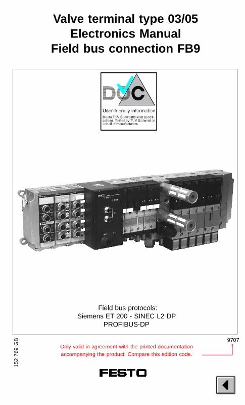
Valve terminal type 03/05Electronics Manual
Field bus connection FB9
Only valid in agreement with the printed documentationaccompanying the product! Compare this edition code.
Field bus protocols:Siemens ET 200 - SINEC L2 DP
PROFIBUS-DP
Author: E. Klotz, H.-J. Drung
Editor: H.-J. Drung, M. Holder
Layout: Festo, Dept. PV-IDM
Translation: D. Smith
Type setting: DUCOM
9707
(Festo AG & Co., 73726 Esslingen,Federal Republic of Germany, 1997)
The copying, distribution and utililization of thisdocument as well as the communication of itscontent to others without expressed authorizationis prohibited. Offenders will be held liable for thepayment of damages. All rights reserved, in par-ticular the right to carry out patent, utility modelor ornamental design registrations.P
rint
ed o
n 10
0% r
ecy
cled
pap
erVIFB9 - 03/05
9707 I
Order no.: 152769
Title: MANUAL
Designation: P.BE-VIFB9-03/05-GB
VIFB9 - 03/05
II 9707
Contents
GENERAL SAFETY INSTRUCTIONS
Designated use VIIITarget group IXImportant user instructions XDanger categories XPictograms XIInstructions on this manual XIIService XIV
Chapter 1 SYSTEM SUMMARY1.1 System summary 1-3
System structure 1-3Type 03: Description of components 1-5Type 05: Description of components 1-9Description of the functions 1-11
Chapter 2 FITTING2.1 Fitting the components 2-3
Input/output modules 2-4End plates 2-6Hat rail clamping unit 2-8
2.2 Type 03: Fitting the valve terminal 2-9Wall fitting 2-9Hat rail fitting 2-10
2.3 Type 05: Fitting the valve terminal 2-12Wall fitting 2-12
ContentsVIFB9 - 03/05
9707 III
Chapter 3 INSTALLATION3.1 General connection principles 3-3
Cable selection – field bus cable 3-4Cable selection – operating voltages 3-4Connecting the cables to theplugs/sockets 3-5
3.2 Field bus node 3-7Opening and closing the node 3-7
Configuring the valve terminal 3-9Setting the station numberand operating mode 3-10Summary of possible station numbers/station addresses 3-12Field bus baud rate and field bus length 3-14
3.2.1 Type 03:Connecting the operating voltages 3-15
3.2.2 Type 05:Connecting the operating voltages 3-22
3.2.3 Connecting the field bus 3-29Connection instructions 3-32Cable termination 3-33Cable termination network 3-34
3.3 Connecting the input modules 3-35Pin assignment 3-37
3.4 Connecting the output modules 3-38Pin assignment 3-40
VIFB9 - 03/05
IV 9707
Chapter 4 COMMISSIONING4.1 Basic principles of configuration
and addressing 4-5General 4-5Switching on the operating voltage 4-6Calculating the configuration data 4-7Calculating the number of inputs/outputs type 03 4-8Calculating the number of inputs/outputs type 05 4-9Summary of maximum number of I/Os 4-10Address assignment of the valve terminal 4-11General (types 03 and 05) 4-11Basic rule 1 4-12Basic rule 2 4-15Basic rule 3 4-15Address assignment afterextension/conversion 4-16Example of addressing type 03 MIDI/MAXI valves 4-19Example of addressing type 05 ISO valves 4-20
4.2 Siemens 4-21General 4-21Commissioning tips 4-23Profile selection 4-24Status bits 4-25FREEZE and SYNC 4-25Module consistency 4-25Sequence of configuration entries 4-26Station selection 4-26Station selection withCOM ET200 version 4.x 4-27Configuring COM ET200 v. 4.x 4-28
VIFB9 - 03/05
9707 V
Station selection with COM ET200 Windows 4-31Configuration COM ET200 Windows V2.x 4-33Station selection with STEP 7 V2.xor NCM S7-PROFIBUS V2.x 4-37Configuration NCM S7-L2 V1.1 4-44 Example 1 4-45 Example 2 4-46
4.3 General DP-master 4-47Status bits 4-47FREEZE and SYNC 4-48Module consistency 4-48Sequence of configuration entries 4-48Bus start 4-49 Send parametrizing data 4-50 Send configuration data 4-52 Request diagnostic information 4-53 Cyclic exchange of data 4-54Summary of implemented functions and service access points (SAP) 4-56Bus parameter/reaction times 4-56Device master file (GSD) 4-57 Examples 4-59 Example 1 4-59 Example 2 4-59
Chapter 5 DIAGNOSIS AND ERROR TREATMENT5.1 Summary of diagnostic possibilities 5-3
5.2 On-the-spot diagnosis 5-4LED displays 5-4Field bus node 5-4Valves 5-6Input/output modules 5-8
VIFB9 - 03/05
VI 9707
5.3 Testing the valves 5-9Starting/stopping the test routine 5-10
5.4 Status bits 5-11Position of status bits 5-13
5.5 Diagnosis via PROFIBUS-DP(DP-standard) 5-15General 5-15Diagnostic words 5-15Diagnostic possibilities 5-16Summary of diagnostic bytes 5-17
5.6 Diagnosis via SINEC L2-DP(DP-Siemens) 5-21General 5-21Summary of diagnostic bytes 5-21Diagnosis via programmer/PC 5-24
5.7 Diagnosis via PROFIBUS-DP(general DP-master) 5-25General 5-25Diagnostic information 5-26
5.8 Error treatment 5-30Reaction to faults in the control system 5-30 Siemens SIMATIC S5/S7 5-31 General DP master 5-31Short circuit / overload at an output module 5-32
Appendix A TECHNICAL APPENDIXTechnical specifications A-3Cable length and cross section A-7Examples of circuitry A-12
Appendix B INDEX
VIFB9 - 03/05
9707 VII
GENERAL SAFETY INSTRUCTIONS
Designated use
The valve terminal types 03/05 described in thismanual are designated exclusively for use asfollows:
• for controlling pneumatic and electricalactuators (valves and output modules)
• for interrogating electrical sensor signals bymeans of the input modules.
Use the valve terminals only as follows:
• as designated in the instructions
• in technically faultless condition
• without any modifications.
The specified limit values for pressures, tem-peratures, electrical data, moments, etc. must beobserved when additional commercially-availablecomponents such as sensors and actuators areconnected.
Please comply also with national and local safetylaws and regulations.
VIFB9 - 03/05 General safety instructions
VIII 9609

Target group
This manual is directed exclusively at technicianswho are trained in control and automationtechnology and who have experience in install-ing, commissioning, programming and diagnos-ing programmable logic controllers (PLC) andfield bus systems.
VIFB9 - 03/05 General safety instructions
9609 IX
IMPORTANT USER INSTRUCTIONS
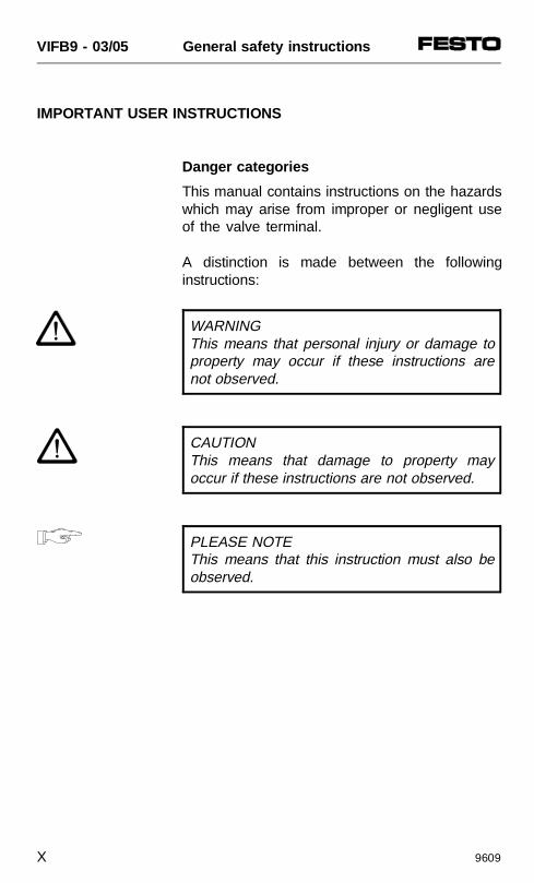
Danger categories
This manual contains instructions on the hazardswhich may arise from improper or negligent useof the valve terminal.
A distinction is made between the followinginstructions:
WARNINGThis means that personal injury or damage toproperty may occur if these instructions arenot observed.
CAUTIONThis means that damage to property mayoccur if these instructions are not observed.
PLEASE NOTEThis means that this instruction must also beobserved.
VIFB9 - 03/05 General safety instructions
X 9609
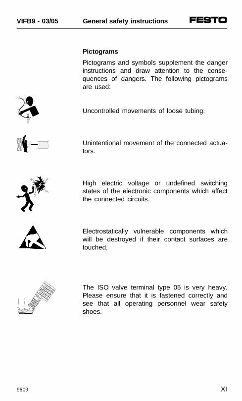
Pictog rams
Pictograms and symbols supplement the dangerinstructions and draw attention to the conse-quences of dangers. The following pictogramsare used:
Uncontrolled movements of loose tubing.
Unintentional movement of the connected actua-tors.
High electric voltage or undefined switchingstates of the electronic components which affectthe connected circuits.
Electrostatically vulnerable components whichwill be destroyed if their contact surfaces aretouched.
The ISO valve terminal type 05 is very heavy.Please ensure that it is fastened correctly andsee that all operating personnel wear safetyshoes.
VIFB9 - 03/05 General safety instructions
9609 XI
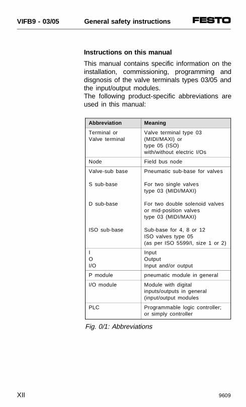
Instructions on this manual
This manual contains specific information on theinstallation, commissioning, programming anddisgnosis of the valve terminals types 03/05 andthe input/output modules.The following product-specific abbreviations areused in this manual:
Abbreviation Meaning
Terminal or Valve terminal
Valve terminal type 03(MIDI/MAXI) or type 05 (ISO) with/without electric I/Os
Node Field bus node
Valve-sub base
S sub-base
D sub-base
ISO sub-base
Pneumatic sub-base for valves
For two single valves type 03 (MIDI/MAXI)
For two double solenoid valvesor mid-position valves type 03 (MIDI/MAXI)
Sub-base for 4, 8 or 12 ISO valves type 05 (as per ISO 5599/I, size 1 or 2)
IOI/O
InputOutputInput and/or output
P module pneumatic module in general
I/O module Module with digitalinputs/outputs in general (input/output modules
PLC Programmable logic controller;or simply controller
Fig. 0/1: Abbreviations
VIFB9 - 03/05 General safety instructions
XII 9609
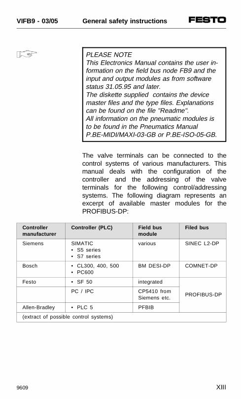
PLEASE NOTEThis Electronics Manual contains the user in-formation on the field bus node FB9 and theinput and output modules as from softwarestatus 31.05.95 and later.The diskette supplied contains the devicemaster files and the type files. Explanationscan be found on the file "Readme".All information on the pneumatic modules isto be found in the Pneumatics Manual P.BE-MIDI/MAXI-03-GB or P.BE-ISO-05-GB.
The valve terminals can be connected to thecontrol systems of various manufacturers. Thismanual deals with the configuration of thecontroller and the addressing of the valveterminals for the following control/addressingsystems. The following diagram represents anexcerpt of available master modules for thePROFIBUS-DP:
Controllermanufacturer
Controller (PLC) Field busmodule
Filed bus
Siemens SIMATIC • S5 series• S7 series
various SINEC L2-DP
Bosch • CL300, 400, 500• PC600
BM DESI-DP COMNET-DP
Festo • SF 50 integrated
PROFIBUS-DPPC / IPC CP5410 from
Siemens etc.
Allen-Bradley • PLC 5 PFBIB
(extract of possible control systems)
VIFB9 - 03/05 General safety instructions
9609 XIII
This manual describes the operation of the Festovalve terminals types 03-05 in conjunction withthe field bus protocols PROFIBUS-DP as per EN50170 (DIN 19245) part 3 and Siemens SINECL2-DP.
PLEASE NOTEIn conjunction with a Siemens SIMATIC S5,both the SINEC L2-DP and the PROFIBUS-DP protocols can be used; in conjunction withother PLCs, PCs, industrial PCs, thePROFIBUS-DP protocol must be set.In this manual, the protocol variants are desig-nated as follows:– DP-standard for PROFIBUS-DP– DP-Siemens for the SINEC L2-DP.
The valve terminal does not contain thePROFIBUS-FMS protocol (no combi-slavefunctions).
Service
If you have any technical problems, pleaseconsult your local Festo Service.
VIFB9 - 03/05 General safety instructions
XIV 9609
1. SYSTEM SUMMARY
VIFB9 - 03/05 1. User instructions
9707 1-1
Contents
1.1 SYSTEM SUMMARY 1-3
System structure 1-3Type 03: Description of components 1-5Type 05: Description of components 1-9Description of the functions 1-11
VIFB9 - 03/05 1. User instructions
1-2 9707
1.1 SYSTEM SUMMARY
System structure
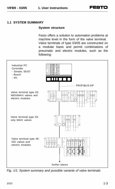
Festo offers a solution to automation problems atmachine level in the form of the valve terminal. Valve terminals of type 03/05 are constructed ona modular basis and permit combinations ofpneumatic and electric modules, such as thefollowing:
Valve terminal type 03:MIDI/MAXI valves andelectric modules
further slaves
Valve terminal type 03: only MAXI valves
Valve terminal type 05:ISO valves and electric modules
PROFIBUS-DP
Industrial PCController- Simatic S5/S7- Bosch- etc.
Fig. 1/1: System summary and possible variants of valve terminals
VIFB9 - 03/05 1. User instructions
9707 1-3
The valve terminal with field bus connectionoffers the following advantages:
• can be fitted with digital I/Os and pneumaticvalve locations
• subsequent extension/conversion possible• small-scale valves• can be connected to various control systems• less wiring due to two-core cables• clarity in system structure due to separation
of controller and machine• valves already fitted• wired (pilot) valve solenoid coils• central compressed air supply• central exhaust• device already tested
A field bus system also offers the followingadvantages:
• a reduction in the number of outputmodules in the controller
• economic data transfer over long distances• high baud rate• a large number of slaves can be connected• error diagnosis is made easier
VIFB9 - 03/05 1. User instructions
1-4 9707
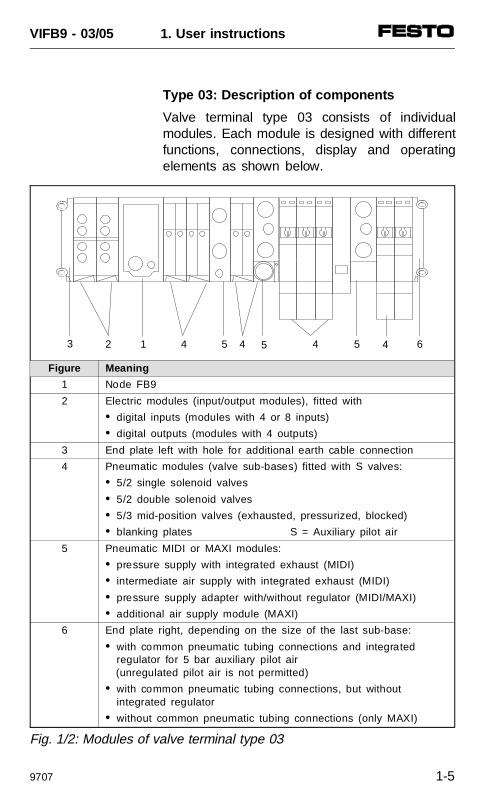
Type 03: Description of components
Valve terminal type 03 consists of individualmodules. Each module is designed with differentfunctions, connections, display and operatingelements as shown below.
3 2 4 51 4 655 44
Fig. 1/2: Modules of valve terminal type 03
Figure Meaning
1 Node FB9
2 Electric modules (input/output modules), fitted with
• digital inputs (modules with 4 or 8 inputs)
• digital outputs (modules with 4 outputs)
3 End plate left with hole for additional earth cable connection
4 Pneumatic modules (valve sub-bases) fitted with S valves:
• 5/2 single solenoid valves
• 5/2 double solenoid valves
• 5/3 mid-position valves (exhausted, pressurized, blocked)
• blanking plates S = Auxiliary pilot air
5 Pneumatic MIDI or MAXI modules:
• pressure supply with integrated exhaust (MIDI)
• intermediate air supply with integrated exhaust (MIDI)
• pressure supply adapter with/without regulator (MIDI/MAXI)
• additional air supply module (MAXI)
6 End plate right, depending on the size of the last sub-base:
• with common pneumatic tubing connections and integrated regulator for 5 bar auxiliary pilot air
(unregulated pilot air is not permitted)
• with common pneumatic tubing connections, but withoutintegrated regulator
• without common pneumatic tubing connections (only MAXI)
VIFB9 - 03/05 1. User instructions
9707 1-5
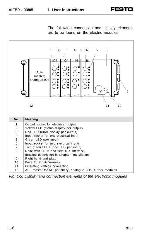
The following connection and display elementsare to be found on the electric modules:
No. Meaning
12345678
9101112
Output socket for electrical outputYellow LED (status display per output)Red LED (error display per output)Input socket for one electrical inputGreen LED (per input)Input socket for two electrical inputsTwo green LEDs (one LED per input)Node with LEDs and field bus interface,detailed description in Chapter "Installation"Right-hand end plateFuse for inputs/sensorsOperating voltage connectionAS-i master for I/O periphery; analogue I/Os; further modules
1 2 3 4 5 6 7 8
11 10
9
O4 O4 I4 I8
12
AS-imaster;
analogue IOs
Fig. 1/3: Display and connection elements of the electronic modules
VIFB9 - 03/05 1. User instructions
1-6 9707
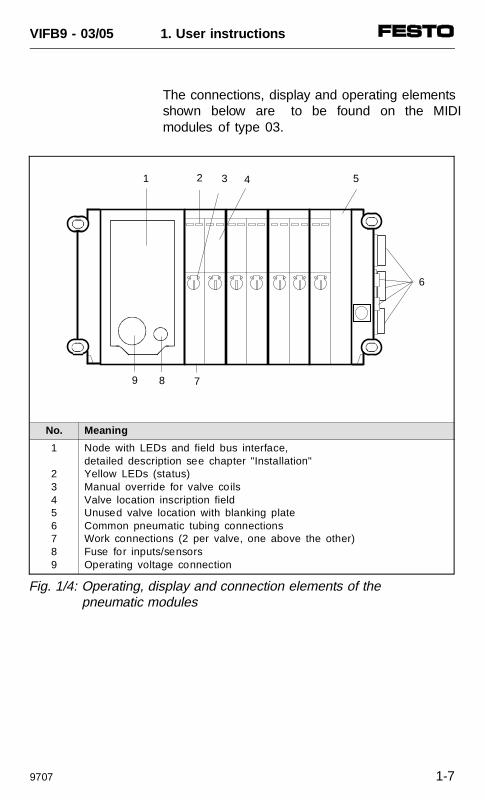
The connections, display and operating elementsshown below are to be found on the MIDImodules of type 03.
No. Meaning
1
23456789
Node with LEDs and field bus interface,detailed description see chapter "Installation"Yellow LEDs (status)Manual override for valve coilsValve location inscription fieldUnused valve location with blanking plateCommon pneumatic tubing connectionsWork connections (2 per valve, one above the other)Fuse for inputs/sensorsOperating voltage connection
2 3 4
6
9 8 7
51
Fig. 1/4: Operating, display and connection elements of the pneumatic modules
VIFB9 - 03/05 1. User instructions
9707 1-7
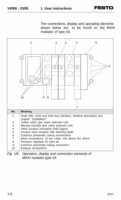
The connections, display and operating elementsshown below are to be found on the MAXImodules of type 03.
No. Meaning
1
2345678910
Node with LEDs and field bus interface, detailed description see chapter "Installation"Yellow LEDs (per valve solenoid coil)Manual override (per valve solenoid coil)Valve location inscription field (signs)Unused valve location with blanking plateCommon pneumatic tubing connectionsWork connections (2 per valve, one above the other)Pressure regulator for pilot airCommon pneumatic tubing connectionExhaust connections
31 2 4
6
10
5
7
89
Fig. 1/5: Operation, display and connection elements of MAXI modules type 03
VIFB9 - 03/05 1. User instructions
1-8 9707
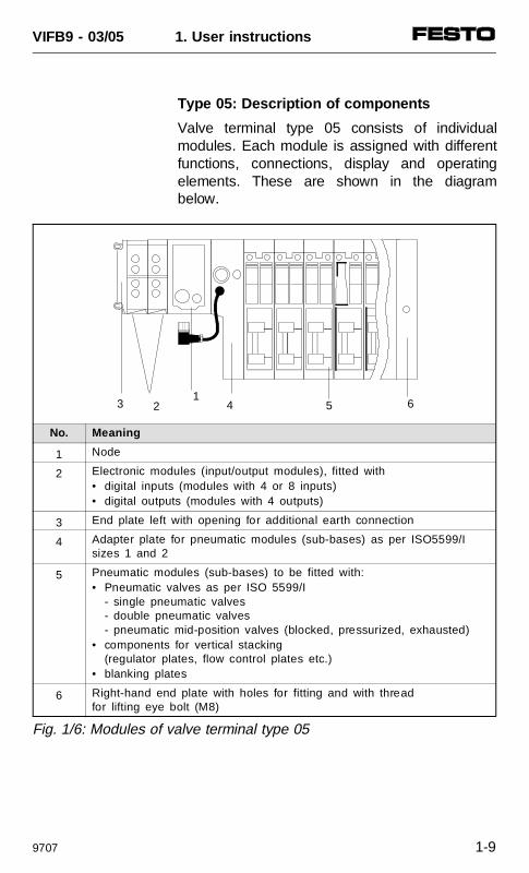
Type 05: Description of components
Valve terminal type 05 consists of individualmodules. Each module is assigned with differentfunctions, connections, display and operatingelements. These are shown in the diagrambelow.
No. Meaning
1 Node
2 Electronic modules (input/output modules), fitted with• digital inputs (modules with 4 or 8 inputs)• digital outputs (modules with 4 outputs)
3 End plate left with opening for additional earth connection
4 Adapter plate for pneumatic modules (sub-bases) as per ISO5599/Isizes 1 and 2
5 Pneumatic modules (sub-bases) to be fitted with:• Pneumatic valves as per ISO 5599/I
- single pneumatic valves- double pneumatic valves- pneumatic mid-position valves (blocked, pressurized, exhausted)
• components for vertical stacking (regulator plates, flow control plates etc.)
• blanking plates
6 Right-hand end plate with holes for fitting and with threadfor lifting eye bolt (M8)
3 2 41
5 6
Fig. 1/6: Modules of valve terminal type 05
VIFB9 - 03/05 1. User instructions
9707 1-9
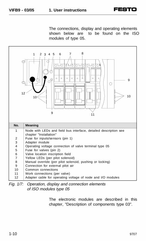
The connections, display and operating elementsshown below are to be found on the ISOmodules of type 05.
The electronic modules are described in thischapter, "Description of components type 03".
No. Meaning
1
23456789101112
Node with LEDs and field bus interface, detailed description see chapter "Installation"Fuse for inputs/sensors (pin 1)Adapter moduleOperating voltage connection of valve terminal type 05Fuse for valves (pin 2)Valve location inscription fieldYellow LEDs (per pilot solenoid)Manual override (per pilot solenoid, pushing or locking)Connection for external pilot airCommon connectionsWork connections (per valve)Adapter cable for operating voltage of node and I/O modules
1012
9 11
9
10
86 74 52 31
Fig. 1/7: Operation, display and connection elementsof ISO modules type 05
VIFB9 - 03/05 1. User instructions
1-10 9707
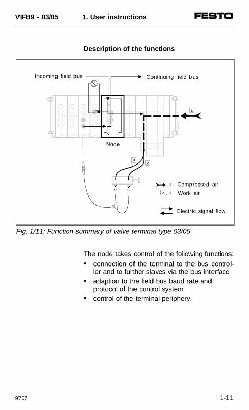
Description of the functions
The node takes control of the following functions:
• connection of the terminal to the bus control-ler and to further slaves via the bus interface
• adaption to the field bus baud rate and protocol of the control system
• control of the terminal periphery.
1
42 ,
42
1
AAAAAAAAA
AAAAAA Compressed air
Work air
Electric signal flow
Fig. 1/11: Function summary of valve terminal type 03/05
Incoming field bus Continuing field bus
Node
VIFB9 - 03/05 1. User instructions
9707 1-11
The input modules process the input signals(e.g. from sensors) and transmit these signalsvia the field bus to the bus controller. The outputmodules are universal electric outputs andcontrol low-current consuming devices with posi-tive logic, e.g. further valves, lights, etc..
The pneumatic modules create the followingconnection:
• common channels for supply and exhaust air• electric signals from all solenoid valve coils
On the individual pneumatic modules, the workconnections 2 and 4 have been provided foreach valve location.
The common channels on the pneumatic endplate or specific intermediate air supply modulesare used to supply the valves with compressedair and to remove the exhaust and pilot exhaust.Additionally intermediate air supply modules arealso available for the use of e.g. different workpressures, MIDI/MAXI valves or ISO valves.
Please see the pneumatic manuals for detailedinformation. Only the electric modules and thenode are described in this manual.
VIFB9 - 03/05 1. User instructions
1-12 9707

2. FITTING
VIFB9 - 03/05 2. Fitting
9609 2-1
Contents
2.1 FITTING THE COMPONENTS 2-3Input/output modules 2-4End plates 2-6Hat rail clamping unit 2-8
2.2 TYPE 03:FITTING THE VALVE TERMINAL 2-9Wall fitting 2-9Hat rail fitting 2-10
2.3 TYPE 05:FITTING THE VALVE TERMINAL 2-12Wall fitting (type 05) 2-12
VIFB9 - 03/05 2. Fitting
2-2 9609
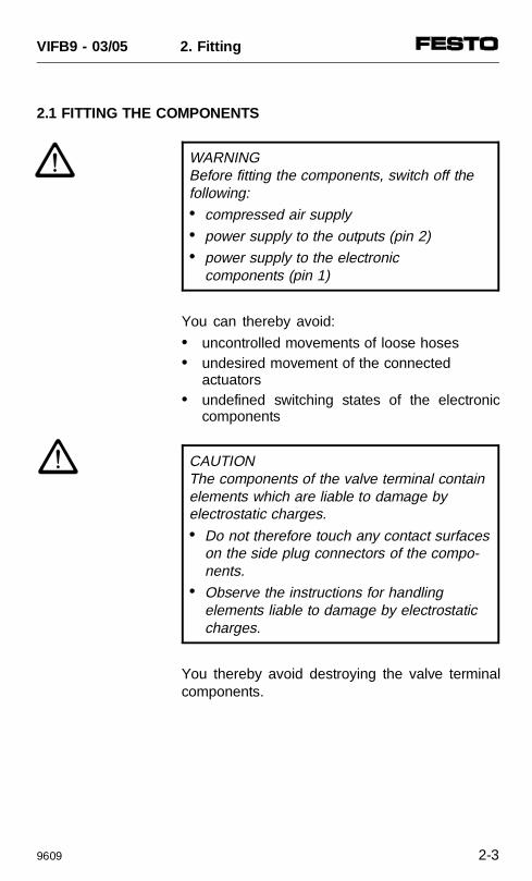
2.1 FITTING THE COMPONENTS
WARNINGBefore fitting the components, switch off thefollowing: • compressed air supply • power supply to the outputs (pin 2) • power supply to the electronic
components (pin 1)
You can thereby avoid:
• uncontrolled movements of loose hoses• undesired movement of the connected
actuators• undefined switching states of the electronic
components
CAUTION The components of the valve terminal containelements which are liable to damage by electrostatic charges. • Do not therefore touch any contact surfaces
on the side plug connectors of the compo-nents.
• Observe the instructions for handlingelements liable to damage by electrostatic charges.
You thereby avoid destroying the valve terminalcomponents.
VIFB9 - 03/05 2. Fitting
9609 2-3
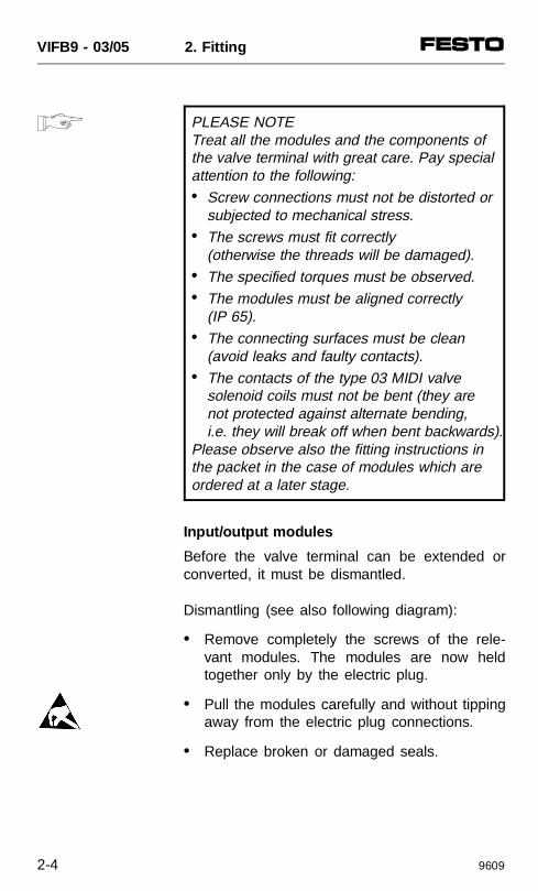
PLEASE NOTE Treat all the modules and the components ofthe valve terminal with great care. Pay specialattention to the following:• Screw connections must not be distorted or
subjected to mechanical stress. • The screws must fit correctly
(otherwise the threads will be damaged). • The specified torques must be observed. • The modules must be aligned correctly
(IP 65). • The connecting surfaces must be clean
(avoid leaks and faulty contacts). • The contacts of the type 03 MIDI valve
solenoid coils must not be bent (they are not protected against alternate bending, i.e. they will break off when bent backwards).
Please observe also the fitting instructions inthe packet in the case of modules which areordered at a later stage.
Input/output modules
Before the valve terminal can be extended orconverted, it must be dismantled.
Dismantling (see also following diagram):
• Remove completely the screws of the rele-vant modules. The modules are now heldtogether only by the electric plug.
• Pull the modules carefully and without tippingaway from the electric plug connections.
• Replace broken or damaged seals.
VIFB9 - 03/05 2. Fitting
2-4 9609
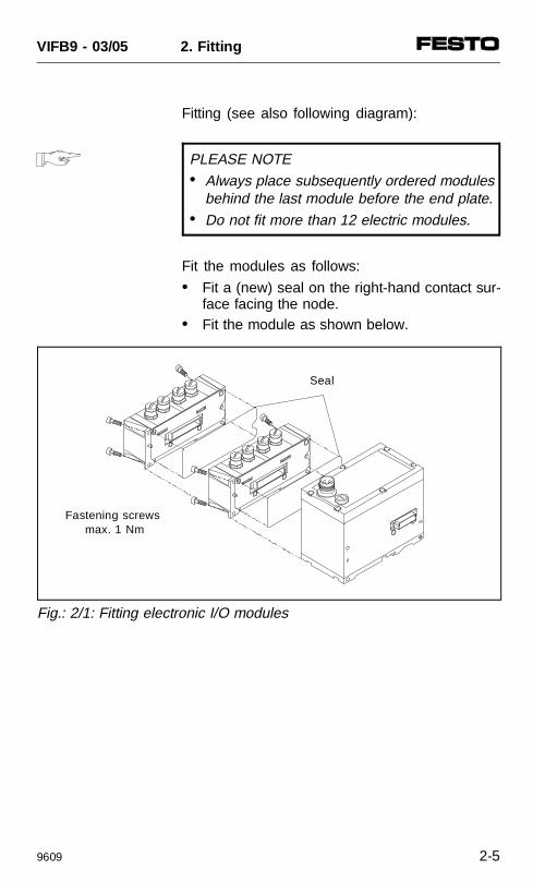
Fitting (see also following diagram):
PLEASE NOTE • Always place subsequently ordered modules
behind the last module before the end plate.• Do not fit more than 12 electric modules.
Fit the modules as follows:
• Fit a (new) seal on the right-hand contact sur-face facing the node.
• Fit the module as shown below.
Seal
Fastening screws max. 1 Nm
Fig.: 2/1: Fitting electronic I/O modules
VIFB9 - 03/05 2. Fitting
9609 2-5
End plates
A left-hand and a right-hand end plate arerequired as a mechanical termination of theterminal. These end plates fulfil the followingfunctions:
• They comply with protection class IP65.
• They contain connections/holes for the pro-tective earth cable.
• They contain holes for fitting on walls and tothe hat rail clamping unit.
The right-hand end plate of the ISO valveterminal is sufficiently grounded via the screwconnections and pre-fitted spring contacts of thesub-bases.
There are different types of right-hand end platefor valve terminals of type 03 (MIDI/MAXI). Allare supplied with pre-fitted earth cables.
CAUTION The right-hand end plate of valve terminal type03 must be grounded via the earth cablebefore it is fitted. This is to avoid high voltageson the metal surface in the case of a fault.
VIFB9 - 03/05 2. Fitting
2-6 9609
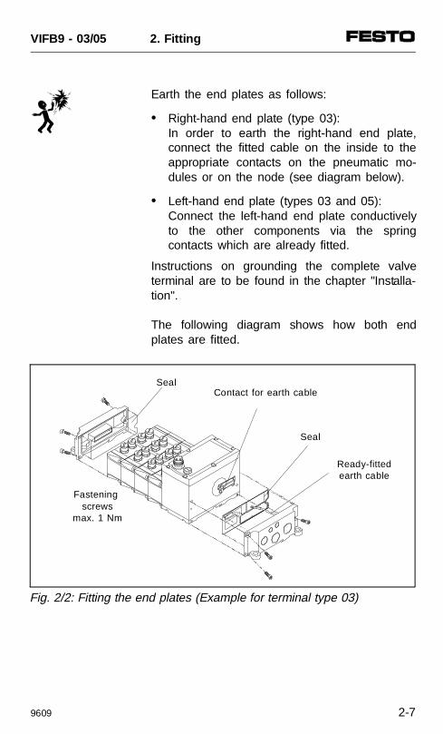
Earth the end plates as follows:
• Right-hand end plate (type 03): In order to earth the right-hand end plate,connect the fitted cable on the inside to theappropriate contacts on the pneumatic mo-dules or on the node (see diagram below).
• Left-hand end plate (types 03 and 05): Connect the left-hand end plate conductivelyto the other components via the springcontacts which are already fitted.
Instructions on grounding the complete valveterminal are to be found in the chapter "Installa-tion".
The following diagram shows how both endplates are fitted.
Seal
Fastening screws
max. 1 Nm
Ready-fittedearth cable
Contact for earth cableSeal
Fig. 2/2: Fitting the end plates (Example for terminal type 03)
VIFB9 - 03/05 2. Fitting
9609 2-7
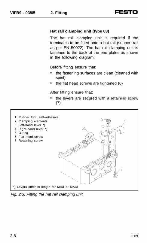
Hat rail clamping unit (type 03)
The hat rail clamping unit is required if theterminal is to be fitted onto a hat rail (support railas per EN 50022). The hat rail clamping unit isfastened to the back of the end plates as shownin the following diagram:
Before fitting ensure that:
• the fastening surfaces are clean (cleaned withspirit)
• the flat head screws are tightened (6)
After fitting ensure that:
• the levers are secured with a retaining screw(7).
1 Rubber foot, self-adhesive2 Clamping elements3 Left-hand lever *)4 Right-hand lever *)5 O ring6 Flat head screw7 Retaining screw
*) Levers differ in length for MIDI or MAXI
Fig. 2/3: Fitting the hat rail clamping unit
VIFB9 - 03/05 2. Fitting
2-8 9609
2.2 TYPE 03: FITTING THE VALVE TERMINAL
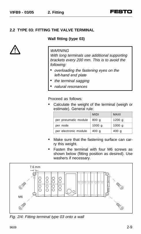
Wall fitting (type 03)
WARNINGWith long terminals use additional supportingbrackets every 200 mm. This is to avoid thefollowing:• overloading the fastening eyes on the
left-hand end plate• the terminal sagging• natural resonances
Proceed as follows:
• Calculate the weight of the terminal (weigh orestimate). General rule:
• Make sure that the fastening surface can car-ry this weight.
• Fasten the terminal with four M6 screws asshown below (fitting position as desired). Usewashers if necessary.
7.6 mm
M6
Fig. 2/4: Fitting terminal type 03 onto a wall
MIDI MAXI
per pneumatic module 800 g 1200 g
per node 1000 g 1000 g
per electronic module 400 g 400 g
VIFB9 - 03/05 2. Fitting
9609 2-9
Hat rail fitting (type 03)
The terminal is suitable for fitting onto a hat rail(support rail as per EN 50022). For this purposethere is a guide groove on the rear of allmodules for hanging the terminal on the hat rail.
CAUTION • Fasten the valve terminal onto the hat rail
with the hat rail clamping unit. • If the terminal is fitted in a sloping position
or at a point subjected to vibration, use screw (7) to protect the hat rail clamping unit against unintentional loosening/opening.
PLEASE NOTE • If fitted in a horizontal position and with a
non-vibrating load the hat rail clamping unitneed not to be fastened with screws (7).
• If there is no hat rail clamping unit on the terminal, it can be ordered and fitted at a later stage.The use of MIDI or MAXI clamping units depends on the end plate fitted (MIDI/MAXI).
Proceed as follows:
• Calculate the weight of the terminal (weigh orestimate). General rule:
MIDI MAXI
per pneumatic module 800 g 1200 g
per node 1000 g 1000 g
per electronic module 400 g 400 g
VIFB9 - 03/05 2. Fitting
2-10 9609
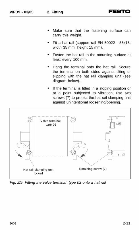
• Make sure that the fastening surface cancarry this weight.
• Fit a hat rail (support rail EN 50022 - 35x15;width 35 mm, height 15 mm).
• Fasten the hat rail to the mounting surface atleast every 100 mm.
• Hang the terminal onto the hat rail. Securethe terminal on both sides against tilting orslipping with the hat rail clamping unit (seediagram below).
• If the terminal is fitted in a sloping position orat a point subjected to vibration, use twoscrews (7) to protect the hat rail clamping unitagainst unintentional loosening/opening.
Hat rail clamping unitlocked
Retaining screw (7)
Valve terminal type 03
Fig. 2/5: Fitting the valve terminal type 03 onto a hat rail
VIFB9 - 03/05 2. Fitting
9609 2-11
2.3 TYPE 05: FITTING THE VALVE TERMINAL
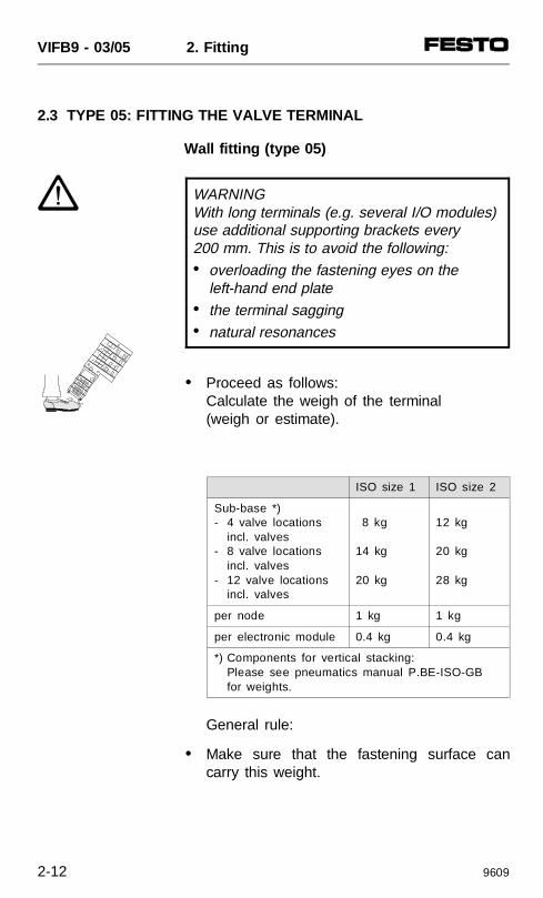
Wall fitting (type 05)
WARNINGWith long terminals (e.g. several I/O modules)use additional supporting brackets every 200 mm. This is to avoid the following:• overloading the fastening eyes on the
left-hand end plate• the terminal sagging• natural resonances
• Proceed as follows:Calculate the weigh of the terminal(weigh or estimate).
General rule:
• Make sure that the fastening surface cancarry this weight.
ISO size 1 ISO size 2
Sub-base *)- 4 valve locations
incl. valves- 8 valve locations
incl. valves- 12 valve locations
incl. valves
8 kg
14 kg
20 kg
12 kg
20 kg
28 kg
per node 1 kg 1 kg
per electronic module 0.4 kg 0.4 kg
*) Components for vertical stacking:Please see pneumatics manual P.BE-ISO-GBfor weights.
VIFB9 - 03/05 2. Fitting
2-12 9609
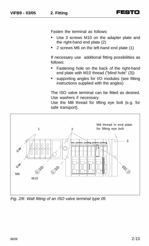
Fasten the terminal as follows:
• Use 3 screws M10 on the adapter plate andthe right-hand end plate (2)
• 2 screws M6 on the left-hand end plate (1)
If necessary use additional fitting possibilities asfollows:
• Fastening hole on the back of the right-handend plate with M10 thread ("blind hole" (3))
• supporting angles for I/O modules (see fittinginstructions supplied with the angles)
The ISO valve terminal can be fitted as desired.Use washers if necessary.Use the M8 thread for lifting eye bolt (e.g. forsafe transport).
M10
3
M8 thread in end platefor lifting eye bolt21
M6
Fig. 2/6: Wall fitting of an ISO valve terminal type 05
VIFB9 - 03/05 2. Fitting
9609 2-13

VIFB9 - 03/05 2. Fitting
2-14 9609

3. INSTALLATION
VIFB9 - 03/05 3. Installation
9707 3-1
Contents3.1 GENERAL CONNECTION
PRINCIPLES 3-3Cable selection – Field bus cable 3-4Cable selection – operating voltages 3-4Connecting the cables to the plugs/sockets 3-5
3.2 FIELD BUS NODE 3-7Opening and closing the node 3-7Configuring the valve terminal 3-9
Setting the station numberand operating mode 3-10Summary of possible stationaddresses/station numbers 3-12Field bus baud rate and field bus length 3-14
3.2.1 Type 03:Connecting the operating voltages 3-15
3.2.2 Type 05:Connecting the operating voltages 3-22
3.2.3 Connecting the field bus 3-29Connection instructions 3-32Cable termination 3-33Cable termination network 3-34
3.3 CONNECTING THE INPUT MODULES 3-35Pin assignment 3-37
3.4 CONNECTING THE OUTPUT MODULES 3-38Pin assignment 3-40
VIFB9 - 03/05 3. Installation
3-2 9707
3.1 GENERAL CONNECTION PRINCIPLES
WARNING Before installation or maintenance work is car-ried out, the following must be switched off: • the compressed air supply • power supply to the electronic components
(pin 1) • power supply to the outputs/valves (pin 2)
You thereby avoid:
• uncontrolled movements of loose tubing• undesired movements of the connected
actuators• undefined switching states of the electronic
components
VIFB9 - 03/05 3. Installation
9707 3-3
Cable selection – field bus cable
The field bus cable is a shielded twisted-pairwire. Please consult the PLC manual for thecontroller for the type of cable to be used. Thedistance and the field bus baud rate must alsobe taken into account.
Cable selection – operating voltages
Several parameters must be taken into accountwhen the two operating voltages are connected.Further information is to be found in the followingchapters:
• Chapter 3, InstallationSection: "Connecting the operating voltages"- Calculating the current consumption- Power unit design- Cable cross section and length
• APPENDIX A, Cable length and cross section- Determining the cross section and length
with tables- Calculating with a formula.
VIFB9 - 03/05 3. Installation
3-4 9707
Connecting the cables to the plugs/sockets
CAUTION The position of the pins on the plugs is differ-ent from that on the sockets. • The connections of the input and output
stages have been designed as sockets.• The connections of the field bus interface
and those of the operating voltage connection have been designed as plugs.
Please refer to the following chapters for thepin assignment.
When you have selected suitable cables, con-nect these according to steps 1...7 below.
1. Open the plugs/sockets as follows (see diagram):
• Power supply socket:Insert the power supply socket into theoperating voltage connection on the valveterminal. Unscrew the housing of thesocket, then remove the connection part ofthe socket which you have inserted intothe operating voltage connection.
• Sensor plug and bus interface socket:Unscrew the centre knurled nut.
VIFB9 - 03/05 3. Installation
9707 3-5
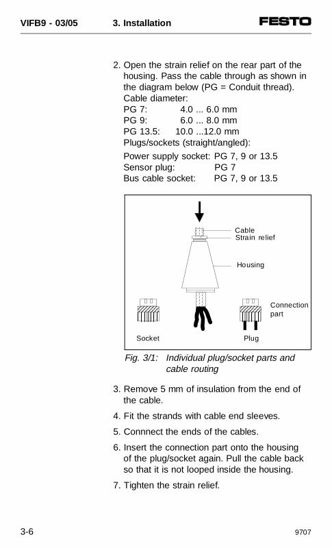
2. Open the strain relief on the rear part of thehousing. Pass the cable through as shown inthe diagram below (PG = Conduit thread).Cable diameter: PG 7: 4.0 ... 6.0 mm PG 9: 6.0 ... 8.0 mm PG 13.5: 10.0 ...12.0 mmPlugs/sockets (straight/angled):
Power supply socket: PG 7, 9 or 13.5Sensor plug: PG 7 Bus cable socket: PG 7, 9 or 13.5
3. Remove 5 mm of insulation from the end ofthe cable.
4. Fit the strands with cable end sleeves.
5. Connnect the ends of the cables.
6. Insert the connection part onto the housingof the plug/socket again. Pull the cable backso that it is not looped inside the housing.
7. Tighten the strain relief.
AAAAAAAAAAAAAAAAAAAA
AAAAAAAAA
AAAAAAAAAAAA
AAAAAAAAAAAAA
AAAAAAAA
AAAAAAAAA
AAAAAAAAAAAA
AAAAAAAAAAAAAAAA
AAAAAAAA
AAAAAAAAAAAA Connection
part
Cable
Housing
Strain relief
PlugSocket
Fig. 3/1: Individual plug/socket parts andcable routing
VIFB9 - 03/05 3. Installation
3-6 9707
3.2 FIELD BUS NODE
Opening and closing the node
WARNINGBefore installation or maintenance work is car-ried out, the following must be switched off: • compressed air supply• power supply to the electronic components
(pin 1)• power supply to the outputs/valves (pin 2)
You thereby avoid:
• uncontrolled movements of loose tubing
• undesired movements of the connected actu-ators
• undefined switching states of the electroniccomponents
CAUTION The components of the valve terminal containelements which are liable to damage by elec-trostatic charges. • Do not therefore touch any contact surfaces
on the side plug connectors of the compo-nents.
• Observe the instructions for handlingelements liable to damage by electrostatic charges.
You thereby avoid destroying the valve terminalcomponents.
VIFB9 - 03/05 3. Installation
9707 3-7
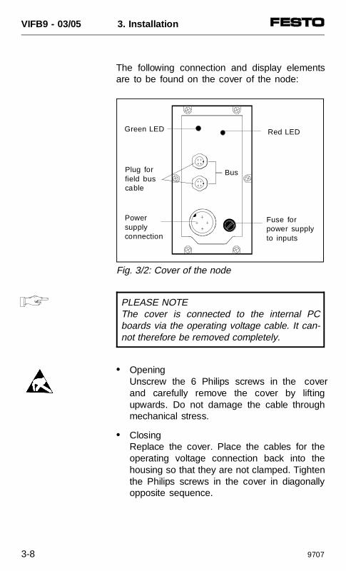
The following connection and display elementsare to be found on the cover of the node:
PLEASE NOTEThe cover is connected to the internal PCboards via the operating voltage cable. It can-not therefore be removed completely.
• OpeningUnscrew the 6 Philips screws in the coverand carefully remove the cover by liftingupwards. Do not damage the cable throughmechanical stress.
• ClosingReplace the cover. Place the cables for theoperating voltage connection back into thehousing so that they are not clamped. Tightenthe Philips screws in the cover in diagonallyopposite sequence.
Red LEDGreen LED
Powersupply connection
Plug for field bus cable
Fuse forpower supplyto inputs
Bus
Fig. 3/2: Cover of the node
VIFB9 - 03/05 3. Installation
3-8 9707
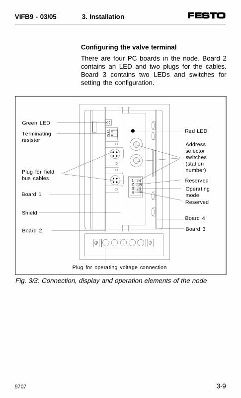
Configuring the valve terminal
There are four PC boards in the node. Board 2contains an LED and two plugs for the cables.Board 3 contains two LEDs and switches forsetting the configuration.
AAAAAAAA
AAAAAAAA
AAAAAAAA
AAAAAAAA
AAAAAAAAAAAA
1234
AAAA
AAAA
12
Red LED
Plug for fieldbus cables
Addressselectorswitches(stationnumber)
Shield
Board 1Operatingmode
Board 2
Plug for operating voltage connection
Green LED
Terminatingresistor
Board 4
Board 3
Reserved
Reserved
Fig. 3/3: Connection, display and operation elements of the node
VIFB9 - 03/05 3. Installation
9707 3-9
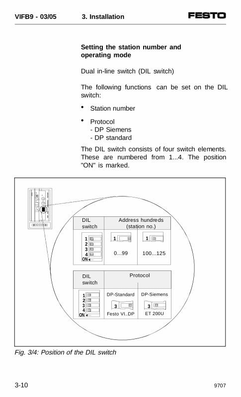
Setting the station number and operating mode
Dual in-line switch (DIL switch)
The following functions can be set on the DILswitch:
• Station number
• Protocol- DP Siemens- DP standard
The DIL switch consists of four switch elements.These are numbered from 1...4. The position"ON" is marked.
AAAAAA
AAAAAA
AAAAAA
AAAAAA
AAAA
AAAA
AAAAAA
AAAAAA
AAAAAA
AAAAAA
AAAA
3 AAAA
1 1
3
1234
1234
O
NO
N
AAA
DP-Siemens
ET 200U
DP-Standard
Festo VI..DP
0...99 100...125
Fig. 3/4: Position of the DIL switch
DILswitch
Address hundreds(station no.)
ProtocolDILswitch
VIFB9 - 03/05 3. Installation
3-10 9707
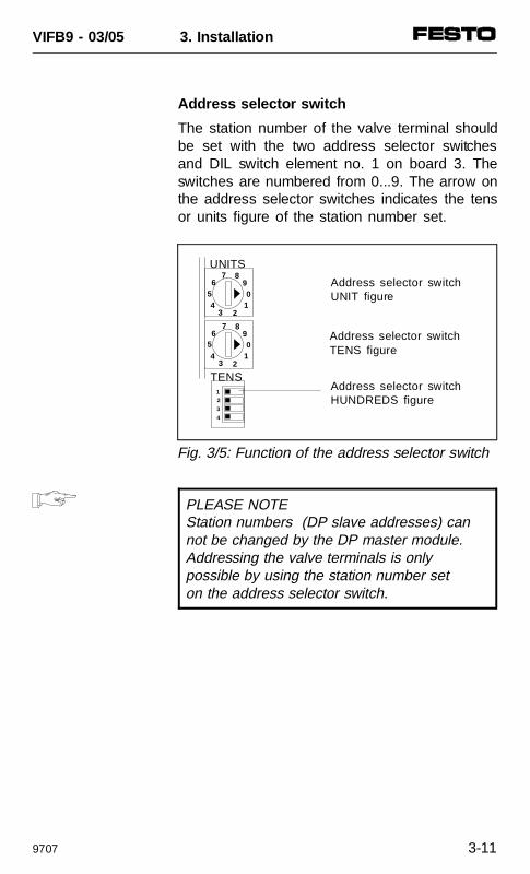
Address selector switch
The station number of the valve terminal shouldbe set with the two address selector switchesand DIL switch element no. 1 on board 3. Theswitches are numbered from 0...9. The arrow onthe address selector switches indicates the tensor units figure of the station number set.
PLEASE NOTEStation numbers (DP slave addresses) cannot be changed by the DP master module.Addressing the valve terminals is only possible by using the station number set on the address selector switch.
65
2
7 8
01
34
1
2
3
4
9
65
2
7 8
01
34
9
Address selector switchUNIT figure
Address selector switchHUNDREDS figure
UNITS
TENS
Address selector switchTENS figure
Fig. 3/5: Function of the address selector switch
VIFB9 - 03/05 3. Installation
9707 3-11
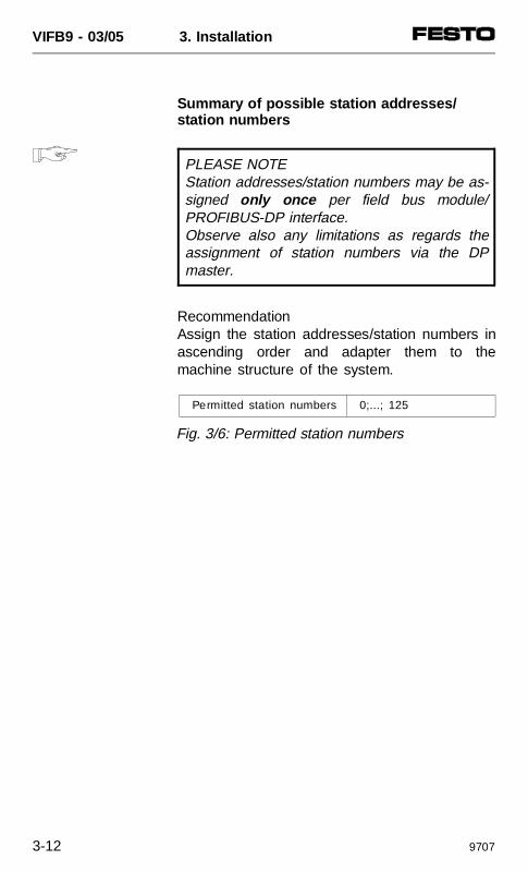
Summary of possible station addresses/station numbers
PLEASE NOTEStation addresses/station numbers may be as-signed only once per field bus module/PROFIBUS-DP interface. Observe also any limitations as regards theassignment of station numbers via the DPmaster.
RecommendationAssign the station addresses/station numbers inascending order and adapter them to themachine structure of the system.
Permitted station numbers 0;...; 125
Fig. 3/6: Permitted station numbers
VIFB9 - 03/05 3. Installation
3-12 9707
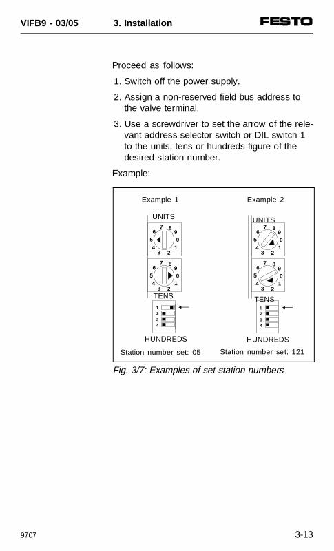
Proceed as follows:
1. Switch off the power supply.
2. Assign a non-reserved field bus address tothe valve terminal.
3. Use a screwdriver to set the arrow of the rele-vant address selector switch or DIL switch 1to the units, tens or hundreds figure of thedesired station number.
Example:
Fig. 3/7: Examples of set station numbers
12
34
65
2
7 8
01
34
9
65
2
7 8
01
34
9
TENS
HUNDREDS
UNITS
12
34
65
2
7 8
01
34
9
6
5
2
7 8
01
34
9
HUNDREDS
Example 1 Example 2
UNITS
TENS
Station number set: 121Station number set: 05
VIFB9 - 03/05 3. Installation
9707 3-13
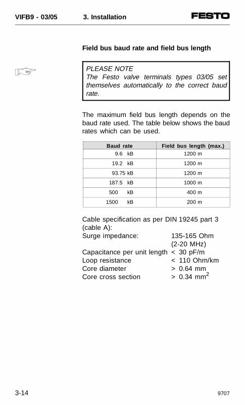
Field bus baud rate and field bus length
PLEASE NOTEThe Festo valve terminals types 03/05 setthemselves automatically to the correct baudrate.
The maximum field bus length depends on thebaud rate used. The table below shows the baudrates which can be used.
Cable specification as per DIN 19245 part 3(cable A):Surge impedance: 135-165 Ohm
(2-20 MHz)Capacitance per unit length < 30 pF/mLoop resistance < 110 Ohm/kmCore diameter > 0.64 mmCore cross section > 0.34 mm2
Baud rate Field bus length (max.) 9.6 kB 1200 m
19.2 kB 1200 m
93.75 kB 1200 m
187.5 kB 1000 m
500 kB 400 m
1500 kB 200 m
VIFB9 - 03/05 3. Installation
3-14 9707
3.2.1 Type 03: Connecting the operating voltages
WARNING In order that the operating voltage can be iso-lated reliably, you must use an isolating trans-former with at least 4 kV isolation resistancecomplying with standard EN 60742.
CAUTION The power supply to the outputs/valves (pin 2)must be separately fused externally with max.10 A. The external fuse prevents the valve ter-minal from being damaged in the event of ashort circuit.
VIFB9 - 03/05 3. Installation
9609 3-15
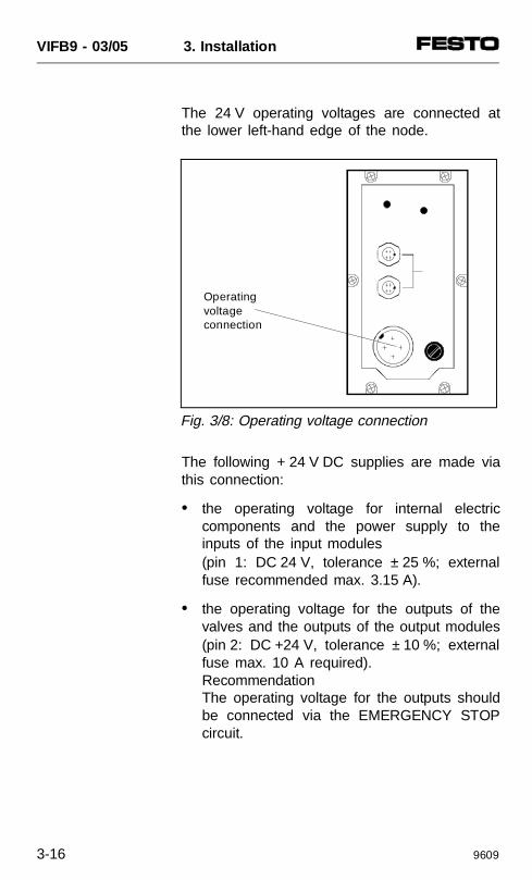
The 24 V operating voltages are connected atthe lower left-hand edge of the node.
The following + 24 V DC supplies are made viathis connection:
• the operating voltage for internal electriccomponents and the power supply to theinputs of the input modules(pin 1: DC 24 V, tolerance ± 25 %; externalfuse recommended max. 3.15 A).
• the operating voltage for the outputs of thevalves and the outputs of the output modules(pin 2: DC +24 V, tolerance ± 10 %; externalfuse max. 10 A required).RecommendationThe operating voltage for the outputs shouldbe connected via the EMERGENCY STOPcircuit.
Operatingvoltage connection
Fig. 3/8: Operating voltage connection
VIFB9 - 03/05 3. Installation
3-16 9609
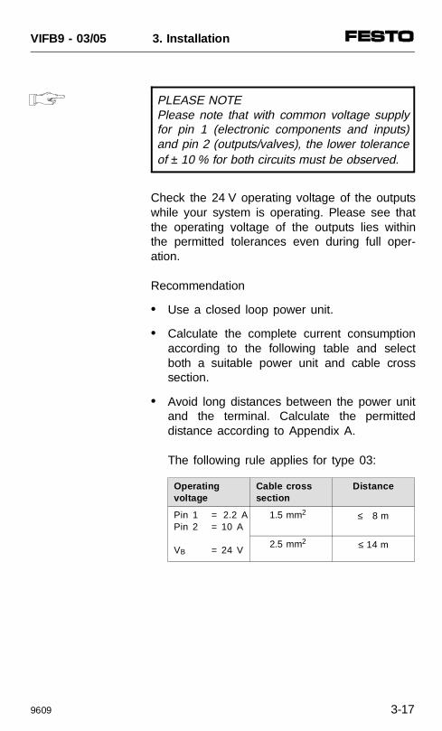
PLEASE NOTEPlease note that with common voltage supplyfor pin 1 (electronic components and inputs)and pin 2 (outputs/valves), the lower toleranceof ± 10 % for both circuits must be observed.
Check the 24 V operating voltage of the outputswhile your system is operating. Please see thatthe operating voltage of the outputs lies withinthe permitted tolerances even during full oper-ation.
Recommendation
• Use a closed loop power unit.
• Calculate the complete current consumptionaccording to the following table and selectboth a suitable power unit and cable crosssection.
• Avoid long distances between the power unitand the terminal. Calculate the permitteddistance according to Appendix A.
The following rule applies for type 03:
Operatingvoltage
Cable cross section
Distance
Pin 1 = 2.2 APin 2 = 10 A
VB = 24 V
1.5 mm2 ≤ 8 m
2.5 mm2 ≤ 14 m
VIFB9 - 03/05 3. Installation
9609 3-17
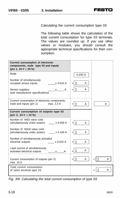
Calculating the current consumption type 03
The following table shows the calculation of thetotal current consumption for type 03 terminals.The values are rounded up. If you use othervalves or modules, you should consult theappropriate technical specifications for their con-sumption.
Current consumption of electronic components, node type 03 and inputs (pin 1, 24 V ± 25 %)
Node
Number of simultaneously occupied sensor inputs: _____x 0.010 A
Sensor supplies: _____x_____ A(see manufacturer specifications)
+
+
Current consumption of electronic components,node and inputs (pin 1) max. 2.2 A =
Current consumption of outputs type 03(pin 2, 24 V ± 10 %)
Number of MIDI valve coils(simultaneously under power): ____ x 0.055 A
Number of MAXI valve coils(simultaneously under power): ____ x 0.100 A
Number of simultaneously activated electrical outputs: ____ x 0.010 A
Load current of simultaneouslyactivated electrical outputs _____x_____A
+
+
+
+
Current consumption of outputs (pin 2) max. 10 A
= +
Total current consumptionof valve terminal type 03 =
∑ A
∑ A
∑ A
∑ A
∑ A
0.200 A
A
∑ A
∑ A
∑ A ∑ A
∑ A
Fig. 3/9: Calculating the total current consumption of type 03
VIFB9 - 03/05 3. Installation
3-18 9609
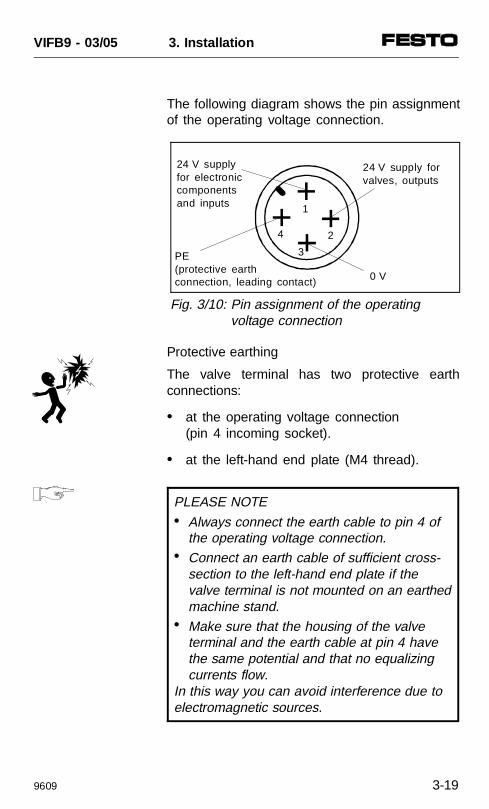
The following diagram shows the pin assignmentof the operating voltage connection.
Protective earthing
The valve terminal has two protective earthconnections:
• at the operating voltage connection(pin 4 incoming socket).
• at the left-hand end plate (M4 thread).
PLEASE NOTE• Always connect the earth cable to pin 4 of
the operating voltage connection. • Connect an earth cable of sufficient cross-
section to the left-hand end plate if the valve terminal is not mounted on an earthedmachine stand.
• Make sure that the housing of the valve terminal and the earth cable at pin 4 have the same potential and that no equalizing currents flow.
In this way you can avoid interference due toelectromagnetic sources.
0 V
PE(protective earth connection, leading contact)
4
1
2
3
24 V supplyfor electroniccomponentsand inputs
24 V supply forvalves, outputs
Fig. 3/10: Pin assignment of the operating voltage connection
VIFB9 - 03/05 3. Installation
9609 3-19
Connection example (type 03)
The following diagram shows the connection of acommon 24 V supply for pins 1 and 2. Pleasenote that:
• the outputs/valves must be protected againstshort circuit/overload with an external 10 Afuse
• the supply to the electronic components andinputs should be fused externally with 3.15 Aagainst short circuit/overload (recommenda-tion)
• the common tolerance of DC 24 V ± 10 %must be observed
• equalizing currents must be avoided whenboth earth cables are connected, e.g. bymeans of cables with appropriate crosssection as a potential compensation.
VIFB9 - 03/05 3. Installation
3-20 9609
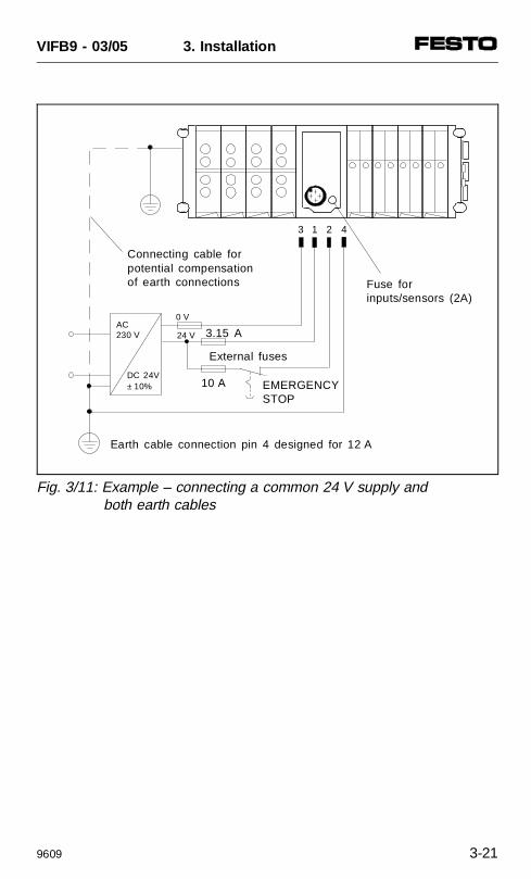
3 1 2 4
Earth cable connection pin 4 designed for 12 A
Connecting cable forpotential compensationof earth connections
External fuses
10 A
0 V
3.15 A
DC 24V± 10%
24 V
Fuse forinputs/sensors (2A)
EMERGENCYSTOP
AC230 V
Fig. 3/11: Example – connecting a common 24 V supply and both earth cables
VIFB9 - 03/05 3. Installation
9609 3-21
3.2.2 Type 05: Connecting the operating voltages
WARNING In order that the operating voltage can be iso-lated reliably, you must use an isolating trans-former with at least 4 kV isolation resistancecomplying with standard EN 60742.
CAUTION The power supply to the outputs/valves (pin 2)must be separately fused externally with max.10 A. The external fuse prevents the valve ter-minal from being damaged in the event of ashort circuit.
VIFB9 - 03/05 3. Installation
3-22 9609
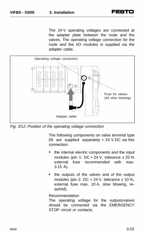
The 24 V operating voltages are connected atthe adapter plate between the node and thevalves. The operating voltage connection for thenode and the I/O modules is supplied via theadapter cable.
The following components on valve terminal type05 are supplied separately + 24 V DC via thisconnection:
• the internal electric components and the inputmodules (pin 1: DC + 24 V, tolerance ± 25 %external fuse recommended with max.3.15 A).
• the outputs of the valves and of the outputmodules (pin 2: DC + 24 V, tolerance ± 10 %,external fuse max. 10 A, slow blowing, re-quired).
RecommendationThe operating voltage for the outputs/valvesshould be connected via the EMERGENCYSTOP circuit or contacts.
Operating voltage connection
Adapter cable
Fuse for valves (4A slow blowing)
Fig. 3/12: Position of the operating voltage connection
VIFB9 - 03/05 3. Installation
9609 3-23
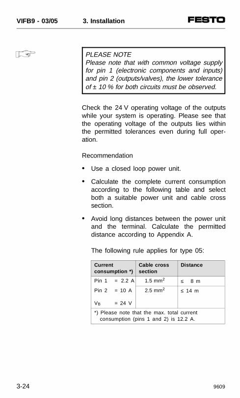
PLEASE NOTEPlease note that with common voltage supplyfor pin 1 (electronic components and inputs)and pin 2 (outputs/valves), the lower toleranceof ± 10 % for both circuits must be observed.
Check the 24 V operating voltage of the outputswhile your system is operating. Please see thatthe operating voltage of the outputs lies withinthe permitted tolerances even during full oper-ation.
Recommendation
• Use a closed loop power unit.
• Calculate the complete current consumptionaccording to the following table and selectboth a suitable power unit and cable crosssection.
• Avoid long distances between the power unitand the terminal. Calculate the permitteddistance according to Appendix A.
The following rule applies for type 05:
Current consumption *)
Cable cross section
Distance
Pin 1 = 2.2 A 1.5 mm2 ≤ 8 m
Pin 2 = 10 A
VB = 24 V
2.5 mm2 ≤ 14 m
*) Please note that the max. total currentconsumption (pins 1 and 2) is 12.2 A.
VIFB9 - 03/05 3. Installation
3-24 9609
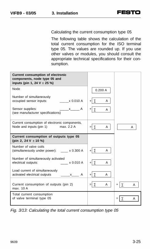
Calculating the current consumption type 05
The following table shows the calculation of thetotal current consumption for the ISO terminaltype 05. The values are rounded up. If you useother valves or modules, you should consult theappropriate technical specifications for their con-sumption.
Current consumption of electronic components, node type 05 andinputs (pin 1, 24 V ± 25 %)
Node
Number of simultaneously occupied sensor inputs: _____x 0.010 A
Sensor supplies: _____x_____ A(see manufacturer specifications)
+
+
Current consumption of electronic components,Node and inputs (pin 1) max. 2.2 A =
Current consumption of outputs type 05(pin 2, 24 V ± 10 %)
Number of valve coils(simultaneously under power): ____ x 0.300 A
Number of simultaneously activated electrical outputs: ____ x 0.010 A
Load current of simultaneouslyactivated electrical outputs _____x____ A
+
+
+
Current consumption of outputs (pin 2) max. 10 A
= +
Total current consumptionof valve terminal type 05 =
∑ A
∑ A
∑ A
∑ A
∑ A
0.200 A
A
∑ A
∑ A ∑ A
∑ A
Fig. 3/13: Calculating the total current consumption type 05
VIFB9 - 03/05 3. Installation
9609 3-25
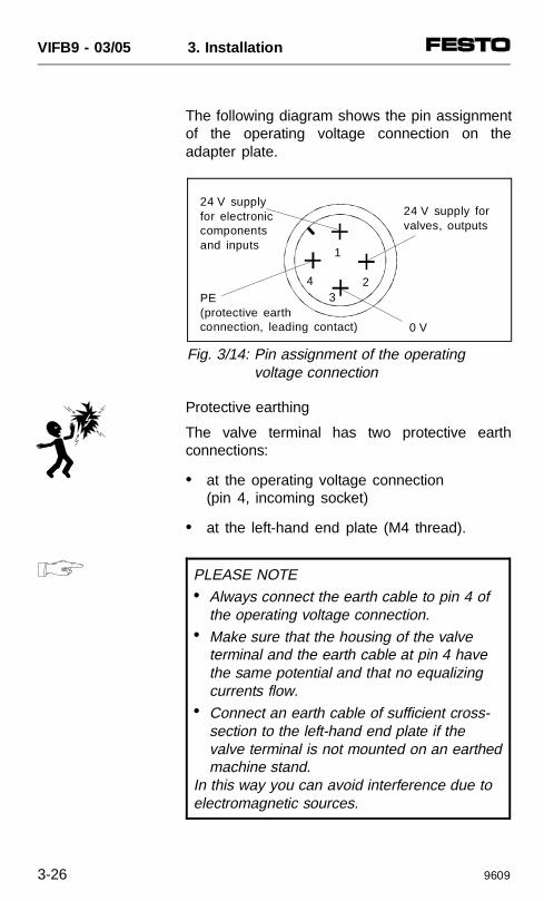
The following diagram shows the pin assignmentof the operating voltage connection on theadapter plate.
Protective earthing
The valve terminal has two protective earthconnections:
• at the operating voltage connection (pin 4, incoming socket)
• at the left-hand end plate (M4 thread).
PLEASE NOTE• Always connect the earth cable to pin 4 of
the operating voltage connection. • Make sure that the housing of the valve
terminal and the earth cable at pin 4 have the same potential and that no equalizing currents flow.
• Connect an earth cable of sufficient cross-section to the left-hand end plate if the valve terminal is not mounted on an earthedmachine stand.
In this way you can avoid interference due toelectromagnetic sources.
0 V
PE(protective earth connection, leading contact)
4
1
23
24 V supplyfor electroniccomponentsand inputs
24 V supply forvalves, outputs
Fig. 3/14: Pin assignment of the operating voltage connection
VIFB9 - 03/05 3. Installation
3-26 9609
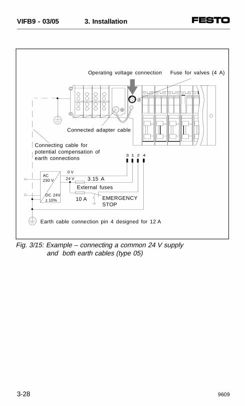
Connection example (type 05)
The following diagram shows the connection of acommon 24 V supply for pins 1 and 2. Pleasenote that:
• the outputs/valves must be protected againstshort circuit/overload with an external 10 Afuse (slow blowing)
• the supply to the electronic components andinputs should be fused externally with 3.15 Aagainst short circuit/overload (recommenda-tion)
• that the operating voltage of the sensors isseparately fused (2 A)
• that the operating voltage of the valves isseparately fused (4 A, slow blowing)
• the common tolerance of DC 24 V ± 10 %must be observed
• the operating voltage supply to the node ismade via the adapter cable
• equalizing currents must be avoided whenboth earth cables are connected, e.g. bymeans of cables with appropriate crosssection as a potential compensation.
VIFB9 - 03/05 3. Installation
9609 3-27
3 1 2 4
Earth cable connection pin 4 designed for 12 A
Connecting cable forpotential compensation ofearth connections
10 A
0 V
3.15 A
DC 24V± 10%
Connected adapter cable
Operating voltage connection
AC230 V
EMERGENCYSTOP
External fuses
Fuse for valves (4 A)
24 V
Fig. 3/15: Example – connecting a common 24 V supply and both earth cables (type 05)
VIFB9 - 03/05 3. Installation
3-28 9609
3.2.3 Connecting the field bus
There are two plugs on the node for connectingthe valve terminal to the field bus. One of theseconnections is for the incoming cable, the otherfor the continuing field bus cable. The signalcables of both plugs are connected internallywith each other.
This permits two types of connections:
• Looping the field bus cable from terminal toterminal; both field bus plugs are requiredhere.
• Connecting the field bus cable with a T-adapter; only one field bus plug is requiredhere.
VIFB9 - 03/05 3. Installation
9609 3-29
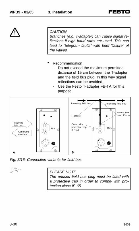
CAUTIONBranches (e.g. T-adapter) can cause signal re-flections if high baud rates are used. This canlead to "telegram faults" with brief "failure" ofthe valves.
• Recommendation- Do not exceed the maximum permitted
distance of 15 cm between the T-adapterand the field bus plug. In this way signal reflections can be avoided.
- Use the Festo T-adapter FB-TA for this purpose.
PLEASE NOTEThe unused field bus plug must be fitted witha protective cap in order to comply with pro-tection class IP 65.
Fig. 3/16: Connection variants for field bus
Bus
A B
BUS
Incoming field bus
Continuingfield bus
Incoming field bus Continuing field bus
T-adapterBranch linemax. 15 cm
Cover withprotective cap(IP 65)
VIFB9 - 03/05 3. Installation
3-30 9609
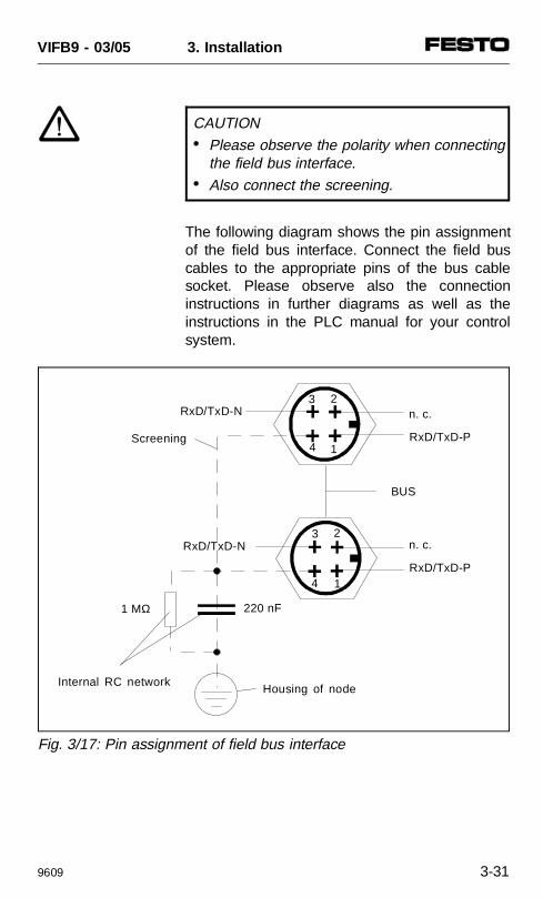
CAUTION• Please observe the polarity when connecting
the field bus interface. • Also connect the screening.
The following diagram shows the pin assignmentof the field bus interface. Connect the field buscables to the appropriate pins of the bus cablesocket. Please observe also the connectioninstructions in further diagrams as well as theinstructions in the PLC manual for your controlsystem.
Internal RC network
23
4 1
BUS
220 nF1 MΩ
Housing of node
Screening
RxD/TxD-N
3
4 1
2RxD/TxD-N
n. c.
RxD/TxD-P
n. c.
RxD/TxD-P
Fig. 3/17: Pin assignment of field bus interface
VIFB9 - 03/05 3. Installation
9609 3-31
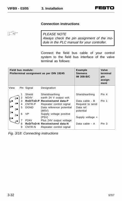
Connection instructions
PLEASE NOTEAlways check the pin assignment of the mo-dule in the PLC manual for your controller.
Connect the field bus cable of your controlsystem to the field bus interface of the valveterminal as follows:
59
48
2
6 1
37
Field bus module: Pin/terminal assignment as per DIN 19245
ExampleSiemensIM 308-B/C
Valveterminalpin assign-ment
View Pin
12345
6
789
Signal
ShieldM24VRxD/TxD-PCNTR-PDGND
VP
P24VRxD/TxD-NCNTR-N
Designation
Shield/earthingearth 24 V output volt.Receive/send data-PRepeater control signalData reference potential(M5V)Supply voltage positive(P5V)Plus 24V output voltageReceive/send data-NRepeater control signal
Shield/earthing
Data cable - BRequest to sendData ref.potential
Supply voltage +
Data cable - A
Pin 4
Pin 1
Pin 3
Fig. 3/18: Connecting instructions
VIFB9 - 03/05 3. Installation
3-32 9707
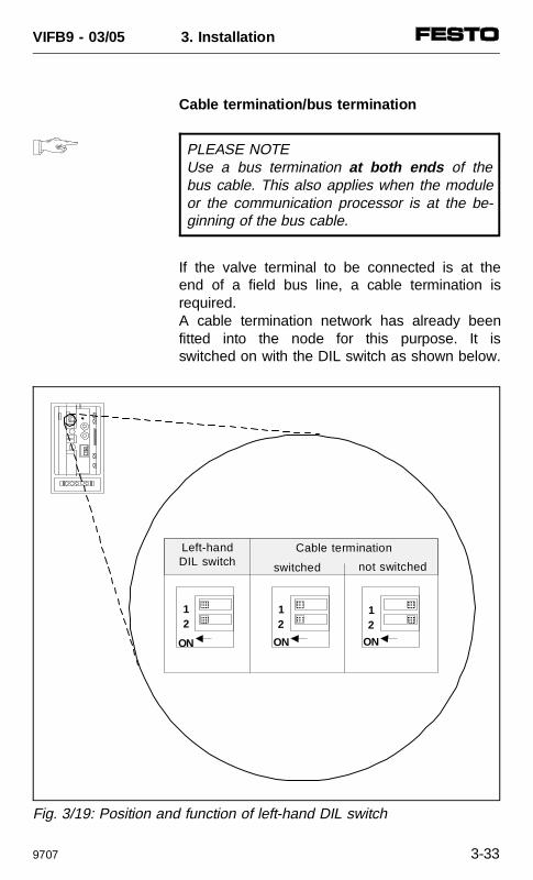
Cable termination/bus termination
PLEASE NOTEUse a bus termination at both ends of thebus cable. This also applies when the moduleor the communication processor is at the be-ginning of the bus cable.
If the valve terminal to be connected is at theend of a field bus line, a cable termination isrequired.A cable termination network has already beenfitted into the node for this purpose. It isswitched on with the DIL switch as shown below.
AAAAAA
AAAAAA
AAAA
12
ON
AAAAAAAAA
AAAAAA
AAAAAAAAA
AAAAAA
ON ON
12
12
Cable termination
not switchedswitched
Left-handDIL switch
Fig. 3/19: Position and function of left-hand DIL switch
VIFB9 - 03/05 3. Installation
9707 3-33
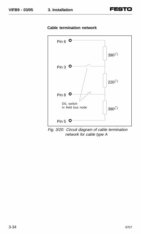
Cable termination network
390
220
390
Pin 6
Pin 3
Pin 8
Pin 5
DIL switchin field bus node
Fig. 3/20: Circuit diagram of cable termination network for cable type A
VIFB9 - 03/05 3. Installation
3-34 9707
3.3 CONNECTING THE INPUT MODULES
WARNING Before installation or maintenance work is car-ried out, the following must be switched off:• the compressed air supply• the power supply to the electronic
components (pin 1).• the power supply to the outputs/valves
(pin 2).
You thereby avoid:
• uncontrolled movements of loose tubing
• undesired movements of the connectedactuators
• undefined switching states of the electroniccomponents.
VIFB9 - 03/05 3. Installation
9609 3-35
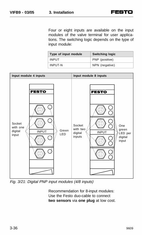
Four or eight inputs are available on the inputmodules of the valve terminal for user applica-tions. The switching logic depends on the type ofinput module:
Type of input module Switching logic
INPUT PNP (positive)
INPUT-N NPN (negative)
Input module 4 inputs Input module 8 inputs
Fig. 3/21: Digital PNP input modules (4/8 inputs)
Recommendation for 8-input modules:Use the Festo duo-cable to connecttwo sensors via one plug at low cost.
Socketwith onedigitalinput
Green LED
INPUT
Socketwith twodigitalinputs
OnegreenLED perdigitalinput
INPUT
VIFB9 - 03/05 3. Installation
3-36 9609
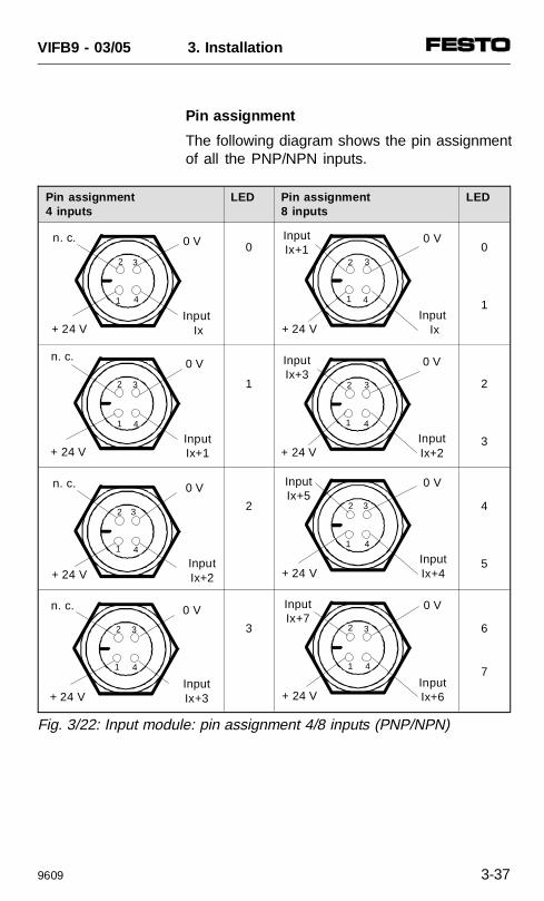
Pin assignment
The following diagram shows the pin assignmentof all the PNP/NPN inputs.
Pin assignment4 inputs
LED Pin assignment8 inputs
LED
0 0
1
1 2
3
2 4
5
3 6
7
Fig. 3/22: Input module: pin assignment 4/8 inputs (PNP/NPN)
0 V
Input Ix+ 24 V
n. c.
2
41
3
0 V
InputIx+1+ 24 V
n. c.
2
41
3
0 V
InputIx+2+ 24 V
n. c.
2
41
3
0 V
InputIx+3+ 24 V
n. c.
2
41
3
0 V
Input Ix+ 24 V
InputIx+1
2
41
3
0 V
InputIx+2+ 24 V
InputIx+3
2
41
3
0 V
InputIx+4+ 24 V
InputIx+5
2
41
3
0 V
InputIx+6+ 24 V
InputIx+7
2
41
3
VIFB9 - 03/05 3. Installation
9609 3-37

3.4 CONNECTING THE OUTPUT MODULES
WARNINGBefore installation or maintenance work is car-ried out, the following must be switched off: • the compressed air supply • the power supply to the electronic
components (pin 1). • the power supply to the outputs/valves
(pin 2).
You thereby avoid:
• uncontrolled movements of loose tubing
• undesired movements of the connectedactuators
• undefined switching states of the electroniccomponents.
VIFB9 - 03/05 3. Installation
3-38 9609
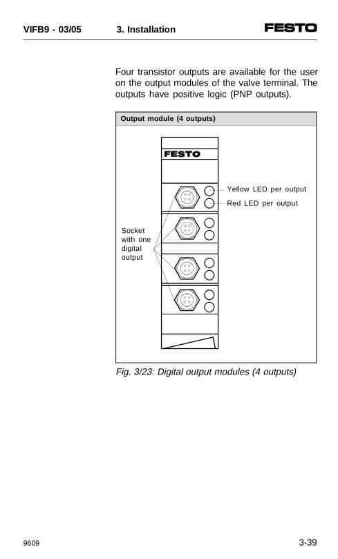
Four transistor outputs are available for the useron the output modules of the valve terminal. Theoutputs have positive logic (PNP outputs).
Output module (4 outputs)
Fig. 3/23: Digital output modules (4 outputs)
Socketwith onedigitaloutput
Yellow LED per output
Red LED per output
VIFB9 - 03/05 3. Installation
9609 3-39
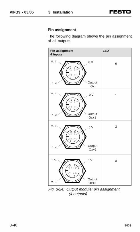
Pin assignment
The following diagram shows the pin assignmentof all outputs.
Pin assignment4 inputs
LED
0
1
2
3
0 V
OutputOx
n. c.
n. c.
2
41
3
0 V
OutputOx+1
n. c.
n. c.
2
41
3
0 V
OutputOx+2
n. c.
n. c.
2
41
3
0 V
OutputOx+3n. c.
n. c.
2
41
3
Fig. 3/24: Output module: pin assignment (4 outputs)
VIFB9 - 03/05 3. Installation
3-40 9609

4. COMMISSIONING
VIFB9 - 03/05 4. Commissioning
9707 4-1
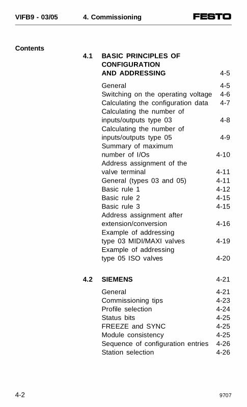
Contents4.1 BASIC PRINCIPLES OF
CONFIGURATIONAND ADDRESSING 4-5
General 4-5Switching on the operating voltage 4-6Calculating the configuration data 4-7Calculating the number of inputs/outputs type 03 4-8Calculating the number of inputs/outputs type 05 4-9Summary of maximum number of I/Os 4-10Address assignment of the valve terminal 4-11General (types 03 and 05) 4-11Basic rule 1 4-12Basic rule 2 4-15Basic rule 3 4-15Address assignment afterextension/conversion 4-16Example of addressing type 03 MIDI/MAXI valves 4-19Example of addressing type 05 ISO valves 4-20
4.2 SIEMENS 4-21
General 4-21Commissioning tips 4-23Profile selection 4-24Status bits 4-25FREEZE and SYNC 4-25Module consistency 4-25Sequence of configuration entries 4-26Station selection 4-26
VIFB9 - 03/05 4. Commissioning
4-2 9707
Station selection withCOM ET200 version 4.x 4-27Configuring COM ET200 version 4.x 4-28Station selection with COM ET200 Windows 4-31Configuration COM ET200 Windows version 2.x 4-33Station selection with STEP 7 V2.x or NCM S7-L2 V1.x 4-37Configuration with STEP 7 V2.xor NCM S7-L2 V1.x 4-39Configuring with NCM S7-L2 V1.1 4-44 Example 1 4-45 Example 2 4-46
4.3 GENERAL DP-MASTER 4-47
Status bits 4-47FREEZE and SYNC 4-48Module consistency 4-48Sequence of configuration entries 4-48Bus start 4-49 Send parametrizing data 4-50 Send configuration data 4-52 Request diagnostic information 4-53 Cyclic exchange of data 4-54Summary of implemented functions and service access points (SAP) 4-56Bus parameter/reaction times 4-56Device master file (GSD) 4-57 Example 1 4-59 Example 2 4-59
VIFB9 - 03/05 4. Commissioning
9707 4-3

VIFB9 - 03/05 4. Commissioning
4-4 9707
4.1 BASIC PRINCIPLES OF CONFIGURATION AND ADDRESSING
General
Before commissioning or programming, the usershould compile a configuration list for theconnected field bus slaves. On the basis of thislist he can:
• make a comparison between the ACTUALand NOMINAL configurations in order torecognise connection errors;
• access these specifications during the syntaxcheck of a program, in order to avoidaddressing errors.
The valve terminal must be configured veryaccurately, since different configurationspecifications may be necessary for each termi-nal due to the modular structure. Observe herealso the specifications in the following sections.
VIFB9 - 03/05 4. Commissioning
9707 4-5
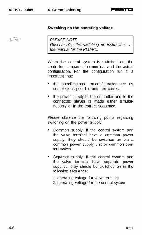
Switching on the operating voltage
PLEASE NOTEObserve also the switching on instructions inthe manual for the PLC/PC.
When the control system is switched on, thecontroller compares the nominal and the actualconfiguration. For the configuration run it isimportant that:
• the specifications on configuration are ascomplete as possible and are correct;
• the power supply to the controller and to theconnected slaves is made either simulta-neously or in the correct sequence.
Please observe the following points regardingswitching on the power supply:
• Common supply: If the control system andthe valve terminal have a common powersupply, they should be switched on via acommon power supply unit or common cen-tral switch.
• Separate supply: If the control system andthe valve terminal have separate powersupplies, they should be switched on in thefollowing sequence:
1. operating voltage for valve terminal2. operating voltage for the control system
VIFB9 - 03/05 4. Commissioning
4-6 9707
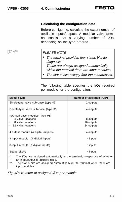
Calculating the configuration data
Before configuring, calculate the exact number ofavailable inputs/outputs. A modular valve termi-nal consists of a varying number of I/Os,depending on the type ordered.
PLEASE NOTE• The terminal provides four status bits for
diagnosis.These are always assigned automatically within the terminal there are input modules.
• The status bits occupy four input addresses.
The following table specifies the I/Os requiredper module for the configuration.
Module type Number of assigned I/Os*)
Single-type valve sub-base (type 03)
Double-type valve sub-base (type 05)
ISO sub-base modules (type 05)- 4 valve locations- 8 valve locations- 12 valve locations
4-output module (4 digital outputs)
4-input module (4 digital inputs)
8-input module (8 digital inputs)
Status bits**)
2 outputs
4 outputs
8 outputs16 outputs24 outputs
4 outputs
4 inputs
8 inputs
4 inputs
*) The I/Os are assigned automatically in the terminal, irrespective of whetheran input/output is actually used.
**) The status bits are assigned automatically in the terminal when there are input modules
Fig. 4/1: Number of assigned I/Os per module
VIFB9 - 03/05 4. Commissioning
9707 4-7
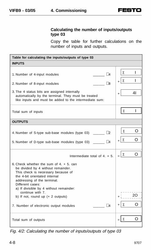
Calculating the number of inputs/outputstype 03
Copy the table for further calculations on thenumber of inputs and outputs.
Σ O
Table for calculating the inputs/outputs of type 03
INPUTS
1. Number of 4-input modules ______ ⋅ 4
2. Number of 8-input modules ______ ⋅ 8
3. The 4 status bits are assigned internally automatically by the terminal. They must be treated like inputs and must be added to the intermediate sum:
+
+
Total sum of inputs
OUTPUTS
4. Number of S-type sub-base modules (type 03) ______ ⋅ 2
5. Number of D-type sub-base modules (type 03) ______ ⋅ 4
+
Intermediate total of 4. + 5.
6. Check whether the sum of 4. + 5. can be divided by 4 without remainder.This check is necessary because of the 4-bit orientated internaladdressing of the terminal. Different cases:a) If divisible by 4 without remainder:
continue with 7.b) If not, round up (+ 2 outputs)
7. Number of electronic output modules ______ ⋅ 4
=
+
+
Total sum of outputs =
Σ I
4I
Σ I
Σ O
Σ O
Σ O
Σ O
Σ I
Fig. 4/2: Calculating the number of inputs/outputs of type 03
2O
VIFB9 - 03/05 4. Commissioning
4-8 9707
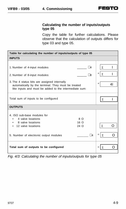
Calculating the number of inputs/outputstype 05
Copy the table for further calculations. Pleaseobserve that the calculation of outputs differs fortype 03 and type 05.
Table for calculating the number of inputs/outputs of type 05
INPUTS
1. Number of 4-input modules ______ ⋅ 4
2. Number of 8-input modules ______ ⋅ 8
3. The 4 status bits are assigned internally automatically by the terminal. They must be treated like inputs and must be added to the intermediate sum:
+
+
Total sum of inputs to be configured
OUTPUTS
4. ISO sub-base modules for• 4 valve locations 8 O• 8 valve locations 16 O• 12 valve locations 24 O
5. Number of electronic output modules _______ ⋅ 4 =
Total sum of outputs to be configured =
Σ I
4I
Σ I
Σ O
Σ O
Σ O
Σ I
Fig. 4/3: Calculating the number of inputs/outputs for type 05
VIFB9 - 03/05 4. Commissioning
9707 4-9
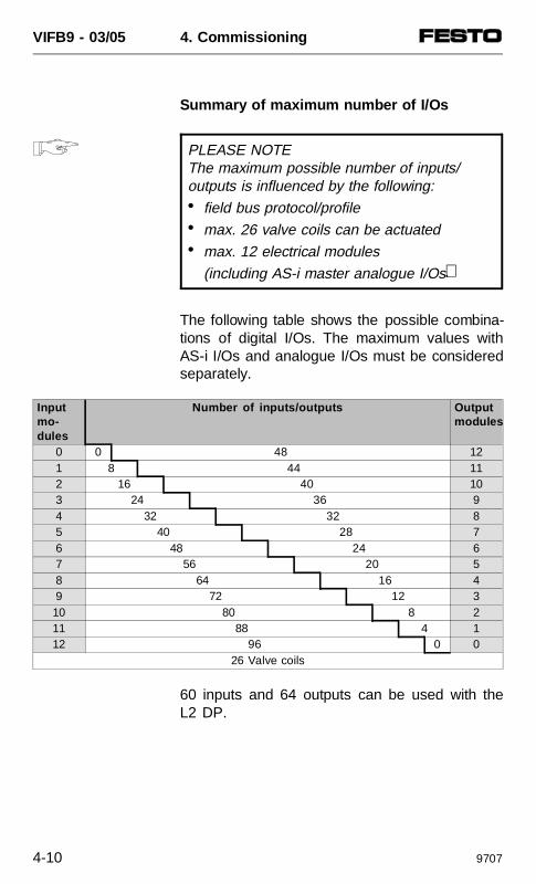
Summary of maximum number of I/Os
PLEASE NOTEThe maximum possible number of inputs/outputs is influenced by the following:• field bus protocol/profile• max. 26 valve coils can be actuated• max. 12 electrical modules
(including AS-i master analogue I/Os).
The following table shows the possible combina-tions of digital I/Os. The maximum values withAS-i I/Os and analogue I/Os must be consideredseparately.
Inputmo-dules
Number of inputs/outputs Outputmodules
0 0 48 121 8 44 112 16 40 103 24 36 94 32 32 85 40 28 76 48 24 67 56 20 58 64 16 49 72 12 310 80 8 211 88 4 112 96 0 0
26 Valve coils
60 inputs and 64 outputs can be used with theL2 DP.
VIFB9 - 03/05 4. Commissioning
4-10 9707
Address assignment of the valve terminal
General (types 03 and 05)
The address assignment of the outputs of amodular valve terminal depends on the numberof valve locations fitted on the terminal. Adistinction must be made between the followingfitting variants:
• valves and digital I/O modules• valves only• digital I/O modules only.
The basic rules described below apply to theaddress assignment of these fitting variants.Explicit examples of addressing valve terminalstype 03 and type 05 are described in separatechapters following these basic rules.
PLEASE NOTEIf one valve location occupies two addressesthe addresses are assigned as follows:• lower address ⇒
pilot solenoid coil 14• higher address ⇒
pilot solenoid coil 12
VIFB9 - 03/05 4. Commissioning
9707 4-11
Basic rule 1
With a mixed fitting, consideration is given tothe address assignment of the valves, digital I/Omodules and status bits.1. Outputs:
The address assignment of the outputs does not depend on the inputs.
1.1 Address assignment of valves:
• Addresses should be assigned in ascending order without gaps.
• Counting should begin on the nodefrom left to right.
• S-type sub-base mod. always occupy 2 add.
• D-type sub-base mod. always occupy 4 add.
• ISO valve locations always occupy 2 add.
• Maximum 26 solenoid valve coils can be add.
1.2 Round up to 4 bits: different cases: a) If the number of valve addresses can
be divided by 4 without remainder, continue with section 1.3.
b) If the number of valve addresses is notdivisible by 4 without remainder, it must be rounded up to 4 bits because of the 4-bit orientated addressing. The rounded up 2 bits in the addressrange cannot be used.
1.3 Address assignment of the output modules:The digital outputs are addressed after the(rounded up 4-bit) addresses of the valves.• Addresses should be assigned in
ascending order without gaps.• Counting should begin on the node
from right to left .• Counting on the individual modules
is from top to bottom.• Digital output modules always occupy
4 addresses.
VIFB9 - 03/05 4. Commissioning
4-12 9707
2. Inputs:The address assignment of the inputs does not depend on the outputs.
2.1 Address assignment of the input modules:
• Addresses should be assigned in ascending order without gaps.
• Counting should begin onthe node from right to left.
• Counting on the individual module is from top to bottom.
• 4-input modules occupy 4 addresses.
• 8-input modules occupy 8 addresses.2.2 Status bits
The addressing of the status bits depends on the output fittings and on the configuration.
The following always applies:• The status bits are only available when input
modules are connected to the terminal and
when at least eight inputs are configured in the PLC.
• Addressing. The status bits are transferredto the four highest positions on the con-figured address range.
When the operating voltage is switched on, thevalve terminal automatically recognises all avail-able pneumatic modules (type 03: max. 13modules; type 05: 4, 8 or 12 valve locations) anddigital input/output modules and assigns theappropriate addresses. If a valve location re-mains unused (blanking plate) or if a digitalinput/output is not connected, the appropriateaddress is still assigned.
VIFB9 - 03/05 4. Commissioning
9707 4-13
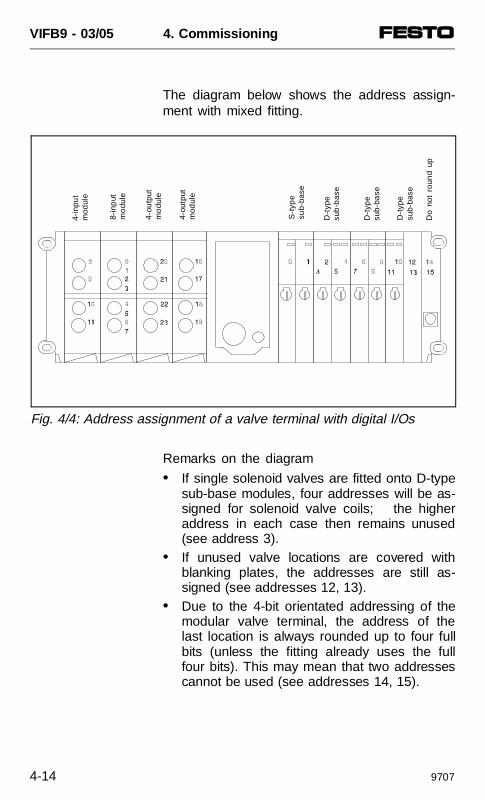
The diagram below shows the address assign-ment with mixed fitting.
Remarks on the diagram
• If single solenoid valves are fitted onto D-typesub-base modules, four addresses will be as-signed for solenoid valve coils; the higheraddress in each case then remains unused(see address 3).
• If unused valve locations are covered withblanking plates, the addresses are still as-signed (see addresses 12, 13).
• Due to the 4-bit orientated addressing of themodular valve terminal, the address of thelast location is always rounded up to four fullbits (unless the fitting already uses the fullfour bits). This may mean that two addressescannot be used (see addresses 14, 15).
Do
not
roun
d up
4-in
put
mod
ule
8-in
put
mo
dule
4-ou
tput
mo
dule
4-ou
tput
mod
ule
S-t
ype
sub-
base
D-t
ype
sub
-bas
e
D-t
ype
sub-
base
D-t
ype
sub-
base
Fig. 4/4: Address assignment of a valve terminal with digital I/Os
VIFB9 - 03/05 4. Commissioning
4-14 9707
Basic rule 2
If only valves are used, the address assignmentis always as described in basic rule 1.
PLEASE NOTE• Maximum 26 solenoid valve coils
can be addressed. • There is no rounding up of the last two
positions on the valve side. • Valve terminals without input modules do notrequire a configuration of inputs. Status bitsare then not available.
Basic rule 3
If only electrical I/Os are used, the addressassignment is always the same as in basicrule 1.
PLEASE NOTE• Counting begins immediately to the left of
the node.• There is no rounding up of the last
two positions on the valve side.
Please unfold for page S. 4-14
VIFB9 - 03/05 4. Commissioning
9707 4-15
Address assignment after extension/conversion
A special feature of the modular valve terminal isits flexibility. If the demands placed on themachine change, then the number of valvesfitted on the terminal can also be modified.
CAUTIONIf extensions or conversions are made to theterminal at a later stage, this may result in ashifting of the input/output addresses. Thisapplies in the following cases:
• If one or more pneumatic modules is/arefitted/removed at a later stage (type 03).
• If an S-type sub-base module with singlesolenoid valves is replaced by a D-typemodule with double solenoid valvesor vice versa (type 03).
• If additional input/output stages are insertedbetween the node and existing input/outputmodules.
• If existing 4-input modules are replacedby 8-input modules or vice versa.
These modifications may also requireconfiguration modifications to the master.
If the configuration of the inputs is modified, theaddresses of the status bits will be shifted.
VIFB9 - 03/05 4. Commissioning
4-16 9707
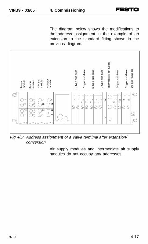
The diagram below shows the modifications tothe address assignment in the example of anextension to the standard fitting shown in theprevious diagram.
Air supply modules and intermediate air supplymodules do not occupy any addresses.
4-in
put
mod
ule
8-in
put
mo
dule
4-o
utpu
tm
odul
e
4-ou
tput
mod
ule
S-t
ype
sub-
base
D-t
ype
sub
-bas
e
Do
not
roun
d up
D-t
ype
sub-
base
D-t
ype
su
b-ba
se
D-t
ype
sub
-bas
r
S-t
ype
sub-
base
Inte
rmed
iate
air
sup
ply
Fig 4/5: Address assignment of a valve terminal after extension/conversion
VIFB9 - 03/05 4. Commissioning
9707 4-17
Please unfold for page 4-19
VIFB9 - 03/05 4. Commissioning
4-18 9707
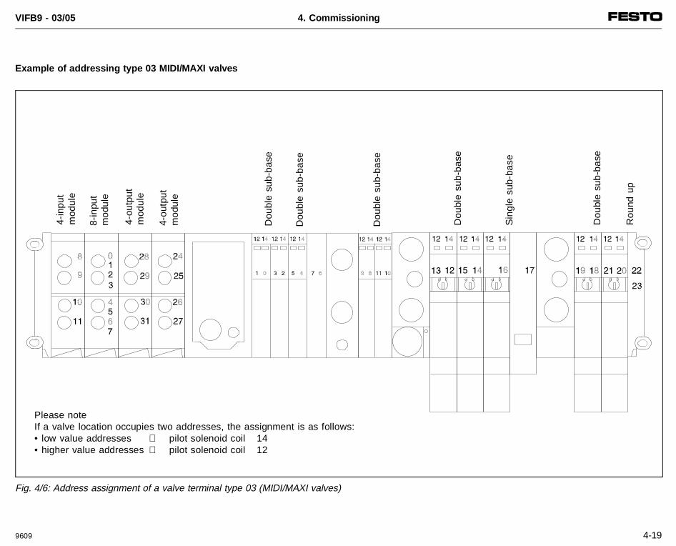
Example of addressing type 03 MIDI/MAXI valves
Please noteIf a valve location occupies two addresses, the assignment is as follows:• low value addresses ⇒ pilot solenoid coil 14• higher value addresses ⇒ pilot solenoid coil 12
4-in
put
mod
ule
8-in
put
mod
ule
4-ou
tput
mod
ule
4-ou
tput
mod
ule
Sin
gle
sub-
base
Dou
ble
sub-
base
Rou
nd u
p
Dou
ble
sub-
base
Dou
ble
sub-
base
Dou
ble
sub-
base
Dou
ble
sub-
base
Fig. 4/6: Address assignment of a valve terminal type 03 (MIDI/MAXI valves)
VIFB9 - 03/05 4. Commissioning
9609 4-19
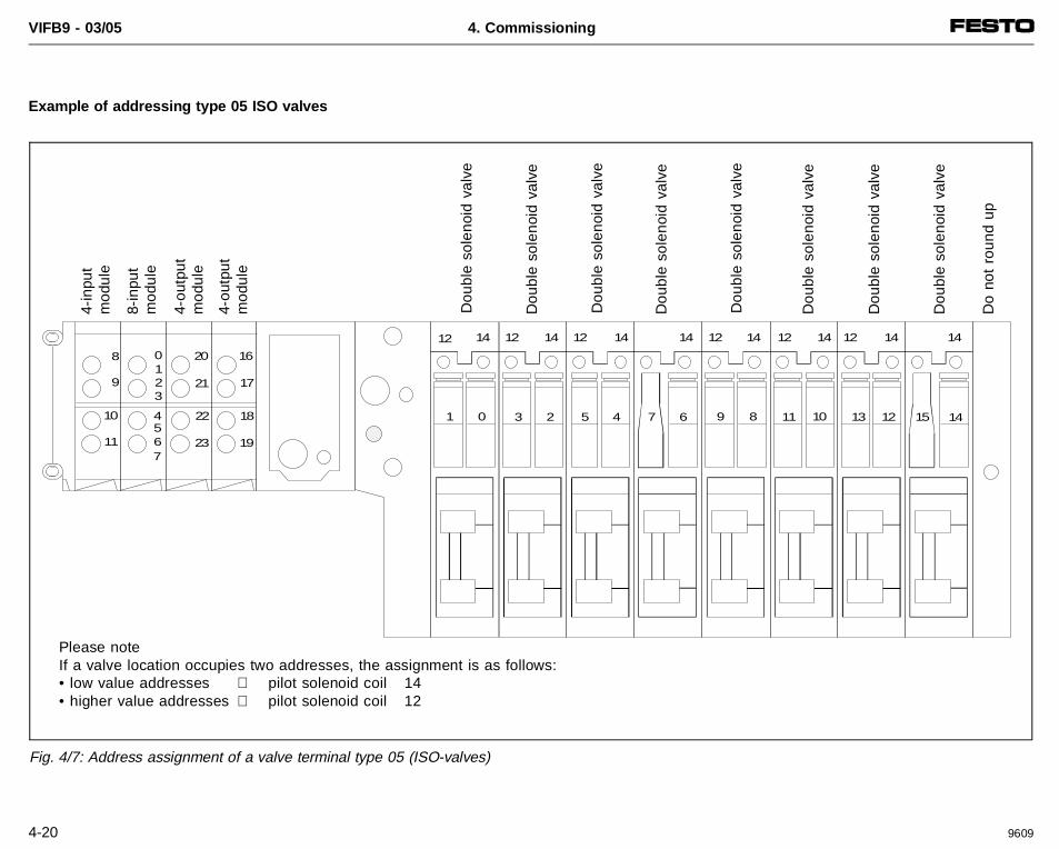
Example of addressing type 05 ISO valves
9 11 15 14
8 16
9
2
173
10
11
45
0
7
18
196
1
13
12
4 61 3 5 70 128 10
2
14 12 14 12 14 12 14 12 14 12 14 14
20
21
22
23
14
Please noteIf a valve location occupies two addresses, the assignment is as follows:• low value addresses ⇒ pilot solenoid coil 14• higher value addresses ⇒ pilot solenoid coil 12
4-in
put
mod
ule
8-in
put
mod
ule
4-ou
tput
mod
ule
4-ou
tput
mod
ule
Dou
ble
sole
noid
val
ve
Dou
ble
sole
noid
val
ve
Do
not
roun
d up
Dou
ble
sole
noid
val
ve
Dou
ble
sole
noid
val
ve
Dou
ble
sole
noid
val
ve
Dou
ble
sole
noid
val
ve
Dou
ble
sole
noid
val
ve
Dou
ble
sole
noid
val
ve
Fig. 4/7: Address assignment of a valve terminal type 05 (ISO-valves)
VIFB9 - 03/05 4. Commissioning
4-20 9609
4.2 SIEMENS
General
This chapter describes the entries required forconfiguring a valve terminal for a Siemens DPmaster. In order to understand this chapter, youmust use your configuration program correctly.
The valve terminal with node FB9 supports twoprotocols:
• DP Siemens and
• DP standard
These two protocol variants are also known asbus profiles. The protocols differ from each otheronly slightly. You can select the protocol youwish to use.
PLEASE NOTEYou should select the DP standard protocolif the following are integrated in the valve ter-minal:• the AS-i master and/or • analogue I/O mo dules.These additional functions are only availablein conjunction with the DP standard protocol.
VIFB9 - 03/05 4. Commissioning
9707 4-21
Different configuration programs are available,depending on the control system used (S5,S7, ...).
Examples
• COM ET200 (DOS version)• COM ET200 (Windows version)• SINEC NCM S7 PROFIBUS• STEP 7 (V2.X)• SINEC NCM• ...
The configuration programs are subject to modi-fications which may not already have been takeninto account in this manual.
VIFB9 - 03/05 4. Commissioning
4-22 9707
Commissioning tips
PLEASE NOTEYou must observe the following points in orderto guarantee reliable operation of your applica-tions with the Festo valve terminal.
• Insert the IM 308-B, IM 308-C, CP xx etc.into the correct location on your automationdevice.
• The ET200 location number bears no rela-tionship to the physical arrangement of theinput/output modules.
• Observe any limitations in the number ofdigital inputs/outputs e.g. CPU 941. max. 512.
• The station number set does not correspondto the configured periphery address.
• When configuring the outputs (e.g. 8DO 8DO8DO), note that the number and type ofpneumatic sub-bases is decisive, and notthe number of valves fitted.
• The periphery addresses of automation de-vice modules must not be the same as theconfigured periphery addresses.
• The number of input bits always increases by4 (= status bits).
• Reserved addresses for future requirementsare not permitted.
• Switch on terminating resistor on both sides.
VIFB9 - 03/05 4. Commissioning
9707 4-23
Profile selection
Use the DP standard protocol, in order to makeuse of the extended functions of the modularvalve terminal.
The profile selection is different in the individualconfiguration programs. Please refer to theappropriate manuals for details.
PLEASE NOTESome software packages no longer containany profile selection (e.g. STEP 7 V2.1). Inthis case, always use the DP standard proto-col.
Recommendation:Use the PROFIBUS-DP protocol.
VIFB9 - 03/05 4. Commissioning
4-24 9707
Status bits
The valve terminal always makes 4 status bits(= inputs) available for diagnostic purposes, if thevalve terminal is fitted with at least one inputmodule (4 or 8-inputs).
PLEASE NOTE• The 4 status bits always increase the
number of inputs to be configured by 4.• Valve terminals without inputs do not have
any status bits.
Please refer to chapter 5 ”Diagnostics/errortreatment” for the function and position of thestatus bits.
FREEZE and SYNC
The I/O processing commands FREEZE andSYNC are not supported by the valve terminal.In conjunction with the valve terminal, thecommands FREEZE and SYNC produce errormessages.
Module consistency
The valve terminal supports the following variants in module consistency:
• over the complete length of the valve terminal• over the selected format (byte/word).
VIFB9 - 03/05 4. Commissioning
9707 4-25
Sequence of configuration entries
CAUTIONYou must always configure inputs beforeoutputs . The number of inputs/outputs (rounded up tofull bytes) must correspond to the equipmentfitted on the terminal. No additional inputs oroutputs may be configured as reserves.
Station selection
The valve terminal represents type ET200U orFESTO VI 03-05 DP, depending on the protocolsetting (see chapter 3.2).
The station selection is different in the individualconfiguration programs. Type files and devicemaster files (GSD) are available for the stationselection.
PLEASE NOTEInformation on using the GSD files and typefiles can be found in:• the file Readme on the diskette supplied • the manual for your configuration program
Copy the type files or the GSD files supplied intothe appropriate directory in your configurationprogram. The following screen masks showdifferent examples.
• Station selection• Configuration.
VIFB9 - 03/05 4. Commissioning
4-26 9707
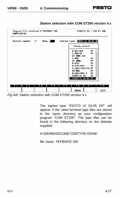
Station selection with COM ET200 version 4.x
The station type "FESTO VI 03-05 DP" willappear, if the valve terminal type files are storedin the same directory as your configurationprogram "COM ET200". The type files can befound in the following directory on the diskettesupplied:
A:\SIEMENS\COMET200\TYPE-03\GB\
file name: FEFB09TE.200
Fig.4/8: Station selection with COM ET200 version 4.x
VIFB9 - 03/05 4. Commissioning
9707 4-27
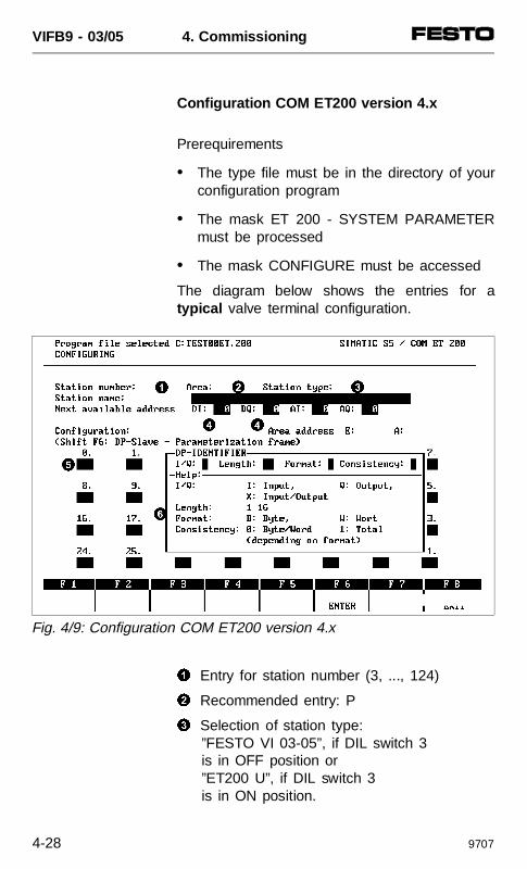
Configuration COM ET200 version 4.x
Prerequirements
• The type file must be in the directory of yourconfiguration program
• The mask ET 200 - SYSTEM PARAMETERmust be processed
• The mask CONFIGURE must be accessed
The diagram below shows the entries for atypical valve terminal configuration.
1 Entry for station number (3, ..., 124)
2 Recommended entry: P
3 Selection of station type:”FESTO VI 03-05”, if DIL switch 3is in OFF position or”ET200 U”, if DIL switch 3is in ON position.
1 2 3
4 4
5
6
Fig. 4/9: Configuration COM ET200 version 4.x
VIFB9 - 03/05 4. Commissioning
4-28 9707
4 Select the I/O start addresses, e.g.: DI = 24, DO = 24.
5 Configuration ( = equipment on valve termi-nal) Enter:• for each group of 8 inputs: 8DI • for each group of 8 outputs: 8DO
The entry fields must be assigned in as-cending order without gaps. No field maybe unused. Inputs must be entered beforeoutputs.
Example 1:Valve terminal with 4 x 8-input modules, + 12 single solenoid valves. Configuration:8DI, 8DI, 8DI, 8DI, 8DI, 8DO, 8DO
The 4 status bits increase the number of in-puts to 32 in this case (24I + 4I unused + 4 status bits).
Example 2: Valve terminal with 10 single solenoidvalves and 6 double solenoid valves.Configuration:8DO, 8DO, 8DO
VIFB9 - 03/05 4. Commissioning
9707 4-29
Alternatively, the complete number of inputs(including the 4 status bits) as well as thecomplete number of outputs can be entered asthe sum identifier.
PLEASE NOTEThe sum identifier may only be entered in con-junction with the setting ”DP standard.”
6 Use the help mask "DP identifier" to enterthe sum identifier. This mask can be accessed with: <F7> HELP. Select theformat "Byte" for the inputs and outputs. The format "Word" is not permitted.
ExampleValve terminal with 3 input modules,16 valve coils.1. DP identifier 019 for24I + 4I unused + 4 status bits.2. DP identifier 033 forcoils 1-16.
This completes the address assignment withCOM ET 200 V4.x.
VIFB9 - 03/05 4. Commissioning
4-30 9707
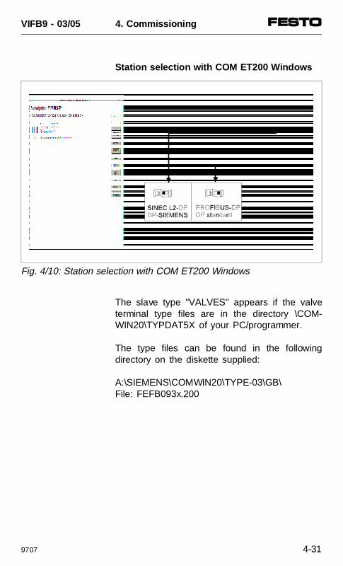
Station selection with COM ET200 Windows
The slave type "VALVES" appears if the valveterminal type files are in the directory \COM-WIN20\TYPDAT5X of your PC/programmer.
The type files can be found in the followingdirectory on the diskette supplied:
A:\SIEMENS\COMWIN20\TYPE-03\GB\File: FEFB093x.200
Fig. 4/10: Station selection with COM ET200 Windows
VIFB9 - 03/05 4. Commissioning
9707 4-31
Icons
In order to make configuration easy for you, thediskette contains files with valve terminal icons indirectory:
A:\SIEMENS\COMWIN20\TYPE-03\BMP\File: FE-TYP3N.200 and
FE-TYP3S.200
The icon appears, if the icon files are in thefollowing directory on your programmer/PC:\COMWIN20\BITMAPS\
PLEASE NOTEUpdate the slave catalogue when you copythe type files whilst processing the COMET200. Menu: ”File” - ”Read type files.”
VIFB9 - 03/05 4. Commissioning
4-32 9707
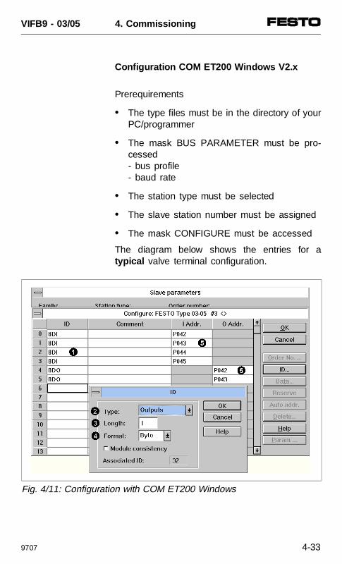
Configuration COM ET200 Windows V2.x
Prerequirements
• The type files must be in the directory of yourPC/programmer
• The mask BUS PARAMETER must be pro-cessed- bus profile- baud rate
• The station type must be selected
• The slave station number must be assigned
• The mask CONFIGURE must be accessed
The diagram below shows the entries for atypical valve terminal configuration.
1
2
3
4
5
5
Fig. 4/11: Configuration with COM ET200 Windows
VIFB9 - 03/05 4. Commissioning
9707 4-33
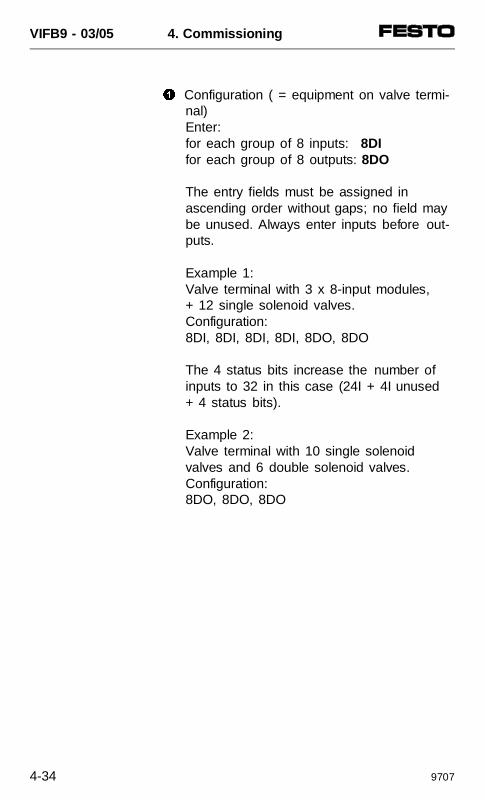
1 Configuration ( = equipment on valve termi-nal) Enter:for each group of 8 inputs: 8DI for each group of 8 outputs: 8DO
The entry fields must be assigned in ascending order without gaps; no field maybe unused. Always enter inputs before out-puts.
Example 1:Valve terminal with 3 x 8-input modules, + 12 single solenoid valves. Configuration:8DI, 8DI, 8DI, 8DI, 8DO, 8DO
The 4 status bits increase the number of inputs to 32 in this case (24I + 4I unused+ 4 status bits).
Example 2:Valve terminal with 10 single solenoidvalves and 6 double solenoid valves.Configuration:8DO, 8DO, 8DO
VIFB9 - 03/05 4. Commissioning
4-34 9707
Alternatively, the complete number of inputs(including the 4 status bits) as well as thecomplete number of outputs can be entered asthe sum identifier.
PLEASE NOTEThe sum identifier may only be entered in con-junction with the setting ”DP standard.”
The DP identifiers (individual identifiers or sumidentifiers) can also be entered in the window”Identifier ...”.
2 Type: Select inputs or outputs.
PLEASE NOTE The I/O types ”Input/output”, ”Empty space”etc. are not permitted.
3 Length: Enter 1 for 8 inputs or 8 outputs.Alternatively you can enter the sum of theinputs or outputs in bytes (gives sum identi-fier).
PLEASE NOTEAdd the 4 status bits to the number of inputs.
4 Format: Select ”Byte” for the configuration ofthe inputs and outputs. The setting ”Word”is not permitted.
VIFB9 - 03/05 4. Commissioning
9707 4-35
5 Input address/output address: Enter the startaddresses of the inputs and outputs.
Example:Valve terminal with 3 x 8 input modules,16 valve coils
1. DP identifier 8DI for 1st. 8-input module2. DP identifier 8DI for 2nd. 8-input module3. DP identifier 8DI for 3rd. 8-input module4. DP identifier 8DI for 4I reserves
+ 4 status bits5. DP identifier 8DO for coils 1-86. DP identifier 8DO for coils 9-16
This completes the configuration/addressassignment with COM ET 200 Windows.
VIFB9 - 03/05 4. Commissioning
4-36 9707
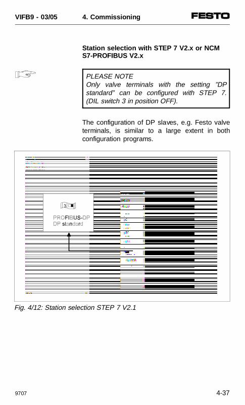
Station selection with STEP 7 V2.x or NCMS7-PROFIBUS V2.x
PLEASE NOTEOnly valve terminals with the setting ”DPstandard” can be configured with STEP 7.(DIL switch 3 in position OFF).
The configuration of DP slaves, e.g. Festo valveterminals, is similar to a large extent in bothconfiguration programs.
Fig. 4/12: Station selection STEP 7 V2.1
VIFB9 - 03/05 4. Commissioning
9707 4-37
The directory ”VALVES” appears if the type fileexists in the directory ”TYPEFILE” in the hard-ware catalogue.The type file can be found on the encloseddiskette in the file:A:\SIEMENS\COMWIN20\TYPE-03\GB\File: FEFB093E.200
The directory can be found in:”STEP_V2” and ”S7DATA”.
PLEASE NOTEUpdate the hardware catalogue after copyingthe type files.Menu sequence: ”extras” - ”Update DP typefiles”.
VIFB9 - 03/05 4. Commissioning
4-38 9707
Configuration with STEP 7 V2.x or NCM S7-PROFIBUS V2.x
Prerequirements
• The type file must be in the appropriatedirectory of your programmer/PC.
• The menu ”Configure hardware” must beaccessed.
• The DP master must be active in the rack.
• The mask ”Characteristics - DP master” mustbe processed.Menu sequence: ”Process” - ”Object charac-teristics” - ”SINEC L2”.
• The master system must be opened in therack. Either CPU with integrated DP interfaceor CP processor.Menu sequence: ”Process” - ”Master system” - ”Open”.
Carry out the following steps in order to add avalve terminal to the DP master and in order toconfigure it. The following diagrams show entriesof a typical valve terminal configuration.
VIFB9 - 03/05 4. Commissioning
9707 4-39
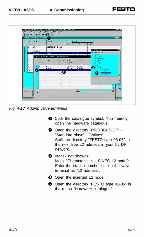
1 Click the catalogue symbol. You therebyopen the hardware catalogue.
2 Open the directory ”PROFIBUS-DP” - ”Standard slave” - ”Valves”.Shift the directory ”FESTO type 03-05” tothe next free L2 address in your L2-DP network.
3 <Mask not shown>Mask ”Characteristics - SINEC L2 node”:Enter the station number set on the valveterminal as ”L2 address”.
4 Open the inserted L2 node.
5 Open the directory ”FESTO type 03-05” inthe menu ”Hardware catalogue”.
1
2
54
6
Fig. 4/13: Adding valve terminals
VIFB9 - 03/05 4. Commissioning
4-40 9707
6 Integrate the contents of the directory(= standard module) into the first free loca-tion.
PLEASE NOTEAssign the locations in ascending order with-out gaps.
VIFB9 - 03/05 4. Commissioning
9707 4-41
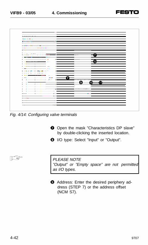
7 Open the mask ”Characteristics DP slave”by double-clicking the inserted location.
8 I/O type: Select ”Input” or ”Output”.
PLEASE NOTE”Output” or ”Empty space” are not permittedas I/O types.
9 Address: Enter the desired periphery ad-dress (STEP 7) or the address offset(NCM S7).
7
0 !
79
8
Fig. 4/14: Configuring valve terminals
VIFB9 - 03/05 4. Commissioning
4-42 9707
0 Length: Enter ”1” for 8 inputs or 8 outputs.Alternatively you can enter the sum of theinputs or outputs in bytes (sum identifier).
PLEASE NOTEAdd the four status bits to the number of inputs.
! Unit: Select ”Byte” for inputs or outputs.
This completes the configuration/address assign-ment with STEP 7 V2.x or NCM S7-PROFIBUS V2.x.
VIFB9 - 03/05 4. Commissioning
9707 4-43
Configuration with NCM S7-L2 V1.1
The configuration program NCM S7-L2 V1.1 isthe predecessor version of the NCM S7-PROFIBUS.
Configuration is made via the device master file(GSD).
The device master file can be found on theenclosed diskette in the directory:
A:\SIEMENS\NCM-S7.V11\GB\File: S03FB09E.GSD
For further information on configuring pleaserefer to the manual for your configurationprogram.
VIFB9 - 03/05 4. Commissioning
4-44 9707
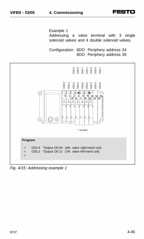
Example 1 Addressing a valve terminal with 3 singlesolenoid valves and 4 double solenoid valves.
Configuration: 8DO Periphery address 348DO Periphery address 35
0 1 23
45
67 9
811 13* 15
142101
Program :: = O34.4 "Output O0.04 (4th. valve right-hand coil): = O35.3 "Output O0.11 (7th. valve left-hand coil): =
O34
.0
* unused
O34
.1
O3
4.2
O34
.3
O3
4.4
O34
.5
O3
4.6
O34
.7
O3
5.0
O35
.1
O3
5.2
O35
.3
O3
5.4
O35
.5
O3
5.6
O35
.7
Fig. 4/15: Addressing example 1
VIFB9 - 03/05 4. Commissioning
9707 4-45
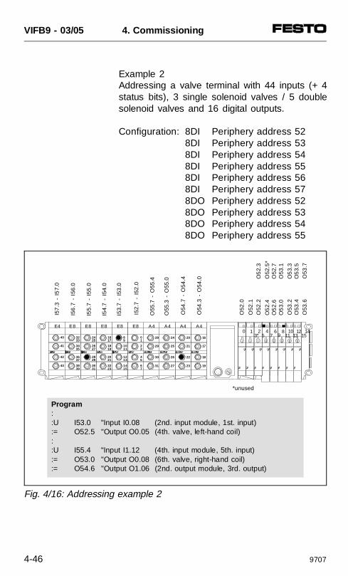
Example 2 Addressing a valve terminal with 44 inputs (+ 4status bits), 3 single solenoid valves / 5 doublesolenoid valves and 16 digital outputs.
Configuration: 8DI Periphery address 528DI Periphery address 538DI Periphery address 548DI Periphery address 558DI Periphery address 568DI Periphery address 578DO Periphery address 528DO Periphery address 538DO Periphery address 548DO Periphery address 55
0 1 23
45
67 9
811
10 1213*
141516
17
18
19
A4
20
21
22
23
A4
24
25
26
27
A4
28
29
30
31
A4
98
1110
1312
1514
E8
10
32
54
76
E8
1716
1918
2120
2322
E8
2524
2726
2928
3130
E8
3332
3534
3736
3938
E8E4
40
41
42
43
Program ::U I53.0 "Input I0.08 (2nd. input module, 1st. input):= O52.5 "Output O0.05 (4th. valve, left-hand coil): :U I55.4 "Input I1.12 (4th. input module, 5th. input):= O53.0 "Output O0.08 (6th. valve, right-hand coil):= O54.6 "Output O1.06 (2nd. output module, 3rd. output)
*unused
I57.
3 -
I57.
0
I56
.7 -
I56
.0
I55.
7 -
I55.
0
I54.
7 -
I54.
0
I53.
7 -
I53
.0
I52.
7 -
I52
.0
O55
.7 -
O55
.4
O54
.7 -
O54
.4
O55
.3 -
O55
.0
O54
.3 -
O54
.0
O52
.0
O5
2.4
O52
.5*
O5
2.6
O52
.7O
53.
0O
53.1
O52
.1O
52.2
O5
2.3
O53
.6O
53.7
O53
.2O
53.
3O
53.4
O5
3.5
Fig. 4/16: Addressing example 2
VIFB9 - 03/05 4. Commissioning
4-46 9707
4.3 GENERAL DP-MASTER
PLEASE NOTESet element 3 on the dip switch to "DP-stand-ard" (=OFF), in order to control the Festovalve terminal with a PROFIBUS-DP master.
The Festo valve terminal of types 03-05 can becontrolled by any PLC, PC or industrial PC witha PROFIBUS-DP module as per EN 50170 (DIN 19245).
Status bits
The valve terminal always makes 4 status bits(= inputs) available for diagnostic purposes, if thevalve terminal is fitted with at least one inputmodule (4 or 8-inputs).
PLEASE NOTE• The 4 status bits always increase the
number of inputs to be configured by 4.• Valve terminals without inputs do not have
any status bits.
Please refer to chapter 5 ”Diagnostics/errortreatment” for the function and position of thestatus bits.
VIFB9 - 03/05 4. Commissioning
9609 4-47
FREEZE and SYNC
The I/O processing commands FREEZE andSYNC are not supported by the valve terminal.In conjunction with the valve terminal, thecommands FREEZE and SYNC produce errormessages.
Module consistency
The valve terminal supports the following variants in module consistency:
• over the complete length of the valve terminal• over the selected format (byte/word).
Sequence of configuration entries
CAUTIONYou must always configure inputs beforeoutputs . The number of inputs/outputs (rounded up tofull bytes) must correspond to the equipmentfitted on the terminal. No additional inputs oroutputs may be configured as reserves.
VIFB9 - 03/05 4. Commissioning
4-48 9609
Bus start
Before the valve terminal can be commissionedcorrectly, the DP-master must perform thefollowing functions in this sequence.
1. Send a parametrizing telegram
2. Send a configuration telegram
3. Fetch diagnostic information
4. Start useful cyclic data transmission
The structure and content of the individualtelegrams are described in the following chap-ters.
VIFB9 - 03/05 4. Commissioning
9609 4-49
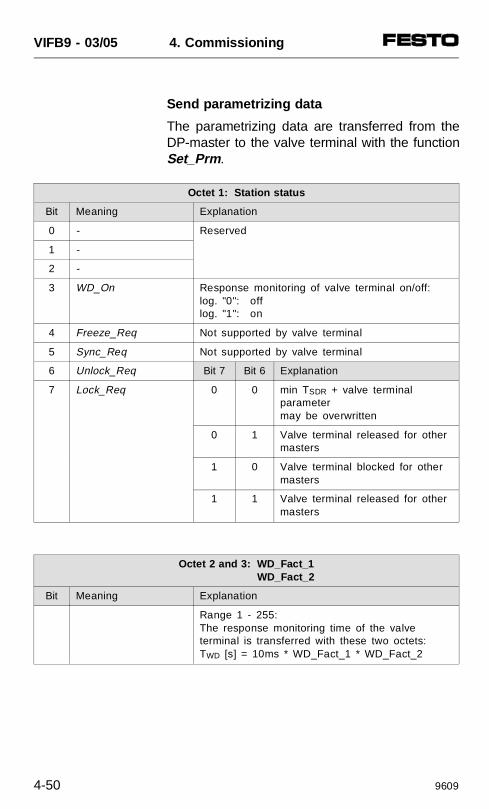
Send parametrizing data
The parametrizing data are transferred from theDP-master to the valve terminal with the functionSet_Prm .
Octet 1: Station status
Bit Meaning Explanation
0 - Reserved
1 -
2 -
3 WD_On Response monitoring of valve terminal on/off:log. "0": offlog. "1": on
4 Freeze_Req Not supported by valve terminal
5 Sync_Req Not supported by valve terminal
6 Unlock_Req Bit 7 Bit 6 Explanation
7 Lock_Req 0 0 min TSDR + valve terminalparametermay be overwritten
0 1 Valve terminal released for othermasters
1 0 Valve terminal blocked for othermasters
1 1 Valve terminal released for othermasters
Octet 2 and 3: WD_Fact_1 WD_Fact_2
Bit Meaning Explanation
Range 1 - 255:The response monitoring time of the valveterminal is transferred with these two octets:TWD [s] = 10ms * WD_Fact_1 * WD_Fact_2
VIFB9 - 03/05 4. Commissioning
4-50 9609
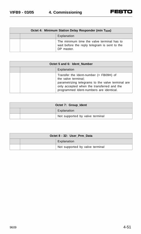
Octet 4: Minimum Station Delay Responder (min T SDR)
Explanation
The minimum time the valve terminal has to wait before the reply telegram is sent to theDP master.
Octet 5 and 6: Ident_Number
Explanation
Transfer the Ident-number (= FB09H) ofthe valve terminal;parametrizing telegrams to the valve terminal are only accepted when the transferred and the programmed Ident-numbers are identical.
Octet 7: Group_Ident
Explanation
Not supported by valve terminal
Octet 8 - 32: User_Prm_Data
Explanation
Not supported by valve terminal
VIFB9 - 03/05 4. Commissioning
9609 4-51
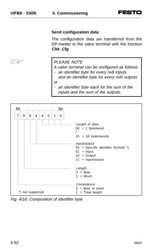
Send configuration data
The configuration data are transferred from theDP-master to the valve terminal with the functionChk_Cfg .
PLEASE NOTEA valve terminal can be configured as follows:- an identifier byte for every nx8 inputs
and an identifier byte for every nx8 outputsor- an identifier byte each for the sum of the
inputs and the sum of the outputs.
7 6 5 4 3 2 1 0
Bit Bit
Length of data00 = 1 byte/word*15 = 16 bytes/words
Input/output00 = Specific identifier formats *)01 = Input10 = Output11 = Input/output
Length0 = Byte1 = Word
Consistence0 = Byte or word1 = Total length*) not supported
Fig. 4/16: Composition of identifier byte
VIFB9 - 03/05 4. Commissioning
4-52 9609
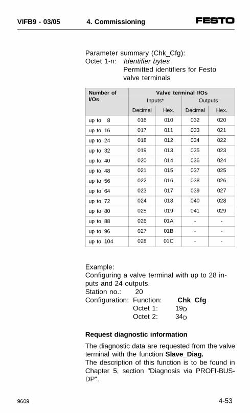
Parameter summary (Chk_Cfg):Octet 1-n: Identifier bytes
Permitted identifiers for Festo valve terminals
Example:Configuring a valve terminal with up to 28 in-puts and 24 outputs.Station no.: 20Configuration: Function: Chk_Cfg
Octet 1: 19D Octet 2: 34D
Request diagnostic information
The diagnostic data are requested from the valveterminal with the function Slave_Diag.The description of this function is to be found inChapter 5, section "Diagnosis via PROFI-BUS-DP".
Number ofI/Os
Valve terminal I/OsInputs* Outputs
Decimal Hex. Decimal Hex.
up to 8 016 010 032 020
up to 16 017 011 033 021
up to 24 018 012 034 022
up to 32 019 013 035 023
up to 40 020 014 036 024
up to 48 021 015 037 025
up to 56 022 016 038 026
up to 64 023 017 039 027
up to 72 024 018 040 028
up to 80 025 019 041 029
up to 88 026 01A - -
up to 96 027 01B - -
up to 104 028 01C - -
VIFB9 - 03/05 4. Commissioning
9609 4-53
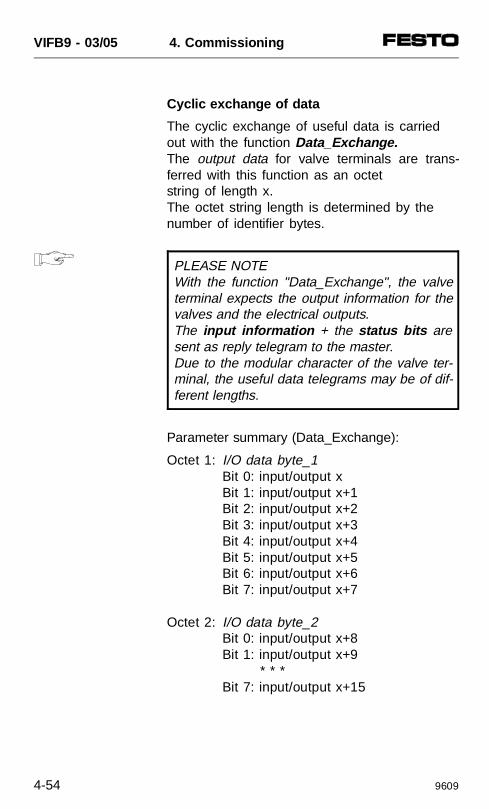
Cyclic exchange of data
The cyclic exchange of useful data is carried out with the function Data_Exchange. The output data for valve terminals are trans-ferred with this function as an octet string of length x.The octet string length is determined by the number of identifier bytes.
PLEASE NOTEWith the function "Data_Exchange", the valveterminal expects the output information for thevalves and the electrical outputs. The input information + the status bits aresent as reply telegram to the master.Due to the modular character of the valve ter-minal, the useful data telegrams may be of dif-ferent lengths.
Parameter summary (Data_Exchange):
Octet 1: I/O data byte_1Bit 0: input/output xBit 1: input/output x+1Bit 2: input/output x+2Bit 3: input/output x+3Bit 4: input/output x+4Bit 5: input/output x+5Bit 6: input/output x+6Bit 7: input/output x+7
Octet 2: I/O data byte_2Bit 0: input/output x+8Bit 1: input/output x+9
* * *Bit 7: input/output x+15
VIFB9 - 03/05 4. Commissioning
4-54 9609
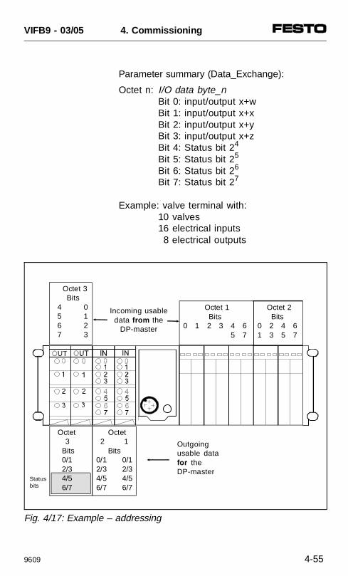
Parameter summary (Data_Exchange):
Octet n: I/O data byte_nBit 0: input/output x+wBit 1: input/output x+xBit 2: input/output x+yBit 3: input/output x+zBit 4: Status bit 24
Bit 5: Status bit 25
Bit 6: Status bit 26
Bit 7: Status bit 27
Example: valve terminal with:10 valves
16 electrical inputs 8 electrical outputs
Outgoingusable datafor theDP-master
Incoming usabledata from the
DP-master
Statusbits
Octet 1 Bits
0 1 2 3 4 6 5 7
Octet 2 Bits
0 2 4 61 3 5 7
Octet 3 Bits
4 0 5 1 6 2 7 3
Octet 2 1 Bits0/1 0/12/3 2/34/5 4/56/7 6/7
Octet 3 Bits 0/1 2/3 4/5 6/7
Fig. 4/17: Example – addressing
VIFB9 - 03/05 4. Commissioning
9609 4-55
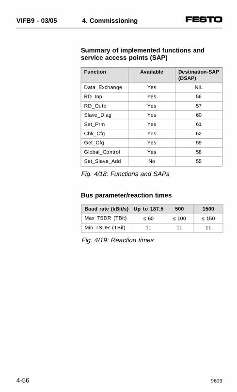
Summary of implemented functions and service access points (SAP)
Bus parameter/reaction times
Function Available Destination-SAP(DSAP)
Data_Exchange Yes NIL
RD_Inp Yes 56
RD_Outp Yes 57
Slave_Diag Yes 60
Set_Prm Yes 61
Chk_Cfg Yes 62
Get_Cfg Yes 59
Global_Control Yes 58
Set_Slave_Add No 55
Fig. 4/18: Functions and SAPs
Baud rate (kBit/s) Up to 187.5 500 1500
Max TSDR (TBit) ≤ 60 ≤ 100 ≤ 150
Min TSDR (TBit) 11 11 11
Fig. 4/19: Reaction times
VIFB9 - 03/05 4. Commissioning
4-56 9609
Device master file (GSD)
The diskette enclosed contains the device mas-ter file (GSD) with the specific standardizeddevice master specifications for the valve termi-nal.The standard device master file can be foundin directory:
A:\NORM-GSD\VI03FB09.GSD
Further information can be found in the file”Readme” on the diskette.
In addition to the slave-typical entries (Identnumber, revision, etc.), the device master filealso contains a selection of identifiers. Theseidentifiers can be divided into four main groups:
• digital inputs of the valve terminal (including 4status bits) and AS-i inputs.
• digital outputs of the valve terminal (pneuma-tic sub-bases and electrical outputs) and AS-ioutputs.
• analogue inputs• analogue outputs
VIFB9 - 03/05 4. Commissioning
9609 4-57
PLEASE NOTEYou can configure max. 6 identifiers. The indi-vidual identifiers must correspond to the exist-ing equipment fitted on the valve terminal.• Additional inputs/outputs as reserves are
not permitted.• If identifiers for certain components are not
used, you should enter the next following identifiers.
Enter the identifiers in the following sequence:
1. digital inputs of the valve terminal (incl. 4status bits)
2. digital outputs of the valve terminal (valvesand electrical outputs)
3. AS-i inputs
4. AS-i outputs
5. analogue inputs
6. analogue outputs
VIFB9 - 03/05 4. Commissioning
4-58 9609
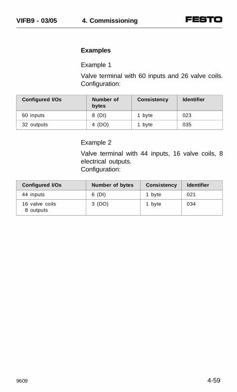
Examples
Example 1
Valve terminal with 60 inputs and 26 valve coils.Configuration:
Configured I/Os Number ofbytes
Consistency Identifier
60 inputs 8 (DI) 1 byte 023
32 outputs 4 (DO) 1 byte 035
Example 2
Valve terminal with 44 inputs, 16 valve coils, 8electrical outputs.Configuration:
Configured I/Os Number of bytes Consistency Identifier
44 inputs 6 (DI) 1 byte 021
16 valve coils 8 outputs
3 (DO) 1 byte 034
VIFB9 - 03/05 4. Commissioning
9609 4-59

VIFB9 - 03/05 4. Commissioning
4-60 9609
5. DIAGNOSIS AND
ERROR TREATMENT
VIFB9 - 03/05 5. Diagnosis/error treatement
9707 5-1
Contents
5.1 SUMMARY OFDIAGNOSTIC POSSIBILITIES 5-3
5.2 ON-THE-SPOT DIAGNOSIS 5-4LED displays 5-4Field bus node 5-4Valves 5-6Input/output modules 5-8
5.3 TESTING THE VALVES 5-9Starting/stopping the test routine 5-10
5.4 STATUS BITS 5-11Position of status bits 5-13
5.5 DIAGNOSIS VIA PROFIBUS-DP(DP-STANDARD) 5-15General 5-15Diagnostic words 5-15Summary of diagnostic bytes 5-17
5.6 DIAGNOSIS VIA SINEC L2-DP(DP-SIEMENS) 5-21General 5-21Summary of diagnostic bytes 5-21Diagnosis via programmer/PC 5-24
5.7 DIAGNOSIS VIA PROFIBUS-DP(GENERAL DP MASTER) 5-25General 5-25Diagnostic information 5-26
5.8 ERROR TREATMENT 5-30Reaction to faults in the control system 5-30 Siemens SIMATIC S5/S7 5-31 General DP master 5-31Short circuit / overload at an output module 5-32
VIFB9 - 03/05 5. Diagnosis/error treatement
5-2 9707
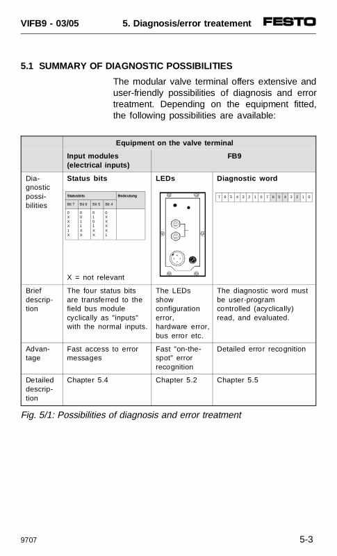
5.1 SUMMARY OF DIAGNOSTIC POSSIBILITIES
The modular valve terminal offers extensive anduser-friendly possibilities of diagnosis and errortreatment. Depending on the equipment fitted,the following possibilities are available:
Equipment on the valve terminal
Input modules(electrical inputs)
FB9
Dia-gnosticpossi-bilities
Status bits
X = not relevant
LEDs Diagnostic word
Brief descrip-tion
The four status bitsare transferred to thefield bus modulecyclically as "inputs"with the normal inputs.
The LEDsshowconfigurationerror,hardware error,bus error etc.
The diagnostic word mustbe user-programcontrolled (acyclically)read, and evaluated.
Advan-tage
Fast access to errormessages
Fast "on-the-spot" error recognition
Detailed error recognition
Detaileddescrip-tion
Chapter 5.4 Chapter 5.2 Chapter 5.5
Fig. 5/1: Possibilities of diagnosis and error treatment
Statusbits Bedeutung
Bit 7 Bit 6 Bit 5 Bit 4
0XXX1X
0011XX
0101XX
0XXXX1
7 6 5 4 3 2 1 0 7 6 5 4 3 2 1 0
VIFB9 - 03/05 5. Diagnosis/error treatement
9707 5-3
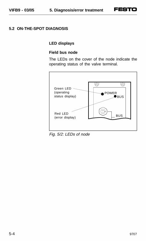
5.2 ON-THE-SPOT DIAGNOSIS
LED displays
Field bus node
The LEDs on the cover of the node indicate theoperating status of the valve terminal.
POWER
BUSRed LED (error display)
Green LED(operatingstatus display) BUS
Fig. 5/2: LEDs of node
VIFB9 - 03/05 5. Diagnosis/error treatment
5-4 9707
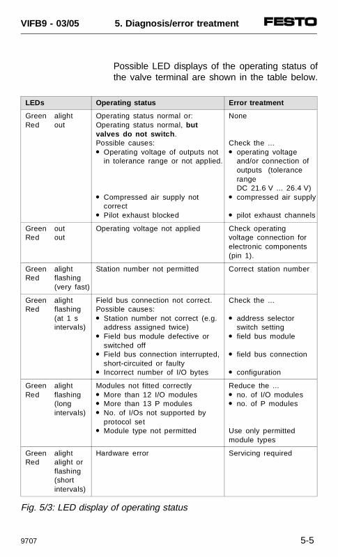
Possible LED displays of the operating status ofthe valve terminal are shown in the table below.
LEDs Operating status Error treatment
Green alightRed out
Operating status normal or:Operating status normal, but valves do not switch .Possible causes: Operating voltage of outputs not
in tolerance range or not applied.
Compressed air supply not correct
Pilot exhaust blocked
None
Check the ... operating voltage
and/or connection of outputs (tolerance range DC 21.6 V ... 26.4 V)
compressed air supply
pilot exhaust channels
Green outRed out
Operating voltage not applied Check operatingvoltage connection forelectronic components (pin 1).
Green alightRed flashing
(very fast)
Station number not permitted Correct station number
Green alightRed flashing
(at 1 sintervals)
Field bus connection not correct.Possible causes: Station number not correct (e.g.
address assigned twice) Field bus module defective or
switched off Field bus connection interrupted,
short-circuited or faulty Incorrect number of I/O bytes
Check the ...
address selectorswitch setting
field bus module
field bus connection
configuration
Green alightRed flashing
(long intervals)
Modules not fitted correctly More than 12 I/O modules More than 13 P modules No. of I/Os not supported by
protocol set Module type not permitted
Reduce the ... no. of I/O modules no. of P modules
Use only permittedmodule types
Green alightRed alight or
flashing(short intervals)
Hardware error Servicing required
Fig. 5/3: LED display of operating status
VIFB9 - 03/05 5. Diagnosis/error treatment
9707 5-5
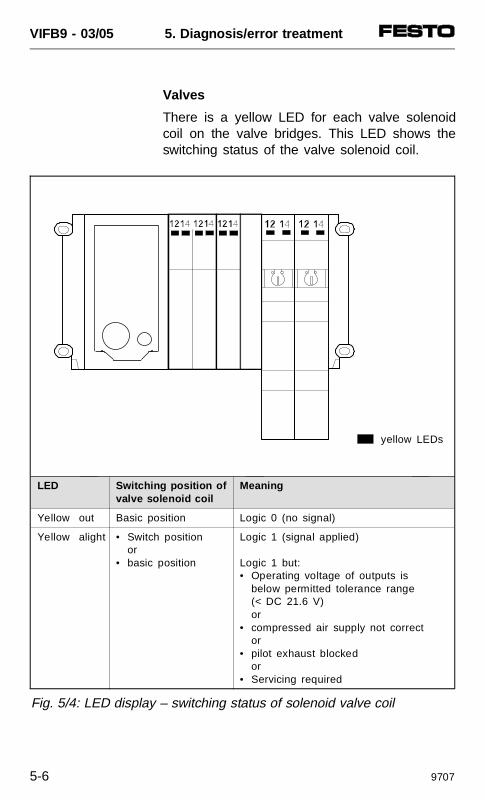
Valves
There is a yellow LED for each valve solenoidcoil on the valve bridges. This LED shows theswitching status of the valve solenoid coil.
LED Switching position ofvalve solenoid coil
Meaning
Yellow out Basic position Logic 0 (no signal)
Yellow alight • Switch positionor
• basic position
Logic 1 (signal applied)
Logic 1 but:• Operating voltage of outputs is
below permitted tolerance range (< DC 21.6 V) or
• compressed air supply not corrector
• pilot exhaust blocked or
• Servicing required
Fig. 5/4: LED display – switching status of solenoid valve coil
yellow LEDs
VIFB9 - 03/05 5. Diagnosis/error treatment
5-6 9707
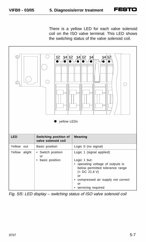
There is a yellow LED for each valve solenoidcoil on the ISO valve terminal. This LED showsthe switching status of the valve solenoid coil.
LED Switching position ofvalve solenoid coil
Meaning
Yellow out Basic position Logic 0 (no signal)
Yellow alight • Switch positionor
• basic position
Logic 1 (signal applied)
Logic 1 but:• operating voltage of outputs is
below permitted tolerance range (< DC 21.6 V) or
• compressed air supply not corrector
• servicing required
12 14 12 14 12 14 1214
yellow LEDs
Fig. 5/5: LED display – switching status of ISO valve solenoid coil
VIFB9 - 03/05 5. Diagnosis/error treatment
9707 5-7
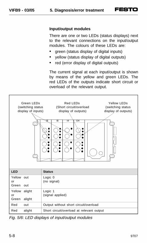
Input/output modules
There are one or two LEDs (status displays) nextto the relevant connections on the input/outputmodules. The colours of these LEDs are:
• green (status display of digital inputs)• yellow (status display of digital outputs)• red (error display of digital outputs)
The current signal at each input/output is shownby means of the yellow and green LEDs. Thered LEDs of the outputs indicate short circuit oroverload of the relevant output.
Red LEDs (Short circuit/overload
display of outputs)
Yellow LEDs(switching status
display of outputs)
Green LEDs(switching statusdisplay of inputs)
I8 I8 I4 O4
Fig. 5/6: LED displays of input/output modules
LED Status
Yellow outorGreen out
Logic 0(no signal)
Yellow alightorGreen alight
Logic 1(signal applied)
Red out Output without short circuit/overload
Red alight Short circuit/overload at relevant output
VIFB9 - 03/05 5. Diagnosis/error treatment
5-8 9707
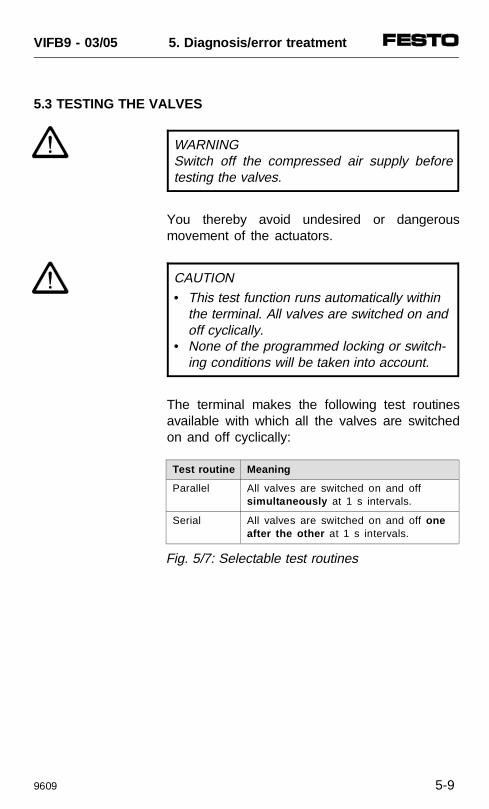
5.3 TESTING THE VALVES
WARNING Switch off the compressed air supply beforetesting the valves.
You thereby avoid undesired or dangerousmovement of the actuators.
CAUTION• This test function runs automatically within
the terminal. All valves are switched on andoff cyclically.
• None of the programmed locking or switch-ing conditions will be taken into account.
The terminal makes the following test routinesavailable with which all the valves are switchedon and off cyclically:
Test routine Meaning
Parallel All valves are switched on and offsimultaneously at 1 s intervals.
Serial All valves are switched on and off oneafter the other at 1 s intervals.
Fig. 5/7: Selectable test routines
VIFB9 - 03/05 5. Diagnosis/error treatment
9609 5-9
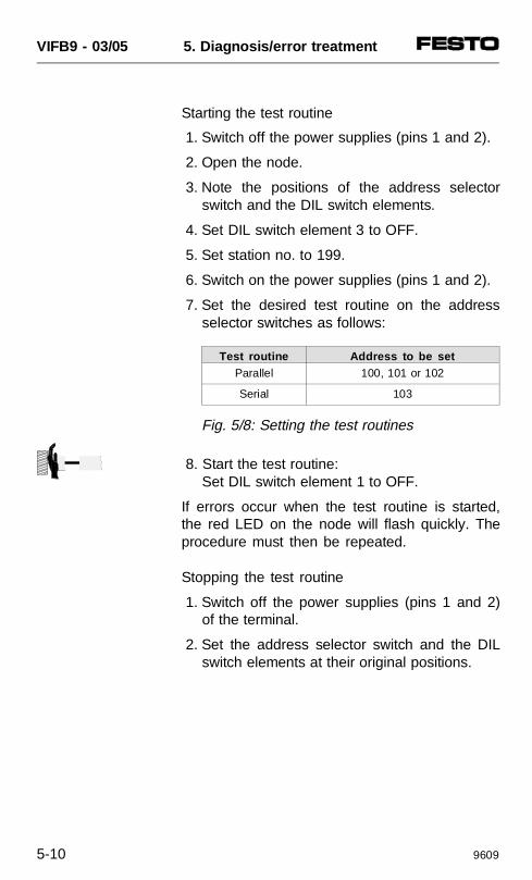
Starting the test routine
1. Switch off the power supplies (pins 1 and 2).
2. Open the node.
3. Note the positions of the address selectorswitch and the DIL switch elements.
4. Set DIL switch element 3 to OFF.
5. Set station no. to 199.
6. Switch on the power supplies (pins 1 and 2).
7. Set the desired test routine on the addressselector switches as follows:
8. Start the test routine:Set DIL switch element 1 to OFF.
If errors occur when the test routine is started,the red LED on the node will flash quickly. Theprocedure must then be repeated.
Stopping the test routine
1. Switch off the power supplies (pins 1 and 2)of the terminal.
2. Set the address selector switch and the DILswitch elements at their original positions.
Test routine Address to be setParallel 100, 101 or 102
Serial 103
Fig. 5/8: Setting the test routines
VIFB9 - 03/05 5. Diagnosis/error treatment
5-10 9609
5.4 STATUS BITS
Irrespective of the protocol/profile set, the valveterminal provides 4 status bits for diagnosis.
PLEASE NOTEThe four status bits of the valve terminal areonly available when the terminal is fitted withat least one input module.
The status bits are configured like inputs andalways occupy the four highest-value addressesof the available address range. The status bitsare made available at these addresses as soonas inputs are available. If the inputs of theaddresses thereunder are not used, the terminalwill be set at "logic zero".
VIFB9 - 03/05 5. Diagnosis/error treatment
9609 5-11
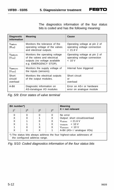
The diagnostics information of the four statusbits is coded and has the following meaning:
Diagnostic information
Meaning Cause
Vval ves
(Vval)Monitors the tolerance of theoperating voltage of the valvesand electrical outputs.
Operating voltage at pin 2 ofoperating voltage connection< 21.6 V
Vout puts
(Vout)Monitors the operating voltageof the valves and electricaloutputs (no voltage availablee.g. EMERGENCY STOP).
Operating voltage at pin 2 ofoperating voltage connection< 10 V
Vsen sors
(Vsen)Monitors the supply voltage ofthe inputs (sensors).
Internal fuse triggered
Short circuit/overload
Monitors the electrical outputsof the output modules.
Short circuit or overload
A-Bit Diagnostic information on AS-i/analogue I/O modules
Error on AS-i or hardwareerror on analogue module
Fig. 5/9: Error states of valve terminal
Bit number*) MeaningX = not relevant27 26 25 24
0XXX1X
0011XX
0101XX
0XXXX1
No errorOutput: short circuit/overloadVvalves < 21.6 VVoutputs < 10 VVsensors < 10 VA-Bit (AS-i / analogue I/Os)
*) The status bits always address the four highest-value addresses ofthe configured address range.
Fig. 5/10: Coded diagnostics information of the four status bits
VIFB9 - 03/05 5. Diagnosis/error treatment
5-12 9609
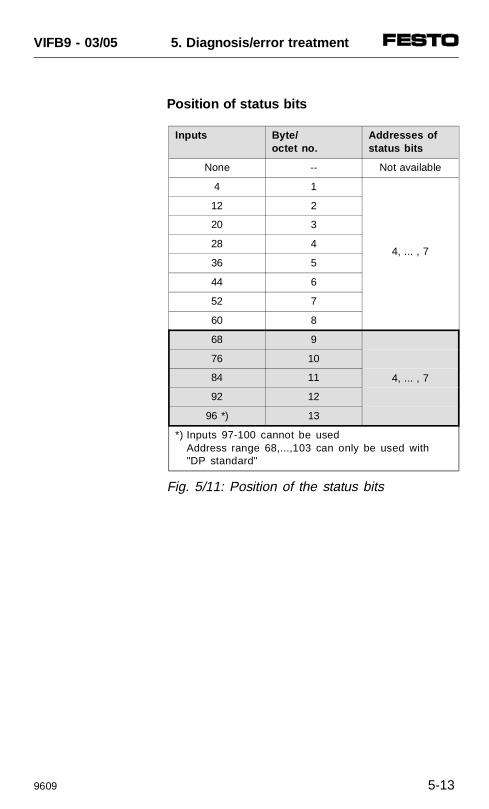
Position of status bits
Inputs Byte/ octet no.
Addresses ofstatus bits
None -- Not available
4 1
4, ... , 7
12 2
20 3
28 4
36 5
44 6
52 7
60 8
68 9
4, ... , 7
76 10
84 11
92 12
96 *) 13
*) Inputs 97-100 cannot be usedAddress range 68,...,103 can only be used with "DP standard"
Fig. 5/11: Position of the status bits
VIFB9 - 03/05 5. Diagnosis/error treatment
9609 5-13
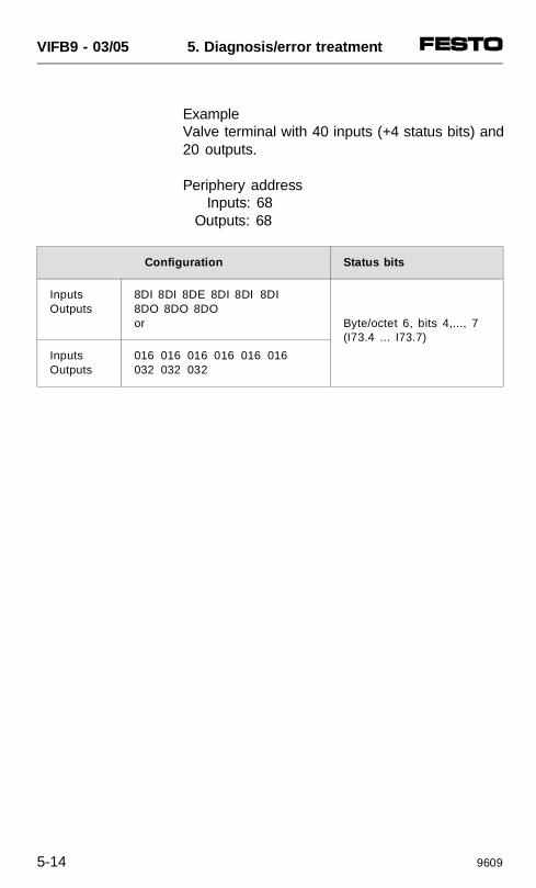
ExampleValve terminal with 40 inputs (+4 status bits) and20 outputs.
Periphery address Inputs: 68 Outputs: 68
Configuration Status bits
InputsOutputs
8DI 8DI 8DE 8DI 8DI 8DI8DO 8DO 8DOor Byte/octet 6, bits 4,..., 7
(I73.4 ... I73.7)
InputsOutputs
016 016 016 016 016 016032 032 032
VIFB9 - 03/05 5. Diagnosis/error treatment
5-14 9609
5.5 DIAGNOSIS VIA PROFIBUS-DP (DP-STANDARD)
General
PLEASE NOTEProtocol setting: "DP-standard". The "device-related diagnosis" as per EN 50170 is onlyavailable with this setting.
Diagnostic words
The diagnostic information of a valve terminal isgrouped together in diagnostic words.With these diagnostic words, the following errorstates are communicated to the terminal.
• operating voltage of the valves/outputs< 21.6 V (Vval)
• operating voltage of the valves/outputs< 10 V (Vout)
• operating voltage of the sensors < 10 V (Vsen)
• output overloaded/short circuited• AS-i error (bus, power and slave error)• error in analogue processing.
VIFB9 - 03/05 5. Diagnosis/error treatment
9707 5-15
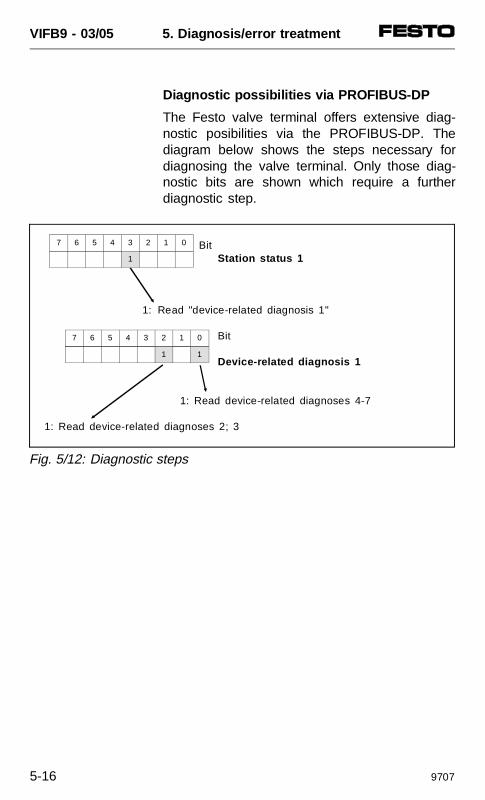
Diagnostic possibilities via PROFIBUS-DP
The Festo valve terminal offers extensive diag-nostic posibilities via the PROFIBUS-DP. Thediagram below shows the steps necessary fordiagnosing the valve terminal. Only those diag-nostic bits are shown which require a furtherdiagnostic step.
BitStation status 1
1: Read "device-related diagnosis 1"
Bit
Device-related diagnosis 1
1: Read device-related diagnoses 4-7
1: Read device-related diagnoses 2; 3
Fig. 5/12: Diagnostic steps
7 6 5 4 3 2 1 0
1
7 6 5 4 3 2 1 0
1 1
VIFB9 - 03/05 5. Diagnosis/error treatment
5-16 9707
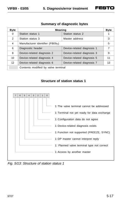
Summary of diagnostic bytes
Byte Meaning Byte0 Station status 1 Station status 2 1
2 Station status 3 Master address 3
4 Manufacturer identifier (FB09H) 5
6 Diagnostic header Device-related diagnosis 1 7
8 Device-related diagnosis 2 Device-related diagnosis 3 9
10 Device-related diagnosis 4 Device-related diagnosis 5 11
12 Device-related diagnosis 6 Device-related diagnosis 7 13
Contents modified by valve terminal
Structure of station status 1
1: The valve terminal cannot be addressed
1: Terminal not yet ready for data exchange
1: Configuration data do not agree
1: Device-related diagnosis exists
1: Function not supported (FREEZE, SYNC)
1: DP master cannot interpret reply
1: Planned valve terminal type not correct
1: Access by another master
Fig. 5/13: Structure of station status 1
7 6 5 4 3 2 1 0
VIFB9 - 03/05 5. Diagnosis/error treatment
9707 5-17
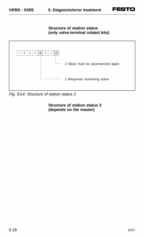
Structure of station status (only valve-terminal related bits)
Structure of station status 3 (depends on the master)
1: Slave must be parametrized again
1: Response monitoring active
Fig. 5/14: Structure of station status 2
7 6 5 4 3 2 1 0
VIFB9 - 03/05 5. Diagnosis/error treatment
5-18 9707
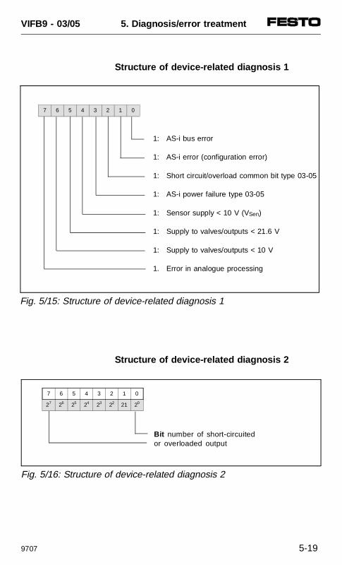
Structure of device-related diagnosis 1
Structure of device-related diagnosis 2
1: AS-i bus error
1: AS-i error (configuration error)
1: Short circuit/overload common bit type 03-05
1: AS-i power failure type 03-05
1: Sensor supply < 10 V (VSen)
1: Supply to valves/outputs < 21.6 V
1: Supply to valves/outputs < 10 V
1. Error in analogue processing
Fig. 5/15: Structure of device-related diagnosis 1
7 6 5 4 3 2 1 0
Bit number of short-circuitedor overloaded output
Fig. 5/16: Structure of device-related diagnosis 2
7 6 5 4 3 2 1 0
27 26 25 24 23 22 21 20
VIFB9 - 03/05 5. Diagnosis/error treatment
9707 5-19
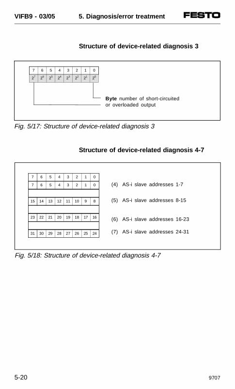
Structure of device-related diagnosis 3
Structure of device-related diagnosis 4-7
Byte number of short-circuitedor overloaded output
Fig. 5/17: Structure of device-related diagnosis 3
7 6 5 4 3 2 1 0
27 26 25 24 23 22 21 20
(4) AS-i slave addresses 1-7
(5) AS-i slave addresses 8-15
(6) AS-i slave addresses 16-23
(7) AS-i slave addresses 24-31
Fig. 5/18: Structure of device-related diagnosis 4-7
7 6 5 4 3 2 1 0
7 6 5 4 3 2 1 0
15 14 13 12 11 10 9 8
23 22 21 20 19 18 17 16
31 30 29 28 27 26 25 24
VIFB9 - 03/05 5. Diagnosis/error treatment
5-20 9707
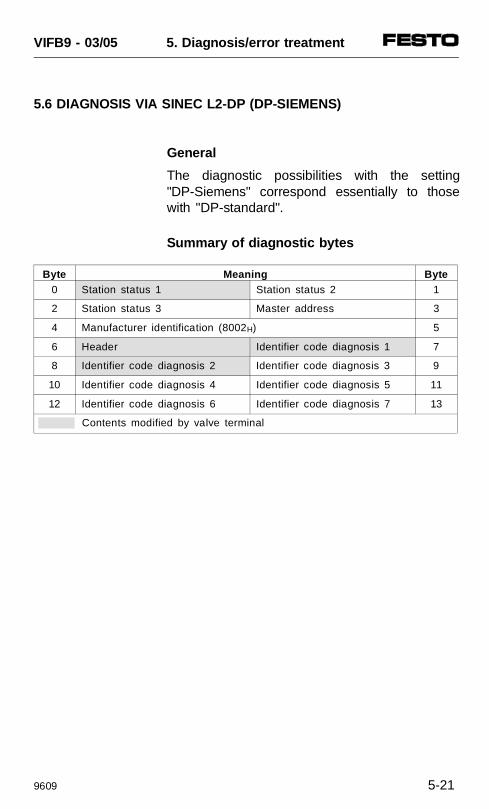
5.6 DIAGNOSIS VIA SINEC L2-DP (DP-SIEMENS)
General
The diagnostic possibilities with the setting"DP-Siemens" correspond essentially to thosewith "DP-standard".
Summary of diagnostic bytes
Byte Meaning Byte0 Station status 1 Station status 2 1
2 Station status 3 Master address 3
4 Manufacturer identification (8002H) 5
6 Header Identifier code diagnosis 1 7
8 Identifier code diagnosis 2 Identifier code diagnosis 3 9
10 Identifier code diagnosis 4 Identifier code diagnosis 5 11
12 Identifier code diagnosis 6 Identifier code diagnosis 7 13
Contents modified by valve terminal
VIFB9 - 03/05 5. Diagnosis/error treatment
9609 5-21
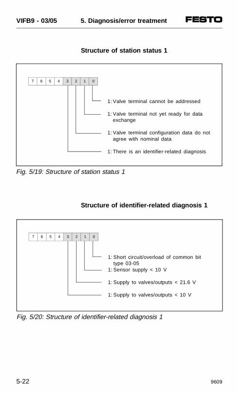
Structure of station status 1
Structure of identifier-related diagnosis 1
1: Valve terminal cannot be addressed
1: Valve terminal not yet ready for data exchange
1: Valve terminal configuration data do notagree with nominal data
1: There is an identifier-related diagnosis
Fig. 5/19: Structure of station status 1
7 6 5 4 3 2 1 0
1: Short circuit/overload of common bit type 03-05
1: Sensor supply < 10 V
1: Supply to valves/outputs < 21.6 V
1: Supply to valves/outputs < 10 V
Fig. 5/20: Structure of identifier-related diagnosis 1
7 6 5 4 3 2 1 0
VIFB9 - 03/05 5. Diagnosis/error treatment
5-22 9609
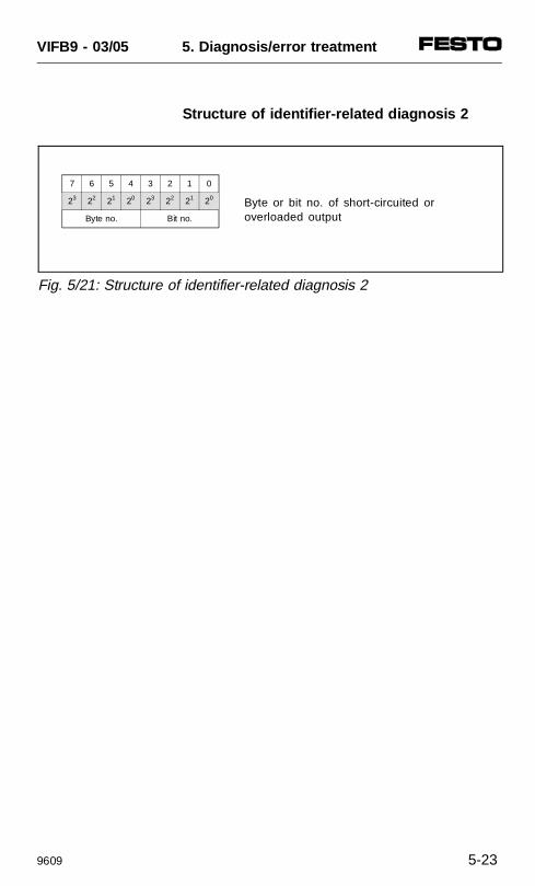
Structure of identifier-related diagnosis 2
Byte or bit no. of short-circuited or overloaded output
Fig. 5/21: Structure of identifier-related diagnosis 2
7 6 5 4 3 2 1 0
23 22 21 20 23 22 21 20
Byte no. Bit no.
VIFB9 - 03/05 5. Diagnosis/error treatment
9609 5-23
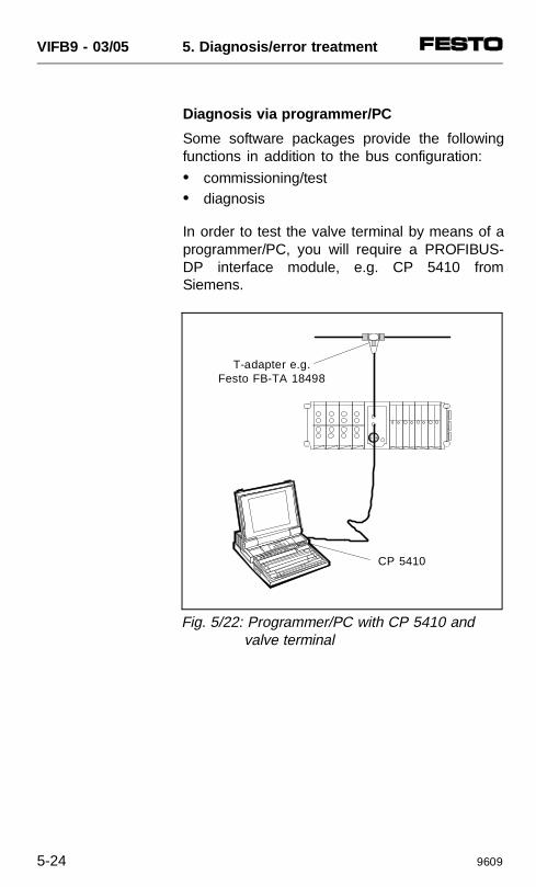
Diagnosis via programmer/PC
Some software packages provide the followingfunctions in addition to the bus configuration:
• commissioning/test• diagnosis
In order to test the valve terminal by means of aprogrammer/PC, you will require a PROFIBUS-DP interface module, e.g. CP 5410 fromSiemens.
T-adapter e.g.Festo FB-TA 18498
CP 5410
Fig. 5/22: Programmer/PC with CP 5410 and valve terminal
VIFB9 - 03/05 5. Diagnosis/error treatment
5-24 9609
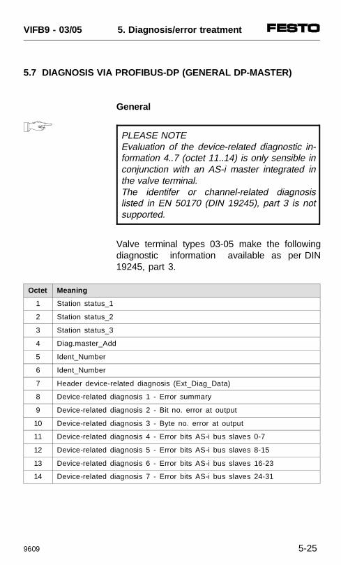
5.7 DIAGNOSIS VIA PROFIBUS-DP (GENERAL DP-MASTER)
General
PLEASE NOTEEvaluation of the device-related diagnostic in-formation 4..7 (octet 11..14) is only sensible inconjunction with an AS-i master integrated inthe valve terminal. The identifer or channel-related diagnosislisted in EN 50170 (DIN 19245), part 3 is notsupported.
Valve terminal types 03-05 make the followingdiagnostic information available as per DIN19245, part 3.
Octet Meaning
1 Station status_1
2 Station status_2
3 Station status_3
4 Diag.master_Add
5 Ident_Number
6 Ident_Number
7 Header device-related diagnosis (Ext_Diag_Data)
8 Device-related diagnosis 1 - Error summary
9 Device-related diagnosis 2 - Bit no. error at output
10 Device-related diagnosis 3 - Byte no. error at output
11 Device-related diagnosis 4 - Error bits AS-i bus slaves 0-7
12 Device-related diagnosis 5 - Error bits AS-i bus slaves 8-15
13 Device-related diagnosis 6 - Error bits AS-i bus slaves 16-23
14 Device-related diagnosis 7 - Error bits AS-i bus slaves 24-31
VIFB9 - 03/05 5. Diagnosis/error treatment
9609 5-25
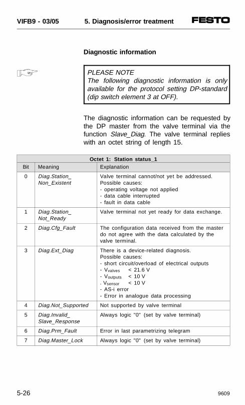
Diagnostic information
PLEASE NOTEThe following diagnostic information is onlyavailable for the protocol setting DP-standard(dip switch element 3 at OFF).
The diagnostic information can be requested bythe DP master from the valve terminal via thefunction Slave_Diag. The valve terminal replieswith an octet string of length 15.
Octet 1: Station status_1Bit Meaning Explanation
0 Diag.Station_Non_Existent
Valve terminal cannot/not yet be addressed.Possible causes:- operating voltage not applied- data cable interrupted- fault in data cable
1 Diag.Station_Not_Ready
Valve terminal not yet ready for data exchange.
2 Diag.Cfg_Fault The configuration data received from the masterdo not agree with the data calculated by thevalve terminal.
3 Diag.Ext_Diag There is a device-related diagnosis.Possible causes:- short circuit/overload of electrical outputs- Vvalves < 21.6 V- Voutputs < 10 V- Vsensor < 10 V- AS-i error- Error in analogue data processing
4 Diag.Not_Supported Not supported by valve terminal
5 Diag.Invalid_Slave_Response
Always logic "0" (set by valve terminal)
6 Diag.Prm_Fault Error in last parametrizing telegram
7 Diag.Master_Lock Always logic "0" (set by valve terminal)
VIFB9 - 03/05 5. Diagnosis/error treatment
5-26 9609
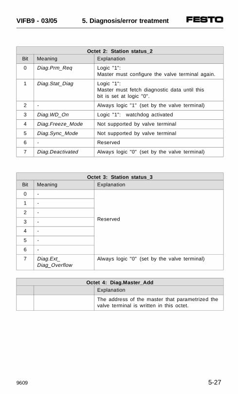
Octet 2: Station status_2Bit Meaning Explanation
0 Diag.Prm_Req Logic "1":Master must configure the valve terminal again.
1 Diag.Stat_Diag Logic "1":Master must fetch diagnostic data until this bit is set at logic "0".
2 - Always logic "1" (set by the valve terminal)
3 Diag.WD_On Logic "1": watchdog activated
4 Diag.Freeze_Mode Not supported by valve terminal
5 Diag.Sync_Mode Not supported by valve terminal
6 - Reserved
7 Diag.Deactivated Always logic "0" (set by the valve terminal)
Octet 3: Station status_3Bit Meaning Explanation
0 -
Reserved
1 -
2 -
3 -
4 -
5 -
6 -
7 Diag.Ext_Diag_Overflow
Always logic "0" (set by the valve terminal)
Octet 4: Diag.Master_AddExplanation
The address of the master that parametrized thevalve terminal is written in this octet.
VIFB9 - 03/05 5. Diagnosis/error treatment
9609 5-27
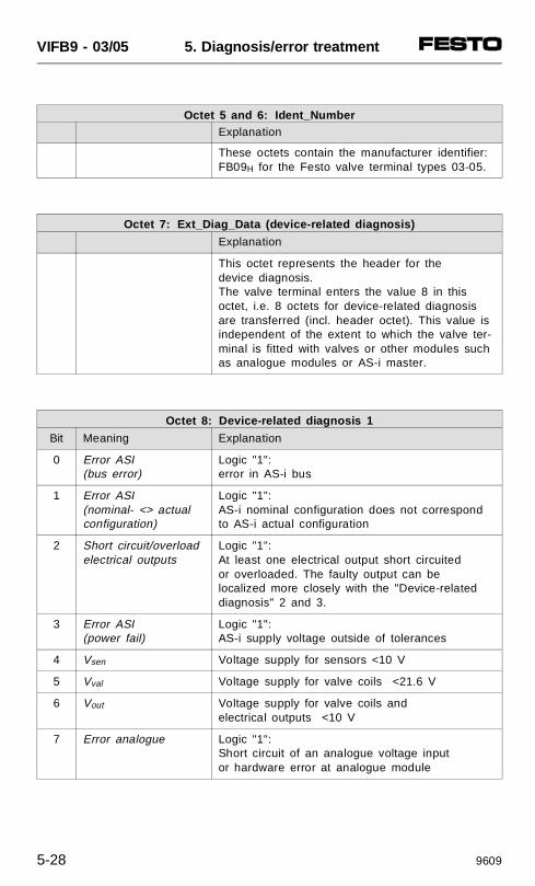
Octet 5 and 6: Ident_NumberExplanation
These octets contain the manufacturer identifier:FB09H for the Festo valve terminal types 03-05.
Octet 7: Ext_Diag_Data (device-related diagnosis)
Explanation
This octet represents the header for the device diagnosis.The valve terminal enters the value 8 in thisoctet, i.e. 8 octets for device-related diagnosisare transferred (incl. header octet). This value isindependent of the extent to which the valve ter-minal is fitted with valves or other modules suchas analogue modules or AS-i master.
Octet 8: Device-related diagnosis 1
Bit Meaning Explanation
0 Error ASI (bus error)
Logic "1":error in AS-i bus
1 Error ASI (nominal- <> actual configuration)
Logic "1":AS-i nominal configuration does not correspond to AS-i actual configuration
2 Short circuit/overloadelectrical outputs
Logic "1":At least one electrical output short circuited or overloaded. The faulty output can be localized more closely with the "Device-relateddiagnosis" 2 and 3.
3 Error ASI (power fail)
Logic "1":AS-i supply voltage outside of tolerances
4 Vsen Voltage supply for sensors <10 V
5 Vval Voltage supply for valve coils <21.6 V
6 Vout Voltage supply for valve coils and electrical outputs <10 V
7 Error analogue Logic "1":Short circuit of an analogue voltage input or hardware error at analogue module
VIFB9 - 03/05 5. Diagnosis/error treatment
5-28 9609
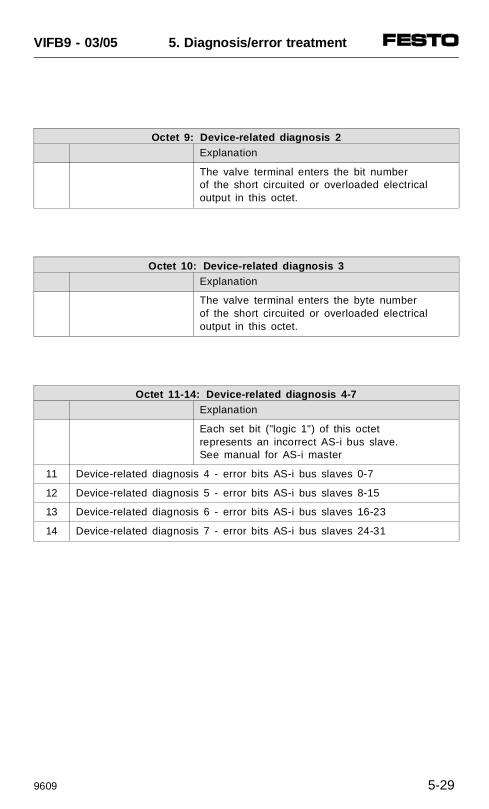
Octet 9: Device-related diagnosis 2Explanation
The valve terminal enters the bit number of the short circuited or overloaded electrical output in this octet.
Octet 10: Device-related diagnosis 3Explanation
The valve terminal enters the byte number of the short circuited or overloaded electrical output in this octet.
Octet 11-14: Device-related diagnosis 4-7Explanation
Each set bit ("logic 1") of this octet represents an incorrect AS-i bus slave. See manual for AS-i master
11 Device-related diagnosis 4 - error bits AS-i bus slaves 0-7
12 Device-related diagnosis 5 - error bits AS-i bus slaves 8-15
13 Device-related diagnosis 6 - error bits AS-i bus slaves 16-23
14 Device-related diagnosis 7 - error bits AS-i bus slaves 24-31
VIFB9 - 03/05 5. Diagnosis/error treatment
9609 5-29
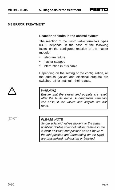
5.8 ERROR TREATMENT
Reaction to faults in the control system
The reaction of the Festo valve terminals types03-05 depends, in the case of the followingfaults, on the configured reaction of the mastermodule.
• telegram failure• master stopped• interruption in bus cable
Depending on the setting or the configuration, allthe outputs (valves and electrical outputs) areswitched off or maintain their status.
WARNINGEnsure that the valves and outputs are resetafter the faults name. A dangerous situationcan arise, if the valves and outputs are notreset.
PLEASE NOTESingle solenoid valves move into the basicposition; double solenoid valves remain in the current position; mid-position valves move tothe mid-position and (depending on the type)are pressurized, exhausted or blocked.
VIFB9 - 03/05 5. Diagnosis/error treatment
5-30 9609
Siemens SIMATIC S5/S7
With these controllers, you can determine thereaction of the valve terminal to the followingfaults:
• controller failure• bus interruption• program stop
Almost all configuration programs contain thefunction "response monitoring". For the operatingmodes named, the specified time represents thefailure time of the valves and electrical outputs.Please refer to the relevant manuals for furtherdetails on response monitoring.
General DP-master
By means of the function Set_Prm , you candetermine the watchdog time (WD_Fact_1, Octet2, WD_Fact_2, Octet 3). In the case of a fault,e.g. bus failure etc., the valve terminal switchesall valves and electrical outputs off after theparametrized time.
VIFB9 - 03/05 5. Diagnosis/error treatment
9609 5-31
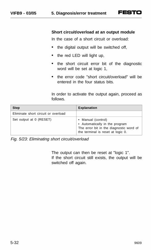
Short circuit/overload at an output module
In the case of a short circuit or overload:
• the digital output will be switched off,
• the red LED will light up,
• the short circuit error bit of the diagnosticword will be set at logic 1,
• the error code "short circuit/overload" will beentered in the four status bits.
In order to activate the output again, proceed asfollows.
The output can then be reset at "logic 1".If the short circuit still exists, the output will beswitched off again.
Step Explanation
Eliminate short circuit or overload
Set output at 0 (RESET) • Manual (control)• Automatically in the programThe error bit in the diagnostic word ofthe terminal is reset at logic 0.
Fig. 5/23: Eliminating short circuit/overload
VIFB9 - 03/05 5. Diagnosis/error treatment
5-32 9609
TECHNICAL APPENDIX
VIFB9 - 03/05 Appendix A
9609 A-1
Contents
TECHNICAL SPECIFICATIONS A-3General A-3Operating voltage for electronic components and inputs A-4
Operating voltage for outputs/valves A-4
Electric input modules A-5
Electric output modules A-5
Field bus A-6
Electromagnetic compatibilitiy (EMC) A-6
CABLE LENGTH AND CROSS SECTION A-7Calculating with graphics A-8Calculating with a formula A-10
EXAMPLES OF CIRCUITRY A-12Operating voltage connection type 03 A-12Operating voltage connection type 05 A-134-input module PNP A-148-input module PNP A-154-input-module NPN A-168-input module NPN A-174-output module A-18
VIFB9 - 03/05 Appendix A
A-2 9609
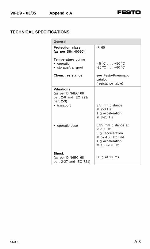
TECHNICAL SPECIFICATIONS
General
Protection class(as per DIN 40050)
Temperatur e during• operation• storage/transport
Chem. resistance
IP 65
- 5 oC . . . +50 oC-20 oC . . . +60 oC
see Festo-Pneumaticcatalog (resistance table)
Vibrations(as per DIN/IEC 68 part 2-6 and IEC 721/part 2-3)• transport
• operation/use
Shock(as per DIN/IEC 68 part 2-27 and IEC 721)
3.5 mm distance at 2-8 Hz1 g accelerationat 8-25 Hz
0.35 mm distance at 25-57 Hz5 g accelerationat 57-150 Hz und1 g accelerationat 150-200 Hz
30 g at 11 ms
VIFB9 - 03/05 Appendix A
9609 A-3
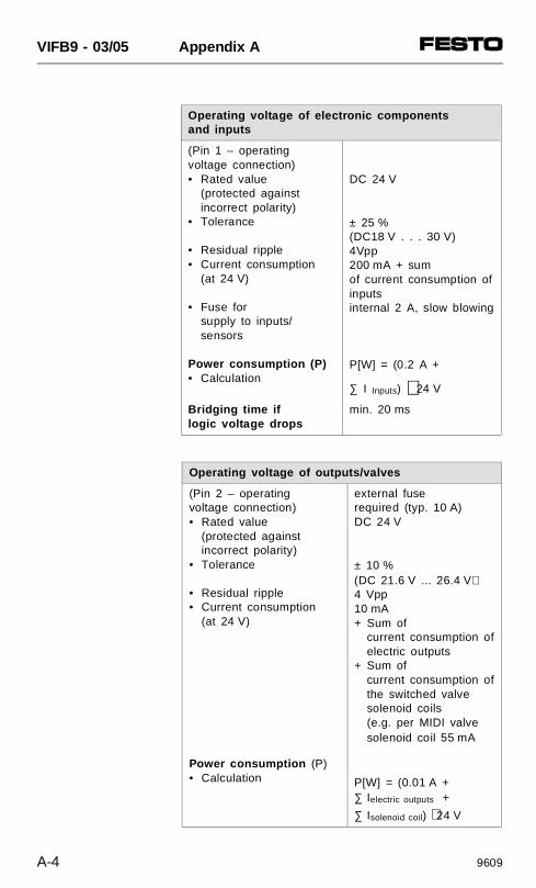
Operating voltage of electronic components and inputs
(Pin 1 – operating voltage connection)• Rated value
(protected against incorrect polarity)
• Tolerance
• Residual ripple• Current consumption
(at 24 V)
• Fuse for supply to inputs/sensors
Power consumption (P)• Calculation
DC 24 V
± 25 %(DC18 V . . . 30 V)4Vpp200 mA + sum of current consumption ofinputsinternal 2 A, slow blowing
P[W] = (0.2 A +
∑ I Inputs) ⋅ 24 V
Bridging time iflogic voltage drops
min. 20 ms
Operating voltage of outputs/valves
(Pin 2 – operatingvoltage connection)• Rated value
(protected against incorrect polarity)
• Tolerance
• Residual ripple• Current consumption
(at 24 V)
Power consumption (P)• Calculation
external fuse required (typ. 10 A)DC 24 V
± 10 %(DC 21.6 V ... 26.4 V)4 Vpp10 mA + Sum of
current consumption ofelectric outputs
+ Sum ofcurrent consumption ofthe switched valve solenoid coils (e.g. per MIDI valvesolenoid coil 55 mA
P[W] = (0.01 A +∑ Ielectric outputs +
∑ Isolenoid coil) ⋅ 24 V
VIFB9 - 03/05 Appendix A
A-4 9609
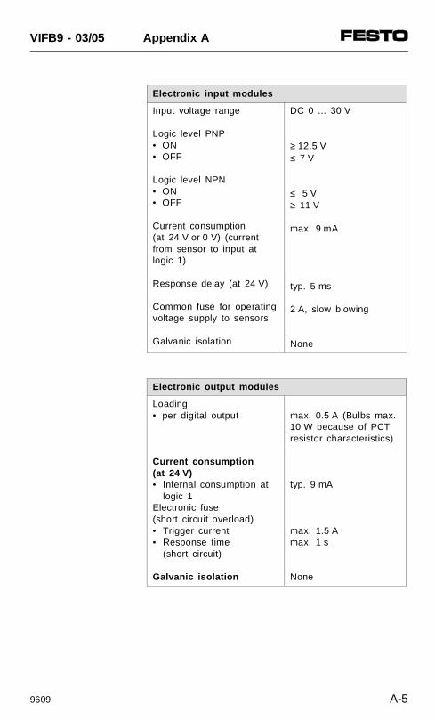
Electronic input modules
Input voltage range
Logic level PNP• ON• OFF
Logic level NPN• ON• OFF
Current consumption (at 24 V or 0 V) (currentfrom sensor to input atlogic 1)
Response delay (at 24 V)
Common fuse for operating voltage supply to sensors
Galvanic isolation
DC 0 ... 30 V
≥ 12.5 V≤ 7 V
≤ 5 V≥ 11 V
max. 9 mA
typ. 5 ms
2 A, slow blowing
None
Electronic output modules
Loading • per digital output
Current consumption (at 24 V)• Internal consumption at
logic 1Electronic fuse(short circuit overload)• Trigger current • Response time
(short circuit)
Galvanic isolation
max. 0.5 A (Bulbs max.10 W because of PCTresistor characteristics)
typ. 9 mA
max. 1.5 Amax. 1 s
None
VIFB9 - 03/05 Appendix A
9609 A-5
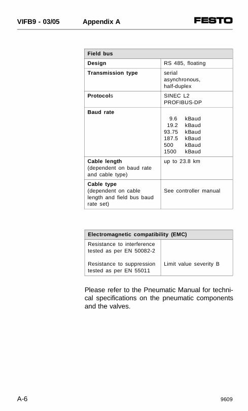
Please refer to the Pneumatic Manual for techni-cal specifications on the pneumatic componentsand the valves.
Field bus
Design RS 485, floating
Transmission type serialasynchronous,half-duplex
Protocol s SINEC L2PROFIBUS-DP
Baud rate 9.6 kBaud 19.2 kBaud93.75 kBaud187.5 kBaud500 kBaud1500 kBaud
Cable length(dependent on baud rateand cable type)
up to 23.8 km
Cable type(dependent on cablelength and field bus baudrate set)
See controller manual
Electromagnetic compatibility (EMC)
Resistance to interferencetested as per EN 50082-2
Resistance to suppression tested as per EN 55011
Limit value severity B
VIFB9 - 03/05 Appendix A
A-6 9609
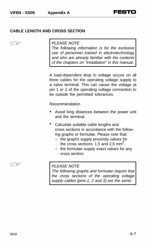
CABLE LENGTH AND CROSS SECTION
PLEASE NOTEThe following information is for the exclusiveuse of personnel trained in electrotechnologyand who are already familiar with the contentsof the chapters on "Installation" in this manual.
A load-dependent drop in voltage occurs on allthree cables for the operating voltage supply toa valve terminal. This can cause the voltage atpin 1 or 2 of the operating voltage connection tobe outside the permitted tolerances.
Recommendation
• Avoid long distances between the power unitand the terminal.
• Calculate suitable cable lengths and cross sections in accordance with the follow-ing graphs or formulae. Please note that:– the graphs supply proximity values for
the cross sections; 1.5 and 2.5 mm2.– the formulae supply exact values for any
cross section.
PLEASE NOTEThe following graphs and formulae require thatthe cross sections of the operating voltagesupply cables (pins 1, 2 and 3) are the same.
VIFB9 - 03/05 Appendix A
9609 A-7
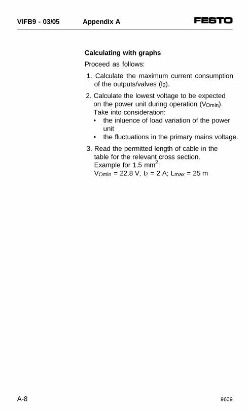
Calculating with graphs
Proceed as follows:
1. Calculate the maximum current consumptionof the outputs/valves (I2).
2. Calculate the lowest voltage to be expectedon the power unit during operation (VOmin).Take into consideration:• the inluence of load variation of the power
unit• the fluctuations in the primary mains voltage.
3. Read the permitted length of cable in thetable for the relevant cross section.Example for 1.5 mm2:VOmin = 22.8 V, I2 = 2 A; Lmax = 25 m
VIFB9 - 03/05 Appendix A
A-8 9609
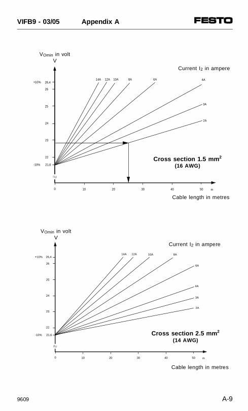
10A 6A 4A
21,6
10 20 30 40 50 m
+10%
-10%
26,4
2A
8A
3A
0
12A14A
22
23
24
25
26
VOmin in voltV
Current I2 in ampere
Cable length in metres
Cross section 1.5 mm 2
(16 AWG)
12A14A
21,6
22
23
24
25
26
10 20 30 40 50 m
+10%
-10%
26,4
0
10A 8A
6A
4A
3A
2A
VOmin in voltV
Current I2 in ampere
Cable length in metres
Cross section 2.5 mm 2
(14 AWG)
VIFB9 - 03/05 Appendix A
9609 A-9
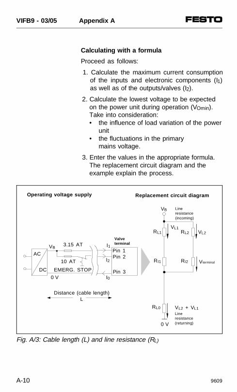
Calculating with a formula
Proceed as follows:
1. Calculate the maximum current consumptionof the inputs and electronic components (I1)as well as of the outputs/valves (I2).
2. Calculate the lowest voltage to be expectedon the power unit during operation (VOmin).Take into consideration:• the influence of load variation of the power
unit• the fluctuations in the primary
mains voltage.
3. Enter the values in the appropriate formula.The replacement circuit diagram and theexample explain the process.
AC
DC
0 V
VB
EMERG. STOP
3.15 AT
10 AT
I1
I2
Pin 1Pin 2
Pin 3
Valveterminal
RL0
0 V
VL2 + VL1
Vterminal
Lineresistance(incoming)
RI2RI1
VB
RL1
Line resistance(returning)
VL1VL2RL2
Distance (cable length)L
Operating voltage supply Replacement circuit diagram
I0
Fig. A/3: Cable length (L) and line resistance (RL)
VIFB9 - 03/05 Appendix A
A-10 9609
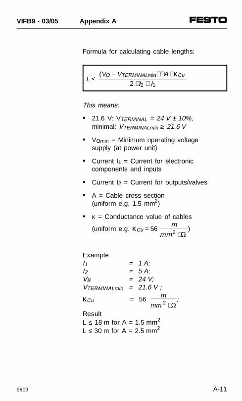
Formula for calculating cable lengths:
L ≤ (VO − VTERMINALmin) ⋅ A ⋅ κCu
2 ⋅ I2 + I1
This means:
• 21.6 V: VTERMINAL = 24 V ± 10%, minimal: VTERMINALmin ≥ 21.6 V
• VOmin = Minimum operating voltagesupply (at power unit)
• Current I1 = Current for electronic components and inputs
• Current I2 = Current for outputs/valves
• A = Cable cross section (uniform e.g. 1.5 mm2)
• κ = Conductance value of cables
(uniform e.g. κCu = 56 mmm 2 ⋅ Ω
)
Example I1 = 1 A; I2 = 5 A; VB = 24 V; VTERMINALmin = 21.6 V ;
κCu = 56 m
mm 2 ⋅ Ω;
ResultL ≤ 18 m for A = 1.5 mm2
L ≤ 30 m for A = 2.5 mm2
VIFB9 - 03/05 Appendix A
9609 A-11
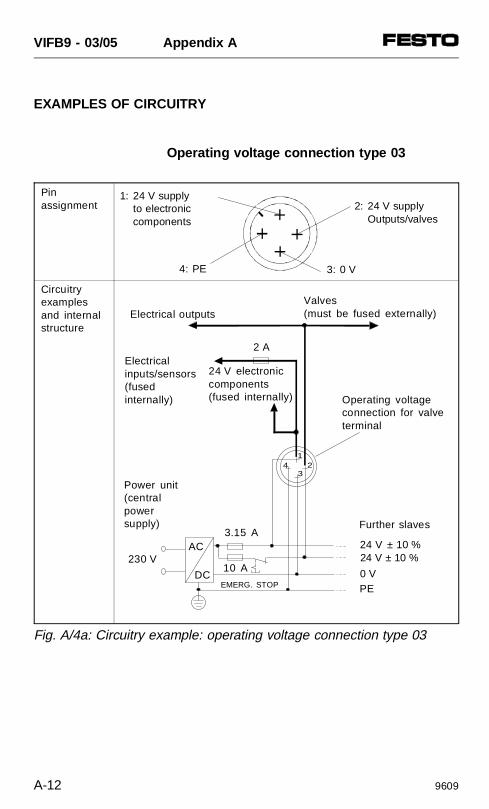
EXAMPLES OF CIRCUITRY
Operating voltage connection type 03
Pinassignment
Circuitryexamplesand internalstructure
Fig. A/4a: Circuitry example: operating voltage connection type 03
34 2
1
230 V
Power unit (central powersupply)
AC
DC
3.15 A
10 A
24 V ± 10 %24 V ± 10 %
0 VPE
Electricalinputs/sensors (fused internally)
Valves (must be fused externally)Electrical outputs
24 V electroniccomponents(fused internally)
2 A
Operating voltageconnection for valveterminal
EMERG. STOP
Further slaves
2: 24 V supplyOutputs/valves
3: 0 V4: PE
1: 24 V supplyto electronic components
VIFB9 - 03/05 Appendix A
A-12 9609
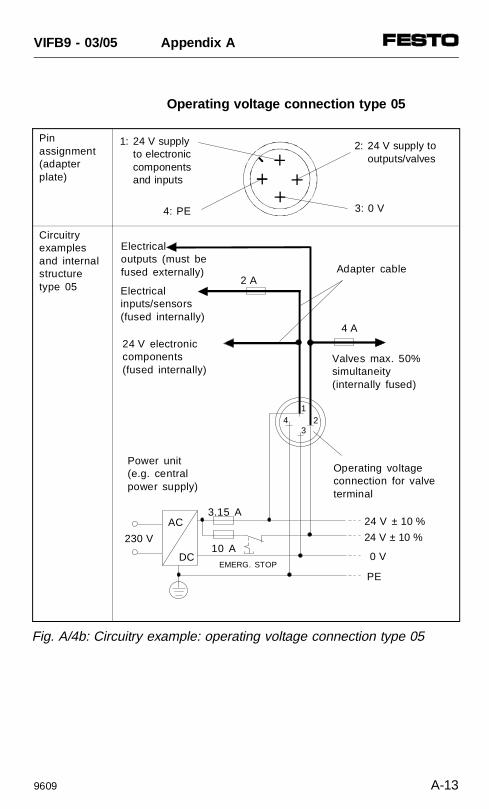
Operating voltage connection type 05
34 2
1
230 V
Power unit (e.g. central power supply)
AC
DC
3.15 A
10 A
24 V ± 10 %
24 V ± 10 %
0 V
PE
Electrical inputs/sensors (fused internally)
Adapter cable
Electrical outputs (must be fused externally)
24 V electroniccomponents(fused internally)
2 A
Operating voltageconnection for valveterminal
EMERG. STOP
4 A
Valves max. 50%simultaneity(internally fused)
Fig. A/4b: Circuitry example: operating voltage connection type 05
Pinassignment(adapterplate)
Circuitryexamplesand internalstructuretype 05
2: 24 V supply tooutputs/valves
3: 0 V4: PE
1: 24 V supplyto electronic components and inputs
VIFB9 - 03/05 Appendix A
9609 A-13
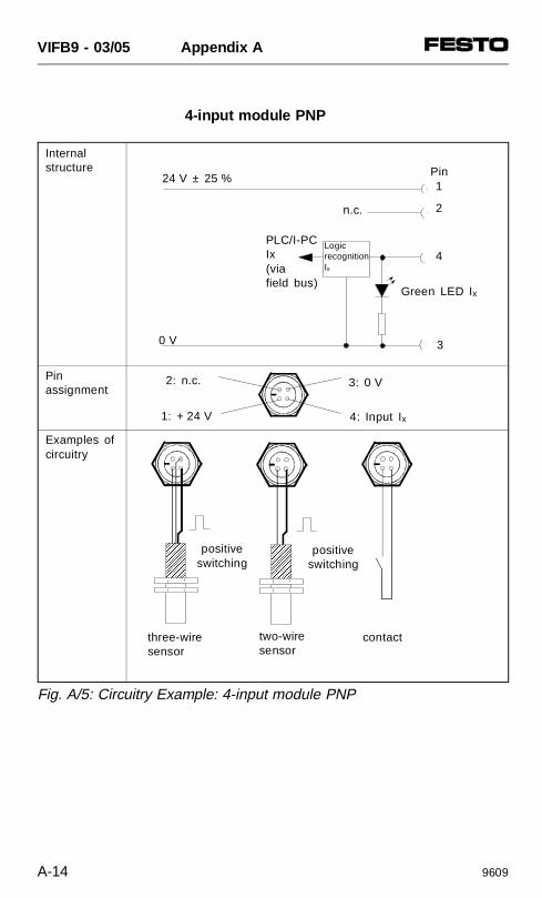
4-input module PNP
AAAAAAAAAAAAAAAAAAAAAAAAAAAAAAAA
AAAAAAAA
AAAAAAAAAAAAAAAAAAAAAAAAAAAAAAAApositive
switchingpositive
switching
Pin1
2
4
3
Logic recognitionIx
n.c.
PLC/I-PCIx(viafield bus)
24 V ± 25 %
0 V
3: 0 V
4: Input Ix
2: n.c.
1: + 24 V
Internal structure
Pinassignment
Examples ofcircuitry
Fig. A/5: Circuitry Example: 4-input module PNP
three-wire sensor
two-wiresensor
contact
Green LED Ix
VIFB9 - 03/05 Appendix A
A-14 9609
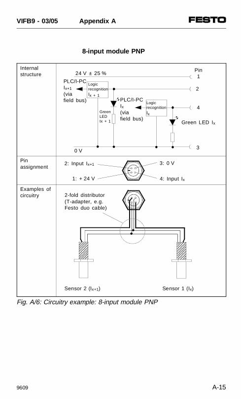
8-input module PNP
Internalstructure
Pinassignment
Examples ofcircuitry
Fig. A/6: Circuitry example: 8-input module PNP
Green LEDIx + 1
AAAAAAAAAAAAAAAAAAAAAAAAAAAAAAAA
AAAAAAAA
AAAAAAAAAAAAAAAAAAAAAAAAAAAAAAAA
AAAAAAAA
Sensor 2 (Ix+1) Sensor 1 (Ix)
Pin1
4
3
Logic recognitionIx
PLC/I-PCIx+1
(via field bus)
24 V ± 25 %
0 V
3: 0 V
4: Input Ix
2: Input Ix+1
1: + 24 V
2-fold distributor (T-adapter, e.g.Festo duo cable)
Logic recognitionIx + 1
PLC/I-PCIx(via field bus)
Green LED Ix
2
VIFB9 - 03/05 Appendix A
9609 A-15
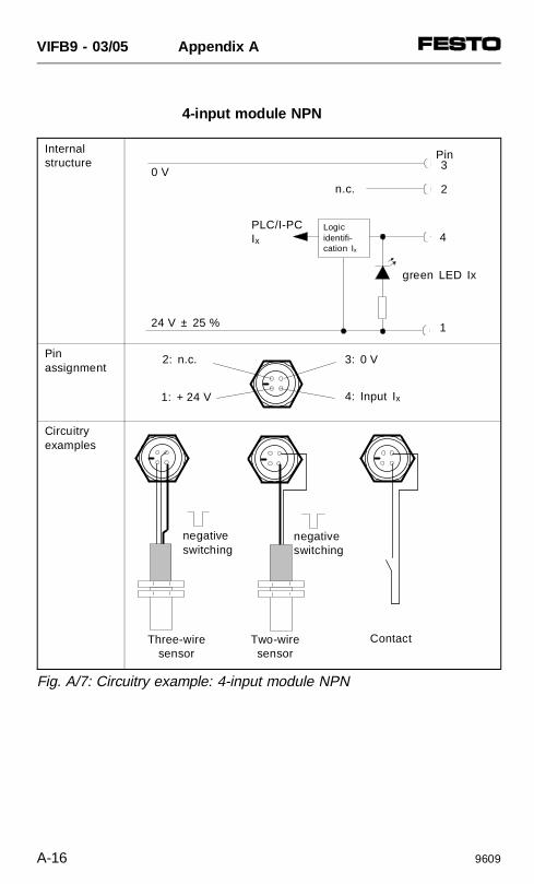
4-input module NPN
negativeswitching
negativeswitching
4
1
Logicidentifi-cation Ix
n.c.
PLC/I-PCIx
24 V ± 25 %
0 V
3: 0 V
4: Input Ix
2: n.c.
1: + 24 V
green LED Ix
ContactTwo-wiresensor
Three-wiresensor
2
3PinInternal
structure
Pinassignment
Circuitryexamples
Fig. A/7: Circuitry example: 4-input module NPN
VIFB9 - 03/05 Appendix A
A-16 9609
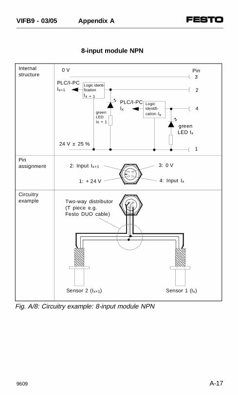
8-input module NPN
AAAAAAAAAAAAAAAAAAAAAAAAAAAAAAAAAAAA
AAAAAAAAA
AAAAAAAAAAAAAAAAAAAAAAAAAAAAAAAAAAAA
Sensor 2 (Ix+1) Sensor 1 (Ix)
Pin3
4
1
Logicidentifi-cation Ix
PLC/I-PCIx+1
24 V ± 25 %
0 V
3: 0 V
4: Input Ix
2: Input Ix+1
1: + 24 V
Two-way distributor(T piece e.g. Festo DUO cable)
Logic identi-ficationIx + 1
PLC/I-PCIx
greenLED Ix
green LEDIx + 1
2
Internal structure
Pinassignment
Circuitry example
Fig. A/8: Circuitry example: 8-input module NPN
VIFB9 - 03/05 Appendix A
9609 A-17
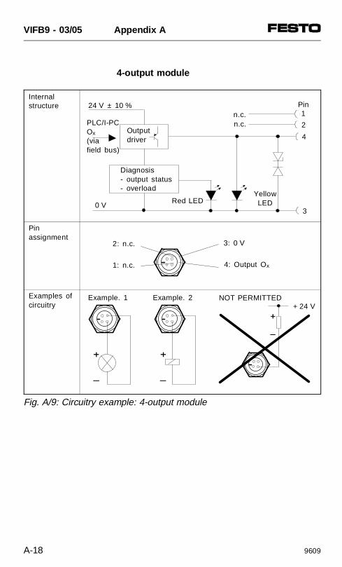
4-output module
Internal structure
Pinassignment
Examples of circuitry
Fig. A/9: Circuitry example: 4-output module
NOT PERMITTEDExample. 2
Pin1
4
3
PLC/I-PCOx
(via field bus)
24 V ± 10 %
0 V
3: 0 V
4: Output Ox
2: n.c.
1: n.c.
Example. 1
Outputdriver
YellowLED
+ 24 V
Red LED
Diagnosis- output status- overload
n.c. 2n.c.
VIFB9 - 03/05 Appendix A
A-18 9609

INDEX
VIFB9 - 03/05 Index
9707 B-1

VIFB9 - 03/05 Index
B-2 9707
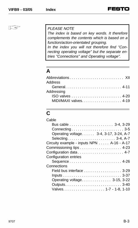
AAbbreviations . . . . . . . . . . . . . . . . . . . . . . . . . . XIIAddress
General. . . . . . . . . . . . . . . . . . . . . . . . . . . 4-11Addressing
ISO valves . . . . . . . . . . . . . . . . . . . . . . . . 4-20MIDI/MAXI valves. . . . . . . . . . . . . . . . . . . 4-19
CCable
Bus cable . . . . . . . . . . . . . . . . . . . . . 3-4, 3-29Connecting . . . . . . . . . . . . . . . . . . . . . . . . . 3-5Operating voltage. . . . . . 3-4, 3-17, 3-24, A-7Selecting. . . . . . . . . . . . . . . . . . . . . . . 3-4, A-7
Circuity example - inputs NPN . . . . . A-16 - A-17Commissioning tips . . . . . . . . . . . . . . . . . . . . 4-23Configuration data . . . . . . . . . . . . . . . . . . . . . . 4-7Configuration entries
Sequence . . . . . . . . . . . . . . . . . . . . . . . . . 4-26Connections
Field bus interface . . . . . . . . . . . . . . . . . . 3-29Inputs . . . . . . . . . . . . . . . . . . . . . . . . . . . . 3-37Operating voltage. . . . . . . . . . . . . . 3-15, 3-22Outputs. . . . . . . . . . . . . . . . . . . . . . . . . . . 3-40Valves. . . . . . . . . . . . . . . . . . . . 1-7 - 1-8, 1-10
PLEASE NOTEThe index is based on key words. It thereforecomplements the contents which is based on afunction/action-orientated grouping.In the index you will not therefore find "Con-necting operating voltage" but the separate en-tries "Connections" and Operating voltage".
VIFB9 - 03/05 Index
9707 B-3
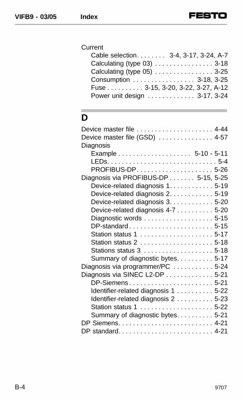
CurrentCable selection. . . . . . . . 3-4, 3-17, 3-24, A-7Calculating (type 03) . . . . . . . . . . . . . . . . 3-18Calculating (type 05) . . . . . . . . . . . . . . . . 3-25Consumption . . . . . . . . . . . . . . . . . 3-18, 3-25Fuse . . . . . . . . . . 3-15, 3-20, 3-22, 3-27, A-12Power unit design . . . . . . . . . . . . . 3-17, 3-24
DDevice master file . . . . . . . . . . . . . . . . . . . . . 4-44Device master file (GSD) . . . . . . . . . . . . . . . 4-57Diagnosis
Example . . . . . . . . . . . . . . . . . . . . 5-10 - 5-11LEDs. . . . . . . . . . . . . . . . . . . . . . . . . . . . . . 5-4PROFIBUS-DP. . . . . . . . . . . . . . . . . . . . . 5-26
Diagnosis via PROFIBUS-DP . . . . . . . 5-15, 5-25Device-related diagnosis 1. . . . . . . . . . . . 5-19Device-related diagnosis 2. . . . . . . . . . . . 5-19Device-related diagnosis 3. . . . . . . . . . . . 5-20Device-related diagnosis 4-7 . . . . . . . . . . 5-20Diagnostic words . . . . . . . . . . . . . . . . . . . 5-15DP-standard . . . . . . . . . . . . . . . . . . . . . . . 5-15Station status 1 . . . . . . . . . . . . . . . . . . . . 5-17Station status 2 . . . . . . . . . . . . . . . . . . . . 5-18Stations status 3 . . . . . . . . . . . . . . . . . . . 5-18Summary of diagnostic bytes. . . . . . . . . . 5-17
Diagnosis via programmer/PC . . . . . . . . . . . 5-24Diagnosis via SINEC L2-DP . . . . . . . . . . . . . 5-21
DP-Siemens . . . . . . . . . . . . . . . . . . . . . . . 5-21Identifier-related diagnosis 1 . . . . . . . . . . 5-22Identifier-related diagnosis 2 . . . . . . . . . . 5-23Station status 1 . . . . . . . . . . . . . . . . . . . . 5-22Summary of diagnostic bytes. . . . . . . . . . 5-21
DP Siemens. . . . . . . . . . . . . . . . . . . . . . . . . . 4-21DP standard. . . . . . . . . . . . . . . . . . . . . . . . . . 4-21
VIFB9 - 03/05 Index
B-4 9707
DP-master (standard) . . . . . . . . . . . . . . . . . . 4-49Bus parameter/reaction times . . . . . . . . . 4-56Cyclic exchange of data. . . . . . . . . . . . . . 4-54Fetch diagnostic information . . . . . . . . . . 4-53General. . . . . . . . . . . . . . . . . . . . . . . . . . . 4-47Implemented functions . . . . . . . . . . . . . . . 4-56Send parametrizing data . . . . . . . . . . . . . 4-50Service access points (SAP) . . . . . . . . . . 4-56
EEarthing
Components . . . . . . . . . . . . . . . . . . . . . . . . 2-6Valve terminal . . . . . . . . . . . . . . . . 3-19, 3-26
EMERGENCY STOP. . . . 3-16, 3-21, 3-23, A-10,. . . . . . . . . . . . . . . . . . . . . . . . . . . A-12 - A-13
ErrorsLED display . . . . . . . . . . . . . . . . . . . . . . . . 5-5Status bits . . . . . . . . . . . . . . . . . . . . . . . . 5-11Treatment . . . . . . . . . . . . . . . . . . . . . 5-3, 5-30
FField bus interface . . . . . . . . . . . . . . . . . . . . . 3-29Fitting
Hat rail clamping unit . . . . . . . . . . . . . . . . . 2-8Hat rail fitting type 03. . . . . . . . . . . . . . . . 2-10Wall fitting type 03 . . . . . . . . . . . . . . . . . . . 2-9Wall fitting type 05 . . . . . . . . . . . . . . . . . . 2-12
FREEZE. . . . . . . . . . . . . . . . . . . . . . . . 4-25, 4-48Function
Node. . . . . . . . . . . . . . . . . . . . . . . . . 1-11, 3-7Valve terminal . . . . . . . . . . . . . . . . . . . . . . 1-3
FuseExternal . . . . . 3-15 - 3-16, 3-20, 3-22 - 3-23,. . . . . . . . . . . . . . . . . . . . . . . . . . . . 3-27, A-12Internal . . . . . . . . . . . . . . . . . 3-8, A-12 - A-13
VIFB9 - 03/05 Index
9707 B-5
GGeneral DP-master
Send parametrizing data . . . . . . . . . . . . . 4-50
IIcons . . . . . . . . . . . . . . . . . . . . . . . . . . . . . . . 4-32
LLED display
Inputs . . . . . . . . . . . . . . . . . . . . . . . . 5-8, 3-36Node. . . . . . . . . . . . . . . . . . . . . . . . . . . . . . 5-5Outputs. . . . . . . . . . . . . . . . . . . . . . . . . . . 3-39Valves. . . . . . . . . . . . . . . . . . . . . . . . 5-6 - 5-8
MModule consistency . . . . . . . . . . . . . . . 4-25, 4-48
NNetwork
Interface . . . . . . . . . . . . . . . . . . . . . . . . . . 3-29Node . . . . . . . . . . . . . . . . . . . . . . . . . . . 1-11, 3-8NPN . . . . . . . . . . . . . . . . . . . . . . . . . . A-16 - A-17
VIFB9 - 03/05 Index
B-6 9707
PPin assignment
Field bus. . . . . . . . . . . . . . . . . . . . . . . . . . 3-31Inputs . . . . . . . . . . . . . . . . . . . . . . . . . . . . 3-37Operating voltage. . . . . . . . . . . . . . 3-19, 3-26Outputs. . . . . . . . . . . . . . . . . . . . . . . . . . . 3-40
PNP . . . . . . . . . . . . . . . . . . . . . . . . . . A-14 - A-15PROFIBUS-DP . . . . . . . . . . . . . . . . . . . . . . . 4-24
Diagnostic information . . . . . . . . . . . . . . . 5-26Profile selection
Siemens . . . . . . . . . . . . . . . . . . . . . . . . . . 4-24
SSend parametrizing data
General DP-master . . . . . . . . . . . . . . . . . 4-50Short circuit
Fusing. . . . . . . . . 3-15, 3-20, 3-22, 3-27, A-12Siemens
Addressing example. . . . . . . . . . . 4-45 - 4-46Configuration COM ET200 V4.x . . . . . . . 4-28Configuration COM ET200 Windows V2.x . . . . . . . . . . . 4-33Configuration NCM S7-L2 V1.1 . . . . . . . . 4-44Configuration NCM S7-PROFIBUS V2.x . 4-39Configuration programs . . . . . . . . . . . . . . 4-22Configuration STEP 7 V2.x . . . . . . . . . . . 4-39Error diagnosis . . . . . . . . . . . . . . . . . . . . . 5-25Error location . . . . . . . . . . . . . . . . . . 5-3, 5-11Profile selection . . . . . . . . . . . . . . . . . . . . 4-24Settings . . . . . . . . . . . . . . . . . . . . . . . . . . 3-10Station no. . . . . . . . . . . . . . . . . . . . . . . . . 3-13Station selection COM ET200 V4.x . . . . . 4-27Station selection COM ET200 Windows . 4-31Station selection NCM S7-PROFIBUS V2.x . . . . . . . . . . . . 4-37Station selection STEP 7 V2.x. . . . . . . . . 4-37Status bits . . . . . . . . . . . . . . . . . . . . . . . . 4-25Sum identifier . . . . . . . . . . . . . . . . . . . . . . 4-35
VIFB9 - 03/05 Index
9707 B-7
Station selection . . . . . . . . . . . . . . . . . . . . . . 4-26Status bits
Siemens . . . . . . . . . . . . . . . . . . . . . . . . . . 4-25Sum identifier. . . . . . . . . . . . . . . . . . . . . . . . . 4-30Switching status
Inputs . . . . . . . . . . . . . . . . . . . . . . . . . . . . . 5-8Outputs. . . . . . . . . . . . . . . . . . . . . . . . . . . . 5-8
SYNC. . . . . . . . . . . . . . . . . . . . . . . . . . 4-25, 4-48System structure . . . . . . . . . . . . . . . . . . . . . . . 1-3
TTechnical specifications. . . . . . . . . . . . . . . . . A-3Test routine for valves. . . . . . . . . . . . . . . . . . . 5-9Type 03
Calculating inputs/outputs . . . . . . . . . . . . . 4-8Connecting the operating voltages . . . . . 3-15Connection example . . . . . . . . . . . . . . . . 3-20Description of components . . . . . . . . . . . . 1-5
Type 05Calculating inputs/outputs . . . . . . . . . . . . . 4-9Connecting the operating voltages . . . . . 3-22Connection example . . . . . . . . . . . . . . . . 3-27Description of components . . . . . . . . . . . . 1-9
VValves . . . . . . . . . . . . . . . . . . . . . . . . . . . . . . . 1-5Voltage
Cable selection. . . . . . . . . . . . 3-4, 3-17, 3-24Connecting . . . . . 3-15, 3-19, 3-22, 3-26, 3-29Switching on. . . . . . . . . . . . . . . . . . . . . . . . 4-6
WWeight
Calculation . . . . . . . . . . . . . . . . . . . . . . . . 2-10
VIFB9 - 03/05 Index
B-8 9707


![Valve terminal VTSA/VTSA-F VTSA… - Festo USA · Description Pneumatics 538923 1312h [8025774] Valve terminal VTSA/VTSA-F VTSA…](https://img.pdfslide.us/doc/110x75/5c273ee709d3f2246b8b5f4b/valve-terminal-vtsavtsa-f-vtsa-festo-usa-description-pneumatics-538923-1312h.jpg)
![MPA valve terminal - Festo...MPA pneumatics manual Valve terminal with MPA pneumatics Type VT32−.. Manual 534 241 en 0302NH [665 561] MPA valve terminal Contents and general instructions](https://img.pdfslide.us/doc/110x75/5ea5fab1dace5b6e75520cde/mpa-valve-terminal-festo-mpa-pneumatics-manual-valve-terminal-with-mpa-pneumatics.jpg)