Embed Size (px)
DESCRIPTION
Â
Citation preview

ARCHITECTURE STUDIO AIR STUDENT DESIGN JOURNAL ANDREA VALENZUELA 590512
STUDIO AIR APBL30048

2
INTRODUCTION
My name is Andrea Valenzuela. I am a third year architecture major at the University of Melbourne. I have chosen to pursue a career in the Architecture, Building and Planning discipline as it involves the use of both artistic skills and problem solving abilities, with a focus on the pursuit of sustainability in our natural and built environments. The most important thing that I have gained from the architecture major is the ability to the consider and appreciate world around us, built and natural, from anthropological, historical, technological and design perspectives. I have developed proficiency in design softwares such as AutoCAD, Google Sketchup and the Adobe creative suite through work experi-ence with T&Z architects and undertaking design based subjects throughout school and university. Above, the evocative model images submitted towards my second year Architecture Design Studio: Earth are shown. Architecture Design Studio: Air has been my first experi-ence working with the proscribed Rhinoceros and Grasshopper. From this subject, I hope to gain literacy and understanding of algorithmic softwares and the process of parametric design. The main objective is learning: to concieve a design which demonstrates ability surpassing that which I currently hold.

CONTENTS
INTRODUCTION 2 A.1 DESIGN FUTURING 4 A.2 DESIGN COMPUTATION 6 A.3 COMPOSITION/GENERATION 8 A.4 CONCLUSION 11 A.5 LEARNING OUTCOMES 11 B.1 RESEARCH FIELD 12 B.2 CASE STUDY 1.0 18 B.3 CASE STUDY 2.0 22 B.4 TECHNIQUE: DEVELOPMENT 26 B.5 TECHNIQUE: PROTOTYPES 28 B.6 TECHNIQUE: PROPOSAL 32 B.7 OBJECTIVES AND LEARNING OUTCOMES 42

4
A.1 DESIGN FUTURING Fresh Hills Artist Team: Matthew Rosenberg Artist Location: Los Angeles, USA2nd Place, 2012
Technology: Wind turbinesWind turbines installed in the artificial landscape, the form of which places the turbines in optimal position as it reaches up-wards towards levels of increased energy potential1.
Expanding Future Possibilities Employment of wind power technologies, which is not commonly used beyond simple wind turbines, ‘leads by example’.
Contribution to site and inhabitants: The bamboo forest in the centre offers an on site maintenance solution for the ‘skin’ and also functions as a community garden. Native vegetation is housed here, promoting engagement with the local environment. The central hub draws visitors as a place to gather and reflect; as opposed to turbine farms that isolate landscapes and prevent visitors.
This facilitates discourse and education about sustainable energy generation and inspires future possibility. Likeminded individuals with an interest in sustainable infrastructure are likely to be drawn to Fresh hills, facilitating positive community interaction and exchange of ideas between those who share common interests.
Contribution to ideas, ways of thinking: “The apparatus is generated from the grafting of fresh kills wind rose data onto the site”2. This design demonstrates connection between site-specific data and the designed structure. The symbi-otic relationship between site and design is as emphasized by the concept of organic architecture3. Critique: The scheme outlines plan for bamboo forest, but does not con-sider lifespan of bamboo cladding vs. growing time.No solution is offered to the noise generated by wind turbines; required in order to utilize the central hub as a community space. Should this be resolved, however, this design solution increases usability of the space even in times of low power generation potential.
1 “2012 Second Place Award Winner”, landartgenerator.org, Last Modified 2013, <http://landartgenerator.org/LAGI-2012/8Y8B8U8R/#>.2 Ibid. 3 William J.R. Curtis, “The architectural system of Frank Lloyd Wright”, in Modern Architecture Since 1900, (New York: Phaidon Press, 1996) pp 113-129.
Matthew Rosenberg, 2012, Electronic Image, landgenerator.org, <http://landartgenerator.org/LAGI-2012/8Y8B8U8R/#>, accessed 10 March 2014.
Ibid.

Technology: Solar panels due south. The slope of the running track is based on angles of optimum solar energy gain. South facing panels generate the most amount of electricity, on average, of all pos-sible orientations1. Pavegen kinetic energy converters are used in conjuction to harness kinetic energy of runners using the track, increasing energy output of the coaster2. Expanding future possibilities: This scheme introduces the concept of attracting users and generating energy as part of one unified strategy. The idea is transportable, applicable to any site. Contribution to site and inhabitants:Creation of usable space, which promotes exercise and healthy living, community, and the harmonious relationship with wildlife and landscape. The raised track leaves animals undisturbed and minimizes need for clearance of natural vegetation. Contribution to ideas, ways of thinking:The combination of kinetic and solar energy iterates that a single design is not limited to a single form of energy generation.Humans are in many ways responsible for environmental dam-age, this initiative allows them to also be the solution. The ability to contribute fosters interest in environmental and sustainability issue. This opens up the question of how else we can help. Critique:The scheme assumes humans to be heavily environmentally and/or fitness motivated. While the gradients of the track optimize solar gain, the steep slopes create a strenuous circuit and are likely to deter potential users. The design is likely to produce seasonal benefit. Lack of sunlight is often accompanied by cold weather in autumn and winter. It is likely that less people will run in this weather. The coaster will experience simultaneous reduc-tions in energy output through both the solar and kinetic generator systems during the colder months.
1 “Your Solar Panels Aren’t Facing the Wrong Way”, Forbes, last modified 11 November 2013, <http://www.forbes.com/sites/tomkonrad/2013/11/22/your-solar-panels-arent-facing-the-wrong-way/>. 2 “FRESH KILLS COASTER”, landartgenerator.org, Last Modified 2013, <http://landartgenera-tor.org/LAGI-2012/XWWXWW11/#>.
A.1 DESIGN FUTURING Fresh Kills Coaster Artist Team: Jason Shannon, Paola Yanez Artist Location: Jersey City, USA
Jason Shannon, Paola Yanez, 2012, Electronic Image, landgenerator.org, <http://landartgenerator.org/LAGI-2012/XW-WXWW11/#>, accessed 10 March 2014.
Ibid.

6
A.2 DESIGN COMPUTATION Case studies: Computing self organisation: Environmentally sensitive growth modelling. Material behaviour embedding physical properties in computational design processes.
Computational design has affected the design process by enabling a dynamic, visualized design process, rather than fabricating a preconceived idea, as in computerisation. The result is an increase in creativity of design solutions, both visually and structurally. It may be argued that a visually experimental design process encourages prioritization of form over materiality, “in the virtual space of digital design, form and force are usually treated as separate entities – divided into processes of geometric form generation and subsequent engineering simulation”1
This method of design development resembles that employed by Frank Gehry and Antonio Gaudi: conception of form before func-tion, and post-justification of aesthetic agenda.
What are the ongoing and incoming changes within the design and construction industries? The introduction of 3D modelling software and parametric/algo-rithmic design strategies, as discussed above, have shifted the paradigm of design conception techniques. The capacity for gen-erative design is expanding with such advancements as can be seen in these case studies: consideration of natural behaviours. Computational design can no longer be seen to seperate desing-ers from their physical context. Technological innovations have been made possible by the employment of ‘modern’ materials such as plate glass, steel, iron, reinforced concrete e.g. curtain walls. An understanding of the influence of materiality on form fosters generation of holistic designs that are well integrated with function2. Design strategies have encompassed the relationships between influences such as function and materiality in response to a change in societal values, where sustainability may conflict with long standing economic concerns.
1 Moritz Fleischmann et al., “material behaviour embedding physical properties in computa-tional design processes” Architecture Design 82, 2 (March 2008), http://onlinelibrary.wiley.com.ezp.lib.unimelb.edu.au/store/10.1002/ad.1378/asset/137_ftp.pdf?v=1&t=hsyhwhqk&s=9706b39ac5a73717e6ab68aa6d13623b784c0c50.2 Ibid. Quote Source: Ibid.
“Design computation provides the possibilities of integrating physical properties andmaterial behaviour as generative drivers in the architectural design process. Thus architectural form, material formation and structural performance can be considered synchronously”.
The form-found structural analysis model enables simula-tion of residual stress. Moritz Fleischmann et al., 2008, digital image, http://onlinelibrary.wiley.com.ezp.lib.unimelb.edu.au/store/10.1002/ad.1378/asset/137_ftp.pdf?v=1&t=hsyhwhqk&s=9706b39ac5a73717e6ab68aa6d13623b784c0c50.

A.2 DESIGN COMPUTATION
How does computation impact on the range of conceivable and achievable geometries?Algorithmic softwares enable designers to explore infinite math-ematical possibilities. This has exponentially increased explora-tion and possibility with regards to geometric form. Employment of complex geometric form and supporting systems is encouraged by computerized design as it increases speed and efficiency in design conception and development. The project of plant growth modeling, as undertaken by the University of Alberta, Canada, is based around the premise of computing self-organisation. Self organization is based on mathematical, spatial models which are dynamic and progres-sive1. Technology now exists which is capable of simulating the effects over time on such mathematical algorithms considering a given set of influences. This is demonstrative of the progression of computer technology enabling 3D modeling programs to process increasingly complex mathematical principles. What does computation contribute to evidence and performance-oriented designing?Computerized building performance rating schemes such as NA-BERS and Green Star have reformed standards of performance orientation. Computational design increases propensity for con-sideration of feedback. The ICD/ITKE Research Pavilion 20104 project, material behaviour embedding physical properties in computational design processes, is an example of computerised design technology employing mathematical principles to evalu-ate design possiblities. This project focuses on elastic bending of bitch plywood and has produced bending-active computational simulation systems; which are equipped to respond to theoretical linear forces on a given material2.
Architecture has always progressed through the development of standard processes and components attributed to the architec-tural style or movement in question. Examples of this include the classical orders and the rules of the gothic. Modern architecture is no different: we have developed standardized methods for the construction of modern technologies, made possible my compu-tational design, such as curtain walls, trombe walls and reinforced concrete flooring systems. Contrary to the view presented by the futurist manifesto, the success of modern architecture and technology is derived from, and inspired by, innovative develop-ment through history. The computational design movement may be seen as another brick that will pave the way towards future prosperity.
1 “Computing Self-Organisation: Environmentally Sensitive Growth Modelling”, Architecture De-sign 2 (April 2006), http://onlinelibrary.wiley.com.ezp.lib.unimelb.edu.au/store/10.1002/ad.235/asset/235_ftp.pdf?v=1&t=hsyeuc6w&s=04c4fdb73dc210e225af8a051d314049f8c49f63\2 Moritz Fleischmann et al., “material behaviour embedding physical properties in computa-tional design processes” .
Plant growth modeling: computerised model of self organisation Architecture Design, 2006, digital image, http://onlinelibrary.wiley.com.ezp.lib.unimelb.edu.au/store/10.1002/ad.235/asset/235_ftp.pdf?v=1&t=hsyeuc6w&s=04c4fdb73dc210e225af8a051d314049f8c49f63\

8
Photovoltaic cells work to convert the energy of light directly into electricity via the photovoltaic effect that is, the creating of electric current upon exposure to light.
Thin film solar cells reduce material requirement for the creation of the solar cell. However, the solar cell is sandwiched between two panes of glass, as opposed to the single pane on a normal photovoltaic cell. As a result, thin-film cells are approximately twice as heavy. Moreover, the conversion rate of thin film lags by two to three percentage points1.
The typical monocrystalline solar cell is a dark black colour, and the corners of cells are usually missing as a result of the produc-tion process and the physical nature of monocrystalline silicon. Polycrystalline, on the other hand, is light or dark blue in colour with a much less uniform finish2.
Advantages of monocrystalline Monocrystalline solar panels have the highest efficiency rates since they are made out of the highest-grade silicon. The effi-ciency rates of monocrystalline solar panels are typically 15-20%. Monocrystalline also has the largest efficiency in terms of space. Since these solar panels yield the highest power outputs, they also require the least amount of space compared to any other types. Monocrystalline solar panels produce up to four times the amount of electricity as thin-film solar panels.Monocrystalline solar panels live the longest. They suffer less ad-verse effects on performance under increased temperatures than polycrystalline, and tend to perform better than similarly rated polycrystalline solar panels at low-light conditions.
Advantages of polycrystalline The manufacturing process for polycrystalline cells is simpler and cheaper. Les of the original silicon ends up as waste than in the production of monocrystalline cells. If a monocrystalline solar panel is partially covered with shade, dirt or snow, the entire circuit can break down3.
1 “Which Solar Panel Type is Best? Mono- vs. Polycrystalline vs. Thin Film, Energy Informative: The Homeowner’s Guide to Solar Panels”, accessed 26 April 2014, http://energyinformative.org/best-solar-panel-monocrystalline-polycrystalline-thin-film/#monocrystalline-silicon.2 “E20/435 SOLAR PANEL, SUNPOWER”, accessed 26 April 2014, http://www.solarchoice.net.
au/blog/monocrystalline-vs-polycrystalline-solar-panels-busting-myths/.
3 Which Solar Panel Type is Best? Mono- vs. Polycrystalline vs. Thin Film, Energy Informative: The Homeowner’s Guide to Solar Panels, accessed 26 April 2014, http://energyinformative.org/best-solar-panel-monocrystalline-polycrystalline-thin-film/#monocrystalline-silicon.
A.3 COMPOSITION/GENERATION Energy Research Photovoltaics
BigSun Energy, Crystalline Modules, Digital Image, http://www.bigsunenergy.com/category/products/mono-crystalline/
Landlearn NSW, Polycrystalline Silicon Solar Cells, Photograph, https://www.flickr.com/photos/landlearnnsw/4602432021/

A.3 COMPOSITION/GENERATION Energy Research Piesoelectrics
Piezoelectric ceramics when mechanically activated with pressure or vibration, have the capacity to generate electric voltages suf-ficient to spark across an electrode gap. Piezoelectric generators can be single layered or multilayered.
In single layered generators, pressing a button causes a spring-loaded hammer to apply a mechanical force to a rod-shaped single-layer piezoelectric ceramic. As a result of the piezoelectric effect, the ceramic element produces a voltage that passes across a small spark gap causing the fuel source to ignite.
Multilayer piezo generators consist of a stack of very thin (sub-millimeter-thick) piezoelectric ceramics alternated with electrodes. The electrical energy produced by a multilayer piezo generator is of a much lower voltage than is generated by a single-layer piezo generator, although the current produced is much higher than that of a single-layer1.
Pavegen, a multilayered Piezoelectric generator tile, converts the kinetic energy of every footstep on the tile into electricity.The en-ergy harvested by the Pavegen tile can immediately power off-grid applications such as pedestrian lighting, way-finding solutions and advertising signage or be stored in a battery. The wifi technology allows monitoring of energy generation data from any location in-cluding the site of implementation. Thie result is a user-interactive method of energy generation.
The top surface of the flooring unit is made from 100% recycled rubber from car tires and the base of the slab is constructed from over 80% recycled aluminium compounds and alloys. This minimizes use of embodied energy of production.
It is waterproof and so can be placed indoors or outdoors. The system can be simply retrofitted in place of existing flooring sys-tems as well as specified for new developments2.
1 “Piezoelectric Generators: Applications”, APC International LTD, accessed 26 April 2014, https://www.americanpiezo.com/piezo-theory/generators.html
2 “Applications”. Pavegen systems, accessed 24 April 2014, http://pavegen.com/technology.
Pavegen Systems, Digital Image, http://pavegen.com/technology
Ecofriend, Piezoelectric systems for green environment, Photograph, http://www.ecofriend.com/12-piezoelectric-systems-for-green-environment.html

10
A.3 COMPOSITION/GENERATION Literature and Practice
Most architectural practices are still limiting themselves to the for-mer, although a few strategies have been identified for integrating computational design into architecture:
First, and most commonly, computational designers form groups that work separately to the design team. These exist in practices such as Foster + Partners and Grimshaw.
Second, Computational design consultants, such as SMART solu-tions and Gehry Technologies may be hired by architectural firms.
Third is full integration of computation into the design process i.e. lack of separation between concept development and compu-tational technique allows for an inherently generative design procedure. Such firms as MOS and Facit homes have employed this strategy.
Fourth, an emerging model of software engineer/architects1
1 Ibid.
The introduction of computer-aided design has provoked different response strategies. The degree to which designers embrace the freedom and autonomy associated with the use of algorithmic design softwares affects the capacity of the designer to embark on a generative design process.
Scripting cultures:Scripting is the capability offered by design softwares that allows the user to adapt, customise and reconfigure software around their own preferences and modes of working. ‘Scripting language’ is often synonymous with ‘programming language1. Software modified by the designer through scripting provides a range of possibilities for creative speculation that are not possible using the software only as the manufacturers intended2.
An algorithm is a set of rules that precisely define a set of opera-tions. In parametric design, algorithms are the data inputs that inform the parameters of the design, in turn dictating its form3
A parametric model is a model wherein the parts of a design relate and change in a coordinated way as defined by the param-eters and dependencies stated4.
Employment of algorithmic thinking and parametric modelling makes the difference between computerisation and computation. Computerisation refers to the use of computers as a ‘virtual draft-ing board’ for the purpose of simplifying the editing process and increasing precision of drawings5. Computation furthers this by allowing designers to employ complex mathematical algorithms in their designs by way of utilising computer technologies in genera-tional design strategies6.
1 ’Mark Burry, “Scripting Cultures,” Architectural Design, June, 2011, 8. 2 Ibid.3 Introduction to Grasshopper. Directed by Modelab. New York: Modelab, 2013), Online video.
4 Introduction to Grasshopper. Directed by Modelab. (New York: Modelab, 2013), Online video.5 Brady Peters, “The Building of Algorithmic Thought”, Architectural Design, 2013, 10.6 Ibid.

A.3 COMPOSITION/GENERATION Existing Examples
Grimshaw architects: Southern cross station. The roof’s form plays a crucial role as part of the environmental envelope. An efficient ventilation mechanism, the canopy satisfies internal needs for diesel extraction as well as cooling1. Function being the main design focus here, it becomes evident that the development of form was removed from the initial design process. The visible disconnect between form and function may result from separation between computational designers and the primary design team.
MOS ArchitectsThe portfolio of work displayed by MOS architects has been described as “experimental” and “wilfully strange”2. MOS designs communicate a creativity that comes from an integrated under-standing of design intent and computational design. Element House is an exploration into the integration of the seemingly competing design considerations: systems, and shapes3. This is representative of the cohesion between form and function that can be achieved to its greatest extent when the design team integrates computational design with the formal design process.
1 “Southern Cross Station,” Grimshaw Architects, http://grimshaw-architects.com/project/southern-cross-station/.2 “MOS Architects Take on Humanitarian Design in Nepal”, Aleksandr Bierig, ArchDaily, last modified Dec 8 2013, http://www.archdaily.com/tag/nepal/.3 “Index”, MOS Architects, last modified 2014, http://www.mos-office.net.
Source: Grimshaw, Southern Cross Station, Photograph, http://grimshaw-architects.com/project/southern-cross-station/
Ibid. Ibid.
Source: MOS, Element House, Photograph, http://www.mos-office.net

12
A.3 COMPOSITION/GENERATION CONCEPT DEVELOPMENT Generation, Growth, Bioinspiration
Exercise A.3 has explored the progression from compositional de-sign to generative design. Progression and generation are related closely, in my mind, to the idea of growth and self-organisation. This theme also ties in with energy production. With nature and the growth of plants and animals as inspiration, I have looked towards case studies which have employed bio-inspiration and operate symbiotically with their environment.
MOS Architects: PS1 Afterparty The fluid, organic form taken by the streetscape installation named ‘afterparty’ is characteristic of the experimental forms created by the MOS team and their full integration of computation into the design process.
Bioinspiration The interior canopy structures resemble bats wings and similarly operate under tensile strength. Moreover, the mounds of the shelters are said to represent a primitive vernacular hut, which “reconcile technological change with innate bio-cultural memory” 1.
Consideration of site and passive designThe exterior cladding is of dark and rough fibre thatch which provides increased radiant thermal absorption. Shade is abundant with more than 90% UV protection.The interaction between existing airflows with site geometry and orientation were considered in the design placement to increase the effect of evaporative cooling. Through employment of concrete thermal mass, low pressure differential generates airflow through space2. Passive design can greatly assist the function of an energy generator requested by our design brief. This is shown by the wind rose shape of the Fresh Hills design, second place in the 2012 LAGI competition3.
1 Escape (Correspondence), (New York: MOS Architects 2014), online video.
2 Ibid.3 “2012 Second Place Award Winner”, landartgenerator.org, Last Modified 2013, <http://landartgenerator.org/LAGI-2012/8Y8B8U8R/#>.
The project of plant growth modeling, undertaken by the University of Alberta, Canada, has addressed the role of bio-inspiration in computerized design by successfully modelling the process of self-organisation. As seen in nature, plant growth is inherently self-generative; computerization of a growth formula signifies a great capacity for computer modeling to employ generative design. This has prompted the question: in what capacity can we use computer modeling to influence and represent our own organically inspired design in Architecture Design Studio: Air?1
1 “Computing Self-Organisation: Environmentally Sensitive Growth Modelling”, Architecture Design 2 (April 2006), http://onlinelibrary.wiley.com.ezp.lib.unimelb.edu.au/store/10.1002/ad.235/asset/235_ftp.pdf?v=1&t=hsyeuc6w&s=04c4fdb73dc210e225af8a051d314049f8c49f63\
Source: MOS, Afterparty, Photograph, http://www.mos-office.net
Ibid. Ibid.
Ibid.

A.4 CONCLUSIONThe project of plant growth modeling, undertaken by the University of Alberta, Canada, has addressed the role of bio-inspiration in computerized design by successfully modelling the process of self-organisation. As seen in nature, plant growth is inherently self-generative; computerization of a growth formula signifies a great capacity for computer modeling to employ generative design. This has prompted the question: in what capacity can we use computer modeling to influence and represent our own organically inspired design in Architecture Design Studio: Air?1
1 “Computing Self-Organisation: Environmentally Sensitive Growth Modelling”, Architecture Design 2 (April 2006), http://onlinelibrary.wiley.com.ezp.lib.unimelb.edu.au/store/10.1002/ad.235/asset/235_ftp.pdf?v=1&t=hsyeuc6w&s=04c4fdb73dc210e225af8a051d314049f8c49f63\
Ibid.
A.5 LEARNING OUTCOMES
Research undertaken on generative design as prompted by the part A assignment have impacted on my interpretation of the con-cept of generation. Based on this, my design approach intends to incorperate bioinspiration in mimicking the natural process of photosynthesis by harnessing solar energy in conjunction with producing kinetic energy.
Awareness of the nature in design is an innovative strategy in itself, as emphasised by the philosophy of Organic Architecture. A design solution that displays a visibly symbiotic relationship with it’s surroundings inherently promotes a value of unity between anthropocentric and biocentric forces. Promotion of such values facilitates discourse and education about sustainable energy generation and harvesting. The use of multiple generator types iterates that a single design is not limited to a single form of en-ergy generation. Moreover, the design strategy intends to employ adaptable technologies where possible, which can keep up to date with new developments.
Community and environment are both to benefit from the design outcome. The concept aims to attract users and generate energy as part of one unified strategy. The design will create a usable space which promotes community interaction and a harmonious relationship between wildlife and landscape.
Architectural computation, as opposed to computerisation, provides opportunities for designers to explore solutions that would be impossible to generate with the human mind alone. Employing algorithmic strategies into parametric design, as we are beginning to in grasshopper, has prompted an understanding of data flows in design. Most importantly, I have learned the parameters of a particular design are specified, not the shape. Form is a response to the series of constraints placed by the designer.
This knowledge is useful, also, when applied to compositional design. This awareness of the effect that self-imposed constraints take on my design possibilities would have greatly improved my responses to past design briefs. This understanding prompts the questions:
How relevant is this constraint?
It is derived from the brief, or is it an autonomous measure?
Is the placement of this constraint going to limit my capacity for experimentation with form? Will it limit the design function?
Is there a more creative way to satisfy the criteria?

14
B.1 RESEARCH FIELD Biomimicry Emergent Urbanism
Everything in nature, everything around us, can be put down to a set of interactions between scientific and mathematic principles. This, too, is the basis of computational design. We are now able to use technology to recreate the generative processes seen in nature. Technology is our newest, most opportunistic source of creation.
Economist Jeffrey Goldstein defines emergence as the arising of novel and coherent structures, patterns and properties during the process of self-organization in complex systems1. The emergent is unlike its parent components and cannot be reduced to the sum of its parts.
1 Jeffrey Goldstein. “Emergence as a Construct: History and Issues”, Emergence: Complexity and Organization 1, 1 (1999): 49–72. Quote Source: “The Meaning of Emergent Urbanism, after A New Kind of Science”, Matheiu Helie, Emergen-tUrbanism, last modified 21 May 2012, http://emergenturbanism.com.
“One could search through the ”computational universe” for patterns found in the natural world, and know their rules immedi-ately without necessarily understanding their behavior, which for complex systems defies analysis”1 This validates the concept of emergence; associated with spontaneity and randomness. This draws a parallel with the process of computerised design in that the possibilities extend beyond what can be conceptualized by the rational mind.
Matheieu Helie defines successful design, albeit with reference to urban centers, as being simple in its definition but emergent and complex in behavior, adopting the complexity of nature and computation as a design model2
1 “The Meaning of Emergent Urbanism, after A New Kind of Science”, Matheiu Helie, Emer-gentUrbanism, last modified 21 May 2012, http://emergenturbanism.com.2 “Decoding paradise - the emergent form of Mediterranean towns”, Matheiu Helie, Emer-gentUrbanism, last modified 9 April 2012, http://emergenturbanism.com/2008/12/21/decoding-paradise-the-emergent-form-of-mediterranean-towns.
In looking at computation as a component, or version, of the de-sign process, I have chosen to ask the question of how manmade technologies fit into the generative process: a characteristically natural phenomenon.
“All of nature is a computation”

B1. RESEARCH FIELD Biomimicry A Greenfield and a Constellation LAGI 2012
The concept of emergence has been explored through the behav-iour of the dynamic land art entry to the 2012 LGI competition, A Greenfield and a Constellation.
The project consists of a large number of small outdoor radio-controlled flying devices. The installation is bio-inspired in that the devices are self-organised1.
Energy for flight generated by ‘tandem cells’ (solar energy, glows at night) making up an impact resistant skin on the attractors and replicants. The project employs the use of micro batteries, solar batteries, accumulators, LED lights and GPS navigators: all well known and easily accessible technologies2. While the project does not display any progressive or innovative technological solu-tions, this decision has expanded capacity for concentration on component interaction and dynamics.
A Greenfield and a Constellation employs two categories of flying devices: Attractors and Replicants. The attractors make up only 1% of all devices, and do not differ in appearance. The attractor organizes a large group of replicants, indicating how they should behave within their radius of action3. This system displays com-mon properties of emergent phenomena.The system correlates the separate lower-level components into a higher-level unity. The correlation spans across several components, therefore observation of emergence is of component behaviour on a macro level4The system evolves over time, in this case to generate different patterns such as a flag, a flock, a city skyline and a constellation5.
Both attractors and replicants keep safety distances among themselves and within the visitors. They automatically correct their flight patterns following these safety rules6. The behaviour of the flying devices is therefore based on algorithmic data input, drawing a parallel with the parametric design process.
1 “A Greenfield and a Constellation” landartgenerator.org, Last Modified 2013, http://landart-generator.org/LAGI-2012/eql7fj66/#.
2 Ibid.3 Ibid.4 Jeffrey Goldstein. “Emergence as a Construct: History and Issues”, Emergence: Complexity and Organization 1, 1 (1999): 49–72. 5 “A Greenfield and a Constellation” landartgenerator.org, Last Modified 2013, http://landart-generator.org/LAGI-2012/eql7fj66/#. 6 Ibid.
Carlos Campos and Yamila AIub, 2012, Electronic Image, landgenerator.org, <http://landartgenerator.org/LAGI-2012/XW-WXWW11/#>, accessed 5 April 2014.
Ibid.
Ibid.

16
B.1 RESEARCH FIELD Material Performance ICD/ITKE Research Pavilion 2010 Universitat Stuttgart
In looking at material performance, I chose to pursue the earlier mentioned 2010 research of the Institute of Computational Design at the Universitat Stuttgart.
The ICD/ITKE Research Pavilion project of 2010 employs material-oriented computational design. Material properties and responses to outside pressures can now be written as algorithms and therefore be considered in 3D modelling and simulation. The research pavilion project focuses on elastic bending behaviour of birch plywood strips, the main material employed in the construc-tion of the pavilion, and has produced results that lead to design possibilities of bending-active systems which are structurally equipped to respond to linear forces1. Stored energy from elastic bending in conjunction with the morphological differentiation of joint locations enables construction using only 6.5mm birch plywood sheets; despite a diameter of over twelve meters2. The process involves FEM simulation, that is, Finite Element Modelling. The modelling process begins with the planar distribu-tion of the 80 strips and proceeds to simulate the elastic bending process of the plywood in a mesh topology model3. The resulting model has been the basis of the form taken by the Pavilion itself, the finished structure visually communicating the internal stresses created by the visible bending of materials due to external forces.
1 “ICD/TKE Research Pavilion 2010” Prof. Achim Menges, Universitat Stuttgart Institute for Computational
design, accessed 2 April 2014, http://icd.uni-stuttgart.de/?p=4458.
2 Ibid.3 Ibid.
“Material computes. Any material construct can be considered as resulting from a system of internal and external pressures and constraints. Its physical form is determined by these pressures”.
“Whereas in the physical world material form is always inseparably connected to external forces, in the virtual processes of computational design form and force are usually treated as separate entities”.
Roland Halbe, ICD/ITKE Research Pavilion 2010, Photograph, http://icd.uni-stuttgart.de/?p=4458
Ibid.
Ibid.

B1. RESEARCH FIELD Material Performance Voussoir Cloud IwamotoScott Architects
Through performance analysis of the employed thin wood laminate material, and thorough engagement with mathematical principles, the Voussoir Cloud stands in pure compression1. The structure is made up of a system of vaults, forming a series of five columns, which rely on each other and three walls to maintain the pure compressive form. The material density increases towards the vault edges2.
Each vault is comprised of a Delaunay tessellation. Greater cell density of smaller more connective modules, or petals, gang together at the column bases and at the vault edges to form strengthened ribs, while the upper vault shell loosens and gains porosity3. The weight of the structure, as a result, is concentrated close to the ground. This reduces the effects of gravitational forces on the vaulting, while holding the lightweight structure to the ground by the denser columns.
In mathematics and computational geometry, a Delaunay trian-gulation for a set P of points in a plane is a triangulation DT(P) such that no point in P is inside the circumcircle of any triangle in DT(P). Delaunay triangulations maximize the minimum angle of all the angles of the triangles in the triangulation4. The triangular form is one of the strongest, hence employment of triangulation in the Voussoir Cloud.
Design development strategiesPhysical testing: The work of Antonio Gaudi is referenced in the project with the testing of physical models in assessing material performance. Material folding was tested in the voussoir cloud initially by using handmade models. This allowed examination of geometric relationships resulting from bending the proscribed material along a curved seam5.Computation: The curvature of each petal is dependant on its adjacent voids. Each petal has a unique geometry, calculated and calibrated to fit into the overall form. In turn, each cell behaves differently based on size, edge conditions and position within the structure. This was achieved through the development of a computational script for the rhino model which managed the petal edge plan curvature as a function of a tangent offset6. 1 “Voussoir Cloud”, Iwamotoscottarchitecture, Accessed April 2 2014, http://www.iwamotoscott.com/VOUSSOIR-CLOUD.2 Ibid.3 Ibid.
4 “Voronoi Diagrams and Delaunay Tesselation”, Kristof Van Laerhoven, accessed 2 April 2014, http://www.comp.lancs.ac.uk/~kristof/research/notes/voronoi/
5 “Voussoir Cloud”, Iwamotoscottarchitecture, Accessed April 2 2014, http://www.iwamotoscott.com/VOUSSOIR-CLOUD.6 Ibid.
IwamotoScottArchitecture, Voissoir Cloud, Photograph, http://www.archivenue.com/voussoir-cloud-by-iwamotoscott-with-buro-happold/
Kristof Van Laerhoven, Delaunay triangulation, on top of the Voronoi diagram (in dotted lines), Digital Image, http://www.comp.lancs.ac.uk/~kristof/research/notes/voronoi/
IwamotoScottArchitects, VOUSSOIR CLOUD

18
B.2 Case study 1.0 Iterations Matrix Voussoir Cloud


20
B.2 Case study 1.0 Iterations Matrix Voussoir Cloud Intent Illustrative Examples
Greater cell density of smaller more connective modules, or petals, gang together at the column bases and at the vault edges to form strengthened ribs, while the upper vault shell loosens and gains porosity. This results in increased gravitational force towards ground level where denser columns are formed.
2 The intention of this iteration is to accentuate the top to bottom vertical progression from loose vaults to dense ribs. This was achieved by increasing collecting the points surrounding centroids, at the bottom of the structure, into single vertices. In conjuction, an increase in scale of the voronoi tessellation, shown above, ac-centuates the ‘top-heavy’ look of the Voussoir Cloud. This iteration has an increased U count in the UV mesh component; a greater number of panels is more accommodating to shapes of increased geometric complexity.
1 Greater cell density of smaller more connective modules, or petals, gang together at the column bases and at the vault edges to form strengthened ribs, while the upper vault shell loosens and gains porosity. This results in increased gravitational force towards ground level where denser columns are formed.

The shape, size and curvature of each petal is dependant on its adjacent voids. Each petal has a unique geometry, calculated and calibrated to fit into the overall form.
3 The sharpness of this iteration was intended to convey the dynamic nature of the petal form. Each petal is unique, respond-ing to the input parameters of the grasshopper definition. This variation of the definition has accentuated this point by instruct-ing some petals to take a sharp and elongated form that differs greatly from their original form.
4 This iteration represents the calibration of petal forms to fit into, and to create, the overall form. The representative panels are visibly bulging and concaving to accommodate for the definition adjustments which have resulted in ‘folding’ of the vaulted forms. This iteration is of visual interest as it documents a movement towards creating an inverse of the original Voissour Cloud form.

22
B.3 CASE STUDY 2.0 EXOTIQUE PROJECTiONE architects
EXOtique installation was constructed as part of a design and fabrication workshop at Ball State’s college of architecture. The installation is a hexagonally based component system, which serves as a lit drop-ceiling. The design was generated entirely through grasshopper1. Being a student workshop project, there were considerable con-straints imposed. The time frame was a mere 5 days: one day for concept development, one day for modelling, and three combined days for fabrication, assembly and installation2. The budget, at $500, limited material and lighting possibilities. The structure was lit using upward facing globes connected to a collection of the panels by solid acrylic connectors. The styrene panels are also held together by solid acrylic connectors, bending within the component as opposed to at the edges3.
“Imagination can act as renderer”
The intent of the project was to express computation as a means of reducing the tedium of the fabrication process, as opposed to a tool for graphic representation4. This is effective as a mode of education as the students carried out the process, from com-puterised design generation through to construction. The role of computation is clear from the finished product. The project has set out to experiment with non-planar geometry. This was success-fully achieved through bending and folding of the styrene; each panel has its own curvature. The intent of the project was well expressed through its execution. The project inherently considers the fabrication process, being a design and fabrication workshop installation.
1 “EXOtique” Projectione, accessed 11 April 2014, http://www.projectione.com/exotique/2 Ibid.3 Ibid.4 Ibid.
PROJECTiONE, EXOtique, Photograph, http://www.projectione.com/exotique/
Ibid.

PROJECTiONE, EXOtique, Photograph, http://www.projectione.com/exotique/
Ibid.

24
Using the hexgrid function and offsetting the hexagonal shape, we have created a hexagonal pattern which mimics the panel tessellation of the EXOtique installation. The integers used for the grid were odd numbers in order to satisfy the tessellation requirements of the hexagonal shape. We have used an x integer of 3 and y integer of 5.
After establishing the hexagonal grid pat-tern, we established a panel space using this grid as a base. The box is created by the joining of points, whose locations are informed by the grid geometry through use of the subtract command. -The rectangular space serves as a panel, which allows the hexagonal pattern to be applied to our lofted surface.
Applying the loft command to a collection of curves creates a planar surface to which the hexagonal panel geometry can be applied. The lofted plane is representative of the lofted shape of the EXOtique instal-lation.
SimilaritiesThe organic curvature of the loft is held within a primarily rigid geometric frame. The hexagonal panels follow the curvature of the loft, rather than being two-dimensional pieces placed together to create a lofted shape.
DifferencesThe configuration of the circular cut-outs is dissimilar to that of our definition in that our circular pattern expressed itself in singular lines, rather than a concentric configuration. EXOtique is lit with LED bulbs attached to some panels, the circles are only present on the panels which are not lit. We could not replicate the inconsistency of the circular patterning, as we could not find a way to instruct point charges to only effect certain portions of the grid surface.The outside edges of EXOtique are limited to the borders of the hexagonal shapes, rather than adhering to the shape of the lofted surface. Where would we take this definition next? We aim to improve on the differences in order to recreate EXOtique with our definition as successfully as possible, before experimenting beyond the constraints of the original form. From here, we would increase dimensionality by splitting the lofted plane to fold it into different directions. Additionally, we would extrude some panels to create a more 3 dimensional effect.We would increase the ‘sharpness’ of the form by implementing panelised ribs which would protrude from the loft.
1 Hexagonal Grid 2 Box 3 Loft
B.3 CASE STUDY 2.0 EXOTIQUE Development Diagram
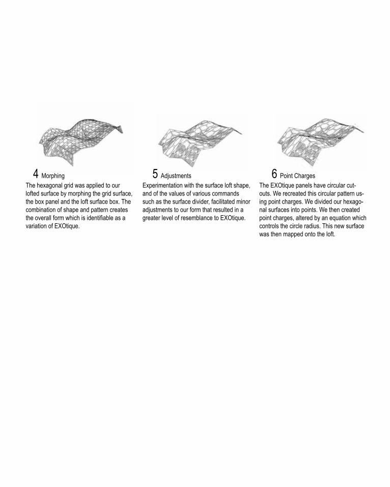
The hexagonal grid was applied to our lofted surface by morphing the grid surface, the box panel and the loft surface box. The combination of shape and pattern creates the overall form which is identifiable as a variation of EXOtique.
Experimentation with the surface loft shape, and of the values of various commands such as the surface divider, facilitated minor adjustments to our form that resulted in a greater level of resemblance to EXOtique.
The EXOtique panels have circular cut-outs. We recreated this circular pattern us-ing point charges. We divided our hexago-nal surfaces into points. We then created point charges, altered by an equation which controls the circle radius. This new surface was then mapped onto the loft.
4 Morphing 5 Adjustments 6 Point Charges

B.4 TECHNIQUE: DEVELOPMENT Geometric panelling iterations inspired by EXOTIQUE


28

B5. TECHNIQUE: PROTOTYPES
1. In this rendering we looked at removing the curve at one end of the structure and replacing it with a point, resulting in a pinched end. By removing the surface and considering piping in isolation, we can consider placement of piezoelectric ceramics within them that will react to external factors such as wind and human contact. To create maximum accessibility and efficiency, this structure would be placed with the pinched end facing south east to the site to maximize exposure to strong winds and direct the flow of people from the area adjoining to existing infrastructure to the waterfront.
2. In this prototype, the geometric piping was offset to create a double layered structure joined at it’s termination. The result is an arched structure which could be used as an underpass, or more sculpturally rotated on its side or cantilevered over the water. The piping could be fitted with piezoelectric ceramics to hardness en-ergy from passing wind, or clad in photovoltaic panels to harness solar energy.
Both prototypes 1 and 2 would be effectively prototyped via experimentation with bending of wire.
1
2
Experimentation with geometry: Panelling prototype

30
B5. TECHNIQUE: PROTOTYPES
3. Turning tower is a made up of stacked rectangular modules which move independently in response to wind movement. In it’s initial state, the modules take a full revolution, adopting a double helix type form. The movement of these modules will harness kinetic energy through piezoelectric generators. My observing the patterns of movement of the structure, users can engage with the site and be provided with a level of understanding of natural site conditions. The modules can also be cladded or constructed entirely of photo-voltaic cells. The nature of the form enables collection of sunlight from the full 360 degree spectrum on the site. In terms of site placement, to tower would be place on the north west corner. This position is waterfront, exacerbating the effects of windflow, and is removed from the shadows of surrounding infrastructure allowing maximum solar gain.

This prototype is an enlarged matrix of pipes which will fuction as tunnels adjoining to the central space. The large open-ings could create wind tunnels through the structure, affecting piezoelectric panel surfaces in order to generate kinetic energy. These panels will be used in the construction of doors between the piped tunnels and interior space. They will move on latches and close off different areas in response to changes in wind velocity, creating a dynamic user experience.
The doors closing further in response higher wind velocities optimizes energy gain from areas of high wind velocities by automatically placing the piezo panels perpendicular to the force. This also protects the interior space from strong wind tunnels, as doors will be further closed in those areas. We have considered using transparent, coloured peizo cells for these doorways which would use a small percentage of the energy generated to light up. The result would be a projection onto the floor of the interior space, which represents the wind-rose data on which the design in modeled, in a way that responds to the dynamic nature of wind patterns. Larger projections denote stronger winds.
The walls of the structure could be lined with photovoltaic cells that would be able to harness the energy from the sun in the day. These would also be working at an efficient level, as the triangulated panel surface accommodates for the angling of individual panels in order to optimize solar gain.
By using both photovoltaic cells and kinetic energy, year-round energy production can be ensured: reduction in solar gains in darker winter moths would be offset by increased kinetic energy output facilitated by an increase in average wind speeds.
B5. TECHNIQUE: PROTOTYPES

32
B6. PROPOSAL Energy Research Continued Piezo Actuators
A piezoelectric sensor converts a physical parameter, such as acceleration or pressure, into an electrical signal. In some sensors the physical parameter acts directly on the piezoelectric element; in other devices an acoustical signal establishes vibrations in the element and the vibrations are, in turn, converted into an electrical signal. Often, the system provides a visual, audible, or physical response to the input1.
A piezo actuator converts an electrical signal into a precisely controlled physical displacement2. We plan to employ actuators to control the movement of elements within our structures, enabling the structure to respond to site conditions.
A stack actuator is essentially a motor, or a generator of motion, usually linear and limited in range. The amount of force that can be applied depends on the cross sectional area of the actuator3. Stack actuators will the fitted to the doors on the Phat Pipes struc-ture which will then respond to changes in wind velocity by closing off higher velocity areas. This protects the central space from large wind tunnels as doors are automatically further closed in these ar-eas, Moreover, this maximizes kietic energy gain my automatically placing peizo panels perpendicular to the wind forces of highest energy gain potential.
The other type of piezo actuator is a stripe actuator or bending actuator, in which thin layers of piezoelectric ceramics are bonded together; the thin layers allow the actuator to bend with a greater deflection but a lower blocking force than a stack actuator4.
Stripe actuator panels will be fitted to the rectangular modules of tessellation tower. Increase in wind velocity, as well as physically displacing the panels, will trigger the actuator to further accentu-ate this movement. This movement will cause further increase in pressure on the actuators and the movement will self perpetuate. The kinetic energy from this movement will be harnessed and sent to the city grid.
1 “Piezo Stack Actuators”, APC International LTD, accessed 26 April 2014, https://www.ameri-canpiezo.com/knowledge-center/piezo-theory/applications.html2 Ibid.3 Ibid.4 Ibid.


STUDIO AIR
GROUP 8. DANIEL - ANDREA - EMILY
LAGI 2014 INTERIM PRESENTATION

PhotovoltaicPhotovoltaic cells convert the energy of light directly into electricity. Monocrystalline solar cells: the most efficient, durable and space efficient crystalline cells. These cells are generally used in the form of panels, and so are applicable to our strategy of geometric panelling.
RESEARCH AND PRECEDENTS
Voussoir Cloud Voussoir cloud considers functional capacities of materials.This inspired integration of energy generation with material selection.
EXOtique EXOtique emphasises simplicity of fabrication using panelling. With consideration of embodied energy, we chose to employ this strategy.
PRECEDENTS AND ALGORITHMIC DESIGN STRATEGY
Piezoelectrics Piezoelectric ceramics when mechanically activated with pressure or vibration, have the capacity to generate electric voltages.
Piezoelectric sensors, such as piezo actuators, convert physical parameters such as acceleration or pressure into electrical signals that may act directly on the piezoelectric element.
ENERGY RESEARCH

SITE CONTEXT
1
2
3
Detailed Site Plan
Wind Direction
Legend1. This area was previously a basin, over time it was filled with materials used form the other buildings that were torn down.2. Landfill3. In this particular area, buildings used to exist and the old foundations are still in the ground.
Circulation Plan
Sun Path Diagram
Site Plan 1:1000 - Proposed Position
High Movement Medium MovementLow MovementAlternate Walkways
Refshaleoen Holding, Copenhagen

TESSELLATION TOWER
Tessallation Tower is a rotating energy generating scuplture. Solar energy is generated through the monocrystalline photovoltaic cells that clad the skin of the structure. Further energy is harnessed from wind movement through placement of piezoelectric actuators.
1. Monocrystalline solar cells:2. Clear Film Piezoelectric cells3. Monocrystalline solar cells:
1
23

PROJECTION PIPES
Design 2 is an interactive constellation of piped walkways leading to a central space. It is cladded in monocrystalline photovoltaic panels.
The doorways to the centre space will be constructed of coloured transparent piezoelectirc panels and fitted with actuators. These panelled doors project a wind rose to the floor of the central hub. 1. Larger projections denote higher wind velocities. 2. Users are protected from large wind tunnels. 3. Strong wind forces automatically place panels perpendicular to force, extracting maximum kinetic energy.
wind magnitude/velocity openness of door

INTEGRATION AND DIRECTION
Our intent is to create something that responds to the dynamism of on-site environmental factors in a way that is interactive with users. The challenge is to incorperate geometric complexity and express the experimental nature of parametric design, whilst maintaining navigability in our structure.

40
B6. PROPOSAL Written Rationale
We have interpreted the brief as prompting a design which em-ploys natural site conditions as a means of energy generation.Our intent is to create something that responds to the dynamism of on-site environmental factors in a way that is interactive with users. The challenge is to incorperate geometric complexity and expression of parametric design, while maintaining navigability in our structure.
Energy research
We chose to employ both solar and kinetic energy to ensure year-round energy production. When there is less sun in winder months, there is greater wind flow which is harnessed as kinetic energy.
Photovoltaic cells convert the energy of light directly into electric-ity. We have chosen to use monocrystalline solar cells: the most efficient, durable and space efficient and crystalline cells, which also suffer less adverse effects from temperature increase than polycrystalline.These cells are generally used in the form of pan-els, and so are applicable to our strategy of geometric panelling.
Piezoelectric ceramics when affected by pressure or vibration have the capacity to generate electric voltages.
We will be employing the use of piezo actuators, which convert electrical signals into physical displacement, to control the move-ment of elements within our dynamic, responsive structures.
Precedents and algorithmic design strategy
Our algorithmic design strategy, geometric panelling, has been influenced by our explorations of precedents Voussoir Cloud and EXOtique.
Consideration of material function, as in Voussoir cloud, inspired integra-tion between our generators and our structure, in turn informing our deci-sion to employ photovoltaic and piezoelectric paneling. EXOtique emphasizes the relative simplicity of panel fabrication. As embodied energy is a concern for sustainable development, we chose to integrate paneling into our design. Moreover, we will employ recycled steel from the surrounding industrial area for the frame in order to minimize cost and energy of transport and production.
The Voussoir cloud cells are based on the Delaunay tessellation, and EXO-tique on an offset hexgrid. Having worked with these geometric grid forms and achieving interesting results, we chose to continue down this pathway.

Design 1: Tessellation Tower Tessellation tower is a rotating solar and wind energy harnessing sculpture. Steel offcuts will make up the frame of the structure, which will be clad in mono crystalline photovoltaic cells and piezo-actuators. The tower itself is divided up into rectanglular modules, which move independently as a result of wind velocities affecting the piezo actuators. Each module will be covered in mono crystal-line photovoltaic cells on the top and the sides of the rectangular structure to harness solar energy. The tower visually demon-strates changes in wind patterns but is limited in user interaction. Design 2: Projection Pipes Projection Pipes is an interactive constellation of piped walkways cladded with photovoltaic cells and piezoelectric fitted doors. The pipe directions are based on overlayed summer and winter wind rose data for the site, maximizing kinetic energy potential. The central area will be a meeting point of all the pipes with sitting area for users. The door from each pipe to the central space is constructed of translucent, coloured piezoelectric panels. The doors are fitted with piezoelectric actuators which will detect changes in wind velocity and open or close the door in response. The greater the wind speed, the further the door closes. This places panels more perpendicular to stronger winds to optimize energy intake. The door colouring will be projected into the floor of the space; the door will be lit with a small percentage of the energy generated to emphasise the projection. Wider projections denote higher wind velocities (refer to diagrams). The interior space is protected from large wind tunnels as door are automati-cally further closed in these areas. The exterior of the structure is cladded mono crystalline photovoltaic panels which are triangu-lated to allow for individual angling for optimal light capture. We have taken into consideration Tessellation Tower in terms of top-down design and algorithmic design methods. Projection pipes offers a higher level of engagement with users, and the strategies employed to achieve this will be considered as we continue to develop the peizoelectric rectangular panel idea.
Site Context
Our site is Refshaeleon in Copenhagen harbor, the site is situated in an industrial area but it is also adjacent to the water, which is situated to the west of the site. The site is primarily an open space as it was originally an island in its own right, but was annexed to the larger island of Amager.
Our observations found that the site is exposed to stronger and more frequent south-eastern winds during both summer and winter seasons. As the site is an open plane it is directly affected by wind, therefore positioning our proposed design to the west of the site along the waterfront, maximizes wind energy potential as well as displacement from existing building shadows to maximize solar efficiency.
The site can be accessed through the west side via an existing dock and ferry service, as well as the eastern side adjoining to the mainland Amager. Our structure is accessible from all four direc-tions ensuring accessibility and minimizing pedestrian traffic. The western region will be densely populated due to the proximity and flux generated by the position of our designs. The density will drop towards the east due to existing infrastructure, as people make their way away from the structure.

42
B7. LEARNING OBJECTIVES AND OUTCOMES
Our interim submission presented two very different design pro-posals, tessellation tower and projection pipes. This demonstrates engagement with objective 2: ability to develop a variety of design possibilities.
Our design responses were developed with careful consideration towards innovative energy generation strategies. The piezo actu-ated panel strategy as applied to Tesselation tower received posi-tive feedback, we intend to carry this through to the final design. This demonstrates our engagement with the brief, as outlined in objective 1.
Our case studies, being Voussoir Cloud and EXotique, informed our intentions for construction and fabrication of Photovoltaic and Piezoelectric panel cladded structures. This expresses engage-ment with objective 6, relating to design analyses.
The focus in the Projection Pipes design proposal is on user interaction. The complexity of the form of this design was com-promised as a result. We received critique on the simplicity of this form and lack of aesthetic development. This encourages devel-opment in the area of objective 3 to express the knowledge and skills we have gained in the area of 3D modeling and parametric design form the algorithmic sketchbook and case studies.
Negative feedback in the area of layout and visual content prompts consolidation of objective 5: constructing persuasive arguments in the context of design proposals.
From our current design developments, we intend to maintain the energy generation strategy of piezoelectric actuator panels acting upon independently rotating rectangular modules. We are likely to discontinue pursuit of solar energy production in favour of focus-ing on applying our generators to a form which expresses our parametric design skills in accordance with objective 3. Moreover, our resulting design must engage with its users as well as its site, and facilitate engagement between the users and the surrounding landscape. Considering objective 5, greater care must be taken in the final presentation to assess effectiveness of our visual design representations.