Embed Size (px)
Citation preview
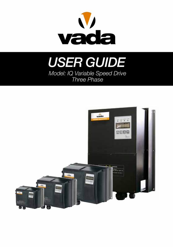
User GUideModel: IQ Variable Speed Drive
Three Phase

BLANK PAGE
│ 3
SAFETY PRECAUTIONS
PrefaceThank you for choosing Vada high performance IQ Drive series.
The IQ Drive is a dedicated pump drive designed for variable speed pumping systems.
The IQ Drive is manufactured with high quality components and materials and incorporates the
latest microprocessor technology.
Before installation and operation please read the instruction manual thoroughly.
Note: The information contained in this manual is subject to change without prior notice.
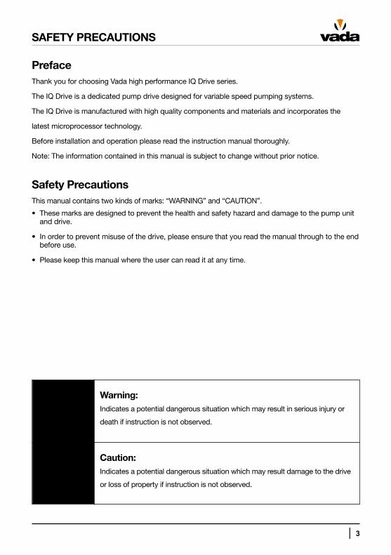
Safety PrecautionsThis manual contains two kinds of marks: “WARNING” and “CAUTION”.
• These marks are designed to prevent the health and safety hazard and damage to the pump unit and drive.
• In order to prevent misuse of the drive, please ensure that you read the manual through to the end before use.
• Please keep this manual where the user can read it at any time.
Warning:Indicates a potential dangerous situation which may result in serious injury or
death if instruction is not observed.
Caution:Indicates a potential dangerous situation which may result damage to the drive
or loss of property if instruction is not observed.
4 │
SAFETY PRECAUTIONS
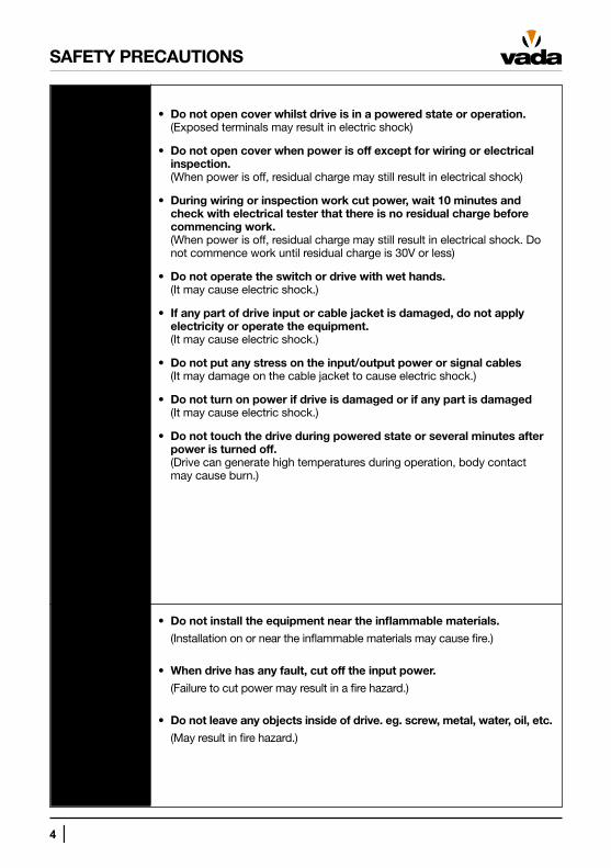
• Do not open cover whilst drive is in a powered state or operation.(Exposed terminals may result in electric shock)
• Do not open cover when power is off except for wiring or electrical inspection. (When power is off, residual charge may still result in electrical shock)
• During wiring or inspection work cut power, wait 10 minutes and check with electrical tester that there is no residual charge before commencing work. (When power is off, residual charge may still result in electrical shock. Do not commence work until residual charge is 30V or less)
• Do not operate the switch or drive with wet hands. (It may cause electric shock.)
• If any part of drive input or cable jacket is damaged, do not apply electricity or operate the equipment. (It may cause electric shock.)
• Do not put any stress on the input/output power or signal cables (It may damage on the cable jacket to cause electric shock.)
• Do not turn on power if drive is damaged or if any part is damaged (It may cause electric shock.)
• Do not touch the drive during powered state or several minutes after power is turned off. (Drive can generate high temperatures during operation, body contact may cause burn.)
• Do not install the equipment near the inflammable materials.
(Installation on or near the inflammable materials may cause fire.)
• When drive has any fault, cut off the input power.
(Failure to cut power may result in a fire hazard.)
• Do not leave any objects inside of drive. eg. screw, metal, water, oil, etc.
(May result in fire hazard.)
│ 5
SAFETY PRECAUTIONS
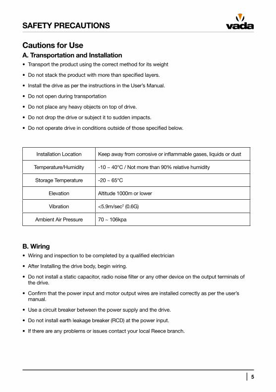
Cautions for UseA. Transportation and Installation• Transport the product using the correct method for its weight
• Do not stack the product with more than specified layers.
• Install the drive as per the instructions in the User’s Manual.
• Do not open during transportation
• Do not place any heavy objects on top of drive.
• Do not drop the drive or subject it to sudden impacts.
• Do not operate drive in conditions outside of those specified below.
Installation Location Keep away from corrosive or inflammable gases, liquids or dust
Temperature/Humidity -10 ~ 40°C / Not more than 90% relative humidity
Storage Temperature -20 ~ 65°C
Elevation Altitude 1000m or lower
Vibration <5.9m/sec2 (0.6G)
Ambient Air Pressure 70 ~ 106kpa
B. Wiring• Wiring and inspection to be completed by a qualified electrician
• After Installing the drive body, begin wiring.
• Do not install a static capacitor, radio noise filter or any other device on the output terminals of the drive.
• Confirm that the power input and motor output wires are installed correctly as per the user’s manual.
• Use a circuit breaker between the power supply and the drive.
• Do not install earth leakage breaker (RCD) at the power input.
• If there are any problems or issues contact your local Reece branch.
6 │
SAFETY PRECAUTIONS
C. Startup Checks• Check setup parameters before operating.
• Check to ensure that terminal block main power and control circuits are wired correctly as per the user manual.
• Use pressure sensors and low water level sensors specified by Vada.
D. Operation• Take care when turning on power as drive has automatic restart and recovery function and may
start immediately when power is applied.
• Do not modify or make changes to drive.
• Do not start or stop drive with electrical contactor installed at the power input.
• Install EMC filters when required to reduce impact from electromagnetic interference and protect nearby electrical equipment.
• Install input reactor when input voltage is unbalanced.
• Only use the drive on electric motors designed for use with variable frequency drives (motors of this type are protected against voltage spikes from the output of the drive.)
• If initialising parameters, setup is required as values will be reset to factory settings
E. Drive Failure or Malfunction• In order to prevent downtime of pump units, it is recommended that an auxiliary unit is installed.
• If drive fails or malfunctions, refer to Chapter 7.
│ 7
CONTENTS
Chapter 1. Basic Information 9
1.1 Nameplate Information 9
1.2 Drive Identification 9
Chapter 2. Specifications 10
2.1 Drive Specifications 10
Chapter 3. Dimensions 12
3.1 IQ-0075T ~ IQ-0220T 12
3.2 IQ-0400T 13
3.3 IQ-0550T ~ IQ-0750T 14
3.4 IQ-1100T ~ IQ-1500T 15
3.5 IQ-1850T ~ IQ-2200T 16
Chapter 4. Installation 17
4.1 Installation Precautions 17
4.2 Terminal Wiring Diagram 18
4.3 Main Power Supply Circuit Wiring 19
4.4 Control Circuit Wiring 21
Chapter 5. Operation 26
5.1 FND 26
5.2 Function Setup 29
5.3 Basic Operation 32
8 │
CONTENTS
Chapter 6. Function Table & Description 39
6.1 Present Status Display 39
6.2 Pump Control Group 40
6.3 Drive Control Group 42
6.4 Pump Control Group Parameter Functions 44
6.5 Drive Control Group Parameter Functions 52
Chapter 7. Troubleshooting 60
7.1 Fault History Table 60
7.2 Reset of Fault and Alarm 60
7.3 Troubleshooting Guide 61
│ 9
CHAPTER 1. BASIC INFORMATION
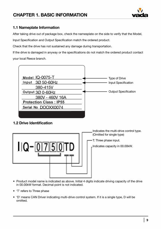
1.1 Nameplate Information
After taking drive out of package box, check the namesplate on the side to verify that the Model,
Input Specification and Output Specification match the ordered product.
Check that the drive has not sustained any damage during transportation.
If the drive is damaged in anyway or the specifications do not match the ordered product contact
your local Reece branch.
Type of DriveInput Specification
Output Specification
1.2 Drive Identification
Indicates the multi-drive control type. (Omitted for single type)
T: Three phase input.
Indicates capacity in 00.00kW.
• Product model name is indicated as above. Initial 4 digits indicate driving capacity of the drive in 00.00kW format. Decimal point is not indicated.
• ‘T’ refers to Three phase
• ‘D’ means CAN Driver indicating multi-drive control system. If it is a single type, D will be omitted.
I
Protection Class : IP55
IQ-0075-T3Ø 50-60Hz380-415V3Ø 0-60Hz380V - 460V 16A
DOOXX0074
10 │
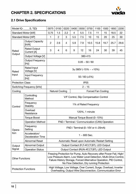
CHAPTER 2. SPECIFICATIONS
2.1 Drive Specifications
Model IQ-_____S, T(D) 0075 0150 0220 0400 0550 0750 1100 1500 1850 2200
Standard Motor [kW] 0.75 1.5 2.2 4 5.5 7.5 11 15 18.5 22
Standard Motor [HP] 1 2 3 5.5 7.5 10 15 20 25 30
Rated Output
Output Capacity [kVA]
2 2.6 4 5.9 7.9 10.5 15.8 19.7 25.7 29.6
Rated OutputCurrent [A]
3 4 6 9 12 16 24 30 39 45
Output Voltage [V] 380-415
Output Frequency [Hz]
0.05 ~ 50 / 60
Rated Input
Rated Input Voltage [V]
3φ 380V (-15% ~ +10%)
Input Frequency [Hz]
50 / 60 (±5%)
Protection Class IP55
Switching Frequency [kHz] 2 ~ 15
Cooling Natural Cooling Forced Fan Cooling
Control
Controlling Method
V/F Control, Slip Compensation Control
Frequency Stability
1% of Rated Frequency
Overload Resistance
120%, 1 minute
Torque Boost Manual Torque Boost (0~10%)
Opera-tion
Operation Method FND / Terminal / Communication (CAN) Operation
Frequency Setting
FND / Terminal (0~10V or 4~20mA)
Acceleration/ Deceleration Time
1 ~ 600 Sec.
Abnormal Reset Automatic Reset upon Automatic Restart Setting
Output Signal
Abnormal Output Output Contact (FLT-AT,CT,BT), LED Output
Operation Status Output Contact (RUN-AT,CT,BT), LED Output
Other Functions
Freezing Protection for Pump, Auto Recovery after Power Fail, High/Low Pressure Alarm, Low Water Level Detection, Multi-Drive Control,
Failure History Storage, Forced Alternative Operation, PID Control, No Flow Detection, Dry running Protection
Protection FunctionsHigh Voltage, Low Voltage, Over Current, Surge, Overload, Inverter
Overheating, Output Wire Disconnection, Communication Error
│ 11
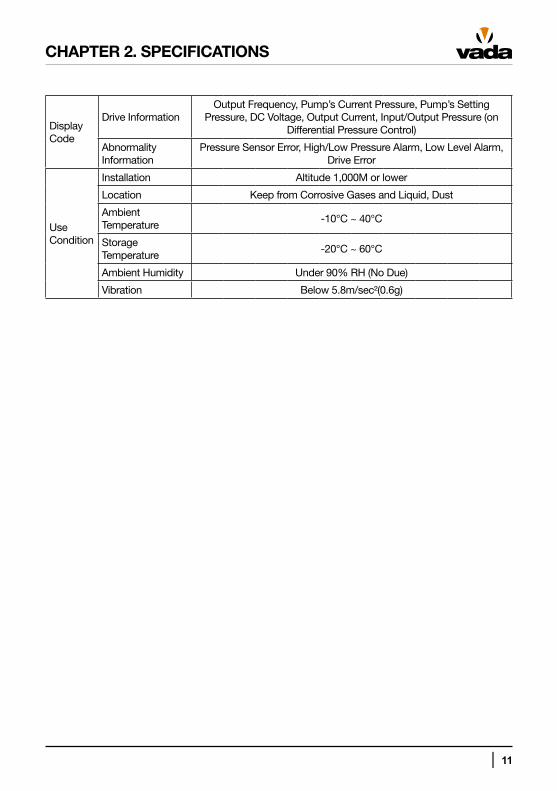
Display Code
Drive InformationOutput Frequency, Pump’s Current Pressure, Pump’s Setting
Pressure, DC Voltage, Output Current, Input/Output Pressure (on Differential Pressure Control)
Abnormality Information
Pressure Sensor Error, High/Low Pressure Alarm, Low Level Alarm, Drive Error
Use Condition
Installation Altitude 1,000M or lower
Location Keep from Corrosive Gases and Liquid, Dust
Ambient Temperature
-10°C ~ 40°C
Storage Temperature
-20°C ~ 60°C
Ambient Humidity Under 90% RH (No Due)
Vibration Below 5.8m/sec²(0.6g)
CHAPTER 2. SPECIFICATIONS
12 │
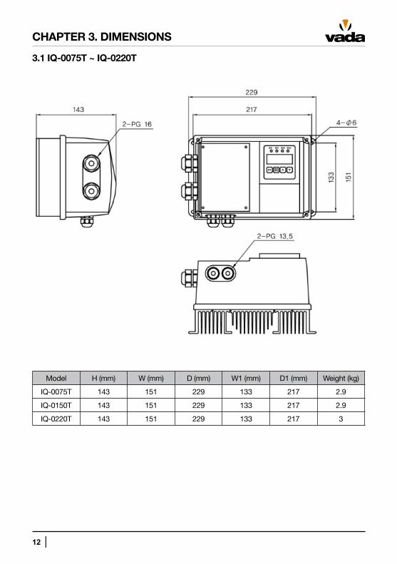
CHAPTER 3. DIMENSIONS
3.1 IQ-0075T ~ IQ-0220T
Model H (mm) W (mm) D (mm) W1 (mm) D1 (mm) Weight (kg)
IQ-0075T 143 151 229 133 217 2.9
IQ-0150T 143 151 229 133 217 2.9
IQ-0220T 143 151 229 133 217 3
│ 13
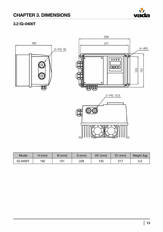
3.2 IQ-0400T
CHAPTER 3. DIMENSIONS
Model H (mm) W (mm) D (mm) W1 (mm) D1 (mm) Weight (kg)
IQ-0400T 162 151 229 133 217 3.3
14 │
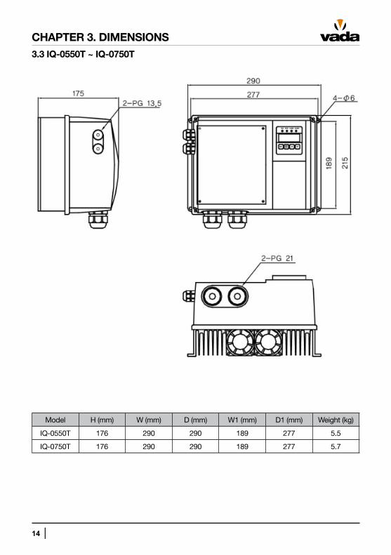
3.3 IQ-0550T ~ IQ-0750T
CHAPTER 3. DIMENSIONS
Model H (mm) W (mm) D (mm) W1 (mm) D1 (mm) Weight (kg)
IQ-0550T 176 290 290 189 277 5.5
IQ-0750T 176 290 290 189 277 5.7
│ 15
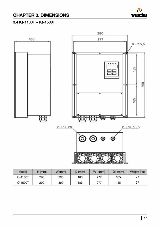
3.4 IQ-1100T ~ IQ-1500T
CHAPTER 3. DIMENSIONS
Model H (mm) W (mm) D (mm) W1 (mm) D1 (mm) Weight (kg)
IQ-1100T 290 390 186 277 185 27
IQ-1500T 290 390 186 277 185 27
16 │
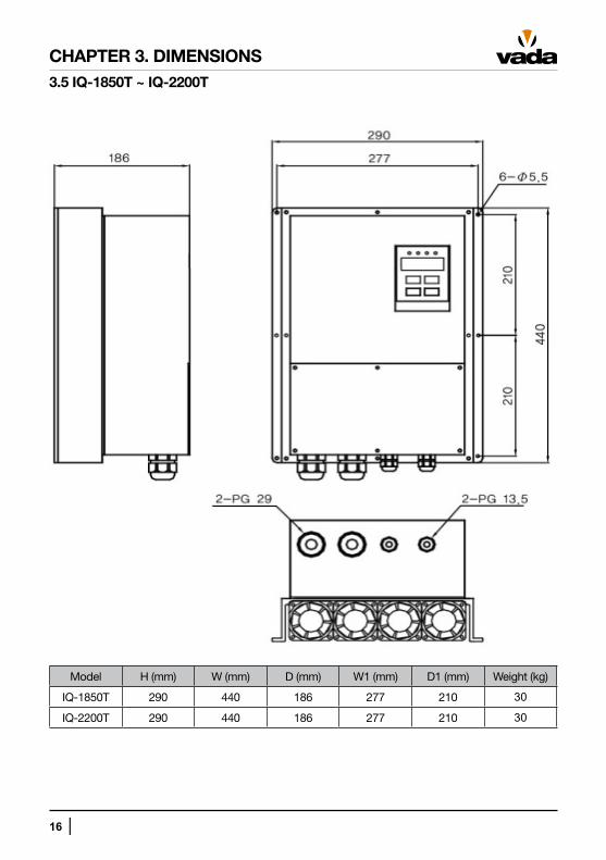
3.5 IQ-1850T ~ IQ-2200T
CHAPTER 3. DIMENSIONS
Model H (mm) W (mm) D (mm) W1 (mm) D1 (mm) Weight (kg)
IQ-1850T 290 440 186 277 210 30
IQ-2200T 290 440 186 277 210 30
│ 17
CHAPTER 4. INSTALLATION
4.1 Installation Precautions
A. Take care when handling
Drive consists of sensitive electric/electronic devices. Take care to prevent damage due to rough
handling during transportation and installation.
B. Minimize Vibration
Drive is susceptible to damage due to excessive vibration. If mounting drive directly onto motor or
piping, take measures to prevent damage due to excessive vibration.
C. Caution: Ambient Temperature
The drive has an allowable ambient temperature range of between -10 ~ 40ºC. If ambient
temperature exceeds these limits, reduce the output rating of the drive before use.
D. Install on non-flammable/ incombustible materials
The drive will generate heat and become hot during operation. To minimise fire hazards, mount the
drive on non-flammable/ incombustible materials.
E. Allow sufficient space for effective cooling
Install drive ensuring that air flow to the cooling fins is not obstructed
F. If the drive is installed off the motor, install the drive securely in upright position.
18 │
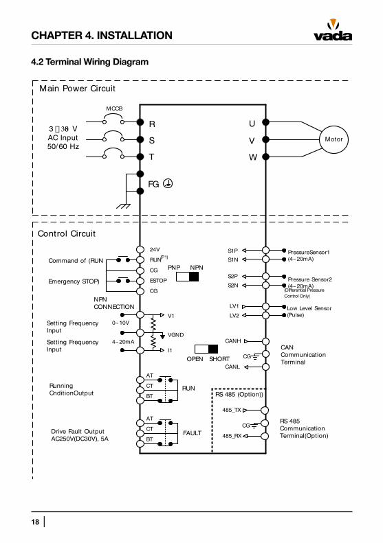
4.2 Terminal Wiring Diagram
CHAPTER 4. INSTALLATION
MCCB
3 � 380 VAC Input 50/60 Hz
Main Power Circuit
S
T
U
V
W
FG
Motor
S1P
S1N
S2P
S2N
PressureSensor1(4~20mA)
Pressure Sensor2 (4~20mA)
LV1
LV2Low Level Sensor (Pulse)
CANH
CG
CANL
1
BT
Control Circuit
R
CAN Communication Terminal
Running CnditionOutput
V1
VGND
I1
4~20mA
0~10V
AT
CT
BT
AT
CT
RUN
FAULT
Command of (RUN
CG
ESTOP
RUN
CG
24V
Emergency STOP)
Setting Frequency Input
Setting Frequency Input
Drive Fault OutputAC250V(DC30V), 5A
485_TX
CG
485_RX
RS 485 CommunicationTerminal(Option)
RS 485 (Option))
NPN CONNECTION
NPNPNP
SHORTOPEN
(Differential Pressure Control Only)
(P1)
│ 19
CHAPTER 4. INSTALLATION
4.3 Main Power Supply Circuit Wiring
Main Power Supply Terminals
Terminal Name Description
R, S, T AC Input Connect to commercial AC input
FG Earth Connect to earth
U, V, W Drive Output Connect to Motor
Precautions on Main Power Supply Wiring
• Ensure power supply is disconnected and there is no residual charge in drive (<30V)
• Install circuit breaker (MCCB) between AC input power and drive input power terminals (R, S, T). Use a circuit breaker with a capacity 1.5 ~ 2 times larger than the rated current.
• EMI can occur due to the high speed switching of the drive and can cause radio interference on nearby electrical equipment. In order to minimise radio interference, install EMC filters between
• AC power input and the drive where required.
• AC input terminals (R, S, T) can be connected regardless of phase sequence of input power.
• When connecting output terminals of the drive to the input terminals of the motor, consider the rotation direction of the motor. In order to reverse the direction of the motor swap any two of the drive terminals (U, V, W). May also be altered through programming.
• In order to prevent damage to the drive, take care not to short circuit or earth the drive output terminals (U, V ,W).
• Do not connect static condenser or noise filter at the output of the drive as it may cause the drive to frequently trip. This may result in damage to the devices due to overheating.
• Use wires of the specified size for the drive input/output. Failure to use wires of appropriate size may result in a reduction in voltage and may result in a fire hazard due to overheating.
• Maintain wiring distance between motor and drive less than 50 metres. If drive is installed further away than this, use a motor with reinforced insulation or micro-surge filter.
Precautions on Earth Wiring
• A leak current is produced from the high speed switching of the drive so an earth connection is required to prevent electric shock.
• Maintain earth resistance within 10Ω during earthing work.
• Use wire tas shown in the table below for the earth connection.
20 │
CHAPTER 4. INSTALLATION
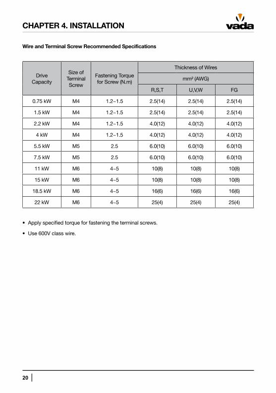
Wire and Terminal Screw Recommended Specifications
Drive Capacity
Size of Terminal Screw
Fastening Torque for Screw (N.m)
Thickness of Wires
mm² (AWG)
R,S,T U,V,W FG
0.75 kW M4 1.2~1.5 2.5(14) 2.5(14) 2.5(14)
1.5 kW M4 1.2~1.5 2.5(14) 2.5(14) 2.5(14)
2.2 kW M4 1.2~1.5 4.0(12) 4.0(12) 4.0(12)
4 kW M4 1.2~1.5 4.0(12) 4.0(12) 4.0(12)
5.5 kW M5 2.5 6.0(10) 6.0(10) 6.0(10)
7.5 kW M5 2.5 6.0(10) 6.0(10) 6.0(10)
11 kW M6 4~5 10(8) 10(8) 10(8)
15 kW M6 4~5 10(8) 10(8) 10(8)
18.5 kW M6 4~5 16(6) 16(6) 16(6)
22 kW M6 4~5 25(4) 25(4) 25(4)
• Apply specified torque for fastening the terminal screws.
• Use 600V class wire.
│ 21
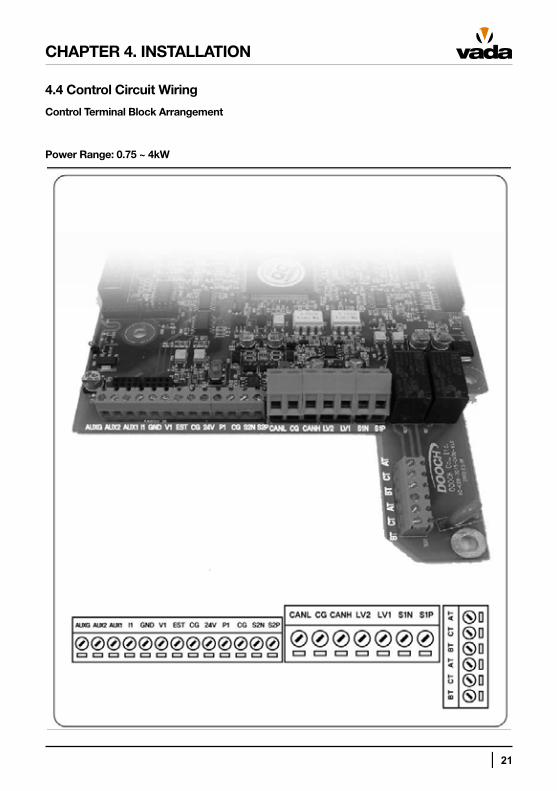
4.4 Control Circuit Wiring
Control Terminal Block Arrangement
Power Range: 0.75 ~ 4kW
CHAPTER 4. INSTALLATION
22 │
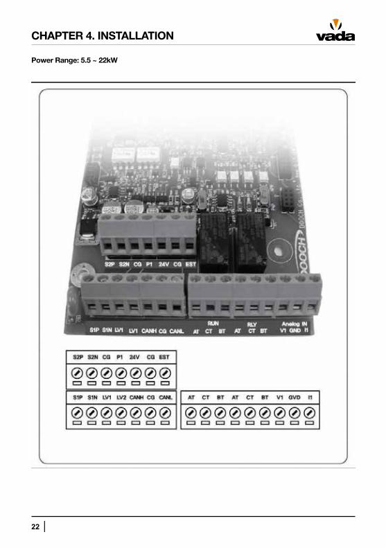
Power Range: 5.5 ~ 22kW
CHAPTER 4. INSTALLATION
│ 23
CHAPTER 4. INSTALLATION
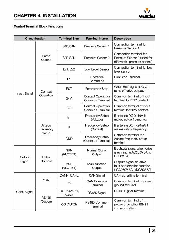
Control Terminal Block Functions
Classification Terminal Sign Terminal Name Description
Input Signal
Pump Control
S1P, S1N Pressure Sensor 1Connection terminal for Pressure Sensor 1
S2P, S2N Pressure Sensor 2Connection terminal for Pressure Sensor 2 (used for differential pressure control)
LV1, LV2 Low Level SensorConnection terminal for low level sensor
Contact Operation
P1Operation Command
Run/Stop Terminal
EST Emergency StopWhen EST signal is ON, it turns off drive output.
24VContact Operation Common Terminal
Common terminal of input terminal for PNP contact.
CGContact Operation Common Terminal
Common terminal of input terminal for NPN contact.
Analog Frequency
Setup
V1Frequency Setup
(Voltage)If entering DC 0~10V, it makes setup frequency.
I1Frequency Setup
(Current)If entering DC 4~20mA it makes setup frequency.
GNDFrequency Setup
(Common Terminal)
Common terminal for Analog frequency setup terminal
Output Signal
Relay Contact
RUN (AT,CT,BT)
Normal Signal Output
It outputs signal when drive is running. (≤AC250V 5A, ≤ DC30V 5A)
FAULT (AT,CT,BT)
Multi-function Output
Outputs signal on drive fault or protection function. (≤AC250V 5A, ≤DC30V 5A)
Com. Signal
CAN
CANH, CANL CAN Signal CAN signal line terminal
CGCAN Common
TerminalCommon terminal of power ground for CAN
RS485 (Option)
TX, RX (AUX1, AUX2)
RS485 SignalRS485 Signal Terminal
CG (AUXG)RS485 Common
Terminal
Common terminal of power ground for RS485 communication
24 │
CHAPTER 4. INSTALLATION
Control Circuit Wiring Precautions
• Maintain wiring distance between pressure sensor and drive within 10 metres.
• If using a remote control with analogue signals, maintain distance between remote and drive within 50 metres.
• Separate sensor and analogue signal wires away from power wires.
• Use shielded twisted wires for signal lines of control circuit.
• GND and CG are insulated from each other. Do not connect them together.
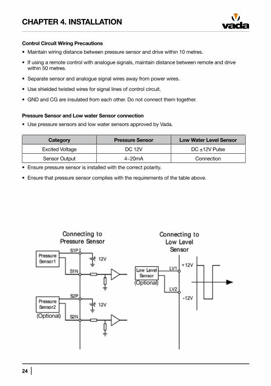
Pressure Sensor and Low water Sensor connection
• Use pressure sensors and low water sensors approved by Vada.
Category Pressure Sensor Low Water Level Sensor
Excited Voltage DC 12V DC ±12V Pulse
Sensor Output 4~20mA Connection
• Ensure pressure sensor is installed with the correct polarity.
• Ensure that pressure sensor complies with the requirements of the table above.
(Optional)
(Optional)
│ 25
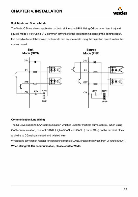
Sink Mode and Source Mode
The Vada IQ Drive allows application of both sink mode (NPN: Using CG common terminal) and
source mode (PNP: Using 24V common terminal) to the input terminal logic of the control circuit.
It is possible to switch between sink mode and source mode using the selection switch within the
control board.
Communication Line Wiring
The IQ Drive supports CAN communication which is used for multiple pump control. When using
CAN communication, connect CANH (High of CAN) and CANL (Low of CAN) on the terminal block
and wire to CG using shielded and twisted wire.
When using termination resistor for connecting multiple CANs, change the switch from OPEN to SHORT.
When Using RS 485 communication, please contact Vada.
CHAPTER 4. INSTALLATION
SinkMode (NPN)
SourceMode (PNP)
26 │
CHAPTER 5. OPERATION
5.1 Function Display (FND)
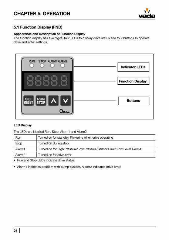
Appearance and Description of Function DisplayThe function display has five digits, four LEDs to display drive status and four buttons to operate drive and enter settings.
LED Display
The LEDs are labelled Run, Stop, Alarm1 and Alarm2.
Run Turned on for standby. Flickering when drive operating
Stop Turned on during stop.
Alarm1 Turned on for High Pressure/Low Pressure/Sensor Error/ Low Level Alarms
Alarm2 Turned on for drive error
• Run and Stop LEDs indicate drive status.
• Alarm1 indicates problem with pump system. Alarm2 indicates drive error.
Indicator LEDs
Function Display
Buttons
│ 27
Digital Display
The digital display consists of five digits and displays parameter setting and status values of the
drive and pump. Displays are divided in St group (Status Group), Pr group (Pump Control Group)
and dr group (Drive Group).
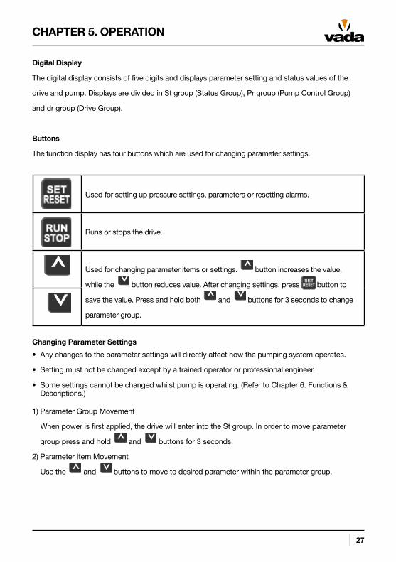
Buttons
The function display has four buttons which are used for changing parameter settings.
CHAPTER 5. OPERATION
Used for setting up pressure settings, parameters or resetting alarms.
Runs or stops the drive.
Used for changing parameter items or settings. button increases the value,
while the button reduces value. After changing settings, press button to
save the value. Press and hold both and buttons for 3 seconds to change
parameter group.
Changing Parameter Settings
• Any changes to the parameter settings will directly affect how the pumping system operates.
• Setting must not be changed except by a trained operator or professional engineer.
• Some settings cannot be changed whilst pump is operating. (Refer to Chapter 6. Functions & Descriptions.)
1) Parameter Group Movement
When power is first applied, the drive will enter into the St group. In order to move parameter
group press and hold and buttons for 3 seconds.
2) Parameter Item Movement
Use the and buttons to move to desired parameter within the parameter group.
28 │
CHAPTER 5. OPERATION
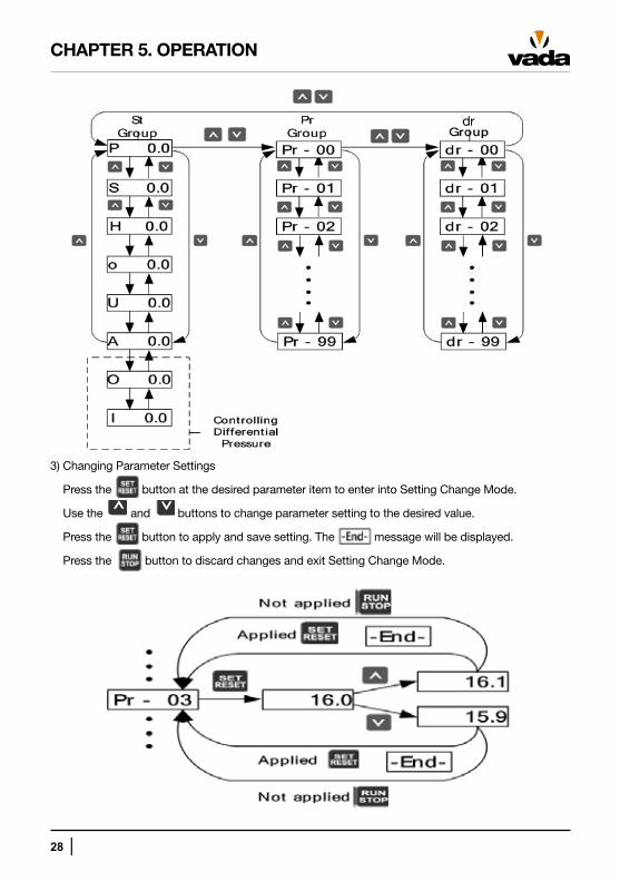
3) Changing Parameter Settings
Press the button at the desired parameter item to enter into Setting Change Mode.
Use the and buttons to change parameter setting to the desired value.
Press the button to apply and save setting. The message will be displayed.
Press the button to discard changes and exit Setting Change Mode.
dr
│ 29
CHAPTER 5. OPERATION
5.2 Function Setup
Basic Function Setup
Any parameter that is not set by the user will be set to the factory default setting.
1) Common Setup
These parameters are used to setup drive when controlling pump regardless of type of control.
Setup ItemParameter
CodeDescription
Input Location of Run Command dr-01To select a method to issue Run command (FND, Terminal Block)
Input Method of Target Frequency dr-02To select a method to control target operation frequency (Own PID, FND, V1, I1)
Capacity of Motor dr-10 To set up Capacity of Motor
No. of Poles of Motor dr-11 To set up No. of Poles of Motor
Rated Current of Motor dr-12 To set up Rated Current of Motor
Rated Rotations of Motor dr-13 To set up Rated Rotations of Motor
Rated Voltage of Motor dr-14 To set up Rated Voltage of Motor
No-load Current of Motor dr-15 To set up No-load Current of Motor
Rated Slip Frequency of Motor dr-16 To set up Rated Slip Frequency of Motor
Rated Frequency of Motor dr-17 To set up Rated Frequency of Motor
Efficiency of Motor dr-18 To set up Efficiency of Motor
Rotation Direction Selection of Motor dr-20To set up Rotation Direction Selection of Motor Properly
Stopping Method of Motor dr-21To set up Stopping Method of Motor to stop the motor
30 │
CHAPTER 5. OPERATION
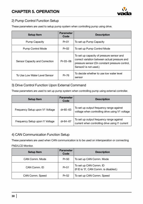
2) Pump Control Function Setup
These parameters are used to setup pump system when controlling pump using drive.
Setup ItemParameter
CodeDescription
Pump Capacity Pr-01 To set up Pump Capacity
Pump Control Mode Pr-02 To set up Pump Control Mode
Sensor Capacity and Correction Pr-03~06
To set up capacity of pressure sensor and correct variation between actual pressure and pressure sensor (On constant pressure control, Sensor2 is not used.)
To Use Low Water Level Sensor Pr-76To decide whether to use low water level sensor
3) Drive Control Function Upon External Command
These parameters are used to set up pump system when controlling pump using external controller.
Setup ItemParameter
CodeDescription
Frequency Setup upon V1 Voltage dr-60~63To set up output frequency range against voltage when controlling drive using V1 voltage
Frequency Setup upon I1 Voltage dr-64~67To set up output frequency range against current when controlling drive using I1 current
4) CAN Communication Function Setup
These parameters are used when CAN communication is to be used on interoperation or connecting
FND/LCD Monitor.
Setup ItemParameter
CodeDescription
CAN Comm. Mode Pr-50 To set up CAN Comm. Mode
CAN Comm. ID Pr-51To set up CAN Comm. ID (If ID is ‘0’, CAN Comm. is disabled.)
CAN Comm. Speed Pr-52 To set up CAN Comm. Speed
│ 31
CHAPTER 5. OPERATION
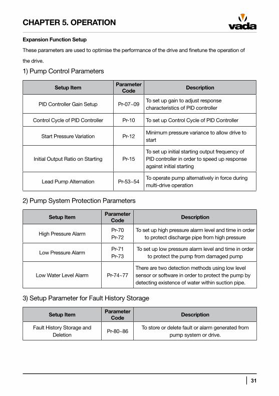
Expansion Function Setup
These parameters are used to optimise the performance of the drive and finetune the operation of
the drive.
1) Pump Control Parameters
Setup ItemParameter
CodeDescription
PID Controller Gain Setup Pr-07~09To set up gain to adjust response characteristics of PID controller
Control Cycle of PID Controller Pr-10 To set up Control Cycle of PID Controller
Start Pressure Variation Pr-12Minimum pressure variance to allow drive to start
Initial Output Ratio on Starting Pr-15To set up initial starting output frequency of PID controller in order to speed up response against initial starting
Lead Pump Alternation Pr-53~54To operate pump alternatively in force during multi-drive operation
2) Pump System Protection Parameters
Setup ItemParameter
CodeDescription
High Pressure AlarmPr-70Pr-72
To set up high pressure alarm level and time in order to protect discharge pipe from high pressure
Low Pressure AlarmPr-71Pr-73
To set up low pressure alarm level and time in order to protect the pump from damaged pump
Low Water Level Alarm Pr-74~77There are two detection methods using low level sensor or software in order to protect the pump by detecting existence of water within suction pipe.
3) Setup Parameter for Fault History Storage
Setup ItemParameter
CodeDescription
Fault History Storage and Deletion
Pr-80~86To store or delete fault or alarm generated from
pump system or drive.
32 │
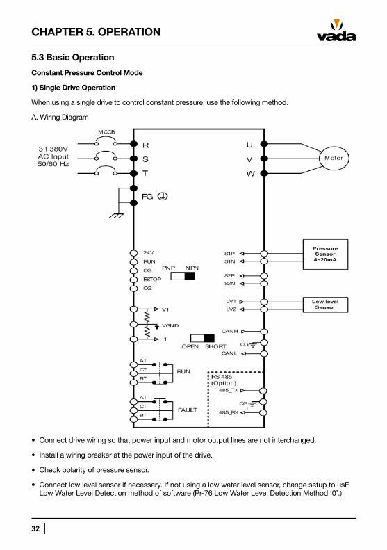
5.3 Basic Operation
Constant Pressure Control Mode
1) Single Drive Operation
When using a single drive to control constant pressure, use the following method.
A. Wiring Diagram
• Connect drive wiring so that power input and motor output lines are not interchanged.
• Install a wiring breaker at the power input of the drive.
• Check polarity of pressure sensor.
• Connect low level sensor if necessary. If not using a low water level sensor, change setup to usE Low Water Level Detection method of software (Pr-76 Low Water Level Detection Method ‘0’.)
CHAPTER 5. OPERATION
│ 33
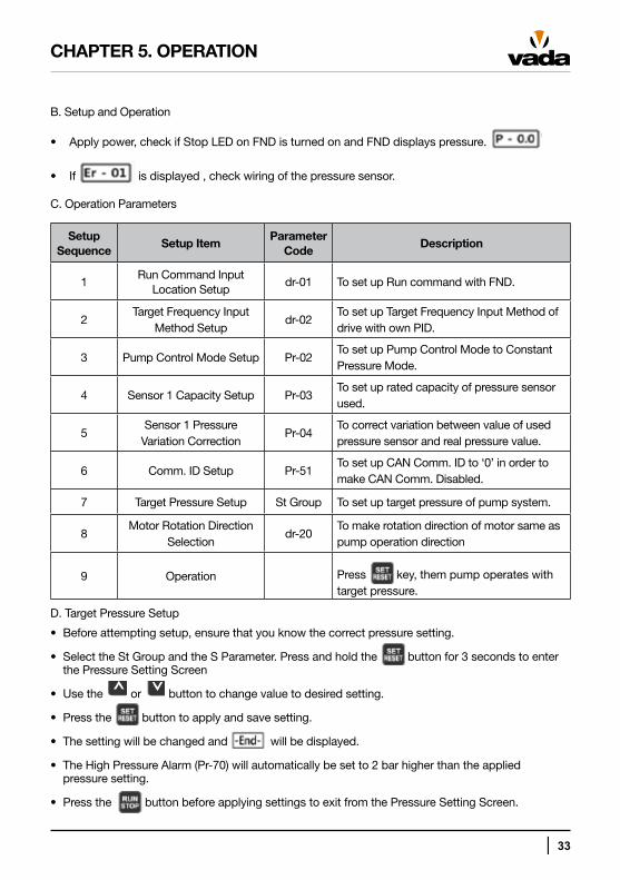
B. Setup and Operation
• ● Apply power, check if Stop LED on FND is turned on and FND displays pressure.
• ● If is displayed , check wiring of the pressure sensor.
C. Operation Parameters
Setup Sequence
Setup ItemParameter
CodeDescription
1Run Command Input
Location Setupdr-01 To set up Run command with FND.
2Target Frequency Input
Method Setupdr-02
To set up Target Frequency Input Method of drive with own PID.
3 Pump Control Mode Setup Pr-02To set up Pump Control Mode to Constant Pressure Mode.
4 Sensor 1 Capacity Setup Pr-03To set up rated capacity of pressure sensor used.
5Sensor 1 Pressure
Variation CorrectionPr-04
To correct variation between value of used pressure sensor and real pressure value.
6 Comm. ID Setup Pr-51To set up CAN Comm. ID to ‘0’ in order to make CAN Comm. Disabled.
7 Target Pressure Setup St Group To set up target pressure of pump system.
8Motor Rotation Direction
Selectiondr-20
To make rotation direction of motor same as pump operation direction
9 Operation Press key, them pump operates with target pressure.
D. Target Pressure Setup
• Before attempting setup, ensure that you know the correct pressure setting.
• Select the St Group and the S Parameter. Press and hold the button for 3 seconds to enter the Pressure Setting Screen
• Use the or button to change value to desired setting.
• Press the button to apply and save setting.
• The setting will be changed and will be displayed.
• The High Pressure Alarm (Pr-70) will automatically be set to 2 bar higher than the applied pressure setting.
• Press the button before applying settings to exit from the Pressure Setting Screen.
CHAPTER 5. OPERATION
34 │
E. Pump Rotation Direction
• The default rotation direction is counter clockwise.
• In order to change rotation direction use one of the following methods:
1. Switch two of the three motor power input wires.
2. Change the value of the Motor Rotation Direction parameter (dr-20).
CHAPTER 5. OPERATION
│ 35
CHAPTER 5. OPERATION
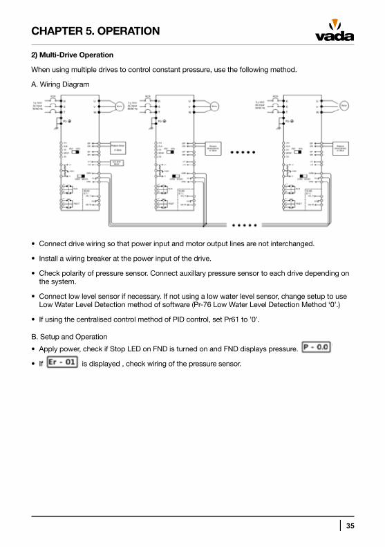
2) Multi-Drive Operation
When using multiple drives to control constant pressure, use the following method.
A. Wiring Diagram
• Connect drive wiring so that power input and motor output lines are not interchanged.
• Install a wiring breaker at the power input of the drive.
• Check polarity of pressure sensor. Connect auxillary pressure sensor to each drive depending on the system.
• Connect low level sensor if necessary. If not using a low water level sensor, change setup to use Low Water Level Detection method of software (Pr-76 Low Water Level Detection Method ‘0’.)
• If using the centralised control method of PID control, set Pr61 to ’0’.
B. Setup and Operation
• Apply power, check if Stop LED on FND is turned on and FND displays pressure.
• If is displayed , check wiring of the pressure sensor.
36 │
CHAPTER 5. OPERATION
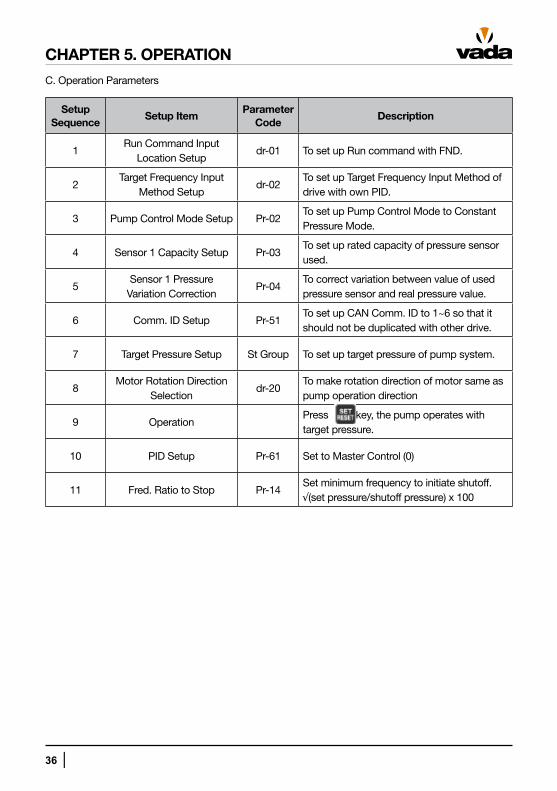
C. Operation Parameters
Setup Sequence
Setup ItemParameter
CodeDescription
1Run Command Input
Location Setupdr-01 To set up Run command with FND.
2Target Frequency Input
Method Setupdr-02
To set up Target Frequency Input Method of drive with own PID.
3 Pump Control Mode Setup Pr-02To set up Pump Control Mode to Constant Pressure Mode.
4 Sensor 1 Capacity Setup Pr-03To set up rated capacity of pressure sensor used.
5Sensor 1 Pressure
Variation CorrectionPr-04
To correct variation between value of used pressure sensor and real pressure value.
6 Comm. ID Setup Pr-51To set up CAN Comm. ID to 1~6 so that it should not be duplicated with other drive.
7 Target Pressure Setup St Group To set up target pressure of pump system.
8Motor Rotation Direction
Selectiondr-20
To make rotation direction of motor same as pump operation direction
9 OperationPress key, the pump operates with target pressure.
10 PID Setup Pr-61 Set to Master Control (0)
11 Fred. Ratio to Stop Pr-14Set minimum frequency to initiate shutoff.√(set pressure/shutoff pressure) x 100
│ 37
CHAPTER 5. OPERATION
D. Pump Rotation Direction
• The default rotation direction is counter clockwise.
• In order to change rotation direction use one of the following methods:
1. Switch two of the three power input wires.
2. Change the value of the Motor Rotation Direction parameter (dr-20).
D. Target Pressure Setup
• Before attempting setup, ensure that you know the correct pressure setting.
• If using linked drive operation, setup pressure on one drive will be automatically set on all drives through CAN communication.
• Select the St Group and the S Parameter. Press and hold the button for 3 seconds to enter the Pressure Setting Screen
• Use the or button to change value to desired setting.
• Press the button to apply and save setting.
• The setting will be changed and will be displayed.
• The High Pressure Alarm (Pr-70) will automatically be set to 2 bar higher than the applied pressure setting.
• If you press the button before pressing the button the setting will not be changed.
38 │
CHAPTER 6. FUNCTION TABLE & DESCRIPTION
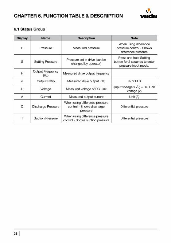
6.1 Status Group
Display Name Description Note
P Pressure Measured pressureWhen using difference
pressure control - Shows difference pressure
S Setting PressurePressure set in drive (can be
changed by operator)
Press and hold Setting button for 2 seconds to enter
pressure input mode.
HOutput Frequency
(Hz)Measured drive output frequency
o Output Ratio Measured drive output (%) % of FLS
U Voltage Measured voltage of DC Link(Input voltage x √2) = DC Link
voltage (V)
A Current Measured output current Unit (A)
O Discharge PressureWhen using difference pressure
control - Shows discharge pressure
Differential pressure
I Suction PressureWhen using difference pressure
control - Shows suction pressureDifferential pressure
│ 39
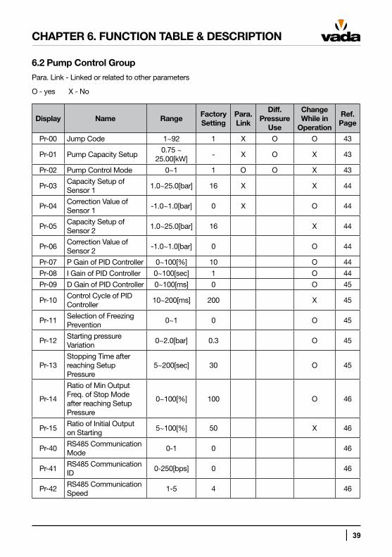
6.2 Pump Control Group
Para. Link - Linked or related to other parameters
O - yes X - No
Display Name RangeFactory Setting
Para. Link
Diff. Pressure
Use
Change While in
Operation
Ref. Page
Pr-00 Jump Code 1~92 1 X O O 43
Pr-01 Pump Capacity Setup0.75 ~
25.00[kW]- X O X 43
Pr-02 Pump Control Mode 0~1 1 O O X 43
Pr-03Capacity Setup of Sensor 1
1.0~25.0[bar] 16 X ● X 44
Pr-04Correction Value of Sensor 1
-1.0~1.0[bar] 0 X ● O 44
Pr-05Capacity Setup of Sensor 2
1.0~25.0[bar] 16 ● ● X 44
Pr-06Correction Value of Sensor 2
-1.0~1.0[bar] 0 ● ● O 44
Pr-07 P Gain of PID Controller 0~100[%] 10 ● ● O 44
Pr-08 I Gain of PID Controller 0~100[sec] 1 ● ● O 44
Pr-09 D Gain of PID Controller 0~100[ms] 0 ● ● O 45
Pr-10Control Cycle of PID Controller
10~200[ms] 200 ● ● X 45
Pr-11Selection of Freezing Prevention
0~1 0 ● ● O 45
Pr-12Starting pressure Variation
0~2.0[bar] 0.3 ● ● O 45
Pr-13Stopping Time after reaching Setup Pressure
5~200[sec] 30 ● ● O 45
Pr-14
Ratio of Min Output Freq. of Stop Mode after reaching Setup Pressure
0~100[%] 100 ● ● O 46
Pr-15Ratio of Initial Output on Starting
5~100[%] 50 ● ● X 46
Pr-40RS485 Communication Mode
0-1 0 ● ● ● 46
Pr-41RS485 Communication ID
0-250[bps] 0 ● ● ● 46
Pr-42RS485 Communication Speed
1-5 4 ● ● ● 46
CHAPTER 6. FUNCTION TABLE & DESCRIPTION
40 │
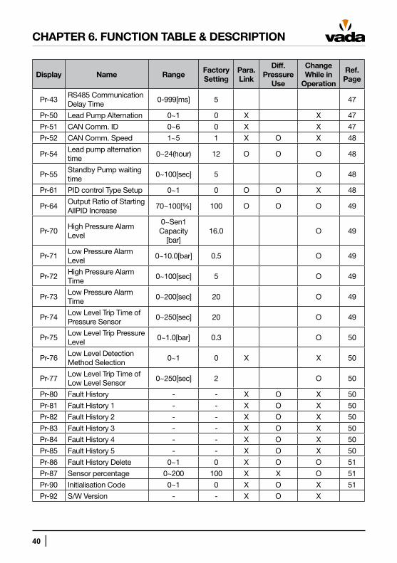
Display Name RangeFactory Setting
Para. Link
Diff. Pressure
Use
Change While in
Operation
Ref. Page
Pr-43RS485 Communication Delay Time
0-999[ms] 5 ● ● ● 47
Pr-50 Lead Pump Alternation 0~1 0 X ● X 47
Pr-51 CAN Comm. ID 0~6 0 X ● X 47
Pr-52 CAN Comm. Speed 1~5 1 X O X 48
Pr-54Lead pump alternation time
0~24(hour) 12 O O O 48
Pr-55Standby Pump waiting time
0~100[sec] 5 ● ● O 48
Pr-61 PID control Type Setup 0~1 0 O O X 48
Pr-64Output Ratio of Starting AllPID Increase
70~100[%] 100 O O O 49
Pr-70High Pressure Alarm Level
0~Sen1 Capacity
[bar]16.0 ● ● O 49
Pr-71Low Pressure Alarm Level
0~10.0[bar] 0.5 ● ● O 49
Pr-72High Pressure Alarm Time
0~100[sec] 5 ● ● O 49
Pr-73Low Pressure Alarm Time
0~200[sec] 20 ● ● O 49
Pr-74Low Level Trip Time of Pressure Sensor
0~250[sec] 20 ● ● O 49
Pr-75Low Level Trip Pressure Level
0~1.0[bar] 0.3 ● ● O 50
Pr-76Low Level Detection Method Selection
0~1 0 X ● X 50
Pr-77Low Level Trip Time of Low Level Sensor
0~250[sec] 2 ● ● O 50
Pr-80 Fault History - - X O X 50
Pr-81 Fault History 1 - - X O X 50
Pr-82 Fault History 2 - - X O X 50
Pr-83 Fault History 3 - - X O X 50
Pr-84 Fault History 4 - - X O X 50
Pr-85 Fault History 5 - - X O X 50
Pr-86 Fault History Delete 0~1 0 X O O 51
Pr-87 Sensor percentage 0~200 100 X X O 51
Pr-90 Initialisation Code 0~1 0 X O X 51
Pr-92 S/W Version - - X O X
CHAPTER 6. FUNCTION TABLE & DESCRIPTION
│ 41
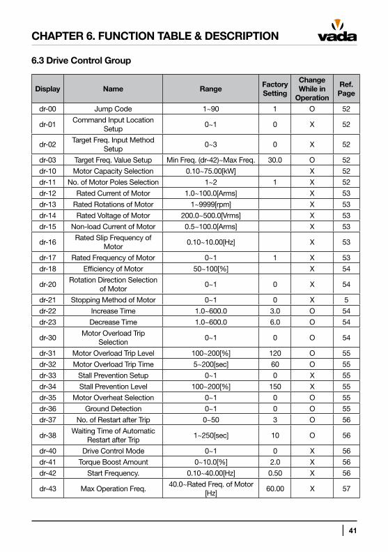
6.3 Drive Control Group
Display Name RangeFactory Setting
Change While in
Operation
Ref. Page
dr-00 Jump Code 1~90 1 O 52
dr-01Command Input Location
Setup0~1 0 X 52
dr-02Target Freq. Input Method
Setup0~3 0 X 52
dr-03 Target Freq. Value Setup Min Freq. (dr-42)~Max Freq. 30.0 O 52
dr-10 Motor Capacity Selection 0.10~75.00[kW] X 52
dr-11 No. of Motor Poles Selection 1~2 1 X 52
dr-12 Rated Current of Motor 1.0~100.0[Arms] X 53
dr-13 Rated Rotations of Motor 1~9999[rpm] X 53
dr-14 Rated Voltage of Motor 200.0~500.0[Vrms] X 53
dr-15 Non-load Current of Motor 0.5~100.0[Arms] X 53
dr-16Rated Slip Frequency of
Motor0.10~10.00[Hz] X 53
dr-17 Rated Frequency of Motor 0~1 1 X 53
dr-18 Efficiency of Motor 50~100[%] X 54
dr-20Rotation Direction Selection
of Motor0~1 0 X 54
dr-21 Stopping Method of Motor 0~1 0 X 5
dr-22 Increase Time 1.0~600.0 3.0 O 54
dr-23 Decrease Time 1.0~600.0 6.0 O 54
dr-30Motor Overload Trip
Selection0~1 0 O 54
dr-31 Motor Overload Trip Level 100~200[%] 120 O 55
dr-32 Motor Overload Trip Time 5~200[sec] 60 O 55
dr-33 Stall Prevention Setup 0~1 0 X 55
dr-34 Stall Prevention Level 100~200[%] 150 X 55
dr-35 Motor Overheat Selection 0~1 0 O 55
dr-36 Ground Detection 0~1 0 O 55
dr-37 No. of Restart after Trip 0~50 3 O 56
dr-38Waiting Time of Automatic
Restart after Trip1~250[sec] 10 O 56
dr-40 Drive Control Mode 0~1 0 X 56
dr-41 Torque Boost Amount 0~10.0[%] 2.0 X 56
dr-42 Start Frequency. 0.10~40.00[Hz] 0.50 X 56
dr-43 Max Operation Freq.40.0~Rated Freq. of Motor
[Hz]60.00 X 57
CHAPTER 6. FUNCTION TABLE & DESCRIPTION
42 │
Display Name RangeFactory Setting
Change While in
Operation
Ref. Page
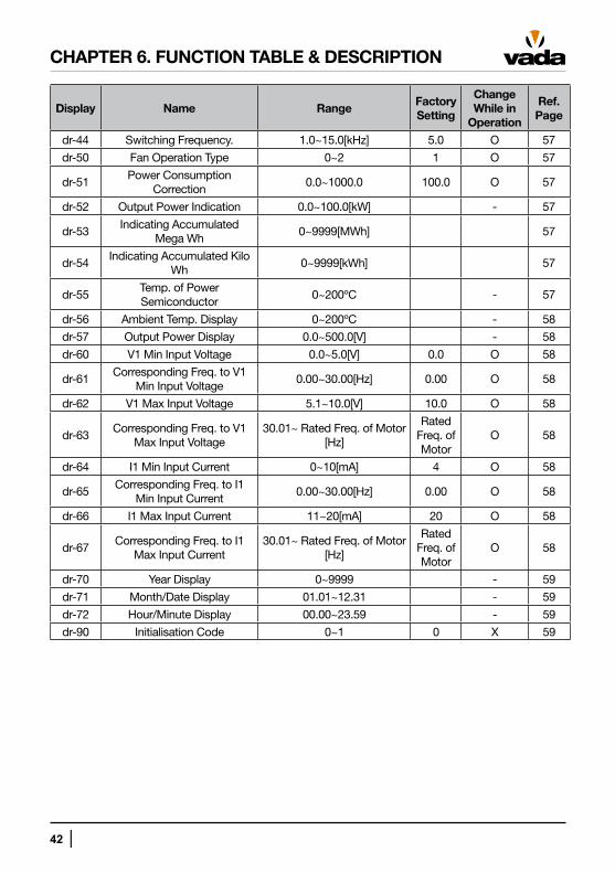
dr-44 Switching Frequency. 1.0~15.0[kHz] 5.0 O 57
dr-50 Fan Operation Type 0~2 1 O 57
dr-51Power Consumption
Correction0.0~1000.0 100.0 O 57
dr-52 Output Power Indication 0.0~100.0[kW] - 57
dr-53Indicating Accumulated
Mega Wh0~9999[MWh] 57
dr-54Indicating Accumulated Kilo
Wh0~9999[kWh] 57
dr-55Temp. of Power Semiconductor
0~200ºC - 57
dr-56 Ambient Temp. Display 0~200ºC - 58
dr-57 Output Power Display 0.0~500.0[V] - 58
dr-60 V1 Min Input Voltage 0.0~5.0[V] 0.0 O 58
dr-61Corresponding Freq. to V1
Min Input Voltage0.00~30.00[Hz] 0.00 O 58
dr-62 V1 Max Input Voltage 5.1~10.0[V] 10.0 O 58
dr-63Corresponding Freq. to V1
Max Input Voltage30.01~ Rated Freq. of Motor
[Hz]
Rated Freq. of Motor
O 58
dr-64 I1 Min Input Current 0~10[mA] 4 O 58
dr-65Corresponding Freq. to I1
Min Input Current0.00~30.00[Hz] 0.00 O 58
dr-66 I1 Max Input Current 11~20[mA] 20 O 58
dr-67Corresponding Freq. to I1
Max Input Current30.01~ Rated Freq. of Motor
[Hz]
Rated Freq. of Motor
O 58
dr-70 Year Display 0~9999 - 59
dr-71 Month/Date Display 01.01~12.31 - 59
dr-72 Hour/Minute Display 00.00~23.59 - 59
dr-90 Initialisation Code 0~1 0 X 59
CHAPTER 6. FUNCTION TABLE & DESCRIPTION
│ 43
CHAPTER 6. FUNCTION TABLE & DESCRIPTION
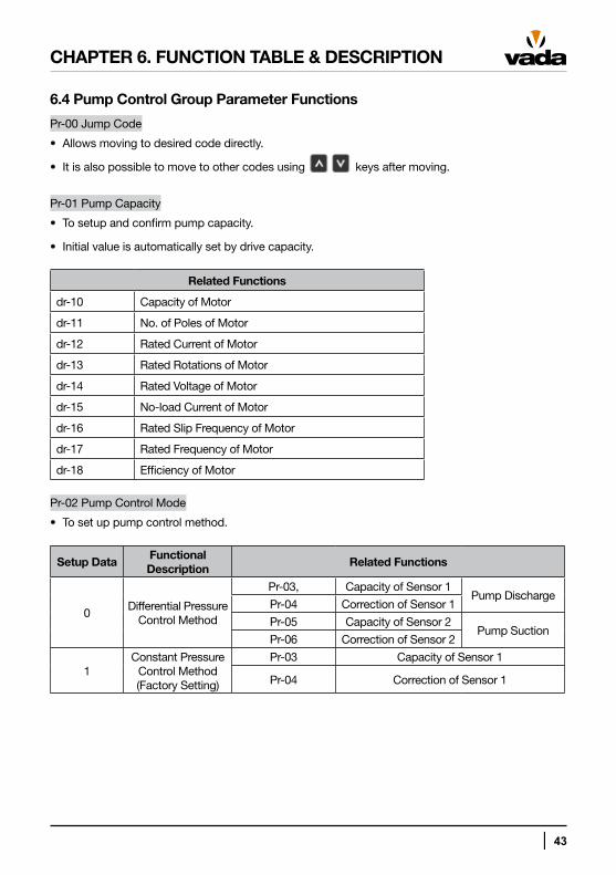
6.4 Pump Control Group Parameter Functions
Pr-00 Jump Code
• Allows moving to desired code directly.
• It is also possible to move to other codes using keys after moving.
Pr-01 Pump Capacity
• To setup and confirm pump capacity.
• Initial value is automatically set by drive capacity.
Related Functions
dr-10 Capacity of Motor
dr-11 No. of Poles of Motor
dr-12 Rated Current of Motor
dr-13 Rated Rotations of Motor
dr-14 Rated Voltage of Motor
dr-15 No-load Current of Motor
dr-16 Rated Slip Frequency of Motor
dr-17 Rated Frequency of Motor
dr-18 Efficiency of Motor
Pr-02 Pump Control Mode
• To set up pump control method.
Setup DataFunctional Description
Related Functions
0Differential Pressure
Control Method
Pr-03, Capacity of Sensor 1Pump Discharge
Pr-04 Correction of Sensor 1
Pr-05 Capacity of Sensor 2Pump Suction
Pr-06 Correction of Sensor 2
1Constant Pressure
Control Method (Factory Setting)
Pr-03 Capacity of Sensor 1
Pr-04 Correction of Sensor 1
44 │
CHAPTER 6. FUNCTION TABLE & DESCRIPTION
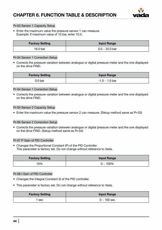
Pr-03 Sensor 1 Capacity Setup
• Enter the maximum value the pressure sensor 1 can measure. Example: If maximum value of 10 bar, enter 10.0.
Factory Setting Input Range
16.0 bar 0.0 ~ 25.0 bar
Pr-04 Sensor 1 Correction Setup
• Corrects the pressure variation between analogue or digital pressure meter and the one displayed on the drive FIND.
Factory Setting Input Range
0.0 bar -1.0 ~ 1.0 bar
Pr-04 Sensor 1 Correction Setup
• Corrects the pressure variation between analogue or digital pressure meter and the one displayed on the drive FIND.
Pr-05 Sensor 2 Capacity Setup
• Enter the maximum value the pressure sensor 2 can measure. (Setup method same as Pr-03)
Pr-06 Sensor 2 Correction Setup
• Corrects the pressure variation between analogue or digital pressure meter and the one displayed on the drive FIND. (Setup method same as Pr-04)
Pr-07 P Gain of PID Controller
• Changes the Proportional Constant (P) of the PID Controller This parameter is factory set. Do not change without reference to Vada.
Factory Setting Input Range
10% 0 ~ 100%
Pr-08 I Gain of PID Controller
• Changes the Integral Constant (I) of the PID controller.
• This parameter is factory set. Do not change without reference to Vada.
Factory Setting Input Range
1 sec 0 ~ 100 sec
│ 45
CHAPTER 6. FUNCTION TABLE & DESCRIPTION
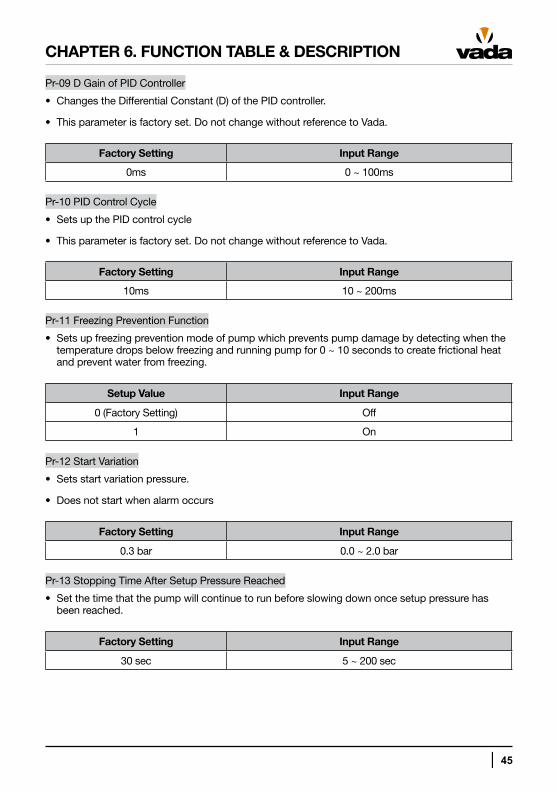
Pr-09 D Gain of PID Controller
• Changes the Differential Constant (D) of the PID controller.
• This parameter is factory set. Do not change without reference to Vada.
Factory Setting Input Range
0ms 0 ~ 100ms
Pr-10 PID Control Cycle
• Sets up the PID control cycle
• This parameter is factory set. Do not change without reference to Vada.
Factory Setting Input Range
10ms 10 ~ 200ms
Pr-11 Freezing Prevention Function
• Sets up freezing prevention mode of pump which prevents pump damage by detecting when the temperature drops below freezing and running pump for 0 ~ 10 seconds to create frictional heat and prevent water from freezing.
Setup Value Input Range
0 (Factory Setting) Off
1 On
Pr-12 Start Variation
• Sets start variation pressure.
• Does not start when alarm occurs
Factory Setting Input Range
0.3 bar 0.0 ~ 2.0 bar
Pr-13 Stopping Time After Setup Pressure Reached
• Set the time that the pump will continue to run before slowing down once setup pressure has been reached.
Factory Setting Input Range
30 sec 5 ~ 200 sec
46 │
CHAPTER 6. FUNCTION TABLE & DESCRIPTION
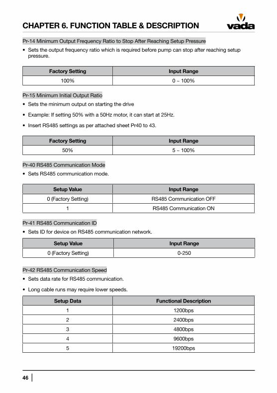
Pr-14 Minimum Output Frequency Ratio to Stop After Reaching Setup Pressure
• Sets the output frequency ratio which is required before pump can stop after reaching setup pressure.
Factory Setting Input Range
100% 0 ~ 100%
Pr-15 Minimum Initial Output Ratio
• Sets the minimum output on starting the drive
• Example: If setting 50% with a 50Hz motor, it can start at 25Hz.
• Insert RS485 settings as per attached sheet Pr40 to 43.
Factory Setting Input Range
50% 5 ~ 100%
Pr-40 RS485 Communication Mode
• Sets RS485 communication mode.
Setup Value Input Range
0 (Factory Setting) RS485 Communication OFF
1 RS485 Communication ON
Pr-41 RS485 Communication ID
• Sets ID for device on RS485 communication network.
Setup Value Input Range
0 (Factory Setting) 0-250
Pr-42 RS485 Communication Speed
• Sets data rate for RS485 communication.
• Long cable runs may require lower speeds.
Setup Data Functional Description
1 1200bps
2 2400bps
3 4800bps
4 9600bps
5 19200bps
│ 47
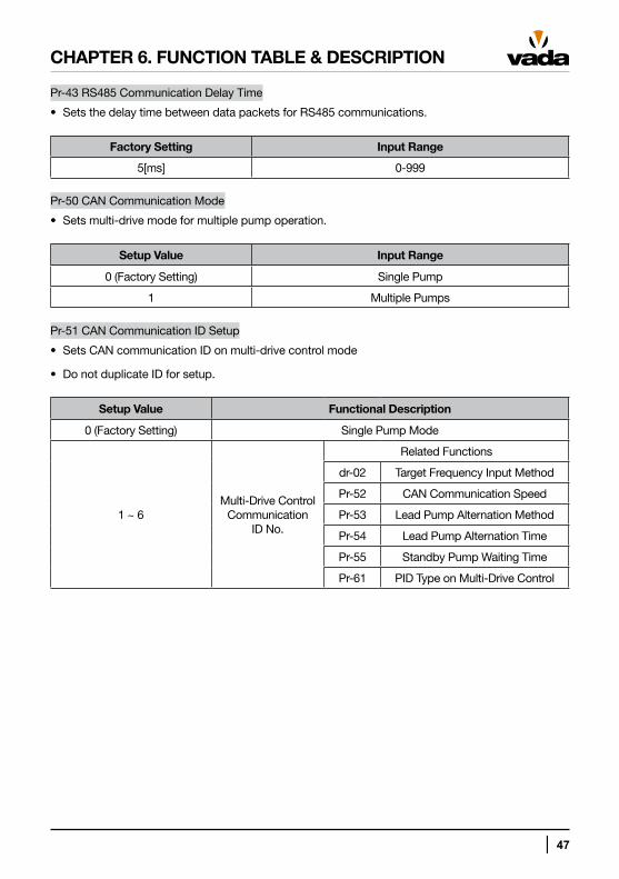
Pr-43 RS485 Communication Delay Time
• Sets the delay time between data packets for RS485 communications.
Factory Setting Input Range
5[ms] 0-999
Pr-50 CAN Communication Mode
• Sets multi-drive mode for multiple pump operation.
Setup Value Input Range
0 (Factory Setting) Single Pump
1 Multiple Pumps
Pr-51 CAN Communication ID Setup
• Sets CAN communication ID on multi-drive control mode
• Do not duplicate ID for setup.
Setup Value Functional Description
0 (Factory Setting) Single Pump Mode
1 ~ 6Multi-Drive Control
Communication ID No.
Related Functions
dr-02 Target Frequency Input Method
Pr-52 CAN Communication Speed
Pr-53 Lead Pump Alternation Method
Pr-54 Lead Pump Alternation Time
Pr-55 Standby Pump Waiting Time
Pr-61 PID Type on Multi-Drive Control
CHAPTER 6. FUNCTION TABLE & DESCRIPTION
48 │
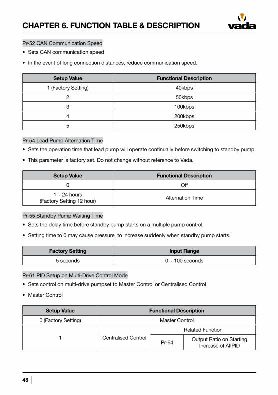
Pr-52 CAN Communication Speed
• Sets CAN communication speed
• In the event of long connection distances, reduce communication speed.
Setup Value Functional Description
1 (Factory Setting) 40kbps
2 50kbps
3 100kbps
4 200kbps
5 250kbps
Pr-54 Lead Pump Alternation Time
• Sets the operation time that lead pump will operate continually before switching to standby pump.
• This parameter is factory set. Do not change without reference to Vada.
Setup Value Functional Description
0 Off
1 ~ 24 hours (Factory Setting 12 hour)
Alternation Time
Pr-55 Standby Pump Waiting Time
• Sets the delay time before standby pump starts on a multiple pump control.
• Setting time to 0 may cause pressure to increase suddenly when standby pump starts.
Factory Setting Input Range
5 seconds 0 ~ 100 seconds
Pr-61 PID Setup on Multi-Drive Control Mode
• Sets control on multi-drive pumpset to Master Control or Centralised Control
• Master Control
Setup Value Functional Description
0 (Factory Setting) Master Control
1 Centralised Control
Related Function
Pr-64Output Ratio on Starting
Increase of AIIPID
CHAPTER 6. FUNCTION TABLE & DESCRIPTION
│ 49
CHAPTER 6. FUNCTION TABLE & DESCRIPTION
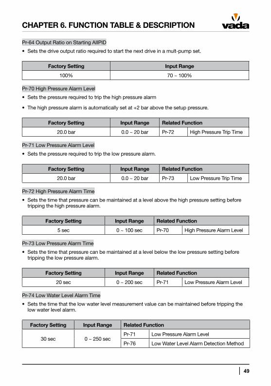
Pr-64 Output Ratio on Starting AIIPID
• Sets the drive output ratio required to start the next drive in a mult-pump set.
Factory Setting Input Range
100% 70 ~ 100%
Pr-70 High Pressure Alarm Level
• Sets the pressure required to trip the high pressure alarm
• The high pressure alarm is automatically set at +2 bar above the setup pressure.
Factory Setting Input Range Related Function
20.0 bar 0.0 ~ 20 bar Pr-72 High Pressure Trip Time
Pr-71 Low Pressure Alarm Level
• Sets the pressure required to trip the low pressure alarm.
Factory Setting Input Range Related Function
20.0 bar 0.0 ~ 20 bar Pr-73 Low Pressure Trip Time
Pr-72 High Pressure Alarm Time
• Sets the time that pressure can be maintained at a level above the high pressure setting before tripping the high pressure alarm.
Factory Setting Input Range Related Function
5 sec 0 ~ 100 sec Pr-70 High Pressure Alarm Level
Pr-73 Low Pressure Alarm Time
• Sets the time that pressure can be maintained at a level below the low pressure setting before tripping the low pressure alarm.
Factory Setting Input Range Related Function
20 sec 0 ~ 200 sec Pr-71 Low Pressure Alarm Level
Pr-74 Low Water Level Alarm Time
• Sets the time that the low water level measurement value can be maintained before tripping the low water level alarm.
Factory Setting Input Range Related Function
30 sec 0 ~ 250 secPr-71 Low Pressure Alarm Level
Pr-76 Low Water Level Alarm Detection Method
50 │
CHAPTER 6. FUNCTION TABLE & DESCRIPTION
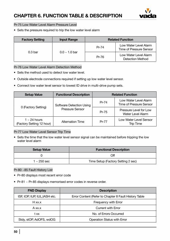
Pr-75 Low Water Level Alarm Pressure Level
• Sets the pressure required to trip the low water level alarm
Factory Setting Input Range Related Function
0.3 bar 0.0 ~ 1.0 bar
Pr-74Low Water Level Alarm
Time of Pressure Sensor
Pr-76Low Water Level Alarm
Detection Method
Pr-76 Low Water Level Alarm Detection Method
• Sets the method used to detect low water level.
• Outside electrode connections required if setting up low water level sensor.
• Connect low water level sensor to lowest ID drive in multi-drive pump sets.
Setup Value Functional Description Related Function
0 (Factory Setting)Software Detection Using
Pressure Sensor
Pr-74Low Water Level Alarm
Time of Pressure Sensor
Pr-75Pressure Level for Low
Water Level Alarm
1 ~ 24 hours (Factory Setting 12 hour)
Alternation Time Pr-77Low Water Level Sensor
Trip Time
Pr-77 Low Water Level Sensor Trip Time
• Sets the time that the low water level sensor signal can be maintained before tripping the low water level alarm
Setup Value Functional Description
0 Off
1 ~ 250 sec Time Setup (Factory Setting 2 sec)
Pr-80 ~85 Fault History List
• Pr-80 displays most recent error code
• Pr-81 ~ Pr-85 displays memorised error codes in reverse order.
FND Display Description
tSF, tOP, tUP, tUL,tASH etc. Error Content (Refer to Chapter 8 Fault History Table
H xx.x Frequency with Error
A xx.x Current with Error
t xx No. of Errors Occurred
Stdy, stOP, AdOFS, wdOG Operation Status with Error
│ 51
CHAPTER 6. FUNCTION TABLE & DESCRIPTION
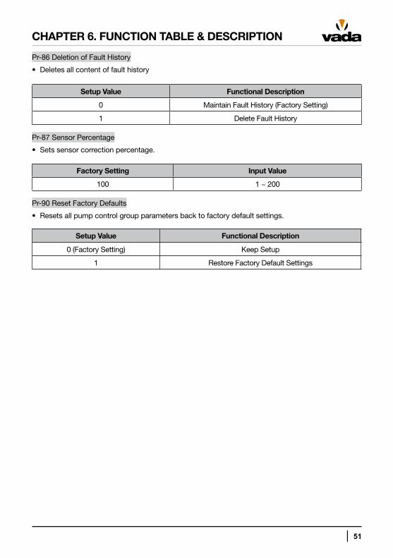
Pr-86 Deletion of Fault History
• Deletes all content of fault history
Setup Value Functional Description
0 Maintain Fault History (Factory Setting)
1 Delete Fault History
Pr-87 Sensor Percentage
• Sets sensor correction percentage.
Factory Setting Input Value
100 1 ~ 200
Pr-90 Reset Factory Defaults
• Resets all pump control group parameters back to factory default settings.
Setup Value Functional Description
0 (Factory Setting) Keep Setup
1 Restore Factory Default Settings
52 │
CHAPTER 6. FUNCTION TABLE & DESCRIPTION
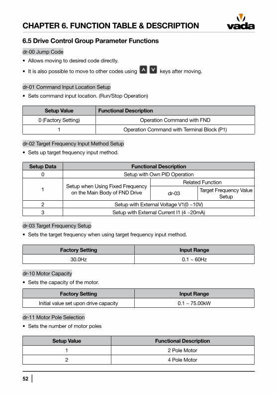
6.5 Drive Control Group Parameter Functions
dr-00 Jump Code
• Allows moving to desired code directly.
• It is also possible to move to other codes using keys after moving.
dr-01 Command Input Location Setup
• Sets command input location. (Run/Stop Operation)
Setup Value Functional Description
0 (Factory Setting) Operation Command with FND
1 Operation Command with Terminal Block (P1)
dr-02 Target Frequency Input Method Setup
• Sets up target frequency input method.
Setup Data Functional Description
0 Setup with Own PID Operation
1Setup when Using Fixed Frequency
on the Main Body of FND Drive
Related Function
dr-03Target Frequency Value
Setup
2 Setup with External Voltage V1(0 ~10V)
3 Setup with External Current I1 (4 ~20mA)
dr-03 Target Frequency Setup
• Sets the target frequency when using target frequency input method.
Factory Setting Input Range
30.0Hz 0.1 ~ 60Hz
dr-10 Motor Capacity
• Sets the capacity of the motor.
Factory Setting Input Range
Initial value set upon drive capacity 0.1 ~ 75.00kW
dr-11 Motor Pole Selection
• Sets the number of motor poles
Setup Value Functional Description
1 2 Pole Motor
2 4 Pole Motor
│ 53
CHAPTER 6. FUNCTION TABLE & DESCRIPTION
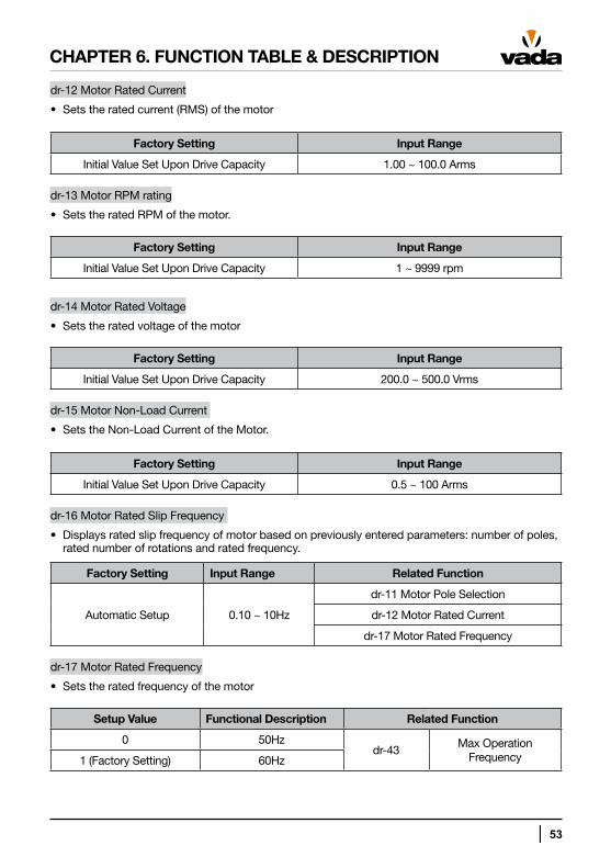
dr-12 Motor Rated Current
• Sets the rated current (RMS) of the motor
Factory Setting Input Range
Initial Value Set Upon Drive Capacity 1.00 ~ 100.0 Arms
dr-13 Motor RPM rating
• Sets the rated RPM of the motor.
Factory Setting Input Range
Initial Value Set Upon Drive Capacity 1 ~ 9999 rpm
dr-14 Motor Rated Voltage
• Sets the rated voltage of the motor
Factory Setting Input Range
Initial Value Set Upon Drive Capacity 200.0 ~ 500.0 Vrms
dr-15 Motor Non-Load Current
• Sets the Non-Load Current of the Motor.
Factory Setting Input Range
Initial Value Set Upon Drive Capacity 0.5 ~ 100 Arms
dr-16 Motor Rated Slip Frequency
• Displays rated slip frequency of motor based on previously entered parameters: number of poles, rated number of rotations and rated frequency.
Factory Setting Input Range Related Function
Automatic Setup 0.10 ~ 10Hz
dr-11 Motor Pole Selection
dr-12 Motor Rated Current
dr-17 Motor Rated Frequency
dr-17 Motor Rated Frequency
• Sets the rated frequency of the motor
Setup Value Functional Description Related Function
0 50Hzdr-43
Max Operation Frequency1 (Factory Setting) 60Hz
54 │
CHAPTER 6. FUNCTION TABLE & DESCRIPTION
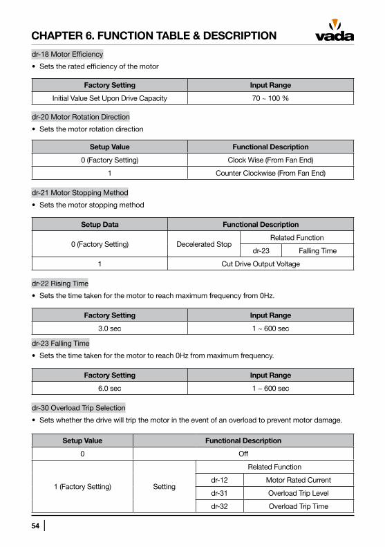
dr-18 Motor Efficiency
• Sets the rated efficiency of the motor
Factory Setting Input Range
Initial Value Set Upon Drive Capacity 70 ~ 100 %
dr-20 Motor Rotation Direction
• Sets the motor rotation direction
Setup Value Functional Description
0 (Factory Setting) Clock Wise (From Fan End)
1 Counter Clockwise (From Fan End)
dr-21 Motor Stopping Method
• Sets the motor stopping method
Setup Data Functional Description
0 (Factory Setting) Decelerated StopRelated Function
dr-23 Falling Time
1 Cut Drive Output Voltage
dr-22 Rising Time
• Sets the time taken for the motor to reach maximum frequency from 0Hz.
Factory Setting Input Range
3.0 sec 1 ~ 600 sec
dr-23 Falling Time
• Sets the time taken for the motor to reach 0Hz from maximum frequency.
Factory Setting Input Range
6.0 sec 1 ~ 600 sec
dr-30 Overload Trip Selection
• Sets whether the drive will trip the motor in the event of an overload to prevent motor damage.
Setup Value Functional Description
0 Off
1 (Factory Setting) Setting
Related Function
dr-12 Motor Rated Current
dr-31 Overload Trip Level
dr-32 Overload Trip Time
│ 55
CHAPTER 6. FUNCTION TABLE & DESCRIPTION
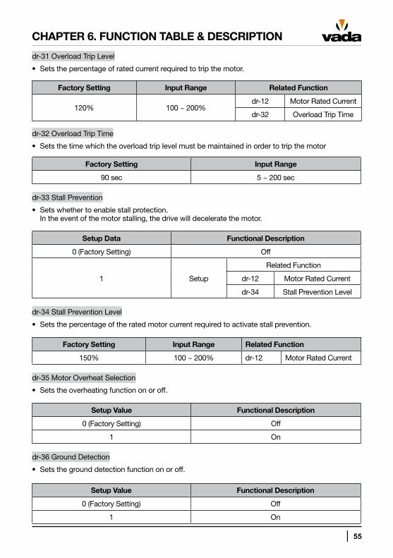
dr-31 Overload Trip Level
• Sets the percentage of rated current required to trip the motor.
Factory Setting Input Range Related Function
120% 100 ~ 200%dr-12 Motor Rated Current
dr-32 Overload Trip Time
dr-32 Overload Trip Time
• Sets the time which the overload trip level must be maintained in order to trip the motor
Factory Setting Input Range
90 sec 5 ~ 200 sec
dr-33 Stall Prevention
• Sets whether to enable stall protection. In the event of the motor stalling, the drive will decelerate the motor.
Setup Data Functional Description
0 (Factory Setting) Off
1 Setup
Related Function
dr-12 Motor Rated Current
dr-34 Stall Prevention Level
dr-34 Stall Prevention Level
• Sets the percentage of the rated motor current required to activate stall prevention.
Factory Setting Input Range Related Function
150% 100 ~ 200% dr-12 Motor Rated Current
dr-35 Motor Overheat Selection
• Sets the overheating function on or off.
Setup Value Functional Description
0 (Factory Setting) Off
1 On
dr-36 Ground Detection
• Sets the ground detection function on or off.
Setup Value Functional Description
0 (Factory Setting) Off
1 On
56 │
CHAPTER 6. FUNCTION TABLE & DESCRIPTION
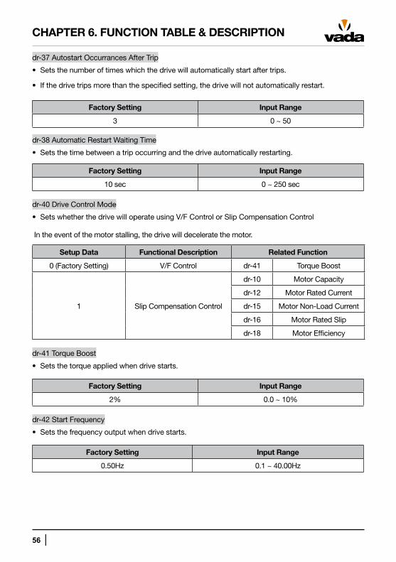
dr-37 Autostart Occurrances After Trip
• Sets the number of times which the drive will automatically start after trips.
• If the drive trips more than the specified setting, the drive will not automatically restart.
Factory Setting Input Range
3 0 ~ 50
dr-38 Automatic Restart Waiting Time
• Sets the time between a trip occurring and the drive automatically restarting.
Factory Setting Input Range
10 sec 0 ~ 250 sec
dr-40 Drive Control Mode
• Sets whether the drive will operate using V/F Control or Slip Compensation Control
●In the event of the motor stalling, the drive will decelerate the motor.
Setup Data Functional Description Related Function
0 (Factory Setting) V/F Control dr-41 Torque Boost
1 Slip Compensation Control
dr-10 Motor Capacity
dr-12 Motor Rated Current
dr-15 Motor Non-Load Current
dr-16 Motor Rated Slip
dr-18 Motor Efficiency
dr-41 Torque Boost
• Sets the torque applied when drive starts.
Factory Setting Input Range
2% 0.0 ~ 10%
dr-42 Start Frequency
• Sets the frequency output when drive starts.
Factory Setting Input Range
0.50Hz 0.1 ~ 40.00Hz
│ 57
CHAPTER 6. FUNCTION TABLE & DESCRIPTION
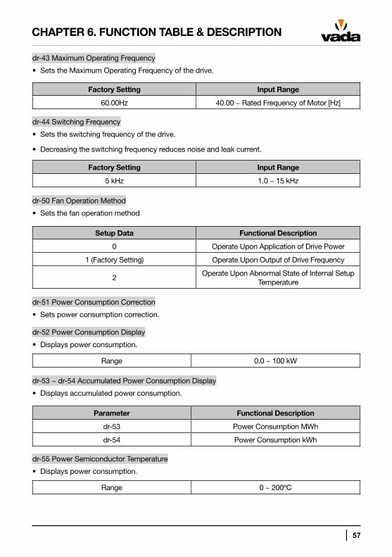
dr-43 Maximum Operating Frequency
• Sets the Maximum Operating Frequency of the drive.
Factory Setting Input Range
60.00Hz 40.00 ~ Rated Frequency of Motor [Hz]
dr-44 Switching Frequency
• Sets the switching frequency of the drive.
• Decreasing the switching frequency reduces noise and leak current.
Factory Setting Input Range
5 kHz 1.0 ~ 15 kHz
dr-50 Fan Operation Method
• Sets the fan operation method
Setup Data Functional Description
0 Operate Upon Application of Drive Power
1 (Factory Setting) Operate Upon Output of Drive Frequency
2Operate Upon Abnormal State of Internal Setup
Temperature
dr-51 Power Consumption Correction
• Sets power consumption correction.
dr-52 Power Consumption Display
• Displays power consumption.
Range 0.0 ~ 100 kW
dr-53 ~ dr-54 Accumulated Power Consumption Display
• Displays accumulated power consumption.
Parameter Functional Description
dr-53 Power Consumption MWh
dr-54 Power Consumption kWh
dr-55 Power Semiconductor Temperature
• Displays power consumption.
Range 0 ~ 200ºC
58 │
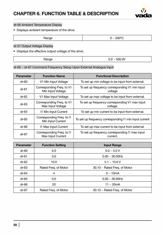
dr-56 Ambient Temperature Display
• Displays ambient temperature of the drive.
Range 0 ~ 200ºC
dr-57 Output Voltage Display
• Displays the effective output voltage of the drive.
Range 0.0 ~ 500.0V
dr-60 ~ dr-67 Command Frequency Setup Upon External Analogue Input
Parameter Function Name Functional Description
dr-60 V1 Min Input Voltage To set up min voltage to be input from external.
dr-61Corresponding Freq. to V1
Min Input VoltageTo set up frequency corresponding V1 min input
voltage
dr-62 V1 Max Input Voltage To set up max voltage to be input from external.
dr-63Corresponding Freq. to V1
Max Input VoltageTo set up frequency corresponding V1 max input
voltage.
dr-64 I1 Min Input Current To set up min current to be input from external.
dr-65Corresponding Freq. to I1
Min Input CurrentTo set up frequency corresponding I1 min input current
dr-66 I1 Max Input Current To set up max current to be input from external.
dr-67Corresponding Freq. to I1
Max Input CurrentTo set up frequency corresponding I1 max input
current.
Parameter Function Setting Input Range
dr-60 0.0 0.0 ~ 5.0 V
dr-61 0.0 0.00 ~ 30.00Hz
dr-62 10.0 5.1 ~ 10.0 V
dr-63 Rated Freq. of Motor 30.10 ~ Rated Freq. of Motor
dr-64 4 0 ~ 10mA
dr-65 0.0 0.00 ~ 30.00Hz
dr-66 20 11 ~ 20mA
dr-67 Rated Freq. of Motor 30.10 ~ Rated Freq. of Motor
CHAPTER 6. FUNCTION TABLE & DESCRIPTION
│ 59
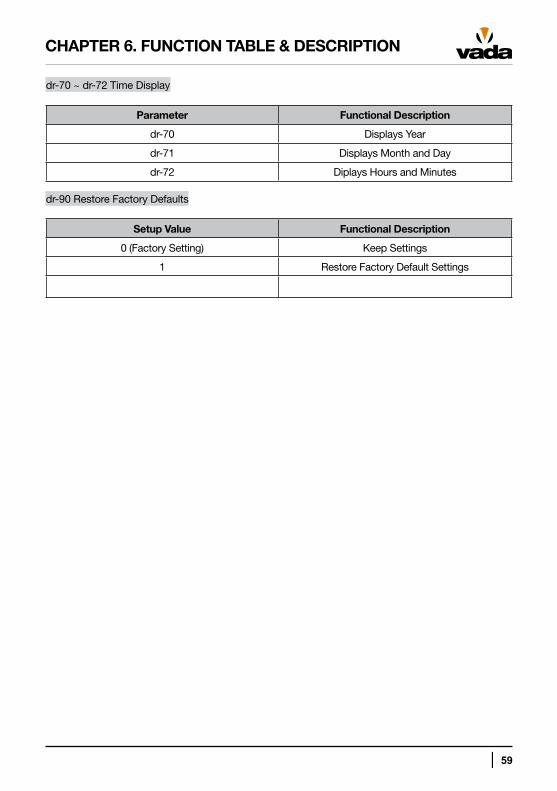
dr-70 ~ dr-72 Time Display
Parameter Functional Description
dr-70 Displays Year
dr-71 Displays Month and Day
dr-72 Diplays Hours and Minutes
dr-90 Restore Factory Defaults
Setup Value Functional Description
0 (Factory Setting) Keep Settings
1 Restore Factory Default Settings
CHAPTER 6. FUNCTION TABLE & DESCRIPTION
60 │
CHAPTER 7. TROUBLESHOOTING
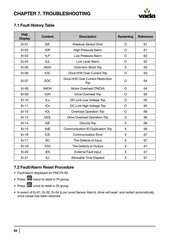
7.1 Fault History Table
FND Display
Content Description Restarting Reference
Er-01 tSF Pressure Sensor Error O 61
Er-02 tOP High Pressure Alarm O 61
Er-03 tLP Low Pressure Alarm O 62
Er-04 tUL Low Level Alarm O 62
Er-05 tASH Drive Arm Short Trip X 63
Er-06 tOC Drive H/W Over Current Trip O 63
Er-07 SOCDrive H/W Over Current Restriction
TripO 64
Er-08 tMOH Motor Overheat (TMOH) O 64
Er-09 tOH Drive Overheat Trip O 65
Er-10 tLv DC-Link Low Voltage Trip O 65
Er-11 tOv DC-Link High Voltage Trip O 65
Er-12 tOL Overload Operation Trip O 66
Er-13 tdOL Drive Overload Operation Trip O 66
Er-14 tGF Ground Trip X 66
Er-15 tIdE Communication ID Duplication Trip X 66
Er-16 tCE Communication Error X 67
Er-17 tIO The Defects of Input X 67
Er-18 tOO The Defects of Output X 67
Er-20 tES External Fault Input X 67
Er-21 tLt Allowable Time Elapsed X 67
7.2 Fault/Alarm Reset Procedure• Fault/alarm displayed on FND Pr-80.
• Press twice to reset in Pr-group
• Press once to reset in St-group
• In event of Er-01, Er-02, Er-04 (Low Level Sensor Alarm), drive will reset and restart automatically once cause has been resolved.
│ 61
CHAPTER 7. TROUBLESHOOTING
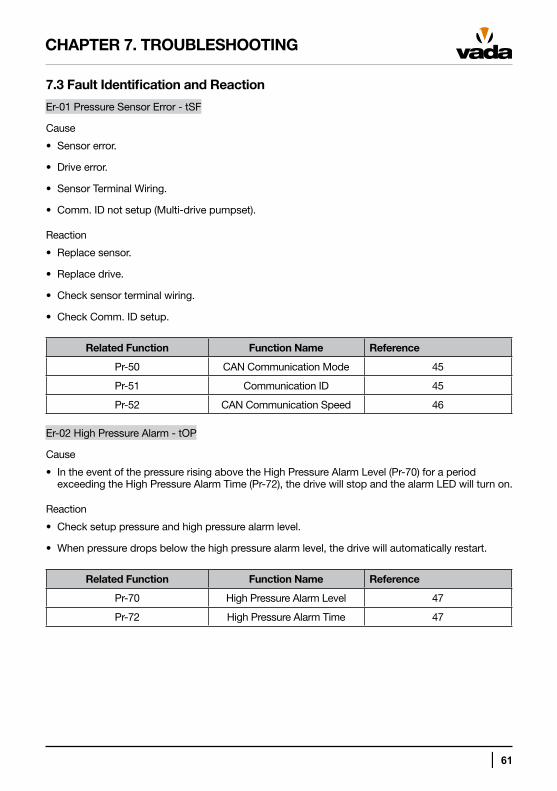
7.3 Fault Identification and Reaction
Er-01 Pressure Sensor Error - tSF
Cause
• Sensor error.
• Drive error.
• Sensor Terminal Wiring.
• Comm. ID not setup (Multi-drive pumpset).
Reaction
• Replace sensor.
• Replace drive.
• Check sensor terminal wiring.
• Check Comm. ID setup.
Related Function Function Name Reference
Pr-50 CAN Communication Mode 45
Pr-51 Communication ID 45
Pr-52 CAN Communication Speed 46
Er-02 High Pressure Alarm - tOP
Cause
• In the event of the pressure rising above the High Pressure Alarm Level (Pr-70) for a period exceeding the High Pressure Alarm Time (Pr-72), the drive will stop and the alarm LED will turn on.
Reaction
• Check setup pressure and high pressure alarm level.
• When pressure drops below the high pressure alarm level, the drive will automatically restart.
Related Function Function Name Reference
Pr-70 High Pressure Alarm Level 47
Pr-72 High Pressure Alarm Time 47
62 │
CHAPTER 7. TROUBLESHOOTING
Er-03 Low Pressure Alarm - tLP
Cause
• Pressure dropping below the Low Pressure Alarm Level (Pr-71) for a period exceeding the Low Pressure Alarm Time (Pr-73).
• The drive will automatically restart after the Automatic Restart Time (dr-38). If the drive trips the number of times specified by Autostart Occurrences After Trip (dr-37) it will not restart.
Reaction
• Check water tank (reservoir) is full.
• Check pump for air.
• Check pump for water by opening air cock.
• Press to release error and to start the pump.
Related Function Function Name Reference
Pr-71 Low Pressure Alarm Level 47
Pr-73 Low Pressure Alarm Time 47
dr-37 No. of Automatic Restart after Trip 54
dr-38 Waiting Time for Automatic Restart after Trip 54
Er-04 Low Water Level Alarm - tUL
Cause
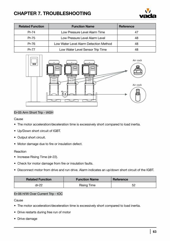
• When using a low water level sensor, the alarm will be generated when the electrode detects no water on the suction side of the pump.
• When using a low water level sensor, the drive will automatically restart when water is detected in the suction side of the pump.
• When using software low water level detection, the alarm will be generated when the pressure is maintained below the Low Pressure Alarm Level (Pr-75) for a period of time exceeding the Low Pressure Alarm Time (Pr-74).
Reaction
• Check water tank (reservoir) is full.
●Check pump for water by opening air cock.
• Press to release error and to start the pump.
│ 63
CHAPTER 7. TROUBLESHOOTING
Related Function Function Name Reference
Pr-74 Low Pressure Level Alarm Time 47
Pr-75 Low Pressure Level Alarm Level 48
Pr-76 Low Water Level Alarm Detection Method 48
Pr-77 Low Water Level Sensor Trip Time 48
Er-05 Arm Short Trip - tASH
Cause
• The motor acceleration/deceleration time is excessively short compared to load inertia.
• Up/Down short circuit of IGBT.
• Output short circuit.
• Motor damage due to fire or insulation defect.
Reaction
• Increase Rising Time (dr-22).
• Check for motor damage from fire or insulation faults.
• Disconnect motor from drive and run drive. Alarm indicates an up/down short circuit of the IGBT.
Related Function Function Name Reference
dr-22 Rising Time 52
Er-06 H/W Over Current Trip - tOC
Cause
• The motor acceleration/deceleration time is excessively short compared to load inertia.
• Drive restarts during free run of motor
• Drive damage
64 │
Reaction
• Adjust the Rising Time (dr-22) or Falling Time (dr-23).
• Check the drive capacity matches the motor capacity.
• Start pump after the motor has stopped.
• Check load, motor and output wiring.
Related Function Function Name Reference
dr-21 Motor Stopping Method 52
dr-22 Rising Time 52
dr-23 Falling Time 52
Er-07 H/W Over Current Restriction Trip - SOC
Cause
• The motor acceleration/deceleration time is excessively short compared to load inertia.
• Drive restarts during free run of motor.
• Generation of over current due to sudden overload.
Reaction
• Adjust the Rising Time (dr-22) or Falling Time (dr-23).
• Check the drive capacity matches the motor capacity.
• Start pump after the motor has stopped.
• Adjust Torque Boost (dr-41).
Related Function Function Name Reference
dr-10 Motor Capacity 50
dr-21 Motor Stopping Method 52
dr-22 Rising Time 52
dr-23 Falling Time 52
dr-41 Torque Boost Amount 54
Er-08 Motor Overheat - tMOH
Cause
• Motor overheating.
• Load in excess of drive rating.
• Incorrect selection of drive capacity.
• Excessive low speed operation.
CHAPTER 7. TROUBLESHOOTING
│ 65
Reaction
• Check load capacity is suitable for drive rating.
• Reduce load or number of operations.
Related Function Function Name Reference
dr-10 Motor Capacity 50
dr-35 Motor Overheat Selection 53
Er-09 Overheat Trip - tOH
Cause
• Cooling fan interruption or fault.
• Excessively high ambient temperature.
Reaction
• Check cooling fan for faults or obstructions.
• Check that the ambient temperature does not exceed 40ºC.
Er-10 Low Voltage Trip - tLv
Cause
• Power supply voltage too low.
• Load in excess of the power capacity.
Reaction
• Check drive input voltage.
• Check power capacity.
Er-11 High Voltage Trip - tOv
Cause
• Falling time is too short compared to load inertia.
• Excessive drive input voltage.
Reaction
• Increase Falling Time (dr-23).
• Check driver power supply voltage.
Related Function Function Name Reference
dr-23 Falling Time 52
CHAPTER 7. TROUBLESHOOTING
66 │
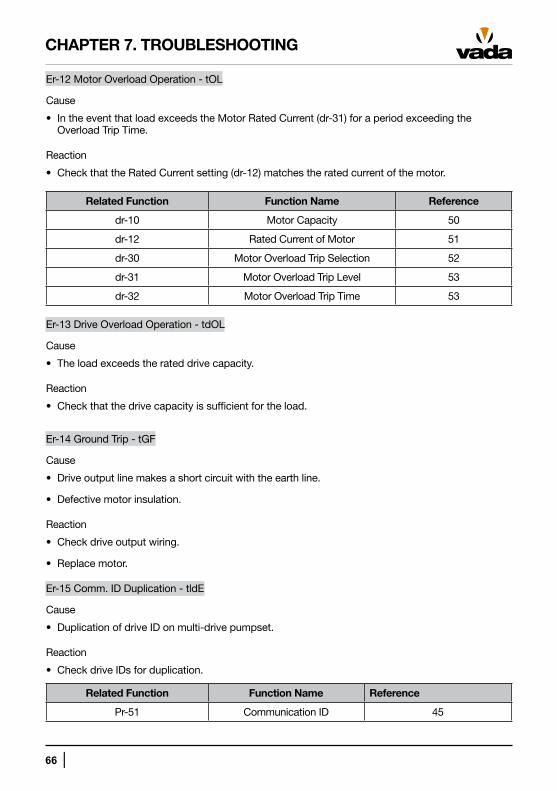
Er-12 Motor Overload Operation - tOL
Cause
• In the event that load exceeds the Motor Rated Current (dr-31) for a period exceeding the Overload Trip Time.
Reaction
• Check that the Rated Current setting (dr-12) matches the rated current of the motor.
Related Function Function Name Reference
dr-10 Motor Capacity 50
dr-12 Rated Current of Motor 51
dr-30 Motor Overload Trip Selection 52
dr-31 Motor Overload Trip Level 53
dr-32 Motor Overload Trip Time 53
Er-13 Drive Overload Operation - tdOL
Cause
• The load exceeds the rated drive capacity.
Reaction
• Check that the drive capacity is sufficient for the load.
Er-14 Ground Trip - tGF
Cause
• Drive output line makes a short circuit with the earth line.
• Defective motor insulation.
Reaction
• Check drive output wiring.
• Replace motor.
Er-15 Comm. ID Duplication - tldE
Cause
• Duplication of drive ID on multi-drive pumpset.
Reaction
• Check drive IDs for duplication.
Related Function Function Name Reference
Pr-51 Communication ID 45
CHAPTER 7. TROUBLESHOOTING
│ 67
CHAPTER 7. TROUBLESHOOTING
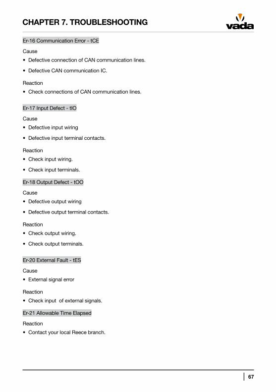
Er-16 Communication Error - tCE
Cause
• Defective connection of CAN communication lines.
• Defective CAN communication IC.
Reaction
• Check connections of CAN communication lines.
Er-17 Input Defect - tIO
Cause
• Defective input wiring
• Defective input terminal contacts.
Reaction
• Check input wiring.
• Check input terminals.
Er-18 Output Defect - tOO
Cause
• Defective output wiring
• Defective output terminal contacts.
Reaction
• Check output wiring.
• Check output terminals.
Er-20 External Fault - tES
Cause
• External signal error
Reaction
• Check input of external signals.
Er-21 Allowable Time Elapsed
Reaction
• Contact your local Reece branch.
WARRANTY
You have purchased a quality product from Reece Australia. This product is covered by a 24 month warranty. This warranty covers faults in the product construction, material and assembly. Faulty products will be repaired or exchanged free of charge. Faulty items become our property.
This warranty does not include faults caused by:
• Unsuitable or improper use
• Incorrect installation
• Normal wear and tear
• Inadequate or complete lack of maintenance
• Chemical, electrochemical or electrical influences
To the maximum extent permitted by law, Reece excludes all warranties other than those set out above. In the event of a warranty claim, we will replace or repair defective products, or pay for the cost of having defective products repaired or replaced, but will not be liable for any injury to any person, damage to any property, any indirect or consequential loss, or in any other respect.
Disclaimer:
Products in this specification manual must by regulation be installed by licensed and registered trade people. The manufacturer/distributor reserves the right to vary specifications or delete models from their range without prior notification. Dimensions and set-outs listed are correct at time of publication however the manufacturer/distributor takes no responsibility for printing errors.
October 2013
L100
233
A10
13