Embed Size (px)
Citation preview
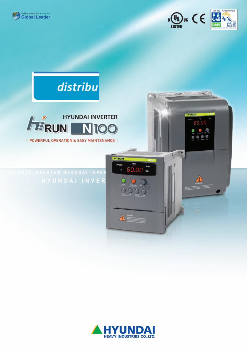
We build a better future!
P O W E R F U L O P E R A T I O N & E A S Y M A I N T E N A N C E
C O N T E N T S
Features 04
Operation 05
General Specifications 07
Function List 09
Protective Functions 15
N100 -
Inverter
Hyundai inverters feature sensorless vector & intelligent controls
which allow more efficient use of the inherent power of a motor
and an auto-tuning function capable of easily accomplishing
powerful operation.
Model number information
Series name
Applicable motor rating (0.4kW to7.5kW)
Input power supply specification (L: three-phase 200-V class)(H: three-phase 400-V class) (S: single-phase 200-V class)
Configuration type (operator panel equipped)
004 L F
Terminal Functions 16
Standard Connection Diagram 17
Application Wiring Apparatus & Options 18
Proper Operation 26
Features
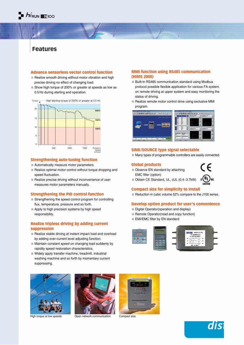
Advance sensorless vector control functionRealize smooth driving without motor vibration and high
precise driving no effect of changing load.
Show high torque of 200% or greater at speeds as low as
0.5 Hz during starting and operation.
MMI function using RS485 communication(HIMS 2000)Built-in RS485 communication standard using Modbus
protocol possible flexible application for various FA system,
on remote driving at upper system and easy monitoring the
status of driving.
Realize remote motor control drive using exclusive MMI
program.
SINK/SOURCE type signal selectableMany types of programmable controllers are easily connected.
Global productsObserve EN standard by attaching
EMC filter (option)
Obtain CE Standard, UL, cUL (0.4~3.7kW)
Compact size for simplicity to installReduction in cubic volume 52% compare to the J100 series.
Develop option product for user ’s convenienceDigital Operator(operation and display)
Remote Operator(read and copy function)
EMI/EMC filter by EN standard
Strengthening auto-tuning functionAutomatically measure motor parameters.
Realize optimal motor control without torque dropping and
speed fluctuation.
Realize precise driving without inconvenience of user
measures motor parameters manually.
Strengthening the PID control functionStrengthening the speed control program for controlling
flux, temperature, pressure and so forth.
Apply to high precision systems by high speed
responsibility.
Realize tripless driving by adding currentsuppressionRealize stable driving at instant impact load and overload
by adding over-current level adjusting function.
Maintain constant speed on changing load suddenly by
rapidity speed restoration characteristics.
Widely apply transfer machine, treadmill, industrial
washing machine and so forth by momentary current
suppressing.
High torque at low speeds Open network communication Compact size
Operation
Features / Operation 04 05
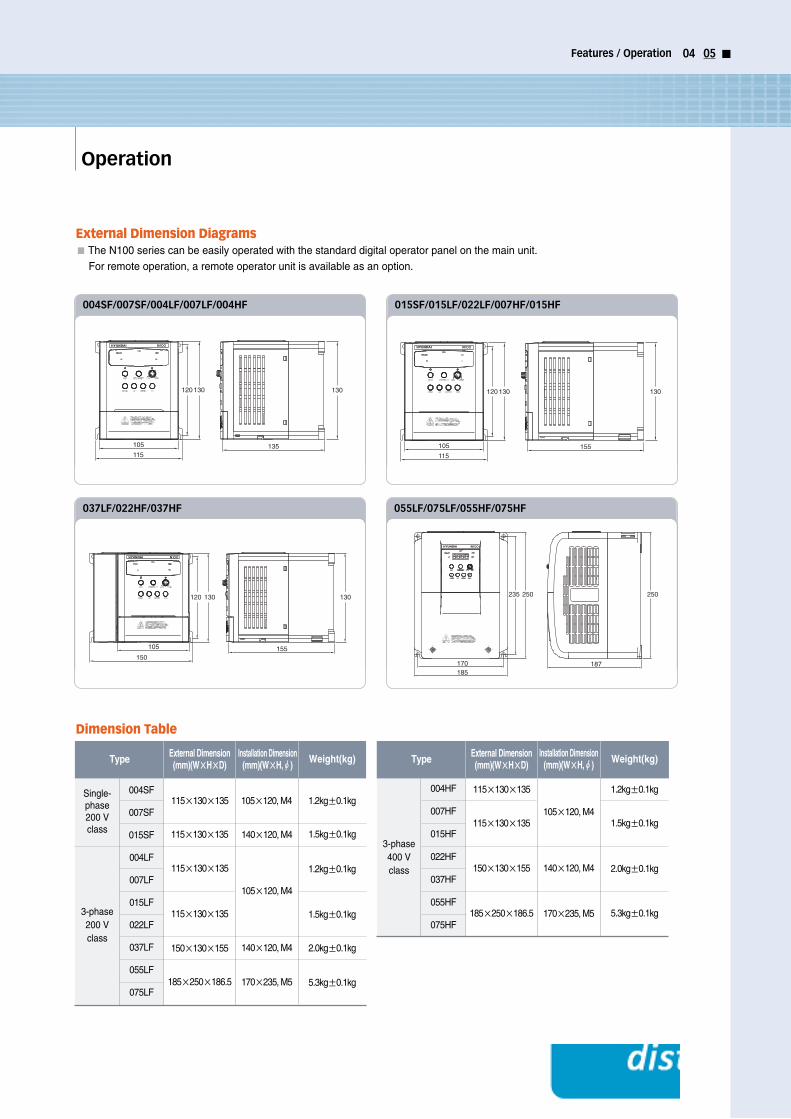
Dimension Table
115
105
120 130
135
130
004SF/007SF/004LF/007LF/004HF
115
105
120 130
155
130
015SF/015LF/022LF/007HF/015HF
105
120 130
155
130
150
037LF/022HF/037HF
185170
235 250 250
187
055LF/075LF/055HF/075HF
Type Weight(kg)External Dimension(mm)(W××H××D)
Installation Dimension(mm)(W××H,ØØ)
Single-phase200 Vclass
004SF
007SF
015SF
004LF
007LF
015LF
022LF
037LF
055LF
075LF
Type Weight(kg)External Dimension(mm)(W××H××D)
Installation Dimension(mm)(W××H,ØØ)
3-phase400 Vclass
115×130×135
105×120, M4
1.2kg±0.1kg
1.5kg±0.1kg
140×120, M4
170×235, M5
2.0kg±0.1kg
5.3kg±0.1kg
115×130×135
150×130×155
185×250×186.5
004HF
007HF
015HF
022HF
037HF
055HF
075HF3-phase200 Vclass
115×130×135
115×130×135
105×120, M4
1.2kg±0.1kg
1.2kg±0.1kg105×120, M4
1.5kg±0.1kg
140×120, M4
170×235, M5
140×120, M4
2.0kg±0.1kg
5.3kg±0.1kg
1.5kg±0.1kg
115×130×135
150×130×155
185×250×186.5
115×130×135
External Dimension DiagramsThe N100 series can be easily operated with the standard digital operator panel on the main unit.
For remote operation, a remote operator unit is available as an option.
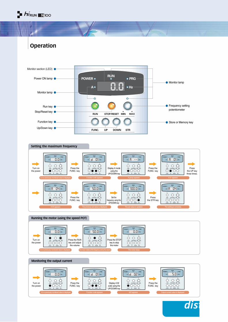
Operation
Monitor section (LED)
Monitor lamp
Frequency settingpotentiometer
Store or Memory key
Power ON lamp
Monitor lamp
Run key
Stop/Reset key
Function key
Up/Down key
Setting the maximum frequency
Running the motor (using the speed POT)
Monitoring the output current
0.0 or previously monitored value is displayed Function code appears
A 04 appears
0.0 or previously monitored value is displayed. The motor rotates at the frequency set by the volume
0.0 or previously monitored value is displayed Function code appears d02 appears Output current value is displayed
The motor stops
The previous set value is displayed. The set value is updated. The setting is complete.
A group appears A 01 appears
Turn on the power
Press theFUNC. key
Display A modeusing the
UP/DOWN key
Set the frequency using the
UP/DOWN key
Press theFUNC. key
Press the STR key
Press theFUNC. key
Press the UP keythree times.
Turn on the power
Press the RUNkey and adjust
the volume
Press the STOP key to stopthe motor
Turn on the power
Press the
FUNC. keyDisplay d 02
code using theUP/DOWN key
Press theFUNC. key
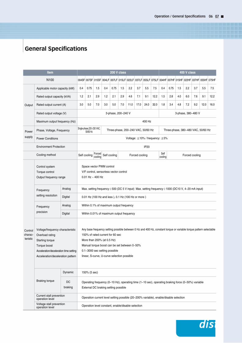
General Specifications
Operation / General Specifications 06 07
Item 400 V class200 V class
N100
Output
Power
supply
Controlcharac-teristic
Analog
Digital
Analog
Digital
Dynamic
DC
braking
Applicable motor capacity (kW)
Rated output capacity (kVA)
Rated output current (A)
Rated output voltage (V)
Maximum output frequency (Hz)
3-phase, 200~240 V
Space vector PWM control
V/F control, sensorless vector control
0.01 Hz ~ 400 Hz
Within 0.1% of maximum output frequency
Within 0.01% of maximum output frequency
Max. setting frequency÷500 (DC 5 V input) Max. setting frequency÷1000 (DC10 V, 4~20 mA input)
0.01 Hz (100 Hz and less ), 0.1 Hz (100 Hz or more )
Any base frequency setting possible between 0 Hz and 400 Hz, constant torque or variable torque pattern selectable
150% of rated current for 60 sec
More than 200% (at 0.5 Hz)
Manual torque boost can be set between 0~50%
0.1~3000 sec setting possible
linear, S-curve, U-curve selection possible
150% (5 sec)
Operating frequency (0~10 Hz), operating time (1~10 sec), operating braking force (0~50%) variable
External DC braking setting possible
Operation current level setting possible (20~200% variable), enable/disable selection
Operation level constant, enable/disable selection
Single-phase,220~230 VAC,50/60 Hz Three-phase, 200~240 VAC, 50/60 Hz Three-phase, 380~480 VAC, 50/60 Hz
400 Hz
Voltage: ±10% / frequency: ±5%
IP20
Self cooling Forcedcooling Self cooling Forced cooling Self
cooling Forced cooling
3-phase, 380~480 V
Phase, Voltage, Frequency
Power Conditions
Environment Protection
Cooling method
Control system
Torque control
Output frequency range
Voltage/frequency characteristic
Overload rating
Starting torque
Torque boost
Acceleration/deceleration time setting
Acceleration/deceleration pattern
Braking torque
Current stall prevention operation level
Voltage stall prevention operation level
Frequency
setting resolution
Frequency
precision
004SF
0.4
1.2
3.0
007SF
0.75
2.1
5.0
015SF
1.5
2.9
7.0
004LF
0.4
1.2
3.0
007LF
0.75
2.1
5.0
015LF
1.5
2.9
7.0
022LF
2.2
4.6
11.0
037LF
3.7
7.1
17.0
055LF
5.5
9.1
24.0
075LF
7.5
12.2
32.0
004HF
0.4
1.5
1.8
007HF
0.75
2.8
3.4
015HF
1.5
4.0
4.8
022HF
2.2
6.0
7.2
037HF
3.7
7.6
9.2
055HF
5.5
9.1
12.0
075HF
7.5
12.2
16.0
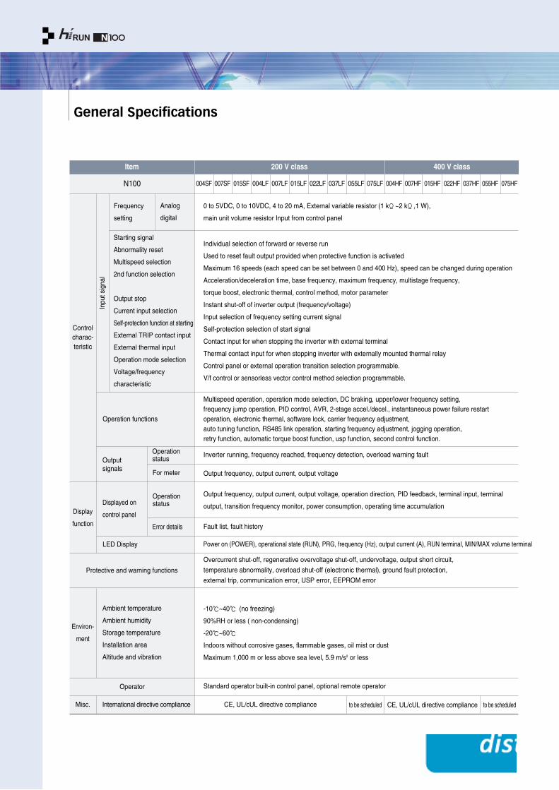
General Specifications
Starting signal
Abnormality reset
Multispeed selection
2nd function selection
Output stop
Current input selection
Self-protection function at starting
External TRIP contact input
External thermal input
Operation mode selection
Voltage/frequency
characteristic
Operation functions
Output signals
Displayed on
control panel
LED Display
Protective and warning functions
Frequency
setting
Analog
digital
Operation status
For meter
Operation status
Error details
Display
function
Environ-
ment
Misc.
Operator
International directive compliance
Ambient temperature
Ambient humidity
Storage temperature
Installation area
Altitude and vibration
Controlcharac-teristic
Inpu
tsig
nal
Item 400 V class200 V class
0 to 5VDC, 0 to 10VDC, 4 to 20 mA, External variable resistor (1 kΩ~2 kΩ,1 W),
main unit volume resistor Input from control panel
Individual selection of forward or reverse run
Used to reset fault output provided when protective function is activated
Maximum 16 speeds (each speed can be set between 0 and 400 Hz), speed can be changed during operation
Acceleration/deceleration time, base frequency, maximum frequency, multistage frequency,
torque boost, electronic thermal, control method, motor parameter
Instant shut-off of inverter output (frequency/voltage)
Input selection of frequency setting current signal
Self-protection selection of start signal
Contact input for when stopping the inverter with external terminal
Thermal contact input for when stopping inverter with externally mounted thermal relay
Control panel or external operation transition selection programmable.
V/f control or sensorless vector control method selection programmable.
Multispeed operation, operation mode selection, DC braking, upper/lower frequency setting, frequency jump operation, PID control, AVR, 2-stage accel./decel., instantaneous power failure restartoperation, electronic thermal, software lock, carrier frequency adjustment, auto tuning function, RS485 link operation, starting frequency adjustment, jogging operation, retry function, automatic torque boost function, usp function, second control function.
Inverter running, frequency reached, frequency detection, overload warning fault
Output frequency, output current, output voltage
Output frequency, output current, output voltage, operation direction, PID feedback, terminal input, terminal
output, transition frequency monitor, power consumption, operating time accumulation
-10~40 (no freezing)
90%RH or less ( non-condensing)
-20~60
Indoors without corrosive gases, flammable gases, oil mist or dust
Maximum 1,000 m or less above sea level, 5.9 m/s2 or less
Fault list, fault history
Standard operator built-in control panel, optional remote operator
CE, UL/cUL directive compliance CE, UL/cUL directive complianceto be scheduled to be scheduled
Overcurrent shut-off, regenerative overvoltage shut-off, undervoltage, output short circuit,
temperature abnormality, overload shut-off (electronic thermal), ground fault protection,
external trip, communication error, USP error, EEPROM error
Power on (POWER), operational state (RUN), PRG, frequency (Hz), output current (A), RUN terminal, MIN/MAX volume terminal
N100 004SF 007SF 015SF 004LF 007LF 015LF 022LF 037LF 055LF 075LF 004HF 007HF 015HF 022HF 037HF 055HF 075HF

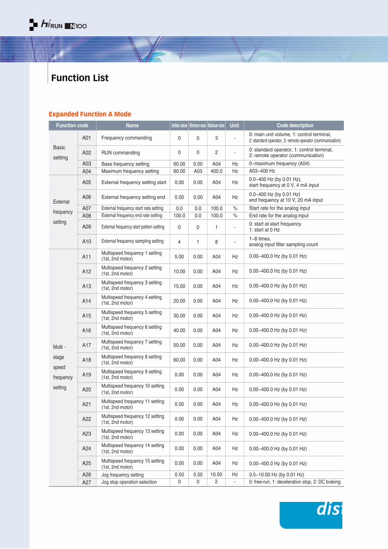
Function List
General Specifications / Function List 08 09
Monitor
Setting
Expanded
function
d01
Function code Name Unit Code descriptionInitial value Minimum value Maximum value
d02
d03
d04
d05
d06
d07
d08
d09
d10
d11
d12
d13
d14
d15
d16
d17
F01
F02
F03
F04
A--
b- -
C--
S--
H--
-
-
-
-
-
-
-
-
-
-
-
-
-
-
-
60.00 0.00 400.0 Hz
0.1 3000 sec
0.1 3000 sec
0
-
-
-
-
-
0
-
-
-
-
-
1
-
-
-
-
-
-
-
-
-
-
-
0.00
0.0
0
-
0
-
-
0.00
0
0
0
0
-
-
-
-
0
400.0
99.9
-
-
100
-
-
-
-
9999
59
-
-
-
-
-
9999
Hz
A
V
-
%
-
-
-
W
Hr
min
V
-
-
-
-
-
0.00~99.99,100.0~400.0 Hz, "Hz" LED on
0.0~99.9 A display, "A" LED on
Output voltage display (V)
"F": forward run, "r": reverse run, "": stop
0~100% display, effective at PID function selection
Intelligent input terminal 1~6
Intelligent output terminal 1~2, alarm terminal
Scale factor (b14) × frequency data
Displays power consumption at inverter start (W)
Inverter operating accumulation time
Inverter real operating time
Display the inverter DC link voltage (V)
Present trip event
Previous 1 trip event
Previous 2 trip events
Previous 3 trip events
Trip accumulation count
0.00~99.99 Hz (by 0.01 Hz)
100.0~400.0 Hz (by 0.1 Hz)
0.1~999.9 sec (by 0.1 sec)
1000~3000 sec (by 1 sec)
0.1~999.9 sec (by 0.1 sec)
1000~3000 sec (by 1 sec)
0: forward , 1: reverse
Setting range: A01~A65
Setting range: b01~b17
Setting range: C01~C23
Setting range: S01~S32
Setting range: H01~H15
10.030.0
10.030.01)
1)
Output frequency monitor
Output current monitor
Output voltage monitor
Rotation direction monitor
PID feedback monitor
Input terminal status monitor
Output terminal status monitor
Scaled output frequency monitor
Power consumption monitor
Operating time accumulation monitor
Real operating time monitor
DC link voltage
Trip event monitor
Trip history 1 monitor
Trip history 2 monitor
Trip history 3 monitor
Trip count
Output frequency setting
Acceleration time 1 setting
Deceleration time 1 setting
Rotation direction setting
Basic setting functions
Fine tuning functions
Terminal setting functions
Second motor setting functions
Sensorless vector setting functions
Monitor Mode / Basic Setting Mode
※ 1) 5.5kW, 7.5kW
Function List
Expanded Function A Mode
Function code Name Initial value Minimum value Maximum value Unit Code description
A01
A02
A05
A06
A07A08
A09
A10
A11
A12
A13
A14
A15
A16
A17
A18
A19
A20
A21
A22
A23
A24
A25
A26A27
A03A04
0
0
0
0
3
2
-
-
0.00 0.00 A04 Hz
0.00 0.00 A04 Hz
0.0100.0
0.00.0
100.0100.0
%%
0
4
5.00
10.00
15.00
20.00
30.00
40.00
50.00
60.00
0.00
0.00
0.00
0.00
0.00
0.00
0.00
1
8
A04
A04
A04
A04
A04
A04
A04
A04
A04
A04
A04
A04
A04
A04
A04
-
-
Hz
Hz
Hz
Hz
Hz
Hz
Hz
Hz
Hz
Hz
Hz
Hz
Hz
Hz
Hz
0
1
0.00
0.00
0.00
0.00
0.00
0.00
0.00
0.00
0.00
0.00
0.00
0.00
0.00
0.00
0.00
0.500
0.500
60.0060.00
0.00A03
A04400.0
HzHz
10.002
Hz-
0: main unit volume, 1: control terminal, 2: standard operator, 3: remote operator (communication)
0: standard operator, 1: control terminal, 2: remote operator (communication)
0~maximum frequency (A04)A03~400 Hz
0.0~400 Hz (by 0.01 Hz),start frequency at 0 V, 4 mA input
0.0~400 Hz (by 0.01 Hz)end frequency at 10 V, 20 mA input
Start rate for the analog inputEnd rate for the analog input
0: start at start frequency 1: start at 0 Hz
1~8 times, analog input filter sampling count
0.00~400.0 Hz (by 0.01 Hz)
0.00~400.0 Hz (by 0.01 Hz)
0.00~400.0 Hz (by 0.01 Hz)
0.00~400.0 Hz (by 0.01 Hz)
0.00~400.0 Hz (by 0.01 Hz)
0.00~400.0 Hz (by 0.01 Hz)
0.00~400.0 Hz (by 0.01 Hz)
0.00~400.0 Hz (by 0.01 Hz)
0.00~400.0 Hz (by 0.01 Hz)
0.00~400.0 Hz (by 0.01 Hz)
0.00~400.0 Hz (by 0.01 Hz)
0.00~400.0 Hz (by 0.01 Hz)
0.00~400.0 Hz (by 0.01 Hz)
0.00~400.0 Hz (by 0.01 Hz)
0.00~400.0 Hz (by 0.01 Hz)
0.5~10.00 Hz (by 0.01 Hz)0: free-run, 1: deceleration stop, 2: DC braking
Frequency commanding
RUN commanding
Base frequency settingMaximum frequency setting
External frequency setting start
External frequency setting end
External frequency start rate settingExternal frequency end rate setting
External frequency start pattern setting
External frequency sampling setting
Multispeed frequency 1 setting(1st, 2nd motor)
Multispeed frequency 2 setting(1st, 2nd motor)
Multispeed frequency 3 setting(1st, 2nd motor)
Multispeed frequency 4 setting(1st, 2nd motor)
Multispeed frequency 5 setting(1st, 2nd motor)
Multispeed frequency 6 setting(1st, 2nd motor)
Multispeed frequency 7 setting(1st, 2nd motor)
Multispeed frequency 8 setting(1st, 2nd motor)
Multispeed frequency 9 setting(1st, 2nd motor)
Multispeed frequency 10 setting(1st, 2nd motor)
Multispeed frequency 11 setting(1st, 2nd motor)
Multispeed frequency 12 setting(1st, 2nd motor)
Multispeed frequency 13 setting(1st, 2nd motor)
Multispeed frequency 14 setting(1st, 2nd motor)
Multispeed frequency 15 setting(1st, 2nd motor)
Jog frequency setting Jog stop operation selection
Basic
setting
External
frequency
setting
Multi -
stage
speed
frequency
setting

Function List 10 11
Function code
V/f charac-teristic
DCbraking
Upper/lower limit jump frequenc y
PID control
AutomaticVoltageRegulation(AVR)
Acceleration/deceleration setting
Name Initial value Minimum value Maximum value Unit Code description
A28
A29
A30
A31
A32
A33
A34
A35
A36
A37
A38
A39
A40
A41
A42
A43
A44
A45
A46
A47
A48
A49
A50
A51
A52
A53
A54
A55
A56
A57
A58
A59
A60
0
5.0
10.0
0
100.0
0
0.50
0.0
10.0
0.0
0.00
0.00
0.00
0.00
0.00
0.00
0.00
0.00
0
10.0
10.0
0.0
100.0
0
0
0
0.0
0.0
0
20.0
0
0.00
0.0
0.0
0.0
0.00
0.00
0.00
0.00
0.00
0.00
0.00
0.00
0
0.1
0.0
0.0
0.1
0
0
1
50.0
100.0
2
100.0
1
10.00
5.0
50.0
10.0
400.0
400.0
400.0
10.00
400.0
10.00
400.0
10.00
1
100.0
100.0
100.0
1000
1
2
-
%
%
-
%
-
Hz
sec
%
sec
Hz
Hz
Hz
Hz
Hz
Hz
Hz
Hz
-
%
sec
sec
-
-
-
220
38010.030.0
0
0.00
0.00
0
0
0.0
100.0
0.0
100.0
0
200
380
0.1
0.1
0
0.00
0.00
0
0
-10.0
0.0
-10.0
0.0
0
240
480
3000
3000
1
400.0
400.0
2
2
10.0
200.0
10.0
200.0
1
sec
sec
-
Hz
Hz
-
-
-
-
-
-
-
V
0: manual torque boost, 1: automatic torque boost
Manual torque boost voltage setting
Manual torque boost frequency setting
0: constant torque, 1: reduced torque (1.7), 2: sensorless vector control
20~100%
0: disable, 1: enable
0.50~10.00 Hz (by 0.01 Hz)
0.0~5.0 sec (by 0.1 sec), free run time
0~50%, by 1%
0.0~10.0 sec (by 0.1 sec)
A39~A04 (by 0.01 Hz)
0.00~A38 (by 0.01 Hz)
0.00~400.0 Hz (by 0.01 Hz)
0.00~10.00 Hz (by 0.01 Hz)
0.00~400.0 Hz (by 0.01 Hz)
0.00~10.00 Hz (by 0.01 Hz)
0.00~400.0 Hz (by 0.01 Hz)
0.00~10.00 Hz (by 0.01 Hz)
0: PID control off, 1: PID control on
0.1~100.0% (by 0.1 sec)
0.0~100 sec (by 0.1 sec)
0.0~100 sec (by 0.1 sec)
0.1~1000.0 (by 0.1 sec)
0: current input, 1: voltage input
0: constant on, 1: constant off, 2: off during deceleration
0.1~999.9 sec (by 0.1 sec)1000~3000 sec (by 1 sec)
0: terminal (2CH), 1: transition frequency (A57, A58)
0.00~400.0 Hz (by 0.01 Hz)
0.00~400.0 Hz (by 0.01 Hz)
0: linear, 1: S-curve, 2: U-curve
0: linear, 1: S-curve, 2: U-curve
Voltage offset
Voltage gain
Current offset
Current gain
0: 5 V input, 1: 10 V input
200/220/230/240 (200-V class)380/400/415/440/460/480 (400-V class)
Torque boost mode selection
Manual torque boost voltage setting
Manual torque boost frequency setting
V/F characteristic curve selection
Output voltage gain setting
DC braking function selection
DC braking frequency setting
DC braking output delay time setting
DC braking force setting
DC braking time setting
Frequency upper limit setting
Frequency lower limit setting
Jump frequency setting 1
Jump frequency band-width setting 1
Jump frequency setting 2
Jump frequency band-width setting 2
Jump frequency setting 3
Jump frequency band-width setting 3
PID function selection
PID P gain setting
PID I gain setting
PID D gain setting
PID scale rate setting
PID feedback input method setting
AVR function selection
Motor input voltage setting
2-stage acceleration time setting
2-stage deceleration time setting
2-stage accel./decel. switching method setting
Acceleration transition frequency setting
Deceleration transition frequency setting
Acceleration pattern setting
Deceleration pattern setting
Voltage signal offset setting
Voltage signal gain setting
Current signal offset setting
Current signal gain setting
External voltage input selection
Input signal adjustment
A61
A62
A63
A64
A65
1)
10.030.01)
※ 1) 5.5kW, 7.5kW
Function List
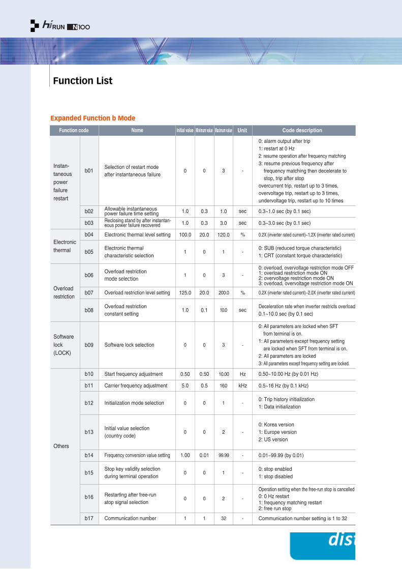
Expanded Function b Mode
Function code
Softwarelock(LOCK)
Name Initial value Minimum value Maximum value Unit Code description
b01
b02
b03
b04
b10
b11
b14
b15
b16
b17
b12
b13
b08
b09
b06
b05
0
0
1.0
1.0
100.0
125.0
0.50
5.0
1.00
1
1
1
1.0
0
0
0
0
0
0
0.3
0.3
20.0
20.0
0.50
0.5
0.01
1
0
0
0.1
0
0
0
0
3
3
1.0
3.0
120.0
200.0
10.00
16.0
99.99
1
3
10.0
1
1
2
2
-
-
sec
sec
%
%
Hz
kHz
-
-
-
-
sec
-
-
-
-
0: alarm output after trip1: restart at 0 Hz2: resume operation after frequency matching3: resume previous frequency after
frequency matching then decelerate to stop, trip after stop
overcurrent trip, restart up to 3 times, overvoltage trip, restart up to 3 times, undervoltage trip, restart up to 10 times
0.3~1.0 sec (by 0.1 sec)
0.3~3.0 sec (by 0.1 sec)
0.2X (inverter rated current)~1.2X (inverter rated current)
0.2X (inverter rated current)~2.0X (inverter rated current)
0.50~10.00 Hz (by 0.01 Hz)
0.5~16 Hz (by 0.1 kHz)
0.01~99.99 (by 0.01)
Communication number setting is 1 to 32
0: stop enabled1: stop disabled
Operation setting when the free-run stop is cancelled0: 0 Hz restart1: frequency matching restart2: free run stop
0: Trip history initialization1: Data initialization
0: Korea version1: Europe version2: US version
0: SUB (reduced torque characteristic)1: CRT (constant torque characteristic)
0: overload, overvoltage restriction mode OFF1: overload restriction mode ON2: overvoltage restriction mode ON 3: overload, overvoltage restriction mode ON
Deceleration rate when inverter restricts overload0.1~10.0 sec (by 0.1 sec)
0: All parameters are locked when SFT from terminal is on.
1: All parameters except frequency setting are locked when SFT from terminal is on.
2: All parameters are locked3: All parameters except frequency setting are locked.
Selection of restart mode after instantaneous failure
Allowable instantaneous power failure time settingReclosing stand by after instantan-eous power failure recovered
Electronic thermal level setting
Electronic thermal characteristic selection
Overload restriction mode selection
Overload restriction level setting
Start frequency adjustment
Carrier frequency adjustment
Overload restriction constant setting
Initialization mode selection
Stop key validity selectionduring terminal operation
Restarting after free-run stop signal selection
Initial value selection (country code)
Software lock selection
Frequency conversion value setting
Communication number
b07
Instan-taneous powerfailure restart
Electronic thermal
Overload restriction
Others
32
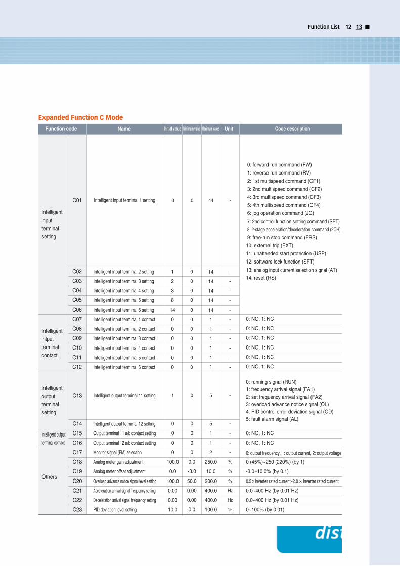
Function List 12 13
Function code
Intelligent output terminal contact
Name Initial value Minimum value Maximum value Unit Code description
C01
C02
C03
C04
C05
C06
C07
C08
C09
C10
C11
C12
C13
C14
C15
C16
C17
C18
C19
C20
C21
C22
C23
0 0 14 -Intelligent input terminal 1 setting
Intelligent input terminal 2 setting
Intelligent input terminal 3 setting
Intelligent input terminal 4 setting
Intelligent input terminal 5 setting
Intelligent input terminal 6 setting
Intelligent input terminal 1 contact
Intelligent input terminal 2 contact
Intelligent input terminal 3 contact
Intelligent input terminal 4 contact
Intelligent input terminal 5 contact
Intelligent input terminal 6 contact
Intelligent output terminal 11 setting
Intelligent output terminal 12 setting
Output terminal 11 a/b contact setting
Output terminal 12 a/b contact setting
Monitor signal (FM) selection
Analog meter gain adjustment
Analog meter offset adjustment
Overload advance notice signal level setting
Acceleration arrival signal frequency setting
Deceleration arrival signal frequency setting
PID deviation level setting
1
2
3
8
14
0
0
0
0
0
0
1
0
0
0
0
100.0
0.0
100.0
0.00
0.00
10.0
0
0
0
0
0.0
-3.0
50.0
0.00
0.00
0.0
5
1
1
2
250.0
10.0
200.0
400.0
400.0
100.0
-
-
-
-
%
%
%
Hz
Hz
%
0: NO, 1: NC
0: NO, 1: NC
0: output frequency, 1: output current, 2: output voltage
0 (45%)~250 (220%) (by 1)
-3.0~10.0% (by 0.1)
0.5×inverter rated current~2.0× inverter rated current
0.0~400 Hz (by 0.01 Hz)
0.0~400 Hz (by 0.01 Hz)
0~100% (by 0.01)
0 5 -
0: NO, 1: NC
0: NO, 1: NC
0: NO, 1: NC
0: NO, 1: NC
0: NO, 1: NC
0: NO, 1: NC
0: running signal (RUN)1: frequency arrival signal (FA1)2: set frequency arrival signal (FA2)3: overload advance notice signal (OL)4: PID control error deviation signal (OD)5: fault alarm signal (AL)
0
0
0
0
0
0
0
0
0
0
0
14
14
14
14
14
1
1
1
1
1
1
-
-
-
-
-
-
-
-
-
-
-
0: forward run command (FW)
1: reverse run command (RV)
2: 1st multispeed command (CF1)
3: 2nd multispeed command (CF2)
4: 3rd multispeed command (CF3)
5: 4th multispeed command (CF4)
6: jog operation command (JG)
7: 2nd control function setting command (SET)
8: 2-stage acceleration/deceleration command (2CH)
9: free-run stop command (FRS)
10: external trip (EXT)
11: unattended start protection (USP)
12: software lock function (SFT)
13: analog input current selection signal (AT)
14: reset (RS)
Intelligentinput terminalsetting
Intelligentintput terminalcontact
Intelligentoutput terminalsetting
Others
Expanded Function C Mode
Function List
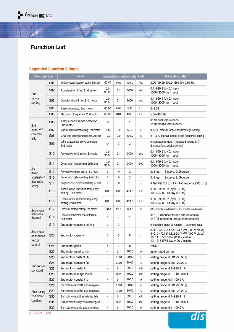
Expanded Function S Mode
S01
S02
S03
S04
S05
S07
S08
S09
S12
S13
S14
S10
S11
S17
S18
S19
S20
S21
S22
S23
S24
S25
S26
S27
S28
S29
S30
S31
S32
S15
S16
S06
10.030.01)
10.030.01)
10.030.01)
10.030.01)
60.00
60.00
5.0
10.0
0
0
0
0
0
0
0
100.0
1
0
4
-
-
-
-
-
-
-
-
-
-
-
0.1
0.001
0.001
0.1
0.01
0.1
0.001
0.001
0.1
0.01
0.1
100.0
30.00
20.00
999.9
100.0
100.0
30.00
20.00
999.9
100.0
100.0
0
0.00
0.00
0
60.00
0.1
0.1
0.00
S04
0.0
0.0
0
20.0
0
0
2
0
0.00
0.00
0.1
0.1
0
0.00
3000
3000
S05
400.0
50.0
100.0
2
2
2
1
120.0
1
9
8
1
400.0
400.0
3000
3000
1
400.0
sec
sec
Hz
Hz
%
%
-
-
-
-
%
-
-
-
-
A
Ω
Ω
mH
mH
A
Ω
Ω
mH
mH
A
Hz
Hz
sec
sec
-
Hz 0.00~99.99,100.0~S05 (by 0.01 Hz)
0.1~999.9 (by 0.1 sec) 1000~3000 (by 1 sec)
0.1~999.9 (by 0.1 sec)1000~3000 (by 1 sec)
Multistage speed frequency setting, 2nd motor
Acceleration time, 2nd motor
Deceleration time, 2nd motor
Base frequency, 2nd motor
Maximum frequency, 2nd motor
Manual torque boost setting , 2nd motor
Manual torque boost frequency adjustment, 2nd motor
V/f characteristic curve selection, 2nd motor
Acceleration time 2 setting, 2nd motor
Deceleration time 2 setting, 2nd motor
Acceleration pattern setting, 2nd motor
Deceleration pattern setting, 2nd motor
Electronic thermal setting, 2nd motor
Electronic thermal characteristic,2nd motor
2nd motor constant setting
2nd motor capacity
2nd motor poles
2nd motor rated current
2nd motor constant R1
2nd motor constant R2
2nd motor constant L
2nd motor leakage factor
2nd motor constant Io
2nd motor constant R1 auto-tuning data
2nd motor constant R2 auto-tuning data
2nd motor constant L auto-tuning data
2nd motor constant leakage factor auto-tuning data
2nd motor constant Io auto-tuning data
2-stage accel./decel. transition method setting, 2nd motor
Acceleration transition frequencysetting , 2nd motor
Deceleration transition frequencysetting, 2nd motor
Torque boost mode selection,2nd motor
0~S05
S04~400 Hz
0~50%, manual torque boost voltage setting
0~100%, manual torque boost frequency setting
0: constant torque, 1: reduced torque (1.7)2: sensorless vector control
0: linear, 1:S-curve, 2: U-curve
0: linear, 1:S-curve, 2: U-curve
0: terminal (2CH), 1: transition frequency (S15, S16)
0.2×inverter rated current~1.2×inverter rated current
0: SUB (reduced torque characteristic) 1: CRT (constant torque characteristic)
0: standard motor constants, 1: auto tune data
0~4: 0.4/0.75/.1.5/2.2/3.7 kW (200 V class) 5~9: 0.4/0.75/.1.5/2.2/3.7 kW (400 V class)10, 11: 5.5/7.5 kW (200 V class)12, 13: 5.5/7.5 kW (400 V class)
2/4/6/8
motor rated current
setting range: 0.001~30.00 Ω
setting range: 0.001~20.00 Ω
setting range: 0.1~999.9 mH
setting range: 0.01~100.0 mH
setting range: 0.1~100.0 A
setting range: 0.001~30.00 Ω
setting range: 0.001~20.00 Ω
setting range: 0.1~999.9 mH
setting range: 0.01~100.0 mH
setting range: 0.1~100.0 A
0.00~99.99 Hz (by 0.01 Hz)100.0~400.0 Hz (by 0.1 Hz)
0.00~99.99 Hz (by 0.01 Hz)100.0~400.0 Hz (by 0.1 Hz)
0.1~999.9 (by 0.1 sec)1000~3000 (by 1 sec)
0.1~999.9 (by 0.1 sec)1000~3000 (by 1 sec)
0: manual torque boost1: automatic torque boost
2ndmotor setting
2nd motor V/F chracter-istic
2nd motor acceleration/deceleration setting
2nd motorelectronicthermal
2nd motor sensorless vectorcontrol
2nd motor constant
Auto-tuning 2nd motor constant
Function code Name Initial value Minimum value Maximum value Unit Code description
※ 1) 5.5kW, 7.5kW
Function List / Protective Functions 14 15
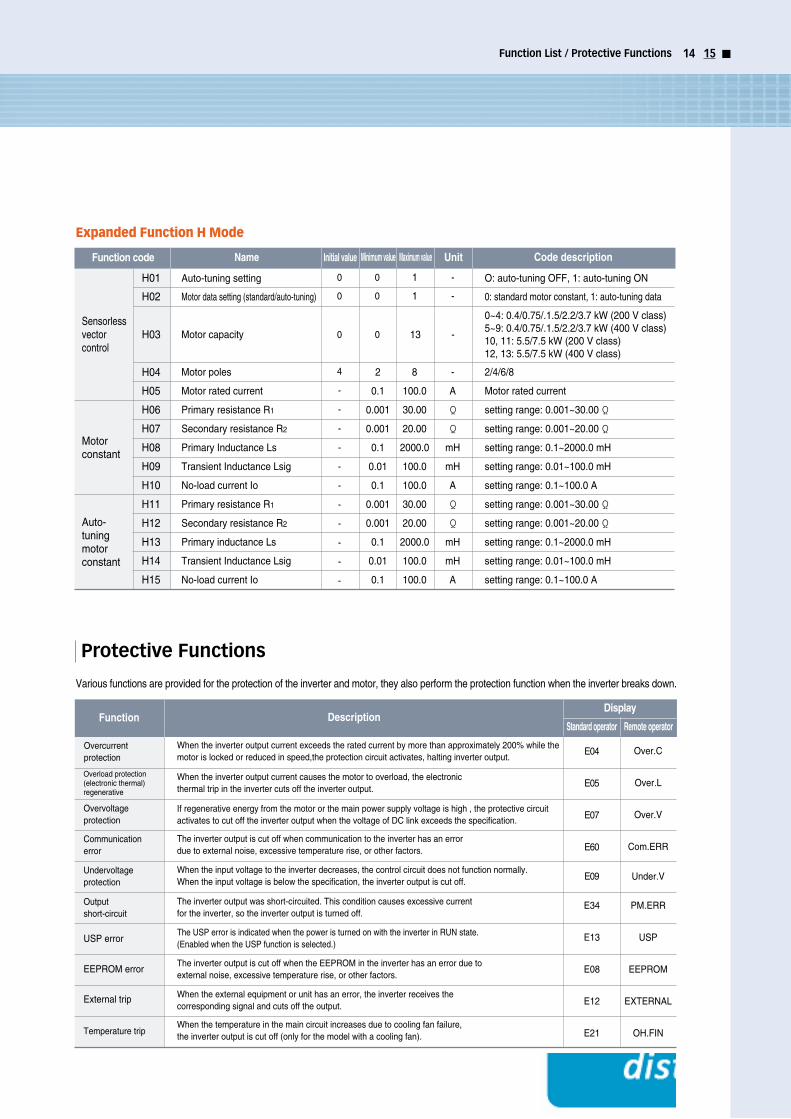
Expanded Function H Mode
Various functions are provided for the protection of the inverter and motor, they also perform the protection function when the inverter breaks down.
Motor poles
Motor rated current
Primary resistance R1
Secondary resistance R2
Primary Inductance Ls
Transient Inductance Lsig
No-load current Io
Primary resistance R1
Secondary resistance R2
Primary inductance Ls
Transient Inductance Lsig
No-load current Io
Auto-tuning setting
Motor data setting (standard/auto-tuning)
Motor capacity
H01
H02
H03
H04
H05
H06
H07
H08
H09
H10
H11
H12
H13
H14
H15
0
0
0
0
1
1
-
-
0 0 13 -
4
-
-
-
-
-
-
-
-
-
-
-
2
0.1
0.001
0.001
0.1
0.01
0.1
0.001
0.001
0.1
0.01
0.1
8
100.0
30.00
20.00
2000.0
100.0
100.0
30.00
20.00
2000.0
100.0
100.0
-
A
Ω
Ω
mH
mH
A
Ω
Ω
mH
mH
A
2/4/6/8
Motor rated current
setting range: 0.001~30.00 Ω
setting range: 0.001~20.00 Ω
setting range: 0.1~2000.0 mH
setting range: 0.01~100.0 mH
setting range: 0.1~100.0 A
setting range: 0.001~30.00 Ω
setting range: 0.001~20.00 Ω
setting range: 0.1~2000.0 mH
setting range: 0.01~100.0 mH
setting range: 0.1~100.0 A
O: auto-tuning OFF, 1: auto-tuning ON
0: standard motor constant, 1: auto-tuning data
0~4: 0.4/0.75/.1.5/2.2/3.7 kW (200 V class) 5~9: 0.4/0.75/.1.5/2.2/3.7 kW (400 V class)10, 11: 5.5/7.5 kW (200 V class)12, 13: 5.5/7.5 kW (400 V class)
Sensorless vectorcontrol
Motorconstant
Auto-tuning motorconstant
Function code Name Initial value Minimum value Maximum value Unit Code description
Overcurrentprotection
Overload protection (electronic thermal)regenerative
Overvoltageprotection
Communication error
Undervoltageprotection
Output short-circuit
USP error
EEPROM error
External trip
Temperature trip
FunctionDisplay
Standard operator Remote operatorDescription
When the inverter output current exceeds the rated current by more than approximately 200% while themotor is locked or reduced in speed,the protection circuit activates, halting inverter output.
When the inverter output current causes the motor to overload, the electronic thermal trip in the inverter cuts off the inverter output.
If regenerative energy from the motor or the main power supply voltage is high , the protective circuitactivates to cut off the inverter output when the voltage of DC link exceeds the specification.
The inverter output is cut off when communication to the inverter has an error due to external noise, excessive temperature rise, or other factors.
The inverter output was short-circuited. This condition causes excessive current for the inverter, so the inverter output is turned off.
The USP error is indicated when the power is turned on with the inverter in RUN state. (Enabled when the USP function is selected.)
The inverter output is cut off when the EEPROM in the inverter has an error due to external noise, excessive temperature rise, or other factors.
When the external equipment or unit has an error, the inverter receives the corresponding signal and cuts off the output.
When the temperature in the main circuit increases due to cooling fan failure, the inverter output is cut off (only for the model with a cooling fan).
When the input voltage to the inverter decreases, the control circuit does not function normally.When the input voltage is below the specification, the inverter output is cut off.
E04
E05
E07
E60
E09
E34
E13
E08
E12
E21
Over.C
Over.L
Over.V
Com.ERR
Under.V
PM.ERR
USP
EEPROM
EXTERNAL
OH.FIN
Protective Functions

Terminal Functions
Main Circuit Terminal
Control Circuit Terminal
R.S.T
U.V.W
P.RB
Main power supply input terminal
Inverter output terminal
External resistor connection terminal
Connects the input power supply 220/440 V
Connects to the motor
Connects the braking resistor (option)
Connects the die-casting (to prevent
electric shock and reduce noise)Ground connection terminal
Terminal name FunctionTerminal symbol
Input signal
Monitor signal
Frequency
command
signal
Output
signal
Trip alarm
output
signal
P24
6
5
4
3
2
1
CM1
RS
2CH
CF2
CF1
RV
FW
FA1, 2
RUN
FM
H
O
OI
L
11
12
AL2
AL1
AL0
CM2
Power terminal for input signals 24VDC±10%, 35 mA
Contact rating:
AC 250 V 2.5 A (resistor load)
0.2 A (induction load)
DC 30 V 3.0 A (resistor load)
0.7 A (induction load)
Contact input:
Closed: on (operating)
Open: off (stop)
Minimum on time: over 12 ms
Common terminals for input or monitor signal
Output frequency meter, output current meter, output voltage meter
Power supply for frequency setting
Voltage frequency command signal
Current frequency command signal
Common terminal for frequency command
Intelligent output terminal;
Run status signal (RUN),frequency arrival signal (FA1),
set frequency arrival signal (FA2), overload advance notice signal (OL),
PID error deviation signal (OD), and alarm signal (AL)
Common terminal for output signals
Alarm output signals:
At normal status,power off (initial setting value): AL0-AL2 (closed)
At abnormal status : AL0-AL1 (closed)
Forward run command (FW), reverse run command (RV),
Multi-speed commands 1~4 (CF1~4), 2-stage accel./decel. command (2CH),
Reset (RS), free run stop (FRS), external trip (EXT),
Second control function setting (SET), terminal software lock (SFT),
Unattended start protection (USP),
Current input selection (AT), jog operation (JG)
Signal Terminal symbol Terminal name Terminal function
0~5VDC
0~5VDC (standard), 0~10VDC, input impedance 10 kΩ
4~20 mA, input impedance 250 Ω
Maximum 27 VDC, 50 mA
Analog frequency meter
※ Please change terminal No.5 to No.13 AT(current input selection) in case of 4~20mA input.
※

Standard Connection Diagram
Terminal Functions / Standard Connection Diagram 16 17
Terminal Connection Diagram
S
COM
JB
CM1JA
CM1
DC24VP24
Inveter
+3 1
2
23
1-
Sink type
COM
S
JB
CM1JA
CM1
DC24VP24
Inveter
+3 1
2
23
1-
Source type
S
COM
JB
CM1JA
CM1
DC24VP24
Inverter
+3
1
2
23
1-
+-
DC24V
Sink type
COM
S
JB
CM1JA
CM1
DC24VP24
Inverter
+3
1
2
23
1-
+-
DC24V
Source type
PLC Connection
Input Terminal Connection Diagram In case of using internal power
In case of using external power
※ 1) In case of changing terminal No.5 to No. 13 AT(current input selection) on : 4~20mA selection / off : Volume selection
2) Please refer to page 24.
2)
1)
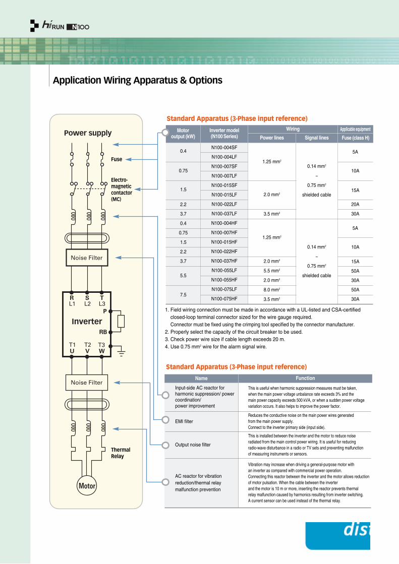
Application Wiring Apparatus & Options
1. Field wiring connection must be made in accordance with a UL-listed and CSA-certifiedclosed-loop terminal connector sized for the wire gauge required. Connector must be fixed using the crimping tool specified by the connector manufacturer.
2. Properly select the capacity of the circuit breaker to be used.3. Check power wire size if cable length exceeds 20 m.4. Use 0.75 mm2 wire for the alarm signal wire.
Fuse
ThermalRelay
Electro-magneticcontactor(MC)
Name Function
Input-side AC reactor forharmonic suppression/ powercoordination/power improvement
This is useful when harmonic suppression measures must be taken, when the main power voltage unbalance rate exceeds 3% and the main power capacity exceeds 500 kVA, or when a sudden power voltagevariation occurs. It also helps to improve the power factor.
Reduces the conductive noise on the main power wires generated from the main power supply. Connect to the inverter primary side (input side).
This is installed between the inverter and the motor to reduce noise radiated from the main control power wiring. It is useful for reducing radio-wave disturbance in a radio or TV sets and preventing malfunction of measuring instruments or sensors.
Vibration may increase when driving a general-purpose motor with an inverter as compared with commercial power operation. Connecting this reactor between the inverter and the motor allows reduction of motor pulsation. When the cable between the inverter and the motor is 10 m or more, inserting the reactor prevents thermal relay malfunction caused by harmonics resulting from inverter switching. A current sensor can be used instead of the thermal relay.
EMI filter
Output noise filter
AC reactor for vibration reduction/thermal relay malfunction prevention
Standard Apparatus (3-Phase input reference)
Standard Apparatus (3-Phase input reference)
Motor output (kW)
0.4
0.75
1.5
2.2
3.7
0.4
0.75
1.5
2.2
3.7
N100-004SF
N100-004LF
N100-007SF
N100-007LF
N100-015SF
N100-015LF
N100-022LF
N100-037LF
N100-004HF
N100-007HF
N100-015HF
N100-022HF
N100-037HF
N100-055LF
N100-055HF
N100-075LF
N100-075HF
1.25 mm2
2.0 mm2
3.5 mm2
0.14 mm2
~
0.75 mm2
shielded cable
5A
30A
20A
15A
10A
5A
15A
50A
30A
50A
30A
10A0.14 mm2
~
0.75 mm2
shielded cable
2.0 mm2
5.5 mm2
2.0 mm2
8.0 mm2
3.5 mm2
1.25 mm2
Inverter model(N100 Series)
Wiring Applicable equipment
Fuse (class H)Power lines Signal lines
5.5
7.5
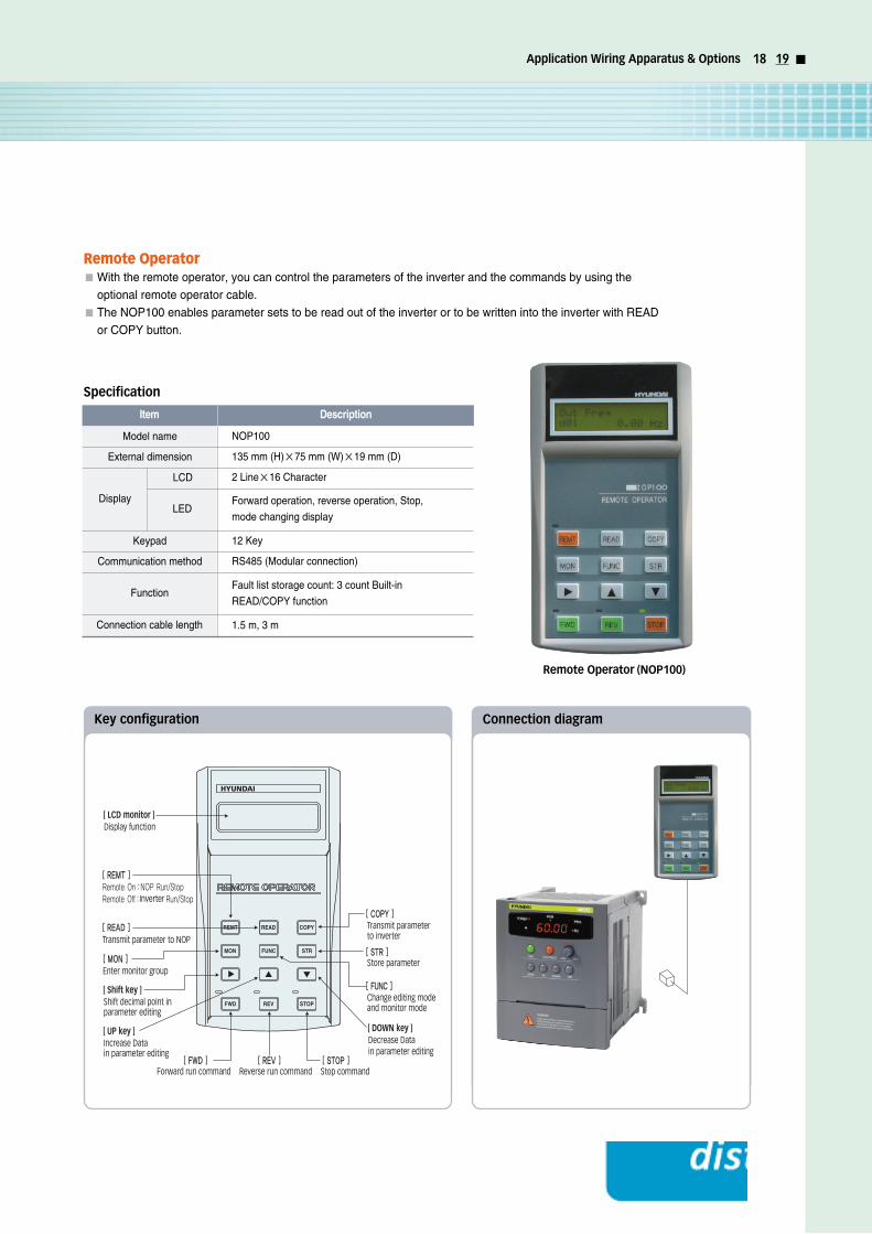
Application Wiring Apparatus & Options 18 19
Remote Operator With the remote operator, you can control the parameters of the inverter and the commands by using the
optional remote operator cable.
The NOP100 enables parameter sets to be read out of the inverter or to be written into the inverter with READ
or COPY button.
Display function
Decrease Datain parameter editing
Shift decimal point in parameter editing
Increase Datain parameter editing
Transmit parameter to NOP
Enter monitor group
Forward run command Reverse run command Stop command
Transmit parameter to inverter
Store parameter
Change editing modeand monitor mode
Inverter
Specification
Remote Operator (NOP100)
Item Description
NOP100
135 mm (H)×75 mm (W)×19 mm (D)
2 Line×16 Character
12 Key
RS485 (Modular connection)
Fault list storage count: 3 count Built-in
READ/COPY function
Forward operation, reverse operation, Stop,
mode changing display
1.5 m, 3 m
Model name
External dimension
Keypad
Communication method
Function
Connection cable length
Display
LCD
LED
Key configuration Connection diagram
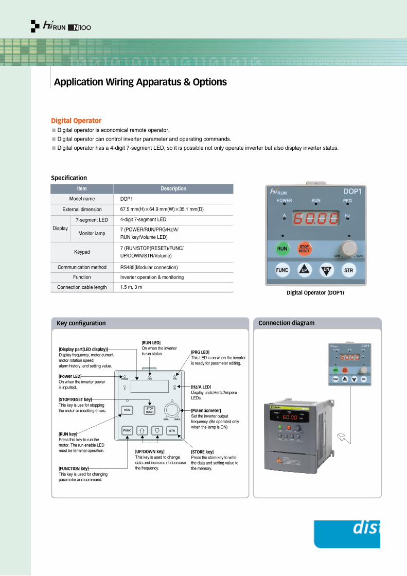
Application Wiring Apparatus & Options
Digital OperatorDigital operator is economical remote operator.
Digital operator can control inverter parameter and operating commands.
Digital operator has a 4-digit 7-segment LED, so it is possible not only operate inverter but also display inverter status.
RUN
FUNC STR
STOPRESET
MIN. MAX.
POWER RUN PRG
A Hz
[STOP/RESET key]This key is use for stopping the motor or resetting errors.
[RUN LED]On when the inverter is run status
[Power LED]On when the inverter power is inputted.
[Display part(LED display)]Display frequency, motor current, motor rotation speed, alarm history, and setting value.
[RUN key]Press this key to run themotor. The run enable LEDmust be terminal operation.
[FUNCTION key]This key is used for changingparameter and command.
[UP/DOWN key]This key is used to changedata and increase of decreasethe frequency.
[STORE key]Press the store key to writethe data and setting value tothe memory.
[Potentiometer]Set the inverter outputfrequency.(Be operated onlywhen the lamp is ON)
[Hz/A LED]Display units Hertz/AmpereLEDs.
[PRG LED]This LED is on when the inverteris ready for parameter editing.
Digital Operator (DOP1)
Key configuration Connection diagram
Specification
Item Description
DOP1
67.5 mm(H)×64.9 mm(W)×35.1 mm(D)
4-digit 7-segment LED
7 (RUN/STOP(RESET)/FUNC/
UP/DOWN/STR/Volume)
Inverter operation & monitoring
7 (POWER/RUN/PRG/Hz/A/
RUN key/Volume LED)
RS485(Modular connection)
External dimension
Model name
Keypad
Communication method
Function
Connection cable length
Display
7-segment LED
Monitor lamp
1.5 m, 3 m
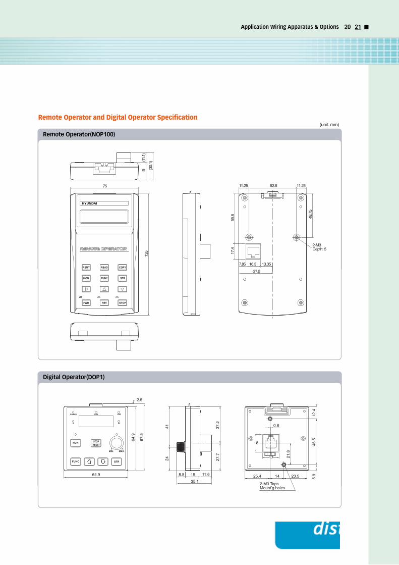
Application Wiring Apparatus & Options 20 21
Remote Operator and Digital Operator Specification
135
19
(30.
1)
75
(11.
1)
11.25 52.5 11.25
48.7
5
55.6
17.4
2-M3Depth: 5
16.37.85 13.35
37.5
Remote Operator(NOP100)
2-M3 Taps Mount’g holes
14
27.7
25.4 5.9
46.5
24
23.5
0.837.2
12.4
21.8
41
64.9
158.564.9 11.6
35.1
17
2.5
67.5
18RUN
FUNC STR
STOPRESET
MIN. MAX.
POWER RUN PRG
A Hz
Digital Operator(DOP1)
(unit: mm)
Application Wiring Apparatus & Options
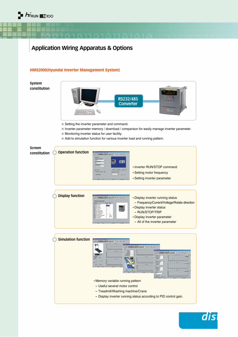
HMS2000(Hyundai Inverter Management System)
RS232/485 Converter
Systemconstitution
Setting the inverter parameter and command.
Inverter parameter memory / download / comparison for easily manage inverter parameter.
Monitoring inverter status for user facility.
Add to simulation function for various inverter load and running pattern.
•Inverter RUN/STOP command
•Setting motor frequency
•Setting inverter parameter
Operation function
•Display inverter running status
- Frequency/Current/Voltage/Rotate direction
•Display inverter status
- RUN/STOP/TRIP
•Display inverter parameter
- All of the inverter parameter
Display function
•Memory variable running pattern
- Useful several motor control
- Treadmill/Washing machine/Crane
- Display inverter running status according to PID control gain.
Simulation function
Screenconstitution
Application Wiring Apparatus & Options 22 23
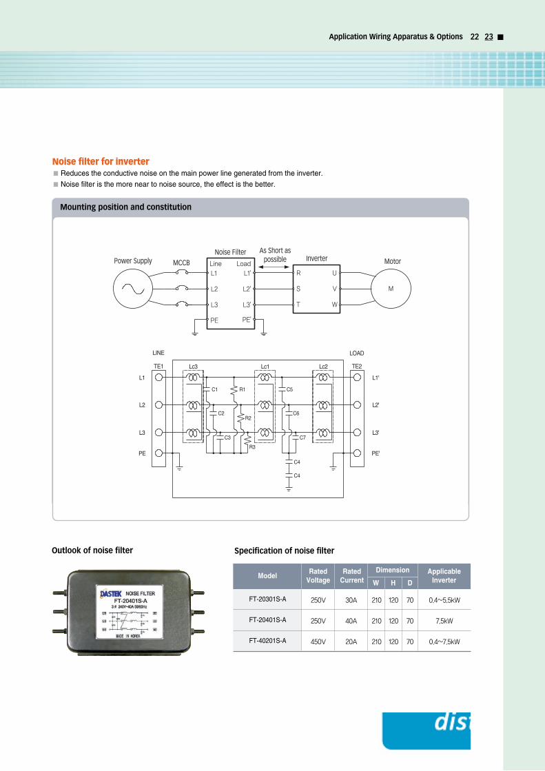
Noise filter for inverterReduces the conductive noise on the main power line generated from the inverter.
Noise filter is the more near to noise source, the effect is the better.
Power SupplyNoise Filter
MCCB
As Short aspossible MotorInverter
Mounting position and constitution
Specification of noise filterOutlook of noise filter
250V
250V
450V
30A
40A
20A
210
210
210
120
120
120
70
70
70
0.4~5.5kW
7.5kW
0.4~7.5kW
FT-20301S-A
FT-20401S-A
FT-40201S-A
ModelRated
VoltageRated
CurrentApplicable
InverterDimension
W H D

Application Wiring Apparatus & Options
Dynamic Braking ResistorDynamic braking uses the case of increase braking torque, frequently ON/OFF and large inertial load.
In case of light load
In case of heavy load
Specification table
1
2
3
4
5
1.5 kW
2.2 kW
3.7 kW
5.5 kW
7.5 kW
50 Ω
50 Ω
35 Ω
17 Ω
17 Ω
0.2 kW
0.3 kW
0.6 kW
1.2 kW
1.2 kW
180 Ω
100 Ω
100 Ω
70 Ω
50 Ω
0.3 kW
0.3 kW
0.6 kW
1.2 kW
1.2 kW
Motor capacity (kW)Resistance Wattage Resistance Wattage
Dynamic braking resistance (200 V class) Dynamic braking resistance (400 V class)
1
2
3
4
5
1.5 kW
2.2 kW
3.7 kW
5.5 kW
7.5 kW
50 Ω
35 Ω
35 Ω
17 Ω
17 Ω
0.2 kW
0.6 kW
1.2 kW
1.8 kW
2.4 kW
180 Ω
100 Ω
100 Ω
70 Ω
50 Ω
0.3 kW
0.6 kW
0.6 kW
1.8 kW
2.4 kW
Motor capacity (kW)Resistance Wattage Resistance Wattage
Dynamic braking resistance (200 V class) Dynamic braking resistance (400 V class)
Instance : 2.6 kWRating : 300 kW
Instance : 3.8 kWRating : 600 kW
Externalresistance
unit
RB0
RB1
RB2
200 W
300 W
600 W
180 Ω±5%
50 Ω±5%
35 Ω±5%
Maximum 10 sec.
Maximum 10 sec.
Maximum 10 sec.
Instance : 0.7 kWRating : 200 kW
Figure 1
Figure 2
Figure 3
Built-in temperature relay inresistance. At disorder hightemperature, “open”(b contact)signal occurred.Rating contact AC 240 V 3 A (R load) 0.2 A (L load)DC 36 V 2 A (R load)
Name Type name Rating capacity Resistance Rating continuous ON time Consuming power Protect overheat Figure
(Fig 1) RB0 Type
(Fig 2) RB1 Type
(Fig 3) RB2 Type
Application Wiring Apparatus & Options 24 25
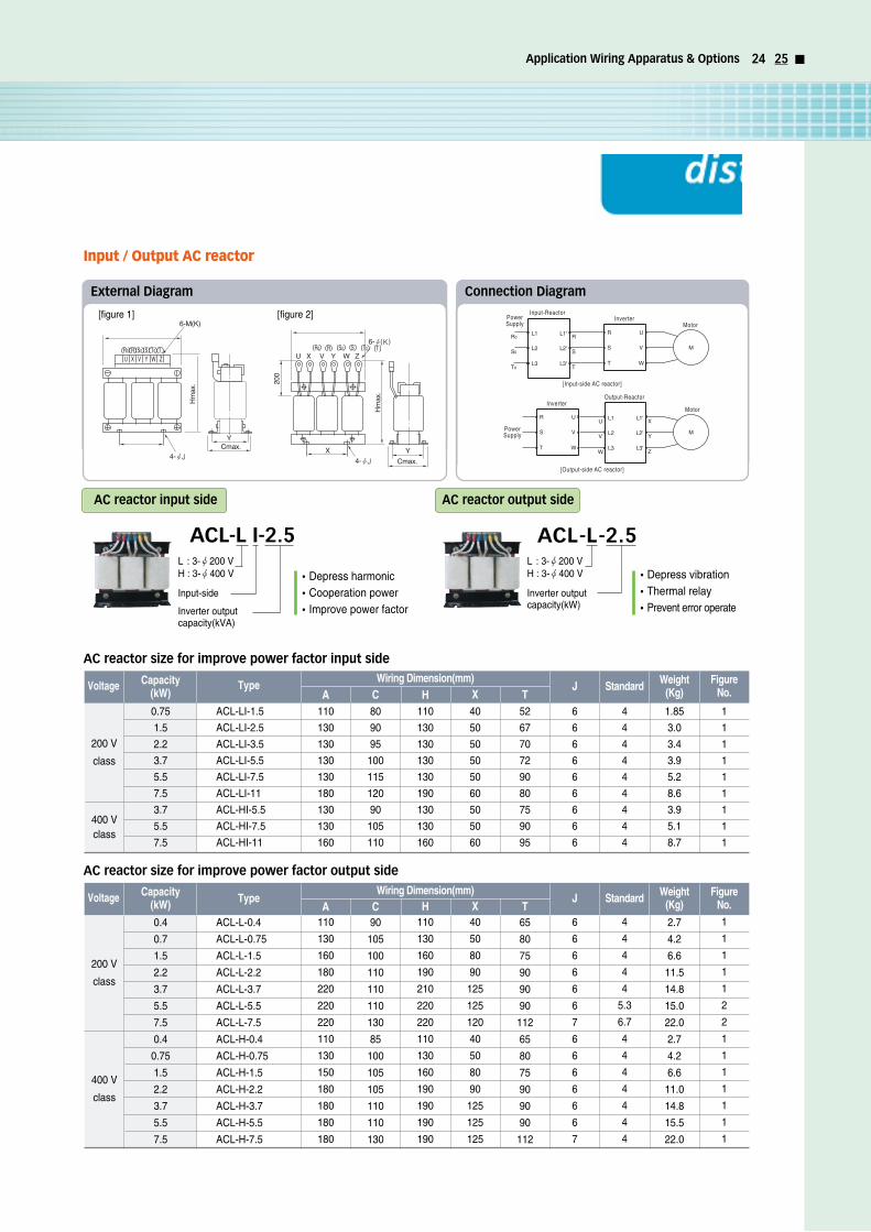
Input / Output AC reactor
AC reactor size for improve power factor input side
200 V
class
400 Vclass
1
1
1
1
1
1
1
1
1
0.75
1.5
2.2
3.7
5.5
7.5
3.7
5.5
7.5
ACL-LI-1.5
ACL-LI-2.5
ACL-LI-3.5
ACL-LI-5.5
ACL-LI-7.5
ACL-LI-11
ACL-HI-5.5
ACL-HI-7.5
ACL-HI-11
110
130
130
130
130
180
130
130
160
80
90
95
100
115
120
90
105
110
110
130
130
130
130
190
130
130
160
40
50
50
50
50
60
50
50
60
52
67
70
72
90
80
75
90
95
6
6
6
6
6
6
6
6
6
4
4
4
4
4
4
4
4
4
1.85
3.0
3.4
3.9
5.2
8.6
3.9
5.1
8.7
Voltage Capacity(kW)
TypeWiring Dimension(mm)
A C H X TJ Standard Weight
(Kg)Figure
No.
PowerSupply
PowerSupply
Input-Reactor
Output-Reactor
[Input-side AC reactor]
[Output-side AC reactor]
Inverter
Inverter
Motor
Motor
Connection DiagramExternal Diagram
AC reactor size for improve power factor output side
200 V
class
400 V
class
1
1
1
1
1
2
2
1
1
1
1
1
1
1
0.4
0.7
1.5
2.2
3.7
5.5
7.5
0.4
0.75
1.5
2.2
3.7
5.5
7.5
ACL-L-0.4
ACL-L-0.75
ACL-L-1.5
ACL-L-2.2
ACL-L-3.7
ACL-L-5.5
ACL-L-7.5
ACL-H-0.4
ACL-H-0.75
ACL-H-1.5
ACL-H-2.2
ACL-H-3.7
ACL-H-5.5
ACL-H-7.5
110
130
160
180
220
220
220
110
130
150
180
180
180
180
90
105
100
110
110
110
130
85
100
105
105
110
110
130
110
130
160
190
210
220
220
110
130
160
190
190
190
190
40
50
80
90
125
125
120
40
50
80
90
125
125
125
65
80
75
90
90
90
112
65
80
75
90
90
90
112
6
6
6
6
6
6
7
6
6
6
6
6
6
7
4
4
4
4
4
5.3
6.7
4
4
4
4
4
4
4
2.7
4.2
6.6
11.5
14.8
15.0
22.0
2.7
4.2
6.6
11.0
14.8
15.5
22.0
Voltage Capacity(kW) Type
Wiring Dimension(mm)A C H X T
J Standard Weight(Kg)
FigureNo.
ACL-L I-2.5L : 3-Ø200 VH : 3-Ø400 V
Input-side
Inverter outputcapacity(kVA)
AC reactor input side
•Depress harmonic•Cooperation power•Improve power factor
ACL-L-2.5L : 3-Ø200 VH : 3-Ø400 V
Inverter outputcapacity(kW)
AC reactor output side
•Depress vibration•Thermal relay•Prevent error operate
[figure 1] [figure 2]

Proper Operation
Before use, be sure to read through the Instruction Manual to insure proper operation.Note that the inverter requires proper electrical wiring; a specialist should carry out the wiring.The inverter in this catalog is designed for general industrial applications. For special applications in fields such as aircraft, outer space,
nuclear power, electrical power, transport vehicles, clinics, and submarine relay equipment, please consult us in advance.For application in a facility where human safety is at stake or serious losses may occur, be sure to program all safety devices to avoid
serious accidents.
The inverter is used for three-phase AC motor.
Operatingfrequency
Torquecharacteristics
Motor loss & temp-erature increase
Noise
Vibration
Powertransmissionmechanism
The overspeed endurance of a general-purpose motor is 120% of the rated speed for 2 minutes (JIS C4004). For operation higher than 60 Hz, it is required to examine the allowable torque of the motor, useful-life of bearings, noise, vibration, etc. In this case, be sure to consult the motor manufacturer as the maximum allowable rpm differs depending on the motor capacity, etc.
The torque characteristics of driving a general-purpose motor with an inverter differ from those of driving it with commercial power (starting torque decreases in particular). Carefully check the load torque characteristic of a connected machine and the driving torque characteristic of the motor.
An inverter-driven general-purpose motor heats up swiftly at lower speeds. Consequently, the torque level permitting continuous use decreaseswith lower motor speeds. Carefully check the torque characteristics.
When run by an inverter, a general-purpose motor generates noise slightly greater than with commercial power.
When run by an inverter at variable speeds, the motor may regenerate vibration, especially because of (a) unbalance of the rotor including a connected machine, or (b) resonance caused by the natural vibration frequency of a mechanical system. Particularly, be careful of (b) when operating a machine previously fitted with a constant speed motor at variable speed.Vibration can be minimized by (1) avoiding resonance points using the frequency jump function of the inverter, (2) using a flexible coupling, or (3) placing a rubber shock absorber beneath the motor base.
Under continuous, low-speed operation, oil lubrication can deteriorate in a power transmission mechanism with an oil-type gear box (gear motor) or reducer. Consult the motor manufacturer for the permissible range of continuous speed. To operate at more than 60 Hz, confirm the machine's ability to withstand the centrifugal force generated.
Application to General-Purpose Motors
A system applying a voltage-type PWM inverter with IGBT can have surge voltage at the motor terminals resulting from the cable constants including the cable length and the wiring method. Depending on the surge current magnification, the motor coil insulation may be degraded. In particular, when a 400-V class motor is used, a longer cable is used, and critical loss can occur. Take the following countermeasures:
(1) Install the LCR filter between the inverter and the motor. (2) Install the AC reactor between the inverter and the motor. (3) Enhance the insulation of the motor coil.
Application to the 400-V Class Motor
Run or stop of the inverter must be done with the keys on the operator panel or through a control circuit terminal.Do not operate by installing a electromagnetic contactor (M) in the main circuit.
When the protective function is operating or the power supply stops, the motor enters the free run stop state. When an emergency stop is required or when the motor should be kept stopped, use the mechanical brake.
A max. of 360 Hz can be selected on the N100 Series. However, a two-pole motor can attain up to approx. 21,600 rpm, which is extremely dangerous. Therefore, carefully make selection and settings by checking the mechanical strength of the motor and connected machines. Consult the motor manufacturer when it is necessary to drive a standard (general-purpose) motor at over 60 Hz. A full line of high-speed motors is available from manufacturer.
Run/Stop
Emergency motor stop
Notes on Use: Drive
High-frequencyrun
Gear motor
A single-phase motor is not suitable for variable-speed operation by inverter drive. Therefore, use a three-phase motor.
The allowable rotation range of continuous drive varies depending on the lubrication method or motor manufacturer. (Particularly where oil lubrication isconcerned, pay attention to the low frequency range). The Hitachi GA/GX/CX gear motors are of a grease lubrication type. Their grease lubricationcapability remains unchanged even if the motor rotating speed decreases.
When using a brake motor, be sure to connect the braking power supply on the primary side of the inverter.Brake motorThere are different kinds of pole-change motors: constant output characteristic type, constant torque characteristic type, etc., and different rated currentvalues. In motor selection, check the maximum allowable current for each motor of a different pole count. At the time of pole changing, be sure to stopthe motor.
Pole-change motor
The rated current of a submersible motor is significantly larger than that of the general-purpose motor. In inverter selection, be sure to check the rated current of the motor.Submersible motor
Inverter drive is not suitable for a safety-enhanced explosion-proof type of motor. The inverter should be used in combination with a pressure-proof and explosion-proof type of motor.※ Explosion-proof verification is not available for N100 Series. For explosion-proof operation, use an other series of motors.
Explosion-proof motor
In most cases,the synchronous (MS) motor and the high-speed (HFM) motor aredesigned and manufactured to meet the specifications suitable for a connectedmachine. Consult us to select an inverter.
Synchronous (MS) motorHigh-speed (HFM) motor
Single-phase motor
Application to Special Motors
Proper Operation 26 27
Notes on Use: Installation Location and Operating Environment
Notes on Use: Main Power Supply
Notes on Peripheral Equipment Selection
• Avoid installation in areas of high temperature, excessive humidity, or where moisture can easily condense, as well as areas that are dusty, subject to corrosive gasses, mist from liquid used for grinding, or salt. Install the inverter in a well-ventilated and vibration-free room avoiding direct sunlight.
• The inverter can be operated in an ambient temperature range of -10 to 50 (carrier frequency and output current must be reduced between 40 to 50).
In the cases below involving a general-purpose inverter, a large peak current flows on the main power supply side, and is able to destroy the converter module. Where such situations are foreseen or the connected equipment must be highly reliable, install an AC reactor between the power supply and the inverter. Also, where influence of on indirect lightning strike is possible, install a lightning conductor.
(a) The unbalance factor of the power supply is 3% or higher. (Note)(b) The power supply capacity is at least 10 times greater than the inverter capacity (the power supply capacity is 500kVA or more)(c) Abrupt power supply changes are expected.
examples: (1) Several inverters are interconnected with a short bus. (2) A thyristor converter and an inverter are interconnected with a short bus.(3) An installed phase advance capacitor opens and closes.
In cases (a), (b) and (c), it is recommended to install an AC reactor on the main power supply side.
• An inverter run by a private power generator may overheat the generator or suffer from a deformed output voltage waveform from the generator.
• Generally, generator capacity should be at least five times that of the inverter (kVA) in a PWM control system, or six times greater in a PAM control system.
Using a private powergenerator
Installation of an AC reactor on the input side
(1) Be sure to connect main power cables to R, S, and T (input) terminals and motor to U, V, and W terminals (output). (Incorrect connection will cause a breakdown.) (2) Be sure to ground the inverter frame using the ground terminal.
If an electromagnetic contactor is installed between the inverter and the motor, do not perform on-off switching during running operation.
• Install a circuit breaker on the main power input side to protect inverter wiring and ensure personal safety.• Choose an inverter-compatible circuit breaker.
If the earth leakage relay (or earth leakage breaker) is used, it should have a sensitivity level of 15 mA or more (per inverter).
Do not use a capacitor for power factor improvement between the inverter and the motor because the high-frequency components of the inverter output may overheat or damage the capacitor.
• The wiring length between the inverter and the remote operator panel should be 20 meters or less.•When this length is exceeded, use CVD-E (current-voltage converter) or RCD-E (remote control device).• Shielded cable should be used for the wiring. Be careful about the cable length to avoid line-voltage drop.
(A large voltage drop causes a decrease in torque.)
When used with standard applicable output motors (Hyundai standard three-phase squirrel-cage four-pole motors), the N100 Series donot need a thermal relay for motor protection due to the internal electronic protective circuit. A thermal relay, however, should be used:(a) during continuous running at a range beyond 30 to 60 Hz(b) for motors exceeding the range of electronic thermal adjustment relay for each motor.(c) when several motors are driven by one inverter; a thermal relay should be installed for each motor.
The RC value of the thermal relay should be more than 1.1 times the rated current of the motor. Where the wiring length is 10m ormore, the thermal relay tends to turn off readily In this case. Provide an AC reactor on the output side or use a current sensor.
Wiring connections
Wiring between inverter and motor
Installing a circuit breaker
Earth leakage relay
Phase advance capacitor
Electromagnetic contactor
Thermal relay
Wiring distance
• High-frequency components are included in the input/output of the inverter main circuit, and they may cause interference in a transmitter,radio, or sensor if used near the inverter. The interference can be minimized by adopting noise filters (option).
• The switching action of an inverter causes an increase in leakage current. Be sure to ground the inverter and the motor.
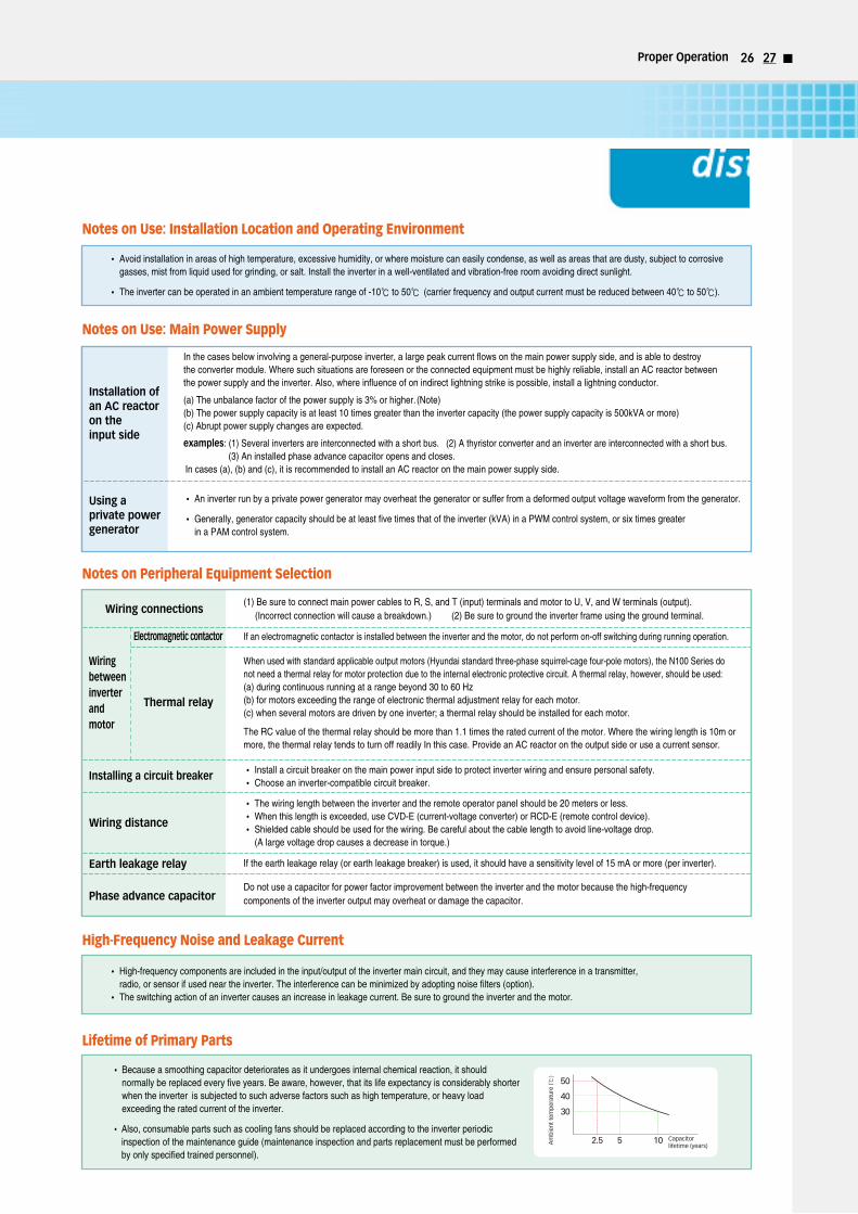
• Because a smoothing capacitor deteriorates as it undergoes internal chemical reaction, it shouldnormally be replaced every five years. Be aware, however, that its life expectancy is considerably shorterwhen the inverter is subjected to such adverse factors such as high temperature, or heavy loadexceeding the rated current of the inverter.
• Also, consumable parts such as cooling fans should be replaced according to the inverter periodicinspection of the maintenance guide (maintenance inspection and parts replacement must be performedby only specified trained personnel).
High-Frequency Noise and Leakage Current
Lifetime of Primary Parts

HH
IS-W
C-C
E-B
07-07, 2009.9 Designed by D
esign Korea
Head Office 1, Jeonha-dong, Dong-gu, Ulsan, Korea Tel: 82-52-202-8101~8 Fax: 82-52-202-8100
Seoul 140-2, Gye-dong, Jongno-gu, Seoul, Korea(Sales & Marketing) Tel. 82-2-746-7596, 8451 Fax. 82-2-746-8448
Orlando 3452 Lake Lynda Drive, Suite 170, Orlando, Florida 32817, U.S.A. Tel: 1-407-249-7350 Fax: 1-407-275-4940
New Jersey 300 Sylvan Avenue, Englewood Cliffs, NJ 07632, U.S.A. Tel: 1-201-816-0286 Fax: 1-201-816-4083
London 2nd Floor, The Triangle, 5-17 Hammersmith Grove, London, W6 0LG, UKTel: 44-20-8741-0501 Fax: 44-20-8741-5620
Tokyo 8th Fl., Yurakucho Denki Bldg.1-7-1, Yuraku-cho, Chiyoda-gu, Tokyo, 100-0006, JapanTel: 81-3-3212-2076, 3215-7159 Fax: 81-3-3211-2093
Osaka I-Room 5th Fl. Nagahori-Plaza Bldg. 2-4-8, Minami Senba, Chuo-Ku, Osaka, Japan, 542-0081Tel: 81-6-6261-5766, 5767 Fax: 81-6-6261-5818
Dubai Level 2, Unit 205, Emaar Square-Bldg.4 Sheikh Zayed Road, P.O.Box 252458, Dubai, U.A.E.Tel: 971-4-425-7995 Fax: 971-4-425-7996
Sofia 1271, Sofia 41, Rojen Blvd., BulgariaTel: 359-2-803-3200 Fax: 359-2-803-3203
Yangzhong No. 9 Xiandai Road, Xinba Scientific and Technologic Zone, Yangzhong, Jiangsu, P.R.C. Zip: 212212, ChinaTel: 86-511-8842-0666, 0212 Fax: 86-511-8842-0668, 0231