Embed Size (px)
DESCRIPTION
b
Citation preview

FLANGE MOUNT KITS FOR FRAMES MR4 TO MR7MOUNTING INSTRUCTIONS


DPD00962C 0
Document ID: DPD00962CRevision release date: 23.1.2013
GENERAL .....................................................................................................................................1FLANGE MOUNT - FRAMES MR4 - MR7 .....................................................................................2FLANGE MOUNT KIT FOR FRAME MR4 ......................................................................................7FLANGE MOUNT KIT FOR FRAME MR5 ....................................................................................12FLANGE MOUNT KIT FOR FRAME MR6 ....................................................................................17FLANGE MOUNT KIT FOR FRAME MR7 ....................................................................................23
1 DPD00962C
FLANGE MOUNT KITS FOR FRAMES MR4 TO MR7MOUNTING INSTRUCTIONS
GENERAL
Using the optional Flange Mounting Kit, you can mount your AC drive through the cabinet wall or similar surface so that the control unit of the drive remains inside the cabinet.
The correct installation of the Flange Mounting Kit might affect the IP protection class of the AC drive. If your drive is protected according to an IP54/Type12, or your drive is supplied with flange option at the factory, you only need to install the collars, as instructed. However, the power module of an IP21/Type1-protected drive will only become protected according to the IP54/Type12 on the rear side (see figure below), if all parts of the flange mounting kit are installed properly. The need for this has to be evaluated and these actions are explained in this guide.
Figure 1. Example of the flange mounting with MR9
9070.emf
Cabinett wall (or similar) Cabinett wall
or similar
Front
IP00
Rear IP54/Type 12

DPD00962C 2
FLANGE MOUNT - FRAMES MR4 - MR7
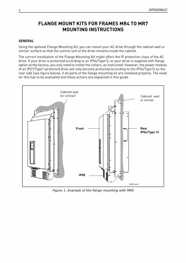
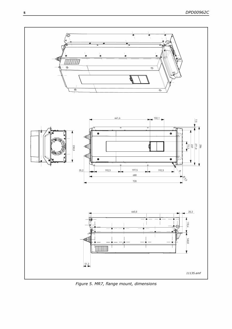
Figure 6. present the dimensions of the opening and the drive outline with the flange. Figures 2. - 5. present the dimensions of the drives with the flange mount option.
It is recommended that the embossed holes or self clinching nuts are used in the back plate for the drive mounting in order to guarantee the sealing.
Figure 2. MR4, flange mount, dimensions
11134.emf
152,0
15,0122,0
Ø 7,0
285 24
113357
341
101,6
72,1
18,5
32,8
39
77,0
190
134,0
128,0186,99

3 DPD00962C
Figure 3. MR5, flange mount, dimensions
11132.emf
Ø 7,0
Ø 7
436,0
454,1
262,5
145,0
144,0
150,0
169,0
9
13 382 24
39
33
27,5
100
214,0
114
11,5
72,2
145,0
101,9
12,0
DPD00962C 4
Figure 4. MR6, flange mount, dimensions
11133.emf
13,9
123,0
16,8 514,0
36,4
26,2
286,3 ± 20
229,0
106,0
Ø 7
2- Ø 4,0
115,5
196,012,0
18,0
6,0
184,0220,0
195,0201,0
Ø 7
101,9
566,0
580
232
72,2
355,6
5 DPD00962C
Figure 5. MR7, flange mount, dimensions
11135.emf
230,0
51,2
35,2
720
192,5 197,5
660,0
680
192,5
102,1441,6
20,3
237
271,0
286
7,5
72,3
8- Ø 5,5110,4
148,8
DPD00962C 6
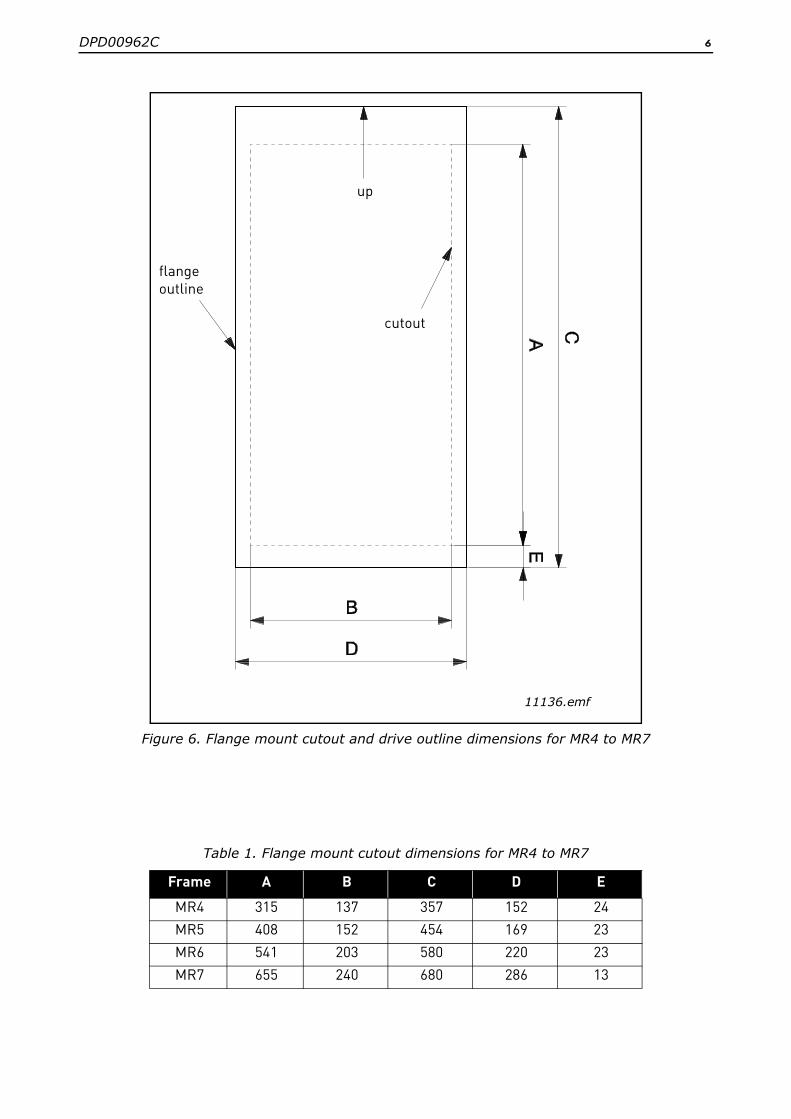
Figure 6. Flange mount cutout and drive outline dimensions for MR4 to MR7
Table 1. Flange mount cutout dimensions for MR4 to MR7
Frame A B C D E
MR4 315 137 357 152 24
MR5 408 152 454 169 23
MR6 541 203 580 220 23
MR7 655 240 680 286 13
11136.emf
up
flange
cutout
outline
7 DPD00962C
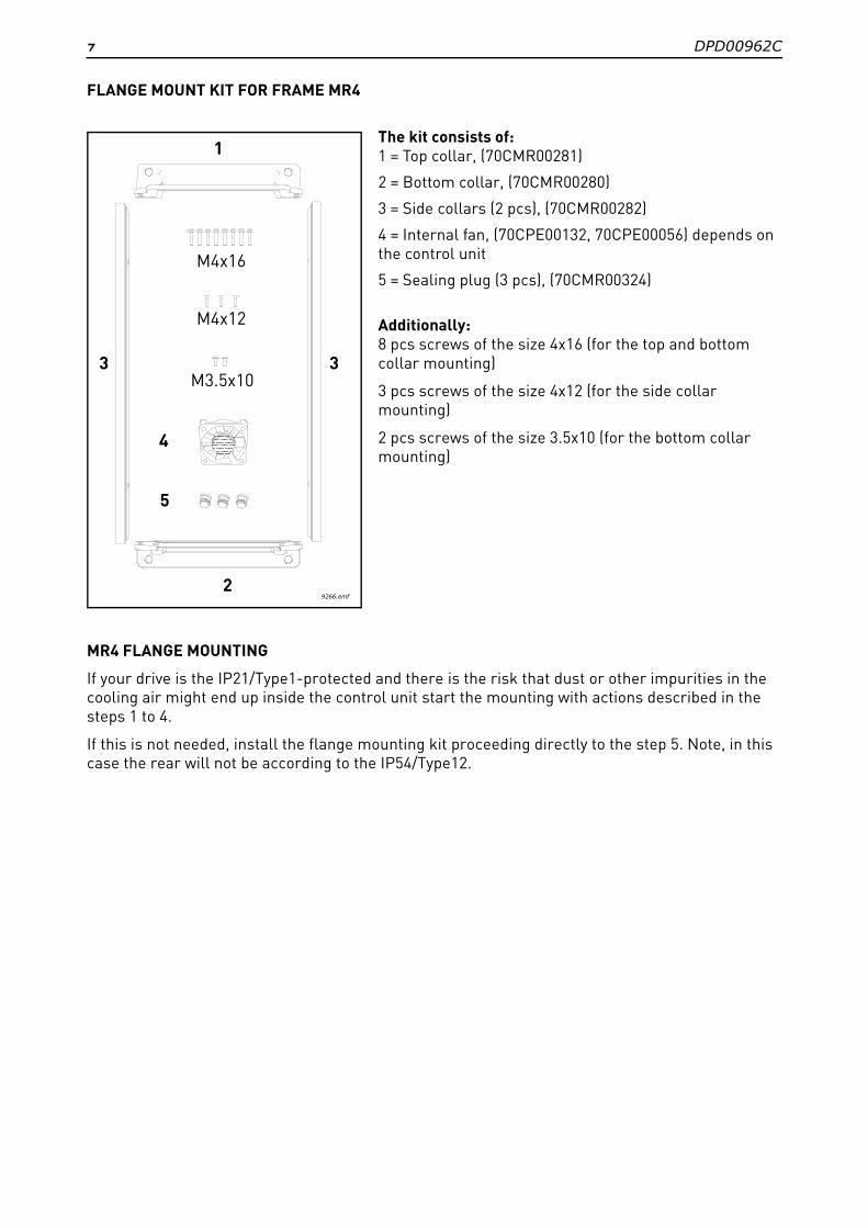
FLANGE MOUNT KIT FOR FRAME MR4
The kit consists of:1 = Top collar, (70CMR00281)
2 = Bottom collar, (70CMR00280)
3 = Side collars (2 pcs), (70CMR00282)
4 = Internal fan, (70CPE00132, 70CPE00056) depends on the control unit
5 = Sealing plug (3 pcs), (70CMR00324)
Additionally:8 pcs screws of the size 4x16 (for the top and bottom collar mounting)
3 pcs screws of the size 4x12 (for the side collar mounting)
2 pcs screws of the size 3.5x10 (for the bottom collar mounting)
MR4 FLANGE MOUNTING
If your drive is the IP21/Type1-protected and there is the risk that dust or other impurities in the cooling air might end up inside the control unit start the mounting with actions described in the steps 1 to 4.
If this is not needed, install the flange mounting kit proceeding directly to the step 5. Note, in this case the rear will not be according to the IP54/Type12.
9266.emf
M3.5x10
M4x12
M4x16
5
2
1
33
4

DPD00962C 8
1
Remove the cover of the drive.
Lift up the I/O protection plate.
The location of the internal fan depends on the control unit. If you have the control unit presented in the upper picture, Slide the internal fan into the opening with the label facing the cabling end of the drive.
If you have the control unit presented in the lower picture, install the internal fan with the label facing downwards.
11147.emf
11150.emf

9 DPD00962C
2
Connect the power wire to the power connector. The location of the power connector depends on the control unit.
3 Remove the main fan.
11148.emf
11149.emf
9289.emf
DPD00962C 10
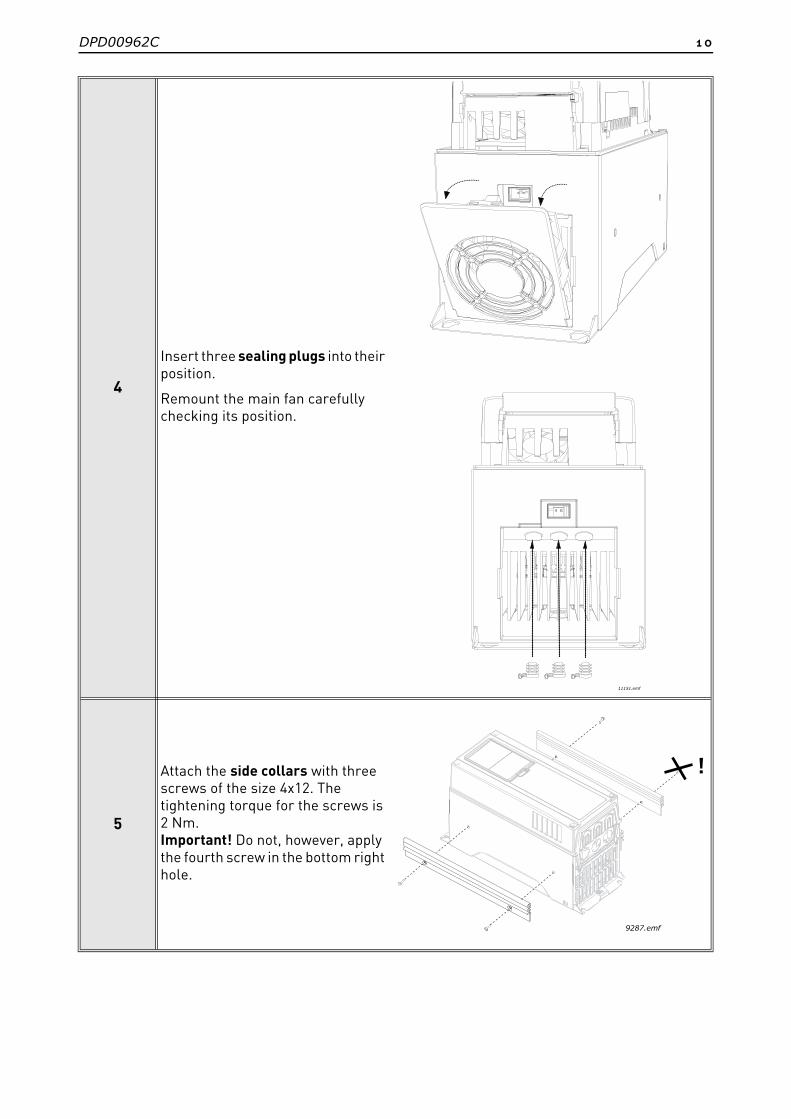
4
Insert three sealing plugs into their position.
Remount the main fan carefully checking its position.
5
Attach the side collars with three screws of the size 4x12. The tightening torque for the screws is 2 Nm.Important! Do not, however, apply the fourth screw in the bottom right hole.
11151.emf
!
9287.emf
11 DPD00962C
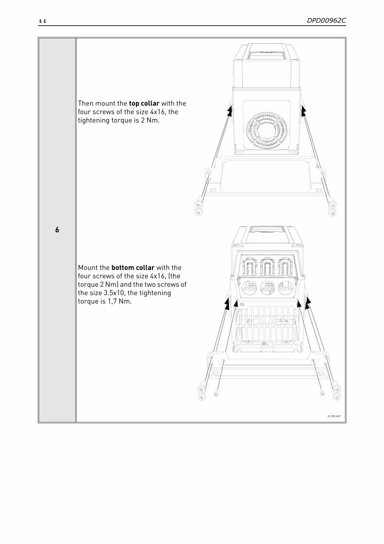
6
Then mount the top collar with the four screws of the size 4x16, the tightening torque is 2 Nm.
Mount the bottom collar with the four screws of the size 4x16, (the torque 2 Nm) and the two screws of the size 3.5x10, the tightening torque is 1,7 Nm.
11146.emf

DPD00962C 12
FLANGE MOUNT KIT FOR FRAME MR5
The kit consists of:1 = Top collar, (70CMR00176)
2 = Bottom collar, (70CMR00175)
3 = Side collars (2 pcs), (70CMR00090)
4 = Internal fan, (70CPE00056)
5 = Sealing plugs (4 pcs), (70CMR00324)
Additionally:8 pcs screws of the size 4x16 (for the top and bottom collar mounting)
4 pcs screws of the size 4x12 (for the side collar mounting)
2 pcs screws of the size 4x16 (for the mounting of the internal fan)
MR5 FLANGE MOUNTING
If your drive is the IP21/Type1-protected and there is the risk that dust or other impurities in the cooling air might end up inside the control unit start the mounting with actions described in the steps 1 to 4.
If this is not needed, install the flange mounting kit proceeding directly to the step 5. Note, in this case the rear will not be according to the IP54/Type12.
M4x16
M4x12
1
2
3 3
4
M4x10
5
9268.emf
13 DPD00962C
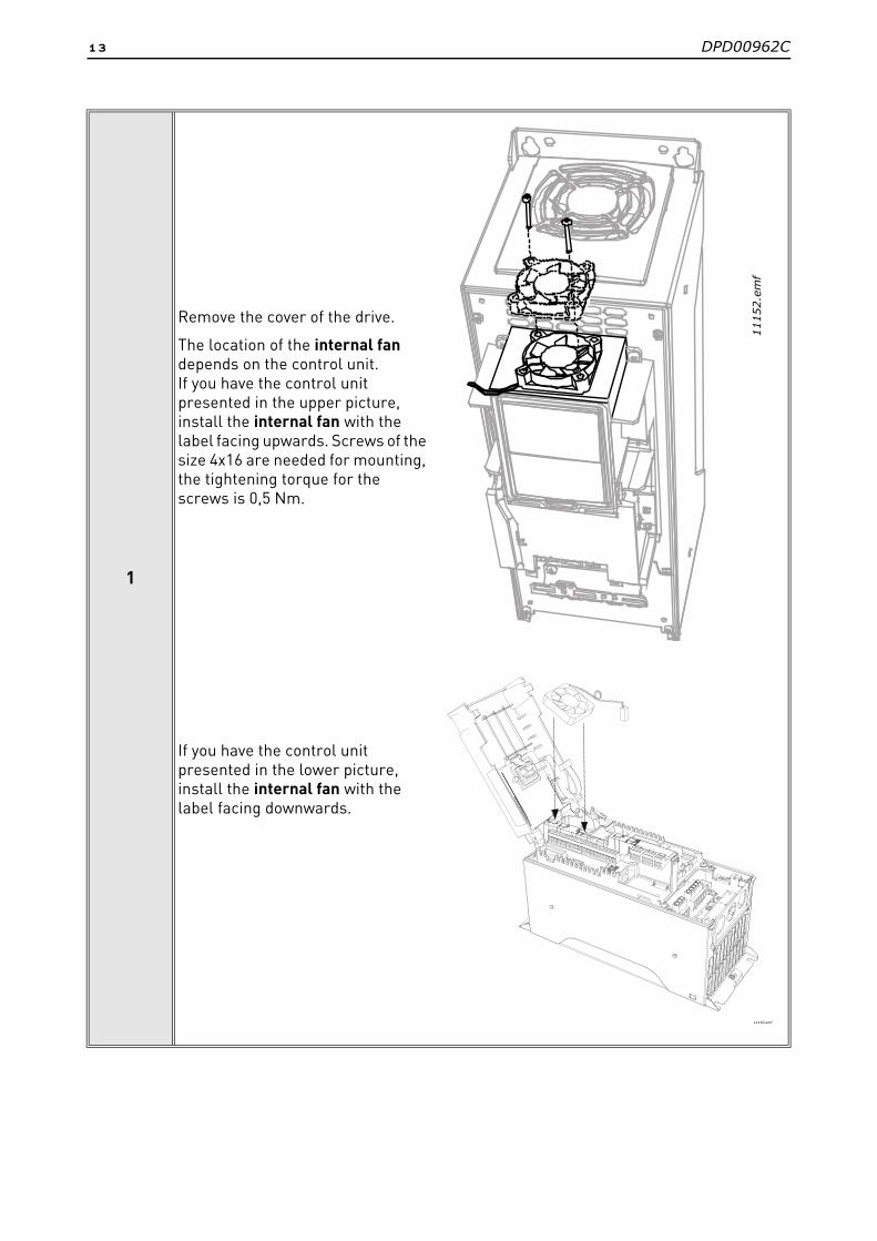
1
Remove the cover of the drive.
The location of the internal fan depends on the control unit. If you have the control unit presented in the upper picture, install the internal fan with the label facing upwards. Screws of the size 4x16 are needed for mounting, the tightening torque for the screws is 0,5 Nm.
If you have the control unit presented in the lower picture, install the internal fan with the label facing downwards.
1115
2.em
f
11150.emf
DPD00962C 14
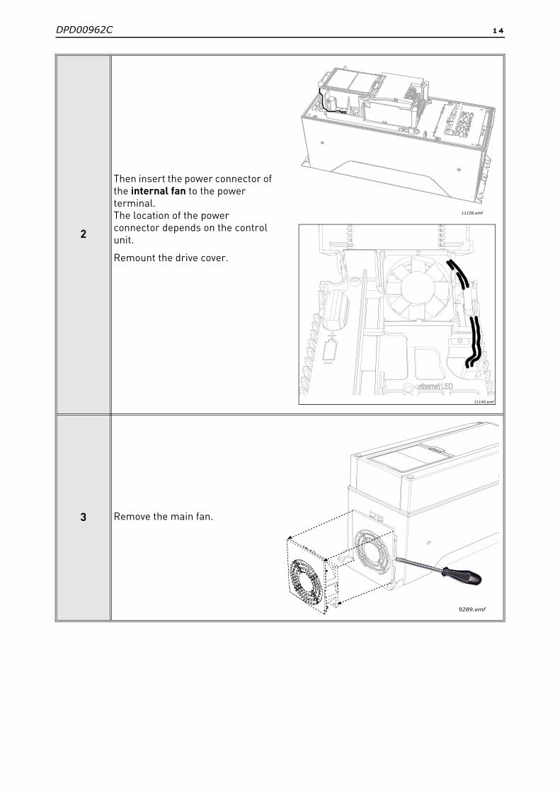
2
Then insert the power connector of the internal fan to the power terminal.The location of the power connector depends on the control unit.
Remount the drive cover.
3 Remove the main fan.
11156.emf
11149.emf
9289.emf

15 DPD00962C
4Insert the sealing plugs.
Remount the main fan.
5
Attach the side collars with the four screws of the size 4x12. The tightening torque for the screws is 2 Nm.
11145.emf
9269.emf
DPD00962C 16
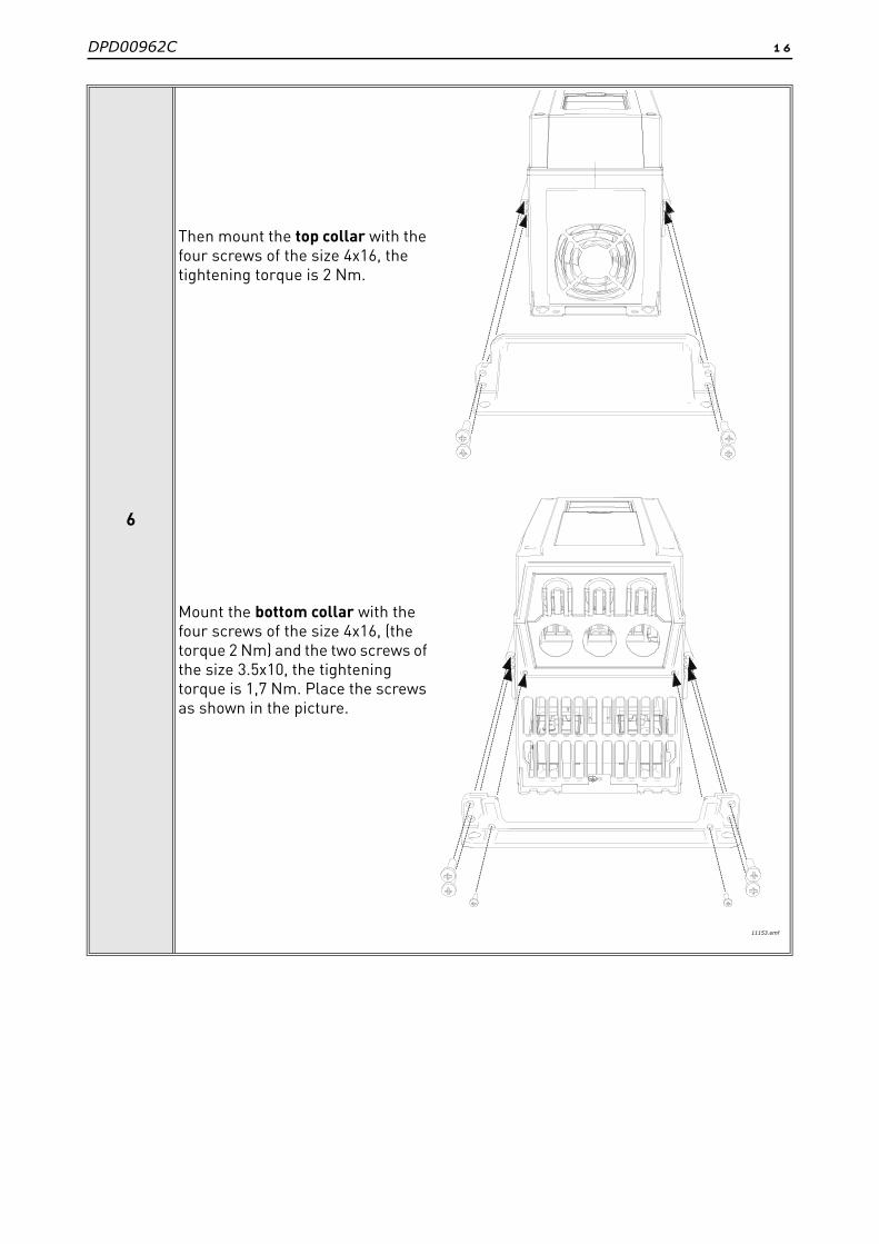
6
Then mount the top collar with the four screws of the size 4x16, the tightening torque is 2 Nm.
Mount the bottom collar with the four screws of the size 4x16, (the torque 2 Nm) and the two screws of the size 3.5x10, the tightening torque is 1,7 Nm. Place the screws as shown in the picture.
11153.emf
17 DPD00962C
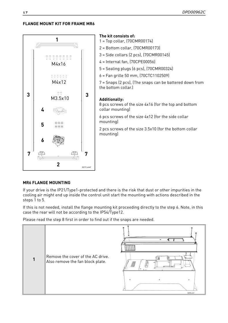
FLANGE MOUNT KIT FOR FRAME MR6
The kit consists of:1 = Top collar, (70CMR00174)
2 = Bottom collar, (70CMR00173)
3 = Side collars (2 pcs), (70CMR00145)
4 = Internal fan, (70CPE00056)
5 = Sealing plugs (6 pcs), (70CMR00324)
6 = Fan grille 50 mm, (70CTC1102509)
7 = Snaps (2 pcs), (The snaps can be battered down from the bottom collar.)
Additionally:8 pcs screws of the size 4x16 (for the top and bottom collar mounting)
6 pcs screws of the size 4x12 (for the side collar mounting)
2 pcs screws of the size 3.5x10 (for the bottom collar mounting)
MR6 FLANGE MOUNTING
If your drive is the IP21/Type1-protected and there is the risk that dust or other impurities in the cooling air might end up inside the control unit start the mounting with actions described in the steps 1 to 5.
If this is not needed, install the flange mounting kit proceeding directly to the step 6. Note, in this case the rear will not be according to the IP54/Type12.
Please read the step 8 first in order to find out if the snaps are needed.
1Remove the cover of the AC drive. Also remove the fan block plate.
M4x16
M4x12
1
2
3 3
7 7
M3.5x10
4
5
9271.emf
6
9296.emf
DPD00962C 18
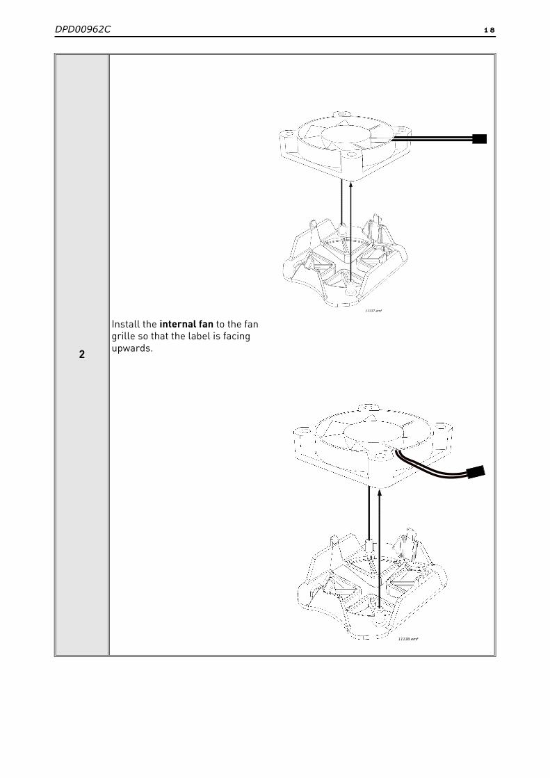
2
Install the internal fan to the fan grille so that the label is facing upwards.
11137.emf
11137.emf
11137.emf
11138.emf
19 DPD00962C
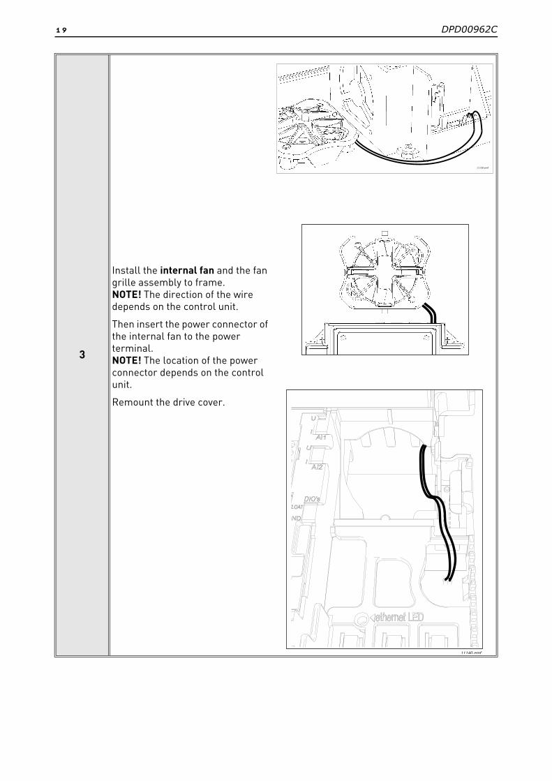
3
Install the internal fan and the fan grille assembly to frame. NOTE! The direction of the wire depends on the control unit.
Then insert the power connector of the internal fan to the power terminal. NOTE! The location of the power connector depends on the control unit.
Remount the drive cover.
11140.emf
11139.emf
DPD00962C 20
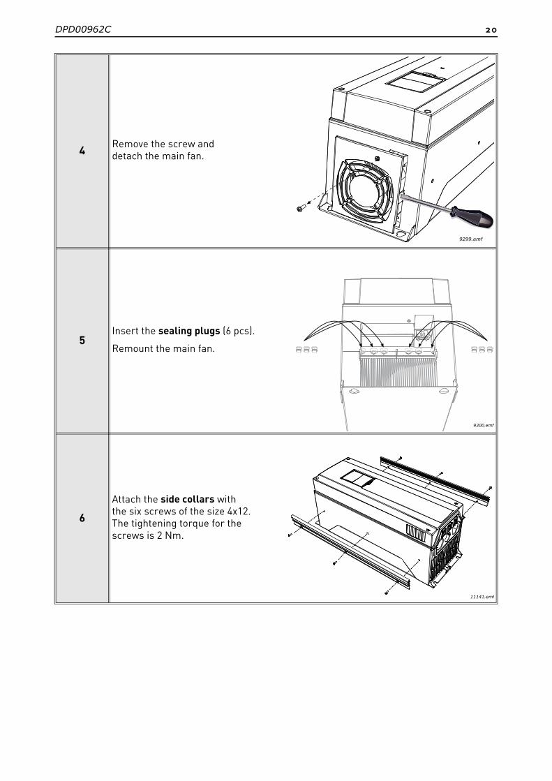
4Remove the screw and detach the main fan.
5Insert the sealing plugs (6 pcs).
Remount the main fan.
6
Attach the side collars with the six screws of the size 4x12. The tightening torque for the screws is 2 Nm.
9299.emf
9300.emf
11141.emf
21 DPD00962C
7
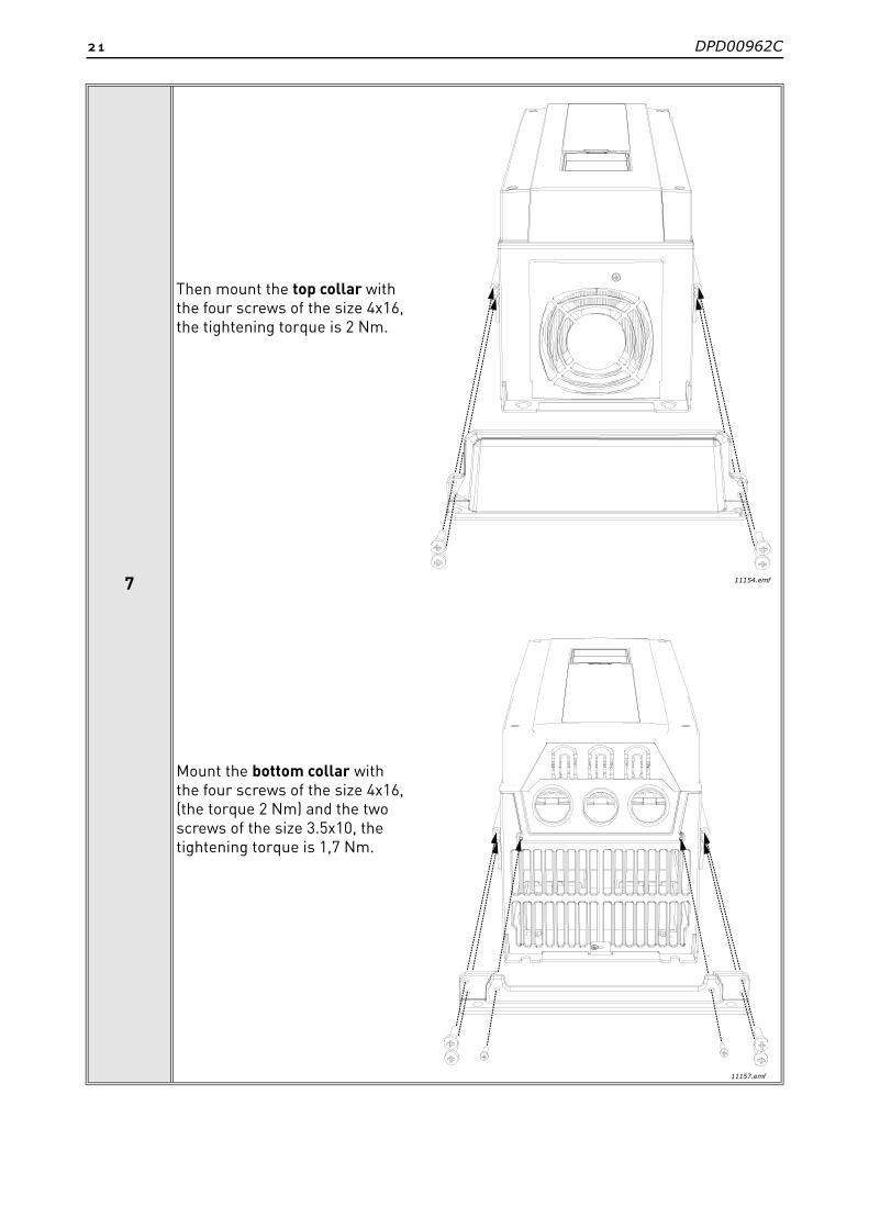
Then mount the top collar with the four screws of the size 4x16, the tightening torque is 2 Nm.
Mount the bottom collar with the four screws of the size 4x16, (the torque 2 Nm) and the two screws of the size 3.5x10, the tightening torque is 1,7 Nm.
11154.emf
11157.emf
DPD00962C 22
8
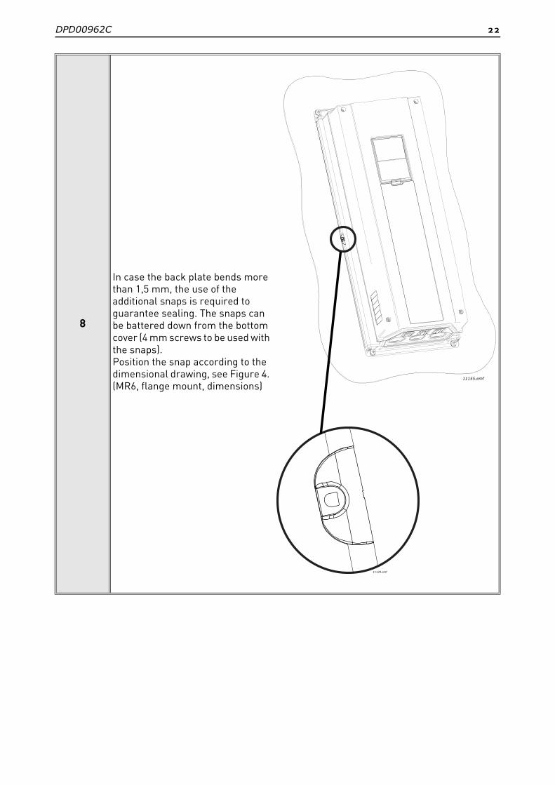
In case the back plate bends more than 1,5 mm, the use of the additional snaps is required to guarantee sealing. The snaps can be battered down from the bottom cover (4 mm screws to be used with the snaps). Position the snap according to the dimensional drawing, see Figure 4. (MR6, flange mount, dimensions)
11155.emf
11129.emf
23 DPD00962C
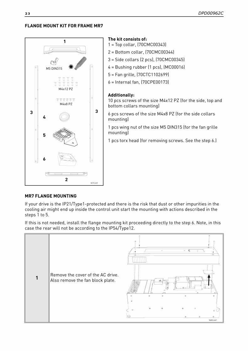
FLANGE MOUNT KIT FOR FRAME MR7
The kit consists of:1 = Top collar, (70CMC00343)
2 = Bottom collar, (70CMC00344)
3 = Side collars (2 pcs), (70CMC00345)
4 = Bushing rubber (1 pcs), (MC00016)
5 = Fan grille, (70CTC1102699)
6 = Internal fan, (70CPE00173)
Additionally:10 pcs screws of the size M4x12 PZ (for the side, top and bottom collars mounting)
6 pcs screws of the size M4x8 PZ (for the side collars mounting)
1 pcs wing nut of the size M5 DIN315 (for the fan grille mounting)
1 pcs torx head (for removing screws. See the step 6.)
MR7 FLANGE MOUNTING
If your drive is the IP21/Type1-protected and there is the risk that dust or other impurities in the cooling air might end up inside the control unit start the mounting with actions described in the steps 1 to 5.
If this is not needed, install the flange mounting kit proceeding directly to the step 6. Note, in this case the rear will not be according to the IP54/Type12.
1Remove the cover of the AC drive. Also remove the fan block plate.
9274.emf
4
6
5
3 3
2
M4x12 PZ
M4x8 PZ
1
M5 DIN315
9283.emf

DPD00962C 24
2Place the bushing rubber into its position.
3
Install the internal fan so that the wire leaves to right direction. The direction depends on the control unit. See the step 4 below.
9284
.em
f92
85.e
mf
25 DPD00962C
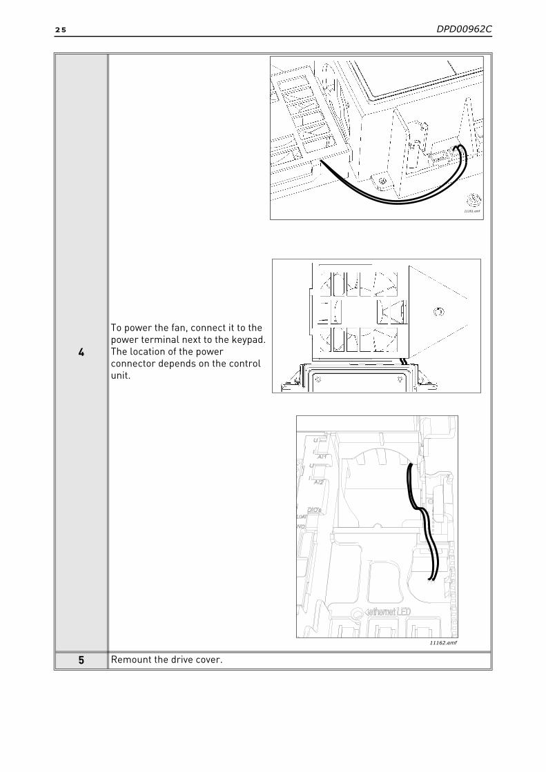
4
To power the fan, connect it to the power terminal next to the keypad.The location of the power connector depends on the control unit.
5 Remount the drive cover.
11162.emf
11161.emf

DPD00962C 26
6
Remove the screws as shown in the picture from both sides of the drive.Use the torx head provided with the kit.
7
Remove the screws as shown in the picture from the top and bottom of the drive. Use the torx head provided with the kit.
9275.emf
9276.emf
9277.emf

27 DPD00962C
8
Fix the side collars with the screws starting from the top: 6 pcs M4x12 PZ screws for the upper three holes and 6 pcs M4x8 PZ for the lower three holes. The tightening torque for the screws is 2 Nm.
9Fix the top collar with the two M4x12 PZ screws. The tightening torque for the screws is 2 Nm.
M4x12 PZM4x8 PZ
9278
.em
f
9279.emf
DPD00962C 28
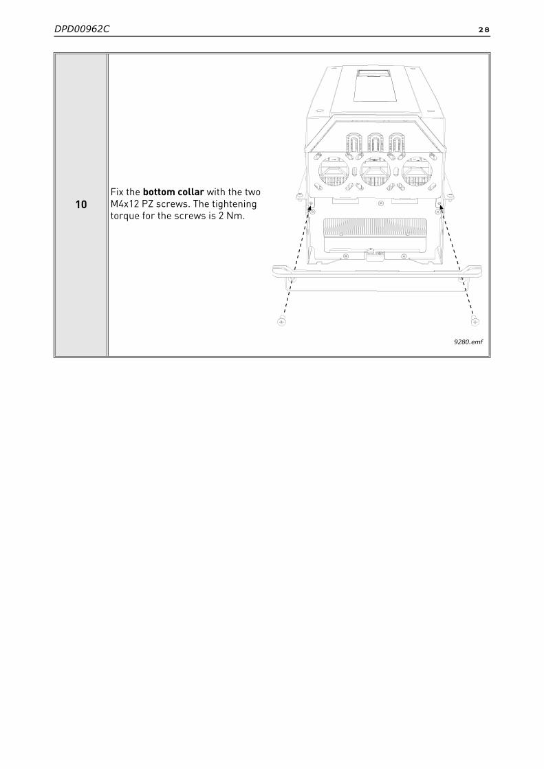
10Fix the bottom collar with the two M4x12 PZ screws. The tightening torque for the screws is 2 Nm.
9280.emf