Embed Size (px)
DESCRIPTION
vacon
Citation preview
nx
ethe
user’s manual
frequency converters
rnet option board
opt-ci
2 • vacon Introduction
Tel. +358 (0)201 2121 • Fax +358 (0)201 212 205
INDEX
1. Introduction ....................................................................................................................... 3 2. Ethernet board technical data............................................................................................ 4
2.1 Overview...................................................................................................................................... 4 2.2 OPTCI card .................................................................................................................................. 4 2.3 Ethernet, introduction ................................................................................................................ 5 2.4 Ethernet ...................................................................................................................................... 5 2.5 Connections and Wiring.............................................................................................................. 7
3. Installation ......................................................................................................................... 8 3.1 Installing the Ethernet Option Board in a Vacon NX Unit.......................................................... 8 3.2 IP Tool NCIPConfig ................................................................................................................... 10
4. Modbus/TCP..................................................................................................................... 13 4.1 MODBUS/TCP vs. MODBUS RTU.............................................................................................. 14 4.2 Ethernet Option Board's Modbus Addresses........................................................................... 14 4.3 Coil (0x01) Register................................................................................................................... 14 4.4 Input Discrete (1x)..................................................................................................................... 16 4.5 Holding Registers (400001 - 410633) ....................................................................................... 18 4.6 Input Registers (3x)................................................................................................................... 22
5. Start-up Test.................................................................................................................... 24 5.1 Frequency Converter Settings............................................................................................... 24 5.2 Master Unit Programming ..................................................................................................... 24
6. Error Codes and Errors.................................................................................................... 25 6.1 Frequency Converter Error Codes........................................................................................... 25 6.2 Modbus TCP .............................................................................................................................. 25
7. Appendix .......................................................................................................................... 26
Introduction vacon • 3
24-hour support +358 (0)40 837 1150 • Email: [email protected]
1
1. INTRODUCTION
Vacon NX frequency converters can be connected to Ethernet using an Ethernet fieldbus board OPT-CI. The OPT-CI can be installed in the card slots D or E. Every appliance connected to an Ethernet network has two identifiers; a MAC address and an IP address. The MAC address (Address format: xx:xx:xx:xx:xx:xx ) is unique to the appliance and cannot be changed. The Ethernet board's MAC address can be found on the sticker attached to the board or by using the Vacon IP tool software NCIPConfig. Please find the software installation at www.vacon.com In a local network, IP addresses can be defined by the user as long as all units connected to the network are given the same network portion of the address. For more information about IP addresses, contact your Network Administrator. Overlapping IP addresses cause conflicts between appliances. For more information about setting IP addresses, see Section 3, Installation.
WARNING!
Internal components and circuit boards are at high potential when the frequency converter is connected to the power source. This voltage is extremely dangerous and may cause death or severe injury if you come into contact with it.
4 • vacon Ethernet board technical data
Tel. +358 (0)201 2121 • Fax +358 (0)201 212 205
2
2. ETHERNET BOARD TECHNICAL DATA
2.1 Overview
General Card Name OPT-CI Ethernet connections
Interface RJ-45 connector
Transfer cable Foiled CAT5e Speed 10 / 100 Mb Duplex half / full
Communications
Default IP-address 192.168.0.10 Protocols Modbus / TCP
Ambient operating temperature
–10°C…50°C
Storing temperature
–40°C…70°C
Humidity <95%, no condensation allowed Altitude Max. 1000 m
Environment
Vibration 0.5 G at 9…200 Hz Safety Fulfils EN50178 standard
Table 2-1. Ethernet board technical data
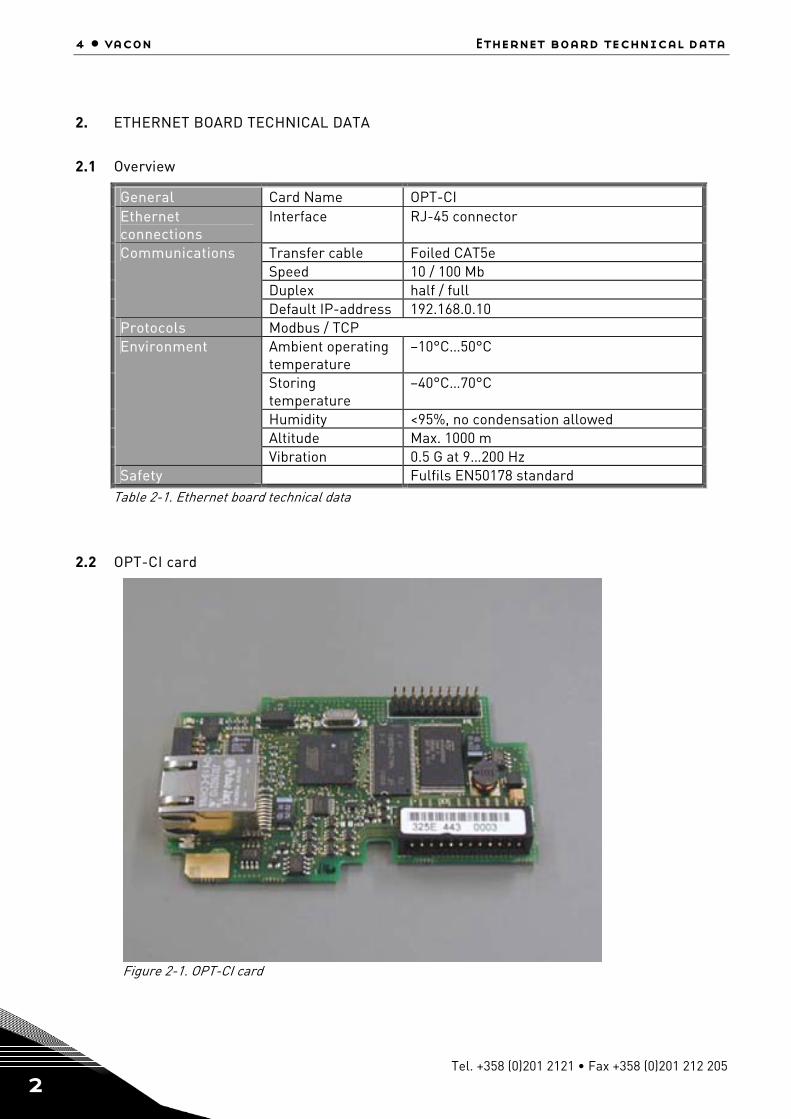
2.2 OPT-CI card
Figure 2-1. OPT-CI card
Ethernet board technical data vacon • 5
24-hour support +358 (0)40 837 1150 • Email: [email protected]
2
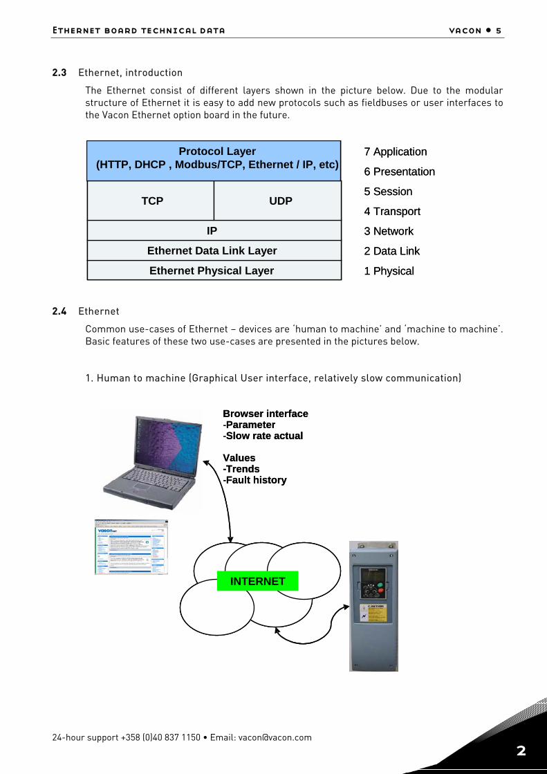
2.3 Ethernet, introduction
The Ethernet consist of different layers shown in the picture below. Due to the modular structure of Ethernet it is easy to add new protocols such as fieldbuses or user interfaces to the Vacon Ethernet option board in the future.
2.4 Ethernet
Common use-cases of Ethernet – devices are ‘human to machine’ and ‘machine to machine’. Basic features of these two use-cases are presented in the pictures below. 1. Human to machine (Graphical User interface, relatively slow communication)
1 Physical
2 Data Link
3 Network
4 Transport
5 Session
6 Presentation
7 Application
Ethernet Physical Layer
Ethernet Data Link Layer
IP
TCP UDP
Protocol Layer(HTTP, DHCP , Modbus/TCP, Ethernet / IP, etc)
1 Physical
2 Data Link
3 Network
4 Transport
5 Session
6 Presentation
7 Application
Ethernet Physical Layer
Ethernet Data Link Layer
IP
TCP UDP
Protocol Layer(HTTP, DHCP , Modbus/TCP, Ethernet / IP, etc)
Ethernet Physical Layer
Ethernet Data Link Layer
IP
TCP UDP
Protocol Layer(HTTP, DHCP , Modbus/TCP, Ethernet / IP, etc)
INTERNET
Browser interface-Parameter-Slow rate actual
Values-Trends-Fault history
INTERNETINTERNET
Browser interface-Parameter-Slow rate actual
Values-Trends-Fault history
6 • vacon Ethernet board technical data
Tel. +358 (0)201 2121 • Fax +358 (0)201 212 205
2
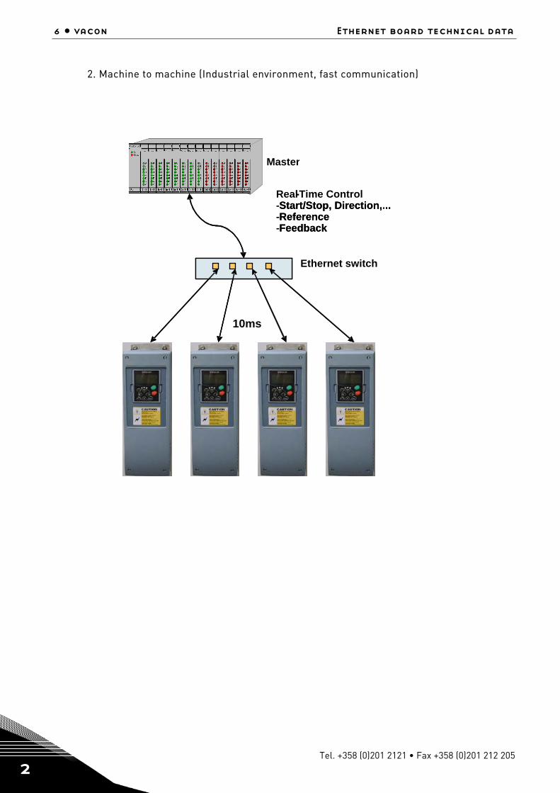
2. Machine to machine (Industrial environment, fast communication)
PLC or Programmable Controller
Real-Time Control-Start/Stop, Direction,...-Reference-Feedback
PLC or Programmable ControllerPLC or Programmable Controller
10ms
-
Master
-Start/Stop, Direction, ..-Reference-Feedback
Ethernet switch

Ethernet board technical data vacon • 7
24-hour support +358 (0)40 837 1150 • Email: [email protected]
2
2.5 Connections and Wiring
The Ethernet board supports 10/100Mb speeds in both Full and Half-duplex modes. The boards must be connected to the Ethernet network with a shielded CAT-5e cable. Use a so-called crossover cable if you want to connect the Ethernet option board directly to the master appliance. Use only industrial standard components in the network and avoid complex structures to minimize the length of response time and the amount of incorrect dispatches.
8 • vacon installation
Tel. +358 (0)201 2121 • Fax +358 (0)201 212 205
3
3. INSTALLATION
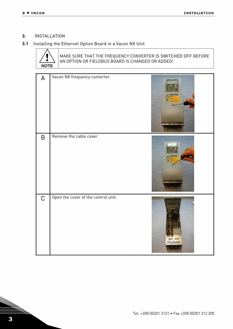
3.1 Installing the Ethernet Option Board in a Vacon NX Unit
!NOTE
MAKE SURE THAT THE FREQUENCY CONVERTER IS SWITCHED OFF BEFORE AN OPTION OR FIELDBUS BOARD IS CHANGED OR ADDED!
A Vacon NX frequency converter.
B Remove the cable cover.
C Open the cover of the control unit.
Installation vacon • 9
24-hour support +358 (0)40 837 1150 • Email: [email protected]
3
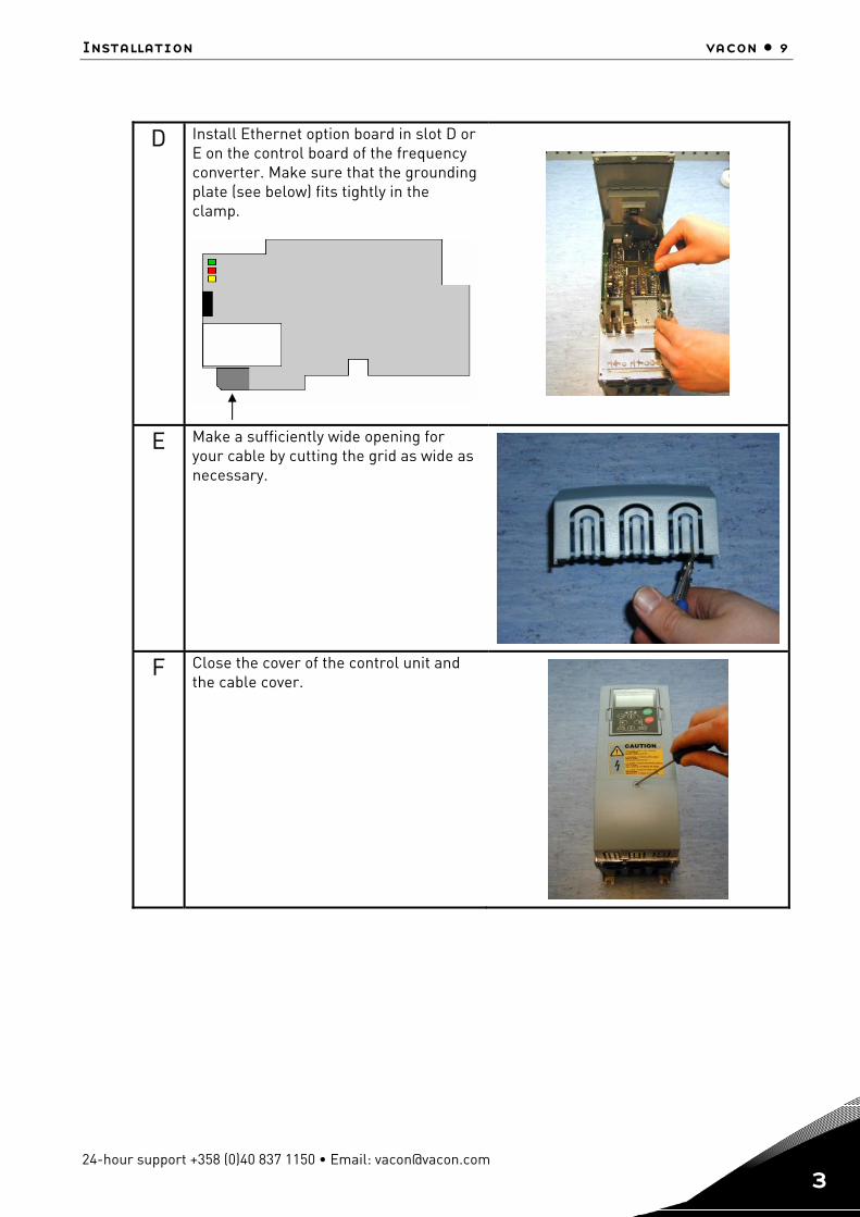
D Install Ethernet option board in slot D or E on the control board of the frequency converter. Make sure that the grounding plate (see below) fits tightly in the clamp.
E Make a sufficiently wide opening for your cable by cutting the grid as wide as necessary.
F Close the cover of the control unit and the cable cover.
10 • vacon installation
Tel. +358 (0)201 2121 • Fax +358 (0)201 212 205
3
3.2 IP Tool NCIPConfig
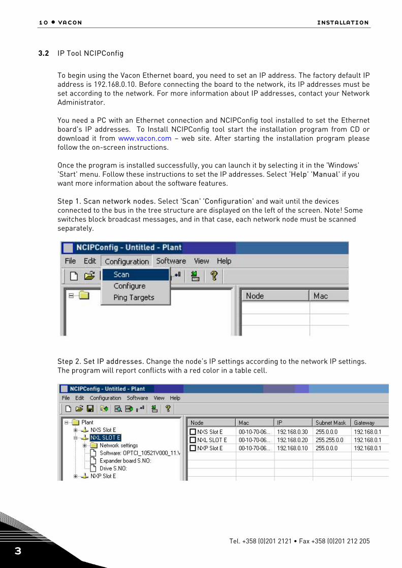
To begin using the Vacon Ethernet board, you need to set an IP address. The factory default IP address is 192.168.0.10. Before connecting the board to the network, its IP addresses must be set according to the network. For more information about IP addresses, contact your Network Administrator. You need a PC with an Ethernet connection and NCIPConfig tool installed to set the Ethernet board's IP addresses. To Install NCIPConfig tool start the installation program from CD or download it from www.vacon.com – web site. After starting the installation program please follow the on-screen instructions.
Once the program is installed successfully, you can launch it by selecting it in the 'Windows' 'Start' menu. Follow these instructions to set the IP addresses. Select 'Help' 'Manual' if you want more information about the software features. Step 1. Scan network nodes. Select 'Scan' 'Configuration' and wait until the devices connected to the bus in the tree structure are displayed on the left of the screen. Note! Some switches block broadcast messages, and in that case, each network node must be scanned separately.
Step 2. Set IP addresses. Change the node’s IP settings according to the network IP settings. The program will report conflicts with a red color in a table cell.
Installation vacon • 11
24-hour support +358 (0)40 837 1150 • Email: [email protected]
3
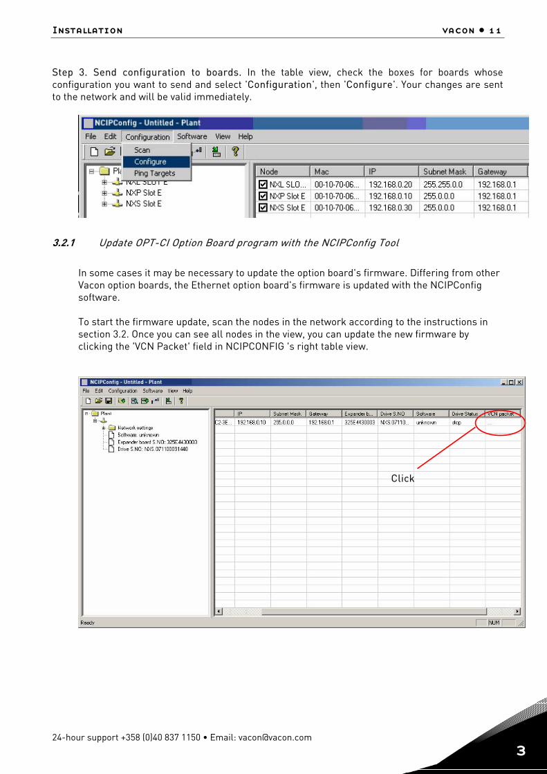
Step 3. Send configuration to boards. In the table view, check the boxes for boards whose configuration you want to send and select 'Configuration', then 'Configure'. Your changes are sent to the network and will be valid immediately.
3.2.1 Update OPT-CI Option Board program with the NCIPConfig Tool
In some cases it may be necessary to update the option board's firmware. Differing from other Vacon option boards, the Ethernet option board's firmware is updated with the NCIPConfig software. To start the firmware update, scan the nodes in the network according to the instructions in section 3.2. Once you can see all nodes in the view, you can update the new firmware by clicking the 'VCN Packet' field in NCIPCONFIG 's right table view.
Click
12 • vacon installation
Tel. +358 (0)201 2121 • Fax +358 (0)201 212 205
3
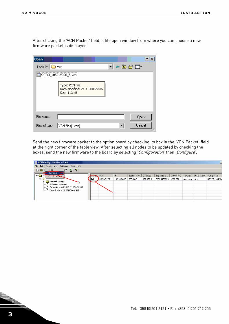
After clicking the 'VCN Packet' field, a file open window from where you can choose a new firmware packet is displayed.
Send the new firmware packet to the option board by checking its box in the 'VCN Packet' field at the right corner of the table view. After selecting all nodes to be updated by checking the boxes, send the new firmware to the board by selecting 'Configuration' then 'Configure'.
2
1
Modbus/tcp vacon • 13
24-hour support +358 (0)40 837 1150 • Email: [email protected]
4
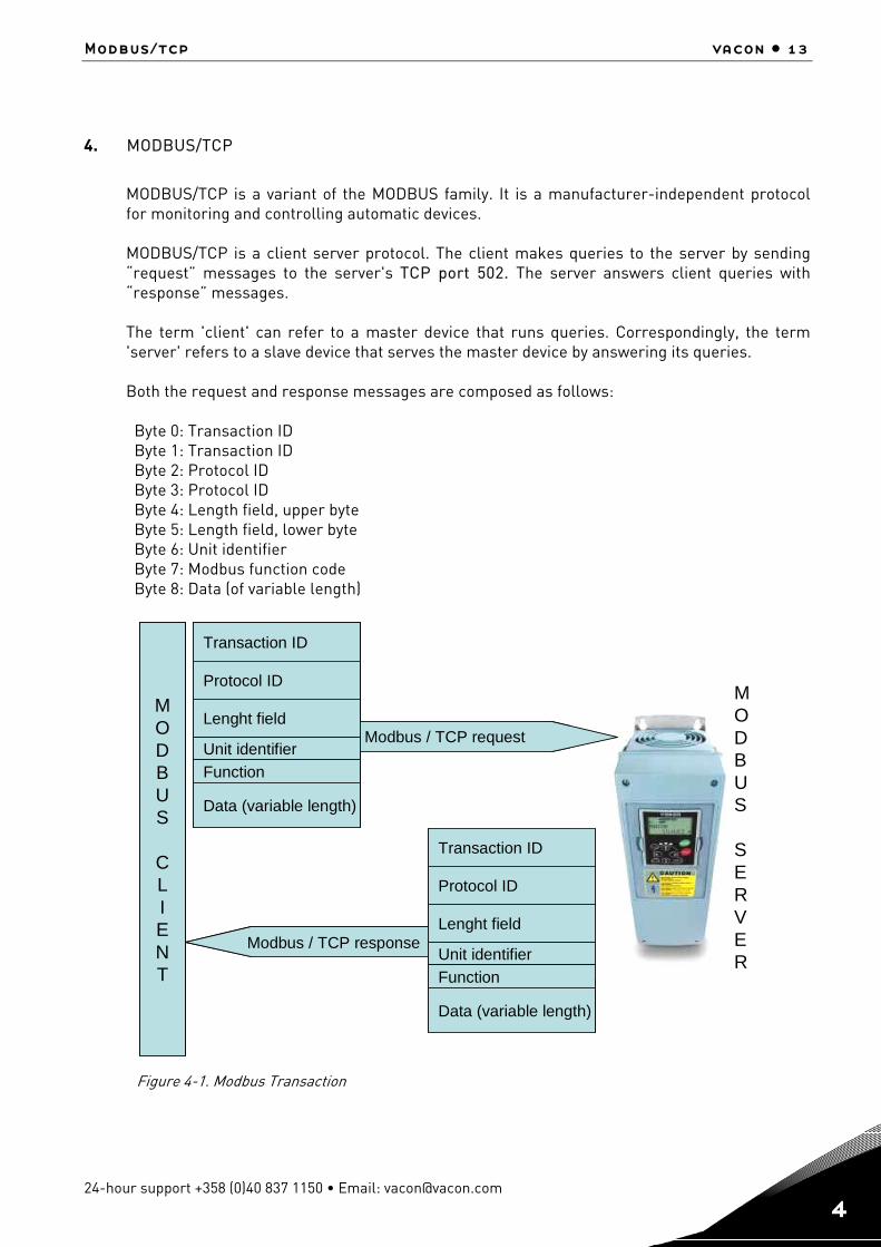
4. MODBUS/TCP
MODBUS/TCP is a variant of the MODBUS family. It is a manufacturer-independent protocol for monitoring and controlling automatic devices. MODBUS/TCP is a client server protocol. The client makes queries to the server by sending “request” messages to the server's TCP port 502. The server answers client queries with “response” messages. The term 'client' can refer to a master device that runs queries. Correspondingly, the term 'server' refers to a slave device that serves the master device by answering its queries. Both the request and response messages are composed as follows: Byte 0: Transaction ID Byte 1: Transaction ID Byte 2: Protocol ID Byte 3: Protocol ID Byte 4: Length field, upper byte Byte 5: Length field, lower byte Byte 6: Unit identifier Byte 7: Modbus function code Byte 8: Data (of variable length)
Figure 4-1. Modbus Transaction
Modbus / TCP request
MODBUS
CLIENT
Transaction ID
Protocol ID
Unit identifier
Lenght field
Function
Data (variable length)
Modbus / TCP response
Transaction ID
Protocol ID
Unit identifier
Lenght field
Function
Data (variable length)
MODBUS
SERVER
Modbus / TCP request
MODBUS
CLIENT
Transaction ID
Protocol ID
Unit identifier
Lenght field
Function
Data (variable length)
Modbus / TCP response
Transaction ID
Protocol ID
Unit identifier
Lenght field
Function
Data (variable length)
MODBUS
SERVER
14 • vacon Modbus/TCP
Tel. +358 (0)201 2121 • Fax +358 (0)201 212 205
4
4.1 MODBUS/TCP vs. MODBUS RTU
Compared to the MODBUS RTU protocol, the MODBUS/TCP differs mostly in error checking and slave addresses. As the TCP already includes an efficient error checking function, the MODBUS/TCP protocol does not include a separate CRC field. In addition to the error checking functionality, the TCP is responsible for resending packets and for splitting long messages so that they fit the TCP frames. The slave address field of the MODBUS/RTU is named as the unit identifier field in MODBUS/TCP, and it is only used when one IP address stands for several endpoints.
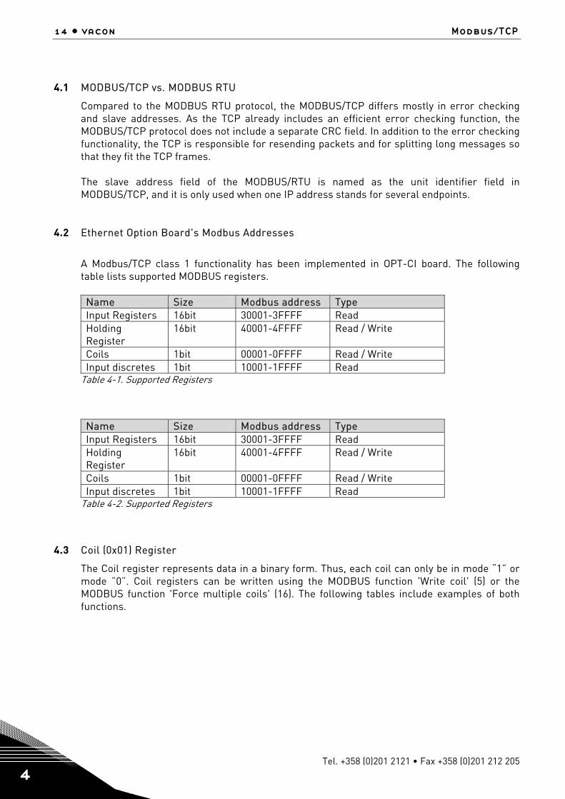
4.2 Ethernet Option Board's Modbus Addresses
A Modbus/TCP class 1 functionality has been implemented in OPT-CI board. The following table lists supported MODBUS registers.
Name Size Modbus address Type Input Registers 16bit 30001-3FFFF Read Holding Register
16bit 40001-4FFFF Read / Write
Coils 1bit 00001-0FFFF Read / Write Input discretes 1bit 10001-1FFFF Read
Table 4-1. Supported Registers
Name Size Modbus address Type Input Registers 16bit 30001-3FFFF Read Holding Register
16bit 40001-4FFFF Read / Write
Coils 1bit 00001-0FFFF Read / Write Input discretes 1bit 10001-1FFFF Read
Table 4-2. Supported Registers
4.3 Coil (0x01) Register
The Coil register represents data in a binary form. Thus, each coil can only be in mode “1” or mode ”0”. Coil registers can be written using the MODBUS function 'Write coil' (5) or the MODBUS function 'Force multiple coils' (16). The following tables include examples of both functions.
Modbus/tcp vacon • 15
24-hour support +358 (0)40 837 1150 • Email: [email protected]
4
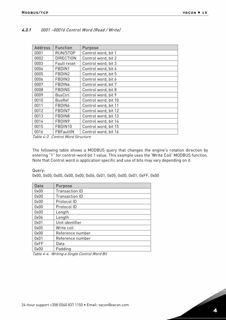
4.3.1 0001 –00016 Control Word (Read / Write)
Address Function Purpose 0001 RUN/STOP Control word, bit 1 0002 DIRECTION Control word, bit 2 0003 Fault reset Control word, bit 3 0004 FBDIN1 Control word, bit 4 0005 FBDIN2 Control word, bit 5 0006 FBDIN3 Control word, bit 6 0007 FBDIN4 Control word, bit 7 0008 FBDIN5 Control word, bit 8 0009 BusCtrl Control word, bit 9 0010 BusRef Control word, bit 10 0011 FBDIN6 Control word, bit 11 0012 FBDIN7 Control word, bit 12 0013 FBDIN8 Control word, bit 13 0014 FBDIN9 Control word, bit 14 0015 FBDIN10 Control word, bit 15 0016 FBFaultIN Control word, bit 16
Table 4-3. Control Word Structure
The following table shows a MODBUS query that changes the engine's rotation direction by entering “1” for control-word bit 1 value. This example uses the 'Write Coil' MODBUS function. Note that Control word is application specific and use of bits may vary depending on it. Query: 0x00, 0x00, 0x00, 0x00, 0x00, 0x06, 0x01, 0x05, 0x00, 0x01, 0xFF, 0x00 Data Purpose 0x00 Transaction ID 0x00 Transaction ID 0x00 Protocol ID 0x00 Protocol ID 0x00 Length 0x06 Length 0x01 Unit identifier 0x05 Write coil 0x00 Reference number 0x01 Reference number 0xFF Data 0x00 Padding
Table 4-4. Writing a Single Control Word Bit
16 • vacon Modbus/TCP
Tel. +358 (0)201 2121 • Fax +358 (0)201 212 205
4
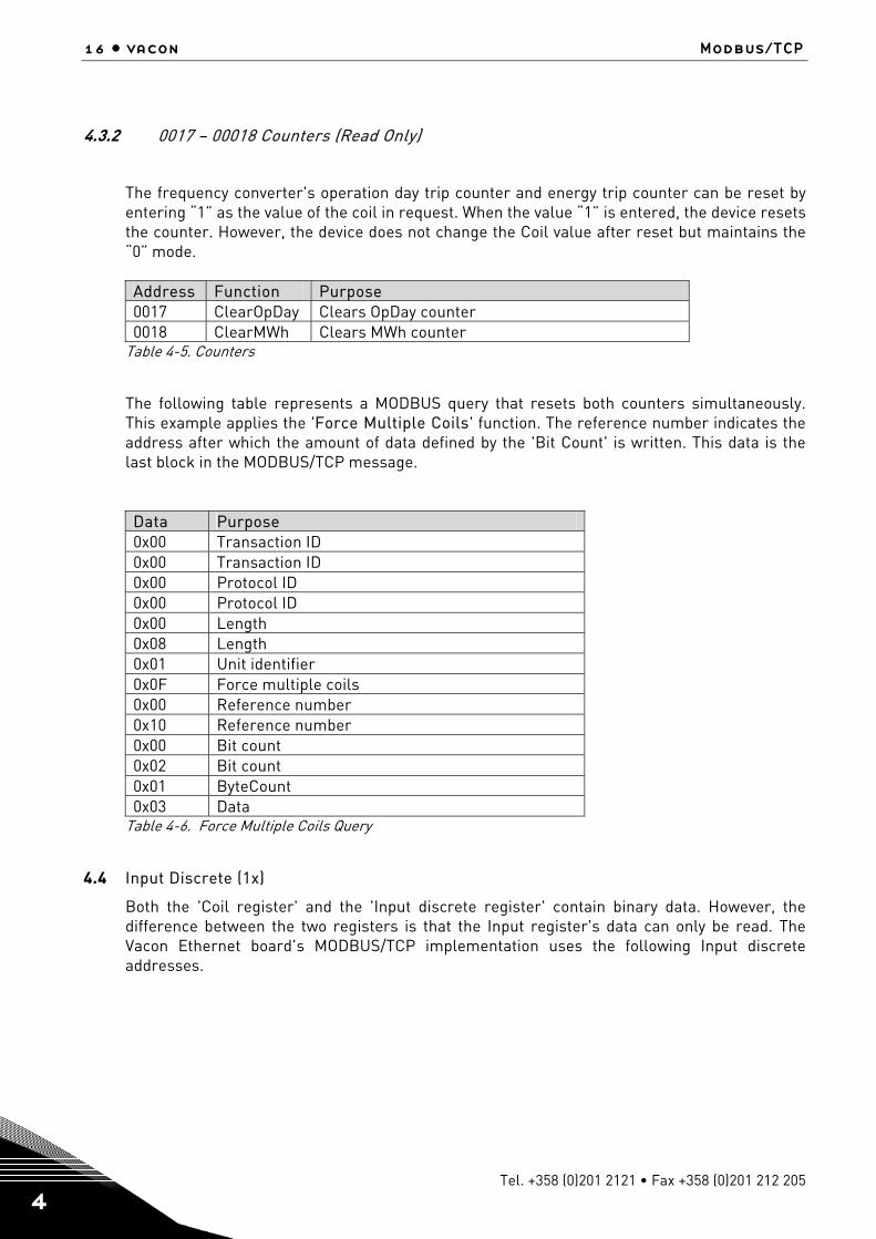
4.3.2 0017 – 00018 Counters (Read Only)
The frequency converter's operation day trip counter and energy trip counter can be reset by entering “1” as the value of the coil in request. When the value “1” is entered, the device resets the counter. However, the device does not change the Coil value after reset but maintains the “0” mode. Address Function Purpose 0017 ClearOpDay Clears OpDay counter 0018 ClearMWh Clears MWh counter
Table 4-5. Counters
The following table represents a MODBUS query that resets both counters simultaneously. This example applies the 'Force Multiple Coils' function. The reference number indicates the address after which the amount of data defined by the 'Bit Count' is written. This data is the last block in the MODBUS/TCP message. Data Purpose 0x00 Transaction ID 0x00 Transaction ID 0x00 Protocol ID 0x00 Protocol ID 0x00 Length 0x08 Length 0x01 Unit identifier 0x0F Force multiple coils 0x00 Reference number 0x10 Reference number 0x00 Bit count 0x02 Bit count 0x01 ByteCount 0x03 Data
Table 4-6. Force Multiple Coils Query
4.4 Input Discrete (1x)
Both the 'Coil register' and the 'Input discrete register' contain binary data. However, the difference between the two registers is that the Input register's data can only be read. The Vacon Ethernet board's MODBUS/TCP implementation uses the following Input discrete addresses.
Modbus/tcp vacon • 17
24-hour support +358 (0)40 837 1150 • Email: [email protected]
4
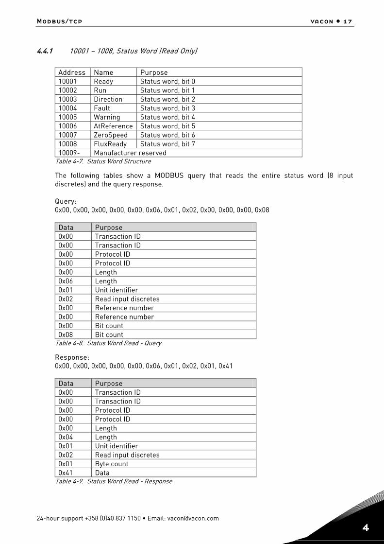
4.4.1 10001 – 1008, Status Word (Read Only)
Address Name Purpose 10001 Ready Status word, bit 0 10002 Run Status word, bit 1 10003 Direction Status word, bit 2 10004 Fault Status word, bit 3 10005 Warning Status word, bit 4 10006 AtReference Status word, bit 5 10007 ZeroSpeed Status word, bit 6 10008 FluxReady Status word, bit 7 10009- Manufacturer reserved
Table 4-7. Status Word Structure
The following tables show a MODBUS query that reads the entire status word (8 input discretes) and the query response. Query: 0x00, 0x00, 0x00, 0x00, 0x00, 0x06, 0x01, 0x02, 0x00, 0x00, 0x00, 0x08 Data Purpose 0x00 Transaction ID 0x00 Transaction ID 0x00 Protocol ID 0x00 Protocol ID 0x00 Length 0x06 Length 0x01 Unit identifier 0x02 Read input discretes 0x00 Reference number 0x00 Reference number 0x00 Bit count 0x08 Bit count
Table 4-8. Status Word Read - Query
Response: 0x00, 0x00, 0x00, 0x00, 0x00, 0x06, 0x01, 0x02, 0x01, 0x41 Data Purpose 0x00 Transaction ID 0x00 Transaction ID 0x00 Protocol ID 0x00 Protocol ID 0x00 Length 0x04 Length 0x01 Unit identifier 0x02 Read input discretes 0x01 Byte count 0x41 Data
Table 4-9. Status Word Read - Response
18 • vacon Modbus/TCP
Tel. +358 (0)201 2121 • Fax +358 (0)201 212 205
4
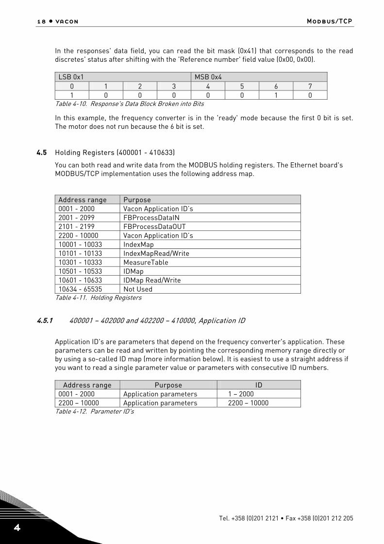
In the responses' data field, you can read the bit mask (0x41) that corresponds to the read discretes' status after shifting with the 'Reference number' field value (0x00, 0x00). LSB 0x1 MSB 0x4
0 1 2 3 4 5 6 7 1 0 0 0 0 0 1 0
Table 4-10. Response's Data Block Broken into Bits
In this example, the frequency converter is in the 'ready' mode because the first 0 bit is set. The motor does not run because the 6 bit is set.
4.5 Holding Registers (400001 - 410633)
You can both read and write data from the MODBUS holding registers. The Ethernet board's MODBUS/TCP implementation uses the following address map.
Address range Purpose 0001 - 2000 Vacon Application ID’s 2001 - 2099 FBProcessDataIN 2101 - 2199 FBProcessDataOUT 2200 - 10000 Vacon Application ID’s 10001 - 10033 IndexMap 10101 - 10133 IndexMapRead/Write 10301 - 10333 MeasureTable 10501 - 10533 IDMap 10601 - 10633 IDMap Read/Write 10634 - 65535 Not Used
Table 4-11. Holding Registers
4.5.1 400001 – 402000 and 402200 – 410000, Application ID
Application ID's are parameters that depend on the frequency converter's application. These parameters can be read and written by pointing the corresponding memory range directly or by using a so-called ID map (more information below). It is easiest to use a straight address if you want to read a single parameter value or parameters with consecutive ID numbers.
Address range Purpose ID 0001 - 2000 Application parameters 1 – 2000 2200 – 10000 Application parameters 2200 – 10000
Table 4-12. Parameter ID's
Modbus/tcp vacon • 19
24-hour support +358 (0)40 837 1150 • Email: [email protected]
4
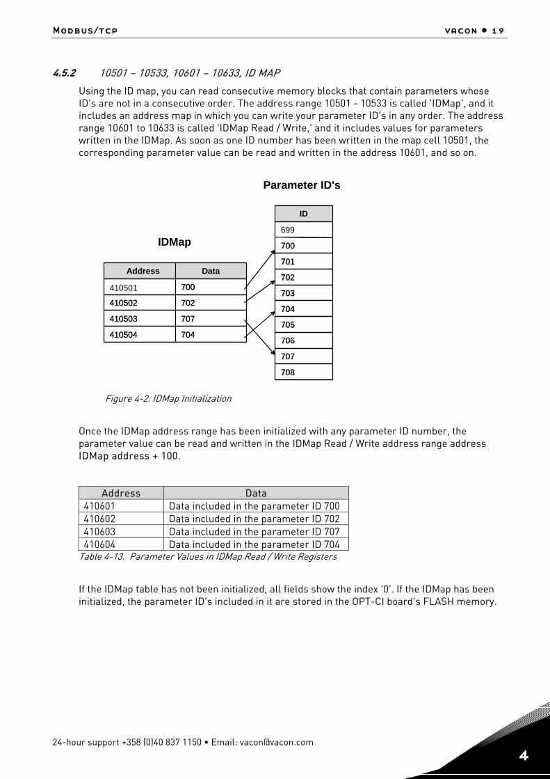
4.5.2 10501 – 10533, 10601 – 10633, ID MAP
Using the ID map, you can read consecutive memory blocks that contain parameters whose ID's are not in a consecutive order. The address range 10501 - 10533 is called 'IDMap', and it includes an address map in which you can write your parameter ID's in any order. The address range 10601 to 10633 is called 'IDMap Read / Write,' and it includes values for parameters written in the IDMap. As soon as one ID number has been written in the map cell 10501, the corresponding parameter value can be read and written in the address 10601, and so on.
Figure 4-2. IDMap Initialization
Once the IDMap address range has been initialized with any parameter ID number, the parameter value can be read and written in the IDMap Read / Write address range address IDMap address + 100.
Address Data 410601 Data included in the parameter ID 700 410602 Data included in the parameter ID 702 410603 Data included in the parameter ID 707 410604 Data included in the parameter ID 704
Table 4-13. Parameter Values in IDMap Read / Write Registers
If the IDMap table has not been initialized, all fields show the index '0'. If the IDMap has been initialized, the parameter ID's included in it are stored in the OPT-CI board's FLASH memory.
704 410504
707 410503
702 410502
700
Data Address
704 410504
707 410503
702 410502
700
Data Address
708
707
706
705
704
703
702
701
700
699
ID
708
707
706
705
704
703
702
701
700
ID
IDMap
Parameter ID's
410501
20 • vacon Modbus/TCP
Tel. +358 (0)201 2121 • Fax +358 (0)201 212 205
4
4.5.3 10001 – 10033, 10101 – 10133, Index MAP
IndexMap functions in almost entirely the same way as the IDMap. The difference between IndexMap and IDMap is that IndexMap is used to handle indexes instead of parameters. The address range 10001 – 10033 is called 'IndexMap' and you can write your index number in it. Correspondingly, the value of the written index can be read in the address range 10101 – 10133, called 'IndexMap Read / Write'. Also the data contained in the 'IndexMap' address range is stored in the OPT-CI board's FLASH memory. IndexMap data has a default value of 0.
4.5.4 402200 – 410000, FB Process Data Out (Read)
The 'Process data out' registers are mainly used for controlling frequency converters. You can read temporary values, such as frequency, voltage and moment, using the process data. The table values are updated every 10ms.
Address Purpose Range / Type
2101 FB Status Word See chapter 4.4.1 2102 FB General Status Word See chapter 4.3.1 2103 FB Actual Speed 0 .. 10 000 2104 FB Process Data out 1 See Appendix 1 2105 FB Process Data out 2 See Appendix 1 2106 FB Process Data out 3 See Appendix 1 2107 FB Process Data out 4 See Appendix 1 2108 FB Process Data out 5 See Appendix 1 2109 FB Process Data out 6 See Appendix 1 2110 FB Process Data out 7 See Appendix 1 2111 FB Process Data out 8 See Appendix 1
Table 4-14. Process Data Out
Modbus/tcp vacon • 21
24-hour support +358 (0)40 837 1150 • Email: [email protected]
4
4.5.5 402200 – 410000, FB Process Data In (Read / Write)
The use of process data depends on the application. Typically, the motor is started and stopped using the 'Control Word' and the speed is set by writing a 'Reference' value. Through using other process data fields, the device can give other required information to the MASTER device, depending on the application.
Address Purpose Range / Type 2001 FB Control Word See chapter 4.4.1 2002 FB General Control Word See chapter 4.3.1 2003 FB Speed Reference 0 .. 10 000 2004 FB Process Data in 1 See Appendix 1 2005 FB Process Data in 2 See Appendix 1 2006 FB Process Data in 3 See Appendix 1 2007 FB Process Data in 4 See Appendix 1 2008 FB Process Data in 5 See Appendix 1 2009 FB Process Data in 6 See Appendix 1 2010 FB Process Data in 7 See Appendix 1 2011 FB Process Data in 8 See Appendix 1
Table 4-15. Process Data In
4.5.6 10301 – 10333 Measurement Table
The measurement table provides 25 readable values as listed in the following table. The table values are updated every 100ms.
Address Purpose Type 10301 MotorTorque Integer 10302 MotorPower Integer 10303 MotorSpeed Integer 10304 FreqOut Integer 10305 FreqRef Integer 10306 REMOTEIndication Unsigned short 10307 MotorControlMode Unsigned short 10308 ActiveFault Unsigned short 10309 MotorCurrent Unsigned integer 10310 MotorVoltage Unsigned integer 10311 FreqMin Unsigned integer 10312 FreqScale Unsigned integer 10313 DCVoltage Unsigned integer 10314 MotorNomCurrent Unsigned integer 10315 MotorNomVoltage Unsigned integer 10316 MotorNomFreq Unsigned integer 10317 MotorNomSpeed Unsigned integer 10318 CurrentScale Unsigned integer 10319 MotorCurrentLimit Unsigned integer 10320 DecelerationTime Unsigned integer 10321 AccelerationTime Unsigned integer 10322 FreqMax Unsigned integer 10323 PolePairNumber Unsigned integer 10324 RampTimeScale Unsigned integer 10325 MsCounter Unsigned integer
Table 4-16. Measurement Table
22 • vacon Modbus/TCP
Tel. +358 (0)201 2121 • Fax +358 (0)201 212 205
4
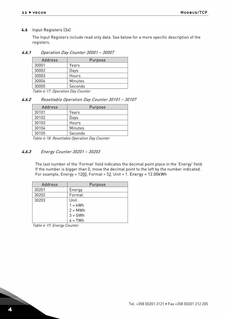
4.6 Input Registers (3x)
The Input Registers include read only data. See below for a more specific description of the registers.
4.6.1 Operation Day Counter 30001 – 30007
Address Purpose 30001 Years 30002 Days 30003 Hours 30004 Minutes 30005 Seconds
Table 4-17. Operation Day Counter
4.6.2 Resettable Operation Day Counter 30101 – 30107
Address Purpose 30101 Years 30102 Days 30103 Hours 30104 Minutes 30105 Seconds
Table 4-18. Resettable Operation Day Counter
4.6.3 Energy Counter 30201 – 30203
The last number of the 'Format' field indicates the decimal point place in the 'Energy' field. If the number is bigger than 0, move the decimal point to the left by the number indicated. For example, Energy = 1200, Format = 52. Unit = 1. Energy = 12.00kWh
Address Purpose 30201 Energy 30202 Format 30203 Unit
1 = kWh 2 = MWh 3 = GWh 4 = TWh
Table 4-19. Energy Counter
Modbus/tcp vacon • 23
24-hour support +358 (0)40 837 1150 • Email: [email protected]
4
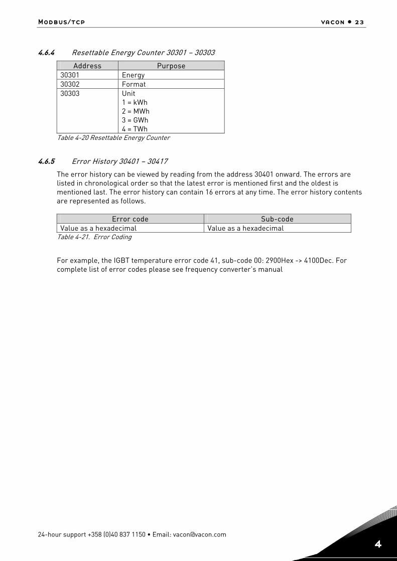
4.6.4 Resettable Energy Counter 30301 – 30303
Address Purpose 30301 Energy 30302 Format 30303 Unit
1 = kWh 2 = MWh 3 = GWh 4 = TWh
Table 4-20 Resettable Energy Counter
4.6.5 Error History 30401 – 30417
The error history can be viewed by reading from the address 30401 onward. The errors are listed in chronological order so that the latest error is mentioned first and the oldest is mentioned last. The error history can contain 16 errors at any time. The error history contents are represented as follows.
Error code Sub-code Value as a hexadecimal Value as a hexadecimal
Table 4-21. Error Coding
For example, the IGBT temperature error code 41, sub-code 00: 2900Hex -> 4100Dec. For complete list of error codes please see frequency converter’s manual

24 • vacon Start-up Test
Tel. +358 (0)201 2121 • Fax +358 (0)201 212 205
5
5. START-UP TEST
Once the option board has been installed and configured, its operation can be verified by writing a frequency instruction and giving a run command to the frequency converter via fieldbus.
5.1 Frequency Converter Settings
Select fieldbus as the active control bus. (For more information see the Vacon NX User´s Manual, section 7.3.3).
5.2 Master Unit Programming
1. Write a FB 'Control Word' (address: 42001) of value 1Hex 2. The frequency converter is now in the RUN mode. 3. Set the FB 'Speed Reference' (address:42003) value of 5000 ( = 50.00%). 4. The engine is now running at a 50% speed. 5. Write a 'FB Control Word' (address: 42001) value of 0Hex' 6. Following this, the engine stops.
Error codes and errors vacon • 25
24-hour support +358 (0)40 837 1150 • Email: [email protected]
6
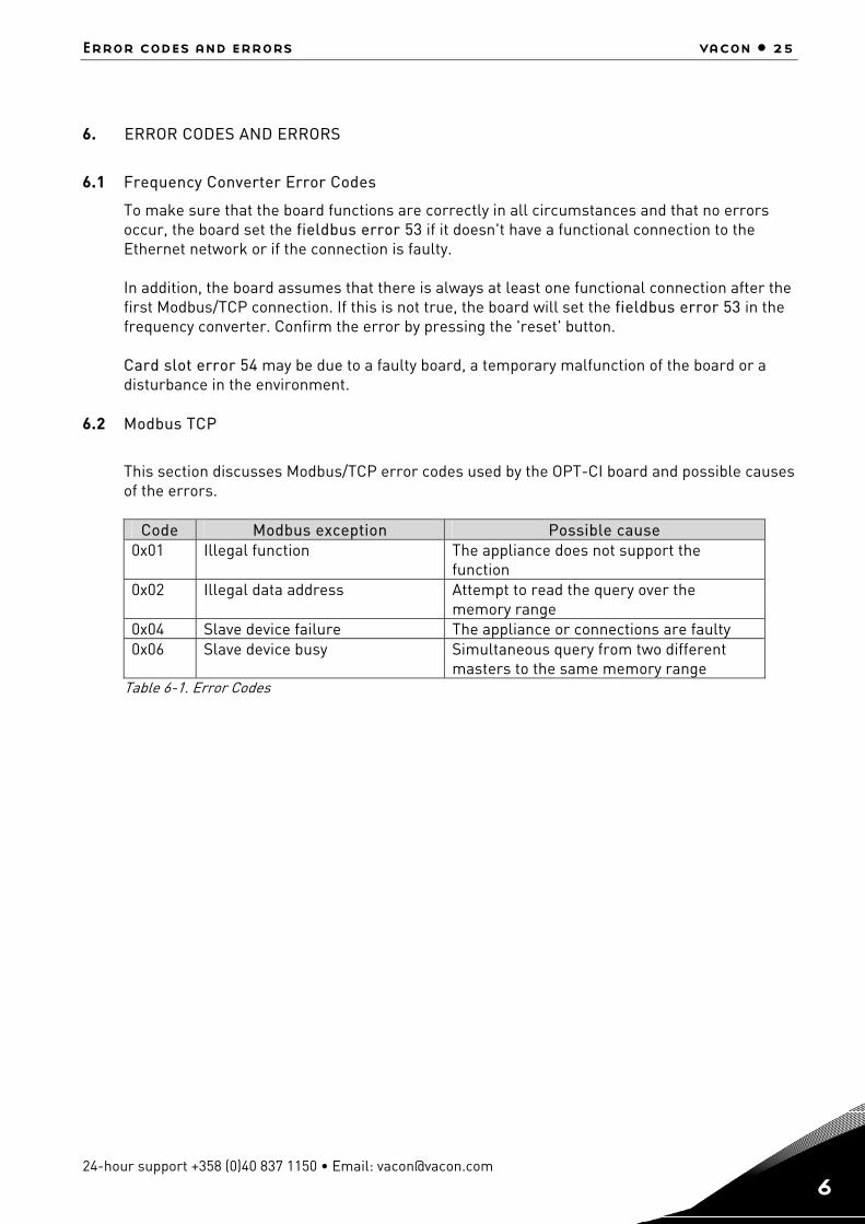
6. ERROR CODES AND ERRORS
6.1 Frequency Converter Error Codes
To make sure that the board functions are correctly in all circumstances and that no errors occur, the board set the fieldbus error 53 if it doesn't have a functional connection to the Ethernet network or if the connection is faulty. In addition, the board assumes that there is always at least one functional connection after the first Modbus/TCP connection. If this is not true, the board will set the fieldbus error 53 in the frequency converter. Confirm the error by pressing the 'reset' button. Card slot error 54 may be due to a faulty board, a temporary malfunction of the board or a disturbance in the environment.
6.2 Modbus TCP
This section discusses Modbus/TCP error codes used by the OPT-CI board and possible causes of the errors.
Code Modbus exception Possible cause
0x01 Illegal function The appliance does not support the function
0x02 Illegal data address Attempt to read the query over the memory range
0x04 Slave device failure The appliance or connections are faulty 0x06 Slave device busy Simultaneous query from two different
masters to the same memory range Table 6-1. Error Codes
26 • vacon Appendix
Tel. +358 (0)201 2121 • Fax +358 (0)201 212 205
7
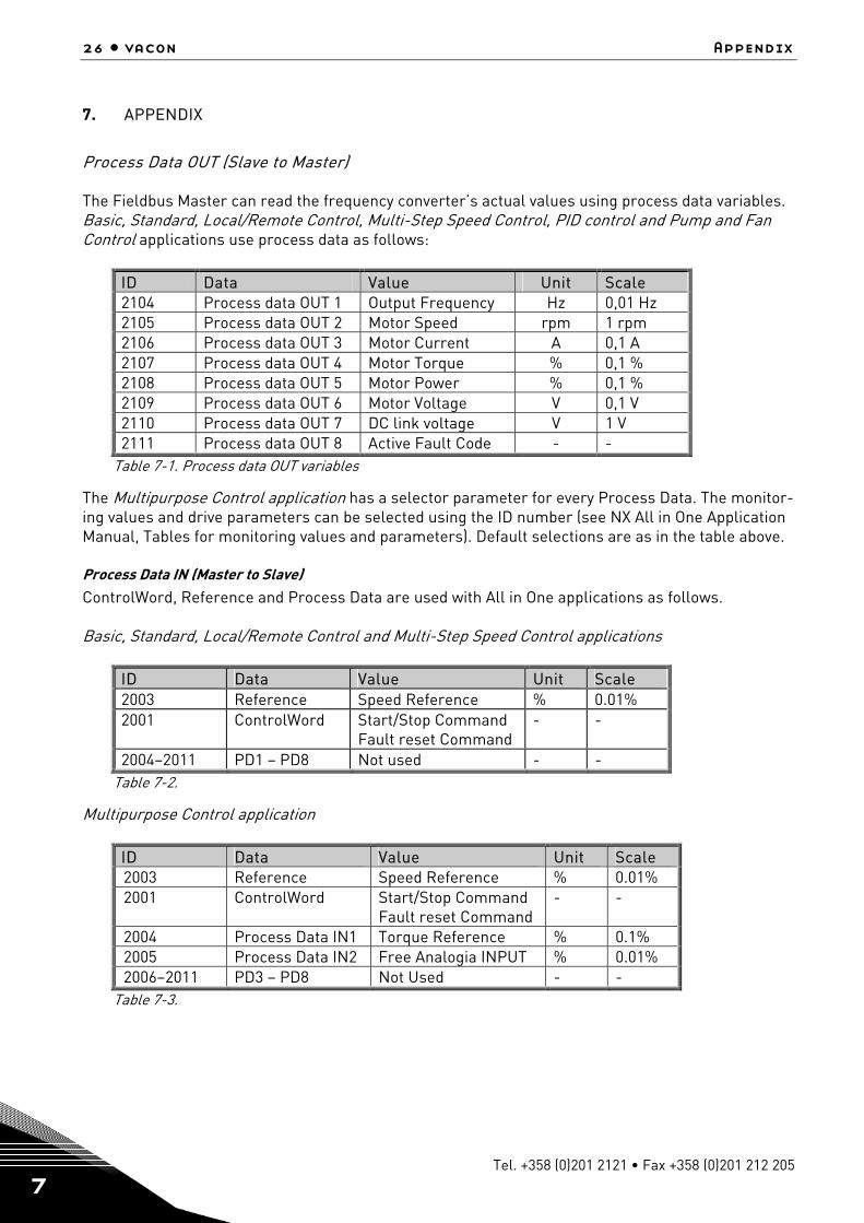
7. APPENDIX
Process Data OUT (Slave to Master) The Fieldbus Master can read the frequency converter’s actual values using process data variables. Basic, Standard, Local/Remote Control, Multi-Step Speed Control, PID control and Pump and Fan Control applications use process data as follows:
ID Data Value Unit Scale 2104 Process data OUT 1 Output Frequency Hz 0,01 Hz 2105 Process data OUT 2 Motor Speed rpm 1 rpm 2106 Process data OUT 3 Motor Current A 0,1 A 2107 Process data OUT 4 Motor Torque % 0,1 % 2108 Process data OUT 5 Motor Power % 0,1 % 2109 Process data OUT 6 Motor Voltage V 0,1 V 2110 Process data OUT 7 DC link voltage V 1 V 2111 Process data OUT 8 Active Fault Code - -
Table 7-1. Process data OUT variables
The Multipurpose Control application has a selector parameter for every Process Data. The monitor-ing values and drive parameters can be selected using the ID number (see NX All in One Application Manual, Tables for monitoring values and parameters). Default selections are as in the table above. Process Data IN (Master to Slave) ControlWord, Reference and Process Data are used with All in One applications as follows. Basic, Standard, Local/Remote Control and Multi-Step Speed Control applications
ID Data Value Unit Scale 2003 Reference Speed Reference % 0.01% 2001 ControlWord Start/Stop Command
Fault reset Command - -
2004–2011 PD1 – PD8 Not used - - Table 7-2.
Multipurpose Control application
ID Data Value Unit Scale 2003 Reference Speed Reference % 0.01% 2001 ControlWord Start/Stop Command
Fault reset Command - -
2004 Process Data IN1 Torque Reference % 0.1% 2005 Process Data IN2 Free Analogia INPUT % 0.01% 2006–2011 PD3 – PD8 Not Used - -
Table 7-3.
appendix vacon • 27
24-hour support +358 (0)40 837 1150 • Email: [email protected]
7
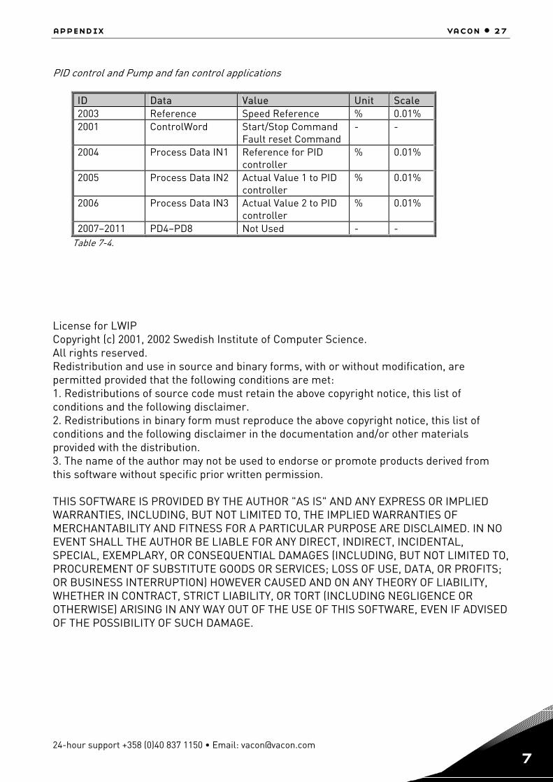
PID control and Pump and fan control applications
ID Data Value Unit Scale 2003 Reference Speed Reference % 0.01% 2001 ControlWord Start/Stop Command
Fault reset Command - -
2004 Process Data IN1 Reference for PID controller
% 0.01%
2005 Process Data IN2 Actual Value 1 to PID controller
% 0.01%
2006 Process Data IN3 Actual Value 2 to PID controller
% 0.01%
2007–2011 PD4–PD8 Not Used - - Table 7-4.
License for LWIP Copyright (c) 2001, 2002 Swedish Institute of Computer Science. All rights reserved. Redistribution and use in source and binary forms, with or without modification, are permitted provided that the following conditions are met: 1. Redistributions of source code must retain the above copyright notice, this list of conditions and the following disclaimer. 2. Redistributions in binary form must reproduce the above copyright notice, this list of conditions and the following disclaimer in the documentation and/or other materials provided with the distribution. 3. The name of the author may not be used to endorse or promote products derived from this software without specific prior written permission. THIS SOFTWARE IS PROVIDED BY THE AUTHOR "AS IS" AND ANY EXPRESS OR IMPLIED WARRANTIES, INCLUDING, BUT NOT LIMITED TO, THE IMPLIED WARRANTIES OF MERCHANTABILITY AND FITNESS FOR A PARTICULAR PURPOSE ARE DISCLAIMED. IN NO EVENT SHALL THE AUTHOR BE LIABLE FOR ANY DIRECT, INDIRECT, INCIDENTAL, SPECIAL, EXEMPLARY, OR CONSEQUENTIAL DAMAGES (INCLUDING, BUT NOT LIMITED TO, PROCUREMENT OF SUBSTITUTE GOODS OR SERVICES; LOSS OF USE, DATA, OR PROFITS; OR BUSINESS INTERRUPTION) HOWEVER CAUSED AND ON ANY THEORY OF LIABILITY, WHETHER IN CONTRACT, STRICT LIABILITY, OR TORT (INCLUDING NEGLIGENCE OR OTHERWISE) ARISING IN ANY WAY OUT OF THE USE OF THIS SOFTWARE, EVEN IF ADVISED OF THE POSSIBILITY OF SUCH DAMAGE.
Vaasa Vacon Plc (Head office and production) Runsorintie 7 65380 Vaasa [email protected] telephone: +358 (0)201 2121 fax: +358 (0)201 212 205
Helsinki Vacon Plc Äyritie 12 01510 Vantaa telephone: +358 (0)201 212 600 fax: +358 (0)201 212 699 Tampere Vacon Plc Vehnämyllynkatu 18 33700 Tampere telephone: +358 (0)201 2121 fax: +358 (0)201 212 750
Vacon Traction Oy Vehnämyllynkatu 18 33700 Tampere telephone: +358 (0)201 2121 fax: +358 (0)201 212 710
sales companies and representative offices:
Austria Vacon AT Antriebssysteme GmbH Aumühlweg 21 2544 Leobersdorf telephone: +43 2256 651 66 fax: +43 2256 651 66 66 Belgium Vacon Benelux NV/SA Interleuvenlaan 62 3001 Heverlee (Leuven) telephone: +32 (0)16 394 825 fax: +32 (0)16 394 827 France Vacon France s.a.s. ZAC du Fresne 1 Rue Jacquard – BP72 91280 Saint Pierre du Perray CDIS telephone: +33 (0)1 69 89 60 30 fax: +33 (0)1 69 89 60 40 Germany Vacon GmbH Gladbecker Strasse 425 45329 Essen telephone: +49 (0)201 806 700 fax: +49 (0)201 806 7099 Great Britain Vacon Drives (UK) Ltd. 18, Maizefield Hinckley Fields Industrial Estate Hinckley LE10 1YF Leicestershire telephone: +44 (0)1455 611 515 fax: +44 (0)1455 611 517
Italy Vacon S.p.A. Via F.lli Guerra, 35 42100 Reggio Emilia telephone: +39 0522 276811 fax: +39 0522 276890 The Netherlands Vacon Benelux BV Weide 40 4206 CJ Gorinchem telephone: +31 (0)183 642 970 fax: +31 (0)183 642 971 Norway Vacon AS Langgata 2 3080 Holmestrand telephone: +47 330 96120 fax: +47 330 96130 PR China Vacon Suzhou Drives Co. Ltd. Building 13CD 428 Xinglong Street Suchun Industrial Square Suzhou 215126 telephone: +86 512 6283 6630 fax: +86 512 6283 6618
Vacon Suzhou Drives Co. Ltd. Beijing Office A205, Grand Pacific Garden Mansion 8A Guanhua Road Beijing 100026 telephone: +86 10 6581 3734 fax: +86 10 6581 3754
Russia ZAO Vacon Drives Bolshaja Jakimanka 31, stroenie 18 109180 Moscow telephone: +7 (095) 974 14 47 fax: +7 (095) 974 15 54
ZAO Vacon Drives 2ya Sovetskaya 7, office 210A 191036 St. Petersburg telephone: +7 (812) 332 1114 fax: +7 (812) 279 9053 Singapore Vacon Plc Singapore Representative Office 102F Pasir Panjang Road #02-06 Citilink Warehouse Complex Singapore 118530 telephone: +65 6278 8533 fax: +65 6278 1066 Spain Vacon Drives Ibérica S.A. Miquel Servet, 2. P.I. Bufalvent 08243 Manresa telephone: +34 93 877 45 06 fax: +34 93 877 00 09 Sweden Vacon AB Torget 1 172 67 Sundbyberg telephone: +46 (0)8 293 055 fax: +46 (0)8 290 755
Vacon distributor: