Embed Size (px)
Citation preview

v5055Honeywell Industrial
GasValves’
1-3 Inch Valves 4 Inch Valves
Gas Flowvs0
ValveOpening

Table of Contents
PAGE
INTRODUCTION . . . . . . . . . . . . . . . . . . . . . 1
VALVE CURVES . . . . . . . . . . . . . . . . . . . . . 1
V5055A.D . . . . . . . . . . . . . . . . . . . . . . 1
V5055B . . . . . . . . . . . . . . . . . . . . . . . 5
V5055C.E . . . . . . . . . . . . . . . . . . . . . . . 9
CAPACITYCURVES . . . . . . . . . . . . . . . . . . . 13
VALVE SlZlNG CHART . . . . . . . . . . . . . . . . . . . 14

1 60-2307—10
V5055A-EIndustrial Gas Valves
The V5055 Gas Valves are used with the V4055,V4062, and V9055 Fluid Power Actuators to con-trol gas flow to commercial and industrial burners.
■ Used with natural or liquefied petroleum (LP) gases.
■ V5055 normally closed valves are rated for finalshutoff service (safety shutoff).
■ V5055A,C,D,E Valves are for On-Off service.
■ V5055B Valve has a characterized guide and incombination with the V4055, V4062, and V9055Fluid Power Actuators, provides slow-opening, hi-lo-off, and modulating functions respectively.
■ V5055C,E Valves have a double seal and are usedwith V4055D,E Actuators to provide proof-of-clo-sure switch and valve seal overtravel interlock.
■ V5055D,E Valves are for high pressure applications(see Table 1).
■ Seven valve sizes from 3/4 to 3 inches have NPTthreaded connections. Models are available withBSP-PL threads. V5055A,B,C Valves are availablein a 4 inch size and have flange connections.
■ Most models have 1/4 inch upstream and down-stream top and plug. BSP-PL thread models have1/4 inch upstream tap and plug.
■ Valve body rating of 75 psi (517.1 kPa).
■ Yellow SHUT indicator attached to the valve stemprovides an indication of the valve closed position.
■ Unpainted, die-cast aluminum body.
F. P. • Rev. 11-94 • ©Honeywell Inc. 1994 • Form Number 60-2307—10
CONTENTS
Specifications ................................................. 2Ordering Information ..................................... 2Installation ..................................................... 6Operation and Checkout ................................ 8Service Information ........................................ 9

60-2307—10 2
V5055A-ESPECIFICATIONS • ORDERING INFORMATION
SpecificationsMODELS:
V5055A Industrial Gas Valve for On-Off service.V5055B Industrial Gas Valve with characterized guide
for slow opening, HI-LO-OFF, or modulating service.V5055C: Same as V5055A but incorporates a double
seal. Used with the V4055D Actuator to a provideproof-of-closure switch and a valve seal overtravelinterlock.
V5055D: Same as V5055A but for high pressure appli-cations.
V5055E: Same as V5055C but for high pressure appli-cations.
TYPE OF GAS: Natural or liquefied petroleum (LP) only.PIPE SIZE: 3/4, 1, 1-1/4, 1-1/2, 2, 2-1/2, 3, and 4 in. (only
V5055A,B,C available in 4 in. size).PIPE THREADS: NPT or BSP-PL Threads (equivalent to
ISO R7 and DIN 2999). Available on inlet and outlet of3/4 to 3 inch valves. Four inch valves have flange connec-tions.
PRESSURE RATINGS: See Table 1.VALVE BODY RATING: 75 psi (517.1 kPa).VALVE CAPACITIES: A.G.A. ratings at 1 in. (0.25 kPa)
pressure drop; based on gas with specific gravity of 0.64.
TABLE 1—PRESSURE RATINGS OF VALVE-ACTUATOR COMBINATIONS.
a Maximum operating pressure differential.b Maximum close-off pressure without seal leakage. This is the maximum allowable pressure drop to which a valve may be
subjected while fully closed, and is independent of the valve body rating.c Use a V4055D, V4055E, V4062D, or V9055D (with proof-of-closure switch) with a V5055C or E (with double seal) for valve
seal overtravel interlock.
Actuator
V4055A,Dc V4055B,Ec V4062,V9055c
Valve psi kPa psi kPa psi kPa psi kPa psi kPa psi kPa
V5055A,C 3/4 to 3 in.
5 34.5 15 103.4 15 103.4 15 103.4 5 34.5 14 103.4
V5055A,C 4 in.
3 20.7 15 103.4 5 34.5 15 103.4 3 20.7 15 103.4
V4055B 3/4 to 3 in.
5 34.5 15 103.4 15 103.4 15 103.4 5 34.5 15 103.4
V5055B 4 in.
3 20.7 15 103.4 5 34.5 15 103.4 3 20.7 15 103.4
V5055D,E 3/4, 1, 1-1/4, 1-1/2 in.
5 34.5 75 517.1 25 172.4 75 517.1 5 34.5 75 517.1
V5055D,E 2, 2-1/2, 3 in.
5 34.5 45 310.3 15 103.4 45 310.3 5 34.5 45 310.3
Ordering InformationWhen purchasing replacement and modernization products from your TRADELINE® wholesaler or distributor, refer to the TRADELINE®
Catalog or price sheets for complete ordering number, or specify—1. Order number2. Pipe size.3. NPT or parallel BSP threads (except for 4 in. models with flanges).4. Optional additional tapping and plug—1/8 in downstream and/or 1/2 in. upstream.5. Replacement parts, if desired.
If you have additional questions, need further information, or would like to comment on our products or services, please writeor phone:
1. Your local Home and Building Control Sales Office (please check the white pages of your phone directory).2. Home and Building Control Customer Logistics
Honeywell Inc.1885 Douglas Drive NorthMinneapolis, Minnesota 55422-4386 (612) 951-1000
In Canada—Honeywell Limited/Honeywell Limitée, 740 Ellesmere Road, Scarborough, Ontario M1P2V9. International Sales andService Offices in all principal cities of the world. Manufacturing in Australia, Canada, Finland, France, Germany, Japan, Mexico,Netherlands, Spain, Taiwan, United Kingdom, U.S.A.

3 60-2307—10
V5055A-ESPECIFICATIONS
UPSTREAM TAPPING AND PLUG: 1 /4 in. NPT or BSP-PL is standard.
DOWNSTREAM TAPPING AND PLUG:1/4 in. NPT on most domestic models.1/8 in. NPT on V5055C1182.
AMBIENT OPERATING TEMPERATURE RATING:-40°F to 150°F (-40°C to 66°C); -40°F to 125°F(-40°C to 52°C) when used with V9055.
MATERIAL: Die-cast aluminum.MOUNTING: Mounts directly in the gas supply line.DIMENSIONS: See Fig. 2 and 3.WEIGHT:
3/4, 1, 1-1/4, 1-1/2, in. valve: 4 lb. (1.8 kg).2 in. valve: 8 lb. (3.6 kg).2-1/2, 3 in. valve: 11 lb. (5.0 kg).4 in. valve: 28 lb. (12.7 kg).
I.A.S.a Rated CapacityValve Size (in.) cf/h cu m/hr
3/4 665 18.8
1 960 27.2
1-1/4 1406 39.8
1-1/2 1717 48.6
2 3620 102.5
2-1/2 4250 120.3
3 5230 148.1
4 (V5055A) 10200 288.8
4 (V5055B,C) 9180 259.9a A joint venture of CGA Approvals Inc. and AGA Labora-
tories.
Fig. 1—Flow curves for V5055 Valves.
M9542
100 (2.8)
11 2 3 4 5 6 7 8 9 1 2 3 4 5 6 7 8 9 1 2 3 4 5 6 7 8 9 1
9876
5
4
3
2
19876
5
4
3
2
11.0 (0.25)
10.0 (2.5)
100.0 (25)
.9
.8
.7
.6
.5
.4
.3
.2
.1
100.09876
5
4
3
2
1.09876
5
4
3
2
1.0.9.8.7.6
.5
.4
.3
.2
.11000 (28)
10,000 (283)
100,000 (2830)
CAPACITY, IN CUBIC FEET PER HOUR (cf/h) FOR GAS WITH SPECIFIC GRAVITY OF 0.64 [1 cf/h = 0.0283 cu m/hr]
PR
ES
SU
RE
DR
OP
, IN
CH
ES
WC
[1
in. w
c =
0.25
kP
a]
3/4
INC
H
1 IN
CH
1 IN
CH
1 1/
4 IN
CH
1 1/
2 IN
CH
2 IN
CH
2 1/
2 IN
CH
3 IN
CH
4 IN
CH
V50
55B
, C4
INC
H V
5055
A
60-2307—10 4
V5055A-ESPECIFICATIONS
REPLACEMENT PARTS:Replacement Seal Assembly: Includes valve seal, bonnetseal, and tube of lubricant.
133393A: for 3/4, 1, 1-1/4, and 1-1/2 in. valves133392A: for 2, 2-1/2, and 3 in. valves.137253A: for 4 in. valves.
Replacement Bonnet Assembly: Includes complete bon-net assembly, plus the required replacement seal assem-bly.
APPROVALS: The following combinations of V5055 Valves(3/4 through 4 in.) and V4055, V4062 and V9055 FluidPower Actuators are approved by these agencies:
Underwriters Laboratories Inc. Listed: (File No. MH1639,Guide No. YIOZ):V4055A,B,D,E/V5055A,B,C,D,EV4062/V5055A,B,C,EV9055/V5055A,B,C,E
Valve Model
Valve Size (in.)
ReplacementBonnet
AssemblyV5055A (On-Off) 3/4, 1, 1-1/4,
1-1/2133398AA
2, 2-1/2, 3 133417AA
4 136911AA
V5055B(Characterized guide)
3/4, 1, 1-1/4,1-1/2
133398BA
2, 2-1/2, 3 133417BA
4 136911BA
V5055C (Valve-closed indicator)
4 136911CA
V5055D (Highpressure On-Off)
3/4, 1, 1-1/4,1-1/2
136308AA
2, 2-1/2, 3 136307AA
Fig. 2—Approximate dimensions of the 3/4 through 3 in. V5055 Valves with valve actuator in in. (mm).
B
E
F
C
D
A 1
1/4 INCH NPT DOWNSTREAM TAP AND PLUG
1/4 INCH NPT UPSTREAM TAP AND PLUG
1
(32.5)
KNOCKOUT FOR1/2 INCH CONDUIT (4)
OCTAGON
19 32
27
32(21.4)
3 23
325 (127)
(94.5)
63 4
(171.5)
ALLOW 2 IN. (51 mm) CLEARANCE FOR ACTUATOR REMOVAL.
M9585
3/4
1
1-1/4
1-1/2
2
2-1/2
3
VALVE SIZE INCH
11-1/8
11-1/8
11-1/8
11-1/8
11-1/4
11-3/4
11-3/4
282.6
282.6
282.6
282.6
285.8
298.5
298.5
2-3/4
2-3/4
2-3/4
2-3/4
2-7/8
3-3/8
3-3/8
69.9
69.9
69.9
69.9
73.0
85.7
85.7
8-3/16
8-3/16
8-3/16
8-3/16
8-5/16
8-13/16
8-13/16
208.0
208.0
208.0
208.0
211.1
223.8
223.8
5-3/4
5-3/4
5-3/4
5-3/4
8-3/8
9-1/4
9-1/4
146.1
146.1
146.1
146.1
212.7
235.0
235.0
2-1/4
2-1/4
2-1/4
2-1/4
2-3/4
2-3/4
2-3/4
57.2
57.2
57.2
57.2
69.9
69.9
69.9
4-13/16
4-13/16
4-13/16
4-13/16
7-19/32
7-19/32
7-19/32
122.2
122.2
122.2
122.2
192.9
192.9
192.9
2-13/16
2-13/16
2-13/16
2-13/16
3-1/2
4-1/2
4-1/2
71.4
71.4
71.4
71.4
88.9
114.3
114.3
DIM A
IN. MM
DIM B
IN. MM
DIM C
IN. MM
DIM D
IN. MM
DIM E
IN. MM
DIM F
IN. MM
OCTAGON
IN. MM
5 60-2307—10
V5055A-ESPECIFICATIONS
Industrial Risk Insurers (Formerly F.L.A.) Acceptable:V4055A,B,D,E/V5055A,B,C,D,EV4062/V5055A,B,C,EV9055/V5055A,B,C,E
Factory Mutual Approved (Report No. 20698, 20835, 21172,and 24061).
American Gas Association (IAS) Design Certified (ReportNo. 21 -1 C):V4055A/V4055A,B V4055E/V5055EV4055B/V5055D V4062/V5055B,CV4055D/V5055C V9055/V5055B,C
NOTE: The IAS does not certify models equipped with BSPthreads.
Canadian Gas Approvals Inc. (IAS) Certified (Report No.1029-SSV-4098, 60 Hz actuator models only):V4055A,B,D,E/V5055A,B,C,D,EV4062/V5055BV9055/V5055B
British Gas Corporation and Dutch Gas Institute Approved:V4055 or V4062 with V5055; A1145, -A1152, A1160,-A1178, -B1168, -B1184, B1192, -B1200, -B1218.
Australian Gas Association Approved: V5055; -B1267,-B1275, and -B1291.
DIN-DVGW Approved (Germany): V5055, -A1145,-A1152, -A1160, -A1178, -B1168, -B1184, -B1192,-B1200, and -B1218.
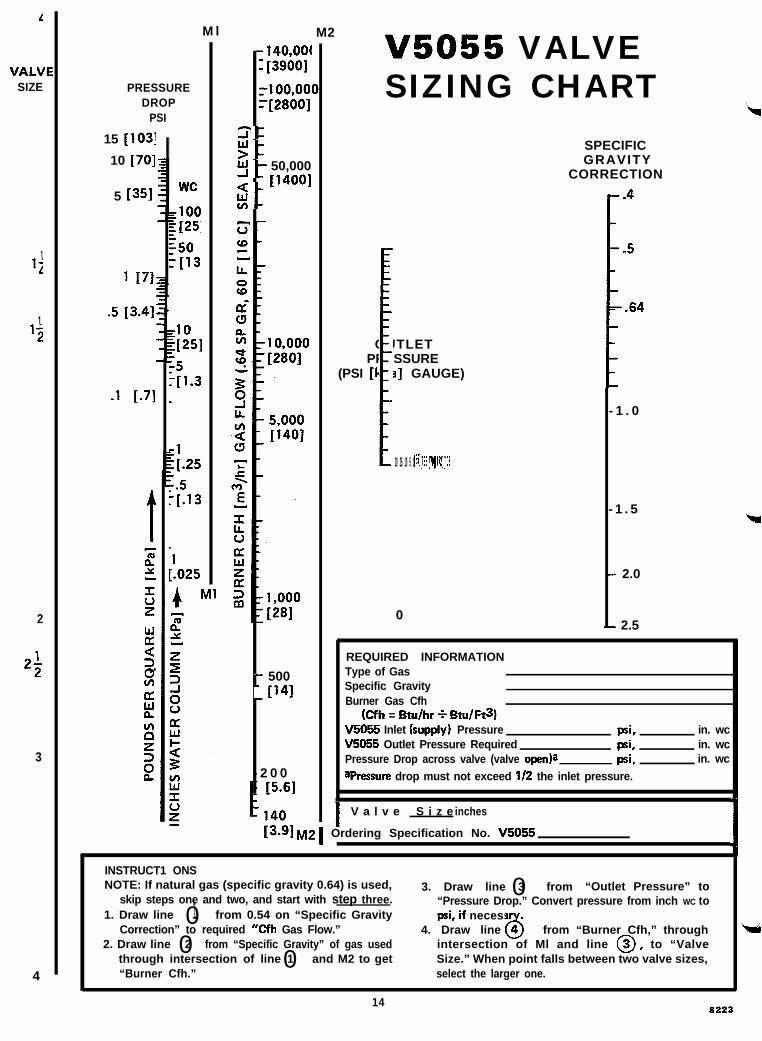
GAS VALVE SIZING1. Check the burner nameplate for (a) the type of gas
used, and (b) the gas flow capacity. The capacity will belisted in Btu/h (Btus per hour) or in cf/h (cubic foot per hour).
2. Call the gas utility for information on (a) the specificgravity (sp gr) and (b) Btu per cubic foot (Btu/cu ft) for typeof gas used.
3. Find the capacity in cf/h. If the capacity is listed inBtu/h, convert to cfh by the following formula:
Btu/h (from burner nameplate)
Btu/cu ft (from gas utility)Capacity in cf/h =
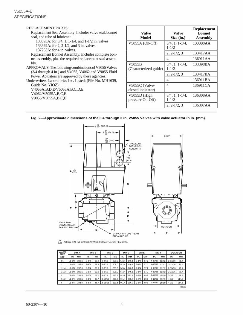
Fig. 3—Approximate dimensions of the 4 in. V5055 Valves with valve actuator in in. (mm).
117 32
(285)
525 32
(147)
M9584
1
(33)
KNOCKOUT FOR1/2 INCH CONDUIT (4)
19
32
27
32(21.4)
3 23
32
5 (127)
(94.5)
63 4
(171.5)
95 32
3 4
5 32
(233)
(360)
2
45° (16)
1 ALLOW 2 IN. (51 mm) CLEARANCE ABOVE V4055 SO IT MAY BE REMOVED FROM VALVE. DIMENSIONS ON DIN-APPROVED VALVES: 1/4 - 19 BSP.PL UPSTREAM PLUG (2), .71 IN (18 mm) DIAMETER BOLT HOLE (16), 7.087 IN (180 mm) DIAMETER BOLT CIRCLE.
2
14
(19)
DIAMETER (16)
1 2
7 (191)1 2
12 (318)DIAMETER 4 (102)
DIAMETER
1/4 - 18 NPT UPSTREAM PLUG (2)
60-2307—10 6
V5055A-ESPECIFICATIONS • INSTALLATION
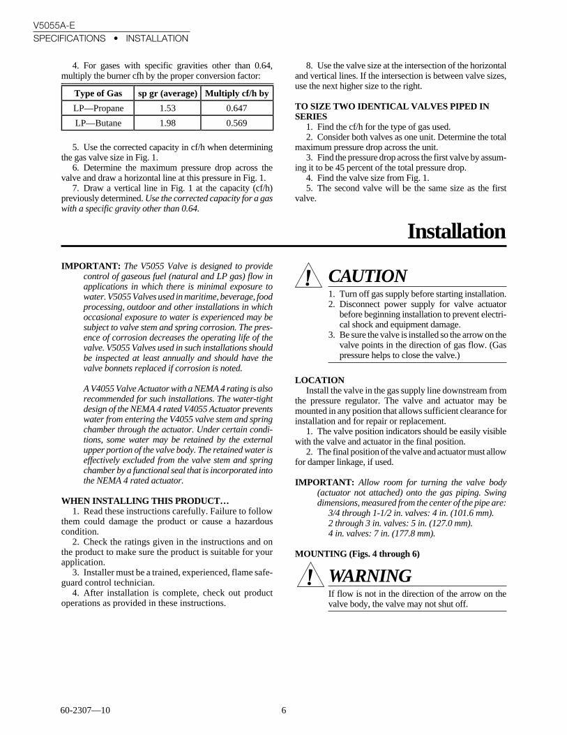
4. For gases with specific gravities other than 0.64,multiply the burner cfh by the proper conversion factor:
8. Use the valve size at the intersection of the horizontaland vertical lines. If the intersection is between valve sizes,use the next higher size to the right.
TO SIZE TWO IDENTICAL VALVES PIPED INSERIES
1. Find the cf/h for the type of gas used.2. Consider both valves as one unit. Determine the total
maximum pressure drop across the unit.3. Find the pressure drop across the first valve by assum-
ing it to be 45 percent of the total pressure drop.4. Find the valve size from Fig. 1.5. The second valve will be the same size as the first
valve.
5. Use the corrected capacity in cf/h when determiningthe gas valve size in Fig. 1.
6. Determine the maximum pressure drop across thevalve and draw a horizontal line at this pressure in Fig. 1.
7. Draw a vertical line in Fig. 1 at the capacity (cf/h)previously determined. Use the corrected capacity for a gaswith a specific gravity other than 0.64.
InstallationIMPORTANT: The V5055 Valve is designed to provide
control of gaseous fuel (natural and LP gas) flow inapplications in which there is minimal exposure towater. V5055 Valves used in maritime, beverage, foodprocessing, outdoor and other installations in whichoccasional exposure to water is experienced may besubject to valve stem and spring corrosion. The pres-ence of corrosion decreases the operating life of thevalve. V5055 Valves used in such installations shouldbe inspected at least annually and should have thevalve bonnets replaced if corrosion is noted.
A V4055 Valve Actuator with a NEMA 4 rating is alsorecommended for such installations. The water-tightdesign of the NEMA 4 rated V4055 Actuator preventswater from entering the V4055 valve stem and springchamber through the actuator. Under certain condi-tions, some water may be retained by the externalupper portion of the valve body. The retained water iseffectively excluded from the valve stem and springchamber by a functional seal that is incorporated intothe NEMA 4 rated actuator.
WHEN INSTALLING THIS PRODUCT…1. Read these instructions carefully. Failure to follow
them could damage the product or cause a hazardouscondition.
2. Check the ratings given in the instructions and onthe product to make sure the product is suitable for yourapplication.
3. Installer must be a trained, experienced, flame safe-guard control technician.
4. After installation is complete, check out productoperations as provided in these instructions.
CAUTION1. Turn off gas supply before starting installation.2. Disconnect power supply for valve actuator
before beginning installation to prevent electri-cal shock and equipment damage.
3. Be sure the valve is installed so the arrow on thevalve points in the direction of gas flow. (Gaspressure helps to close the valve.)
LOCATIONInstall the valve in the gas supply line downstream from
the pressure regulator. The valve and actuator may bemounted in any position that allows sufficient clearance forinstallation and for repair or replacement.
1. The valve position indicators should be easily visiblewith the valve and actuator in the final position.
2. The final position of the valve and actuator must allowfor damper linkage, if used.
IMPORTANT: Allow room for turning the valve body(actuator not attached) onto the gas piping. Swingdimensions, measured from the center of the pipe are:
3/4 through 1-1/2 in. valves: 4 in. (101.6 mm).2 through 3 in. valves: 5 in. (127.0 mm).4 in. valves: 7 in. (177.8 mm).
MOUNTING (Figs. 4 through 6)
WARNINGIf flow is not in the direction of the arrow on thevalve body, the valve may not shut off.
Type of Gas sp gr (average) Multiply cf/h by
LP—Propane 1.53 0.647
LP—Butane 1.98 0.569

7 60-2307—10
V5055A-EINSTALLATION
1. Use new, properly reamed, pipe, free from chips.2. Do not thread pipe too far (Fig. 4). Valve distortion or
malfunction may result from excess pipe in the valve.
Fig. 4—Preparing the pipes.
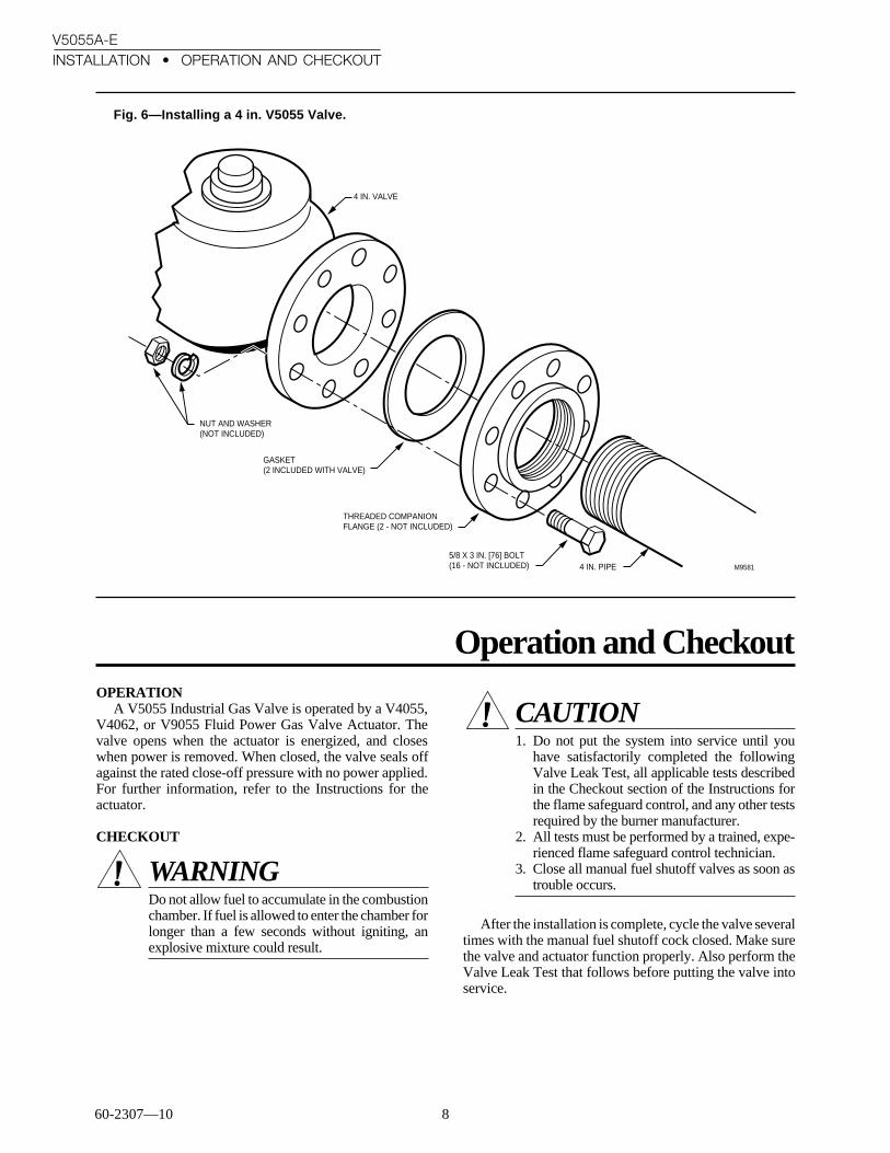
8. Use two threaded companion flanges, two gaskets(included with valve), and 16 bolts (with washers and nuts)for mounting a 4 in.-V5055 Valve. Mount a threaded flangeand gasket on each end of the valve as shown in Fig. 6. Thenscrew the pipes into the threaded flanges. Apply dope spar-ingly, and use wrenches and vises properly as shown in Fig.4 and 5.
9. Make sure the power supply is disconnected from thevalve actuator. Then mount the actuator on the valve bodyand complete the electrical and linkage connections follow-ing the instructions packed with the actuator.
Fig. 5—Installing a 3/4 through 3 in. V5055Valve.
CORRECT:VISE GRIPS END NEXT TO PIPE BEING INSERTED
CORRECT:WRENCH CORRECTLY APPLIED NEXT TO PIPE BEING INSERTED
INCORRECT:WRENCH HERE STRAINS VALVE BODY
M9580
3. Remove the protective caps from the ends of the valve.Do not attach the valve actuator until the valve body instal-lation is complete.
4. Apply good quality pipe dope resistant to action of LPgas, putting a moderate amount on the male threads only.Use dope sparingly; if pipe dope lodges on the valve seat, itwill prevent proper closure.
5. Install valve with the gas flow in the direction indi-cated by the arrow on the casting.
6. Apply a parallel jaw wrench only to the flat next to thepipe being inserted (Fig. 5). A wrench applied to the valvebody itself, or to the end farthest from the pipe being inserted,may distort the casting, causing a malfunction. Do not use thevalve for a lever.
7. Be sure the gas flow is in the same direction as thearrow on the bottom of the valve body.
INCORRECT:
CORRECT:
TWO CLEAN THREADS, MODERATE AMOUNT OF DOPE
EXCESS DOPE MAY BLOCK DISK OFF VALVE SEAT
LOOSE CHIPS
NORMAL FULL THREAD
CORRECT:NORMAL FULL THREAD
REAM PIPE, BLOW OUT CHIPS (TO AVOID LODGING ON SEAT)
TOO LONG, DISTORTS VALVE SEAT
INCORRECT:TOO LONG, DISTORTS VALVE SEAT
M95711
1
USE PIPE DOPE RESISTANT TO ACTION OF LP GAS.
60-2307—10 8
V5055A-EINSTALLATION • OPERATION AND CHECKOUT
Fig. 6—Installing a 4 in. V5055 Valve.
Operation and Checkout
NUT AND WASHER (NOT INCLUDED)
4 IN. VALVE
4 IN. PIPE M9581
GASKET (2 INCLUDED WITH VALVE)
THREADED COMPANION FLANGE (2 - NOT INCLUDED)
5/8 X 3 IN. [76] BOLT (16 - NOT INCLUDED)
OPERATIONA V5055 Industrial Gas Valve is operated by a V4055,
V4062, or V9055 Fluid Power Gas Valve Actuator. Thevalve opens when the actuator is energized, and closeswhen power is removed. When closed, the valve seals offagainst the rated close-off pressure with no power applied.For further information, refer to the Instructions for theactuator.
CHECKOUT
WARNINGDo not allow fuel to accumulate in the combustionchamber. If fuel is allowed to enter the chamber forlonger than a few seconds without igniting, anexplosive mixture could result.
CAUTION1. Do not put the system into service until you
have satisfactorily completed the followingValve Leak Test, all applicable tests describedin the Checkout section of the Instructions forthe flame safeguard control, and any other testsrequired by the burner manufacturer.
2. All tests must be performed by a trained, expe-rienced flame safeguard control technician.
3. Close all manual fuel shutoff valves as soon astrouble occurs.
After the installation is complete, cycle the valve severaltimes with the manual fuel shutoff cock closed. Make surethe valve and actuator function properly. Also perform theValve Leak Test that follows before putting the valve intoservice.

9 60-2307—10
V5055A-EOPERATION AND CHECKOUT • SERVICE INFORMATION
VALVE LEAK TEST (Fig. 7)This is a test for checking the closure tightness of a gas
safety shutoff valve. It should be performed by qualifiedpersonnel during the initial startup of a burner system, orwhenever the valve or valve bonnet is replaced (see ServiceInformation section). It is recommended that this test alsobe included in the scheduled inspection and maintenanceprocedures. For a periodic inspection test, follow steps 1,3, 4, 5, 8, 9, 10, 12, 13, 16, and 17.
1. De-energize the control system to assure that there isno power to the safety shutoff valve (C) shown in Fig. 7.
2. Close the upstream manual gas cock (A).3. Make sure the manual test petcock (F) is closed in the
leak test tap assembly (D).4. Remove the leak test tap plug and connect the test
apparatus to the Leak Tap (D).5. Close the downstream manual gas cock (E).6. Open the upstream manual gas cock (A).7. Run the safety shutoff valve (C) to its fully open
position (through the safety system); then immediately de-energize the system to close the valve.
8. Immerse a 1/4 in. tube vertically 1/2 in. (12.7 mm) intoa jar of water.
9. Slowly open the test petcock (F).10. When the rate of bubbles coming through the water
stabilizes, count the number of bubbles appearing during aten-second period. Each bubble appearing during a ten-second period represents a flow rate of approximately0.001 cfh.
To meet U.S. requirements, leakage must not exceed thefollowing values:
V5055 Pipe Size
(in.)
AllowableLeakage(cc/hr)a
Number ofbubbles per
10 sec
3/4, 1, 1-1/4, 1-1/2 458 16
2, 2-1/2, 3 752 26
4 1003 35
a Based on air at standard conditions, test pressures pro-vided by ANSI Z21.21, Section 2.4.2 and a maximum of235 cc/hr per inch of seal-off diameter. Seal-off diameteris not to be confused with pipe size.
NOTE: For international leak test requirements, contact theoffice of the appropriate approval agency.
AFTER THE TEST:11. Close the upstream manual gas cock (A).12. Close the test petcock (F), remove the test apparatus,
and replace the leak test tap plug (D).13. Open the upstream manual gas cock (A) and energize
the safety shutoff valve (C).14. Test with soap bubbles to assure that there is no leak at
the test tap (D).15. De-energize the safety shutoff valve (C).16. Open the downstream manual gas cock (E).17. Restore the system to normal operation. If two safety
shutoff valves are utilized, each 550V valve is to be checkedfor tightness of closure.
Fig. 7—Valve Leak Test.
M9547
GAS SUPPLY
MANUAL GAS COCK
MANUAL GAS COCK
BURNER
D LEAK TEST TAP
A B C E
F
PRV
TEST PETCOCK
SSOV
1/4 in. FLEXIBLE TUBING
1/4 in. ALUMINUM OR COPPER PILOT TUBING
JAR OR GLASS WITH WATER
CUT AT 45 DEGREE ANGLE
MAY ALSO BE A PERMANENT PETCOCK.1
1
1 2
[12.7]
Service InformationSCHEDULED INSPECTION AND MAINTENANCE
Setup and follow a schedule for periodic inspection andmaintenance, including the burner, all other controls, andthe valve(s). It is recommended that the Valve Leak Test inthe Checkout section be included in this schedule. Refer tothe Instructions for the primary safety control for moreinformation.
VALVE BONNET REPLACEMENTThe entire valve bonnet may be replaced without re-
moving the valve body from the gas line. Do not disas-semble the valve bonnet assembly; the valve seat is notreplaceable.
CAUTION1. Before servicing, turn off the gas supply and dis-
connect all electrical power to the valve actuator.2. Only qualified service technicians should at-
tempt to service or repair flame safeguard con-trols and burner systems.
3. Do not disassemble the valve bonnet assembly;the valve seat is not replaceable.
4. Failure to properly position and seat the seals inthe valve body may result in a hazardous gasleak.

60-2307—10 10
V5055A-ESERVICE INFORMATION
For part numbers, refer to Replacement Parts in theSpecifications section. Complete instructions for replacingthe bonnet assembly are included with the replacementpart.
REPLACEMENT OF SEALS (Fig. 8 or 9)When removing the bonnet to inspect and clean the
valve, install new seals (see Replacement Parts in Specifi-cations section). Coat the new seals with the grease pro-vided, and position them in the valve body as shown inFig. 8 or 9.
Fig. 8—Proper positions of valve and bonnetseals in 3/4 through 3 in. valves.
Failure to properly position and seat the seals in thevalve body may result in a hazardous gas leak.
After the new bonnet assembly is installed, or the bonnetis removed for any reason, check for gas leakage around thebonnet seal. Turn on the gas at the manual valve. Paint theseal area with a rich soap and water solution. Bubblesindicate a gas leak. If a leak is detected, check to see that thebonnet screws are tight. If necessary, turn off the gas againand remove the bonnet to be sure the seals are properlyseated.
Fig. 9—Proper positions of valve and bonnetseals in 4 in. valve.
M9578
VALVE SEAL
BONNET SEAL
SMALL SEAL
LARGE SEAL
M9579

11 60-2307—10

60-2307—10 12
Home and Building Control Home and Building Control Helping You Control Your WorldHoneywell Inc. Honeywell Limited—Honeywell Limitée1985 Douglas Drive North 740 Ellesmere RoadGolden Valley, MN 55422 Scarborough, Ontario
M1P 2V9
Printed in U.S.A.
QUALITY IS KEY

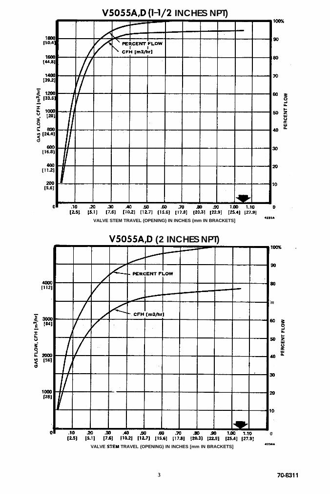
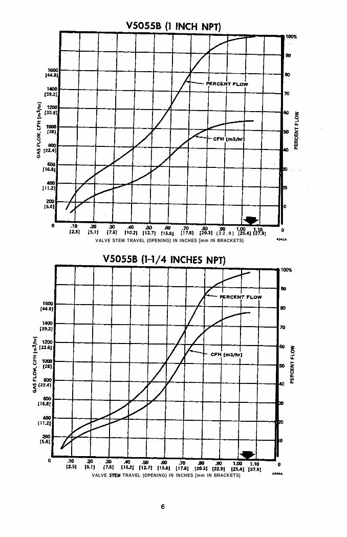
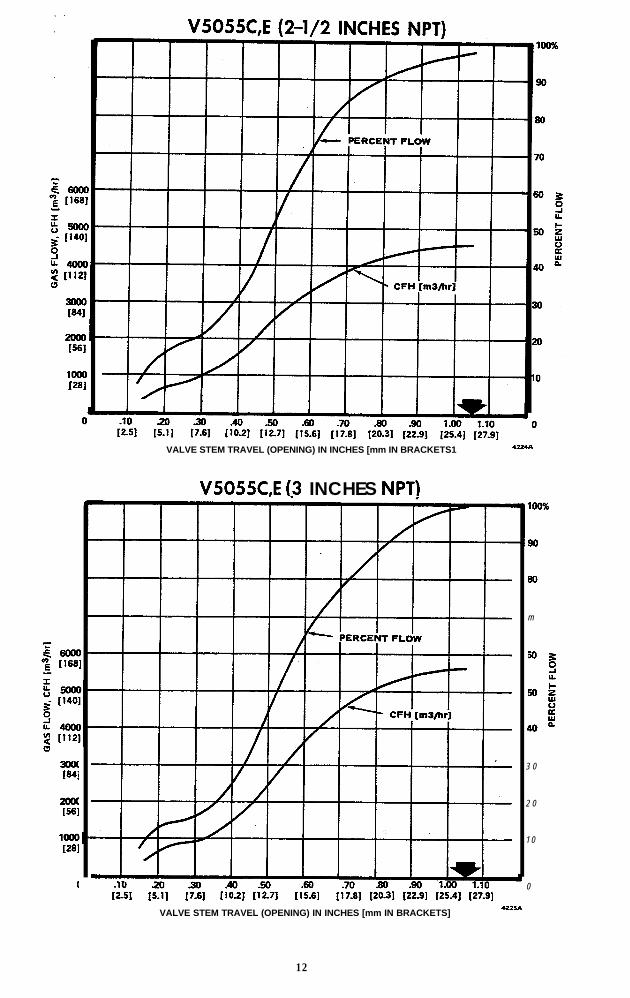
IntroductionThe following curves relate gas flow through the V5055 Industrial Gas Valve to stem travel. These curves showvalve performance under American Gas Association standard conditions:
Specific gravity of gas 0.64
Temperature (Fahrenheit) 60.00 116 Cl
Inlet pressure (inches water) 2.00 [0.5 kPa1
Pressure drop across valve (inches water) 1.00 fO.25 kPa1
The flow is given in both cubic feet per hour (left side of graphs) [cubic metres per hour1 and percent of ratedflow (right side of graphs). Maximum stem travel is 1.05 inches 126.6 mm].
The V5055A Gas Valve is designed for ON-OFF service.
The V5055B Gas Valve has a characterized guide for use with LOW-HIGH or MODULATING actuators, orwith ON-OFF actuators to aid in smooth light off.
The V5055C Gas Valve is designed for ON-OFF service. When used with the proper actuator, it meets FactoryMutual requirements for valve closed indication and Underwriters Laboratories Inc. requirements for valve sealovertravel interlock.
The V5055D Gas Valve is designed for ON-OFF service in high pressure applications.
The V5055E Gas Valve is designed for ON-OFF service in high pressure applications. When used with the properactuator, it meets Factory Mutual requirements for valve closed indication and Underwriters Laboratories inc.requirements for valve seal overtravel interlock.
-V5055A,D (3/4 INCH NPT)
m
12.51 [S.l] [7.6] [10.2] [12.7] [lS.S] [17.8] [20.3] 122.91 [25.4] 127.91
VALVE STEM TRAVEL (OPENING) IN INCHES (mm IN BRACKETS] .?.?.C
1 76B311

‘V5055A,D (1 INCH NPT). .
I
-I
‘!
-A
-3
- 2
- 1
a
VALVE STEM TRAVEL (OPENING) IN INCHES [mm IN BRACKETS] w.31~
80
70
V5055A,D (l-1/4 INCHES NPT)loo?4
90
Bo
70
VALVE STEM TRAVEL (OPENING) IN INCHES [mm IN BRACKETS1.23m
2
V5055A,D (l-1/2 INCHES NPT)
.lO[2.5] [G]
VALVE STEM TRAVEL (OPENING) IN INCHES (mm IN BRACKETS]I
V5055A,D (2 INCHES NPT)
I
1
.lO 0(2S]
m
VALVE SiEM TRAVEL (OPENING) IN INCHES [mm IN BRACKETS].Z4pI
3 7043311

V5055A,D (2-l/2 INCHES NPT)
WI
WI
low1281
(
(2.51 IS.11 [7.6] (10.2] [12.7] j15.61 j17.81 ( 2 0 . 3 1 (22.91 [25.4] ]27_i]
VALVE STEM TRAVEL (OPENING) IN INCHES [mm IN BRACKETS] *ma*
V5055A,D (3 INCHES NPT).
.lO zcl 30[2.5] [5.1] (7.61
VALVE STEM TRAVEL (OPENING) IN INCHES [mm IN BRACKETS] .*szfi
4

V5055A (4 INCHES FLANGED)
6.660’V A CFH [m3/hrl
t1401
4.66611121
1m 1.10 0125.41 127.91
I I I I L I I I 1
n -10 20 30 A0 s.0 .60 .76 .60 .96_._1 2 . 5 1 Iii;1 (7.61 [10.2] [12.7] [IS.61 [17.8) 120.31 I2291
VALVE SfEM TRAVEL (OPENING) IN INCHES [mm IN BRACKETS1.NIB
V5055B (3/4 INCH NPT)
0 .lO[25]
loo%
80
30
70
60 EsLL
50;::
40 L
30
20
10
0
VALVE STEM TRAVEL (OPENING) IN INCHES [mm IN BRACKFIS1 1214
5 70-8311
117.91 (20.3) (22.9) (25.41 [27.9)VALVE STEM TRAVEL (OPENING) IN INCHES [mm IN BRACKETS) .2.,a
VALVE StEM TRAVEL (OPENING) IN INCHES [mm IN BRACKETS) I_
6
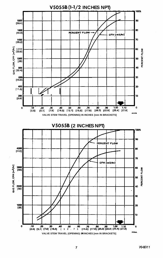
V5055B (l-1/2 INCHES NPT)
g 1200m f33.61.5I4 llloo- 1281
g2800
11’-211 I l/r I2001 I I I I
(S-61
VALVE STEM TRAVEL (OPENING) IN INCHES [mm IN BRACKETS].7.31B
V5055B (2 INCHES NPT)
(251 (5.11 [7.6] (10.21 ( 1 2 . 7 1 (15.61 [17.8] I20.31 122.91 125.41 t27.91
VALVE STEM TRAVEL (OPENING) IN INCHES [mm IN BRACKETS]was4
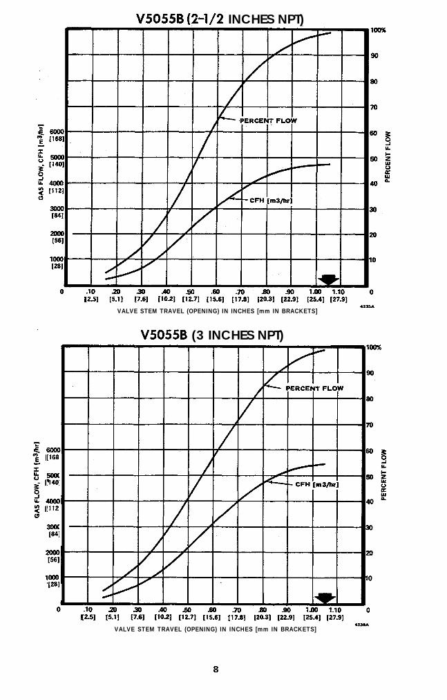
V5055B (2-l/2 INCHES NPT)
2woWI
[168
$
[I12
3ouWI
PI
.lOI2.51
VALVE STEM TRAVEL (OPENING) IN INCHES [mm IN BRACKETS].7.3SA
V5055B (3 INCHES NPT)
.lO[25]
VALVE STEM TRAVEL (OPENING) IN INCHES [mm IN BRACKETS].Z3U
8
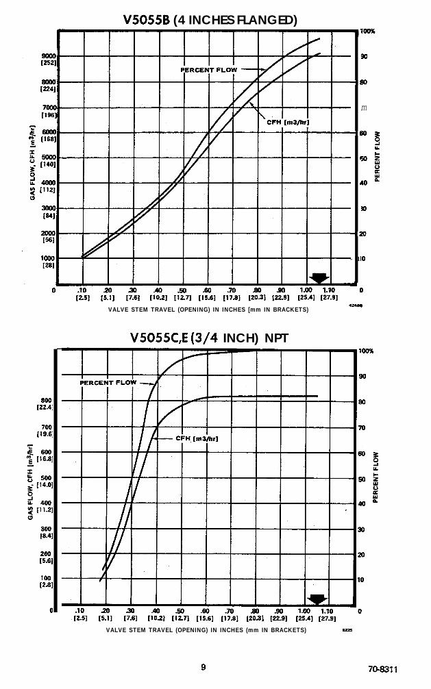
V5055B (4 INCHES FLANGED)
--I
-I
I
,
-:
- 1
dI
m
zo
IO
D
VALVE STEM TRAVEL (OPENING) IN INCHES [mm IN BRACKETS)42.W
V5055C,E (3/4 INCH) NPT
VALVE STEM TRAVEL (OPENING) IN INCHES (mm IN BRACKETS) U2S
70-8311

V5055C,E (1 INCH NPT)
VALVE STEM TRAVEL (OPENING) IN INCHES [mm IN BRACKETS] 423~8
V5055C,E (l-1/4 INCHES NPT)
1
;
0 .lO[2.5] I:, & [i:2, [I%] [l-E] [i:, (2& $1 [:6& $_:,
0
VALVE STEM TRAVEL (OPENING) IN INCHES [mm IN BRACKETS) U.Z?S
10

V5055C,E (l-1/2 INCHES NPT)
2oooWI
10096
90
50
70
60 L3LL
60s%
40 %
30
20
10
0
VALVE STEM TRAVEL (OPENING) IN INCHES [mm IN BRACKETS].ZllB
V5055C,E (2 INCHES NPT)
VALVE STEM TRAVEL (OPENING) IN INCHES [mm IN BRACKETS].%,A
11 704311
WI
lowI281
[1681
3oaWI
2ouWI
WI
1
VALVE STEM TRAVEL (OPENING) IN INCHES [mm IN BRACKETS1 u*u\
V505SC,E (3 INCHES NPTI. .
.lO]2.5] & ]?i] &ii] [I& $S] [i?8] ,2%1 $9, [%I [k;.:]
VALVE STEM TRAVEL (OPENING) IN INCHES [mm IN BRACKETS]47.1sA
60
m
50 L2La.
5050”
z4o”
3 0
2 0
1 0
0
12

V5055C (4 INCHES FLANGED)D’
t
-I
-I
‘!
4
.
-1
dI
VALVE STEM TRAVEL (OPENING) IN INCHES [mm IN BRACKETS].?.ZLB
Capacity Vs. Pressure Drop(for all V5055 Valves)
4
VALVSIZE
1“ii
1‘z
2
2;
3
4
PRESSUREDROP
PSI
15 [103]
10 [70]
5 r351
1 r71
.5 [3.4]
.l 1.71
1m2
I
ki
ii
z
iz
z
z
%0
WC
LooE [25:
Es0,[13
El0:[251,5rr1.3_
cl;[.25
‘.5rj.13
:1[.025
M l M2
- 140,00(f [3900]
,-100,00=[2800]
zi-
?-fi_- 50,000
i!-
[1400]
- 5001 u41
- 2 0 0
V5055 VALVESIZING CHART
OUTLETPRESSURE
(PSI [kPa] GAUGE)! 20 25 10 5 15 [351 [138] [70] [172] [103]
0
SPECIFICGRAVITY
CORRECTION
!.4
-5
-64
- 1 . 0
- 1 . 5
- 2.0
- 2.5
REQUIRED INFORMATIONType of GasSpecific GravityBurner Gas Cfh
(Cfh = Btu/hr f Btu/Ft3)V5055 Inlet (supply) Pressure psi,V5055 Outlet Pressure Required psi.Pressure Drop across valve (valve open)a psi,apressure drop must not exceed l/2 the inlet pressure.
in. wcin. wcin. wc
I V a l v e S i z e inches
13.91 ~2 j Ordering Specification No. V5055 IINSTRUCT1 ONSNOTE: If natural gas (specific gravity 0.64) is used, 3. Draw line 30 from “Outlet Pressure” to
skip steps one and two, and start with step three.1. Draw line 0
“Pressure Drop.” Convert pressure from inch WC to1 from 0.54 on “Specific Gravity psi,if necessa .Correction” to required “Cfh Gas Flow.”
2. Draw line 04. Draw line 46 from “Burner Cfh,” through
2 from “Specific Gravity” of gas used
0intersection of Ml and line @ , to “Valve
through intersection of line 1 and M2 to get Size.” When point falls between two valve sizes,“Burner Cfh.” select the larger one.
148223

1 60-2102—7F.P. • Rev. 10-94 • ©Honeywell Inc. 1994 • Form Number 60-2102—7
V51EButterfly Valve
The V51E Butterfly Valve is a firing rate valveused to provide variable flow control of natural,liquefied petroleum (LP), and manufactured gases.It is also applicable to controlling air flow. The V51EValve is actuated by a firing rate motor mounteddirectly on the valve. The V51E is not applicable asa safety shutoff valve.
The V51E Valve provides high capacity with arelatively constant relationship between flow rateand opening plate angle. The V51E firing ratemotor assembly is especially adaptable to commer-cial and industrial installations that require closecontrol of large gas capacities.
■ Variety of valve sizes, firing rate motors and link-ages. For most modulating applications that do notrequire final shutoff service of firing rate valve.
■ Rugged cast aluminum body provides durability andmaintenance-free operation.
■ Compatible with Modutrol Motor and Q100A or BLinkage, Actionator Motor and Q100C Linkage,and Type 03 Air-O-Motor Pneumatic Actuator andQ524A Linkage.
■ The valve mechanism is equipped with strain releasesprings.
■ Suitable for electric or pneumatic operators with theappropriate linkage.
■ May be used with manufacturers own linkage anddrive motor.
CONTENTS
Specifications ................................................. 2Ordering Information ..................................... 2Installation ..................................................... 5Adjustments and Checkout ............................. 8Maintenance ................................................... 8

60-2102—7 2
V51ESPECIFICATIONS • ORDERING INFORMATION
SpecificationsIMPORTANT: The specifications in this publication do not
include normal manufacturing tolerances. Therefore,units may not exactly match the listed specifications.Also, products are tested and calibrated under closelycontrolled conditions, and some minor differences inperformance can be expected if those conditions arechanged.
MODEL: V51E Butterfly Valve.
TYPES OF GASES: Natural, liquefied petroleum (LP), manu-factured, and air.
FLOW CAPACITIES: See Fig. 1.
SIZES: 1-1/2, 2, 2-1/2, 3, and 4 inches.
PATTERN: Straight-through.
BODY MATERIAL: Aluminum.
MAXIMUM INLET PRESSURE: 5 psig. See Fig. 3.
AMBIENT TEMPERATURE RANGE: 32° F to 140° F[0° C to 60° C].
MAXIMUM FLUID TEMPERATURE: 140° F.
DIMENSIONS: See Fig. 2.
ACCESSORIES:16350 Actuating Lever Pin.16351 Operating Arm Relief Pin.22355 Stop Screw Locking Nuts (two required).49084 Adjusting Arm.49085B Strain Release Assembly for Q100A.
49087 Spring.49090 Yoke Pin for mounting actuating arm to linkage.80897BC Stop Screws for stop bracket (two required).104266 Q100 Actuator Arm.127411 Bracket for 1-1/2 in. V51E.127413 Bracket for 2 in. V51E.
APPROVALS:Underwriters Laboratories Inc.: File No. MH5968, Vol. I,
Section 1, Guide No. MHKZ.
Fig. 1—V51E Valves Flow Capacities.
Ordering InformationWhen purchasing replacement and modernization products from your TRADELINE® wholesaler or your distributor, refer to theTRADELINE® catalog or price sheets for complete ordering number, or specify:
1. Valve model.2. Valve size (1-1/2, 2, 2-1/2, 3, 4 inches)3. Accessories.4. Order motor and linkage separately. Refer to applicable Specifications.
If you have additional questions, need further information, or would like to comment on our products or services, please write or phone:1. Your local Honeywell Home and Building Control Sales Office (check white pages of phone directory).2. Home and Building Control Customer Logistics
Honeywell Inc.,1885 Douglas Drive NorthMinneapolis, Minnesota 55422 (612) 951-1000
In Canada—Honeywell Limited/ Honeywell Limitée, 740 Ellesmere Road, Scarborough, Ontario M1P 2V9. International Sales andService Offices in all principal cities of the world. Manufacturing in Australia, Canada, Finland, France, Germany, Japan, Mexico,Netherlands, Spain, Taiwan, United Kingdom, U.S.A.
CA
PA
CIT
Y, I
N 1
,000
's O
F C
F/H
[m
3 /h
]
40[1.412]
35[1.253]
30[1.059]
25[.880]
20[.706]
15[.529]
10[.353]
5[.176]
OPENING ANGLE
10° 20° 30° 40° 50° 60° 70°
M9530
CHART BASED ON GAS OF 0.64 SP. GR. AND AT 1 in. [25 mm] WC PRESSURE DROP ACROSS VALVE
4 in
. [10
2 m
m]
3 in. [7
6 mm]
2 1/2 in. [64 mm]
1 1/2 in. [38 mm]2 in. [51 mm]
3 60-2102—7
V51ESPECIFICATIONS
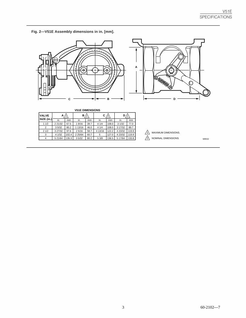
Fig. 2—V51E Assembly dimensions in in. [mm].
VALVESIZE (in.)
1 1/2
2
2 1/2
3
4
2 21/32
3 5/32
3 27/32
4 1/32
5 21/64
67.5
80.2
97.6
102.4
135.3
A
A
1
in. mm
1 9/16
1 13/16
2 5/16
2 25/64
3 5/32
39.7
46.0
58.7
60.7
80.2
B
B
in. mm
4 1/4
4 1/4
4 13/16
5
5 3/8
108.0
108.0
122.2
127.0
136.5
C
C
in. mm
3 1/32
3 17/32
4 23/32
4 23/32
5 17/64
77.0
89.7
119.9
119.9
133.8
D
D
in. mm
M9532
1 2 1
1 MAXIMUM DIMENSIONS.
NOMINAL DIMENSIONS.2
V51E DIMENSIONS

60-2102—7 4
Fig. 3—Pressure drop versus capacity. Maximum opening angles shown are used as trial settings whenadjusting valves for high fire.
M9527
100
1001 2 3 4 5 6 7 8 9 1 2 3 4 5 6 7 8 9 1 2 3 4 5 6 7 8 9 1
90807060
50
40
30
20
109876
5
4
3
2
10.90.80.70.6
0.5
0.4
0.3
0.2
0.1
1000 10000 100000
CAPACITY, IN cf/h WITH 0.64 SP. GR. GAS [1 cf/h = 0.0283 m3/hr]
PR
ES
SU
RE
DR
OP
, IN
CH
ES
WC
[1
in. w
c =
0.25
kP
a]
2 in. 3 in. 4 in.1 in.12
MAXIMUM OPENINGANGLE
30° 40° 50° 30° 50°
45° 57°55°45°35°
45°
40° 50° 60° 40° 50° 60°
55° 45° 55°
V51ESPECIFICATIONS
5 60-2102—7
InstallationWHEN INSTALLING THIS PRODUCT…
1. Read these instructions carefully. Failure to followthem could damage the product or cause a hazardouscondition.
2. Check the ratings given in the instructions and on theproduct to make sure the product is suitable for yourapplication.
3. Installer must be a trained, experienced, flame safe-guard control technician.
4. After installation is complete, check out product op-eration as provided in these instructions.
CAUTION1. Turn off gas supply before starting installation.2. Disconnect power supply before beginning in-
stallation to prevent electrical shock and equip-ment damage.
MOUNTINGElectric motorized valves of this type should not be
installed in poorly ventilated pits or confined spaces forcontrol of combustible gas flow. The valve body may beinstalled in any position provided the motor shaft is horizon-tal. Allow sufficient clearance for assembling the motor andlinkage, and for general servicing. See Fig. 2 for installationdimensions.
PIPINGThe valve body may be piped either by screwing directly
to the pipe or by using close nipples and companion flanges.The pipes must be in exact alignment to avoid distorting thevalve body. Ream and clean pipes carefully, and apply pipedope to the male threads only. Leave the first two threads freeof dope.
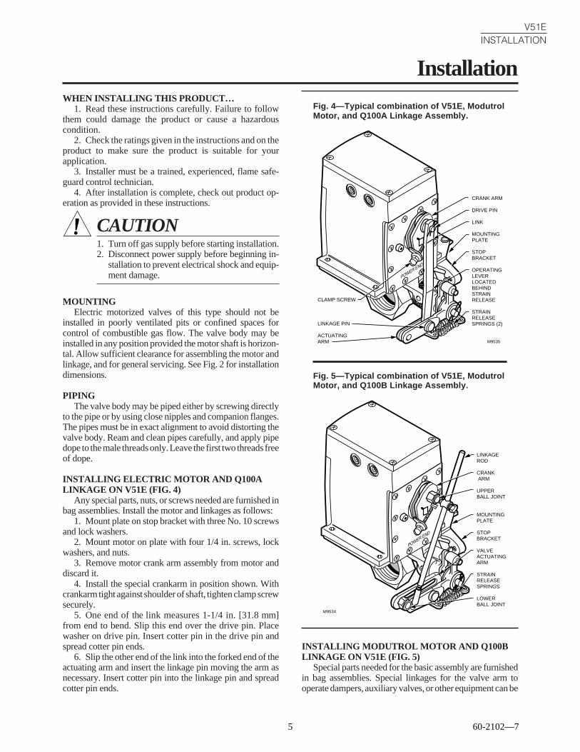
INSTALLING ELECTRIC MOTOR AND Q100ALINKAGE ON V51E (FIG. 4)
Any special parts, nuts, or screws needed are furnished inbag assemblies. Install the motor and linkages as follows:
1. Mount plate on stop bracket with three No. 10 screwsand lock washers.
2. Mount motor on plate with four 1/4 in. screws, lockwashers, and nuts.
3. Remove motor crank arm assembly from motor anddiscard it.
4. Install the special crankarm in position shown. Withcrankarm tight against shoulder of shaft, tighten clamp screwsecurely.
5. One end of the link measures 1-1/4 in. [31.8 mm]from end to bend. Slip this end over the drive pin. Placewasher on drive pin. Insert cotter pin in the drive pin andspread cotter pin ends.
6. Slip the other end of the link into the forked end of theactuating arm and insert the linkage pin moving the arm asnecessary. Insert cotter pin into the linkage pin and spreadcotter pin ends.
Fig. 4—Typical combination of V51E, ModutrolMotor, and Q100A Linkage Assembly.
V51EINSTALLATION
CRANK ARM
DRIVE PIN
LINK
MOUNTINGPLATE
STOPBRACKET OPERATINGLEVERLOCATEDBEHINDSTRAINRELEASE
STRAINRELEASESPRINGS (2)
CLAMP SCREW
LINKAGE PIN
ACTUATING ARM M9535
Fig. 5—Typical combination of V51E, ModutrolMotor, and Q100B Linkage Assembly.
M9534
LINKAGE ROD
CRANK ARM
UPPER BALL JOINT
MOUNTING PLATE
STOP BRACKET
VALVE ACTUATING ARM
STRAIN RELEASE SPRINGS
LOWER BALL JOINT
INSTALLING MODUTROL MOTOR AND Q100BLINKAGE ON V51E (FIG. 5)
Special parts needed for the basic assembly are furnishedin bag assemblies. Special linkages for the valve arm tooperate dampers, auxiliary valves, or other equipment can be
60-2102—7 6
V51EINSTALLATION
provided by the burner manufacturer or installer. Install themotor and linkage on the valve as follows:
1. Mount plate on stop bracket with three No. 10 screwsand lock washers.
2. Mount motor on plate with 1/4 in. screws, lock wash-ers, and nuts.
3. Make sure the motor is in the closed position (theposition assumed when red and white terminals on motor areshorted together). Install motor crank arm and tighten clampscrew securely.
4. Install valve actuating arm as shown in Fig. 5, andadjust as desired.
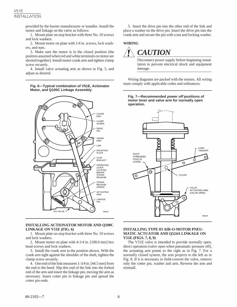
Fig. 6—Typical combination of V51E, ActionatorMotor, and Q100C Linkage Assembly.
5. Insert the drive pin into the other end of the link andplace a washer on the drive pin. Insert the drive pin into thecrank arm and secure the pin with a nut and locking washer.
WIRING
CAUTIONDisconnect power supply before beginning instal-lation to prevent electrical shock and equipmentdamage.
Wiring diagrams are packed with the motors. All wiringmust comply with applicable codes and ordinances.
Fig. 7—Recommended power off positions ofmotor lever and valve arm for normally openoperation.
M9533
COVEREND
CLAMPSCREW
DRIVEPIN
CRANKARM
LINK
MOUNTINGPLATE
STOPBRACKET
OPERATINGLEVERLOCATEDBEHINDSTRAINRELEASE
STRAINRELEASESPRING
ACTUATINGARM
LINKAGEPIN
V51 VALVE
INSTALLING ACTIONATOR MOTOR AND Q100CLINKAGE ON V51E (FIG. 6)
1. Mount plate on stop bracket with three No. 10 screwsand lock washers.
2. Mount motor on plate with 4-1/4 in. [108.0 mm] hexhead screws and lock washers.
3. Install the crank arm in the position shown. With thecrank arm tight against the shoulder of the shaft, tighten theclamp screw securely.
4. One end of the link measures 1-3/4 in. [44.5 mm] fromthe end to the bend. Slip this end of the link into the forkedend of the arm and insert the linkage pin, moving the arm asnecessary. Insert cotter pin in linkage pin and spread thecotter pin ends.
M9529
LOAD TAKEOFF
CLEVIS
VALVE ACTUATING ARM (VALVE OPEN)
PIVOT(THREADED HOLE IN LEVER)
INSTALLING TYPE 03 AIR-O-MOTOR PNEU-MATIC ACTUATOR AND Q524A LINKAGE ONV51E (FIGS. 7, 8, 9)
The V51E valve is intended to provide normally open,direct operation (valve open when pneumatic pressure off),the actuating arm points to the right as in Fig. 7. For anormally closed system, the arm projects to the left as inFig. 8. If it is necessary to field-convert the valve, removeonly the cotter pin, washer and arm. Reverse the arm andreinstall.

7 60-2102—7
Fig. 8—Recommended arrangement fornormally closed operation.
V51EINSTALLATION
5. Use the four large cap screws supplied with the link-age assembly to secure the motor to the adapter plate.
6. Add the ball joint assembly and push rod as shown inFig. 10.
Fig. 9—Relationship of parts in V51E.
M9528
LOAD TAKEOFF
CLEVIS
VALVE ACTUATING ARM (VALVE CLOSED)
PIVOT(THREADED HOLE IN LEVER)
1. Remove the four round-head machine screws andwashers holding the stop bracket to the valve hex at each end.Do not remove the stop bracket
2. Position the adapter plate over the stop bracket so thatthe adapter plate holes match the stop bracket holes.
3. Insert the flat head screws supplied with the linkageassembly through plate, spacers, and stop bracket and intoeach hex. Tighten securely. The spacers prevent contact ofadapter plate and stop bracket. See Fig. 9.
4. Mount the lever arm (13-3/4 in. [349.3 mm]) suppliedwith the motor so the load takeoff holes will be at the sameend of the valve as the valve actuating arm.
NOTE: Both motor lever and valve arm could be installed180 degrees from the positions shown in Figs. 7 and 8, ifmore convenient. Use bushing hole at the clevis.
Fig. 10—Typical combination of V51E, Air-O-Motor Pneumatic Actuator, and Q524 Linkage.
UPPER BALL JOINT
1 NUT EACH SIDE OF LEVER
BALL JOINTASSEMBLY
PUSH ROD
LOWER BALL JOINT
M9583
FLAT HEAD SCREWS (4) ADAPTER PLATE
SPACERS (4)
STOPBRACKET
VALVEACTUATING ARM
SUPPLIED WITH LINKAGE.1 M9536
1

V51EADJUSTMENTS AND CHECKOUT • MAINTENANCE
Adjustments and CheckoutMODUTROL MOTOR WITH Q100A LINKAGEAND V51E (FIG. 4)Minimum Flow Adjustment
Using the motor, drive the valve to the closed position.Loosen the lock nut on the stop screw. Turn this screw inagainst the operating lever until the desired minimum flowposition is obtained. If fully closed is the minimum positiondesired, back the screw out until its threaded end is flushwith the stop bracket. Tighten the lock nut.
Maximum Flow AdjustmentWith motor in closed position, loosen the lock nut on the
stop screw. Turn this screw in against the operating leveruntil desired minimum flow position is obtained. If fullyclosed is the minimum position desired, back the screw outuntil it ends flush with the stop bracket. Tighten the lock nut.
MODUTROL MOTOR WITH Q100B LINKAGEAND V51E (FIG. 5)
1. Loosen setscrews in upper ball joint to allow linkagerod to slide freely. Loosen lower ball joint so it slides freelyin the actuating arm slot
2. Short the motor terminals red to white to drive themotor closed.
3. Hold valve butterfly open at the desired low-fire posi-tion and tighten the lower ball joint hand tight against theouter end of the actuating arm slot. Tighten screw in theupper ball joint enough to provide some friction on the rod,but not enough to prevent it from sliding if the valve reachesits stop
4. Short the motor terminals red to blue. As motor drivesopen, note the valve travel. Reset the lower ball joint to theproper high-fire valve position.
NOTE: When the lower ball joint is moved, the upper balljoint usually must be readjusted if the valve is to keep thesame low-fire position
ACTIONATOR MOTOR WITH Q100C LINKAGEAND V51E (FIG. 6)Minimum Flow Adjustments
Using the motor, drive valve to the open position. Loosenthe lock nut on the stop screw. Turn this screw in against theoperating lever until the desired maximum flow adjustmentis obtained. If fully open is the maximum position desired,back out the screw until its threaded end is flush with the stopbracket. Tighten lock nut.
Maximum Flow AdjustmentUsing the motor, drive valve to the open position. Loosen
the lock nut on the stop screw. Turn this screw in against theoperating lever until the desired maximum flow adjustmentis obtained. If fully open is the maximum position desired,back out the screw until its threaded end is flush with the stopbracket. Tighten lock nut.
CHECKOUTCycle the burner twice through high-fire and low-fire
while observing the actuating arm for smooth operation andwatching the burner flame level for proper regulation of gasor air. Make certain the actuator arm does not hang up whilethe drive motor is in operation.
For detailed operation of drive motor and linkage, refer toapplicable instructions furnished with the device.
MaintenancePACKING THE VALVE
No field maintenance is required.
LUBRICATIONPlace a few drops of SAE20 or heavier oil on linkage
bearings whenever required. The motor needs no lubricationin the field.
MECHANICAL LINKAGESMechanical linkages may be devised to operate dampers
or other valves in unison or sequence with this assembly. Inno application should the combined load of the valve,damper, and linkage exceed the rated load limit of the motorfor its timing. See applicable motor instructions.
Home and Building Control Home and Building Control Helping You Control Your WorldHoneywell Inc. Honeywell Limited—Honeywell Limitée1985 Douglas Drive North 740 Ellesmere RoadGolden Valley, MN 55422 Scarborough, Ontario
M1P 2V9
Printed in U.S.A.
QUALITY IS KEY
® U.S. Registered TrademarkCopyright © 1999 Honeywell Inc. • All Rights Reserved
INSTALLATION INSTRUCTIONS
66-1099
Integrated Valve Train
APPLICATIONThese Integrated Gas Valve Train component installationinstructions are for small valves (3/4 in. to 2 in.) and largevalves (2 in. to 3 in.) are identical except where noted.
INSTALLATION
When Installing this product...1. Read these instructions carefully. Failure to follow them
could damage the product or cause a hazardouscondition.
2. Check ratings given in these instructions and on theproduct to make sure the product is suitable for yourapplication.
3. Make sure the installer is a trained, experienced servicetechnician.
4. Use these instructions to check out product operationafter installation.
WARNINGFire or Explosion Hazard.Can cause property damage, serious injury ordeath.Perform the safety shutdown test any time work isdone on a gas system.Make sure gas is turned off before starting installation.
Bolt Torque SpecificationsTorque specifications for the two bolt sizes are:• 3/8 in. 16 bolts: 13 lb-ft.• 1/2 in.-13 bolts: 25 lb-ft.
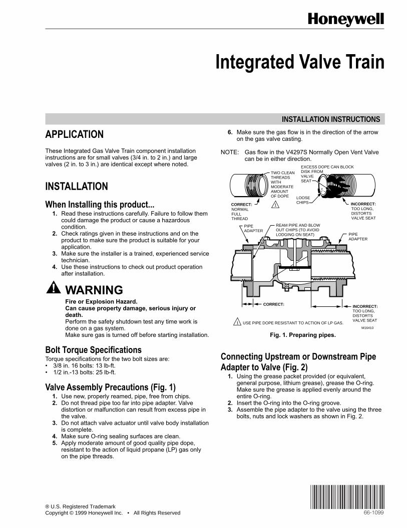
Valve Assembly Precautions (Fig. 1)1. Use new, properly reamed, pipe, free from chips.2. Do not thread pipe too far into pipe adapter. Valve
distortion or malfunction can result from excess pipe inthe valve.
3. Do not attach valve actuator until valve body installationis complete.
4. Make sure O-ring sealing surfaces are clean.5. Apply moderate amount of good quality pipe dope,
resistant to the action of liquid propane (LP) gas onlyon the pipe threads.
6. Make sure the gas flow is in the direction of the arrowon the gas valve casting.
NOTE: Gas flow in the V4297S Normally Open Vent Valvecan be in either direction.
Fig. 1. Preparing pipes.
Connecting Upstream or Downstream PipeAdapter to Valve (Fig. 2)
1. Using the grease packet provided (or equivalent,general purpose, lithium grease), grease the O-ring.Make sure the grease is applied evenly around theentire O-ring.
2. Insert the O-ring into the O-ring groove.3. Assemble the pipe adapter to the valve using the three
bolts, nuts and lock washers as shown in Fig. 2.
INCORRECT:
CORRECT:
TWO CLEANTHREADS WITHMODERATEAMOUNTOF DOPE
EXCESS DOPE CAN BLOCKDISK FROM VALVE SEAT
LOOSE CHIPSCORRECT:
NORMAL FULL THREAD
REAM PIPE AND BLOW OUT CHIPS (TO AVOIDLODGING ON SEAT)
TOO LONG, DISTORTS VALVE SEAT
TOO LONG,DISTORTS VALVE SEAT
M164101
1
USE PIPE DOPE RESISTANT TO ACTION OF LP GAS.
INCORRECT:
PIPEADAPTER
PIPEADAPTER
2
INTEGRATED VALVE TRAIN
66-1099
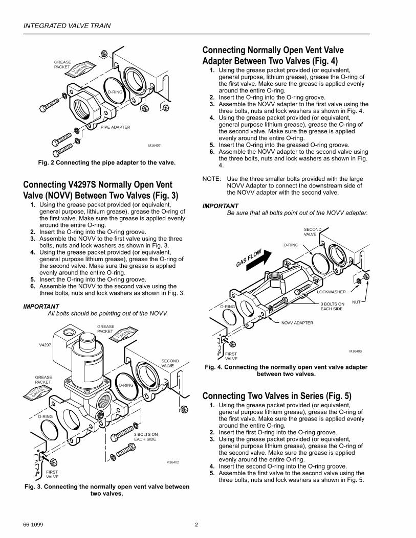
Fig. 2 Connecting the pipe adapter to the valve.
Connecting V4297S Normally Open VentValve (NOVV) Between Two Valves (Fig. 3)
1. Using the grease packet provided (or equivalent,general purpose, lithium grease), grease the O-ring ofthe first valve. Make sure the grease is applied evenlyaround the entire O-ring.
2. Insert the O-ring into the O-ring groove.3. Assemble the NOVV to the first valve using the three
bolts, nuts and lock washers as shown in Fig. 3.4. Using the grease packet provided (or equivalent,
general purpose lithium grease), grease the O-ring ofthe second valve. Make sure the grease is appliedevenly around the entire O-ring.
5. Insert the O-ring into the O-ring groove.6. Assemble the NOVV to the second valve using the
three bolts, nuts and lock washers as shown in Fig. 3.
IMPORTANTAll bolts should be pointing out of the NOVV.
Fig. 3. Connecting the normally open vent valve betweentwo valves.
Connecting Normally Open Vent ValveAdapter Between Two Valves (Fig. 4)
1. Using the grease packet provided (or equivalent,general purpose, lithium grease), grease the O-ring ofthe first valve. Make sure the grease is applied evenlyaround the entire O-ring.
2. Insert the O-ring into the O-ring groove.3. Assemble the NOVV adapter to the first valve using the
three bolts, nuts and lock washers as shown in Fig. 4.4. Using the grease packet provided (or equivalent,
general purpose lithium grease), grease the O-ring ofthe second valve. Make sure the grease is appliedevenly around the entire O-ring.
5. Insert the O-ring into the greased O-ring groove.6. Assemble the NOVV adapter to the second valve using
the three bolts, nuts and lock washers as shown in Fig.4.
NOTE: Use the three smaller bolts provided with the largeNOVV Adapter to connect the downstream side ofthe NOVV adapter with the second valve.
IMPORTANTBe sure that all bolts point out of the NOVV adapter.
GREASE PACKET
O-RING
PIPE ADAPTER
M16407
O-RING
O-RING
M16402
GREASE PACKET
GREASE PACKET
FIRSTVALVE
SECONDVALVE
V4297
3 BOLTS ON EACH SIDE
O-RING
O-RING
M16403
SECONDVALVE
FIRSTVALVE
3 BOLTS ON EACH SIDE
NOVV ADAPTER
LOCKWASHER
NUT
GAS FLOW
Fig. 4. Connecting the normally open vent valve adapterbetween two valves.
Connecting Two Valves in Series (Fig. 5)1. Using the grease packet provided (or equivalent,
general purpose lithium grease), grease the O-ring ofthe first valve. Make sure the grease is applied evenlyaround the entire O-ring.
2. Insert the first O-ring into the O-ring groove.3. Using the grease packet provided (or equivalent,
general purpose lithium grease), grease the O-ring ofthe second valve. Make sure the grease is appliedevenly around the entire O-ring.
4. Insert the second O-ring into the O-ring groove.5. Assemble the first valve to the second valve using the
three bolts, nuts and lock washers as shown in Fig. 5.

INTEGRATED VALVE TRAIN
3 66-1099
IMPORTANTPoint the top two bolts upstream and the third boltdownstream when connecting two valves in series.
Connecting a C6097 Pressure Switch to aValve (Fig. 6)
1. Remove the 1/4 in. (6 mm) NPT plug from the side ofthe valve.
2. Remove the label holding the O-ring in place on theC6097 and make sure the O-ring seal is in place.
3. Remove the C6097 Cover by removing the coverscrews.
4. Mount the C6097 Pressure Switch on the valve usingthe two screws provided.
5. Replace the C6097 Cover.
Fig. 5. Connecting two valves in series.
O-RINGS
M16409
SECONDVALVE
FIRSTVALVE
GAS FLOW
M16408
VALVE
REMOVE PLUG(1/4 IN. SOCKET HEAD)
C6097BODY
C6097COVER
Fig. 6. Connecting C6097 Pressure Switch to Valve.
Completing the Assembly (Fig. 7):1. Assemble the upstream and downstream pipes to the
valve train.2. Apply a parallel jaw wrench only to the pipe adapter flat
next to the pipe being inserted (Fig. 7). A wrenchapplied to the valve body itself, or to the end farthestfrom the pipe being inserted, can distort the casting,causing a malfunction. Do not use the valve as a lever.
3. Make sure the gas flow is in the same direction as thearrow on the valve body.
4. Paint the pipe adapters and valve train componentswith a rich soap and water solution to check for bubblesthat indicate a gas leak at the pipe adapter and valvemating surfaces.
5. Make sure the power supply is disconnected from thepowered components. Mount the actuators on the valvebodies and complete the electrical and linkageconnections by following the instructions packed withthe actuators and solenoid valves.
CORRECT:VISE GRIPS END NEXT TO PIPEBEING INSERTED
CORRECT:WRENCH CORRECTLYAPPLIED NEXT TO PIPE BEING INSERTED INCORRECT:
WRENCH APPLIED HERE STRAINS VALVE BODY
M11684
Fig. 7. Completing the valve train.

4
INTEGRATED VALVE TRAIN
66-109966-1099 G. R. 4-99
Home and Building ControlHoneywell Limited-Honeywell Limitée155 Gordon Baker RoadNorth York, OntarioM2H 3N7
Home and Building ControlHoneywell Inc.Honeywell PlazaP.O. Box 524Minneapolis MN 55408-0524
Printed in U.S.A. on recycled paper containing at least 10% post-consumer paper fibers. www.honeywell.com