Embed Size (px)
Citation preview

(/)"0CctJ
~.J::CDZID
-£.£"0IDCitIDU
~C
:;o-£.§IDClCctJ
.J::U
.Bt5IDE:l
(f)
APPLICATION
The gas pressure switch C6097A is used to detect thepressure of city gas, natural gas, LP gas or air etc.
When the gas pressure changes, the diaphragm of thepressure receiving part detects it and operates the (SPOT)switch to ON/OFF control of the external electrical circuit.
These switches are widely used to detect the upper limit orlower limit pressure of gas or air to be supplied to a gasburner, or to detect the clogging of the interlock filter of aburner blower.
SPECIFICATIONS
Product rangeThere are two versions available: stand alone and flangemounted, see table 1. and 2.
Table 1. C6097A flanged mounted models
Model Operating Nominal Maximumpressure operating working
range differential pressure(mbar) (mbar) (mbar)
C6097A2200 2.5 ... 50 0.6 300
C6097A2300 30 ... 150 2.8 500
C6097A2400 100 ... 500 7.0 600
Honeywell
UNIVERSAL GAS VALVES
C6097AGAS PRESSURE SWITCHES
INSTRUCTION SHEET
Table 2. C6097A stand alone models
Model Operating Nominal Maximumpressure operating working
range differential pressure(mbar) (mbar) (mbar)
C6097A2110 1.0 ... 10 0.4 200
C6097A2210 2.5 ... 50 0.6 300
C6097A2310 30 ... 150 2.8 500
C6097A2410 100 ... 500 7.0 600NOTE: The operating differential IS the difference between
the upper and lower operating pressures at one setpoint.
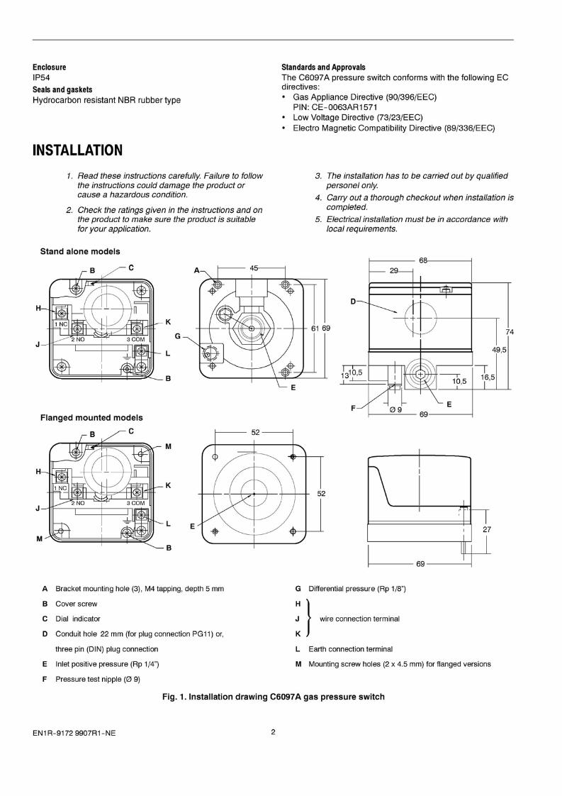
DimensionsSee Figure 1.ConnectionInlet positive pressure Rp1/4" internal pipe thread (2 x).Differential pressure Rp 1/8" internal pipe thread.All connections according to ISO 7-1Set point accuracy
15% of the full scale (when pressure is increased)NOTE: The knob readings are approximations of the actual
settings.
Torsion and bending stressPipe connections meet group 2, according to EN161requirements.Contact ratingsResistive load: 250 Vac, 5AInductive load: 250 Vac, 3A (power factor 0.6)Minimum contact current and voltage: 50 mA, 24 VacMaterial of pressure receiving partsNBR single diaphragmMaterial of housingAluminium die-castMaterial of casePolybutylene terephthalateMaterial of coverPolycarbonateAmbient temperature range-15 ... 60 CRelative humidity: max. 90% at 40 C (non-condensing)Sensed medium temperature range-15 ... 80 CElectrical connectionPlug connection according to PG11 or three pin plugconnector ("DIN plug")Protection against electrical shock: class IWire connection terminalsM3.5 screw terminals, including earth connection
EN1 R-9172 9907R1-NE
EnclosureIP54
Seals and gasketsHydrocarbon resistant NBR rubber type
Standards and ApprovalsThe C6097A pressure switch conforms with the following ECdirectives:• Gas Appliance Directive (90/396/EEC)
PIN: CE-0063AR1571• Low Voltage Directive (73/23/EEC)• Electro Magnetic Compatibility Directive (89/336/EEC)
INSTALLATION
1. Read these instructions carefully. Failure to followthe instructions could damage the product orcause a hazardous condition.
2. Check the ratings given in the instructions and onthe product to make sure the product is suitablefor your application.
3. The installation has to be carried out by qualifiedpersonel only.
4. Carry out a thorough checkout when installation iscompleted.
5. Electrical installation must be in accordance withlocal requirements.
Stand alone models
c
49,5
74
EF
D
E=j68
61 69G
B
K
H
J --tlF---,-------t--,--,,_
----- 69 -------I
52
1----=---.::-- 69-------1
1---- 52 ------1
E
B
K
Flanged mounted models
C
J --ttf---,-------t--,--,,_
H
A Bracket mounting hole (3), M4 tapping, depth 5 mm
B Cover screw
C Dial indicator
D Conduit hole 22 mm (for plug connection PG11) or,
three pin (DIN) plug connection
E Inlet positive pressure (Rp 1/4")
F Pressure test nipple (0 9)
G Differential pressure (Rp 1/8")
~} w;" ooo"d;oo ",m;,,'
L Earth connection terminal
M Mounting screw holes (2 x 4.5 mm) for flanged versions
Fig. 1. Installation drawing C6097A gas pressure switch
EN1R-91729907R1-NE 2

NO } load sld,
NC
3 voltage side
CaM
~ earth connection• Disconnect power supply to the pressure switchbefore beginning the installation to preventelectrical shock and damage to the equipment.
• Turn off gas supply before installation.
Mounting and orientationIn vertical, or horizontal plane with the setting dial facingupwards. Make sure that dirt or humidity does not get into theconnection open for ventilation (G in Figure. 1.).
A WARNING
Fig. 2. C6058 connection diagram
Fig. 3. C6097958 connection diagram with DIN plug
Working principleOn pressure rise, terminals between CaM and NO are closed.
On pressure fall, terminals between CaM and NC are closed.
2
3
blue
brown
NC
CaM
'---------{ 3 1--1-----,------'black
• Do not remove the seal over the pressure inlets,until ready to connect piping.
Connecting positive pressure inlet (stand alone)1. Take care that dirt does not enter the pressure switch
during handling.
2. Remove the dust seal from the positive pressure inlet.
3. Apply a moderate amount of good quality compound tothe pipe for fitting only, leaving the end thread bare,PTFE tape tape may be used as an alternative.
4. Use a sound tapper fitting with thread according toISO 7-1 (8S21 , DIN 2999) or new, properly reamedpipe, free from swarf.
5. Screw the pressure switch onto the pipe, using thewrench boss incorporated in the housing.
6. Complete the electrical connections as instructed in theElectrical connections section.
Connecting positive pressure inlet (flange mounted)1. Take care that dirt does not enter the pressure switch
during handling.
2. Remove the dust seal from the positive pressure inlet.
3. Place the a-ring. If necessary grease it slightly to keepit in place.
4. Mount the pressure switch on the valve body and screwit tightly with the two M4 mounting screws.
5. Complete the electrical connections as instructed in theElectrical connections section.
A WARNINGTightness test after installation
• Spray a moderate amount of of good quality leakdetection spray on all pipe connections.
• Start the application and check for bubbles. If aleak is detected in a pipe connection, remake thejoint.
ADJUSTMENT AND CHECKOUT
Electrical connection
A WARNING• Switch off power supply before making electrical
connections.
A WARNING• The adjustment and checkout has to be carried out
by qualified personnel only.
• Terminals are accessible, no protection againstelectrical shock.
• Take care that the wiring is in accordance with localregulations.
Use lead wire that can withstand 105 QC ambient.
The electrical ON/OFF operator is provided with a terminalblock for electrical connections.
WiringFollow the instructions supplied by the appliancemanufacturer. Refer to Figure 2. and 3. Connection diagramC6097A.
Pressure set point adjustment(tolerance ± 15 % over total scale)
NOTE: The knob readings are approximations of the actualsettings.
1. Remove the cover of the pressure switch.
2. Turn the dial clockwise to increase orcounter-clockwise to decrease the pressure set point.
3. Replace the cover.
3 EN1R-91729907R1-NE

Accurate pressure set point adjustment(stand alone only)(tolerance <3% over total scale)
1. Remove the screw from the test nipple inlet.2. Connect the tube of the pressure measurement device
to the nipple (Fig. 1. F).3. Remove the cover of the pressure switch.4. Slowly release pressure of the main gas supply line until
the desired value is reached.5. Turn dial slowly until contact 1-3 opens and contact
2-3 closes.6. Replace the cover.7. Disconnect the pressure measurement device and
replace the screw.
Checkout
Checking cut-off pressureAfter the installation is completed, continue with the followingprocedures:
1. Slowly close manual main valve with the burner inoperation. Shut down should occur when the pressuredrops below the set point and the alarm (if connected)should be energized.
2. Re open the manual main valve. The pressure shouldrise and exceed the set point value, the burner shouldstart up and the alarm turn off after the reset button isdepressed.
HoneywellCombustion Controts Center EuropeHoneywell BVPhileas Foggstraat 77821 AJEmmen, The NetherlandsTel: +31 (0) 591695911Fax: +31 (0) 591695200EN1R-91729907R1-NE
Honeywell UGV S.r.l.Via Ferrero, 1610090 Cascine- Vica Rivoli (TO)Turin, ItalyTel: +39 (11) 957 8311Fax: +39 (11) 957 8322
4