Embed Size (px)
Citation preview
3-20-41 Higashimotomachi, Kokubunji, Tokyo 185-8533, Japan
https://www.rion.co.jp/english/
INSTRUCTION MANUAL
Two-Channel Charge Amplifi er
UV-16

i
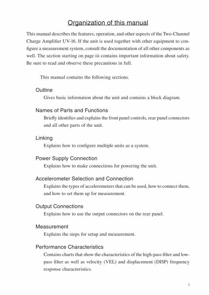
Organization of this manual
This manual describes the features, operation, and other aspects of the Two-Channel
Charge Amplifi er UV-16. If the unit is used together with other equipment to con-
fi gure a measurement system, consult the documentation of all other components as
well. The section starting on page iii contains important information about safety.
Be sure to read and observe these precautions in full.
This manual contains the following sections.
Outline
Gives basic information about the unit and contains a block diagram.
Names of Parts and Functions
Briefl y identifi es and explains the front panel controls, rear panel connectors
and all other parts of the unit.
Linking
Explains how to confi gure multiple units as a system.
Power Supply Connection
Explains how to make connections for powering the unit.
Accelerometer Selection and Connection
Explains the types of accelerometers that can be used, how to connect them,
and how to set them up for measurement.
Output Connections
Explains how to use the output connectors on the rear panel.
Measurement
Explains the steps for setup and measurement.
Performance Characteristics
Contains charts that show the characteristics of the high-pass fi lter and low-
pass fi lter as well as velocity (VEL) and displacement (DISP) frequency
response characteristics.
ii
* Company names and product names mentioned in this manual are usually
trademarks or registered trademarks of their respective owners.
Specifi cations
Lists the technical specifi cations of the unit.
Reference Material
Provides representative data for accelerometer inherent noise. Maintenance
parts are also listed in this section.
iii
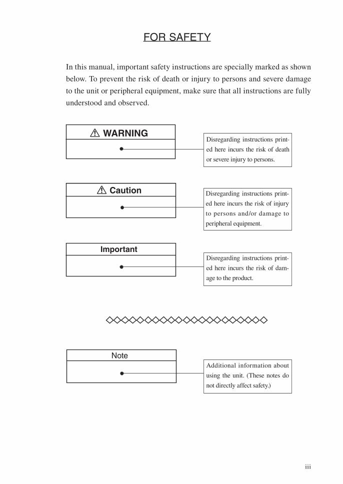
FOR SAFETY
In this manual, important safety instructions are specially marked as shown
below. To prevent the risk of death or injury to persons and severe damage
to the unit or peripheral equipment, make sure that all instructions are fully
understood and observed.
Caution
WARNING
Important
Disregarding instructions print-
ed here incurs the risk of death
or severe injury to persons.
Disregarding instructions print-
ed here incurs the risk of injury
to persons and/or damage to
peripheral equipment.
Disregarding instructions print-
ed here incurs the risk of dam-
age to the product.
Additional information about
using the unit. (These notes do
not directly affect safety.)
Note
iv
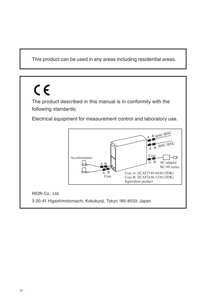
The product described in this manual is in conformity with the
following standards;
Electrical equipment for measurement control and laboratory use.
RION Co., Ltd.
3-20-41 Higashimotomachi, Kokubunji, Tokyo 185-8533, Japan
BNC-BNC
BNC-BNC
A B
A B
A B
A B
A B
AC adapterNC-99 series
Accelerometer
Core
Core
Core A: ZCAT2749-0430 (TDK)Core B: ZCAT2436-1330 (TDK)Equivalent product
This product can be used in any areas including residential areas.
v
Precautions
• Operate the unit only as described in this manual.
• Do not disassemble the unit or attempt internal alterations.
• Observe the following precautions before using the unit:
- Make sure that all connections are properly and safely established.
- Make sure that the unit is operating normally.
• The permissible ambient temperature range for operation of the unit is
−10°C to +50°C. Relative humidity must be 90% or below.
• The power cord used to connect the optional AC adapter to an AC outlet
is a 100 V AC cord for domestic use in Japan, which is compliant with
Japanese laws and electrical safety standards. Do not use this power cord
outside Japan or with any voltage other than 100 V AC. Otherwise, RION
cannot guarantee the safety of the equipment. Use a power cable that is
compliant with the laws and electrical safety standards of your location.
• If you notice any sign of a problem during use, disconnect the AC adapter
or battery unit, and contact your supplier.
• Do not use or store the unit in locations which
- may be subject to strong magnetic fi elds or strong radiation, or
- may be subject to high levels of dust or splashes of water, or
- may be subject to gases or air with high salt or sulphur content, or
are in the vicinity of stored chemicals, or
- may be subject to high temperature, humidity, or to direct sunlight, or
- may be subject vibrations or shock.
• Always switch off the power after using the unit.
• When disconnecting cables, always hold the plug and do not pull the cable.
• Use only the specifi ed AC adapter or other specifi ed power source.
• This is a precision device. Take care not to drop the unit and protect it
from shocks.
• The LCD panel of the unit can easily become scratched. Do not tap the
panel with a pointed object such as a pencil, screwdriver, etc.
• In case of malfunction, do not attempt any repairs. Note the condition of
the unit clearly and contact the supplier.
• When disposing of the unit, follow national and local regulations regarding
waste disposal.
vi
Contents
FOR SAFETY ............................................................................... iii
Precautions ......................................................................................v
Outline ............................................................................................1
Names of Parts and Functions .........................................................3
Front Panel ................................................................................3
Rear Panel .................................................................................5
Display screen ...........................................................................6
Bottom Panel .............................................................................8
Top Panel ...................................................................................8
Linking ...........................................................................................9
Linking procedure .....................................................................9
Removing the link connector ................................................... 14
Linking when using the Battery Unit BP-17 .............................15
Using a single UV-16 unit ........................................................ 16
Power Supply Connection .............................................................. 17
Using an AC adapter ................................................................ 18
Using the Battery Unit BP-17 ...................................................19
Accelerometer Selection and Connection ......................................21
Accelerometer connection ........................................................22
Accelerometer Mounting..........................................................23
Output Connections .......................................................................25
Measurement .................................................................................26
Operation mode .......................................................................26
Default settings...................................................................26
Accelerometer setup mode .......................................................27
Setup mode ..............................................................................29
Measurement mode .................................................................. 31
Bar graph indication ...........................................................33
Output signal ......................................................................33
Overload indicator LED .....................................................34
Calibration (CAL) mode ..........................................................35
vii
Performance Characteristics ..........................................................37
Specifi cations ................................................................................39
Rack Mounting Base .....................................................................44
Reference Material ........................................................................45
Lower measurement limit ........................................................45
Maintenance parts ...................................................................46

viii
1
Outline
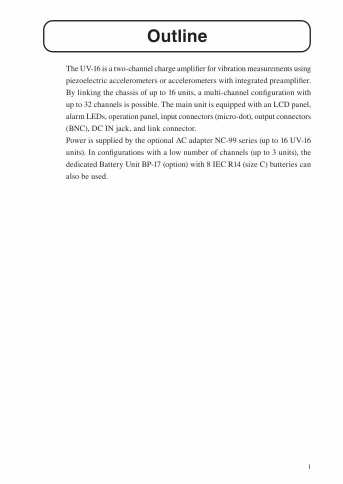
The UV-16 is a two-channel charge amplifi er for vibration measurements using
piezoelectric accelerometers or accelerometers with integrated preamplifi er.
By linking the chassis of up to 16 units, a multi-channel confi guration with
up to 32 channels is possible. The main unit is equipped with an LCD panel,
alarm LEDs, operation panel, input connectors (micro-dot), output connectors
(BNC), DC IN jack, and link connector.
Power is supplied by the optional AC adapter NC-99 series (up to 16 UV-16
units). In confi gurations with a low number of channels (up to 3 units), the
dedicated Battery Unit BP-17 (option) with 8 IEC R14 (size C) batteries can
also be used.
2
Outline
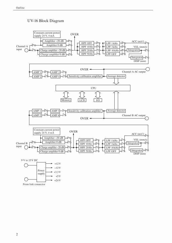
UV-16 Block Diagram
Channel A input
Channel A AC output
Charge amplifier −20 dB
Charge amplifier 0 dB
HPF OFFHPF 10 HzHPF 20 HzHPF 50 Hz
Integrator
AMP 2
AMP 1
AMP 4
AMP 3
LCD
CPU
Sensitivity calibration amplifier
Memory I/O
Channel B AC output
Powersupply
+12 V
−12 V
+3.3 V
+5 V
+24 V
9 V to 15 V DC
From link connector
Amplifier −20 dB
Amplifier 0 dB
Average detector
ACC (m/s2)
VEL (mm/s)
DISP (mm)
LPF 1 kHzLPF 3 kHzLPF 10 kHzLPF OFF
OVER
OVER
OVER
Constant-current power supply 24 V, 4 mA
Integrator
Channel B input Charge amplifier −20 dB
Charge amplifier 0 dB
Amplifier −20 dB
Amplifier 0 dB
Constant-current power supply 24 V, 4 mA
HPF OFFHPF 10 HzHPF 20 HzHPF 50 Hz
ACC (m/s2)
VEL (mm/s)
DISP (mm)
LPF 1 kHzLPF 3 kHzLPF 10 kHzLPF OFF
OVER
Integrator
Integrator
AMP 2
AMP 1
AMP 4
AMP 3 Average detectorSensitivity calibration amplifier
3
Names of Parts and Functions
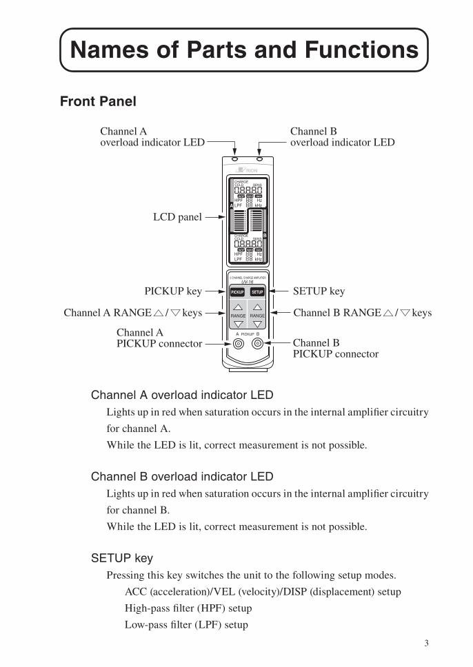
Front Panel
Channel A overload indicator LED
Lights up in red when saturation occurs in the internal amplifi er circuitry
for channel A.
While the LED is lit, correct measurement is not possible.
Channel B overload indicator LED
Lights up in red when saturation occurs in the internal amplifi er circuitry
for channel B.
While the LED is lit, correct measurement is not possible.
SETUP key
Pressing this key switches the unit to the following setup modes.
ACC (acceleration)/VEL (velocity)/DISP (displacement) setup
High-pass fi lter (HPF) setup
Low-pass fi lter (LPF) setup
CHARGECCLD SENS
m/s2 mm/s mm
HzkHz
CHARGECCLD SENS
m/s2 mm/s mm
HPFLPF
HzkHz
HPFLPFA
B
A PICKUP B
2 CHANNEL CHARGE AMPLIFIER
UV-16
PICKUP SETUP
RANGE RANGE
Channel A overload indicator LED
Channel B overload indicator LED
Channel B PICKUP connector
Channel A PICKUP connector
SETUP key
LCD panel
PICKUP key
Channel A RANGE / keys Channel B RANGE / keys
4
Names of Parts and Functions
Channel B RANGE / keysServe to select the range for channel B.
The key is also used to activate the CAL (calibration) mode.
Channel B PICKUP connectorServes for connection of the piezoelectric accelerometer or accelerometer
with integrated preamplifi er.
Channel A PICKUP connectorServes for connection of the piezoelectric accelerometer or accelerometer
with integrated preamplifi er.
Channel A RANGE / keysServe to select the range for channel A.
The key is also used to activate the CAL (calibration) mode.
PICKUP keyPressing this key switches the unit to the accelerometer setup modes below.
Setup for piezoelectric accelerometer/accelerometer with integrated
preamplifi er
Sensitivity setup
LCD panelShows various setup parameters and comprises two bar graph displays.
(For details, see page 6.)
5
Names of Parts and Functions
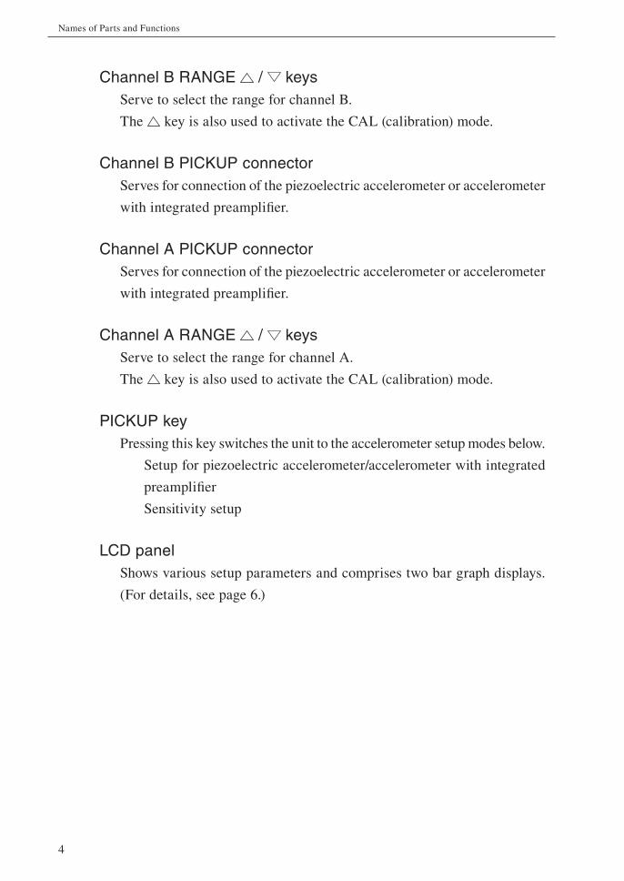
Rear Panel
Channel A AC OUT connectorSupplies an AC signal for channel A.
Channel B AC OUT connectorSupplies an AC signal for channel B.
Name plateShows the serial number and other information about the unit.
DC IN jackServes for connection of the optional AC adapter or an external DC source.
AC OUT
ch.A
ch.B
DC IN9-15V+
15
No. 12345678
RION CO.,LTD. MADE IN JAPAN
DC IN jack
Channel A AC OUT connector
Channel B AC OUT connector
Name plate
6
Names of Parts and Functions
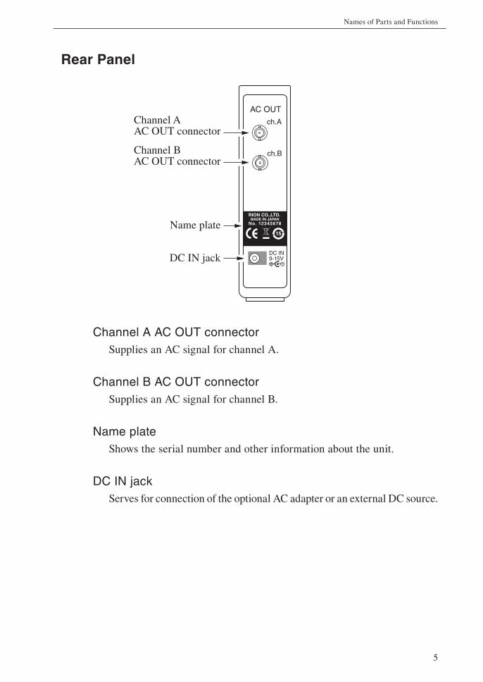
Display screen
The display serves for both the A and B channel, but the items are the same,
so the following explanation covers them together.
The illustration below shows all possible functions of the display. In actual
operation, not all indicators will light up simultaneously.
CHARGE/CCLD indicatorShows the accelerometer setting. When using a piezoelectric acceler-
ometer, select CHARGE. When using an accelerometer with integrated
preamplifi er, select CCLD.
SENS indicatorWhen the range/sensitivity readout shows the accelerometer sensitivity,
the SENS indicator lights up.
Range/sensitivity readoutNormally, this shows the range setting.
In calibration mode, the indication “CAL” is shown.
In accelerometer setup mode, the sensitivity setting is shown.
CHARGECCLD SENS
m/s2 mm/s mm
HzkHz
CHARGECCLD SENS
m/s2 mm/s mm
HPFLPF
HzkHz
HPFLPFA
BSENS indicator
Channel A section
Bar graph
CHARGE/CCLDindicator
Range/sensitivity readoutUnit indicatorsHPF indicatorsLPF indicators
CHARGE/CCLD indicatorSENS indicatorRange/sensitivity readoutUnit indicatorsHPF indicatorsLPF indicators
Bar graph
Channel B section
7
Names of Parts and Functions
Unit indicators
Show which unit is selected.
ACC (acceleration): m/s2
VEL (velocity): mm/s
DISP (displacement): mm
HPF indicators
Show the high-pass fi lter setting (OFF, 10 Hz, 20 Hz, 50 Hz). OFF is
indicated by “--”.
LPF indicators
Show the low-pass fi lter setting (1 kHz, 3 kHz, 10 kHz, OFF). OFF is
indicated by “--”.
Bar graph
Shows the level of the accelerometer signal as a bar graph indication. The
refresh rate of the display is 100 milliseconds.
Note
The display backlight is always on when the unit is
powered from an AC adapter. When the unit is pow-
ered from batteries using the Battery Unit BP-17, the
display backlight is activated for 10 seconds when
any key is pressed.
8
Names of Parts and Functions
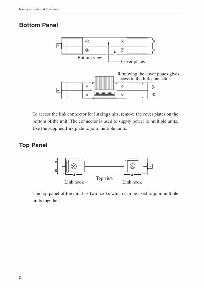
Bottom Panel
To access the link connector for linking units, remove the cover plates on the
bottom of the unit. The connector is used to supply power to multiple units.
Use the supplied link plate to join multiple units.
Top Panel
The top panel of the unit has two hooks which can be used to join multiple
units together.
Removing the cover plates gives access to the link connector.
Bottom viewCover plates
Link hookLink hookTop view
9
Linking
Multiple UV-16 units can be linked to form a multi-channel system.
The maximum number of units that can be linked is 16 (resulting in 32 channels).
When using the Battery Unit BP-17 to power the units, the maximum number
of units that can be linked is three.
Required tool: 1 Phillips screwdriver (JIS B 4633:1998, type H, No. 2)
ImportantPrecautions for linking units
• Make sure that power is OFF before starting:
• Disconnect AC adapter.
• When using Battery Unit BP-17: Remove
batteries
• Do not use any screws other than the ones
supplied with the product.
• Do not insert any objects (pieces of metal,
pencil lead, etc.) into the unit.
• Use only the specifi ed screwdriver (Phillips
screwdriver, JIS B 4633:1998, type H, No. 2).
Otherwise the cross-shaped slots on the
screw heads may be damaged.
Linking procedure
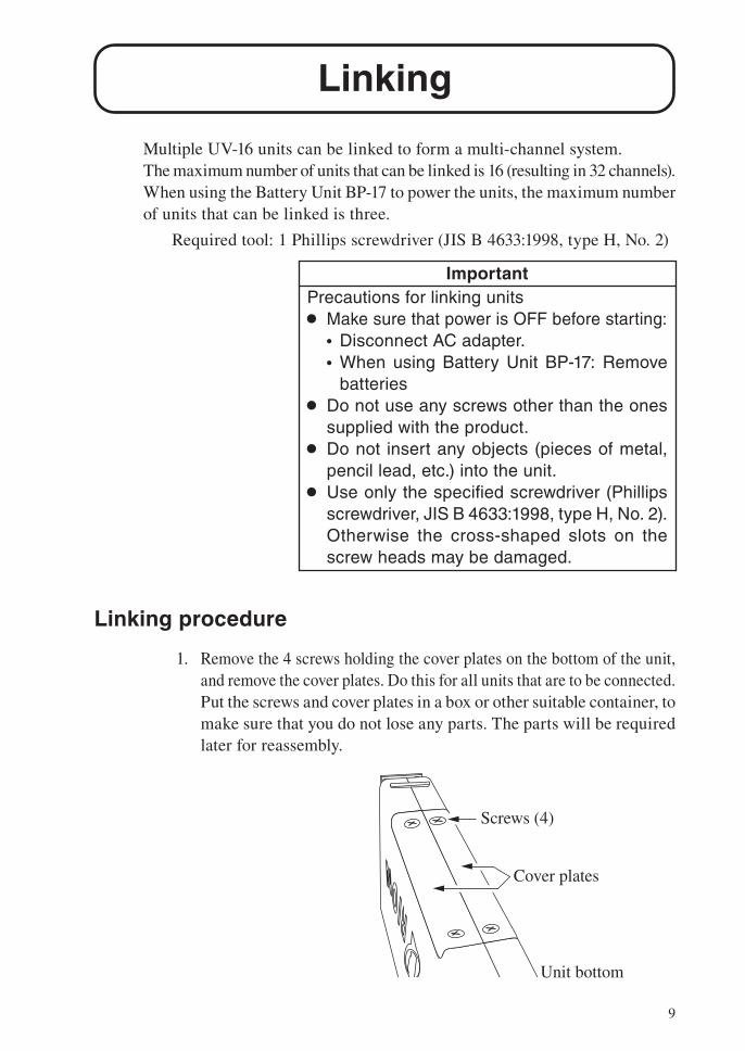
1. Remove the 4 screws holding the cover plates on the bottom of the unit,
and remove the cover plates. Do this for all units that are to be connected.
Put the screws and cover plates in a box or other suitable container, to
make sure that you do not lose any parts. The parts will be required
later for reassembly.
Unit bottom
Screws (4)
Cover plates
10
Linking
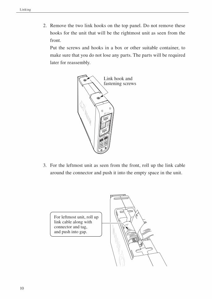
2. Remove the two link hooks on the top panel. Do not remove these
hooks for the unit that will be the rightmost unit as seen from the
front.
Put the screws and hooks in a box or other suitable container, to
make sure that you do not lose any parts. The parts will be required
later for reassembly.
3. For the leftmost unit as seen from the front, roll up the link cable
around the connector and push it into the empty space in the unit.
3M
J349
0-3
For leftmost unit, roll up link cable along with connector and tag, and push into gap.
Link hook and fastening screws
CHARGE
CCLD
SENS
m/s2mm/s mm
HPF
LPF
Hz
kHz
CHARGE
CCLD
SENS
m/s2mm/s
mm
HPF
LPF
Hz
kHz
A
B
A PICKUP B
RANGERANGE
PICKUP
SETUP
UV-16
11
Linking
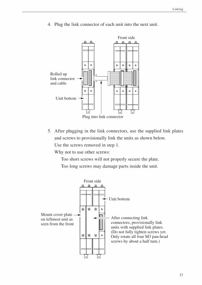
4. Plug the link connector of each unit into the next unit.
5. After plugging in the link connectors, use the supplied link plates
and screws to provisionally link the units as shown below.
Use the screws removed in step 1.
Why not to use other screws:
Too short screws will not properly secure the plate.
Too long screws may damage parts inside the unit.
After connecting link connectors, provisionally link units with supplied link plates.(Do not fully tighten screws yet. Only rotate all four M3 pan-head screws by about a half turn.)
Front side
Mount cover plate on leftmost unit as seen from the front
Unit bottom
Plug into link connector
Front side
Rolled up link connector and cable
Unit bottom
12
Linking
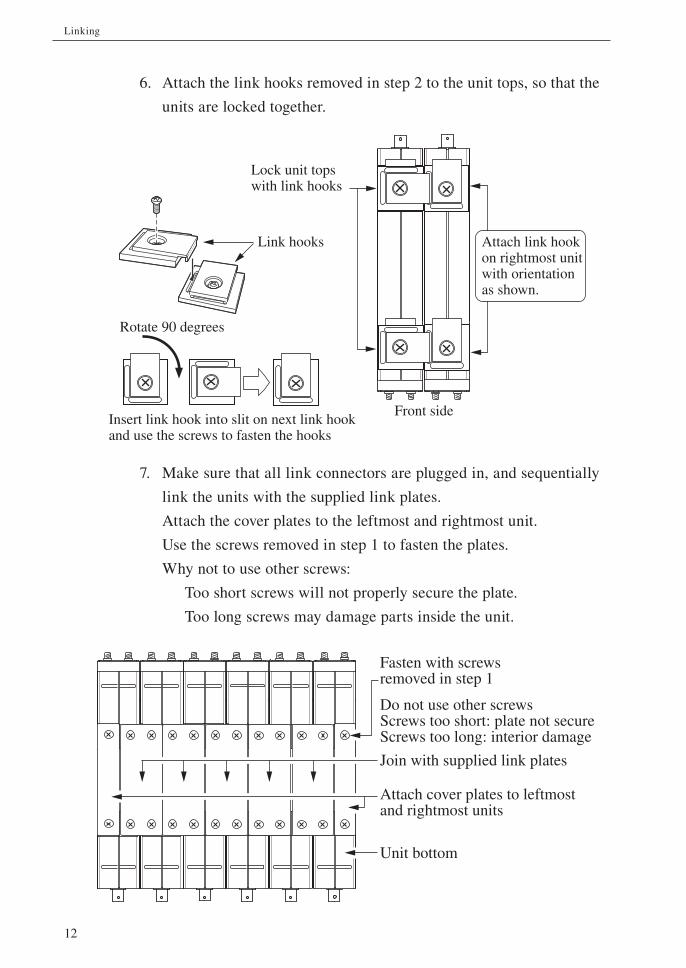
6. Attach the link hooks removed in step 2 to the unit tops, so that the
units are locked together.
7. Make sure that all link connectors are plugged in, and sequentially
link the units with the supplied link plates.
Attach the cover plates to the leftmost and rightmost unit.
Use the screws removed in step 1 to fasten the plates.
Why not to use other screws:
Too short screws will not properly secure the plate.
Too long screws may damage parts inside the unit.
Insert link hook into slit on next link hook and use the screws to fasten the hooks
Lock unit tops with link hooks
Link hooks Attach link hook on rightmost unit with orientation as shown.
Rotate 90 degrees
Front side
Unit bottom
Fasten with screws removed in step 1
Do not use other screwsScrews too short: plate not secureScrews too long: interior damage
Join with supplied link plates
Attach cover plates to leftmost and rightmost units
13
Linking
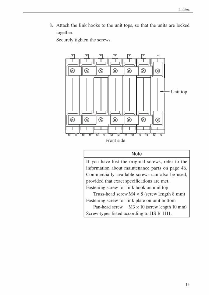
8. Attach the link hooks to the unit tops, so that the units are locked
together.
Securely tighten the screws.
Note
If you have lost the original screws, refer to the
information about maintenance parts on page 46.
Commercially available screws can also be used,
provided that exact specifi cations are met.
Fastening screw for link hook on unit top
Truss-head screw M4 × 8 (screw length 8 mm)
Fastening screw for link plate on unit bottom
Pan-head screw M3 × 10 (screw length 10 mm)
Screw types listed according to JIS B 1111.
Front side
Unit top
14
Linking
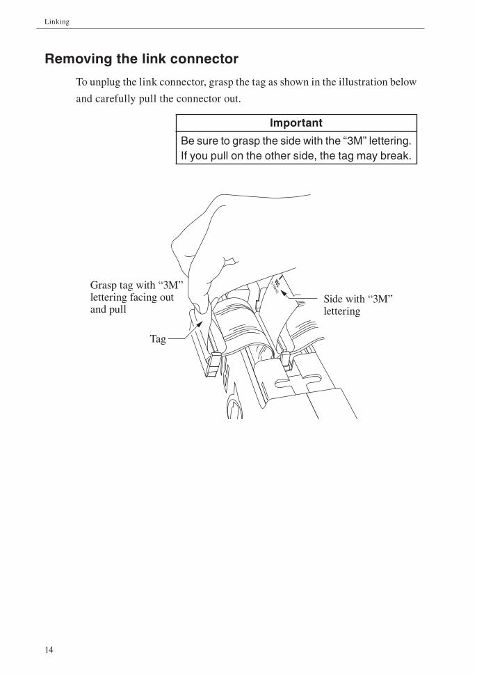
Removing the link connector
To unplug the link connector, grasp the tag as shown in the illustration below
and carefully pull the connector out.
Important
Be sure to grasp the side with the “3M” lettering. If you pull on the other side, the tag may break.
3M
J349
0-3
Side with “3M” lettering
Grasp tag with “3M” lettering facing out and pull
Tag
15
Linking
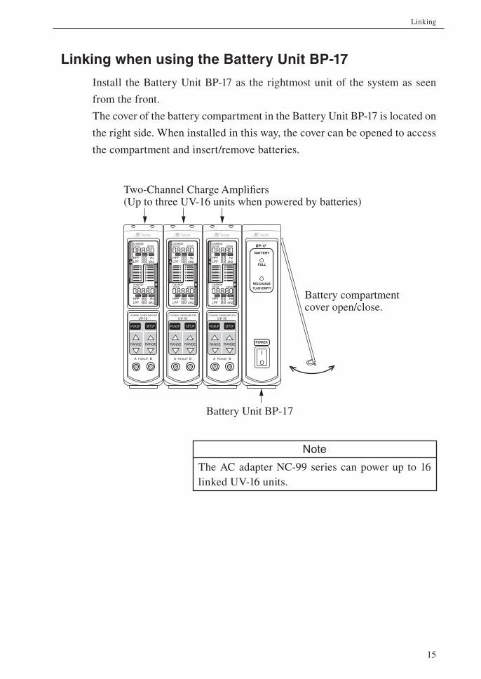
Linking when using the Battery Unit BP-17
Install the Battery Unit BP-17 as the rightmost unit of the system as seen
from the front.
The cover of the battery compartment in the Battery Unit BP-17 is located on
the right side. When installed in this way, the cover can be opened to access
the compartment and insert/remove batteries.
Note
The AC adapter NC-99 series can power up to 16
linked UV-16 units.
CHARGECCLD SENS
m/s2 mm/s mm
HzkHz
CHARGECCLD SENS
m/s2 mm/s mm
HPFLPF
HzkHz
HPFLPFA
B
A PICKUP B
2 CHANNEL CHARGE AMPLIFIER
UV-16
PICKUP SETUP
RANGE RANGE
CHARGECCLD SENS
m/s2 mm/s mm
HzkHz
CHARGECCLD SENS
m/s2 mm/s mm
HPFLPF
HzkHz
HPFLPFA
B
A PICKUP B
2 CHANNEL CHARGE AMPLIFIER
UV-16
PICKUP SETUP
RANGE RANGE
CHARGECCLD SENS
m/s2 mm/s mm
HzkHz
CHARGECCLD SENS
m/s2 mm/s mm
HPFLPF
HzkHz
HPFLPFA
B
A PICKUP B
2 CHANNEL CHARGE AMPLIFIER
UV-16
PICKUP SETUP
RANGE RANGE
Battery Unit BP-17
Two-Channel Charge Amplifiers(Up to three UV-16 units when powered by batteries)
Battery compartment cover open/close.
I
O
BP-17
BATTERY
FULL
RED:CHANGE
POWER
FLASH:EMPTY
16
Linking
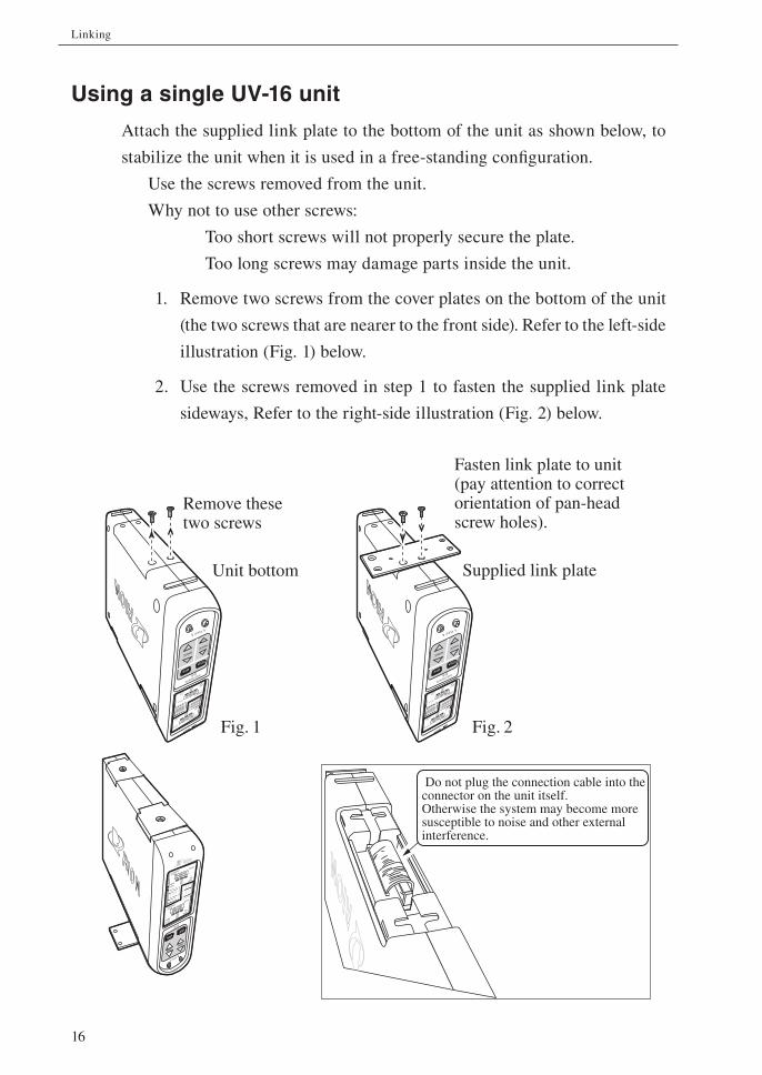
Using a single UV-16 unit
Attach the supplied link plate to the bottom of the unit as shown below, to
stabilize the unit when it is used in a free-standing confi guration.
Use the screws removed from the unit.
Why not to use other screws:
Too short screws will not properly secure the plate.
Too long screws may damage parts inside the unit.
1. Remove two screws from the cover plates on the bottom of the unit
(the two screws that are nearer to the front side). Refer to the left-side
illustration (Fig. 1) below.
2. Use the screws removed in step 1 to fasten the supplied link plate
sideways, Refer to the right-side illustration (Fig. 2) below.
AB
CHARGE
CCLD
SENS
m/s2mm/s
mm
HPF
LPF
Hz
kHz
CH
ARG
E
CC
LD
SE
NS
m/s2
mm/smm
HPF
LPF
Hz
kHz
A PICKUP B
RANGERANGE
PICKUP
SETUP2 CHANNEL CHARGE AMPLIFIER
UV-16
Unit bottom
Remove these two screws
AB
CHARGE
CCLD
SENS
m/s2mm/s
mm
HPF
LPF
Hz
kHz
CH
ARG
E
CC
LD
SE
NS
m/s2
mm/smm
HPF
LPF
Hz
kHz
A PICKUP B
RANGERANGE
PICKUP
SETUP2 CHANNEL CHARGE AMPLIFIER
UV-16
Fasten link plate to unit (pay attention to correct orientation of pan-head screw holes).
Supplied link plate
Fig. 1 Fig. 2
CHARGE
CCLD
SENS
m/s2mm/s mm
HPF
LPF
Hz
kHz
CHARGE
CCLD
SENS
m/s2mm/s
mm
HPF
LPF
Hz
kHz
A
B
A PICKUP B
RANGERANGE
PICKUP
SETUP
UV-16
Do not plug the connection cable into the connector on the unit itself.Otherwise the system may become moresusceptible to noise and other external interference.
17
Power Supply Connection
The UV-16 can be powered from an AC adapter (option), the Battery Unit
BP-17 (option), or a car battery (12 V).
The UV-16 does not have a power switch. It will start to operate when power
is supplied.
The Battery Unit BP-17 (option) has a power switch which allows shutting
down the system.
ImportantWhen using multiple units in a linked confi gu-
ration, make sure that system assembly is fully
completed before supplying power.
Power supply limitations
Power supply type Max. number of units
AC adapter (option) NC-99 series Up to 16
Battery Unit BP-17 (option) IEC R14 (size C) battery × 8 Up to 3
Note
The display backlight is always on when the unit is
powered from an AC adapter. When the unit is pow-
ered from batteries using the Battery Unit BP-17, the
display backlight is activated for 10 seconds when
any key is pressed.
To power a system in which the Battery Unit BP-17
is installed from an AC adapter, be sure to connect
the AC adapter to the BP-17.
The UV-16 does not have a power switch. It will start
to operate when power is supplied.
18
Power Supply Connection
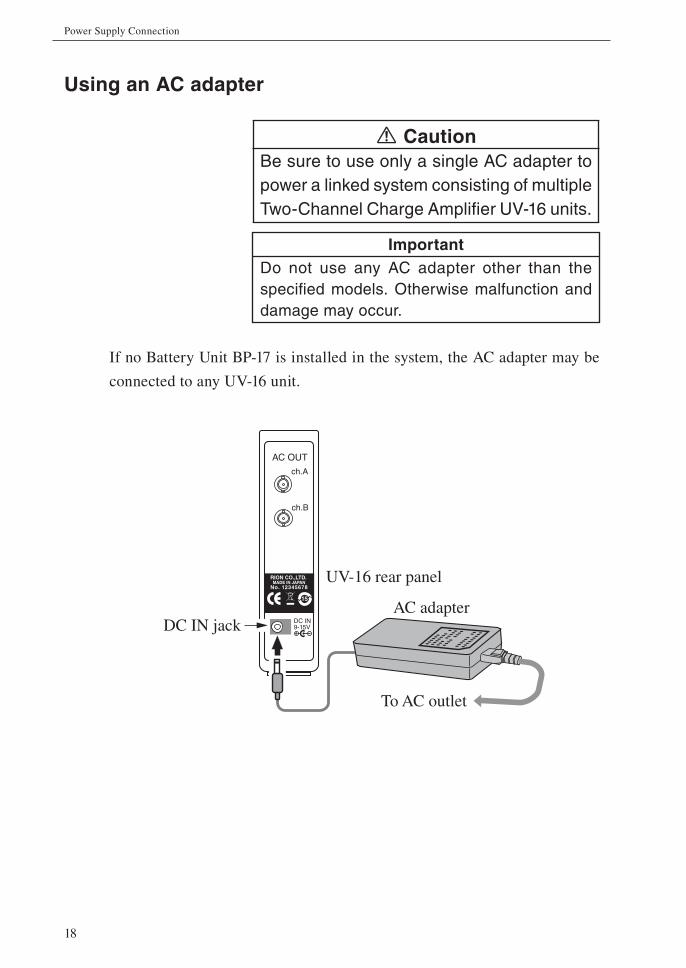
Using an AC adapter
CautionBe sure to use only a single AC adapter to
power a linked system consisting of multiple
Two-Channel Charge Amplifi er UV-16 units.
ImportantDo not use any AC adapter other than the
specifi ed models. Otherwise malfunction and
damage may occur.
If no Battery Unit BP-17 is installed in the system, the AC adapter may be
connected to any UV-16 unit.
AC OUT
ch.A
ch.B
DC IN9-15V+
15
No. 12345678
RION CO.,LTD. MADE IN JAPAN
DC IN jack
UV-16 rear panel
To AC outlet
AC adapter
19
Power Supply Connection
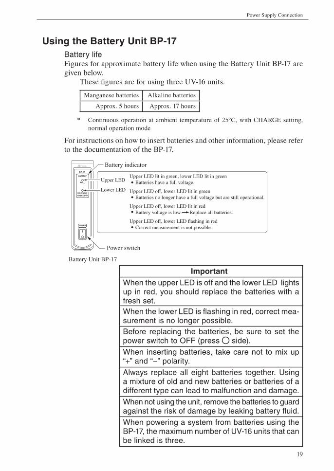
Using the Battery Unit BP-17Battery lifeFigures for approximate battery life when using the Battery Unit BP-17 are
given below.
These fi gures are for using three UV-16 units.
Manganese batteries Alkaline batteries
Approx. 5 hours Approx. 17 hours
* Continuous operation at ambient temperature of 25°C, with CHARGE setting,
normal operation mode
For instructions on how to insert batteries and other information, please refer
to the documentation of the BP-17.
ImportantWhen the upper LED is off and the lower LED lights up in red, you should replace the batteries with a fresh set.
When the lower LED is fl ashing in red, correct mea-surement is no longer possible.
Before replacing the batteries, be sure to set the power switch to OFF (press side).
When inserting batteries, take care not to mix up “+” and “−” polarity.
Always replace all eight batteries together. Using a mixture of old and new batteries or batteries of a different type can lead to malfunction and damage.
When not using the unit, remove the batteries to guard against the risk of damage by leaking battery fl uid.
When powering a system from batteries using the BP-17, the maximum number of UV-16 units that can be linked is three.
Battery indicator
Power switch
Battery Unit BP-17
I
O
BP-17
BATTERY
FULL
RED:CHANGE
POWER
FLASH:EMPTY
Upper LED
Lower LED
Upper LED lit in green, lower LED lit in green Batteries have a full voltage.
Upper LED off, lower LED lit in green Batteries no longer have a full voltage but are still operational.
Upper LED off, lower LED lit in red Battery voltage is low. Replace all batteries.
Upper LED off, lower LED flashing in red Correct measurement is not possible.
20
Power Supply Connection
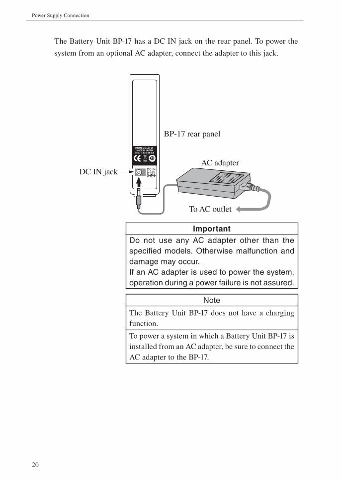
The Battery Unit BP-17 has a DC IN jack on the rear panel. To power the
system from an optional AC adapter, connect the adapter to this jack.
ImportantDo not use any AC adapter other than the
specifi ed models. Otherwise malfunction and
damage may occur.
If an AC adapter is used to power the system,
operation during a power failure is not assured.
Note
The Battery Unit BP-17 does not have a charging
function.
To power a system in which a Battery Unit BP-17 is
installed from an AC adapter, be sure to connect the
AC adapter to the BP-17.
DC IN9-15V+
15
No. 12345678
RION CO.,LTD. MADE IN JAPAN
DC IN jack
BP-17 rear panel
To AC outlet
AC adapter
21
Accelerometer Selection and Connection
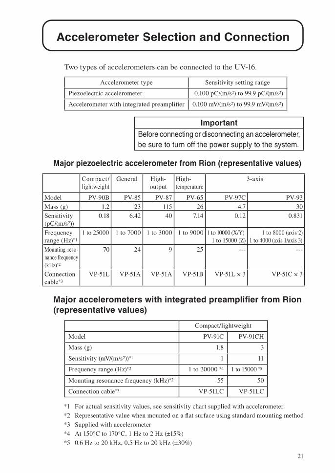
Two types of accelerometers can be connected to the UV-16.
Accelerometer type Sensitivity setting range
Piezoelectric accelerometer 0.100 pC/(m/s2) to 99.9 pC/(m/s2)
Accelerometer with integrated preamplifi er 0.100 mV/(m/s2) to 99.9 mV/(m/s2)
ImportantBefore connecting or disconnecting an accelerometer, be sure to turn off the power supply to the system.
Major piezoelectric accelerometer from Rion (representative values)
Compact /
lightweight
General High-
output
High-
temperature
3-axis
Model PV-90B PV-85 PV-87 PV-65 PV-97C PV-93
Mass (g) 1.2 23 115 26 4.7 30
Sensitivity
(pC/(m/s2))
0.18 6.42 40 7.14 0.12 0.831
Frequency
range (Hz)*1
1 to 25000 1 to 7000 1 to 3000 1 to 9000 1 to 10000 (X/Y)
1 to 15000 (Z)
1 to 8000 (axis 2)
1 to 4000 (axis 1/axis 3)
Mounting reso-
nance frequency
(kHz)*2
70 24 9 25 --- ---
Connection
cable*3
VP-51L VP-51A VP-51A VP-51B VP-51L × 3 VP-51C × 3
Major accelerometers with integrated preamplifi er from Rion (representative values)
Compact/lightweight
Model PV-91C PV-91CH
Mass (g) 1.8 3
Sensitivity (mV/(m/s2))*1 1 11
Frequency range (Hz)*2 1 to 20000 *4 1 to 15000 *5
Mounting resonance frequency (kHz)*2 55 50
Connection cable*3 VP-51LC VP-51LC
*1 For actual sensitivity values, see sensitivity chart supplied with accelerometer.
*2 Representative value when mounted on a fl at surface using standard mounting method
*3 Supplied with accelerometer
*4 At 150°C to 170°C, 1 Hz to 2 Hz (±15%)
*5 0.6 Hz to 20 kHz, 0.5 Hz to 20 kHz (±30%)
22
Accelerometer Selection and Connection
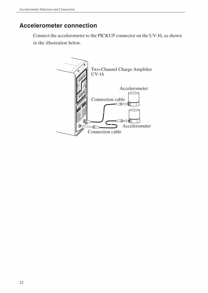
Accelerometer connection
Connect the accelerometer to the PICKUP connector on the UV-16, as shown
in the illustration below.
CHARGE
CCLD
SENS
m/s
2m
m/s
mm
Hz
kHz
CHARGE
CCLD
SENS
m/s
2m
m/s
mm
HPF
LPF
Hz
kHz
HPF
LPF
AB
A PIC
KUP B
2 CHANNEL C
HARGE AMPLIFIE
R
UV-16
PICKUP
SETUP
RANGE
RANGE
Connection cable
Two-Channel Charge Amplifier UV-16
Accelerometer
Connection cable
Accelerometer
23
Accelerometer Selection and Connection
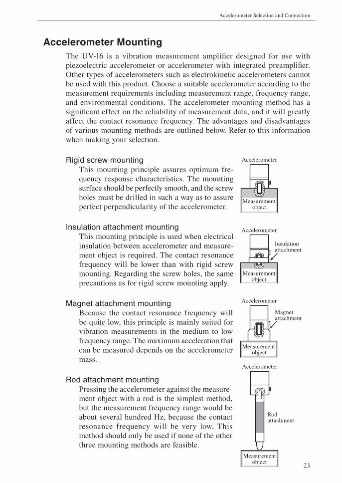
Accelerometer MountingThe UV-16 is a vibration measurement amplifi er designed for use with
piezoelectric accelerometer or accelerometer with integrated preamplifi er.
Other types of accelerometers such as electrokinetic accelerometers cannot
be used with this product. Choose a suitable accelerometer according to the
measurement requirements including measurement range, frequency range,
and environmental conditions. The accelerometer mounting method has a
signifi cant effect on the reliability of measurement data, and it will greatly
affect the contact resonance frequency. The advantages and disadvantages
of various mounting methods are outlined below. Refer to this information
when making your selection.
Rigid screw mountingThis mounting principle assures optimum fre-
quency response characteristics. The mounting
surface should be perfectly smooth, and the screw
holes must be drilled in such a way as to assure
perfect perpendicularity of the accelerometer.
Insulation attachment mountingThis mounting principle is used when electrical
insulation between accelerometer and measure-
ment object is required. The contact resonance
frequency will be lower than with rigid screw
mounting. Regarding the screw holes, the same
precautions as for rigid screw mounting apply.
Magnet attachment mountingBecause the contact resonance frequency will
be quite low, this principle is mainly suited for
vibration measurements in the medium to low
frequency range. The maximum acceleration that
can be measured depends on the accelerometer
mass.
Rod attachment mountingPressing the accelerometer against the measure-
ment object with a rod is the simplest method,
but the measurement frequency range would be
about several hundred Hz, because the contact
resonance frequency will be very low. This
method should only be used if none of the other
three mounting methods are feasible.
Measurement object
Accelerometer
Accelerometer
Insulation attachment
Measurementobject
Measurement object
Magnet attachment
Accelerometer
Measurementobject
Rod attachment
Accelerometer
24
Accelerometer Selection and Connection
WARNINGWhen performing measurements on ma-chinery with exposed rotating parts or drive train parts, proceed with utmost caution to avoid the risk of getting caught in the machinery.
Note
Tighten the M6 screw fi rst on the piezoelectric ac-
celerometer side and then mount the rod attachment.
25
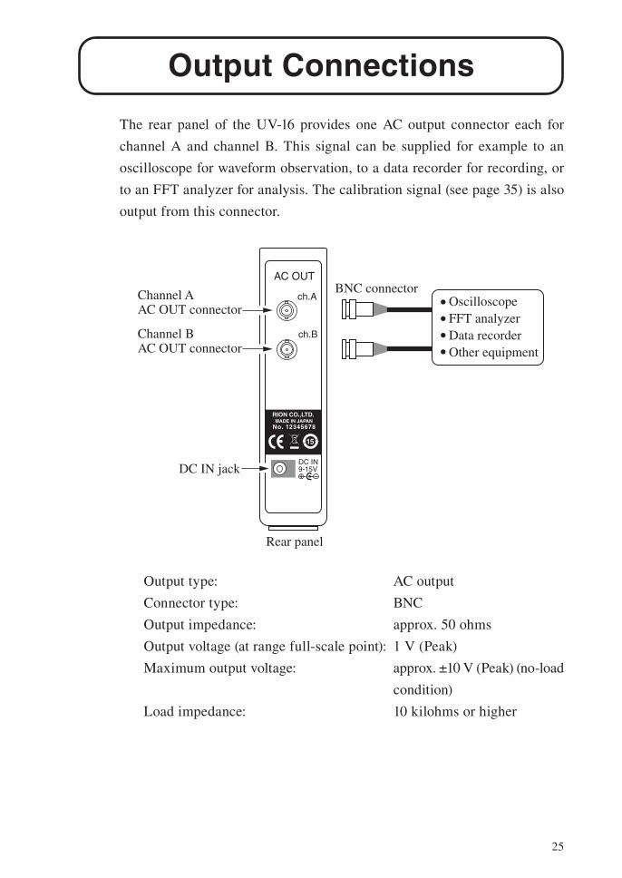
Output Connections
The rear panel of the UV-16 provides one AC output connector each for
channel A and channel B. This signal can be supplied for example to an
oscilloscope for waveform observation, to a data recorder for recording, or
to an FFT analyzer for analysis. The calibration signal (see page 35) is also
output from this connector.
Output type: AC output
Connector type: BNC
Output impedance: approx. 50 ohms
Output voltage (at range full-scale point): 1 V (Peak)
Maximum output voltage: approx. ±10 V (Peak) (no-load
condition)
Load impedance: 10 kilohms or higher
AC OUT
ch.A
ch.B
DC IN9-15V+
15
No. 12345678
RION CO.,LTD. MADE IN JAPAN
Rear panel
Channel A AC OUT connector
Channel B AC OUT connector
BNC connectorOscilloscopeFFT analyzerData recorderOther equipment
DC IN jack
26
Measurement
Operation modeThe operation modes of the UV-16 are listed below.
Operation mode Outline
Accelerometer setup mode Make accelerometer sensitivity settings
Setup mode Make acceleration/velocity/displacement settings,
HPF setting, LPF settings
Measurement mode Make measurements
Calibration (CAL) mode Use a calibration output signal to calibrate external
equipment
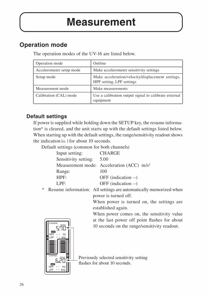
Default settingsIf power is supplied while holding down the SETUP key, the resume informa-
tion* is cleared, and the unit starts up with the default settings listed below.
When starting up with the default settings, the range/sensitivity readout shows
the indication for about 10 seconds.
Default settings (common for both channels)
Input setting: CHARGE
Sensitivity setting: 5.00
Measurement mode: Acceleration (ACC) m/s2
Range: 100
HPF: OFF (indication --)
LPF: OFF (indication --)
* Resume information: All settings are automatically memorized when
power is turned off.
When power is turned on, the settings are
established again.
When power comes on, the sensitivity value
at the last power off point fl ashes for about
10 seconds on the range/sensitivity readout.CHARGE
SENS
m/s2
HzkHz
CHARGESENS
m/s2
HPFLPF
HzkHz
HPFLPFA
B Previously selected sensitivity setting flashes for about 10 seconds.
27
Measurement
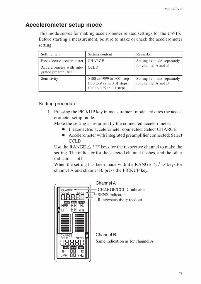
Accelerometer setup modeThis mode serves for making accelerometer related settings for the UV-16.
Before starting a measurement, be sure to make or check the accelerometer
setting.
Setting item Setting content Remarks
Piezoelectric accelerometer CHARGE Setting is made separately
for channel A and BAccelerometer with inte-
grated preamplifi er
CCLD
Sensitivity 0.100 to 0.999 in 0.001 steps
1.00 to 9.99 in 0.01 steps
10.0 to 99.9 in 0.1 steps
Setting is made separately
for channel A and B
Setting procedure
1. Pressing the PICKUP key in measurement mode activates the accel-
erometer setup mode.
Make the setting as required by the connected accelerometer.
• Piezoelectric accelerometer connected: Select CHARGE
• Accelerometer with integrated preamplifi er connected: Select
CCLD
Use the RANGE / keys for the respective channel to make the
setting. The indicator for the selected channel fl ashes, and the other
indicator is off.
When the setting has been made with the RANGE / keys for
channel A and channel B, press the PICKUP key.
CHARGECCLD SENS
m/s2 mm/s mm
HzkHz
CHARGECCLD SENS
m/s2 mm/s mm
HPFLPF
HzkHz
HPFLPFA
BSame indication as for channel A
Channel A
CHARGE/CCLD indicatorSENS indicatorRange/sensitivity readout
Channel B
28
Measurement
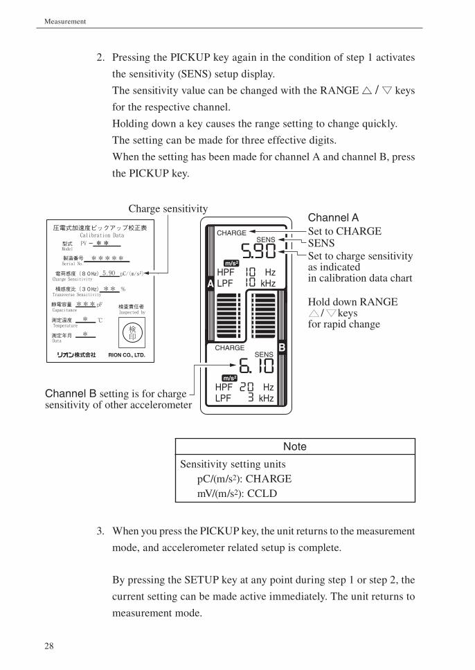
2. Pressing the PICKUP key again in the condition of step 1 activates
the sensitivity (SENS) setup display.
The sensitivity value can be changed with the RANGE / keys
for the respective channel.
Holding down a key causes the range setting to change quickly.
The setting can be made for three effective digits.
When the setting has been made for channel A and channel B, press
the PICKUP key.
Note
Sensitivity setting units
pC/(m/s2): CHARGE
mV/(m/s2): CCLD
3. When you press the PICKUP key, the unit returns to the measurement
mode, and accelerometer related setup is complete.
By pressing the SETUP key at any point during step 1 or step 2, the
current setting can be made active immediately. The unit returns to
measurement mode.
CHARGESENS
m/s2
HzkHz
CHARGESENS
m/s2
HPFLPF
HzkHz
HPFLPFA
B
Hold down RANGE / keys
for rapid change
Charge sensitivity
Channel B setting is for charge sensitivity of other accelerometer
Channel ASet to CHARGESENSSet to charge sensitivity as indicated in calibration data chart
29
Measurement
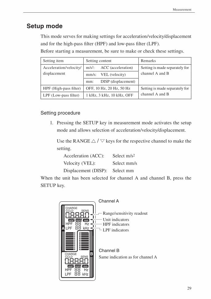
Setup mode
This mode serves for making settings for acceleration/velocity/displacement
and for the high-pass fi lter (HPF) and low-pass fi lter (LPF).
Before starting a measurement, be sure to make or check these settings.
Setting item Setting content Remarks
Acceleration/velocity/
displacement
m/s2: ACC (acceleration) Setting is made separately for
channel A and Bmm/s: VEL (velocity)
mm: DISP (displacement)
HPF (High-pass fi lter) OFF, 10 Hz, 20 Hz, 50 Hz Setting is made separately for
channel A and BLPF (Low-pass fi lter) 1 kHz, 3 kHz, 10 kHz, OFF
Setting procedure
1. Pressing the SETUP key in measurement mode activates the setup
mode and allows selection of acceleration/velocity/displacement.
Use the RANGE / keys for the respective channel to make the
setting.
Acceleration (ACC): Select m/s2
Velocity (VEL): Select mm/s
Displacement (DISP): Select mm
When the unit has been selected for channel A and channel B, press the
SETUP key.
CHARGECCLD SENS
m/s2 mm/s mm
HzkHz
CHARGECCLD SENS
m/s2 mm/s mm
HPFLPF
HzkHz
HPFLPFA
BSame indication as for channel A
Channel A
Range/sensitivity readout
Unit indicatorsHPF indicatorsLPF indicators
Channel B
30
Measurement
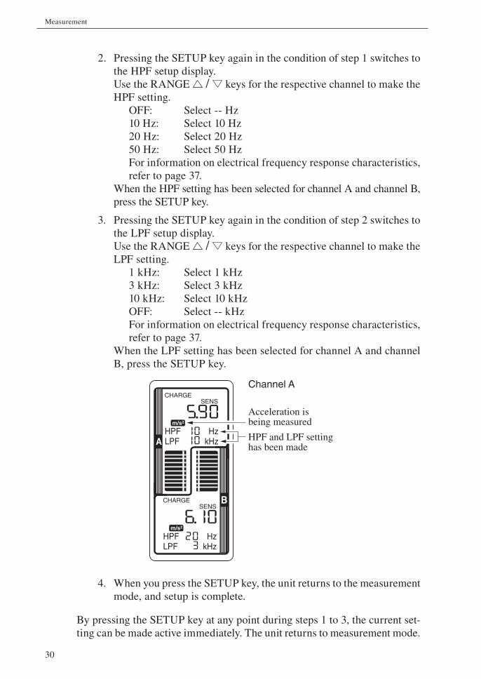
2. Pressing the SETUP key again in the condition of step 1 switches to
the HPF setup display.
Use the RANGE / keys for the respective channel to make the
HPF setting.
OFF: Select -- Hz
10 Hz: Select 10 Hz
20 Hz: Select 20 Hz
50 Hz: Select 50 Hz
For information on electrical frequency response characteristics,
refer to page 37.
When the HPF setting has been selected for channel A and channel B,
press the SETUP key.
3. Pressing the SETUP key again in the condition of step 2 switches to
the LPF setup display.
Use the RANGE / keys for the respective channel to make the
LPF setting.
1 kHz: Select 1 kHz
3 kHz: Select 3 kHz
10 kHz: Select 10 kHz
OFF: Select -- kHz
For information on electrical frequency response characteristics,
refer to page 37.
When the LPF setting has been selected for channel A and channel
B, press the SETUP key.
4. When you press the SETUP key, the unit returns to the measurement
mode, and setup is complete.
By pressing the SETUP key at any point during steps 1 to 3, the current set-
ting can be made active immediately. The unit returns to measurement mode.
CHARGESENS
m/s2
HzkHz
CHARGESENS
m/s2
HPFLPF
HzkHz
HPFLPFA
B
HPF and LPF setting has been made
Channel A
Acceleration is being measured
31
Measurement
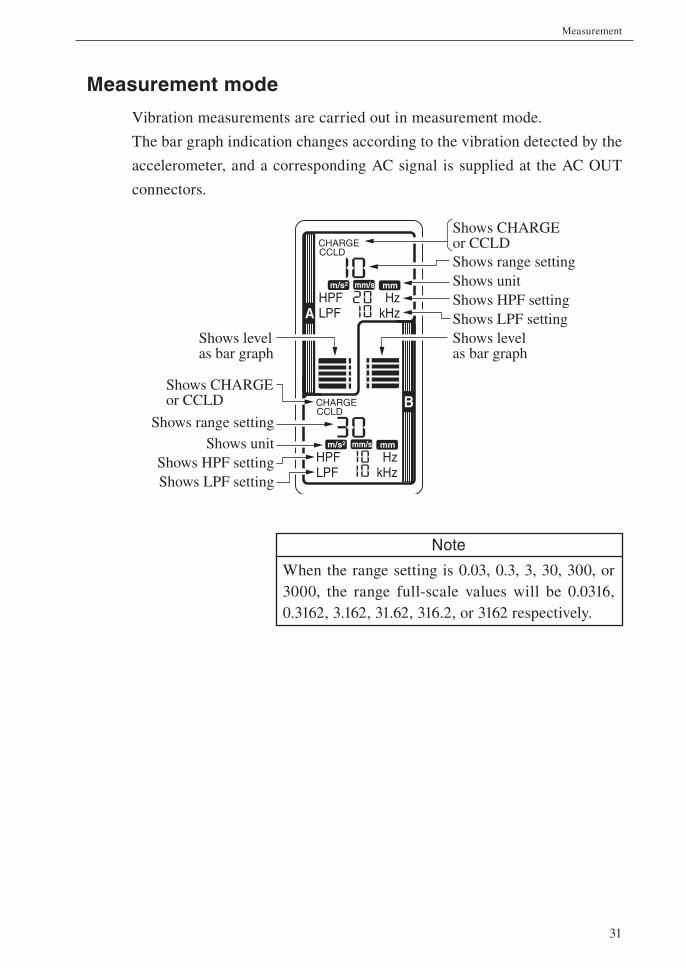
Measurement mode
Vibration measurements are carried out in measurement mode.
The bar graph indication changes according to the vibration detected by the
accelerometer, and a corresponding AC signal is supplied at the AC OUT
connectors.
Note
When the range setting is 0.03, 0.3, 3, 30, 300, or
3000, the range full-scale values will be 0.0316,
0.3162, 3.162, 31.62, 316.2, or 3162 respectively.
CHARGECCLD
m/s2 mm/s mm
HzkHz
CHARGECCLD
m/s2 mm/s mm
HPFLPF
HzkHz
HPFLPFA
B
Shows unitShows HPF settingShows LPF setting
Shows range settingShows unitShows HPF settingShows LPF setting
Shows CHARGE or CCLD
Shows level as bar graph
Shows level as bar graph
Shows CHARGE or CCLD
Shows range setting
32
Measurement
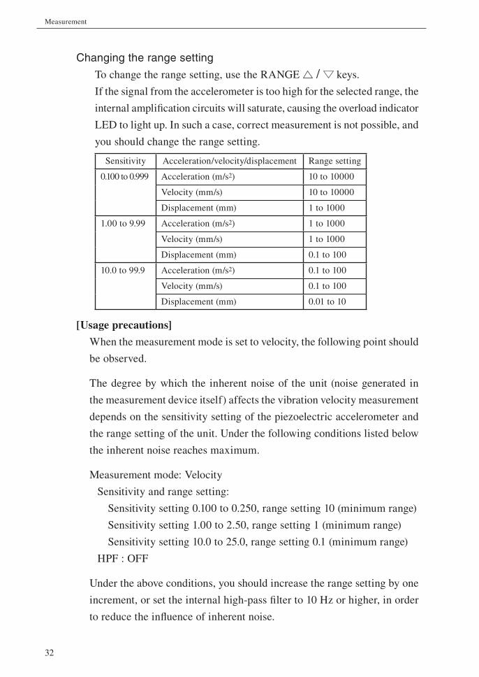
Changing the range setting
To change the range setting, use the RANGE / keys.
If the signal from the accelerometer is too high for the selected range, the
internal amplifi cation circuits will saturate, causing the overload indicator
LED to light up. In such a case, correct measurement is not possible, and
you should change the range setting.
Sensitivity Acceleration/velocity/displacement Range setting
0.100 to 0.999 Acceleration (m/s2) 10 to 10000
Velocity (mm/s) 10 to 10000
Displacement (mm) 1 to 1000
1.00 to 9.99 Acceleration (m/s2) 1 to 1000
Velocity (mm/s) 1 to 1000
Displacement (mm) 0.1 to 100
10.0 to 99.9 Acceleration (m/s2) 0.1 to 100
Velocity (mm/s) 0.1 to 100
Displacement (mm) 0.01 to 10
[Usage precautions]
When the measurement mode is set to velocity, the following point should
be observed.
The degree by which the inherent noise of the unit (noise generated in
the measurement device itself) affects the vibration velocity measurement
depends on the sensitivity setting of the piezoelectric accelerometer and
the range setting of the unit. Under the following conditions listed below
the inherent noise reaches maximum.
Measurement mode: Velocity
Sensitivity and range setting:
Sensitivity setting 0.100 to 0.250, range setting 10 (minimum range)
Sensitivity setting 1.00 to 2.50, range setting 1 (minimum range)
Sensitivity setting 10.0 to 25.0, range setting 0.1 (minimum range)
HPF : OFF
Under the above conditions, you should increase the range setting by one
increment, or set the internal high-pass fi lter to 10 Hz or higher, in order
to reduce the infl uence of inherent noise.
33
Measurement
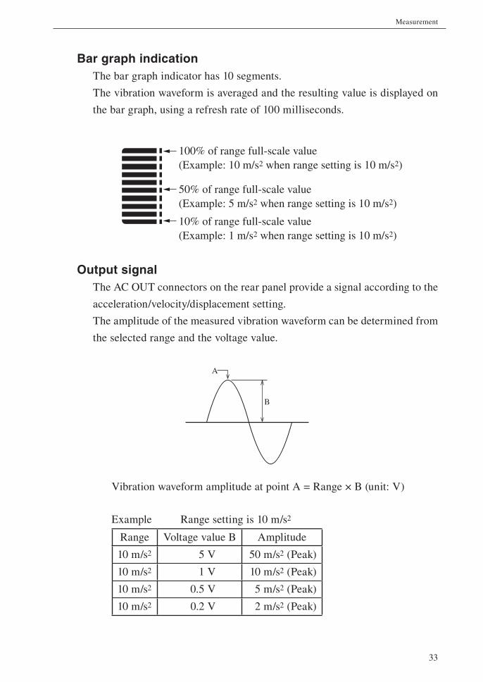
10% of range full-scale value(Example: 1 m/s2 when range setting is 10 m/s2)
100% of range full-scale value(Example: 10 m/s2 when range setting is 10 m/s2)
50% of range full-scale value(Example: 5 m/s2 when range setting is 10 m/s2)
Bar graph indicationThe bar graph indicator has 10 segments.
The vibration waveform is averaged and the resulting value is displayed on
the bar graph, using a refresh rate of 100 milliseconds.
Output signalThe AC OUT connectors on the rear panel provide a signal according to the
acceleration/velocity/displacement setting.
The amplitude of the measured vibration waveform can be determined from
the selected range and the voltage value.
A
B
Vibration waveform amplitude at point A = Range × B (unit: V)
Example Range setting is 10 m/s2
Range Voltage value B Amplitude
10 m/s2 5 V 50 m/s2 (Peak)
10 m/s2 1 V 10 m/s2 (Peak)
10 m/s2 0.5 V 5 m/s2 (Peak)
10 m/s2 0.2 V 2 m/s2 (Peak)
34
Measurement
Overload indicator LEDAt each range setting, measurement is possible up to a point about ten times
(+20 dB) higher than the range full-scale point. For example, if the range setting
is 10 m/s2, measurement is possible up to about 100 m/s2 without saturation.
Because velocity and displacement are calculated by integration from the
acceleration signal, the upper measurement limit for these items is determined
by the upper measurement limit for acceleration and the frequency.
Note
When the range setting is 0.03, 0.3, 3, 30, 300, or
3000, the range full-scale values will be 0.0316,
0.3162, 3.162, 31.62, 316.2, or 3162 respectively.
35
Measurement
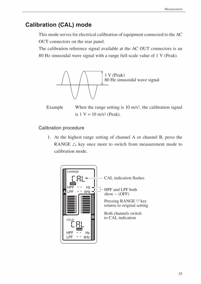
Calibration (CAL) mode
This mode serves for electrical calibration of equipment connected to the AC
OUT connectors on the rear panel.
The calibration reference signal available at the AC OUT connectors is an
80 Hz sinusoidal wave signal with a range full-scale value of 1 V (Peak).
Example When the range setting is 10 m/s2, the calibration signal
is 1 V = 10 m/s2 (Peak).
Calibration procedure
1. At the highest range setting of channel A or channel B, press the
RANGE key once more to switch from measurement mode to
calibration mode.
1 V (Peak)80 Hz sinusoidal wave signal
CHARGE
m/s2
HzkHz
CCLD
mm/s
HPFLPF
HzkHz
HPFLPFA
BBoth channels switch to CAL indication
CAL indication flashes
HPF and LPF both show -- (OFF)
Pressing RANGE key returns to original setting
36
Measurement
2. In calibration mode, the built-in oscillator is active and supplies a
1 V (Peak) 80 Hz sinusoidal wave signal to the BNC connectors on
the rear panel.
3. While the unit is in calibration mode, pressing the RANGE key
for channel A or channel B returns the unit to normal measurement
mode.
Note
The calibration mode operates for both channels
together.
37
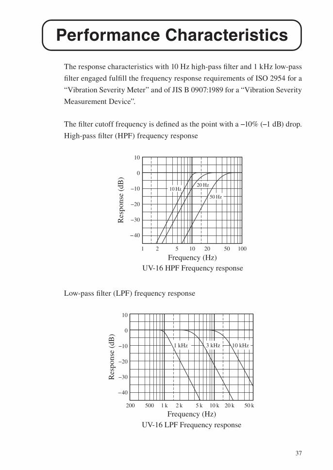
Performance Characteristics
The response characteristics with 10 Hz high-pass fi lter and 1 kHz low-pass
fi lter engaged fulfi ll the frequency response requirements of ISO 2954 for a
“Vibration Severity Meter” and of JIS B 0907:1989 for a “Vibration Severity
Measurement Device”.
The fi lter cutoff frequency is defi ned as the point with a −10% (−1 dB) drop.
High-pass fi lter (HPF) frequency response
Low-pass fi lter (LPF) frequency response
10 Hz20 Hz
50 Hz
10
0
−10
−20
−30
−40
1 2 5 10 20 50 100
UV-16 HPF Frequency response
Res
pons
e (d
B)
Frequency (Hz)
1 kHz 3 kHz 10 kHz
10
0
−10
−20
−30
−40
200 500 1 k 2 k 5 k 10 k 20 k 50 k
UV-16 LPF Frequency response
Res
pons
e (d
B)
Frequency (Hz)
38
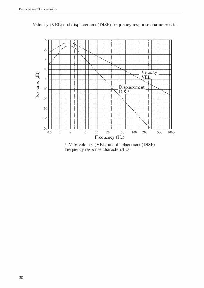
Performance Characteristics
Velocity (VEL) and displacement (DISP) frequency response characteristics
40
30
20
10
0
−10
−20
−30
−40
−500.5 1 2 5 10 20 50 100 200 500 1000
UV-16 velocity (VEL) and displacement (DISP)frequency response characteristics
VelocityVEL
Res
pons
e (d
B)
Frequency (Hz)
DisplacementDISP

39
Specifi cations
Applicable standards CE marking, UKCA marking, China RoHS
Input
Number of channels 2
Connector type Microdot connectors
Supported accelerometers
Piezoelectric accelerometer
Accelerometer with integrated preamplifi er, 24 V 4 mA
Measurement modes and units
Acceleration/velocity/displacement, selectable
ACC (acceleration): m/s2
VEL (velocity): mm/s
DISP (displacement): mm
Sensitivity setting
Setting range 0.100 to 0.999 in 0.001 steps
1.00 to 9.99 in 0.01 steps
10.0 to 99.9 in 0.1 steps
Units pC/(m/s2) (using piezoelectric accelerometer)
mV/(m/s2) (using accelerometer with integrated pre-
amplifi er)
Range
Seven stages Sensitivity setting determines range.
Sensitivity setting 0.100 to 0.999
ACC (acceleration): 10, 30, 100, 300, 1000, 3000, 10000
VEL (velocity): 10, 30, 100, 300, 1000, 3000, 10000
DISP (displacement): 1, 3, 10, 30, 100, 300, 1000
Sensitivity setting 1.00 to 9.99
ACC (acceleration): 1, 3, 10, 30, 100, 300, 1000
VEL (velocity): 1, 3, 10, 30, 100, 300, 1000
DISP (displacement): 0.1, 0.3, 1, 3, 10, 30, 100
40
Specifi cations
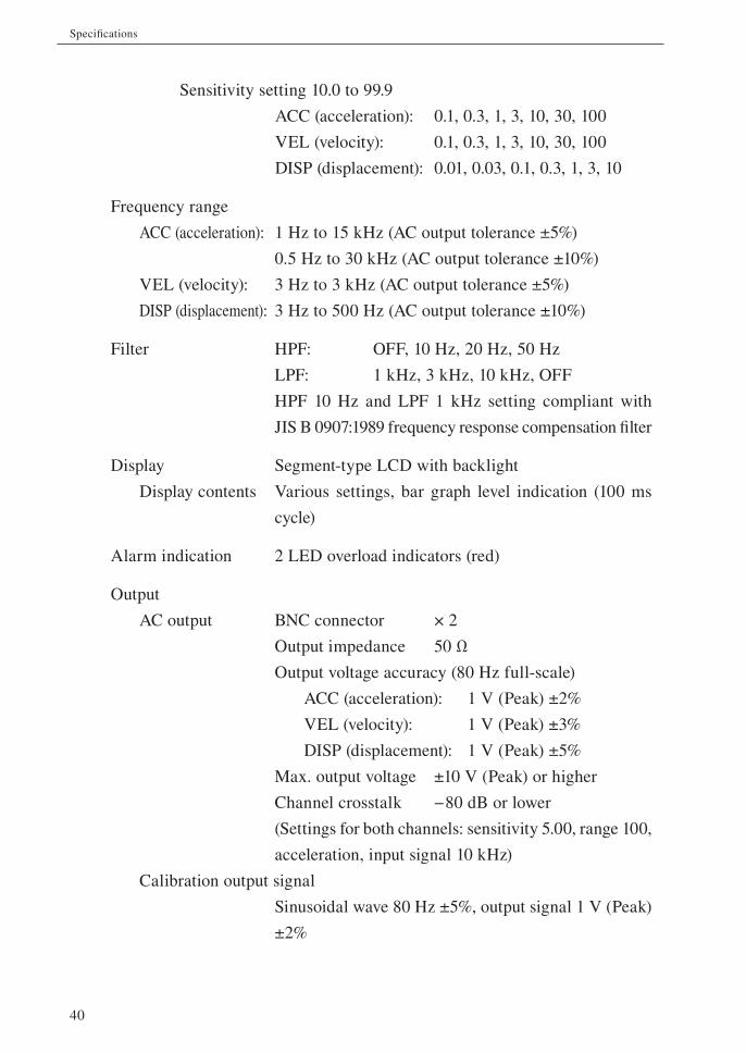
Sensitivity setting 10.0 to 99.9
ACC (acceleration): 0.1, 0.3, 1, 3, 10, 30, 100
VEL (velocity): 0.1, 0.3, 1, 3, 10, 30, 100
DISP (displacement): 0.01, 0.03, 0.1, 0.3, 1, 3, 10
Frequency range
ACC (acceleration): 1 Hz to 15 kHz (AC output tolerance ±5%)
0.5 Hz to 30 kHz (AC output tolerance ±10%)
VEL (velocity): 3 Hz to 3 kHz (AC output tolerance ±5%)
DISP (displacement): 3 Hz to 500 Hz (AC output tolerance ±10%)
Filter HPF: OFF, 10 Hz, 20 Hz, 50 Hz
LPF: 1 kHz, 3 kHz, 10 kHz, OFF
HPF 10 Hz and LPF 1 kHz setting compliant with
JIS B 0907:1989 frequency response compensation fi lter
Display Segment-type LCD with backlight
Display contents Various settings, bar graph level indication (100 ms
cycle)
Alarm indication 2 LED overload indicators (red)
Output
AC output BNC connector × 2
Output impedance 50 Ω
Output voltage accuracy (80 Hz full-scale)
ACC (acceleration): 1 V (Peak) ±2%
VEL (velocity): 1 V (Peak) ±3%
DISP (displacement): 1 V (Peak) ±5%
Max. output voltage ±10 V (Peak) or higher
Channel crosstalk −80 dB or lower
(Settings for both channels: sensitivity 5.00, range 100,
acceleration, input signal 10 kHz)
Calibration output signal
Sinusoidal wave 80 Hz ±5%, output signal 1 V (Peak)
±2%
41
Specifi cations
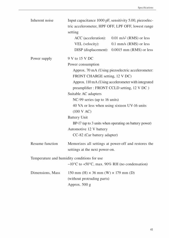
Inherent noise Input capacitance 1000 pF, sensitivity 5.00, piezoelec-
tric accelerometer, HPF OFF, LPF OFF, lowest range
setting
ACC (acceleration): 0.01 m/s2 (RMS) or less
VEL (velocity): 0.1 mm/s (RMS) or less
DISP (displacement): 0.0015 mm (RMS) or less
Power supply 9 V to 15 V DC
Power consumption
Approx. 70 mA (Using piezoelectric accelerometer:
FRONT CHARGE setting, 12 V DC)
Approx. 110 mA (Using accelerometer with integrated
preamplifi er : FRONT CCLD setting, 12 V DC )
Suitable AC adapters
NC-99 series (up to 16 units)
40 VA or less when using sixteen UV-16 units
(100 V AC)
Battery Unit
BP-17 (up to 3 units when operating on battery power)
Automotive 12 V battery
CC-82 (Car battery adapter)
Resume function Memorizes all settings at power-off and restores the
settings at the next power-on.
Temperature and humidity conditions for use
−10°C to +50°C, max. 90% RH (no condensation)
Dimensions, Mass 150 mm (H) × 36 mm (W) × 179 mm (D)
(without protruding parts)
Approx. 500 g
42
Specifi cations
Supplied accessories
Instruction manual 1
Link plate 1
Inspection certifi cate 1
Optional accessories
AC adapter NC-99 series (up to 16 units)
Battery Unit BP-17
BNC-BNC cable NC-39A
Piezoelectric accelerometer Various
Connection cable Various
Rack Mounting Base CF-27
Car battery adapter CC-82
43
Specifi cations
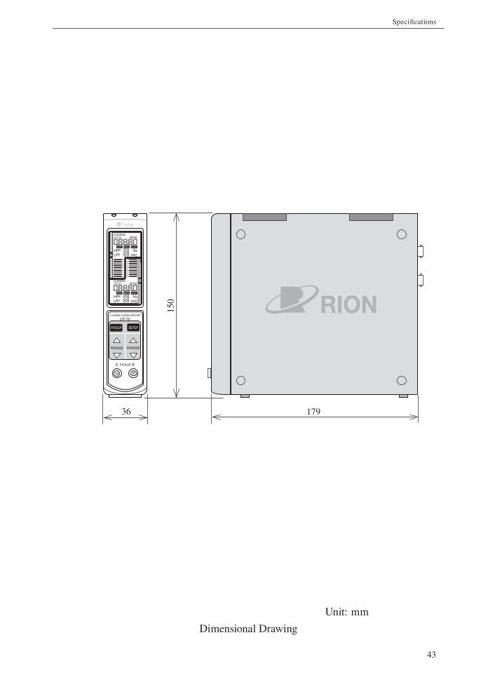
Unit: mm
Dimensional Drawing
CHARGECCLD SENS
m/s2 mm/s mm
HzkHz
CHARGECCLD SENS
m/s2 mm/s mm
HPFLPF
HzkHz
HPFLPFA
B
A PICKUP B
2 CHANNEL CHARGE AMPLIFIER
UV-16
PICKUP SETUP
RANGE RANGE
36
150
179
44
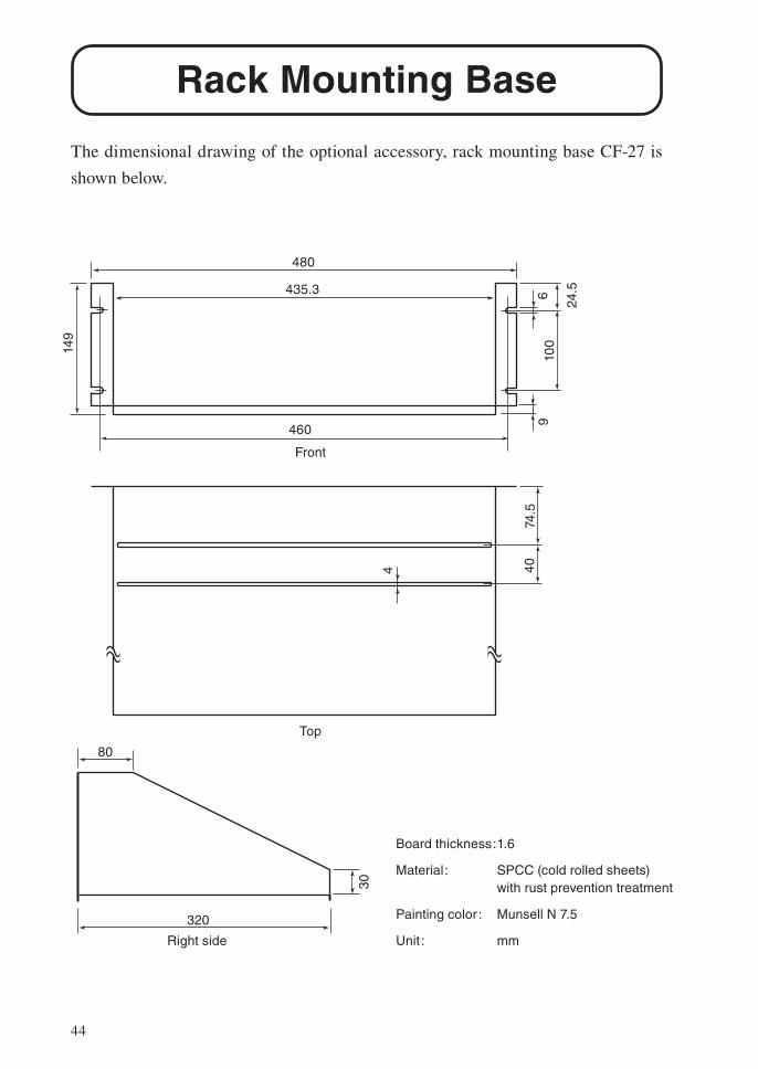
Rack Mounting Base
The dimensional drawing of the optional accessory, rack mounting base CF-27 is
shown below.
480
435.3
460
149
100
69
24.5
80
320
30
Front
Right side
Board thickness: 1.6
Material: SPCC (cold rolled sheets) with rust prevention treatment
Painting color : Munsell N 7.5
Unit : mm
74.5
404
Top
45
Reference Material
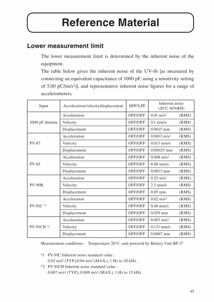
Lower measurement limit
The lower measurement limit is determined by the inherent noise of the
equipment.
The table below gives the inherent noise of the UV-16 [as measured by
connecting an equivalent capacitance of 1000 pF, using a sensitivity setting
of 5.00 pC/(m/s2)], and representative inherent noise fi gures for a range of
accelerometers.
Input Acceleration/velocity/displacement HPF/LPFInherent noise
(20°C 40%RH)
1000 pF dummy
Acceleration OFF/OFF 0.01 m/s2 (RMS)
Velocity OFF/OFF 0.1 mm/s (RMS)
Displacement OFF/OFF 0.0015 mm (RMS)
PV-87
Acceleration OFF/OFF 0.0013 m/s2 (RMS)
Velocity OFF/OFF 0.013 mm/s (RMS)
Displacement OFF/OFF 0.00025 mm (RMS)
PV-85
Acceleration OFF/OFF 0.008 m/s2 (RMS)
Velocity OFF/OFF 0.08 mm/s (RMS)
Displacement OFF/OFF 0.0013 mm (RMS)
PV-90B
Acceleration OFF/OFF 0.25 m/s2 (RMS)
Velocity OFF/OFF 2.5 mm/s (RMS)
Displacement OFF/OFF 0.05 mm (RMS)
PV-91C *1
Acceleration OFF/OFF 0.02 m/s2 (RMS)
Velocity OFF/OFF 0.48 mm/s (RMS)
Displacement OFF/OFF 0.029 mm (RMS)
PV-91CH *2
Acceleration OFF/OFF 0.007 m/s2 (RMS)
Velocity OFF/OFF 0.133 mm/s (RMS)
Displacement OFF/OFF 0.0067 mm (RMS)
Measurement conditions: Temperature 20°C, unit powered by Battery Unit BP-17
*1 PV-91C Inherent noise standard value :
0.02 m/s2 (TYP.),0.04 m/s2 (MAX.), 1 Hz to 20 kHz.
*2 PV-91CH Inherent noise standard value :
0.007 m/s2 (TYP.), 0.009 m/s2 (MAX.), 1 Hz to 15 kHz.
46
Reference Material
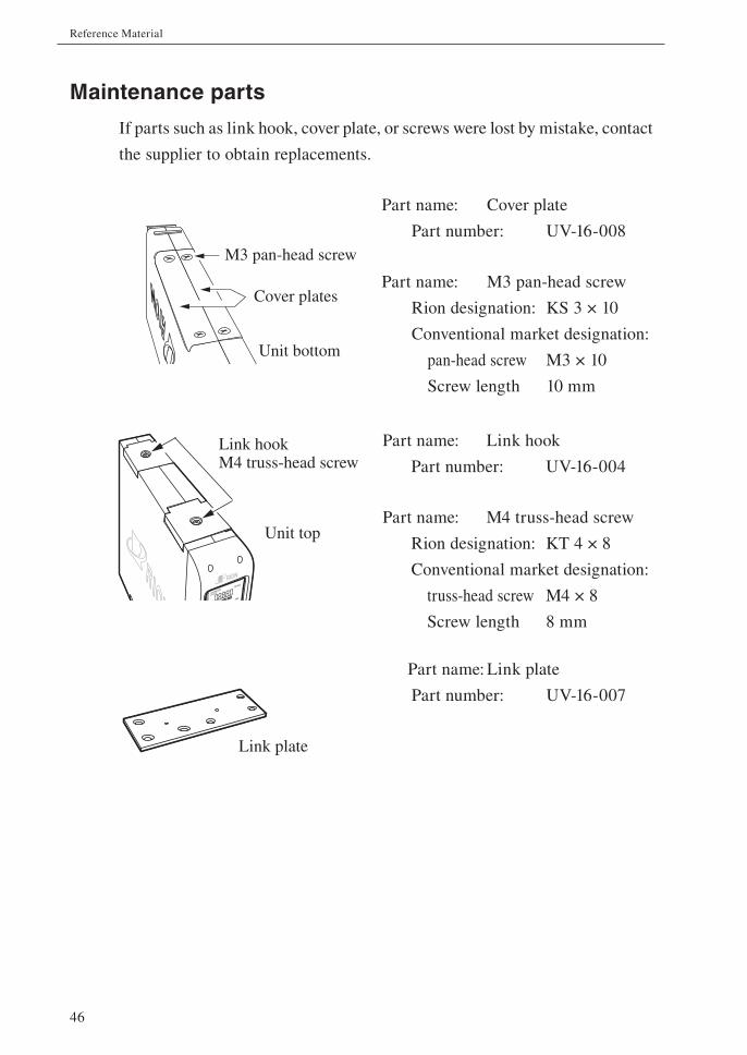
Maintenance parts
If parts such as link hook, cover plate, or screws were lost by mistake, contact
the supplier to obtain replacements.
Part name: Cover plate
Part number: UV-16-008
Part name: M3 pan-head screw
Rion designation: KS 3 × 10
Conventional market designation:
pan-head screw M3 × 10
Screw length 10 mm
Part name: Link hook
Part number: UV-16-004
Part name: M4 truss-head screw
Rion designation: KT 4 × 8
Conventional market designation:
truss-head screw M4 × 8
Screw length 8 mm
Part name: Link plate
Part number: UV-16-007
Unit bottom
M3 pan-head screw
Cover plates
Link plate
CHARGE
CCLD
SENS
mm/s mm Hz
Unit top
Link hookM4 truss-head screw


No. 65790 21-11