Embed Size (px)
Citation preview
www.jisrf.org • Joint Implant Surgery & Research Foundation
Reconstructive ReviewVolume 4, Number 1, March 2014
IntroductionCarbon fiber (CF) offers many unique physical, chemi-
cal and biological characteristics that can be exploited for many diverse applications. CF components can be found in aerospace systems, structural elements in civil engineering projects, automotive components, lighting filaments, ener-gy production systems, power transmission systems, ener-gy storage, sporting goods and recently, their use has ex-panded into the surgical implant space.
Material Properties of CFCF offers many unique physical and chemical proper-
ties to include high heat tolerance, high strength to weight ratio, resistance to corrosion, & conductivity.
One measure of stiffness is modulus of elasticityElastic modulus = stress/strainModulus is measured in units of pressure such as Pascal
or pounds per square inch (PSI). It is typical for large mea-surements to be listed as thousands or millions KSI and MSI respectively. The modulus of carbon fiber is normal-ly 20 MSI, significantly greater than comparable materials such as 2024-T3 aluminum or steel, which have moduli of 10 and 30 MSI respectively. [1]
§ Nevada Orthopedic and Spine Center 2650 North Tenaya Way, Suite 301, Las Vegas, NV 89128 † Touro University Nevada, College of Osteopathic Medicine 874 American Pacific Drive, Henderson, NV 89014
Utility of Carbon Fiber Implants in Orthopedic Surgery: Literature Review
Ronald Hillock, MD§, Shain Howard, BS†
Abstract
Carbon fiber (CF) consists of a multitude of unique physical, chemical and biological characteris-tics that can be utilized and exploited for a number of diverse applications. Found in aerospace systems, structural elements, energy storage and other products, the most recent application of CF has expanded into the realm of surgical implants. The material properties of CF, historical development and applica-tions and methods of manufacturing are illustrated upon. The various surgical applications of CF are de-fined, from biocompatibility within the human body and wound healing products to numerous surgical implantations. Keywords: carbon fiber; orthopedics; historical review
The tensile strength of CF is greater than comparable metallic materials. The ultimate tensile strength of CF is 500 KSI, significantly stronger than 2024-T3 aluminum 65 KSI or steel 125 KSI. The added advantage of a lower den-sity than comparable materials is responsible for the in-creased strength to weight ratio. The strength of CF devic-es is further augmented by the layout and orientation of the carbon fibers and the ratio of CF to polymer, like carbon fiber reinforced polymer (CFRP), which is comprised of a combination of CF and polyethylene. CF materials gener-ally have an increase in tensile strength and stiffness when layers of CF fibers embedded in polymer are oriented at different angles. [2]
Of note it is difficult to compare CF to metallic devic-es for endurance limits, as CF does not have a definable endurance limit. A lack of a predictable stress cycle fail-ure makes engineering calculations more difficult. This is overcome by allowing a greater margin than would typi-cally be used with non-CF structural materials. [2]
H I S T O R I C A L R E V I E W
Copyright 2014, JISRF. All rights reserved.JISRF gives permission for reproduction of articles as long as notification and recognition is provided.
24 JISRF Reconstructive Review • Vol. 4, No. 1, March 2014
Joint Implant Surgery & Research Foundation • www.jisrf.org
Historical Development and Industrial Application of CF
The first commercial application of CF was in the fila-ments of the light bulb in 1879. The first industrial enter-prise dedicated to the use and manufacture of CF materi-als was the National Carbon Company in Cleveland, Ohio, established 1886. The physical and chemical properties of CF were studied in detail and published in 1956 by R Ba-con of the Parma Technical Center [3]. Bacon later went on the develop CF nanotubules, small segments of CF fila-ment that resume their original shape and orientation in the face of mechanical deformation. Nanotubules have been shown to be the strongest material per mass ever fabricat-ed by humans.
Later developments in CF applications came in the 1960s with the development of the process known as “hot stretching.” [4] When heated to extremely high tempera-tures, CF could be molded and pulled into a carbon yarn that could be formed into heat resistant components. The aerospace industry was then able to exploit this feature in the fabrication rocket nozzles, missile protective tip cov-ers, heat resistant gaskets, heat-resistant aircraft structur-al members and spacecraft heat shields. When compared to metallic devices, CF offered reduced mass, increased strength and increased heat resistance. CF materials were ideal for aerospace applications allowing for the creation of more novel vehicles with increased performance charac-teristics as well as savings in fuel consumption.
Further advances in CF materials came out via the ad-dition of polyacrylonitirel (PAN). [5] The combination of PAN with CF created a material with a higher modulus of elasticity and heat resistance. PAN-based CF materials have further expanded applications in aerospace, civil en-gineering and electric storage lithium batteries.
The next wave of CF production technology came by taking advantage of petroleum and coal based starting ma-terials that were heated to produce “pitch.. While heat-ing the precursor material purifies its carbon content and gives the structure order, precursors differ in their ability to approach perfect graphite structure on heating. Pitch ap-proaches a level of order closer to perfect graphite crystal than either PAN or rayon. With higher carbon content and the ability to align and layer the molecules, pitch based CF had a higher elastic modulus and became the first car-bon fibers to have very high thermal conductivity. With more perfect CF filaments, the material could then be used in electronic circuits and high performance aircraft brake pads.
Other teams also working with PAN-based CF in the 1960s developed a low modulus PAN fiber with a very
high tensile strength that went on to become the materi-al widely used in sporting goods applications, golf clubs, snow and water skis, as well as baseball bats (2013).
Industrial Corporate Evolution of CF Applications
Union Carbides main CF division was eventually sold to Amoco, later then acquired by Cytec Industries. With its headquarters in New Jersey and 5,800 employees world-wide, Cytec continues to deliver both pitch and PAN based CF products. Its earnings are up 64% compared to the pri-or year quarter; second quarter 2013 sales are $514 million, and the significant increase in earnings per share (EPS) are largely attributed to their aerospace materials division. [6] The United States Department of Energy (DOE) has also been seeking to develop CF applications. Oak Ridge Na-tional Laboratory in Tennessee, the largest science and en-ergy laboratory in the DOE, has been working toward a lower cost CF production and application project with the goal of making CF more accessible for the benefit of indus-try and the economy. [7]
In Japan, Toray Industries focused on synthetic chemis-try and biochemistry in order to expand its scope of busi-ness to include fibers, textiles, plastics, and pharmaceu-ticals. It is currently the world’s largest producer of CF. Among the many customers of Toray Industries, the Boe-ing Company has taken advantage of the properties of CF in the production of lighter more efficient aircraft. The Boeing 787 Dreamliner is the company’s latest and most fuel-efficient airliner. This twin engine, 210–330 passen-ger jet airliner is mostly composite material, with CFRP accounting for 50% of its material. [8]
Another aircraft whose design takes advantage of the unique features of CF is the United States Air Force F-22A Raptor air superiority jet fighter. [9] The Raptor was designed to be a more agile, stealthy, and longer range re-placement for the aging fleet of F-15’s. The Raptor can cruise at speeds over Mach 1.5 without using an afterburn-er. The Raptor is built from 24% composite other than met-al materials, with CF composite components used in the fuselage frame, doors, and wing structural elements.
CF has also led the revolution of speed and performance on the ground. The McLaren Formula One racecar was the first to use a CF composite monocoque, which describes a system where a vehicle is supported by its external surfac-es. [10] Since then, CF has become widely used in auto-motive monocoque assemblies. CF elements can be found in NASCAR vehicle exterior components, and both the in-terior and exterior of many of the world’s finest supercars.
www.jisrf.org • Joint Implant Surgery & Research Foundation
Utility of Carbon Fiber Implants in Orthopedic Surgery: Literature Review 25
Ferrari’s latest offering, the F70, has a body and frame that is largely fabricated from CF materials as a weight reduc-tion measure, greatly enhancing performance while reduc-ing mass. [11]
A less exotic use of CF technology that is becoming in-creasingly common can be found in civil engineering ap-plications for both new structures and reinforcement of existing structures. One example is CFRP used in the re-inforcement of bridges for both flexural and shear applica-tions. The mechanism of flexural improvement has been shown to be through increasing fatigue life by reducing the magnitude of steel stress when used to reinforce girders, which are structural beams. [1]
Published studies have investigated the effects of CFRP on shear resistance. One such study investigated the use of L-shaped CFRP plates on a shear deficient concrete struc-ture. The L-shaped CFRP plates used were not damaged after 5 million cycles at a load equal to 59% of failure load. The eventual mode of failure was crushing of the concrete after the internal flexural reinforcement gave way. [12]
The Oregon Department of Transportation has put a sig-nificant amount of research into shear stress strengthening as it relates to CF. Their results show a significant increase in load capacity and stiffness in CFRP repaired beams. This improvement was maintained, even after being ex-posed to the equivalent of twenty years of traffic induced fatigue. These findings have lead to many US States and Canadian Provinces adopting CFRP members in bridge re-inforcement projects. [1]
Manufacturing
Although historically rayon had been used in the pro-duction of CF, two main precursors are used today. One is based on pitch while the other is based on PAN; with each having it’s own unique set of properties.
Pitch fibers have larger crystal size, higher modulus/stiffness, and higher electrical & thermal conductivity. The University of Tennessee Space Institute (UTSI) is current-ly researching and producing pitch-based CF production. The process involves selecting a pitch with adequate soft-ening point temperature then passing it through a spinning device. After being cooled from liquid to solid, the fibers undergo the rate-limiting (cost and time) step of oxidative stabilization. The final step is carbonization or graphitiza-tion, where the product is heated in a solution to dissolve and remove any residual non-CF contamination.
PAN fibers are the most commonly used CF. They are expensive to produce, have small crystals, high tensile strength, good flexibility, and good electrical conductivity.
PAN fibers are made by stretching, heating, and oxidizing PAN precursor filaments. Carbonization at very high tem-peratures (1200°C) in a nitrogen atmosphere purifies the carbon content.
There are a few different ways of making CF rein-forced products (molding, compression molding, filament winding, & vacuum bagging) from these precursors. With each of these methods, the directional CF are layered per-pendicular to one another and some type of resin is added. The resin/reinforcement used determines the name and the properties of each carbon fiber type. [13]
A few examples are:• CFRP – carbon fiber reinforced plastic• CRP – carbon reinforced plastic• CFRTP - carbon fiber reinforced thermoplastic• CF-PEEK – carbon fiber polyether ether ketoneHybrid fabrics such as carbon-Kevlar can also be pro-
duced. [14] This protects and enhances the properties of carbon fiber leading to a very high tensile strength, high impact, and abrasive resistant product. This has been used the fabrication of combat helmets, composite armor re-inforcement, penetration resistant body armor garments, ropes, and cables.
Manufacturers such as FiberForge™ have reduced the explanation of the process to 4 simple steps: layup, con-solidation, forming, & trimming. [15] The process and ma-chinery allows for reduced production time, while allow-ing customization of CF products and forms.
CF materials are expensive when compared to similar metallic elements on a unit mass basis. Excess CF mate-rials can’t be recycled and simply melted down, as is the standard in metal device manufacturing. Recycled CF ma-terial leads to reduced fiber lengths. Some applications do not need long CF strands such as laptop computers and other electronic devices. This can be done when the waste CF materials do not contain toxins such as halogenated polymers (e.g., PVC).
Medical Application of CF Materials
Advances in the manufacture of carbon fiber have al-lowed large-scale production of a more diverse array of carbon fiber composites. As in other industries, its physi-cal properties have lead to many innovations in medical implants and devices. CF medical applications range from dental orthodontics to medical limb prosthetic fabrication; literally from head to toe examples are now found on the market.
26 JISRF Reconstructive Review • Vol. 4, No. 1, March 2014
Joint Implant Surgery & Research Foundation • www.jisrf.org
Wound Healing ProductsA bilayer wound dressing developed in 2012 has shown
to accelerate wound healing. An oxidized PAN-CF cloth has been used as the starting base material in wound dress-ings. This PAN-CF cloth was treated with phosphoric acid and steamed at high temperatures to activate it before add-ing a gentamycin gelatin membrane. Follow up exami-nation of wounds treated with this device at days 2, 4, 8, and 12 after surgery in 24 specimens showed the bilayer dressing acted as a scaffold in wound healing. This scaf-fold promoted fibroblast growth and migration, leading to up-regulation of fibronectin and type I collagen, which was theorized to have allowed for accelerated wound healing and closure. [16]
BiocomPatiBilityCarbon fiber reinforced PEEK (CF-PEEK) has good
mechanical properties, high resistance to ionizing radia-tion, and lower wear than comparable materials like ul-tra high molecular weight polyethylene (UHMWPE). A 2010 study compared the inflammatory response of CF-PEEK pitch, CF-PEEK PAN, and UHMWPE. Wear par-ticles from each of these materials were injected into the left knee of 50 rats. Fluorescence microscopy and subse-quent (7 days later) histological analysis were used to as-sess synovial microcirculation and leukocyte-endotheli-al cell interaction as measures of inflammatory reaction. Results indicated no significant difference in inflammatory response generated by each of the particle types, therefore both types of carbon fiber are theorized to be potential al-ternatives to UHMWPE as bearing materials in arthroplas-ty. [17]
CF has increased strength and stiffness with better fa-tigue and wear resistance than comparable metal alloys such as titanium. It also has an elastic modulus much clos-er to that of bone and is radiolucent, all of which make it a favorable implant biomaterial. Establishment of these strengths has allowed research to focus on its few biocom-patibility limitations, which include its bio-inert and hy-drophobic properties. A 2010 study examined the use of Diamond-like carbon (DLC) as a coating for PEEK. Plas-ma immersion ion implantation and deposition was used to coat 5x3 mm samples of PEEK. The structure and surface were then analyzed with atomic force microscopy, X-ray photoelectron spectroscopy, and Raman spectroscopy. The hydrophilic nature of CF was assessed with static contact angle measurement by the sessile drop method on a ramé-hart instrument. Hardness and elastic modulus were mea-sured by nanoindentation. Finally, human fetal osteoblast cell lines and rat calvaria-derived osteoblast were used to assess the DLC-coated PEEK. Cell viability, scanning
electron microscopy, and real-time PCR showed that os-teoblast attachment, proliferation, and differentiation were better on DLC-PEEK. [18]
A review of the published literature will show that no cases of allergic reaction to CF implants have ever been re-ported in animal models or clinical applications in human subjects. No known hypersensitivity response has ever been documented in CF implant application.
Specific Clinical Applications of CF Implants
craniumCF-PEEK reinforced implants made by stereolithogra-
phy have shown to be effective in cranioplasty. Between 1996 and 2002, 41 CF-PEEK implants created by stereo-lithography from helical CT were performed on 37 pa-tients with large/complex cranial defects. 21 of these cases had frontal sinus involvement, a recognized risk factor for complications. Excellent results were attained in 87.8% of these cases. [19]
maxillofacialIn the field of orthodontics, CF has recently been com-
pared to other commonly used materials. In 2011, fifty hu-man incisors were cut and prepared with each of the fol-lowing types of posts: serrated titanium, CF reinforced, individually formed glass fiber reinforced (GFR), and in-dividually formed split-GFR. Intact human incisors were used as the control. Stiffness was measured by micro-strain, using the strain gage technique. Load bearing ca-pacity was measured using a static load applied at forty-five degrees on the palatal side. Fractures that extended from the load-bearing site, across the incisor, and below the margin of stimulated bone were considered unfavor-able. The intact group had the highest initial fracture load, while the titanium group had the highest number of unfa-vorable fractures. The composite groups showed a compa-rable load bearing capacity with a lower number of unfa-vorable fractures. The favorable fractures of the composite group have the advantage of being clinically repairable. [20]
cervical sPineMultiple studies have shown the use of CF cages at
the cervical spine. One study followed 97 patients suf-fering from myeloradiculopathy caused by spondylodis-carthrosis, simple disc herniation, or posttraumatic disc herniation. These 52 males & 45 females received microd-iscectomy followed by inter-body fusion with CF cage sta-bilization, with only 10 cases requiring anterior plates. Of
www.jisrf.org • Joint Implant Surgery & Research Foundation
Utility of Carbon Fiber Implants in Orthopedic Surgery: Literature Review 27
the 91 patients that were followed to end state, there were no cases of spontaneous implant displacement, persistence of nerve compression symptoms, or change in interverte-bral height. [21]
The use of cervical CF cages has also been compared to the Smith-Robinson technique. The traditional method of a Smith-Robinson cervical fusion is through the use of autologous tricortical iliac crest placed into the disc space. One study divided 40 patients with degenerative disc dis-ease or refractory cervicalgia with radiculopathy into two groups. Half of the patients received a CF cage with iliac crest cancellous autograft. 19 patients of the second group received DePuy hardware and the last patient received CF-PEEK, all with unicortical locking expansion screws. After randomization, there was no significant difference between the two groups, indicating that in addition to the reduc-ing graft site pain, the CF cages were an acceptable alter-native to the classically performed Smith-Robinson tech-nique. [22]
lumBar sPineCF has also proven to be a very effective material in
the lumbar spine implant applications. A two-year prospec-tive study of 46 patients with isthmic or degenerative spon-dylolisthesis helped establish its use. This group of 21-75 year old patients had symptomatic spondylolisthesis at a single level below L4 with greater than 3 mm translational misalignment. The results of increased fusion, increased function, decreased pain, and decreased complications are extremely positive. [23]
sPine imagingThe strength of CF in spinal procedures is further bol-
stered by studies highlighting the radiological advantages as compared to the metal products that have been classi-cally used. One of such studies compared carbon, titani-um, and cobalt-chrome with the control of human cortical bone. This cadaveric study used a 1.5T MRI, focusing on 12 regions of interest, which were used to create a twen-ty-four point scoring system to evaluate the “distinguish-ability” of each sample. Cobalt-chromium ranked 50%, ti-tanium ranked 62.5%, and carbon ranked the highest with 83.3%. Carbon allowed superior evaluation of local im-plant situation and pathological process while maintaining a lower susceptibility to cause image artifact. [24]
HumerusAlthough many of the previously discussed properties
of CF products have been characterized in studies since the early eighties, a 2012 study of CF-PEEK Optima (Pic-colo™ system) further validated their use in orthopedic
traum. [25] Among the CF-PEEK products evaluated was a proximal humeral plate (PHP), which was tested for four-point bending, static torsion, bending fatigue, and wear. Results showed the PHP to be sufficient for humeral frac-ture fixation. [26]
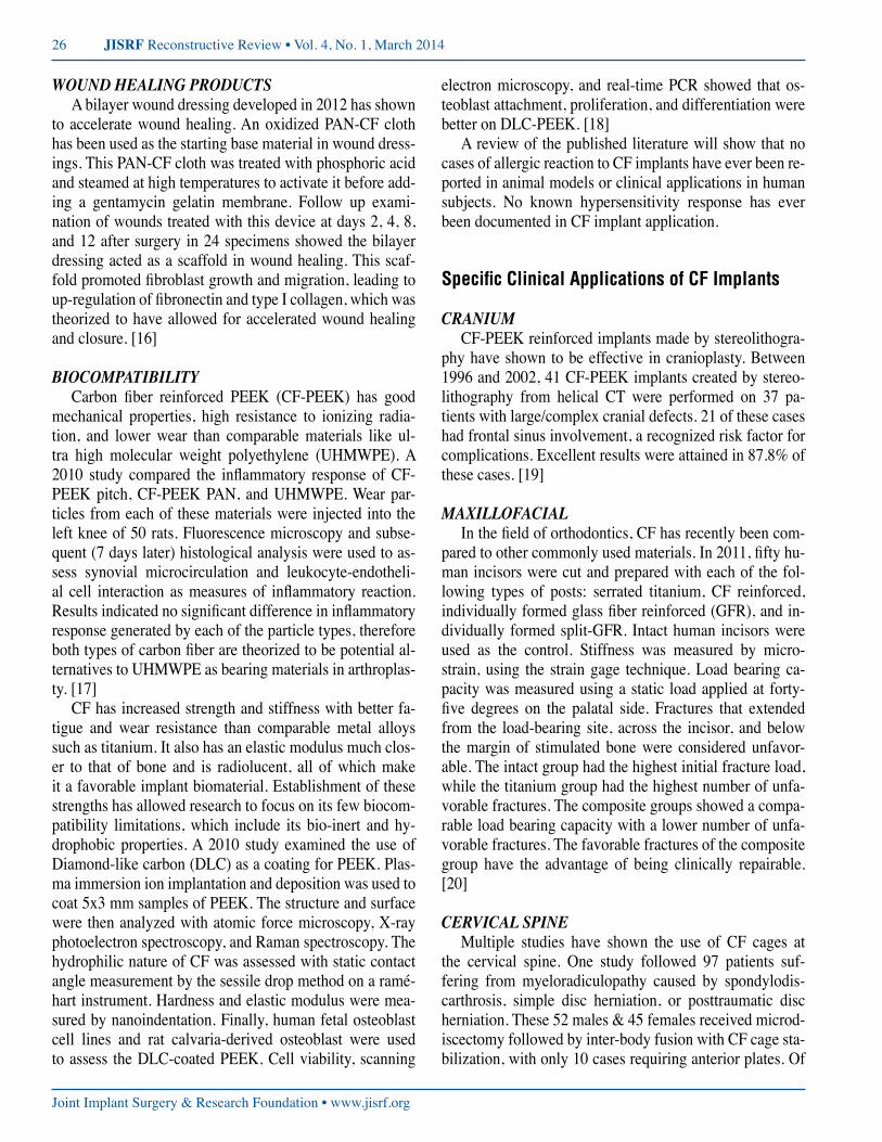
The Piccolo™ system is Manufactured and Marketed by Carbo-Fix™, in Herzeliya, Israel. [25] The low profile PHP has suture holes on the proximal end of the plate, al-lowing for the use of K-wires for provisional fixation or suture eyelets for use of suture stabilization in osteoporot-ic bone. The Carbo-Fix™ PHP takes advantage of 3.5 mm proximal humeral head fixed angle threaded locking holes
for use with 3.5 mm titanium locking screws. There are 3 different sizes currently marketed in both left and right configurations. The shaft screw holes can be used in either a locking or non-locking mode. The radiolucent design al-lows for radiographic visualization of the fracture reduc-tion while a thin embedded metallic/radiopaque outline at delineating the implant’s edges for visualization during in-sertion and later follow up images. The PHP has been used successfully in trauma as well as oncologic applications since its introduction. [26]
A large fragment 4.5 mm CF-PEEK plate system is
figure 1: CarboFix™ proximal humerus plating system with aiming guide attached (A) and with locking and nonlocking screw options in place (B). Images reproduced with the expressed permission of CarboFix Orthopedics Ltd. 11 Ha’hoshlim St., Herzeliya 46724, Israel.
A.
A.
B.
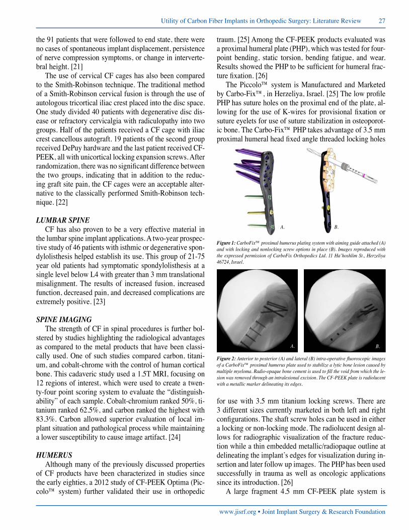
figure 2: Anterior to posterior (A) and lateral (B) intra-operative fluoroscopic images of a CarboFix™ proximal humerus plate used to stabilize a lytic bone lesion caused by multiple myeloma. Radio-opaque bone cement is used to fill the void from which the le-sion was removed through an intralesional excision. The CF-PEEK plate is radiolucent with a metallic marker delineating its edges.
B.
28 JISRF Reconstructive Review • Vol. 4, No. 1, March 2014
Joint Implant Surgery & Research Foundation • www.jisrf.org
now manufactured and marketed by Carbo-Fix™. [25] The large fragment plates come in both narrow and broad locking plate designs, analogous to the metallic large frag-ment systems produced by many implant vendors. The CF-PEEK large fragment screws are available in both threaded 4.5 mm locking and 4.5 mm nonlocking titanium options. Molding and contouring of these plates requires the use of a heating device, partially melting the CF-PEEK plate to melting point and then holding the plate while it cools and hardens. No studies have been published on the use of
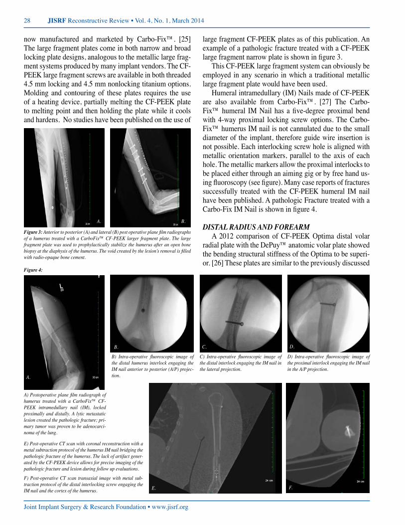
large fragment CF-PEEK plates as of this publication. An example of a pathologic fracture treated with a CF-PEEK large fragment narrow plate is shown in figure 3.
This CF-PEEK large fragment system can obviously be employed in any scenario in which a traditional metallic large fragment plate would have been used.
Humeral intramedullary (IM) Nails made of CF-PEEK are also available from Carbo-Fix™. [27] The Carbo-Fix™ humeral IM Nail has a five-degree proximal bend with 4-way proximal locking screw options. The Carbo-Fix™ humerus IM nail is not cannulated due to the small diameter of the implant, therefore guide wire insertion is not possible. Each interlocking screw hole is aligned with metallic orientation markers, parallel to the axis of each hole. The metallic markers allow the proximal interlocks to be placed either through an aiming gig or by free hand us-ing fluoroscopy (see figure). Many case reports of fractures successfully treated with the CF-PEEK humeral IM nail have been published. A pathologic Fracture treated with a Carbo-Fix IM Nail is shown in figure 4.
distal radius and forearmA 2012 comparison of CF-PEEK Optima distal volar
radial plate with the DePuy™ anatomic volar plate showed the bending structural stiffness of the Optima to be superi-or. [26] These plates are similar to the previously discussed
A. B.
figure 3: Anterior to posterior (A) and lateral (B) post operative plane film radiographs of a humerus treated with a CarboFix™ CF-PEEK larger fragment plate. The large fragment plate was used to prophylactically stabilize the humerus after an open bone biopsy at the diaphysis of the humerus. The void created by the lesion’s removal is filled with radio-opaque bone cement.
figure 4:
A.
C.
F.
D.
E.
B.
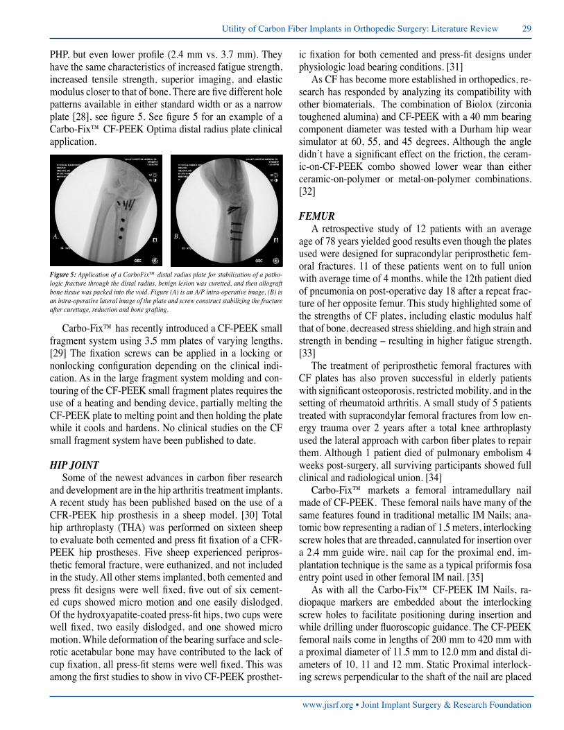
A) Postoperative plane film radiograph of humerus treated with a CarboFix™ CF-PEEK intramedullary nail (IM), locked proximally and distally. A lytic metastatic lesion created the pathologic fracture; pri-mary tumor was proven to be adenocarci-noma of the lung.
B) Intra-operative fluoroscopic image of the distal humerus interlock engaging the IM nail anterior to posterior (A/P) projec-tion.
C) Intra-operative fluoroscopic image of the distal interlock engaging the IM nail in the lateral projection.
D) Intra-operative fluoroscopic image of the proximal interlock engaging the IM nail in the A/P projection.
E) Post-operative CT scan with coronal reconstruction with a metal subtraction protocol of the humerus IM nail bridging the pathologic fracture of the humerus. The lack of artifact gener-ated by the CF-PEEK device allows for precise imaging of the pathologic fracture and lesion during follow up evaluations.
F) Post-operative CT scan transaxial image with metal sub-traction protocol of the distal interlocking screw engaging the IM nail and the cortex of the humerus.
www.jisrf.org • Joint Implant Surgery & Research Foundation
Utility of Carbon Fiber Implants in Orthopedic Surgery: Literature Review 29
PHP, but even lower profile (2.4 mm vs. 3.7 mm). They have the same characteristics of increased fatigue strength, increased tensile strength, superior imaging, and elastic modulus closer to that of bone. There are five different hole patterns available in either standard width or as a narrow plate [28], see figure 5. See figure 5 for an example of a Carbo-Fix™ CF-PEEK Optima distal radius plate clinical application.
Carbo-Fix™ has recently introduced a CF-PEEK small fragment system using 3.5 mm plates of varying lengths. [29] The fixation screws can be applied in a locking or nonlocking configuration depending on the clinical indi-cation. As in the large fragment system molding and con-touring of the CF-PEEK small fragment plates requires the use of a heating and bending device, partially melting the CF-PEEK plate to melting point and then holding the plate while it cools and hardens. No clinical studies on the CF small fragment system have been published to date.
HiP JointSome of the newest advances in carbon fiber research
and development are in the hip arthritis treatment implants. A recent study has been published based on the use of a CFR-PEEK hip prosthesis in a sheep model. [30] Total hip arthroplasty (THA) was performed on sixteen sheep to evaluate both cemented and press fit fixation of a CFR-PEEK hip prostheses. Five sheep experienced peripros-thetic femoral fracture, were euthanized, and not included in the study. All other stems implanted, both cemented and press fit designs were well fixed, five out of six cement-ed cups showed micro motion and one easily dislodged. Of the hydroxyapatite-coated press-fit hips, two cups were well fixed, two easily dislodged, and one showed micro motion. While deformation of the bearing surface and scle-rotic acetabular bone may have contributed to the lack of cup fixation, all press-fit stems were well fixed. This was among the first studies to show in vivo CF-PEEK prosthet-
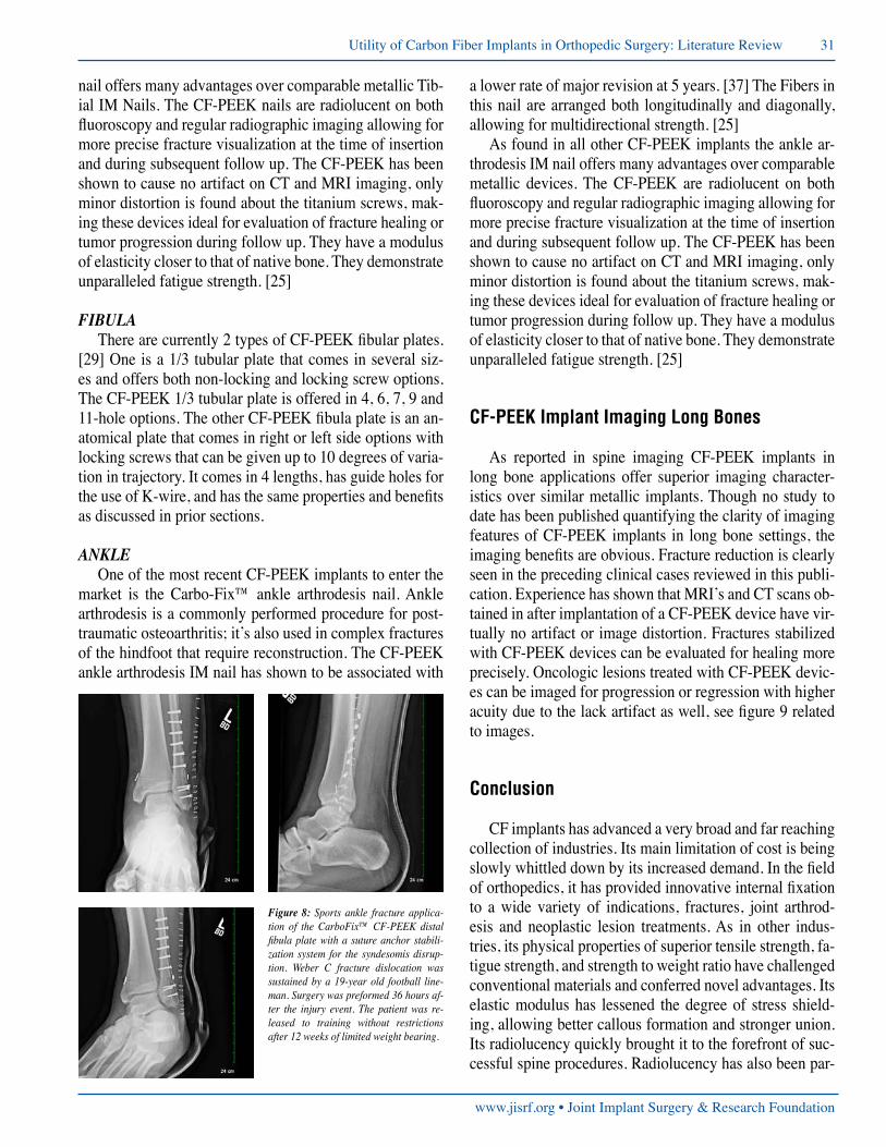
figure 5: Application of a CarboFix™ distal radius plate for stabilization of a patho-logic fracture through the distal radius, benign lesion was curetted, and then allograft bone tissue was packed into the void. Figure (A) is an A/P intra-operative image, (B) is an intra-operative lateral image of the plate and screw construct stabilizing the fracture after curettage, reduction and bone grafting.
A. B.
ic fixation for both cemented and press-fit designs under physiologic load bearing conditions. [31]
As CF has become more established in orthopedics, re-search has responded by analyzing its compatibility with other biomaterials. The combination of Biolox (zirconia toughened alumina) and CF-PEEK with a 40 mm bearing component diameter was tested with a Durham hip wear simulator at 60, 55, and 45 degrees. Although the angle didn’t have a significant effect on the friction, the ceram-ic-on-CF-PEEK combo showed lower wear than either ceramic-on-polymer or metal-on-polymer combinations. [32]
femurA retrospective study of 12 patients with an average
age of 78 years yielded good results even though the plates used were designed for supracondylar periprosthetic fem-oral fractures. 11 of these patients went on to full union with average time of 4 months, while the 12th patient died of pneumonia on post-operative day 18 after a repeat frac-ture of her opposite femur. This study highlighted some of the strengths of CF plates, including elastic modulus half that of bone, decreased stress shielding, and high strain and strength in bending – resulting in higher fatigue strength. [33]
The treatment of periprosthetic femoral fractures with CF plates has also proven successful in elderly patients with significant osteoporosis, restricted mobility, and in the setting of rheumatoid arthritis. A small study of 5 patients treated with supracondylar femoral fractures from low en-ergy trauma over 2 years after a total knee arthroplasty used the lateral approach with carbon fiber plates to repair them. Although 1 patient died of pulmonary embolism 4 weeks post-surgery, all surviving participants showed full clinical and radiological union. [34]
Carbo-Fix™ markets a femoral intramedullary nail made of CF-PEEK. These femoral nails have many of the same features found in traditional metallic IM Nails; ana-tomic bow representing a radian of 1.5 meters, interlocking screw holes that are threaded, cannulated for insertion over a 2.4 mm guide wire, nail cap for the proximal end, im-plantation technique is the same as a typical priformis fosa entry point used in other femoral IM nail. [35]
As with all the Carbo-Fix™ CF-PEEK IM Nails, ra-diopaque markers are embedded about the interlocking screw holes to facilitate positioning during insertion and while drilling under fluoroscopic guidance. The CF-PEEK femoral nails come in lengths of 200 mm to 420 mm with a proximal diameter of 11.5 mm to 12.0 mm and distal di-ameters of 10, 11 and 12 mm. Static Proximal interlock-ing screws perpendicular to the shaft of the nail are placed
30 JISRF Reconstructive Review • Vol. 4, No. 1, March 2014
Joint Implant Surgery & Research Foundation • www.jisrf.org
with an assembly handle-aiming device. Distal interlock-ing screws are placed using the free hand technique in ei-ther static or dynamic options in medial to lateral and/or anterior to posterior orientations. Locking screws are tita-nium. [35]
The CF-PEEK femoral nail offers many advantages over traditional metallic devices of similar design. The CF-PEEK nails are radiolucent on both fluoroscopy and regular radiographic imaging allowing for more precise fracture visualization at the time of insertion and during subsequent follow up. The CF-PEEK has been shown to cause no artifact on CT and MRI imaging, only minor dis-tortion is found about the titanium screws, making these devices ideal for evaluation of fracture healing or tumor progression during follow up. They have a modulus of elasticity closer to that of native bone. They demonstrate unparalleled fatigue strength. [25]
tiBiaCarbo-Fix™ also makes CF-PEEK IM nails for the
treatment of tibia pathology. [36] Like the humeral and Femoral IM Nails they made from continuous CF. The tib-ial IM nail has a 9-degree proximal bend. Screw holes are threaded for more rigid fixation. The proximal interlocks
are placed through an aiming assembly handle, and can be placed in either static or dynamic configurations. Distal in-terlocking screws are placed using free hand fluoroscopic guided technique. A radiopaque marker is oriented along the nails’ axis and about each of the screw holes to facil-itate insertion; screw placement and subsequent imaging during follow up. The tibial nail is inserted over a 2.4 mm smooth tipped guide wire. A nail cap made of CF-PEEK is available if needed (See figure 7).
As found in all other CF-PEEK implants the tibial IM
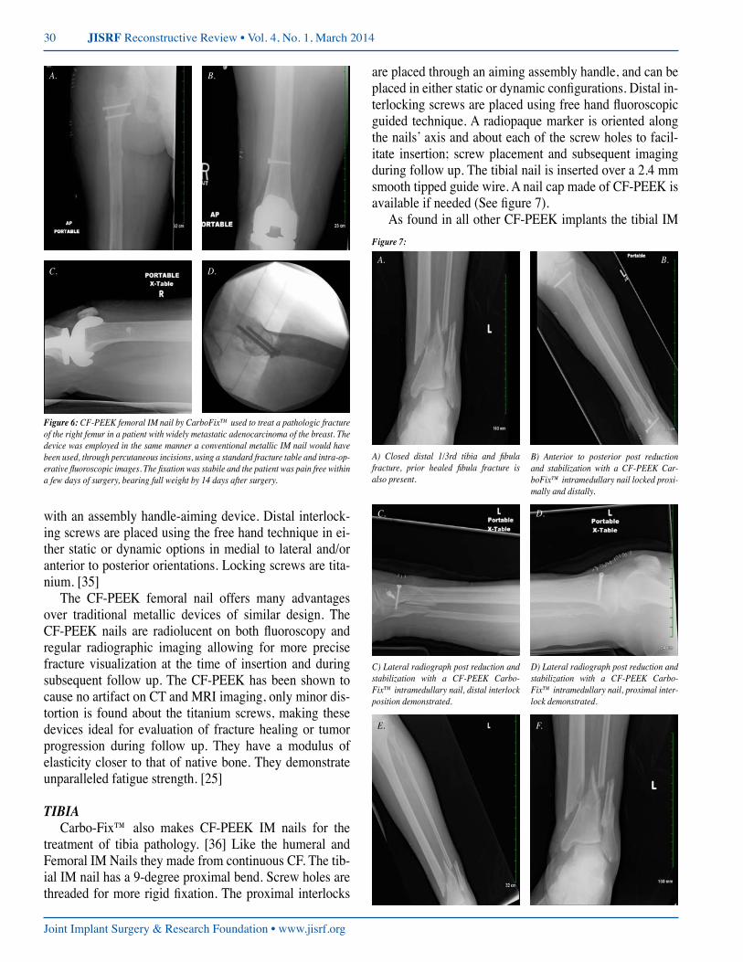
figure 6: CF-PEEK femoral IM nail by CarboFix™ used to treat a pathologic fracture of the right femur in a patient with widely metastatic adenocarcinoma of the breast. The device was employed in the same manner a conventional metallic IM nail would have been used, through percutaneous incisions, using a standard fracture table and intra-op-erative fluoroscopic images. The fixation was stabile and the patient was pain free within a few days of surgery, bearing full weight by 14 days after surgery.
A.
C.
B.
D.
figure 7:
A. B.
C.
E.
D.
F.
A) Closed distal 1/3rd tibia and fibula fracture, prior healed fibula fracture is also present.
B) Anterior to posterior post reduction and stabilization with a CF-PEEK Car-boFix™ intramedullary nail locked proxi-mally and distally.
C) Lateral radiograph post reduction and stabilization with a CF-PEEK Carbo-Fix™ intramedullary nail, distal interlock position demonstrated.
D) Lateral radiograph post reduction and stabilization with a CF-PEEK Carbo-Fix™ intramedullary nail, proximal inter-lock demonstrated.
www.jisrf.org • Joint Implant Surgery & Research Foundation
Utility of Carbon Fiber Implants in Orthopedic Surgery: Literature Review 31
nail offers many advantages over comparable metallic Tib-ial IM Nails. The CF-PEEK nails are radiolucent on both fluoroscopy and regular radiographic imaging allowing for more precise fracture visualization at the time of insertion and during subsequent follow up. The CF-PEEK has been shown to cause no artifact on CT and MRI imaging, only minor distortion is found about the titanium screws, mak-ing these devices ideal for evaluation of fracture healing or tumor progression during follow up. They have a modulus of elasticity closer to that of native bone. They demonstrate unparalleled fatigue strength. [25]
fiBulaThere are currently 2 types of CF-PEEK fibular plates.
[29] One is a 1/3 tubular plate that comes in several siz-es and offers both non-locking and locking screw options. The CF-PEEK 1/3 tubular plate is offered in 4, 6, 7, 9 and 11-hole options. The other CF-PEEK fibula plate is an an-atomical plate that comes in right or left side options with locking screws that can be given up to 10 degrees of varia-tion in trajectory. It comes in 4 lengths, has guide holes for the use of K-wire, and has the same properties and benefits as discussed in prior sections.
ankleOne of the most recent CF-PEEK implants to enter the
market is the Carbo-Fix™ ankle arthrodesis nail. Ankle arthrodesis is a commonly performed procedure for post-traumatic osteoarthritis; it’s also used in complex fractures of the hindfoot that require reconstruction. The CF-PEEK ankle arthrodesis IM nail has shown to be associated with
a lower rate of major revision at 5 years. [37] The Fibers in this nail are arranged both longitudinally and diagonally, allowing for multidirectional strength. [25]
As found in all other CF-PEEK implants the ankle ar-throdesis IM nail offers many advantages over comparable metallic devices. The CF-PEEK are radiolucent on both fluoroscopy and regular radiographic imaging allowing for more precise fracture visualization at the time of insertion and during subsequent follow up. The CF-PEEK has been shown to cause no artifact on CT and MRI imaging, only minor distortion is found about the titanium screws, mak-ing these devices ideal for evaluation of fracture healing or tumor progression during follow up. They have a modulus of elasticity closer to that of native bone. They demonstrate unparalleled fatigue strength. [25]
CF-PEEK Implant Imaging Long Bones
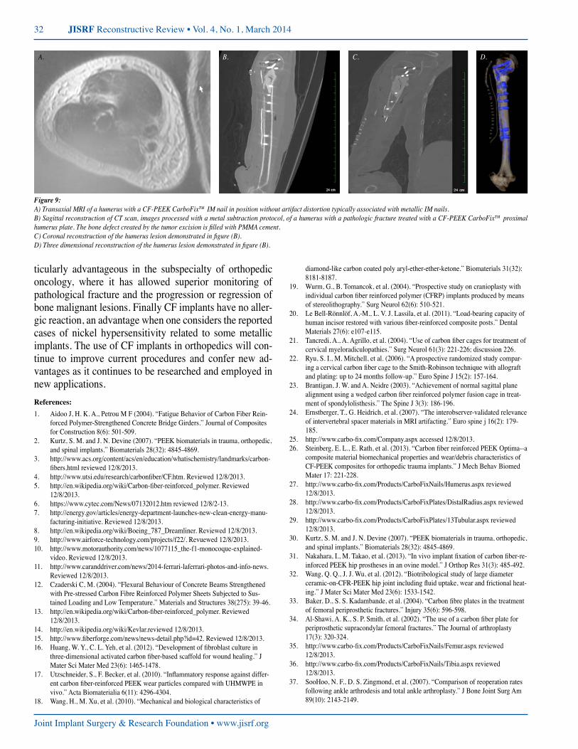
As reported in spine imaging CF-PEEK implants in long bone applications offer superior imaging character-istics over similar metallic implants. Though no study to date has been published quantifying the clarity of imaging features of CF-PEEK implants in long bone settings, the imaging benefits are obvious. Fracture reduction is clearly seen in the preceding clinical cases reviewed in this publi-cation. Experience has shown that MRI’s and CT scans ob-tained in after implantation of a CF-PEEK device have vir-tually no artifact or image distortion. Fractures stabilized with CF-PEEK devices can be evaluated for healing more precisely. Oncologic lesions treated with CF-PEEK devic-es can be imaged for progression or regression with higher acuity due to the lack artifact as well, see figure 9 related to images.
Conclusion
CF implants has advanced a very broad and far reaching collection of industries. Its main limitation of cost is being slowly whittled down by its increased demand. In the field of orthopedics, it has provided innovative internal fixation to a wide variety of indications, fractures, joint arthrod-esis and neoplastic lesion treatments. As in other indus-tries, its physical properties of superior tensile strength, fa-tigue strength, and strength to weight ratio have challenged conventional materials and conferred novel advantages. Its elastic modulus has lessened the degree of stress shield-ing, allowing better callous formation and stronger union. Its radiolucency quickly brought it to the forefront of suc-cessful spine procedures. Radiolucency has also been par-
figure 8: Sports ankle fracture applica-tion of the CarboFix™ CF-PEEK distal fibula plate with a suture anchor stabili-zation system for the syndesomis disrup-tion. Weber C fracture dislocation was sustained by a 19-year old football line-man. Surgery was preformed 36 hours af-ter the injury event. The patient was re-leased to training without restrictions after 12 weeks of limited weight bearing.
32 JISRF Reconstructive Review • Vol. 4, No. 1, March 2014
Joint Implant Surgery & Research Foundation • www.jisrf.org
ticularly advantageous in the subspecialty of orthopedic oncology, where it has allowed superior monitoring of pathological fracture and the progression or regression of bone malignant lesions. Finally CF implants have no aller-gic reaction, an advantage when one considers the reported cases of nickel hypersensitivity related to some metallic implants. The use of CF implants in orthopedics will con-tinue to improve current procedures and confer new ad-vantages as it continues to be researched and employed in new applications.References:1. Aidoo J, H. K. A., Petrou M F (2004). “Fatigue Behavior of Carbon Fiber Rein-
forced Polymer-Strengthened Concrete Bridge Girders.” Journal of Composites for Construction 8(6): 501-509.
2. Kurtz, S. M. and J. N. Devine (2007). “PEEK biomaterials in trauma, orthopedic, and spinal implants.” Biomaterials 28(32): 4845-4869.
3. http://www.acs.org/content/acs/en/education/whatischemistry/landmarks/carbon-fibers.html reviewed 12/8/2013.
4. http://www.utsi.edu/research/carbonfiber/CF.htm. Reviewed 12/8/2013.5. http://en.wikipedia.org/wiki/Carbon-fiber-reinforced_polymer. Reviewed
12/8/2013.6. https://www.cytec.com/News/07132012.htm reviewed 12/8/2-13.7. http://energy.gov/articles/energy-department-launches-new-clean-energy-manu-
facturing-initiative. Reviewed 12/8/2013.8. http://en.wikipedia.org/wiki/Boeing_787_Dreamliner. Reviewed 12/8/2013.9. http://www.airforce-technology.com/projects/f22/. Revuewed 12/8/2013.10. http://www.motorauthority.com/news/1077115_the-f1-monocoque-explained-
video. Reviewed 12/8/2013.11. http://www.caranddriver.com/news/2014-ferrari-laferrari-photos-and-info-news.
Reviewed 12/8/2013.12. Czaderski C, M. (2004). “Flexural Behaviour of Concrete Beams Strengthened
with Pre-stressed Carbon Fibre Reinforced Polymer Sheets Subjected to Sus-tained Loading and Low Temperature.” Materials and Structures 38(275): 39-46.
13. http://en.wikipedia.org/wiki/Carbon-fiber-reinforced_polymer. Reviewed 12/8/2013.
14. http://en.wikipedia.org/wiki/Kevlar.reviewed 12/8/2013.15. http://www.fiberforge.com/news/news-detail.php?id=42. Reviewed 12/8/2013.16. Huang, W. Y., C. L. Yeh, et al. (2012). “Development of fibroblast culture in
three-dimensional activated carbon fiber-based scaffold for wound healing.” J Mater Sci Mater Med 23(6): 1465-1478.
17. Utzschneider, S., F. Becker, et al. (2010). “Inflammatory response against differ-ent carbon fiber-reinforced PEEK wear particles compared with UHMWPE in vivo.” Acta Biomaterialia 6(11): 4296-4304.
18. Wang, H., M. Xu, et al. (2010). “Mechanical and biological characteristics of
diamond-like carbon coated poly aryl-ether-ether-ketone.” Biomaterials 31(32): 8181-8187.
19. Wurm, G., B. Tomancok, et al. (2004). “Prospective study on cranioplasty with individual carbon fiber reinforced polymer (CFRP) implants produced by means of stereolithography.” Surg Neurol 62(6): 510-521.
20. Le Bell-Rönnlöf, A.-M., L. V. J. Lassila, et al. (2011). “Load-bearing capacity of human incisor restored with various fiber-reinforced composite posts.” Dental Materials 27(6): e107-e115.
21. Tancredi, A., A. Agrillo, et al. (2004). “Use of carbon fiber cages for treatment of cervical myeloradiculopathies.” Surg Neurol 61(3): 221-226; discussion 226.
22. Ryu, S. I., M. Mitchell, et al. (2006). “A prospective randomized study compar-ing a cervical carbon fiber cage to the Smith-Robinson technique with allograft and plating: up to 24 months follow-up.” Euro Spine J 15(2): 157-164.
23. Brantigan, J. W. and A. Neidre (2003). “Achievement of normal sagittal plane alignment using a wedged carbon fiber reinforced polymer fusion cage in treat-ment of spondylolisthesis.” The Spine J 3(3): 186-196.
24. Ernstberger, T., G. Heidrich, et al. (2007). “The interobserver-validated relevance of intervertebral spacer materials in MRI artifacting.” Euro spine j 16(2): 179-185.
25. http://www.carbo-fix.com/Company.aspx accessed 12/8/2013.26. Steinberg, E. L., E. Rath, et al. (2013). “Carbon fiber reinforced PEEK Optima--a
composite material biomechanical properties and wear/debris characteristics of CF-PEEK composites for orthopedic trauma implants.” J Mech Behav Biomed Mater 17: 221-228.
27. http://www.carbo-fix.com/Products/CarboFixNails/Humerus.aspx reviewed 12/8/2013.
28. http://www.carbo-fix.com/Products/CarboFixPlates/DistalRadius.aspx reviewed 12/8/2013.
29. http://www.carbo-fix.com/Products/CarboFixPlates/13Tubular.aspx reviewed 12/8/2013.
30. Kurtz, S. M. and J. N. Devine (2007). “PEEK biomaterials in trauma, orthopedic, and spinal implants.” Biomaterials 28(32): 4845-4869.
31. Nakahara, I., M. Takao, et al. (2013). “In vivo implant fixation of carbon fiber-re-inforced PEEK hip prostheses in an ovine model.” J Orthop Res 31(3): 485-492.
32. Wang, Q. Q., J. J. Wu, et al. (2012). “Biotribological study of large diameter ceramic-on-CFR-PEEK hip joint including fluid uptake, wear and frictional heat-ing.” J Mater Sci Mater Med 23(6): 1533-1542.
33. Baker, D., S. S. Kadambande, et al. (2004). “Carbon fibre plates in the treatment of femoral periprosthetic fractures.” Injury 35(6): 596-598.
34. Al-Shawi, A. K., S. P. Smith, et al. (2002). “The use of a carbon fiber plate for periprosthetic supracondylar femoral fractures.” The Journal of arthroplasty 17(3): 320-324.
35. http://www.carbo-fix.com/Products/CarboFixNails/Femur.aspx reviewed 12/8/2013.
36. http://www.carbo-fix.com/Products/CarboFixNails/Tibia.aspx reviewed 12/8/2013.
37. SooHoo, N. F., D. S. Zingmond, et al. (2007). “Comparison of reoperation rates following ankle arthrodesis and total ankle arthroplasty.” J Bone Joint Surg Am 89(10): 2143-2149.
figure 9:A) Transaxial MRI of a humerus with a CF-PEEK CarboFix™ IM nail in position without artifact distortion typically associated with metallic IM nails.B) Sagittal reconstruction of CT scan, images processed with a metal subtraction protocol, of a humerus with a pathologic fracture treated with a CF-PEEK CarboFix™ proximal humerus plate. The bone defect created by the tumor excision is filled with PMMA cement.C) Coronal reconstruction of the humerus lesion demonstrated in figure (B).D) Three dimensional reconstruction of the humerus lesion demonstrated in figure (B).
A. B. C. D.


![[Print] - eMedicine Orthopedic Surgery](https://img.pdfslide.us/doc/110x75/5514008a4a7959df028b4dd8/print-emedicine-orthopedic-surgery.jpg)