Embed Size (px)
Citation preview
Design Criteria UTA BRT
Rev No.
Prepared By
Approved By
Approval Date
Document Date
0 T.W. Jones 2014
Utah Transit Authority Bus Rapid Transit
Design Criteria
Chapter 1 General Requirements and Table of Contents
XXXX 2014

Utah Transit Authority
Table of Contents
CHAPTER 1 GENERAL REQUIREMENTS ................................................................................ 1
1.1 Design Criteria Table of Contents ................................................................................................... 1 1.1.1 Specific Chapters ................................................................................................................ 1
1.2 Purpose ............................................................................................................................................ 1 1.3 Project Goals ................................................................................................................................... 2
1.3.1 Proven Hardware ................................................................................................................ 2 1.3.2 Design Life ......................................................................................................................... 2 1.3.3 Service Integration .............................................................................................................. 2 1.3.4 Design to Cost ..................................................................................................................... 2 1.3.5 Risk Management ............................................................................................................... 3 1.3.6 Baseline BRT System ......................................................................................................... 3
1.4 System Safety and Security ............................................................................................................... 3 1.4.1 Safety Implementation ........................................................................................................ 3 1.4.2 Safety Considerations ......................................................................................................... 4 1.4.3 ADA .................................................................................................................................... 4 1.4.4 Signage................................................................................................................................ 4 1.4.5 Certifiable Items List (CIL) ................................................................................................ 4 1.4.6 Hazard Mitigation ............................................................................................................... 4 1.4.7 Applicable Regulations / Criteria........................................................................................ 5 1.4.8 System Security Goals ........................................................................................................ 5 1.4.9 Security Considerations ...................................................................................................... 5
1.5 System Description........................................................................................................................... 6 1.5.1 Stations................................................................................................................................ 6 1.5.2 Running Way ...................................................................................................................... 6 1.5.3 Speed ................................................................................................................................... 6 1.5.4 Vehicles .............................................................................................................................. 6 1.5.5 Maintenance Facilities ........................................................................................................ 6 1.5.6 Weather Conditions Criteria for Systems Design ............................................................... 6
1.6 Related Documents .......................................................................................................................... 7
UTA Bus Rapid Transit Design Criteria 1-i XXXX 2014 Chapter 1 Revision 0
Utah Transit Authority
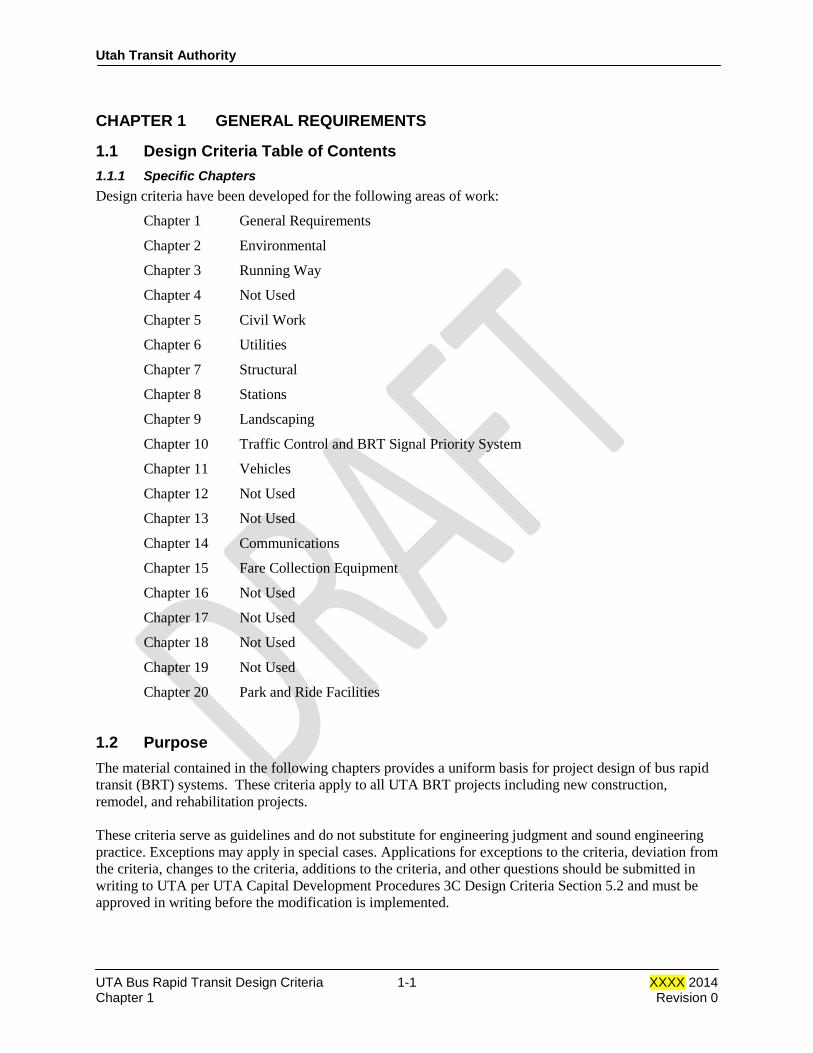
CHAPTER 1 GENERAL REQUIREMENTS
1.1 Design Criteria Table of Contents 1.1.1 Specific Chapters Design criteria have been developed for the following areas of work:
Chapter 1 General Requirements
Chapter 2 Environmental
Chapter 3 Running Way
Chapter 4 Not Used
Chapter 5 Civil Work
Chapter 6 Utilities
Chapter 7 Structural
Chapter 8 Stations
Chapter 9 Landscaping
Chapter 10 Traffic Control and BRT Signal Priority System
Chapter 11 Vehicles
Chapter 12 Not Used
Chapter 13 Not Used
Chapter 14 Communications
Chapter 15 Fare Collection Equipment
Chapter 16 Not Used
Chapter 17 Not Used
Chapter 18 Not Used
Chapter 19 Not Used
Chapter 20 Park and Ride Facilities
1.2 Purpose The material contained in the following chapters provides a uniform basis for project design of bus rapid transit (BRT) systems. These criteria apply to all UTA BRT projects including new construction, remodel, and rehabilitation projects. These criteria serve as guidelines and do not substitute for engineering judgment and sound engineering practice. Exceptions may apply in special cases. Applications for exceptions to the criteria, deviation from the criteria, changes to the criteria, additions to the criteria, and other questions should be submitted in writing to UTA per UTA Capital Development Procedures 3C Design Criteria Section 5.2 and must be approved in writing before the modification is implemented.
UTA Bus Rapid Transit Design Criteria 1-1 XXXX 2014 Chapter 1 Revision 0

Utah Transit Authority
1.3 Project Goals The basic goal of the bus rapid transit system is to provide an improved public transportation system in a cost-effective, environmentally sensitive and socially responsible manner. Design of BRT system elements will be based on a “design to cost” philosophy where the designer works with UTA and the project stakeholders to design the scope of the project such that it can be completed within the project budget. 1.3.1 Proven Hardware The BRT system shall be designed to use proven subsystems hardware and design concepts. All of the major subsystems shall be supplied by established manufacturers, have a documented operating history of previous and current usage, and be available off the shelf, so far as practicable. The same requirements shall apply to spare parts. Waiver of these requirements shall be considered only where the alternative subsystem offers substantial technical and cost advantages, is in an advanced state of development, and has accumulated substantial test data under near-revenue conditions. Specifications for the BRT system shall be prepared in such a way as to encourage competitive bidding by established manufacturers of transportation equipment in accordance with current procurement guidelines. 1.3.2 Design Life The BRT system’s structures such as bridges and culverts shall be designed for a minimum of 75 years. Stations shall be designed for a 30 year life, and other fixed facilities including buildings shall be designed for continued operation over a minimum period of 50 years before complete refurbishment and renovations are necessary due to wear. Major system equipment shall also be designed for a minimum of 30 years before complete replacement becomes necessary, assuming that approved maintenance policies are followed. Where possible, the functional life and capacity of the system shall be designed to match design life of a project element or be sufficiently scalable to accommodate future expansion. 1.3.3 Service Integration The BRT system shall be designed as an integral part of the overall UTA transportation system. Design considerations shall be made for the efficient interchange of passengers to and from private and other public transportation modes. Every project shall accommodate active transportation elements where feasible. 1.3.4 Design to Cost BRT projects shall use the philosophy of budget-limited design. Each major element of the system shall be designed not to exceed the construction budgets established for the project. All systems identified in this document shall meet the criteria established herein and not exceed the project capital costs with appropriate escalation to year and month of construction.
UTA Bus Rapid Transit Design Criteria 1-2 XXXX 2014 Chapter 1 Revision 0
Utah Transit Authority
1.3.5 Risk Management A Risk Management strategy proportional to the size and complexity of each BRT project shall be performed to maintain the project on budget and on schedule. Risks identified and tracked shall include items that may affect the successful implementation of the project. 1.3.6 Baseline BRT System
• At-grade BRT system resulting in safe, yet cost-effective “bare bones, no frills” philosophy. The running way shall be configured to balance the requirements for anticipated ridership, stakeholders needs and desires, and capital, operating, and maintenance costs of the system
• Capital elements to maintain travel speed (traffic signal coordination, transit signal priority, queue jump lanes, and/or exclusive bus lanes)
• BRT station platforms shall have ticket vending machines and the BRT system and all fare collection will occur off-board
• BRT stops spaced ½ to 1 mile apart (may be closer in the central business district)
• Coordinated branding of vehicles and shelters
• Park-and-ride facilities to serve the stations where feasible and appropriate
• Existing utilities protected in place where facility is not in conflict
• BRT corridor minimizing right-of-way and environmental impacts
1.4 System Safety and Security The primary safety goal of the bus rapid transit system is to achieve the highest practicable level of safety while maintaining operational and cost effectiveness. All BRT vehicles, equipment, and facilities shall be designed in accordance with all relevant codes and standards and maintained to ensure safe operation. All employees will take every reasonable precaution to avoid injury to themselves and others during construction and operation of the system. 1.4.1 Safety Implementation Safety to the system’s operators, patrons, and the general public shall be implemented by:
• Appropriate design of BRT vehicles (braking rates, use of fire retardant materials, etc.)
• Appropriate design of the wayside facilities (lighting of platforms, signals, etc.)
• Appropriate design of the corridor in both shared and exclusive running way.
• Appropriate design for pedestrian access to platforms and throughout the corridor.
• Defining and adopting a System Safety and Security Plan The items listed above are incorporated in the technical sections of this Design Criteria Manual. They will also be included in the detailed specifications that will be prepared for the construction and procurement of physical systems.
UTA Bus Rapid Transit Design Criteria 1-3 XXXX 2014 Chapter 1 Revision 0

Utah Transit Authority
1.4.2 Safety Considerations Safety of a transit system is most inherently the design of the system in consideration of its interaction with vehicles and pedestrians during operations. The designer must be cognizant of, plan for and complete designs that are mindful of the safest means of interaction between the travel modes. Safety planning, design and construction should focus on the following guidelines:
• Design systems to be fail safe • Maximize visibility at crossings and along the corridors • Minimize trespassing and hiding opportunities • Provide appropriate lighting, and required emergency backup power • Implement appropriate safety treatments, such as:
o Signage and striping o Pedestrian channelization o Look both ways signage (active and passive) o Sidewalk signage o Tactile tile o Bus warning signs o Curbs to separate/protect running way
The type of treatments to be implemented should be determined after considering BRT speed, visibility, vehicle and pedestrian activity, and school routes. 1.4.3 ADA All design elements will consider and accommodate customers and the public as determined by the Americans with Disabilities Act, to the extent that is feasible. 1.4.4 Signage Standardized systems and signs should be used to provide the public with consistent, meaningful warnings and regulatory information. 1.4.5 Certifiable Items List (CIL) The following elements shall be reviewed and certified before operation of the system:
• Signal System • Structures • Vehicle Design • Pedestrian Crossings • Stations/Platforms • Park and Ride Lots
1.4.6 Hazard Mitigation UTA uses the “21 box” Risk Assessment Matrix which yields hazard ratings of High, Serious, Medium, Low and Eliminated. UTA’s hazard mitigation procedures are outlined in Chapter 6 “Hazard Management Program” of the System Safety Program Plan (SSPP). The simplified process of hazard mitigation is to “Find > Fix > Follow Up” to identify, implement corrective actions and check the effectiveness of the mitigation. The most effective corrective action is to eliminate the hazard. The Preliminary Hazard Analysis (PHA), Operational Hazard Analysis (OHA) and Hold Point processes shall be used when designing, constructing and activation of the BRT system.
UTA Bus Rapid Transit Design Criteria 1-4 XXXX 2014 Chapter 1 Revision 0
Utah Transit Authority
1.4.7 Applicable Regulations / Criteria Current editions of the following criteria, regulations and code should be considered in all designs:
• International Building Code (IBC) • Uniform Plumbing Code • Uniform Mechanical Code • NFPA, Life and Safety Code • NFPA, Life Safety for Transit Systems • Uniform Fire Code • Uniform Federal Accessibility Standards • ANSI A 117.1 • Occupational Safety and Health Standards (OSHA) (29 CFR Part 1910) • Uniform Electrical Code • Americans with Disabilities Act (ADA) • Utah Manual of Uniform Traffic Control Devices (MUTCD) • Crime Prevention Through Environmental Design (CPTED) principles • Transportation Security Agency (TSA) rules and regulations • Department of Homeland Security (DHS) rules and regulations • 49 CFR, 1520 • Local and Utah State law
1.4.8 System Security Goals The primary security goal of the BRT system is to achieve the highest practicable level of security while maintaining operational and cost effectiveness. Secure riders are more likely to use the system, thereby increasing the security of the system by increasing the number of law abiding citizens in the system. Additionally, a secure transit system creates an environment that allows employees to be more focused on maintaining a safe system. While most aspects of BRT security are not pertinent to design, there are key concepts that should be considered during the design process:
• Appropriate design of components to o Increase security for the traveling public o Increase likelihood of criminals being caught o Reduce the potential reward of committing a crime o Take into consideration the Threat and Vulnerability Analysis (TVA)
• Defining and adopting a System Security Plan (SSP) 1.4.9 Security Considerations The designer must be cognizant of, plan for, and complete designs that take into account the current threats and vulnerabilities of the system. It is critical to remember that the transit system is sometimes the target, not just the location, of the crime. The following list is not exhaustive but should offer a starting point:
• Cameras – should be implemented to provide maximum visibility of the infrastructure and to discourage vandalism,
• Emergency phones – should be provided at regular intervals to allow patrons and employees to call for help.
UTA Bus Rapid Transit Design Criteria 1-5 XXXX 2014 Chapter 1 Revision 0
Utah Transit Authority
• Clearly defined borders between public and private (controlled space) – use borders and transition areas while allowing natural or drive-by surveillance will eliminate the attractiveness of the property to criminals.
• Lighting of platforms and parking areas – eliminate shadows where perpetrators can hide. Coordinate light color with camera use to avoid degrading the video quality.
• Avoid alcoves or cul-de-sacs – design structures and appurtenances to eliminate the ability to hide persons, packages, or trash.
• Theft of construction materials – through design, coordinate the construction sequence of the system to allow copper wire and other valuable materials to be secured to avoid theft.
1.5 System Description The design criteria in the following chapters apply to all UTA BRT projects. All system elements will be designed to meet the requirements of the Americans with Disabilities Act (ADA).
1.5.1 Stations The preferred station type is a far-side station (i.e., platform is located on the far-side of an intersection). Platforms shall be 14” high and shall be accessible for disabled patrons. Platform shall be designed for level or near-level boarding. This will be achieved by matching the platform height to the bus. Platforms may be on the side of the road (in shared corridor or outside bus lanes) or in the median of the road (exclusive running way). 1.5.2 Running Way The preferred BRT running way is an exclusive center running way with two lanes. Use of a single/shared lane in the running way will be considered if dictated by economics and if operations of the corridor are acceptable. 1.5.3 Speed The exclusive center running way design speed in exclusive right-of-way shall be the posted highway speed limit where the right-of-way and physical constraints permit. 1.5.4 Vehicles Vehicles may be new or used depending on the cost and timing of the procurement. Vehicles may have doors for both right side and left side loading. 1.5.5 Maintenance Facilities UTA’s existing bus maintenance facilities shall be used for standard maintenance and operations services for the BRT fleet. Additional construction of facilities for BRT shall be evaluated on a case-by-case basis. 1.5.6 Weather Conditions Criteria for Systems Design Systems equipment including vehicles, signal systems, and fare collection equipment shall be capable of maintaining operation within the climatic conditions of the Wasatch Front area. The following data are to be used as the design weather conditions:
UTA Bus Rapid Transit Design Criteria 1-6 XXXX 2014 Chapter 1 Revision 0

Utah Transit Authority
Temperature Range −30° to +110° F Relative humidity 8 to 100% Maximum rainfall in 24 hours 6.7 inches Maximum snowfall in 24 hours 18.4 inches Maximum wind speed 71 mph Freezing rain average of 1 time per year Elevation 4,215-5,000 feet
All facilities shall be designed to accommodate safe storage and/or removal of snow, melting snow, and ice.
1.6 Related Documents Other applicable documents, published separately, for use in design include the current editions of:
• CADD standards
• Project Specific Draft/Final Environmental Impact Statement, Environmental Assessment, Environmental Study Report, or Categorical Exclusion
• Operations and Maintenance Plan
• Fleet Management Plan
• Facilities Master Plan
• System Safety Program Plan
• Project Management Plans
• Storm Water Pollution Protection Plans
• Vehicle Specifications END OF CHAPTER 1.
UTA Bus Rapid Transit Design Criteria 1-7 XXXX 2014 Chapter 1 Revision 0

Design Criteria UTA BRT
Rev No.
Prepared By Approval By
Approval Date
Document Date
0 T.W. Jones 2014
Utah Transit Authority Bus Rapid Transit
Design Criteria
Chapter 2 Environmental
XXXX 2014

Utah Transit Authority
Table of Contents
CHAPTER 2 ENVIRONMENTAL CRITERIA ............................................................................. 1
2.1 General ............................................................................................................................................ 1
2.2 Natural Environment Criteria .......................................................................................................... 1
2.2.1 Geologic Hazard .................................................................................................................. 1 2.2.2 Air Quality .......................................................................................................................... 1 2.2.3 Transit Noise and Vibration ................................................................................................ 1
2.2.3.1 Project Noise .......................................................................................................... 2 2.2.3.2 Construction Noise and Vibration .......................................................................... 2
2.2.4 Water ................................................................................................................................... 2 2.2.4.1 Surface Water Quality ............................................................................................ 2 2.2.4.2 Streams ................................................................................................................... 2 2.2.4.3 Floodplains ............................................................................................................. 3 2.2.4.4 Wetlands ................................................................................................................ 3
2.2.5 Vegetation/Wildlife ............................................................................................................. 3 2.2.6 Hazardous Waste Sites ........................................................................................................ 3 2.2.7 Energy Conservation ........................................................................................................... 4
2.3 Socioeconomic Environment Criteria .............................................................................................. 4
2.3.1 Displacement/Relocations ................................................................................................... 4 2.3.2 Safety/Security .................................................................................................................... 4 2.3.3 Historic, Architectural, Archaeological, and Cultural Resources ........................................ 5
2.3.3.1 Summary of MOA Stipulations .............................................................................. 5 2.3.3.2 Inadvertent Discovery ............................................................................................ 6
2.3.4 Visual .................................................................................................................................. 6 2.3.4.1 Lighting .................................................................................................................. 6 2.3.4.2 Urban Design ......................................................................................................... 6
2.3.5 Public Parks and Greenways ............................................................................................... 6 2.3.6 Environmental Justice ......................................................................................................... 7
2.4 Traffic and Transportation Criteria ................................................................................................. 7
2.5 Construction Criteria ....................................................................................................................... 7
2.5.1 Impacts to Businesses .......................................................................................................... 7 2.5.2 Impacts to Emergency Vehicle Operation ........................................................................... 7
UTA Bus Rapid Transit Design Criteria 2-i XXXX 2014 Chapter 2 Revision 0

Utah Transit Authority
CHAPTER 2 ENVIRONMENTAL CRITERIA
2.1 General This section provides guidance and criteria for implementing environmental features into the Utah Transit Authority’s (UTA) Bus Rapid Transit (BRT) projects. It also establishes criteria by which to avoid, minimize, and/or mitigate environmental impacts. Prior to final design and construction of a BRT project, the project will undergo an environmental review in compliance with the National Environmental Policy Act (NEPA) if a federal nexus exists, or in compliance with UTA’s internal Environmental Review Process for non-federally funded projects without a federal nexus. This review shall include an approved Final Environmental Impact Statement (FEIS) and a Record of Decision (ROD) or a Final Environmental Assessment (EA) and Finding of No Significant Impact (FONSI) issued by the Federal Transit Administration for federally-funded projects, or a Final Environmental Study Report (FESR) and Decision Document (DD) for locally-funded projects. The environmental document for each project will contain mitigation measures, which are intended to reduce the level of adverse effects resulting from implementation of the project. These measures will be formally adopted as part of the project, incorporated into the project design, and reflected in the construction contract documents. During project construction and operation, all activities will be monitored for compliance with the mitigation measures as developed in the environmental document. UTA will prepare a Mitigation Monitoring Plan for each project to ensure all applicable permits are in place and all mitigation commitments are implemented appropriately. The UTA will oversee compliance monitoring for the project.
2.2 Natural Environment Criteria
2.2.1 Geologic Hazard UTA’s service area is seismically active. The maximum magnitude earthquake is 7.25 with a recurrence interval on the order of 1,900 to 2,000 years according to initial geotechnical investigations. The structures are assigned a Seismic Performance Category D in accordance with the American Association of State Highway and Transportation Officials (AASHTO) requirements. This is based on a system of categories A through D with D being the most severe. Unless one has already been prepared by the local jurisdiction, a geotechnical report shall be prepared for the BRT project.
2.2.2 Air Quality Project facilities which provide for the movement of automobiles (i.e., roads and parking lots) shall be designed so as to minimize delays and vehicle idling, thereby minimizing tailpipe emissions. A “hot spot analysis” will be conducted as necessary as part of the environmental documentation to determine if transit-related traffic accessing the stations will affect the level of service at nearby intersections. A dust control plan must be submitted to the Utah Division of Air Quality for any construction activities that will disturb more than ¼ acre.
2.2.3 Transit Noise and Vibration This section presents the noise and vibration design criteria applicable to the operation of vehicles, noise from transit support facilities, and noise attributable to construction of the system, and describes the
UTA Bus Rapid Transit Design Criteria 2-1 XXXX 2014 Chapter 2 Revision 0

Utah Transit Authority
methods to be employed to mitigate noise impacts. The primary goal is to minimize the adverse noise and vibration impacts on the community and, where necessary and appropriate, to provide feasible and reasonable noise and vibration mitigation measures. 2.2.3.1 Project Noise and Vibration When conducting an environmental study for a proposed Capital Development project, UTA will assess the potential for noise and vibration impacts from the proposed project in accordance with FTA’s guidance document Transit Noise and Vibration Impact Assessment (May 2006), and according to the UTA Noise Assessment and Mitigation Procedures. The findings will be documented in a noise and vibration study report and/or the project’s environmental document. The noise and vibration study will identify sensitive receivers that will have moderate or severe noise and/or vibration impacts from the proposed action, and mitigation measures will be developed for those receivers where reasonable and feasible. Mitigation commitments will be specified in the environmental document and may include measures such as construction of sound barriers (such as walls or berms) between the receiver and the noise source, and building noise insulation. Ground-borne vibration from busses is usually caused by uneven roadway surfaces. Smoothing these surfaces usually mitigates the vibration problems. These mitigation commitments will be incorporated into the project design and construction. 2.2.3.2 Construction Noise and Vibration Construction noise is regulated by local ordinances and by U.S. Environmental Protection Agency emission standards for construction equipment. Construction contractors will be contractually required to meet all federal, state, and local noise requirements and ordinances. Noise mitigation measures will be implemented in accordance with the mitigation requirements contained in the environmental document.
2.2.4 Water 2.2.4.1 Surface Water Quality The addition of new fixed facilities may increase the potential for water runoff. This potential extends to both the construction and operation phases of a project. A Utah Pollutant Discharge Elimination System (UPDES) storm water permit shall be obtained by the contractor from the Utah Division of Water Quality prior to the start of construction. As part of this permit, the contractor will develop a Storm Water Pollution Prevention Plan (SWPPP). The SWPPP will include sedimentation and erosion control best management practices (BMPs) for the elimination or reduction of sediment during construction. Methods that may be employed during construction include silt fences, temporary seeding, temporary diversions, sediment traps, and temporary stream crossings. The SWPPP will also include measures for spill prevention, containment, and an emergency cleanup plan. Any required permits from the local storm water management authority shall also be obtained prior to the start of construction. Catch basins, curbing, culverts, gutters, and storm sewers shall be constructed, as necessary, for the permanent control of water runoff during the operation phase of the project. No storm water runoff resulting from the project shall be permitted to enter canals, in compliance with applicable local requirements. 2.2.4.2 Streams Any required stream alteration permits shall be obtained from the Utah State Engineer’s office. The permit applications will be reviewed as required by the U.S. Army Corps of Engineers.
UTA Bus Rapid Transit Design Criteria 2-2 XXXX 2014 Chapter 2 Revision 0

Utah Transit Authority
2.2.4.3 Floodplains Construction of the project has the potential to impact regulatory floodways and floodplains within the corridor. Local county flood control and Federal Emergency Management Agency (FEMA) guidelines shall be observed for the design of the permanent structures and construction activities. Disturbances to creek channels should be held to a minimum. Construction in designated floodplains will require a Section 404 permit from the U.S. Army Corps of Engineers. Construction impacts shall be addressed to mitigate potential water quality and flooding problems. 2.2.4.4 Wetlands Wetlands within or adjacent to project right-of-way will be delineated in the project’s environmental studies. The type and extent of the disturbance shall be coordinated with the U.S. Army Corps of Engineers. Replacement wetlands shall be provided as part of the BRT project if required by the permit requirements and in accordance with applicable laws and regulations. Construction activity shall have a short-term disruption affect and portions of these wetlands could be displaced. The proposed mitigation is to minimize disturbance to these areas, and where direct impacts occur, to restore the wetlands to as near original condition as possible, or as prescribed by the Army Corps of Engineers.
2.2.5 Vegetation/Wildlife As a result of construction, it may be necessary to remove some existing vegetation or disturb existing wild life. In order to mitigate these losses, the following criteria shall apply:
• UTA will comply with all local landscaping ordinances
• Disturbed areas will be revegetated as quickly as possible
• Where existing vegetation is removed, new landscaping shall be planted where possible and appropriate. The placement and types of which vegetation shall be specified in an established landscaping plan.
• The landscaping plan should include a master plant list which identifies new vegetation that is designed to conform to the surrounding environment and be consistent with the operations and maintenance requirements of the BRT system.
• The landscaping plan may extend to the system stations, parking, and public areas of fixed system facilities.
• A program shall be developed for the regular maintenance of system-related landscaping.
• If required, the project design and construction shall be coordinated with the U.S. Fish and Wildlife Service.
2.2.6 Hazardous Waste Sites As defined in federal and state statutes, hazardous substances, hazardous wastes, and special wastes are regulated in all aspects, from their generation, storage, transport, and disposal, including associated reporting and record keeping. In the development and implementation of BRT projects, UTA shall consider hazardous substances, hazardous wastes, and special wastes and shall comply with all applicable regulations and controls.
UTA Bus Rapid Transit Design Criteria 2-3 XXXX 2014 Chapter 2 Revision 0

Utah Transit Authority
Due care shall be exercised to determine whether hazardous substances, hazardous wastes, or special wastes may be present on, adjacent, or in close proximity to property being considered for use in UTA projects. A property may be impacted by such substances or wastes that are located within the property boundaries as well as migration to the property from off-site sources. The presence of hazardous substances, hazardous wastes, or special wastes may impact all aspects of a BRT project, including property acquisition and project construction. For properties being considered for acquisition, a “due diligence” Phase I Environmental Site Assessments (ESA) or Property Transaction Screens (PTS) shall be conducted to determine the presence of such substances or wastes in accordance with the current edition of the American Society for Testing and Material (ASTM) Standard E-1527, “Standard Practice for Environmental Site Assessments: Phase I Environmental Site Assessment Process.” The Phase I ESA or PTS shall be conducted prior to acquisition. Acquisition of an interest in a property determined to contain such substances shall be avoided unless the risks and liabilities of such acquisition can be justified. If avoidance is not feasible, proper management of substances and wastes shall conform to all applicable laws and regulations. For properties where acquisition is not a factor, a Phase I ESA or PTS shall be conducted to identify potential construction-related impacts associated with such substances and wastes. The Phase I ESA shall use the ASTM Phase I ESA standards as a guideline to determine the appropriate level of environmental inquiry necessary to identify and evaluate project specific construction impacts. Once construction impacts have been identified, proper management of substances and wastes encountered during construction shall conform to all applicable laws and regulations.
2.2.7 Energy Conservation In order to reduce energy consumption, conservation features and operating procedures shall be developed for operating systems and subsystems as part of final design activities.
2.3 Socioeconomic Environment Criteria
2.3.1 Displacement/Relocations UTA’s relocation program will provide for studies of the availability of equivalent accommodations, definitions of eligibility for assistance, procedures for dealing with relocations, payment methods, procedures for processing claims and typical schedule event times to effect relocations. This program will provide relocation moving payments to cover actual moving expenses and replacement housing payments or rent supplements where an owner or tenant will have to purchase or rent property at a higher cost or lose a favorable financing arrangement. All relocations shall be carried out in accordance with applicable state laws and requirements. For federally-funded projects, all relocations shall be carried out in accordance with the Federal Uniform Relocation Assistance and Real Property Acquisitions Act of 1970 (Public Law 91-646), as amended.
2.3.2 Safety/Security The implementation of a BRT system carries with it the potential for crimes against persons and property, extending to vehicles, stations, parking areas, and other public areas created by the system. In order to minimize this potential, all system public areas shall be designed to promote maximum safety and security for all system patrons. Specific design measures which shall be employed are discussed in the design criteria for the specific system element.
UTA Bus Rapid Transit Design Criteria 2-4 XXXX 2014 Chapter 2 Revision 0
Utah Transit Authority
2.3.3 Historic, Architectural, Archaeological, and Cultural Resources Section 106 of the National Historic Preservation Act (NHPA) requires that federal agencies, or state agencies that receive federal assistance, consider any effects a project may have on significant cultural resources. In addition, Section 9-8-404 of the Utah Code Annotated (UCA) requires that state agencies “take into account” how their activities will affect historic properties. As part of the environmental study for the BRT project, UTA will identify all historic resources located within the project’s area of potential effect (APE) that are on or eligible for the National Register of Historic Places (NRHP) and will consult with the State Historic Preservation Office (SHPO) to determine the effect of the project on those resources. For projects that will have an Adverse Effect on eligible historic resources, UTA will develop a Memorandum of Agreement (MOA) with the SHPO that identifies the mitigation measures that will be incorporated into the project. For federally-funded projects, FTA will also be a party to the MOA. UCA 63-73-19 protects significant paleontological resources included in or eligible for inclusion in the State Paleontological Register. This regulation requires that state agencies take into account the effect of the project on paleontological resources and allow the director of the Utah Geological Survey (UGS) an opportunity to comment. If the project would have No Effect on paleontological resources, no further action is necessary. If there may be an effect on paleontological resources, documentation and surveys may be required. 2.3.3.1 Summary of MOA Stipulations For sites or properties that are found to be eligible for inclusion in the NRHP, and which will be adversely affected by the BRT project, UTA will consult with the SHPO to develop an appropriate mitigation plan. This mitigation plan will be documented in the MOA. Types of mitigation include but are not necessarily limited to:
• Mitigation for Adverse Effects on historic structures may consist of intensive-level survey documentation. A qualified architectural historian who meets the Secretary of the Interior’s standards for historian or architectural historian must conduct the fieldwork, research, and formal documentation of each building in accordance with the SHPO’s Intensive Level Survey—Basic Survey Standards (Utah State Historic Preservation Office 2007b).
• Mitigation may consist of thorough Historic American Engineering Record documentation. A qualified historian or archaeologist who meets the Secretary of the Interior’s standards for historian or historical archaeologist must conduct the fieldwork, research, and formal documentation of the resource in accordance with the Secretary of the Interior’s Standards and Guidelines for Architectural and Engineering Documentation, consisting of historical research, measured drawings, and large-format black-and-white photography.
• Data Recovery Plans: In consultation with the SHPO, UTA will develop data recovery plans for archaeological sites where it is determined that this treatment will be the most appropriate and effective, considering the design requirements of the BRT project. Plans will be consistent with the Secretary of the Interior’s Standards and Guidelines for Archaeological Documentation.
• Preservation in Place: In consultation with the SHPO, UTA will develop plans for preservation in place for archaeological sites where it has been determined that this treatment will be the most appropriate and effective, considering the design requirements of the BRT project. UTA will implement approved preservation plans to ensure that the archaeological properties selected for such treatment are preserved during construction.
• Educational Component: The project may include an educational component as mitigation for impacts to archaeological sites. The format of the educational component would be developed by UTA in consultation with the SHPO. The educational materials produced could be in the form of a
UTA Bus Rapid Transit Design Criteria 2-5 XXXX 2014 Chapter 2 Revision 0
Utah Transit Authority
popular report suitable for distribution to the public and presenting the results of the archaeological investigations or, as display boards mounted in the trains.
2.3.3.2 Inadvertent Discovery If buried cultural or unanticipated archaeological resources are inadvertently discovered during ground-disturbing activities, the contractor will contact a qualified archaeologist who, in consultation with UTA and the SHPO, will determine the appropriate action to pursue regarding the resource. Work will not resume in the area until approval is given by the UTA Project Manager, in consultation with the SHPO. Buried human remains that were not identified during research or field surveys could be inadvertently unearthed during excavation activities, which could result in damage to the human remains. If human remains of Native American origin are discovered during ground-disturbing activities, it is necessary to comply with state laws relating to the disposition of Native American burials, following state regulation UCA 9-9-401 and the Utah Native American Graves Protection and Repatriation Act of 1992. Utah State Code (63-73-11 through 63-73-19) currently states that paleontological resources are important and requires the preservation of critical fossil resources on State lands. If paleontological resources are unearthed before or during construction, a qualified paleontologist should be notified. The paleontologist then will salvage the fossils and assess the necessity for further mitigation measures, if applicable.
2.3.4 Visual The BRT project may affect visual quality. These impacts may result from removal of existing vegetation and from construction of station or parking lot infrastructure adjacent to residential areas or historic resources. Areas disturbed by construction activities will be re-vegetated as discussed in Section 2.2.5. Design standards for the visual characteristics of stations will be developed in consultation with local jurisdictions through the design review process. 2.3.4.1 Lighting Lighting design shall incorporate CPTED (crime prevention through environmental design) design standards. Area and guideway lighting fixtures and standards shall incorporate directional shielding where needed to avoid the intrusion of unwanted light and glare into adjacent sensitive land uses, such as residential areas. Lighting plans may be subject to local jurisdictional requirements and approval. 2.3.4.2 Urban Design The goal of the BRT system is to provide economical, functional stations that blend with the land uses and community patterns around them. At downtown station sites, historic station sites, mixed-use station sites, and along the corridor, urban design issues shall be addressed in ways that achieve that goal. Urban design plans may be subject to local jurisdictional zoning or design regulations. 2.3.5 Public Parks and Greenways Section 4(f) of the Department of Transportation Act of 1996, as amended (49 USC § 303) protects historic, cultural, public parks, and wildlife refuges from conversion to transportation use unless it can be demonstrated that there is no prudent or feasible alternative. For all projects with a federal nexus, a 4(f) evaluation will be conducted if there is a federal EIS or EA process, documenting the reasons for the use of land, the benefits associated with that use, and lack of prudent or feasible alternatives for avoiding the resource.
UTA Bus Rapid Transit Design Criteria 2-6 XXXX 2014 Chapter 2 Revision 0

Utah Transit Authority
2.3.6 Environmental Justice UTA will consider potential impacts to minority, low-income and disadvantaged populations in the planning and design of its rail and bus service systems. For all projects with a federal nexus and in compliance with NEPA regulations, environmental documents will identify any potential for disproportionate impacts to these populations. UTA will conduct public outreach to inform and consult with environmental justice populations.
2.4 Traffic and Transportation Criteria In areas around BRT stations, increases in local traffic congestion may result. If warranted, local bus service shall be restructured to provide feeder service to BRT stations. Additional or revised traffic signals and transportation system management (TSM) improvements shall be implemented, as determined necessary, in consultation with local jurisdictions.
2.5 Construction Criteria The project construction specifications shall be written to require compliance with all appropriate environmental regulation guidelines and permit requirements. When required, construction impact mitigation plans shall be included in the construction packages. Construction noise and vibration limits shall be defined by the regulations of each jurisdiction.
2.5.1 Impacts to Businesses The following mitigation shall be considered to minimize the impact of construction activities on businesses adjacent to the project:
• Minimize the length of time that any street block is closed.
• Schedule construction during off-peak traffic periods in sensitive areas, if possible.
• Maintain maximum possible number of traffic lanes for operation during construction periods.
• Maintain sidewalks for operation or provide alternative walkways.
• Maintain the visibility of businesses through coordination with local merchants, using temporary signing and other appropriate special measures.
2.5.2 Impacts to Emergency Vehicle Operation Mitigation measures to facilitate the operation of emergency vehicles during the construction phase may include:
• Implementing traffic control measures to reduce congestion (i.e., use of barriers, proper identification of detours, and proper legible signing)
• Informing emergency services providers of construction schedules and activities
• Developing alternative emergency access routes to affected facilities such as hospitals END OF CHAPTER 2.
UTA Bus Rapid Transit Design Criteria 2-7 XXXX 2014 Chapter 2 Revision 0

Design Criteria UTA BRT
Rev No. Prepared By
Approved By
Approval Date
Document Date
0 T.W. Jones 2014
Utah Transit Authority Bus Rapid Transit
Design Criteria
Chapter 3 Bus Running Way
XXXX 2014

Utah Transit Authority
Table of Contents
CHAPTER 3 BUS RUNNING WAY ............................................................................................... 1
3.1 General ............................................................................................................................................ 1
3.2 Types of Running Ways .................................................................................................................... 1
3.2.1 Type I BRT: Mixed Flow Lanes for Buses ......................................................................... 1 3.2.2 Type II BRT: Dedicated Lane for Buses ............................................................................. 1 3.2.3 Type III BRT: Physically Separated Bus Lanes .................................................................. 3 3.2.4 Type IV BRT: Separate Bus Corridor Alignment ............................................................... 4
3.3 Other Design Considerations ........................................................................................................... 5
3.3.1 Pavement Structure ............................................................................................................. 5 3.3.2 Design Vehicle .................................................................................................................... 5 3.3.3 Access by Non-Bus Traffic ................................................................................................. 6
3.3.3.1 Pedestrian Access ................................................................................................... 6 3.3.3.2 Vehicular Traffic Access ........................................................................................ 6
3.3.4 Drainage .............................................................................................................................. 6 3.3.5 Signing and Striping ............................................................................................................ 6
UTA Bus Rapid Transit Design Criteria 3-i XXXX 2014 Chapter 3 Revision 0

Utah Transit Authority
CHAPTER 3 BUS RUNNING WAY
3.1 General A running way is the portion of the roadway that buses utilize for their operations. Running ways can be shared with general traffic or separated from general traffic. This section establishes the basic criteria to be used for BRT running way design. Most BRT projects will utilize UDOT, city, or county owned roadways. Roadway and bus running way design in such public rights-of-way shall be in conformance with the standards and criteria of the governing agency owning the roadway.
3.2 Types of Running Ways Running way types vary in the degree of lateral and grade separation from general traffic. UTA has defined four types of BRT running ways based upon these degrees of separation. These running way types are:
• Type I BRT: Mixed flow lanes for buses • Type II BRT: Dedicated lane for buses • Type III BRT: Physically separated bus lane • Type IV BRT: Separated bus corridor alignment
3.2.1 Type I BRT: Mixed Flow Lanes for Buses
Mixed flow lanes are the most basic form of a BRT running way. A Type I BRT system shares lanes with general automobile traffic in a similar manner as a local bus route. Figure 3.1 depicts a typical section of a Type I configuration.
Intersection specific running way improvements may also include bus bypass lanes and queue jumps.
Figure 3.1
3.2.2 Type II BRT: Dedicated Lane for Buses
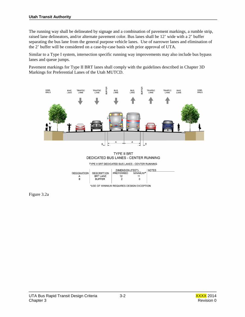
As shown in Figures 3.2a and 3.2b,, a Type II BRT running way has a dedicated lane for bus traffic. Other vehicles are restricted from using the BRT lanes. The exclusive lane can be either at the center of the roadway, or along the outside of the roadway (side running). No physical barrier (i.e. a curb) is used in a Type II BRT system. An additional 2 foot horizontal separation between the general traffic lanes and the BRT lanes is required.
UTA Bus Rapid Transit Design Criteria 3-1 XXXX 2014 Chapter 3 Revision 0
Utah Transit Authority
The running way shall be delineated by signage and a combination of pavement markings, a rumble strip, raised lane delineators, and/or alternate pavement color. Bus lanes shall be 12’ wide with a 2’ buffer separating the bus lane from the general purpose vehicle lanes. Use of narrower lanes and elimination of the 2’ buffer will be considered on a case-by-case basis with prior approval of UTA.
Similar to a Type I system, intersection specific running way improvements may also include bus bypass lanes and queue jumps.
Pavement markings for Type II BRT lanes shall comply with the guidelines described in Chapter 3D Markings for Preferential Lanes of the Utah MUTCD.
Figure 3.2a
UTA Bus Rapid Transit Design Criteria 3-2 XXXX 2014 Chapter 3 Revision 0

Utah Transit Authority
Figure 3.2b
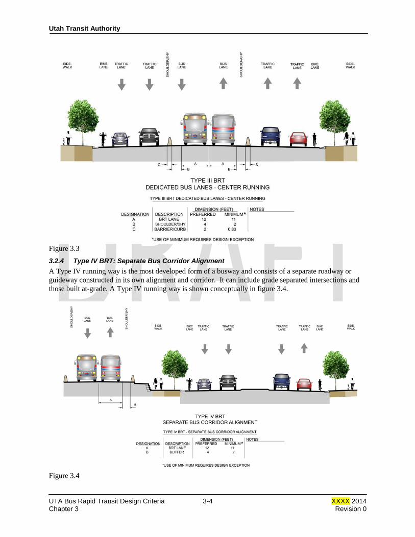
3.2.3 Type III BRT: Physically Separated Bus Lanes A Type III BRT running way is similar to the Type II except the bus lanes are physically separated by a curb or other barrier. A non-mountable barrier curb, similar to a UDOT type B3 curb, is the preferred method of separation from the automobile traffic lanes. Bus lanes shall be 12’ wide with a 4’ shy distance to the face of curb (preferred) and 2’ shy distance (minimum). Use of narrower lanes or elimination of the shy distance will be considered on a case-by-case basis with prior approval of UTA. The design speed of the running way shall match the design speed of the roadway. Figure 3.3 illustrates a Type III running way.
Pavement markings for Type III BRT lanes shall comply with the guidelines described in Chapter 3D Markings for Preferential Lanes of the Utah MUTCD.
UTA Bus Rapid Transit Design Criteria 3-3 XXXX 2014 Chapter 3 Revision 0
Utah Transit Authority
Figure 3.3
3.2.4 Type IV BRT: Separate Bus Corridor Alignment A Type IV running way is the most developed form of a busway and consists of a separate roadway or guideway constructed in its own alignment and corridor. It can include grade separated intersections and those built at-grade. A Type IV running way is shown conceptually in figure 3.4.
Figure 3.4
UTA Bus Rapid Transit Design Criteria 3-4 XXXX 2014 Chapter 3 Revision 0
Utah Transit Authority
The geometry of the running way will influence the comfort of passengers, especially those who are standing. Abrupt changes in horizontal alignment shall be avoided as much as practicable. The geometry of the running way shall meet current AASHTO guidelines. The design speed should be chosen to match those of major comparable thoroughfares. Bus lanes shall be 12’ wide with 4’ shoulders/shy distance (preferred, 2’ shoulders/shy distance minimum). Use of narrower lanes and shoulders will be considered on a case-by-case basis with prior approval of UTA.
3.3 Other Design Considerations
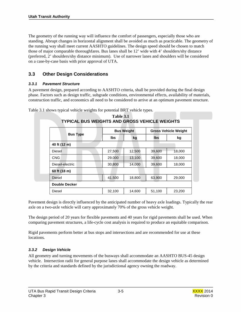
3.3.1 Pavement Structure A pavement design, prepared according to AASHTO criteria, shall be provided during the final design phase. Factors such as design traffic, subgrade conditions, environmental effects, availability of materials, construction traffic, and economics all need to be considered to arrive at an optimum pavement structure. Table 3.1 shows typical vehicle weights for potential BRT vehicle types.
Table 3.1 TYPICAL BUS WEIGHTS AND GROSS VEHICLE WEIGHTS
Bus Type Bus Weight Gross Vehicle Weight
lbs kg lbs kg
40 ft (12 m)
Diesel 27,500 12,500 39,600 18,000
CNG 29,000 13,100 39,600 18,000
Diesel-electric 30,800 14,000 39,600 18,000
60 ft (18 m)
Diesel 41,500 18,800 63,900 29,000
Double Decker
Diesel 32,100 14,600 51,100 23,200
Pavement design is directly influenced by the anticipated number of heavy axle loadings. Typically the rear axle on a two-axle vehicle will carry approximately 70% of the gross vehicle weight. The design period of 20 years for flexible pavements and 40 years for rigid pavements shall be used. When comparing pavement structures, a life-cycle cost analysis is required to produce an equitable comparison. Rigid pavements perform better at bus stops and intersections and are recommended for use at these locations.
3.3.2 Design Vehicle All geometry and turning movements of the busways shall accommodate an AASHTO BUS-45 design vehicle. Intersection radii for general purpose lanes shall accommodate the design vehicle as determined by the criteria and standards defined by the jurisdictional agency owning the roadway.
UTA Bus Rapid Transit Design Criteria 3-5 XXXX 2014 Chapter 3 Revision 0

Utah Transit Authority
3.3.3 Access by Non-Bus Traffic 3.3.3.1 Pedestrian Access Separate busways, while posing advantages due to restricted access and ability to travel at higher speeds, have the added responsibility of limiting access to pedestrians as well as vehicular traffic. Where the busway is located in its own corridor (Type IV), a fence or other barrier should be provided throughout the length of the busway for safety, for pedestrian control and to prevent trash dumping. Engineering judgment may dictate exceptions in areas of precipitous slopes or other natural barriers to access or in park like areas. “No Trespassing” signs should be mounted on the fence or barrier at appropriate intervals. Where pedestrian crossings are required, it is recommended that they be at signalized crossing locations to avoid conflicts with buses. 3.3.3.2 Vehicular Traffic Access While access by vehicles other than buses is discouraged in the running way, provision may be made for emergency vehicle access through special access points. The location of these special access points shall be coordinated with the local municipality providing emergency services. In the case of a Type III running way, access points on each side of the running way shall be staggered so as to discourage vehicles turning across the bus right-of-way.
3.3.4 Drainage
Adequate drainage of the running way is necessary to provide a safe driving surface and for preserving pavement life. In a Type I or II running way, water is allowed to sheet flow across the lanes of traffic. In a side running situation (Type II), the gutter spread from the design event should not compromise the bus lane. In a Type III or IV running way, the storm water will be contained within the busway. Consequently storm drain inlets may be required in the right-of-way. Design the drainage such that the spread from a 10 year storm shall be limited to the shoulder within the running way or 3 feet, whichever is greater.
For additional criteria pertaining to drainage see Chapter 5 of this design criteria manual.
3.3.5 Signing and Striping
Refer to Chapter 10 of the UTA BRT Design Criteria for guidelines defining signing and striping. END OF CHAPTER 3.
UTA Bus Rapid Transit Design Criteria 3-6 XXXX 2014 Chapter 3 Revision 0

Design Criteria UTA Bus Rapid Transit
Rev No.
Prepared By
Approved By
Approval Date
Document Date
0 T.W. Jones 2014
Utah Transit Authority Bus Rapid Transit
Design Criteria
Chapter 5 Civil Work
XXXX 2014
Utah Transit Authority
Table of Contents
CHAPTER 5 CIVIL WORK .............................................................................................................. 1
5.1 General ............................................................................................................................................ 1
5.2 Surveying and Mapping ................................................................................................................... 1
5.2.1 Survey Control System ........................................................................................................ 1 5.2.1.1 Horizontal Control ................................................................................................. 1 5.2.1.2 Vertical Control ...................................................................................................... 1
5.2.2 Surveys and Monumentation ............................................................................................... 1
5.3 Grading ............................................................................................................................................ 2
5.4 Roadway Elements ........................................................................................................................... 2
5.4.1 General ................................................................................................................................ 2 5.4.2 Applicable Standards .......................................................................................................... 2
5.4.2.1 American Association of State Highway and Transportation Officials (AASHTO)2 5.4.2.2 Utah Department of Transportation (UDOT) ......................................................... 3 5.4.2.3 County and Local Jurisdictions .............................................................................. 3 5.4.2.4 American Public Works Association (APWA) ...................................................... 3
5.4.3 Roadway Geometry ............................................................................................................. 3 5.4.3.1 Traffic Lane Widths ............................................................................................... 3 5.4.3.2 Number of Traffic Lanes ........................................................................................ 3 5.4.3.3 On-street Parking ................................................................................................... 3 5.4.3.4 Superelevation and Cross Slopes ........................................................................... 3
5.4.4 Ramps and Curb Cuts ......................................................................................................... 3 5.4.5 Sidewalks and Park Strips ................................................................................................... 4 5.4.6 Stairs ................................................................................................................................... 4 5.4.7 Driveways ........................................................................................................................... 4 5.4.8 Local Bus Service ............................................................................................................... 4
5.5 Paving .............................................................................................................................................. 4
5.6 Pavement Marking ........................................................................................................................... 5
5.7 Traffic Maintenance ......................................................................................................................... 5
5.8 Drainage .......................................................................................................................................... 5
5.8.1 General ................................................................................................................................ 5 5.8.2 Submittals ........................................................................................................................... 5 5.8.3 BRT Drainage ..................................................................................................................... 6 5.8.4 Hydrology and Hydraulics................................................................................................... 6
5.8.4.1 Design Method ....................................................................................................... 6 5.8.4.2 Storm Frequency .................................................................................................... 6
UTA Bus Rapid Transit Design Criteria 5-i XXXX 2014 Chapter 5
Utah Transit Authority
5.8.5 Selection of Drainage Structures ......................................................................................... 7 5.8.6 Pipe Size and Materials ....................................................................................................... 7 5.8.7 Location of Drains ............................................................................................................... 7 5.8.8 Parking Lots ........................................................................................................................ 7 5.8.9 Storm Water Management and Sediment Control ............................................................... 7 5.8.10 Detention Requirements ...................................................................................................... 8
5.9 Right-of-Way .................................................................................................................................... 8
5.9.1 General ................................................................................................................................ 8 5.9.2 Types of Property Ownership and Rights ............................................................................ 8
5.9.2.1 Fee Simple Title ..................................................................................................... 8 5.9.2.2 Easements .............................................................................................................. 9
5.9.3 Right-of-Way Limits ........................................................................................................... 9 5.9.3.1 At-Grade Construction ........................................................................................... 9 5.9.3.2 Storm Drainage and Utilities ................................................................................ 10 5.9.3.3 Stations and Park-and-Ride Lots .......................................................................... 10
5.9.4 Right-of-Way Information Requirements .......................................................................... 10
UTA Bus Rapid Transit Design Criteria 5-ii XXXX 2014 Chapter 5
Utah Transit Authority
CHAPTER 5 CIVIL WORK
5.1 General This section establishes the basic civil engineering criteria to be used in design of Bus Rapid Transit facilities. Civil design in public rights-of-way shall be in conformance with the specification and design guidelines of UDOT Standard Drawings or as determined otherwise for the local agency having jurisdiction. Drainage shall meet the requirements and design guidelines of the local agency having jurisdiction for the subject drainage.
5.2 Surveying and Mapping
5.2.1 Survey Control System 5.2.1.1 Horizontal Control All horizontal controls shall be based on the Utah State Plane Coordinate System, NAD’83 in the appropriate zone and shall be reported in US Survey Feet. The precision of any secondary horizontal ground control surveys shall be, as a minimum, 1:50,000. All subsequent horizontal surveys shall, as a minimum, have a precision of 1:25,000.
5.2.1.2 Vertical Control Vertical controls for this project shall be based on the North American Vertical Datum of 1988 (NAVD88) as defined by the National Geodetic Survey (NGS). The precision of the vertical ground control and of supporting vertical ground surveys shall be at least Second Order, Class I, as defined by the Federal Geodetic Control Committee and published under the title “Classifications, Standards of Accuracy and General Specification of Geodetic Control Stations,” authored by the National Geodetic Survey in February 1974.
5.2.2 Surveys and Monumentation Using field surveys, record information and computations, the surveyor shall provide individual plats of survey. The final plats shall comply with the recording requirements of the state of Utah, and appropriate counties and municipalities. The ROW envelope shall be described by metes and bounds, ensuring that the pertinent portions of all tracts, subdivisions, U.S. lands, parcels, and other areas affected by the envelope shall be similarly described and shown on the plats. Coordinates shall be provided for corners and angle and curve points along the limits of the ROW. If possible, all existing monuments are to be shown on the plans, and restored to their original locations if disturbed during construction.
UTA Bus Rapid Transit Design Criteria 5-1 XXXX 2014 Chapter 5

Utah Transit Authority
Permanent monuments shall be used wherever monumentation is required. Monuments shall be placed at each point of curve (PC) and point of tangent (PT) of right-of-way line curves, and as necessary to satisfy involved jurisdictions.
5.3 Grading The design drawings shall clearly depict the limits of permissible construction disturbance, which shall include only those areas necessary for construction of the proposed facilities. Requirements for clearing, grubbing, and removing unsuitable materials shall be defined. Areas disturbed by construction shall be protected by an erosion and sediment control system approved by the appropriate local agency having jurisdiction. Methods of erosion control to be considered include seeding and mulching, sodding, application of geotextile fabrics to stabilize areas, and application of gravel or coarse rock. In areas where fill slopes may encroach upon properties adjacent to UTA right-of-way, the use of retaining structures should be considered. The flattest practical and economically beneficial cut and fill slopes shall be utilized up to a maximum of two horizontal to one vertical (2:1). Any slope steeper than 2:1 requires a geotechnical analysis. Cut/fill slopes must be conducive to the establishment of permanent vegetation for erosion control/slope stabilization. Use of a 2:1 slope for any cut/fill greater than 6’ high shall require prior approval of UTA. Cut/fill slope design shall be confirmed during the geotechnical investigation.
5.4 Roadway Elements
5.4.1 General For general project consistency, the design standards for arterial, collector, and local roads shall be in conformance with AASHTO Standards and the standards of the jurisdictional agency of that road, except as modified herein. Design the pavement structural section to optimize the life-cycle cost of the roadway over a 20 year period. The criteria set forth in this section are applicable to the design of alterations of existing streets, new streets, and UTA facilities. They also apply to modifications made to driveways and parking lots of adjacent property required to construct UTA facilities, in the absence of any other stipulations by the property owner.
5.4.2 Applicable Standards The most current editions of these documents are incorporated into these design criteria by reference and shall be adhered to wherever possible in the design of roads, parking and related traffic control except when specified in this manual. If criteria sources conflict, the standards adopted by the jurisdictional agency shall be used unless otherwise directed by UTA. 5.4.2.1 American Association of State Highway and Transportation Officials (AASHTO)
• A Policy on Geometric Design of Highways and Streets
• Roadside Design Guide
• AASHTO (LRFD) Bridge Design Specifications
• Guide for the Development of Bicycle Facilities
• Guide for the Planning, Design, and Operation of Pedestrian Facilities
UTA Bus Rapid Transit Design Criteria 5-2 XXXX 2014 Chapter 5
Utah Transit Authority
5.4.2.2 Utah Department of Transportation (UDOT)
• UDOT Standard and Supplemental Specifications for Road and Bridge Construction
• UDOT Standard and Supplemental Drawings for Road and Bridge Construction
• UDOT Manuals of Instruction 5.4.2.3 County and Local Jurisdictions
• Applicable Ordinances and Standard Drawings 5.4.2.4 American Public Works Association (APWA)
• Applicable standards
5.4.3 Roadway Geometry New facilities shall be designed in accordance with the criteria listed in this manual. 5.4.3.1 Traffic Lane Widths Traffic lane widths shall conform to local jurisdictional standards. Bus lanes shall be 12’ wide. Use of narrower bus lanes will be considered on a case-by-case basis with prior approval of UTA. 5.4.3.2 Number of Traffic Lanes Unless required to mitigate traffic impacts of the BRT system as defined in the environmental study report or environmental impact statement, existing roadways shall be replaced with the same lane configurations. Access roads to the station facilities, as required, shall be built to accommodate traffic volumes anticipated in the design year as determined by an appropriate traffic analysis which considers projected traffic volumes, critical traffic movements, and geometric configurations.. 5.4.3.3 On-street Parking Parking locations shall be determined in consultation with the jurisdictions based on traffic analysis, safety considerations, and demand for on-street parking. Twenty-four hour parking prohibition shall be recommended at locations (i.e., near intersections and at BRT stations) where roadway width is not adequate to provide the combination of the necessary number of through lanes and on-street parking. Peak hour parking may be considered at locations where traffic analysis shows that the capacity of the traveled way provides level of service C or better. 5.4.3.4 Superelevation and Cross Slopes Superelevations and cross slopes shall be in accordance with local jurisdictional standards. Cross slope shall be considered when designing bus-specific paved areas.
5.4.4 Ramps and Curb Cuts Pedestrian access ramps and curb cuts shall be provided in the following locations and circumstances:
• Existing ramps affected by construction shall be replaced or relocated.
• At intersections where a sidewalk exists and the curb returns are to be modified. It is not necessary to provide ramps and curb cuts where no sidewalk exists.
• At intersections and mid-block crosswalks where new curb and sidewalk are to be constructed.
UTA Bus Rapid Transit Design Criteria 5-3 XXXX 2014 Chapter 5

Utah Transit Authority
• In the vicinity of all designated accessible parking spaces.
• In all locations where pedestrian paths to the stations cross curbs on UTA property. This includes routes from parking lots, bus loading locations, and public streets.
Detectable warnings shall be installed at all pedestrian access ramps. The design and location of curb cuts and ramps shall be in accordance with the applicable provisions of UDOT Standard Drawings, the USDOT Standards for Accessible Transportation Facilities to comply with the Americans with Disabilities Act (ADA), and the local governing jurisdiction. The provisions of this section do not apply to station platforms, which are described Chapter 8 of the UTA BRT Design Criteria.
5.4.5 Sidewalks and Park Strips Sidewalks, park strips, and planting areas, if required, shall comply with the standards of UDOT or the local agency having jurisdiction. Existing sidewalks impacted by the project shall be repaired or replaced in kind where practical. On UTA property, sidewalks shall be located immediately adjacent to the curb where curbs are provided. Where no curbs are to be provided, the sidewalk shall be separated from roadway pavements by a minimum of 4 feet. Walkways which do not parallel streets shall be constructed to the same standards as sidewalks. No stairways shall be used in walkways unless an alternate route that meets the requirements of ADA is located in close proximity.
5.4.6 Stairs The minimum width of stairs for public use shall be 48 inches. The minimum length of landing for straight-line stairs shall be 54 inches.
5.4.7 Driveways Driveway characteristics, including pavement type and minimum width, shall meet state, county, or local standards as applicable. In general, all existing driveways impacted by the project shall be replaced in kind. Driveway closings required to facilitate UTA operations or construction shall be approved by the local agency having jurisdiction.
5.4.8 Local Bus Service Local bus service issues, including, but not limited to, local bus stop and shelter placements, bus loading zones, and local bus service connections to the BRT system, shall be coordinated with the local UTA business unit.
5.5 Paving New pavements shall be of materials conforming to the latest standards of the agency having jurisdiction and maintenance responsibility. Restored or widened pavements shall be of materials similar to those existing prior to construction. However, where existing materials and components are found to include obsolete paving materials such as wood block, replacement shall not be in kind but shall meet current specifications and practices. Road reconstructions should match existing surface type. The pavement section of roadway widening shall match the adjacent pavement section.
UTA Bus Rapid Transit Design Criteria 5-4 XXXX 2014 Chapter 5

Utah Transit Authority
Roads and parking surfaces shall be either Portland cement concrete or bituminous concrete, except bus pads and bus acceleration and deceleration zones shall be Portland cement concrete. All pavements shall be designed for the expected traffic volumes. Pavement mix characteristics shall be selected based on standard practice and as commonly available in the local jurisdiction.
5.6 Pavement Marking Pavement marking on public streets shall be in accordance with the requirements of the relevant jurisdiction. Pavement marking on roadways within UTA property shall be in accordance with the latest edition of Utah MUTCD. Parking stalls shall be delineated with 4-inch white stripes.
5.7 Traffic Maintenance The maintenance and protection of both vehicular and pedestrian traffic during construction shall be properly addressed during design, and delineated on plan documents. The design shall be in accordance with Utah MUTCD, and the additional requirements of the applicable jurisdiction where applicable, and shall include traffic staging and detour plans. Plans shall be as approved by local authorities.
5.8 Drainage
5.8.1 General The design of drainage systems using the criteria contained herein is to protect the BRT system and adjacent facilities from storm runoff damage, and to provide for environmentally responsible handling of storm drainage during construction. The design of new drainage facilities shall be in accordance with the criteria of the local county and, as applicable, the local agency having jurisdiction. Required relocation of existing drainage facilities shall be “replacement-in-kind” or “equal construction,” where the BRT construction does not change the design flows. Local agencies having jurisdiction over drainage shall be consulted regarding potential betterments of existing facilities to be replaced.
5.8.2 Submittals Design of drainage facilities requiring review and approval of jurisdictional agencies shall be submitted in accordance with the procedures established by the respective agency. Agencies having jurisdiction may include US Army Corps of Engineers, UDOT, Utah Department of Natural Resources, county flood control and/or soil conservation districts, and local municipalities. All maintenance during construction, relocation, and restoration of drainage facilities shall conform to the most current edition of the respective design criteria, as listed below, for the agencies that may be affected by BRT drainage construction.
• Utah Department of Transportation: UDOT Standard Drawings and Specifications and the UDOT Manuals of Instruction
• Local county criteria
• Applicable local jurisdiction
UTA Bus Rapid Transit Design Criteria 5-5 XXXX 2014 Chapter 5
Utah Transit Authority
5.8.3 BRT Drainage BRT drainage criteria only apply to the design of drainage facilities in the BRT right-of-way/running way. Drainage of other facilities and connections to other drainage systems shall be designed in accordance with the criteria of the agency having jurisdiction. As far as practical, drainage shall be by gravity flow. Where sections are below points where gravity outfalls cannot be provided, pumping stations may be necessary, subject to the approval of UTA. No sanitary sewer discharge shall be permitted to enter any drainage system.
5.8.4 Hydrology and Hydraulics The following procedures shall be used in preparing hydrologic computations for BRT drainage. 5.8.4.1 Design Method
a. Methodologies—Hydrologic and hydraulic design shall be in accordance with the procedures and criteria as described in the current version of the UDOT Standard and Supplemental Drawings, UDOT Manual of Instruction for Roadway Drainage, the Utah Department of Natural Resources regulations, U.S. Soil Conservation Service Technical Release No. 55 (TR-55), “Urban Hydrology for Small Watersheds”, as established by local municipalities, or other methodology used by pertinent agencies having jurisdiction.
b. All storm water facilities draining 5 acres or less shall be designed for the maximum expected discharge, determined by the Rational Method. Storm water facilities draining areas may require water storage or detention considerations. Therefore, a hydrograph method shall be used for the applicable storm frequencies. The U.S. Soil Conservation Service TR-55 or TR-20 are acceptable. In jurisdictions with more strict guidelines, local codes and guidelines shall take precedence.
c. All cross culverts and storm water management facilities draining 5 acres or less may be designed for the expected discharge from the applicable design storm, determined by using the “United States Soil Conservation Service (SCS) Hydrograph Method” utilizing either (1) the TR-20 computer program or (2) the TR-55 Tabular Hydrograph Method using SCS Type 2 storm distribution.
d. If no water storage or potential detention considerations exist, storm water facilities draining more than 640 acres (1 square mile) may be designed for the maximum expected discharge determined by using the Recommended Hydrologic Methods as defined by the UDOT Drainage Manual of Instructions.
e. The hydraulic capacity of open channels, swales, gutters, storm sewer pipe systems, and culverts shall be determined using the Manning equation. The hydraulic parameters of a stream shall be determined using the HEC-RAS computer program. The definition of a stream shall be determined by the local jurisdiction having authority. Open channels and swales shall be protected where the flow velocities exceed the values allowed by the UDOT Manual of Instruction for Roadway Drainage.
5.8.4.2 Storm Frequency The following facilities shall be designed/protected by accommodating the storm frequency listed:
• All culverts and drainage facilities crossing 50-year design the BRT system where flooding could damage
UTA Bus Rapid Transit Design Criteria 5-6 XXXX 2014 Chapter 5
Utah Transit Authority
the system
• Parking lots, roadways, running way 10-year
• All longitudinal drains that could flood 50-year roadbed
Storm facility design shall be in accordance with local jurisdictional requirements.
5.8.5 Selection of Drainage Structures Wherever possible, drainage structures to be maintained by UTA shall meet UDOT and/or UTA standards. In cases in which the standard drainage structures are not suitable, structures shall be designed to satisfy the conditions. Drainage structures on a state, county, or local facility shall comply with the standards of the applicable agency.
5.8.6 Pipe Size and Materials
• Storm drains shall be minimum of 18″ diameter.
• Underdrains shall be minimum of 8″ diameter.
• Crossing culverts shall be a minimum of 24″ diameter.
• Pipe materials shall be chosen based on a life cycle analysis and soil type, and shall conform to local jurisdictional requirements.
5.8.7 Location of Drains In the track sections, manholes or cleanout boxes shall be provided at maximum 400 foot spacing for the selected type. Manholes or cleanout boxes within the roadway section shall be spaced according to the local jurisdictional requirements. Inlets shall be provided at required drainage catch points. Place flanking inlets on either side of the inlet at the sag point in a sag vertical curve. Underdrain cleanouts shall be provided at maximum 200 foot centers along all drainage lines. Cleanouts are required at each 90-degree bend and for every two 45-degree bends..
5.8.8 Parking Lots Parking lots shall be designed so that storm water is removed by overland flow to a gutter or curb and gutter then to an inlet where the water shall enter either a closed drainage system or an open ditch. The maximum velocity of flow out of the parking lot shall be as directed by local criteria. Overland flow should be on at least a 1% grade. The maximum permissible spread for gutter flow shall be 12 feet.
5.8.9 Storm Water Management and Sediment Control Sediment control shall be in accordance with the standards and specifications of the Utah Department of Environmental Quality Division of Water Quality. Appropriate UPDES permits shall be obtained, a Storm Water Pollution Prevention Plan (SWPPP) developed, and erosion and sediment control procedures established based on the approval of the Division of Water Quality. Local sediment and erosion control requirements established by the municipality or entity having jurisdiction shall also be met. Sediment control measures may be accomplished by various measures, as required and appropriate.
UTA Bus Rapid Transit Design Criteria 5-7 XXXX 2014 Chapter 5
Utah Transit Authority
The use of Best Management Practices (BMPs) should be used where possible. Some BMPs to be considered when designing storm water management include: • Bioretention facilities such as grass buffer strips or vegetated filter strips • Catch basin/storm drain inserts (may be required by local jurisdiction) • Constructed wetlands • Dry wells • Infiltration basins and trenches • Media filtration • Porous pavements • Bioswales • Wet and dry detention ponds
5.8.10 Detention Requirements The use of detention facilities may be required in areas where the proposed runoff volume is greater than the existing runoff volume at a specific outfall location. Local jurisdictional criteria shall govern for storm water detention requirements. Detention facilities shall maintain a minimum freeboard of 1 ft above the design event. An emergency spillway shall be included to protect the integrity of the detention facility for storms larger than the design event.
5.9 Right-of-Way
5.9.1 General Right-of-way is the composite total requirement of all interests and uses of real property needed to construct, maintain, protect, and operate the bus rapid transit system. Some right-of-way requirements are temporary and reversionary in nature, while other requirements are permanent as dictated by operating needs. The intent is to acquire and maintain the minimum right-of-way required consistent with the requirements of the system and best right-of-way practices. Proposed taking envelopes should consider topography, drainage, ditches, retaining walls, service roads, utilities, construction staging needs, and the nature of existing and proposed structures and earthworks. Because right-of-way plans approved by UTA are used as a basis for acquisition of property, all interests and uses required shall be shown on the right-of-way plans together with the detailed property dispositions. The limits of permanent right-of-way shall be shown on the right-of-way plans utilizing simple curves and tangents described by bearings and distances. Spiral curves shall not be used in right-of-way descriptions. Chords may be used in lieu of curves under special conditions approved by UTA. Right-of-way requirements for aerial or underground transit facilities are described herein, should a future need for them arise.
5.9.2 Types of Property Ownership and Rights 5.9.2.1 Fee Simple Title
• Fee simple title is full ownership of property.
• Fee simple title should always be the first type of right-of-way ownership to be considered for any surface or aerial construction. If this is not practical, then another type of right-of-way ownership should be used.
UTA Bus Rapid Transit Design Criteria 5-8 XXXX 2014 Chapter 5
Utah Transit Authority
5.9.2.2 Easements Permanent Surface Easement with an Upper Limit A non-possessing interest held by one party in land of another whereby the first party is accorded permanent but partial use of such land for a specific purpose.
• An easement that provides space for the transit structures and for the future maintenance of structures that support aerial facilities located on private property. This easement shall have definite lateral limits that shall be described on the drawings. Where required, upper and/or lower limits shall be described.
• The recommended easement width shall include basic track width, drainage, supporting slopes, and utilities, and must consider the overall effect on the affected property.
Permanent Aerial Easements An easement that completely envelopes the aerial portion of the transit facility. Its lower and side limits shall be shown on the drawings. Where required, upper limits shall be described. Temporary Construction Easements An easement, temporary in nature, but with a definite duration, that provides sufficient space to allow for the use of the property by the contractor during construction, reverting back to the property owner at the completion of construction or as of a specified date. Public Utility Easements Required utility easements shall be treated as right-of-way. Bearings and distances along the sides shall be shown as well as the length and widths of the easements and ties to the limits of the right-of-way. All easements shall be in accordance with local and utility regulations.
5.9.3 Right-of-Way Limits The following criteria are provided as a general guideline for establishing the limits of the right-of-way. The dimensions are given for minimum conditions and must be modified where engineering or real estate requirements dictate additional needs. All right-of-way limits shall be vertical or horizontal planes.. 5.9.3.1 At-Grade Construction Upper Limit Normally, an upper limit is not required. When an upper limit is required, the limit shall be described by the elevations of horizontal planes, stepped as required, and co-locating the steps with existing property lines or prominent suitable topographical features. The minimum vertical distance from the top of running way to horizontal plane above is 16 feet 6 inches. If the running way is designed to accommodate a future light rail, the minimum desirable vertical distance from top of future catenary support structure to horizontal plane above is 5 feet. Lateral Limit The right-of-way needed shall depend upon the type of running way, clearances, and whether slope banks and retaining walls or other structures are required. The minimum widths of right-of-way for the approximately level cross-section for a Type III running way shall be 24 feet, excluding the barrier curb. Additional right-of-way may be required for the entire running way including associated slope banks and structures depending upon the ownership and maintenance responsibilities of those facilities. All tie-back
UTA Bus Rapid Transit Design Criteria 5-9 XXXX 2014 Chapter 5
Utah Transit Authority
systems should fall within the obtained right-of-way. Additional rights-of-way may be required for access roads and drainage facilities. In retained cuts or on retained fills, the minimum right-of-way required is measured laterally to 2 feet outside the outside face of the retaining wall. In side cuts, unretained open cuts or fills, the slopes shall include side or surface ditches plus rounding. Desirable right-of-way limit shall be 5 feet outside the toe of fill slopes or top of cut slopes, subject to variation where existing right-of-way is restrictive and costs for providing additional right-of-way would be excessive. Lower Limit The lower limit, when required, shall be defined in a manner similar to that for the upper limit, using a minimum vertical distance of 10 feet below top of pavement, except in retained fill sections. In retained fill sections, the lower limit shall include the structural support system required for fill sections. 5.9.3.2 Storm Drainage and Utilities
• Open ditches: The minimum total width for permanent surface drainage easements shall be governed by local agency requirements, but in no case shall it be less than 6 feet for paved ditches and channels and 8 feetfor unpaved ditches.
• Underground drainage: Easement widths for underground drainage systems shall be approved by the local agency involved. As a guideline, the minimum easement width is 10 feet with 2 feet minimum clearance from outside edge of structure to easement line. Provision of temporary construction easements shall also be considered.
• Utility Easements: Public utility easement widths shall be governed by the agency requirements, but in no case shall it be less than 7 feet.
5.9.3.3 Stations and Park-and-Ride Lots Right-of-way required for stations and park-and-ride lots shall include space needed for platforms, fare collection, waiting areas, stations ancillary facilities, parking areas, bus stops and the structure.
• In addition to the structural, mechanical, and electrical requirements for space, the requirements for pedestrian and vehicular circulation space shall be observed.
5.9.4 Right-of-Way Information Requirements
• All spirals shall be reduced to circular curves at the limits of the right-of-way. Circular curves are the only types of curves acceptable for recording purposes. Curve data shall be shown on the right-of-way plan sheet in a table of curve data. Tangent sections shall be used in lieu of curves to show the limits of the right-of-way when curves are extremely flat (approximately less than 0 degrees, 15 minutes).
• Although UTA may not require acquisition of public space, all plans shall show the right-of-way envelope as being continuous crossing public as well as private space. Such private space shall be identified.
• The boundary for all areas supporting all new construction, such as power substations, shall be defined geometrically with ties shown wherever the location is not contiguous to the right-of-way.
UTA Bus Rapid Transit Design Criteria 5-10 XXXX 2014 Chapter 5

Utah Transit Authority
• Separate drawings showing the areas of public property to be closed and utilized for the transit system shall be provided. These drawings shall be prepared in accordance with local requirements.
END OF CHAPTER 5.
UTA Bus Rapid Transit Design Criteria 5-11 XXXX 2014 Chapter 5
Design Criteria UTA Bus Rapid Transit
Rev No.
Prepared By
Approved By
Approval Date
Document Date
0 2014
Utah Transit Authority Bus Rapid Transit
Design Criteria
Chapter 6 Utilities
XXXX 2014

Utah Transit Authority
Table of Contents
CHAPTER 6 UTILITIES .................................................................................................................... 1
6.1 General ............................................................................................................................................ 1 6.2 Conflicting Utilities .......................................................................................................................... 1 6.3 Crossing Utilities (Underground) .................................................................................................... 2
6.3.1 Depth of Burial ................................................................................................................... 2 6.3.2 Water Services to Residents and Businesses ...................................................................... 2 6.3.3 Communication, Natural Gas, and Electrical Lines ............................................................ 2
6.4 Crossing and Parallel Utilities (Overhead) ..................................................................................... 2 6.5 Parallel Utilities (Underground) ..................................................................................................... 2 6.6 Abandoned Utilities ......................................................................................................................... 3
6.6.1 Abandoned Transmission, Distribution Water, Sanitary Sewer, and Storm Drain Lines ... 3 6.6.2 Abandoned Communication, Gas, and Electrical Lines ..................................................... 3
6.7 Corrosion Protection ....................................................................................................................... 3
UTA Bus Rapid Transit Design Criteria 6-i XXXX 2014 Chapter 6

Utah Transit Authority
CHAPTER 6 UTILITIES
6.1 General This chapter provides the criteria for the relocation, replacement, adjustment, and/or abandonment of existing utility facilities. Potential utility conflicts shall be identified during initial design reviews, with input from municipalities and utility owners; however, Utah Transit Authority shall make the final determination regarding actual utility conflicts. Utilities determined by UTA not to be in conflict will remain in their existing configuration. These criteria are specific to bus rapid transit systems operating within city/county streets, state highways, and /or UTA owned bus rapid transit corridors. For Type I BRT Lanes, the relocation, replacement, adjustment, and/or abandonment of existing utilities shall comply with the standards and criteria established by the agency with jurisdictional authority of the roadway. New or relocated private and public utilities in Type II, Type III and Type IV BRT running ways shall comply with the criteria set forth in this chapter. If the BRT running way is intended to accommodate a future light rail transit system, consult with UTA to determine the application of the BRT Design Criteria or the LRT Design Criteria to determine if there is a potential utility conflict and other clearance and casing requirements.
6.2 Conflicting Utilities Relocation, replacement, adjustment, protection, and/or abandonment of existing utility facilities shall be required only where an actual conflict exists between the existing utility and the BRT system. Such conflicts shall be identified by Utah Transit Authority, considering the following factors:
a) Whether the design, construction, maintenance, and/or operation of the proposed BRT will interfere with an existing utility’s ability, in its existing location, to provide its intended service; and whether the utility was correctly installed in accordance with the criteria established by the utility owner and authorities having jurisdiction
b) Whether the design, construction, maintenance, and/or operation of the BRT system will interfere with reasonable access to valves, vaults, air vacuums, pressure reducing stations, manholes, man-ways, and hand holes, such that the utility owner is prevented from operating and/or maintaining its utility in accordance with previously established operation and maintenance criteria
c) Whether, upon completion of BRT construction, a utility in its existing location creates a potential safety hazard to the general public
d) Whether the required minimum cover, as defined by reasonable criteria established by the utility owner, is compromised as the result of grade changes for running ways or structures, for the sole benefit of UTA
e) Whether soil stresses imposed upon an existing utility by BRT system improvements pose a threat to the integrity of the utility facility, considering the depth and location of utility facility, as well as soil type
f) Whether the utility in its existing location will interfere with installation or maintenance of BRT system improvements
UTA Bus Rapid Transit Design Criteria 6-1 XXXX 2014 Chapter 6
Utah Transit Authority
6.3 Crossing Utilities (Underground) Existing utilities that are determined by UTA to be in conflict with the BRT system, shall be relocated and/or protected by UTA in accordance with the following criteria. 6.3.1 Depth of Burial All new and relocated crossing underground utilities shall be buried the deeper of: a minimum of 1 foot below the pavement section or provide the minimum amount of cover as required by the utility owner unless agreed to by both UTA and the utility owner. 6.3.2 Water Services to Residents and Businesses
Where roadway widening, or distribution water main relocations result in the disruption of water service to residents and/or businesses, existing water meters shall be relocated in accordance with reasonable criteria established by the utility owner. Splices in water service laterals up to 2 inches in diameter shall be allowed, provided that splicing material, size, and type match existing laterals, and approved fittings are installed in accordance with the manufacturer’s recommendations and the local jurisdictional requirements. For lateral water service connections to relocated distribution water mains, corporation stops and service saddles shall be provided by UTA. 6.3.3 Communication, Natural Gas, and Electrical Lines
Existing utilities shall be lowered in place or looped as required, and sections of HDPE split casings installed such that existing conduit is continuous, and installed to facilitate future removal as necessary.
Use casings for pipes carrying hazardous materials that are flammable, corrosive, expansive, energized or unstable. The wall thickness of the casing must be reviewed and approved by UTA.
6.4 Crossing and Parallel Utilities (Overhead) If the BRT running way is intended to accommodate a future light rail transit system, consult with UTA to determine the application of the BRT Design Criteria or the LRT Design Criteria to determine if it is necessary to provide clearances from a future overhead distribution system shall be in conformance with the National Electric Code, the utility owners, the Public Service Commission, and any other authority having jurisdiction. Transmission and distribution electrical or communication lines attached to poles in accordance with previously established lease agreements shall be relocated and adjusted in place or looped underground, as determined to be in the best interest of UTA.
6.5 Parallel Utilities (Underground) All new and relocated parallel underground utilities shall be buried the deeper of: a minimum of 1 foot below the pavement section or provide the minimum amount of cover as required by the utility owner unless agreed to by both UTA and the utility owner. Utilities that contain a pressurized liquid and determined to be in conflict shall either be replaced with a replacement utility located outside the running way as required, to connect back to its existing line, or installed within a steel casing, steel split casings, or other casing material as determined to be in the best interest of UTA. If reasonable access to hand-holes, manholes, vaults, or access man-ways is not compromised, the utility may remain in its existing location, as determined by UTA. Hand-holes, manholes, vaults, or access man-ways shall not be located in the running way unless approved by UTA.
UTA Bus Rapid Transit Design Criteria 6-2 XXXX 2014
Chapter 6
Utah Transit Authority
Gravity systems shall be designed in accordance with utility owners’ established criteria, and installed between manholes at a depth such that the original function and capacity is maintained and lateral connections from residences and businesses, or curb inlet boxes shall meet minimum grade requirements. Parallel sewer trunk-lines shall not be located in the running way unless approved by UTA Utilities located outside the BRT running way, and determined by UTA to be in conflict with roadway widening, including hand-holes; gas and electrical vaults; and communication vaults, lines, and cables previously located within park strips, mow strips, or behind sidewalks, and as a direct result of BRT construction are now located in roadways or sidewalks, shall be modified in accordance with the following:
a) Fiberglass communication hand holes located in a roadway shall be replaced with concrete hand holes which comply with AASHTO LRFD HL-93 loading requirements. If their new location is in sidewalks, existing fiberglass hand holes shall be adjusted to finished grade such that no tripping hazard is present.
b) Concrete vaults that must be lowered, (if allowed by the utility owner and sufficient head room clearance is available), shall have their top deck saw-cut and removed, and a replacement concrete deck cast to match the new roadway or sidewalk grades.
c) Fiber optic communication lines shall be lowered in place if possible, utilizing available slack. Split casings shall be installed such that existing conduits are continuous.
d) Communication cables shall be lowered in place if possible, or looped between existing pedestals to achieve sufficient depth.
e) Risers shall be adjusted and manholes ringed to match finished grade.
6.6 Abandoned Utilities 6.6.1 Abandoned Transmission, Distribution Water, Sanitary Sewer, and Storm Drain Lines
a) Any abandoned piping, resulting from the resolution of a previously conflicting utility, shall be abandoned in place. Abandoned pipe larger than 8 inches in diameter shall have the pipe ends plugged with concrete to mitigate any conduit effects, and potential future settlement associated with the ground water movement.
b) Abandoned manholes, resulting from the resolution of a previously conflicting utility shall be abandoned in place. The ring and cover shall be returned to the municipality having jurisdiction. The top manhole section shall be removed to a minimum depth of 3 feet below top of sub-grade. The interior influent and effluent piping shall be plugged with concrete and the remaining sections backfilled and compacted in accordance with the municipalities established criteria.
c) Document the location of abandoned utilities on the as-built drawings. 6.6.2 Abandoned Communication, Gas, and Electrical Lines
All abandoned communication lines and gas and electrical lines shall be abandoned in place.
6.7 Corrosion Protection Corrosion protection shall be sole responsibility of the utility owner. If UTA is performing any work related to the utility and if the utility owner deems that corrosion protection is required, it is the
UTA Bus Rapid Transit Design Criteria 6-3 XXXX 2014
Chapter 6

Utah Transit Authority
responsibility solely of the utility owner to specify to UTA its requirements for corrosion protection. UTA shall not be responsible in any manner whatsoever for the adequacy of such corrosion protection. Designers should refer to Chapter 16 of the UTA Light Rail Transit Design Criteria for Corrosion Protection of underground utilities. END OF CHAPTER 6.
UTA Bus Rapid Transit Design Criteria 6-4 XXXX 2014
Chapter 6
Design Criteria
UTA Bus Rapid Transit Rev No. Prepared
By Approved By
Approval Date
Document Date
0 T.W. Jones 2014
Utah Transit Authority Bus Rapid Transit
Design Criteria
Chapter 7 Structural XXXX 2014
Utah Transit Authority
Table of Contents
CHAPTER 7 STRUCTURAL ......................................................................................................................... 3
7.1 General ............................................................................................................................................ 3
7.2 Design Codes, Manuals, and Specifications .................................................................................... 3
7.2.1 Building Codes ................................................................................................................... 3 7.2.2 Bridge Design Criteria ........................................................................................................ 3
7.3 Materials .......................................................................................................................................... 3
7.3.1 General ................................................................................................................................ 3 7.3.2 Fire Protection of Structures ............................................................................................... 4 7.3.3 Structural Steel .................................................................................................................... 4 7.3.4 Reinforced and Prestressed Concrete .................................................................................. 4
7.3.4.1 Cements ................................................................................................................. 4 7.3.4.2 Reinforcing Steel ................................................................................................... 4
7.4 Serviceability ................................................................................................................................... 5
7.5 Loads and Forces ............................................................................................................................. 5
7.5.1 General ................................................................................................................................ 5 7.5.2 Dead Load (DW) ................................................................................................................ 6 7.5.3 Live Load (LL) ................................................................................................................... 6
7.5.3.1 Pedestrian Areas .................................................................................................... 6 7.5.3.2 Railings .................................................................................................................. 6 7.5.3.3 Post ........................................................................................................................ 6
7.5.4 Impact (I) ............................................................................................................................ 6 7.5.5 Centrifugal Force (CE) ....................................................................................................... 6 7.5.6 Horizontal Earth Pressure (EH) .......................................................................................... 7 7.5.7 Wind Load on Structure (WS) ............................................................................................ 7
7.5.7.1 Wind Load on Superstructure ................................................................................ 7 7.5.7.2 Wind Load on Substructure ................................................................................... 7 7.5.7.3 Wind Load on Load on Structure........................................................................... 7
7.5.8 Force from Stream Current, Floating Ice, and Drift ........................................................... 7 7.5.8.1 Stream Flow Pressure and Flooding (WA) ............................................................ 7 7.5.8.2 Force of Ice on Pier (IC) ........................................................................................ 7
7.5.9 Shrinkage and Creep Forces (SH and CR).......................................................................... 7 7.5.10 Thermal Force (TG) ............................................................................................................ 7 7.5.11 Differential Settlement (SE) ............................................................................................... 8 7.5.12 Earthquake (EQ) ................................................................................................................. 8
7.6 Earth Retaining Structures .............................................................................................................. 8
7.6.1 General ................................................................................................................................ 8
UTA Bus Rapid Transit Design Criteria 7-i XXXX 2014 Chapter 7
Utah Transit Authority
7.6.2 Live Load Considerations ................................................................................................... 8 7.6.3 Types of Retaining Walls, Abutments, and Wingwalls ...................................................... 8
7.7 Soils and Geological Criteria .......................................................................................................... 8
7.8 Support of Excavation Structures .................................................................................................... 9
UTA Bus Rapid Transit Design Criteria 7-ii XXXX 2014 Chapter 7

Utah Transit Authority
CHAPTER 7 STRUCTURAL
7.1 General This chapter establishes the basic design criteria for structures, including bridges, stations, retaining walls, buildings, drainage structures, construction structures, and miscellaneous structures. Where special design cases are encountered that are not specifically covered in these criteria, the designer shall determine the applicable technical sources for the design criteria to be used, and obtain the approval from UTA prior to use. All design of structures constructed as part of the BRT System shall comply with these criteria to the maximum extent possible. Where not covered by design criteria, design shall comply with applicable municipal, county, state, and federal regulations and codes listed below.
7.2 Design Codes, Manuals, and Specifications Under most circumstances, structures supporting the BRT System will be integrated with the adjacent roadway. In these cases, the codes, manuals, and specifications of the jurisdictional authority of the roadway shall be used. In cases when a structure is used solely for the BRT system, the following codes, manuals, and specifications, in the most current version, shall be utilized in the design of structures as set forth in this chapter. 7.2.1 Building Codes All BRT facility buildings shall be designed in accordance with local municipal law or, in the absence of such law, shall be in accordance with the most current International Building Code (IBC). 7.2.2 Bridge Design Criteria For bridges that support the BRT running way, the current UDOT and AASHTO LRFD design requirements shall be used. If the BRT running way is intended to accommodate a future light rail transit system, consult with UTA to determine the application of the BRT Design Criteria or the LRT Design Criteria to determine if the BRT bridge shall accommodate LRT loading. For welded connections on structures, use the current editions of the AASHTO/AWS Bridge Welding Code, D1.5M/D1.5 and the AWS Structural Welding Code-Steel D1.1/D1.1M shall be used to design welded structures not covered by the above.
7.3 Materials
7.3.1 General All materials shall conform to the applicable specification and codes listed in Section 7.2. If significant economies can be achieved by the use of different material than those specified in this manual, while providing at least the same level of performance and durability, the designer may substitute alternate material standards after receiving written approval from UTA.
UTA Bus Rapid Transit Design Criteria 7-3 XXXX 2014 Chapter 7
Utah Transit Authority
7.3.2 Fire Protection of Structures All materials, including thermal and acoustical insulation of ductwork and piping, shall be inorganic in composition and shall contain no organic binder. All material other than concrete, masonry, tile, metals, and similar materials shall have a certified classification of non-combustibility as defined by ASTM E136, Determining Non-Combustibility of Elementary Materials, modified by the further requirements that no flaming will be permitted during any portion of the test period. Flame-proofing of the material is not acceptable. In cases where no suitable material conforms with these requirements, very minor quantities of an accessory material may be permitted if prior approval in writing is obtained from UTA. Underwriters’ Laboratories, Inc. label or listing, satisfactory test results from the National Bureau of Standards or certified report from an approved testing laboratory will be required to indicate that fire hazard ratings for material proposed for use conform to the above. 7.3.3 Structural Steel
Consideration shall be limited to the following types of structural steel:
• Structural Steel— use AASHTO M270, Grade 36, Grade 50, or Grade 70
• Connections—Shop connections shall be welded unless otherwise shown on the contract drawings. All welding shall be in accordance with the current code or specifications of the American Welding Society, D1.1.
• Field connections shall be designed for high strength bolts unless otherwise shown on the contract drawings. High strength bolts shall be ASTM A325 or A490 bolts.
• Other types may be used only with the approval of UTA. 7.3.4 Reinforced and Prestressed Concrete 7.3.4.1 Cements Portland cement shall be used in accordance with ASTM C150. Type II Portland cement shall be specified for all concrete construction unless otherwise noted on the contract drawings or specifications. 7.3.4.2 Reinforcing Steel Use reinforcing steel conforming to AASHTO M31 (Fy=60ksi), except as noted below. Use steel deformed bars, conforming to ASTM Designation A706, for substructure elements, including internal bent caps, piles, and other capacity protected members, where design load will exceed elastic limits and where plastic hinges may form. Use bars that are uncoated corrosion resistant, hot-dip galvanized after fabrication, or epoxy-coated, except for bars used in drilled shafts or piles. Stainless Steel reinforcing conforming to ASTM A 955 Type XM-28, Grade 60 may be used in bridge decks, approach slabs, sleeper slabs, and parapets. For prestressed concrete, the grade of steel shall be as required by the design. Unbonded and ungrouted prestressing steel shall not be used.
UTA Bus Rapid Transit Design Criteria 7-4 XXXX 2014 Chapter 7

Utah Transit Authority
7.4 Serviceability For structures that include a pedestrian component, L/1000 bridge deflection and 50 in/sec2 acceleration should be used for design.
7.5 Loads and Forces
7.5.1 General The following permanent and transient loads shall be considered:
• Permanent Loads
CR = force effects due to creep
DD = downdrag force
DC = dead load of structural components and nonstructural attachments
DW = dead load of wearing surfaces and utilities
EH = horizontal earth pressure load
EL = miscellaneous locked-in force effects resulting from the construction process, including jacking apart of cantilevers in segmental construction
ES = earth surcharge load
EV = vertical pressure from dead load of earth
PS = secondary forces from post-tensioning
• Transient Loads
BL = blast loading
BR = vehicular braking force
CE = vehicular centrifugal force
CT = vehicular collision force
CV = vessel collision force
EQ = earthquake load
FR = friction load
IC = ice load
IM = vehicular dynamic load allowance
LL = vehicular live load
LS = live load surcharge
PL = pedestrian live load
SE = force effect due to settlement
TG = force effect due to temperature gradient
UTA Bus Rapid Transit Design Criteria 7-5 XXXX 2014 Chapter 7

Utah Transit Authority
TU = force effect due to uniform temperature
WA = water load and stream pressure
WL = wind on live load
WS = wind load on structure
The loading criteria to which the structures are designed shall appear on the structural drawings. When required by design conditions, concrete placing sequence shall be indicated on the plans or in the supplementary conditions. 7.5.2 Dead Load (DW) Add a unit dead load of 40 pounds per square foot (psf) to all bridge structures for future overlays. 7.5.3 Live Load (LL) Design for HL-93 loading for vehicle bridges. Design for 90 pounds per square foot for pedestrian bridges. 7.5.3.1 Pedestrian Areas Station platforms, pedestrian ramps, mezzanines, and other pedestrian areas with no access for cars and trucks shall be designed for a uniform load of 150 psf, and the pedestrian areas with access for cars and trucks shall be designed for a minimum uniform load of 250 psf. Stairways shall be designed for a uniform load of 100 psf or a concentrated load of 300 pounds on the center of stair treads, whichever is critical. 7.5.3.2 Railings Railings in station platforms shall be designed for a horizontal force of 150 plf and a vertical force of 100 plf at the top acting simultaneously in each longitudinal member. Railings in other places of public assembly shall be designed in accordance with local codes. Railings in equipment rooms and working areas shall be designed for a force of 200 pounds applied in any direction at any point. Rail members located more than 5′-0″ above the walkway are excluded from these requirements. 7.5.3.3 Post Posts shall be designed for a horizontal force of WL where W is the maximum uniform horizontal force on each railing and L is the post spacing. 7.5.4 Impact (I) Impact loads are statically equivalent dynamic loads resulting from vertical acceleration of the LL. Use AASHTO guidelines for determining impact loads. 7.5.5 Centrifugal Force (CE) For structures on horizontal curves, the effect of centrifugal force must be calculated. Use AASHTO guidelines for determining centrifugal force.
UTA Bus Rapid Transit Design Criteria 7-6 XXXX 2014 Chapter 7
Utah Transit Authority
7.5.6 Horizontal Earth Pressure (EH) Structures which retain earth shall be designed for side pressure due to earth abutting against the structure and load surcharges resting on abutting earth. Consideration shall be given to multi-layered effects where substantial differences in soil properties occur over the depth of the structures. Live and dead loads from adjacent foundations of structures shall be considered in computing horizontal pressures. 7.5.7 Wind Load on Structure (WS) The bridge structures shall be designed to withstand wind loads of uniform pressure acting upon the superstructure and substructure as specified in this section. 7.5.7.1 Wind Load on Superstructure The wind load on the superstructure shall be determined in accordance with AASHTO, or IBC as applicable. 7.5.7.2 Wind Load on Substructure The wind load on the substructure shall be determined in accordance with AASHTO, or IBC as applicable. 7.5.7.3 Wind Load on Load on Structure The wind load on the load on structure shall be determined in accordance with AASHTO, or IBC as applicable. 7.5.8 Force from Stream Current, Floating Ice, and Drift 7.5.8.1 Stream Flow Pressure and Flooding (WA) Local flooding may add load to structures in the flood plain. Design of the structures should make allowance for this loading as required by the particular type of structure and the conditions affecting each location. Anticipated flood elevations shall be determined by a study of official flood records. Stream Flow Pressure shall be included in the design of aerial structures where applicable. All piers and other portions of structures that are subject to flood forces shall be designed in accordance the requirements outlined in AASHTO. 7.5.8.2 Force of Ice on Pier (IC) The force of ice on pier shall be determined in accordance with AASHTO. 7.5.9 Shrinkage and Creep Forces (SH and CR) Shrinkage and creep forces shall be determined in accordance with AASHTO. 7.5.10 Thermal Force (TG) Design for cold-climate temperature ranges in accordance with AASHTO LRFD Bridge Design Specifications.
UTA Bus Rapid Transit Design Criteria 7-7 XXXX 2014 Chapter 7

Utah Transit Authority
7.5.11 Differential Settlement (SE) Load(s) induced on the structures by tolerable differential settlement shall be considered in the loading combination. Consider this load similar to shrinkage and thermal forces. 7.5.12 Earthquake (EQ) Design bridges according to AASHTO Guide Specifications for LRFD Seismic Bridge Design. All stand-alone BRT structures shall be designed to an “essential” bridge classification as defined by the UDOT Seismic Bridge Design Criteria.
7.6 Earth Retaining Structures
7.6.1 General This section establishes criteria for the design of abutments, wingwalls, retaining walls, and other earth retention structures. Structures which are owned by local governments or other owners shall be designed in accordance with criteria specified by each owner unless the use of other criteria is approved by the owner and UTA. Retaining walls shall be designed on the basis of specific soils characteristic of the site specific soils and backfill materials. 7.6.2 Live Load Considerations The horizontal pressures acting on these structures shall be in accordance with Section 7.5.8 of these criteria. 7.6.3 Types of Retaining Walls, Abutments, and Wingwalls Retaining walls types including (but not limited to) cast in place reinforced concrete cantilever, mechanically stabilized earth (MSE), and soil nail may be used if proven cost effective and practically feasible within the site constraints. Do not use rockery walls unless approved by UTA.
7.7 Soils and Geological Criteria Earth and water pressures on the earth retaining structures vary considerably with geographical location. Earth pressures and other soil parameters shall be determined by the designer in consultation with the geotechnical consultant. Allowable bearing values for rock or earth in its natural bed shall be based on the above information; otherwise, they shall not exceed the limits given by the local building code, as applicable. For concrete walls, slabs, and footings less than 48″ thick and resting directly against earth, minimum temperature and shrinkage reinforcement shall be 0.15% of the gross concrete area. For members larger than 48″ thickness, the temperature and shrinkage reinforcement requirements shall be in accordance with the crack control measures as recommended by ACI-318. For crack control, the maximum bar spacing shall be 18″ on centers. To control shrinkage stresses in concrete slabs and walls and to minimize cracking, a unit length of 50′ or less between contraction joints shall be preferred. For units longer than 50′ between contraction joints, the
UTA Bus Rapid Transit Design Criteria 7-8 XXXX 2014 Chapter 7
Utah Transit Authority
construction procedures and requirement for temperature and shrinkage reinforcement shall be in accordance with the crack control measures, as recommended by ACI-318.
7.8 Support of Excavation Structures Contract drawings and specifications shall cover traffic diversions, mandatory restrictions, and necessary construction staging approved by public authorities and utility companies as applicable. Acceptable locations for construction access ramps, or any other construction facility that affects the work, shall also be indicated. Detailed design of the temporary decking, sheeting, and bracing shall be prepared by the contractor and approved by the designer, based upon criteria and design standards included in the contract drawings and specifications. It shall be a requirement in the contract documents that the design of support of excavation structures be prepared, checked, and certified by a structural engineer registered in the State of Utah. The review and acceptance of the designs submitted by the contractor shall be made by a structural engineer registered in the State of Utah. END OF CHAPTER 7.
UTA Bus Rapid Transit Design Criteria 7-9 XXXX 2014 Chapter 7

Design Criteria UTA Bus Rapid Transit
Rev No.
Prepared By
Approved By
Approval Date
Document Date
0 T.W. Jones 2014
Utah Transit Authority Bus Rapid Transit
Design Criteria
Chapter 8 Stations
XXXX 2014
Utah Transit Authority
Table of Contents
CHAPTER 8 STATIONS ................................................................................................................... 3
8.1 General ............................................................................................................................................ 3
8.1.1 Scope ................................................................................................................................... 3 8.1.2 Codes and Standards ........................................................................................................... 3 8.1.3 General Design Parameters ................................................................................................. 3
8.2 Platform Geometrics ........................................................................................................................ 4
8.2.1 Configuration ...................................................................................................................... 4 8.2.1.2 Center Platforms..................................................................................................... 4 8.2.1.3 Far Side Split Center Platforms .............................................................................. 4 8.2.1.4 Far Side Split Side Platforms (Curbside) ............................................................... 4 8.2.1.5 Near Side Platforms ............................................................................................... 5
8.2.2 Platform Height and Offsets ................................................................................................ 5 8.2.3 Platform Surface and Edge Treatment................................................................................. 5 8.2.4 Rail Vehicle Clearance and Description .............................................................................. 5
8.3 General Station Requirements ......................................................................................................... 5
8.3.1 Weather Protection .............................................................................................................. 5 8.3.2 Fare Vending Equipment .................................................................................................... 5 8.3.3 Patron Amenities ................................................................................................................. 6 8.3.4 Signing ................................................................................................................................ 6 8.3.5 Advertising .......................................................................................................................... 6 8.3.6 Maintenance Space and Procedures .................................................................................... 6 8.3.7 Communication and Power Conduits .................................................................................. 6
8.4 Circulation Elements ........................................................................................................................ 7
8.4.1 Pedestrian Patterns .............................................................................................................. 7 8.4.2 Elements of Vertical Circulation ......................................................................................... 7
8.4.2.1 Ramps .................................................................................................................... 8 8.4.2.2 Stairs ...................................................................................................................... 8
8.5 Lighting ............................................................................................................................................ 8
8.5.1.1 Design Objectives .................................................................................................. 8 8.5.1.2 Performance Standards ........................................................................................... 8 8.5.1.3 Standard Elements .................................................................................................. 8 8.5.1.4 LED Lighting Requirements .................................................................................. 9 8.5.1.5 Illumination Levels ................................................................................................ 9 8.5.1.6 Station Site Lighting ............................................................................................ 10 8.5.1.7 Vehicular Access Lighting ................................................................................... 10 8.5.1.8 Pedestrian Access Lighting .................................................................................. 10
UTA Bus Rapid Transit Design Criteria 8-i XXXX 2014 Chapter 8 Revision 0

Utah Transit Authority
8.5.1.9 Platform Lighting ................................................................................................. 10 8.5.1.10 .................................................................................... Control of Lighting Systems 11
8.6 Other Station Considerations ......................................................................................................... 11
8.6.1 Security Infrastructure ....................................................................................................... 11 8.6.2 Snow Removal .................................................................................................................. 11 8.6.3 Operator Restrooms ........................................................................................................... 11 8.6.4 Water Connections ............................................................................................................ 11
8.7 General Materials and Finishes Guidelines ................................................................................... 11
8.7.1 Safety ................................................................................................................................ 12 8.7.2 Ease of Maintenance ......................................................................................................... 12
8.7.2.1 Cleaning ............................................................................................................... 12 8.7.2.2 Repair or Replacement ......................................................................................... 12
8.7.3 Resistance to Vandalism ................................................................................................... 12 8.7.4 List of Finish Materials ..................................................................................................... 12
8.7.4.1 Acceptable Paving Materials ................................................................................ 12 8.7.4.2 Unacceptable Paving Materials ............................................................................ 13 8.7.4.3 Acceptable Metallic Surfaces and Finishes .......................................................... 13 8.7.4.4 Unacceptable Metallic Surface Finishes............................................................... 13 8.7.4.5 Acceptable Canopy Materials............................................................................... 13 8.7.4.6 Unacceptable Canopy Materials ........................................................................... 13
UTA Bus Rapid Transit Design Criteria 8-ii XXXX 2014 Chapter 8 Revision 0
Utah Transit Authority
CHAPTER 8 STATIONS
8.1 General
8.1.1 Scope This section establishes specific guidelines and standards for the design of stations. The stations will be at-grade (except in special cases), standardized and cost effective in design. Elements discussed in this section include the design of platforms or platform access. The design of the stations shall be standardized. Equipment, shelters, platform features, structural elements, and signage used shall be the same system-wide and compatible with UTA’s BRT (MAX) branding identity. Deviations from standard design elements may be required for specific sites, but must be approved by UTA before design proceeds.
8.1.2 Codes and Standards Applicable codes and standards include the most current edition of the following documents:
• International Building Code (IBC)
• Uniform Plumbing Code
• Uniform Mechanical Code
• NFPA, Life and Safety Code
• NFPA, Life Safety for Transit Systems
• Uniform Fire Code
• Uniform Federal Accessibility Standards
• ANSI A 117.1
• Occupational Safety and Health Standards (OSHA) (29FR Part 1910)
• Uniform Electrical Code
• Americans with Disabilities Act (ADA) Where no provisions are made in the codes for particular features of the design the best architectural practice shall be followed, with the prior approval of UTA.
8.1.3 General Design Parameters The facilities must be able to serve the needs of patrons efficiently, economically, safely, conveniently, and comfortably. These stations shall also provide for the traditional requirements of public transit systems: identity in neighborhoods or downtown areas as a location for public transit, shelter from severe weather, and cover and/or screening from average weather conditions. In designing the facilities, the anticipated growth and long-term life of the system shall be considered. Function and life cycle consideration are important, as are aesthetics and the overall quality and character of the facilities. Station design shall be compatible in design with the immediate vicinity and reflective of the regional context of the Wasatch Front.
UTA Bus Rapid Transit Design Criteria 8-3 XXXX 2014 Chapter 8 Revision 0

Utah Transit Authority
Stations shall be standardized to the extent possible to provide a consistently understandable experience for transit users. However, BRT systems, by nature, are very flexible to provide a high quality transit experience with less cost and impact than a light rail system. Consequently station designs may vary to better integrate with the surrounding area. Notwithstanding, a unifying theme throughout the system shall be used to clearly distinguish BRT stations from standard bus service stops. Standard graphic information systems are especially important. Consistency reduces inventories for replacement parts and equipment for maintenance and costs. In all segments, it is essential that great care be taken in coordinating final design with UTA, the affected communities and neighborhoods, adjacent property owners or developers, public agencies, or community groups having jurisdiction over or significant interest in the human environment and design of facilities at stations and along routes. Coordination with the development plans and master plans of local communities and neighborhoods is essential to blending the transit system into the urban fabric of the Wasatch Front, and in assuring that UTA needs and community needs are met.
8.2 Platform Geometrics
8.2.1 Configuration Platforms shall provide level boarding. Disabled persons will be able to board the BRT vehicle by utilizing a passenger deployable bridgeplate that spans the gap between the bus and the platform. Refer to chapter 11 of this manual for additional detail of the bridgeplate. The platform length available for boarding and alighting shall be determined based on peak hour boarding with consideration of projected boardings for special events. The minimum length of platform shall accommodate a 60’ articulated bus. There are three typical platform types:
1) Center platforms 2) Far side split center platforms 3) Far side split side platforms
8.2.1.2 Center Platforms Typical center platform width is nominally 14’ and shall consider location, configuration, current ADAAG accessibility guidelines, and clear space around station amenities and columns. In locations of anticipated large special event loadings, an analysis shall be performed to determine if the station must be enlarged to maintain an acceptable pedestrian density. Unless the running way includes directional cross-overs on both approach ends of the platform, loading and alighting on center platforms will be on the left side of the BRT vehicle. This limits the vehicle that can operate in the corridor to vehicles with left side doors. 8.2.1.3 Far Side Split Center Platforms Far side split center platforms are situated between the center median running way and the automobile traffic. Each station location has two platforms on opposite sides of the intersection, often in the “shadow” of the left turn pocket for automobile traffic. Typical platform width is nominally 8’ 8”. Because far side split center platforms are immediately adjacent to traffic, each platform shall provide a speed appropriate barrier or separation on the platform edge next to traffic to protect transit patrons as well as motorists. Far side split center platforms board and alight on the right side of the BRT vehicle. 8.2.1.4 Far Side Split Side Platforms (Curbside) Far side split side platforms (curbside) are on the roadway edge in areas where the running way is on the outside of traffic, or when the bus is running in mixed traffic with automobiles. These platforms are
UTA Bus Rapid Transit Design Criteria 8-4 XXXX 2014 Chapter 8 Revision 0
Utah Transit Authority
typically integrated into the sidewalk. Typically the platform will be higher than the typical sidewalk. This elevation difference can be accommodated by either providing railing between the elevated platform and sidewalk or by raising the entire sidewalk to the height of the platform. Far side split side platforms (curbside) board and alight on the right side of the BRT vehicle. 8.2.1.5 Near Side Platforms Because far side platforms have improved performance with Transit Signal Priority (TSP), near side stations shall be used only with approval by UTA.
8.2.2 Platform Height and Offsets
• The platform height shall be 14 inches above the top of roadway surface to accommodate level boarding.
• All platforms shall have a drainage cross slope to the running way of 1–2%.
• The platform shall not have a slope steeper than 2% in any direction except on ramps.
8.2.3 Platform Surface and Edge Treatment The surface of all platforms shall be non-skid and of long-wearing weather resistant materials. The tactile tile near the platform edge shall be yellow. Tiles fabricated with high strength concrete, plastic, or other material approved by UTA. Tiles shall be designed to accept the bridgeplate of a BRT vehicle. This strip shall meet ADA requirements, currently 24 inches wide from the car clearance envelope on tangent or curved platforms. The warning strip shall not impede the passage of a wheelchair but shall be sufficiently rough or different to be felt by sight-impaired patrons.
8.2.4 Rail Vehicle Clearance and Description Refer to Chapter 11 for composite BRT vehicle dimensions.
8.3 General Station Requirements
8.3.1 Weather Protection Generally, there shall be canopies over portions of each platform including the ticket vending area. The canopies shall be supported by columns located on the platform to provide ADA compliant access. They shall be designed to allow snow and ice to melt without dropping on the patrons. The canopies will be of uniform design and size and shall allow for ease of expansion. The canopies shall be composed of durable components currently in use in the Wasatch Front Region, and economical to repair or replace.
8.3.2 Fare Vending Equipment Fare-vending equipment will be installed at all stations. 120 Vac, single-phase power will be provided for all equipment requiring electric power. Spare conduit will be provided to accommodate future additions and changes. The equipment shall be located near main entry points or centered on the platform to minimize the length of travel for patrons. Refer to Chapter 15 for detailed information. Provisions shall be made for two additional fare vending machines per station in the future. Consider the passenger queuing areas as they board and alight the bus when determining the location of the Ticket Vending Machine.
UTA Bus Rapid Transit Design Criteria 8-5 XXXX 2014 Chapter 8 Revision 0

Utah Transit Authority
8.3.3 Patron Amenities Elements associated with platforms may be provided by UTA or an outside establishment.
• Seating—Benches capable of seating 6–8 persons each shall be provided at one or more location on the platform. Seating shall not allow lying down, nor sitting on top of the back rest.
• Bicycle Storage—Space for bicycle racks and/or storage lockers may be provided at stations, outside of platform areas.
• Newspaper Racks— Space shall be provided at the stations or adjacent to bus and/or park-and-ride facilities for coin-operated newspaper vending machines as far as zoning permits this use and/or adjacent sidewalks subject to local jurisdictional requirements.
• Trash Receptacles—Shall be provided at all stations and integrated into the “installation.” Trash receptacles shall be sensitive to Homeland Security Safety Standards.
• Passenger Communications—Each station shall include remotely controlled variable message signs to display passenger information including next bus times.
• 120VAC receptacles will be provided for use by vendors outside the platform areas.
• Emergency call system linked to the dispatch center for the UTA Transit Police.
8.3.4 Signing The basic objectives of the system signing is to guide persons to and through the system in the most efficient, safe, and user friendly manner using simple, strong, and precise style, organized in systematic and sensible layouts. Sign communication shall be further enhanced by proper placement of signs and careful determination of sign dimensions and quantities. Signs shall be standard throughout the BRT system. Each station will have a system map and schedule. The signing is to emphasize the BRT system identity and be consistent with existing UTA signage. They shall be designed according to ADA standards.
8.3.5 Advertising The station shelter and other elements may be able to accommodate advertising. The application may vary by neighborhood and local ordinances. Advertising displays shall conform to a system-wide standard of frames and finishes subject to local jurisdictions.
8.3.6 Maintenance Space and Procedures All station maintenance must be able to occur during revenue hours with all amenities fully functional. Major pieces of maintenance and repair equipment will be moved to the station from a central facility where equipment, supplies, and materials are stored. 120 V receptacles will be provided at the stations for use by maintenance personnel..
8.3.7 Communication and Power Conduits Each center platform will contain two 2″ conduits for UTA communication wire and fiber on the south or east side of the platform. Additionally, each center platform will contain two additional 2″ conduits for power on the north or west side of the platform. These conduits will run from the power control cabinet and along the entire length of the platform, terminating at a pull box on each end of the run. Snow melt sensor needs will be in addition to these conduit needs. Appropriately spaced pull boxes will be installed. On side platforms, the communication conduits will be located on the inside (running way side) of the
UTA Bus Rapid Transit Design Criteria 8-6 XXXX 2014 Chapter 8 Revision 0

Utah Transit Authority
platform and the power/sensor conduits will be located on the outside of the platforms. Conduits in the platform area will be concrete encased. Pull boxes should be located outside of primary walk paths. Lateral conduits will be provided from the communications and power conduits to each of the following locations: ticket vending machines, phones, canopies (for lights, public address, and passenger information signs), stand-alone message signs, light poles, and kiosks.
8.4 Circulation Elements The stations in the system are functional spaces for patron circulation, waiting, and access to the transit vehicle. Therefore, the stations shall be designed as efficient conduits to accommodate peak demands without undue delay.
8.4.1 Pedestrian Patterns The criteria listed in this section are minimum guidelines relevant to pedestrian circulation and they should not supplant the logic of a better functional solution, should it develop. There are three distinct groups that must be considered in the design of pedestrian circulation:
• Regular users
• Infrequent users
• Disabled users The three groups move through the system in varying ways:
• Regular users move quickly with minimal guidance
• Infrequent users move easily with great reliance on signs for guidance
• Disabled users move slowly with the guidance required depending on the frequency of use and the degree of the disability
The following general principles shall be employed to accommodate these varying demands:
• Stations should be designed to directly and safely accommodate anticipated pedestrian movements. The direction of circulation elements shall be as obvious as possible to aid recognition.
• Queuing space is desirable ahead of every barrier, and in front of ticket vending machine (TVM) installations.
• No obstructions shall be permitted within the main pedestrian flow. This area shall be defined as an ADA compliant clear strip along the running way side of the platform.
• Shelter areas shall have sufficient transparency to give adequate visual surveillance of these spaces for user safety and to discourage vandalism.
• Pedestrian access from bus, kiss-and-ride, and park-and-ride areas must be clear and as simple as possible with no visible barriers.
8.4.2 Elements of Vertical Circulation All vertical circulation elements shall be designed in accordance with ADA requirements. Ramps shall be provided at all changes of grade and be available to any rider needing or wishing to utilize them. Grades
UTA Bus Rapid Transit Design Criteria 8-7 XXXX 2014 Chapter 8 Revision 0
Utah Transit Authority
within the station and pedestrian area of the park-and-ride lot should not exceed 5%. Ideal grades for the facility are 1.5 to 3%. 8.4.2.1 Ramps A path of travel with a slope greater than 1:20 shall be considered a ramp. Ramps shall be provided to the platforms as required for topographic changes. Generally the ramps on this project will be used to transition small elevation differences, such as from the curb to the parking lot or from the sidewalk or roadway to the platform. The standard drawings of each local jurisdiction should be consulted. 8.4.2.2 Stairs The minimum width of stairs for public use shall be 48 inches. The minimum length of landing for straight-line stairs shall be 54 inches.
8.5 Lighting The lighting criteria contained herein are intended to provide the functional and aesthetic guidelines necessary to design lighting for site areas and stations. Conformance with these criteria will insure adequate lighting levels for the system facilities, and provide intended maintenance quality, convenience, safety, and efficiency. 8.5.1.1 Design Objectives General objectives for station lighting are as follows:
• Promote safety by identifying and properly illuminating areas and elements of potential hazard.
• Enhance the system’s visual and functional clarity by differentiating between site circulation networks, station entrances, fare vending areas, and platforms.
• Reinforce the presentation of graphic messages. 8.5.1.2 Performance Standards
• Illumination Engineering Society Lighting Handbook
• Underwriters’ Laboratories, Inc.
• National Electrical Safety Code 8.5.1.3 Standard Elements All luminaries and lamp types shall be LED and be standardized system wide to provide design and perceptual unity and simplify maintenance requirements. Architectural Arm-Mounted Full Cutoff Area Light with single head or double head at 180 degrees, is the UTA standard light. Changes will be made to accommodate illumination requirements, as required by applicable code. Any other changes or beautification to lighting is considered a betterment and funded by the requesting entity. Artificial light sources to obtain the required footcandle levels shall be no higher than 15 feet in stations and 30 feet in parking lots.
UTA Bus Rapid Transit Design Criteria 8-8 XXXX 2014 Chapter 8 Revision 0

Utah Transit Authority
8.5.1.4 LED Lighting Requirements • LED light fixtures shall be warranted for a minimum of 5 years. • LED light fixtures shall work with the available power supply on sight. Every fixture shall have
surge suppression. • Fixture’s lighting efficiency shall equal the most current industry accepted standard. The lighting
efficiency shall not be achieved by overdriving the LEDs. • The LEDs in the fixture must be of the same color temperature. LEDs with CRI below 75 are not
acceptable for indoor lighting. • Color temperature of LED light fixtures shall be uniform throughout the area. • Fixtures shall be provided with a lighting facts label. Outdoor fixtures must have an IP65 general
use rating. For locations subject to high pressure washing (tunnels, platforms or parking structures) the fixtures shall have an IP 66 rating.
• The lighting design shall be such that the specified minimum lighting levels shall be maintained for a minimum of 15 years.
• The fixture shall meet LM 79 rating and the chips shall meet LM 80 rating, LED B50 and L70 lifetime graph shall be provided.
• The fixture must be vandal resistant and shall be modular in design for easy upgrade of the LED light engine, simple maintenance (straightforward part replacement) and installation.
• The component connections shall be of plug-in type, tool-less removal and replacement. • The fixture shall be dark sky compliant, with good light control and minimum to no glare. • Lens, if required, shall be flat tempered glass, unless otherwise noted. • The fixtures shall have network connectivity and be remotely dimmable.
8.5.1.5 Illumination Levels Illumination levels shall define and differentiate between task areas, decision and transition points, and areas of potential hazard. In addition to quantity of light, it is essential that illumination be designed to minimize glare and provide uniform distribution. Luminaries shall be selected, located, and/or aimed to accomplish their primary purpose while producing a minimum of objectionable glare and/or interference with task accuracy, vehicular traffic, and neighboring areas. Light design must comply with any jurisdictional requirements for light trespassing and light pollution. See tables below for required illumination levels. Illumination Levels
Station Element Recommended Average Minimum Maintained Illumination at Ground Levels (fc)
Open platform 5 Platform under shelter 15 Below grade platform concourse (if provided) 20 Stairs and escalators (if provided) 20 Concession and vending areas (if provided) 25 Electrical, mechanical, and equipment rooms 20 Regular Service Bus boarding platforms Local jurisdictional criteria Kiss-and-ride areas Local jurisdictional criteria Park-and-ride areas Local jurisdictional criteria Washrooms and other enclosed public spaces 30 Pedestrian walkways Local jurisdictional criteria
UTA Bus Rapid Transit Design Criteria 8-9 XXXX 2014 Chapter 8 Revision 0

Utah Transit Authority
Entrance and exit roads Local jurisdictional criteria Brightness Ratios
Station Element Recommended Brightness Ratio
Stairs and escalators between platforms and concourses – 2/1 (approximate) Interior wall to floor (as in below-grade platform concourses) – 3/1 (maximum) Interior wall to ceiling – 1/3 (maximum) Interior luminaire to adjacent surface – 20/1 (maximum) Exterior luminaire to adjacent surface – 40/1 (maximum)
Reflectance Values
Station Element Recommended Reflectance Value Range
Ceilings 60% to 96% Walls 45% to 75% Floors 15% to 55%
Emergency Lighting Levels
Station Element Minimum Illumination Levels (fc)
Public station areas (platforms, concourses, passageways, etc.) 1 Service and utility rooms, washrooms 0.5 Electrical service rooms 1 Stairs, escalators 1 – 2 Fare vending kiosks or machines 5
8.5.1.6 Station Site Lighting Station lighting includes internal site circulation and access to the station. The placement of luminaries shall not obstruct the movement of vehicles. Luminary placement shall be coordinated with the planting and site plan to protect light standards which are located adjacent to roadways, and to ensure that plantings will not obscure the lighting distribution pattern. 8.5.1.7 Vehicular Access Lighting Vehicular access lighting shall provide a natural lead-in to the bus area and kiss-and-ride areas. The illumination on all access and egress roads shall be graduated up or down to the illumination level of the adjacent street or highway. 8.5.1.8 Pedestrian Access Lighting Pedestrian access lighting shall define pedestrian walkways, crosswalks, ramps, stairs, and bridges. Special attention shall be given to lighting at entrance gates and pathways to the station, park-and-ride areas, and platforms. 8.5.1.9 Platform Lighting Platform area lighting shall be in waiting and loading areas. The lighting elements shall extend the entire length of the platform and shall demarcate the platform, emphasizing the platform edge and vertical
UTA Bus Rapid Transit Design Criteria 8-10 XXXX 2014 Chapter 8 Revision 0

Utah Transit Authority
vehicle surfaces. Care shall be taken to avoid “blinding” BRT operators or other vehicle drivers with excessive or misdirected lighting. 8.5.1.10 Control of Lighting Systems Lighting control shall be designed to use energy efficiently. Automatic and manual control arrangements shall ensure efficient utilization of energy and maintenance procedures. All exterior site areas shall be illuminated when the ambient daylight drops below 30 fc and all but security site lighting is turned off ½ hour after revenue service stops. Provision shall be made for photocell with time clock or manual override. Ancillary areas shall be individually switched. Lighting in stations will be provided by a variety of standardized fixture and luminaire types, depending on station types (surface or underground), and particular site conditions. These details will be developed later in the design phases of this project. Included in this section is a range of general planning and design criteria related to station lighting, presented in tabular form.
8.6 Other Station Considerations
8.6.1 Security Infrastructure Add conduit infrastructure for future security cameras and emergency telephones in proposed park-and-ride lots. At a minimum, place four 1½″ conduits from station pull box or power control cabinet to strategic poles in the park-and-ride lot for future installation of wires. Coordinate details with UTA security, IS, and Capital Development personnel.
8.6.2 Snow Removal Work with UTA maintenance personnel to consider snow removal on station platforms. Technology shall be considered for a snow melt system on platforms, however snowmelt systems are not part of the baseline system. Proven technology can be added to a BRT project at the discretion of UTA.
8.6.3 Operator Restrooms At terminus stations and others where needed, operator restrooms shall be incorporated into the station site design. They shall be located near the platform so as to be easily reached from the BRT vehicle, and accessible with a key or key pad. Motion sensor lights shall be considered in the design of these facilities to reduce operational costs.
8.6.4 Water Connections Provide water connections or hose bibs so any location on the platform can be reached by a 100-foot-long hose. Consider water connection applications for winter use.
8.7 General Materials and Finishes Guidelines The following basic requirements and criteria have been established for the finish of public areas within the system. While convenience, comfort, and attractiveness shall be considered in the selection and application of these finishes, safety, durability, and economy are essential attributes.
UTA Bus Rapid Transit Design Criteria 8-11 XXXX 2014 Chapter 8 Revision 0
Utah Transit Authority
8.7.1 Safety
• Flammability and smoke generation hazard from fire shall be reduced by using finish materials with minimum burning rates, smoke generation, and toxicity characteristics consistent with Code requirements as noted in IBC and NFPA 101, Life Safety Code, 1988 (or most current edition).
• Hazard from dislodgment due to temperature change, vibration, wind, seismic forces, aging, or other causes, shall be reduced by using proper fasteners and adequate bond strength.
• Pedestrian safety shall be increased and the presence of the disabled shall be recognized by using floor materials with non-slip qualities. Stairways, platform edge strips, ramps, and areas around equipment shall have high non-slip properties.
• Edging and flooring shall be electrically insulated. No grounded metallic surface shall be installed within 5′-0″ of the edge of the platform adjacent to trains.
• Electrical protection and conductors shall be sized in accordance with NFPA 70 (NEC).
• All current-carrying enclosures shall be effectively grounded.
8.7.2 Ease of Maintenance 8.7.2.1 Cleaning Facilitate cleaning and reduce cleaning costs by the use of materials that do not soil or stain easily, which have surfaces that are easy to clean in a single operation using standard equipment and cleaning agents, and on which minor soiling is not apparent. 8.7.2.2 Repair or Replacement To reduce inventory and maintenance costs, materials shall be used that can be easily repaired or replaced without undue cost or interference with the operation of the BRT system. For example, hose bibs, electrical outlets, lighting fixtures and lamps, glass or plastic lights, etc., shall be standardized with commonly available sizes and finishes to ease inventory stocking or direct purchase.
8.7.3 Resistance to Vandalism Materials and details that do not encourage vandalism and that are difficult to deface, damage, or remove shall be used. All surfaces exposed to the public shall be finished in such a manner that the results of casual vandalism can be readily removed with common maintenance techniques.
8.7.4 List of Finish Materials This list shall apply to all areas of public use. The use of items listed as “acceptable” is subject to location and environmental considerations. All materials shall conform to the requirements of ADA. 8.7.4.1 Acceptable Paving Materials
• Non-slip or other textured-finish concrete
• Stamped-pattern concrete
• Bituminous paving (in carefully defined areas or where required for consistency with adjacent paving)
• Quarry tiles (non-slip)
UTA Bus Rapid Transit Design Criteria 8-12 XXXX 2014 Chapter 8 Revision 0

Utah Transit Authority
• Paver brick (dense hard)
• Selected artificial stone materials
• Precast pavers
• Natural stone pavers Other paving materials may be acceptable, subject to UTA and local jurisdictional approval. 8.7.4.2 Unacceptable Paving Materials
• Synthetic resin surfacing
• Standard cement terrazzo
• Bituminous surfacing, except as noted above
• Marble
• Wood products 8.7.4.3 Acceptable Metallic Surfaces and Finishes
• Stainless steel (areas of high pedestrian use)
• Black wrought iron
• Unfinished galvanized steel (where there is no contact with pedestrian touch)
• Factory applied hard-baked enamel
• Color anodized aluminum (where there is a low degree of pedestrian touch)
• Pressure-treated heavy timber and glue-laminated wood (min. 3″ dimension) 8.7.4.4 Unacceptable Metallic Surface Finishes Jobsite-painted metals are unacceptable metallic surface finishes. 8.7.4.5 Acceptable Canopy Materials
• Steel with factory finished baked enamel
• Safety glass
• Silicone or Teflon coated fiberglass (where out of reach of vandals)
• Painted enamel
• Anodized aluminum 8.7.4.6 Unacceptable Canopy Materials
• Ordinary glass
• Uncoated fabric
• Ordinary plastics
• Combustible materials
UTA Bus Rapid Transit Design Criteria 8-13 XXXX 2014 Chapter 8 Revision 0
Utah Transit Authority
END OF CHAPTER 8.
UTA Bus Rapid Transit Design Criteria 8-14 XXXX 2014 Chapter 8 Revision 0
Design Criteria UTA Bus Rapid Transit
Rev No.
Prepared By
Approved By
Approval Date
Document Date
0 T.W. Jones 2014
Utah Transit Authority Bus Rapid Transit
Design Criteria
Chapter 9 Landscaping
XXXX 2014

Utah Transit Authority
Table of Contents
CHAPTER 9 LANDSCAPING .......................................................................................................... 1
9.1 General ............................................................................................................................................ 1
9.2 Objectives ......................................................................................................................................... 1
9.3 Recommended Plant List—Low Water Use ...................................................................................... 2
9.3.1 Trees .................................................................................................................................... 3 9.3.2 Vines and Ground Covers ................................................................................................... 3 9.3.3 Flowers and Forbs ............................................................................................................... 4 9.3.4 Ornamental Grasses............................................................................................................. 4
UTA Bus Rapid Transit Design Criteria 9-i XXXX 2014 Chapter 9
Utah Transit Authority
CHAPTER 9 LANDSCAPING
9.1 General This section provides objectives and design parameters for the landscaping of Bus Rapid Transit facilities. These include stations, park-and-ride lots, and kiss-and-ride areas. Designs shall be consistent with the guidance provided in these criteria. Exceptions may be necessary in some specific cases, and recommendations or discussion of deviations are encouraged where this might result in improved design and less cost. Deviations from the guidelines provided in the design criteria manual documents must be approved in writing by the UTA.
9.2 Objectives 1. Provide a landscape design responsive to and compatible with intended BRT operations, station
architecture, lighting, and the construction and operational budget.
2. Provide a safe, secure, and comfortable environment throughout the transit system, particularly at the stations.
3. Assist in controlling access to the system by reinforcing designated pedestrian and vehicular
circulation system movements and creating barriers as required.
4. Achieve landscape design that is compatible with local climatic conditions and conserves water and other resources. The long-term goal of the landscape design is to be sustainable without supplemental water. In order to establish such a landscape, a temporary irrigation system should be installed for a period of two to three years, depending on conditions. Following establishment of the landscape, the irrigation system may be used periodically to mitigate extreme conditions.
• Plants shall be drought tolerant and native or adapted species which provide color and textural interest to the transit environment, and which create a pleasant pedestrian-oriented facility.
• Plants shall be grouped according to their water requirements and the temporary irrigation system shall be zoned accordingly. The principle of a water conserving landscape shall be employed.
• Mulch shall be provided in all shrubs and ground cover beds and other landscape areas not planted in lawn.
5. Achieve a landscape design that is compatible with the regional aesthetic character and with the
character of existing neighborhoods adjacent to the BRT line.
6. Create a permanent landscape that requires minimal maintenance and non-interference with the BRT operations and the safety of automobile traffic. Trees and shrubs with fruits or seeds which can stain pavements or create hazards, plants which are prickly or poisonous, and shallow rooted trees which can damage pavements shall not be used.
7. Provide a landscape irrigation system which requires little maintenance, and is automatic, vandal resistant, and water conserving. The system shall provide freeze-protected hose bibs which can be used to clean pavement surfaces and plant materials.
UTA Bus Rapid Transit Design Criteria 9-1 XXXX 2014 Chapter 9 Revision 0
Utah Transit Authority
8. Establish visual identity through consistent use of a few basic construction elements and plant materials, where required, while maintaining visual interest and compatibility with adjacent areas through the use of other materials that vary from site to site.
9. Establish visual screening where required by the environmental process, through the use of walls, fences and planting.
10. Protect existing views and vistas.
11. Protect existing plant materials, particularly mature trees, and to replace such material which must be removed during construction. Minimum sizes for new plant materials shall be as follows: 2½" caliper deciduous trees, 6' evergreen tree, 5 gallon shrubs, 1 gallon ground covers and perennials.
12. Coordinate grading required for landscape design with overall site grading requirements.
13. Consider intersection sight distance and maintain guidelines in the AASHTO Roadside Design Guide
9.3 Recommended Plant List—Low Water Use The plants contained in the following lists are either native or adapted species which are known to survive and thrive with minimal water. This should not be considered a comprehensive or exclusive list as there are other species and varieties which may also be appropriate. It will be critical that the plants receive adequate moisture with regular irrigation during their two-year establishment period. Following the establishment period, supplemental watering can be gradually reduced until the plants are adapted. The irrigation system should remain intact for periodic watering during drought periods and to maintain the plants in a healthy condition with minimal water. Many of the species listed below are available in several varieties. Water needs should be checked carefully prior to specifying. An asterisk (*) adjacent to the botanical name indicates a moderate to high tolerance to saline soil conditions.
UTA Bus Rapid Transit Design Criteria 9-2 XXXX 2014 Chapter 9 Revision 0

Utah Transit Authority
9.3.1 Trees
Botanical Name Common Name
Acer platanoides Acer glabrum Acer grandidentatum Catalpa speciosa Celtis occidentalis Crataegus sp. Juniperus osteosperma Juniperus scopulorum Juniperus sp. Gleditsia triacanthos enermis* Koelreuteria paniculata Maackia Amureusis Malus sp. Parrotia Persica Robinia ‘Idaho’*
Columnare Maple Rocky Mountain Maple Bigtooth Maple Western Catalpa Common Hackberry Hawthorns Utah Juniper Rocky Mountain Juniper Junipers Thornless Honeylocust Goldenrain Tree Amur Maackia Crabapples Persian Ironwood Idaho Locust *Purple Robe Locust Black Locust
9.3.2 Vines and Ground Covers
Botanical Name Common Name Artemesia schmitiana Cerastium tomentosa Cotoneaster dameri Juniperus sp.* Lonicer japonica halliana Mahonia repens Parthenocissus quinquefolia Parthenocissus tricuspidata Sedum sp. Thymus sp. Vinca minor Lysimachia nummularia
Silvermound Snow in Summer Rock Cotoneaster Junipers Hall’s Honeysuckle Creeping Mahonia Virginia Creeper Boston Ivy Stonecrop Thyme Dwarf Periwinkle Creeping Jenny
UTA Bus Rapid Transit Design Criteria 9-3 XXXX 2014 Chapter 9 Revision 0

Utah Transit Authority
9.3.3 Flowers and Forbs
Botanical Name Common Name
Achillea millefolium* Coreopsis sp. Echninacea sp. Eriogonum umbellatum Gaillardia aristata Geranium viscossisimum Hemerocallis sp. sissimum Iris sp. Lavandula sp. Linaria nevadensis Oenothera sp. Penstemon sp.* Sphaeralcea grossulariefolia Globemallow
Yarrow Coresopsis Coneflower Sulfur Flower Blanket Flower Wild Geranium Daylily Iris Lavender Elfiin Delight Flax Primrose Penstemon Gooseberry Leaf
9.3.4 Ornamental Grasses
Botanical Name Common Name
Agropyron intermedium Agropyron sibericum Agropyron trichophorum Bouteloua gracillis Buchloe dactyloides Helictotrichon sempervirens Festuca sp. Miscanthis sp. Oryzopsis hymenoides* Sporobulus airoides* Stipa sp.*
Intermediate Wheatgrass Siberian Wheatgrass Pubescent Wheatgrass Blue grama Buffalograss Blue Oat Grass Fescue Maidenhair Grass Indian Rice Grass Alkali Sacaton Needlegrass
END OF CHAPTER 9.
UTA Bus Rapid Transit Design Criteria 9-4 XXXX 2014 Chapter 9 Revision 0
Design Criteria / UTA Bus Rapid Transit Rev No.
Prepared By
Approved By
Approval Date
Document Date
0 T.W. Jones XXXX 2014
Utah Transit Authority Bus Rapid Transit
Design Criteria
Chapter 10 Traffic Control and
BRT Signal Priority System XXXX 2014
UTA Bus Rapid Transit Design Criteria 10-i June 2014 Chapter 10 Revision 0

TABLE OF CONTENTS
10.1 Introduction ....................................................................................................................................... 2 10.1.1 Responsible Owner ................................................................................................................ 2
10.2 Applicable Standards .......................................................................................................................... 2 10.3 General Operations ............................................................................................................................ 2 10.4 Design Guidelines............................................................................................................................... 3
10.4.1 Traffic Signal Items ............................................................................................................... 3 10.4.2 Communication / Interconnect ................................................................................................ 3 10.4.3 TSP / Signal Timing & Coordination ....................................................................................... 4 10.4.4 BRT Detection ...................................................................................................................... 4
10.5 Traffic Signal Hardware and Software ................................................................................................. 5 10.6 Signs.................................................................................................................................................. 6
10.6.1 Classification and Standardization ........................................................................................... 6 10.6.2 Locational Conflicts ............................................................................................................... 6 10.6.3 Posts and Mountings .............................................................................................................. 6 10.6.4 Sign Size ............................................................................................................................... 6 10.6.5 Size of Lettering .................................................................................................................... 6 10.6.6 Legend 7 10.6.7 Blankout Signs ...................................................................................................................... 7
10.7 Pavement Markings ............................................................................................................................ 7 APPENDIX A: UTA Blankout Sign Specifications .......................................................................................... 9
UTA Bus Rapid Transit Design Criteria 10-1 June 2014 Chapter 10 Revision 0
Utah Transit Authority
CHAPTER 10 – TRAFFIC CONTROL AND BRT SIGNAL PRIORITY SYSTEM
10.1 Introduction This section establishes basic criteria for the design of traffic signal systems and Transit Signal Priority (TSP) at Bus Rapid Transit (BRT) intersections, as well as signage and striping (pavement markings) related to these elements. It includes guidance for the following specific areas:
• Traffic Signal system • TSP elements (including communication) • BRT detection and auto/pedestrian detection • Traffic signal operation and programming • Materials specifications for all the above • Roadway signage • Pavement markings / Striping
10.1.1 Responsible Owner
Traffic control devices which exist for the benefit of public roadway users shall be owned and maintained by the agency having jurisdiction on the road or intersection. Replacement of traffic control devices and facilities owned or maintained by others shall be replacement-in-kind.
Traffic control devices within UTA right of way (ie, a dedicated BRT running way or similar), or those which exist solely for the benefit or operation of the BRT system shall be owned and maintained by UTA.
10.2 Applicable Standards The design and materials for the above elements are required to be in accordance with and subject to the following governing standards, in the following order of priority:
1. Local / owning jurisdiction’s standards and practices. 2. Utah Department of Transportation (UDOT) Standard Specifications and Drawings,
latest versions. (Available online at www.udot.utah.gov ) 3. The Utah Manual of Uniform Traffic Control Devices (Utah MUTCD) and/or the
National Electrical Code (NEC), as applicable (latest editions).
Where a variance from any of these standards exists for a specific project, it will be documented in the Traffic Signal Systems Specification document produced as part of the plans & specifications for that project. In those specific instances, this specification shall take precedence over the other standards.
10.3 General Operations The following general considerations are to govern system designs for mixed-flow operations where BRT vehicles operate within general auto traffic lanes:
1. BRT vehicle speeds shall not be any higher than auto speed limits on the same corridor. 2. All BRT movements and operations shall conform to the Utah MUTCD. 3. If desired (for Queue-Jump operation or similar), 2-indication “Bar” signals (as defined by MUTCD Section-10) shall
be provided at signalized intersections or crossings for use in controlling BRT vehicles in a single, marked travel lane - typically the outside lane.
4. When dedicated Bar signals are used, BRT specific vehicle detection is required within the lane of travel for the BRT.
5. The design process for all elements (above) shall be coordinated and reviewed with the local owning agency for the corridor and/or intersection (City, County, or UDOT). All elements related to operation of the shared corridor and intersections require owning agency approval at both the conceptual and final design stages.
UTA Bus Rapid Transit Design Criteria 10-2 XXXX 2014 Chapter 10 Revision 0

Utah Transit Authority
6. Traffic signal phasing and operation, both for the BRT and for all other modal users at the site, shall be developed in conjunction with the local owning agency and with the UTA System Integrator, who is ultimately responsible for implementing the final design. Input and approval from these parties is required at the conceptual and final design stages to ensure a workable product is produced.
The following general considerations are to govern system designs for dedicated BRT running ways or lanes along a mixed-use corridor:
1. The entirety of the BRT running way shall be either delineated or physically separated from general traffic. Delineation treatments may include, at the discretion of the owning agency and UTA, thermoplastic striping or a textured pavement warning strip. Physical separation treatments are defined to include reinforced curbing that is 6” or greater in height.
2. 2-indication “Bar” signals (as defined by MUTCD Section-10) shall be provided at signalized intersections or crossings for use in controlling BRT vehicles within the dedicated running way.
3. Where a traffic signal exists at a BRT crossing, signal design, phasing and operation shall be developed in conjunction with the local owning agency and with the UTA System Integrator, as defined above. Input and approval from these parties is required at the conceptual and final design stages.
4. BRT vehicle detection is required for the running way at the stopbar for all signalized intersection crossings.
5. Same as the above Mixed-Flow considerations, #5 and #6.
10.4 Design Guidelines 10.4.1 Traffic Signal Items
• When used, 2-indication Bar signals shall be placed as close to the auto stopbar as possible. • When used, 2-indication Bar signals shall be placed redundantly – both near-side (at the stopbar) and far-
side (at the opposing stopbar) are required for all signalized intersection crossings. • All auto detection – unless dictated otherwise by the local owning agency – shall be Stopbar Radar sensors,
compatible with the UDOT ATMS network. • All pedestrian elements of the traffic signal – including access ramps on corners, walkway widths,
pedestrian push button placements, etc – shall comply with the Americans with Disabilities Act (ADA), latest revision.
• Pedestrian capacity and control shall be considered in design. All standard pedestrian treatments are to be considered and utilized in accordance with the applicable standards referenced in Section 10.2 above.
• Pedestrian crossing time and signal layout shall provide for safe crossing of the entire street. Pedestrian refuges or islands in the middle of the roadway (excepting center running way platforms) are an exception and will require discussion with and approval by both UTA and the owning agency for the facility.
• At center running platforms, pedestrian push buttons and display heads shall be provided as part of the platform design to facilitate pedestrians leaving the platform and crossing the road.
• At intersections where auto movements are parallel to a dedicated BRT running way, turns across the running way (right or left) shall be controlled by a traffic signal. The mode of control shall be determined in coordination with the owning agency and the UTA System Integrator as one of (2) types; Protected-only or Flashing-Yellow-Arrow.
10.4.2 Communication / Interconnect
• All traffic signals are required to have communication to the UDOT ATMS network for owning agency monitoring and control, and to allow for TSP operation.
• Fiber optic cable is the required mode for all signal communication. Any other mode will require approval from the owning agency and the UTA System Integrator as an exception.
• All cabinet equipment, communication elements (cable, radios, conduit, boxes, etc), and tie-ins to existing ATMS elements (splicing, hub switches, etc) shall be included as part of each project.
• The proposed communication design shall be reviewed with the UTA System Integrator and with the UDOT ITS Deployment manager for the area. This coordination should occur at both the conceptual and final design stages.
UTA Bus Rapid Transit Design Criteria 10-3 XXXX 2014 Chapter 10 Revision 0
Utah Transit Authority
10.4.3 TSP / Signal Timing & Coordination
Each BRT project has varying constraints regarding the level of TSP or preemption allowed, based on providing a balanced level of service for all users. The designer is responsible for analyzing existing and future operation at all crossings and along shared corridors to provide a recommended level of TSP that will provide acceptable levels of service for all users at each traffic signal. This should be done with the following considerations:
• Analyze the anticipated BRT person-trips and required vehicle frequency. • Analyze auto and pedestrian operations and progression, for both current and future volume levels,
both with and without the BRT present. • Analyze a large ‘impact area’ as part of the modeling work, going at least 2 blocks beyond the BRT
corridor in all directions. • Analyze scheduling constraints at meet points with existing transit services. • Coordinate modeling and analysis with the owning agency and UTA throughout the process to ensure
that assumptions and data points are realistic and reflect the needs and desires of these groups. • Produce a final Traffic Control Strategy Report for the project with recommendations.
Once the above analysis is complete, the final TSP programming and operation will be designed and implemented by the UTA System Integrator in coordination with UTA and the owning agency at each location, based on the recommendations provided in the report.
Traffic signal timing (ie, coordination) for both corridors and isolated signals will be designed and implemented by the UTA System Integrator, in coordination with the owning agency.
10.4.4 BRT Detection
BRT vehicle detection shall be provided at signalized intersections as defined in 10.3.4 above, based on the following guidelines:
• At all signalized intersections utilizing 2-indication Bar Signals for control, the following detection points within the BRT travel lane will be provided to the traffic signal:
o Mid-Block or Advance Detection, approximately 1,500’ upstream, if no upstream traffic signals exist within 2,500’.
o Stopbar detection, a minimum 15’ zone starting at the stopbar. (If a single-lane running way, this can be the same detection zone as the check-out detection in the opposite direction).
o Check-Out detection, a minimum 6’ point detection within 25’ of the stopbar. (If a single-lane running way, this can be the same detection zone as the stopbar detection in the opposite direction).
• At station platforms which abut an intersection or crossing, the placement of detection must consider the length of dwell that is anticipated at the station, so as to prevent locking up the crossing during abnormally long dwells. In general, these locations should alter the above guidelines as follows: • Stopbar detection will consist of (2) detection points;
o Dwell detection, to be placed 50’ upstream from the anticipated stopping point of the LRT vehicle.
o Passage detection, to be placed at the stopbar as defined above.
The above detection points may be provided in either of two ways:
• Inductive loops, 6’ typical, embedded within the road or running way. • Stopbar Radar, installed to provide a 150’ zonal coverage of all needed detection points for a given
approach. This method is preferred by UTA Operations, and requires coordination with the UTA System Integrator to ensure all potential detection points are accounted for. If placed correctly, a single sensor may be used for both auto detection and BRT detection for an entire approach.
If the BRT will operate in a normal auto lane (mixed-flow), and 2-indication Bar signals are to be used for BRT control in that lane, then an Automatic Vehicle Identification (AVI) technology is required for detection of the BRT vehicles. This system may be roadway based (as with the existing LRT system) or GPS based.
The designer is encouraged to make recommendations regarding alternate or new detection technology, the use of countdown timers, vehicle-to-wayside applications, etc, for evaluation by UTA.
UTA Bus Rapid Transit Design Criteria 10-4 XXXX 2014 Chapter 10 Revision 0
Utah Transit Authority
The proposed detection layout for a project shall be reviewed with the UTA System Integrator, who is ultimately responsible for making it operate as desired, to ensure that the intended operation can be accomplished. This coordination should take place at both the conceptual and final design stages.
10.5 Traffic Signal Hardware and Software Typically, the traffic signal materials requirements will be called out in the Traffic Signal Systems Specification for each project. These materials will change over time as new technologies and standards are adopted by the various owning agencies. However, unless noted otherwise within this specification, the following material requirements should be considered default for all BRT projects:
• Traffic Signal Cabinet o NEMA TS-2, Size 6 o (2) detector racks are required to provide adequate inputs for auto and BRT detection. o Built-in power strip with a minimum of (6) widely spaced sockets. o MMU wires connected at the terminals via spades – not soldered – to allow for ease in
manipulating the outputs for specialized BRT operations. o The Econolite brand cabinet, meeting the UDOT procurement specification, meets all the above
requirements and is preferred. • Traffic Signal Controller
o NEMA TS-2, Type-1, with Ethernet port and native IP capability. o Compatible with the UDOT ATMS network and central control software. o Capable of front-panel or remote programming of at least 100+ Boolean logic statements. o Capable of native peer-to-peer communication directly between controllers to pass advance TSP
calls. o The Econolite ASC/3 or COBALT controller models meet all the above specifications and are
preferred. • Radar Sensors
o Sensor range shall be a minimum of 150’, capable of at least 10 lanes of detection and at least 16 discrete outputs.
o Sensor shall be compatible with the current UDOT ATMS Network control software, allowing for count data collection with no additional utilities or developement.
o The WaveTronix ‘Matrix’ model meets the above specifications and is preferred. • Signal Heads / Pedestrian Facilities / Steel Elements
o All indications shall be LED modules only, with a ‘solid face’ display. Pixelated displays are not allowed.
o Ped modules shall be countdown indications only. o Ped buttons shall be sized (9x12) with UDOT standard instruction panels, and use piezo actuation
technology. o All equipment shall be UDOT approved models listed on the current UDOT procurement contract,
to maintain consistency for maintenance and appearance. • LRT Bar Signals
o LED indications only, with a ‘solid face’ display. Pixelated displays are not allowed. • Blankout Signs
o LED indications only, with a ‘solid face’ display. Pixelated displays are not allowed. o See the detailed specification in Chapter 10 Appendix-A of the UTA Light Rail Design Criteria
for this item. o This specification applies to all Trolley Warning signage as well as to No-Right or No-Left turn
prohibition signage. • Street Lighting
o All street lighting will utilize LED or similar energy-saving technology at the luminaire head. HPS (high pressure sodium) is no longer allowed.
UTA Bus Rapid Transit Design Criteria 10-5 XXXX 2014 Chapter 10 Revision 0
Utah Transit Authority
10.6 Signs All street and overhead signage shall be utilized and installed as per the governing specifications listed at the beginning of this document. Where a sign is to be non-standard, either in appearance or placement, its use shall be coordinated with and approved by the local owning agency and UTA.
10.6.1 Classification and Standardization
In situations where messages are required other than those found in the Utah MUTCD, the signs shall be of the same shape and color as standard signs of the same functional type. Traffic control signs shall be referred to by code number and size. Code numbers shall confirm to those found in the Utah MUTCD.
The basic requirements of a traffic control sign are that it be legible to those for whom it is intended and that it is understood in time to allow a proper response. Sign designs should therefore have high visibility, lettering and symbols of adequate size, and a short legend for quick comprehension by drivers.
10.6.2 Locational Conflicts
Where two or more signs are needed at approximately the same location, Regulatory signs shall take precedence over Warning or Guide signs. Within the regulatory sign group, the sign with the most important regulation supersedes the others. Priority for sign types shall be as follows in descending order:
• Regulatory Signs • Warning Signs • Guide Signs • Emergency Service Signs • Public Transportation Signs
10.6.3 Posts and Mountings
Sign supports shall be of a suitable breakaway or yielding design, as dictated by the design speed of the traveled way, when such cannot be sufficiently offset from the edge of pavement to satisfy AASHTO Clear-Zone requirements. Supports shall be in accordance with UDOT or local governing highway design standards. Any concrete base for sign support shall be flush with ground level.
When signs can be appropriately placed on other supports, such as traffic signal poles, street light poles, or utility poles, such placement shall be considered in order to reduce costs and minimize sidewalk obstruction.
10.6.4 Sign Size
The size of traffic signs for UTA’s facilities shall be a function of legibility distance, required letter size and spacing, and length of message. The length of message shall be as brief as possible to avoid excessively large signs, although driver comprehension should not be compromised for brevity. Special traffic signs shall normally be 24inches square for use on low speed streets and larger for high- speed facilities, as specified in the MUTCD.
10.6.5 Size of Lettering
For traffic signs with varying legends, sign legibility is a direct function of letter size. For traffic signs on circulation roadways and facilities, the minimum letter size shall be as prescribed by the Utah MUTCD, which is based on the type of highway rather than speed, which will vary.
Within parking facilities the minimum letter size shall be 4inches in height. Lettering at least 5inches in height is desirable for structures with restricted clearances. Lettering at least 6inches in height is desirable for open parking lots or for structures without clearance issues.
UTA Bus Rapid Transit Design Criteria 10-6 XXXX 2014 Chapter 10 Revision 0

Utah Transit Authority
10.6.6 Legend
The length of the ‘Legend’ on traffic control guide signs should be minimized, with a maximum of 3 distinct lines allowed on a single sign. Where two or more signs are placed at the same location or on the same pole, legend length shall be further reduced to prevent driver confusion.
10.6.7 Blankout Signs
Coordinate with UDOT and/or the local jurisdiction to determine if a no left turn (R3-2) or a no right turn (R3-1) blankout sign is needed at certain intersections and crossings of the running way. Refer to Chapter 10 Appendix A of the UTA Light Rail Design Criteria for the requirements for these signs.
10.7 Pavement Markings All traffic markings shall be utilized and installed as per the governing specifications listed at the beginning of this document. Where markings are to be non-standard, either in appearance or placement, their use shall be coordinated with and approved by the local owning agency and UTA.
All pavement markings shall comply with the requirements of the Americans with Disabilities Act (ADA), most recent revision.
Busway signage, traffic control, and pavement markings for Type II and III BRT lanes shall comply with the guidelines described in Chapter 3D Markings for Preferential Lanes of the Utah Manual on Uniform Traffic Control Devices (MUTCD).
At all busway entry points, signage shall indicate that entry onto the busway is restricted to authorized vehicles only.
The busway should have pavement markings consistent with the guidance of the MUTCD. Typically, these would consist of wide solid double white lane lines separating the busway and the general purpose lanes where crossing is prohibited. See Figure 10.1. Areas where general purpose vehicles are permitted (for instance right turns onto side streets or accesses from side-running busways) are indicated by a wide dotted single white lane line. See Figure 10.2. The pavement message “Bus Only” shall be installed in the busway lanes at appropriately spaced intervals.
Figure 10.1, Source: Utah MUTCD
UTA Bus Rapid Transit Design Criteria 10-7 XXXX 2014 Chapter 10 Revision 0
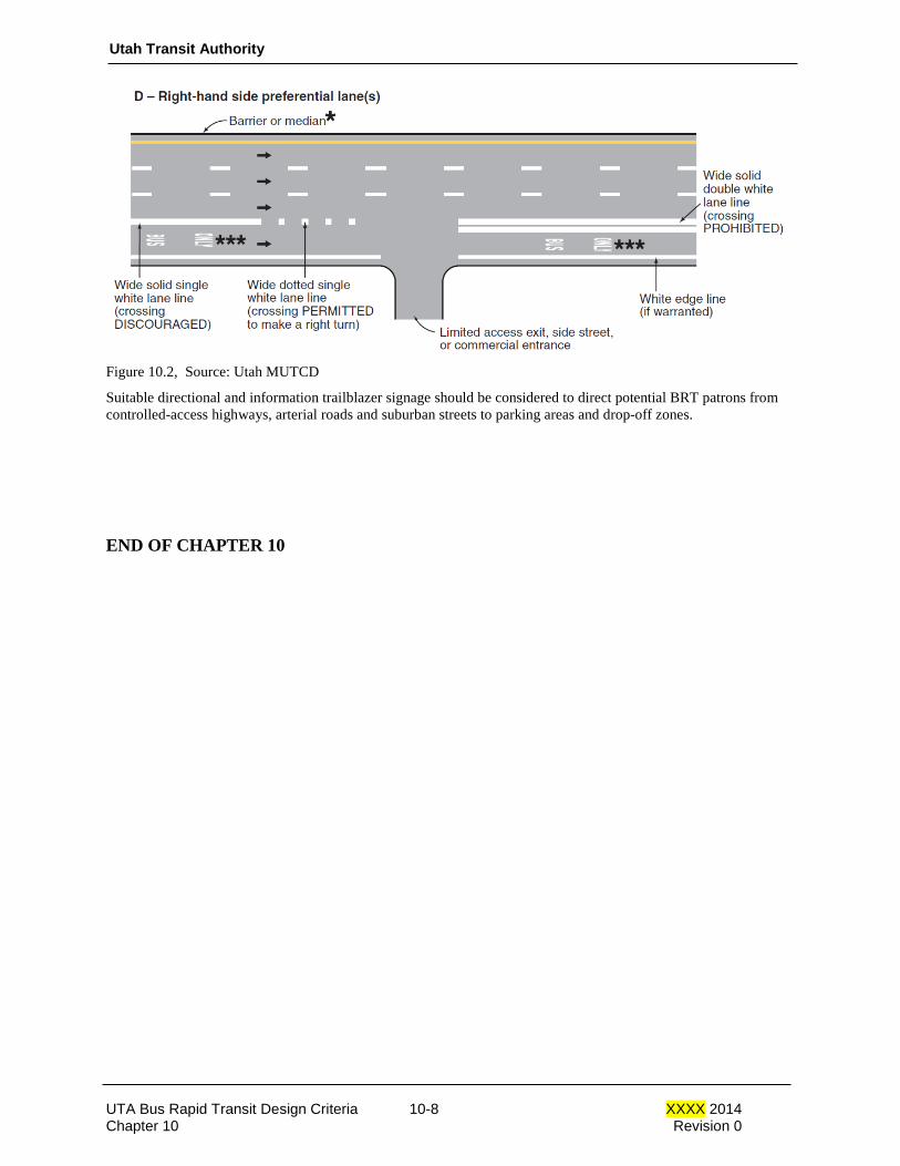
Utah Transit Authority
Figure 10.2, Source: Utah MUTCD
Suitable directional and information trailblazer signage should be considered to direct potential BRT patrons from controlled-access highways, arterial roads and suburban streets to parking areas and drop-off zones.
END OF CHAPTER 10
UTA Bus Rapid Transit Design Criteria 10-8 XXXX 2014 Chapter 10 Revision 0
APPENDIX A: UTA Blankout Sign Specifications
The following define the physical and operational characteristics required for the electronic blankout signs used by UTA as part of their safety and awareness program. This specification is both general and specific in nature, attempting to cover general elements applicable to all the various signs in use by UTA, while also addressing specific items required for each of the sign types.
The signs covered by this specification include (but are not limited to) the following sign types currently in use by UTA. This specification is intended to be applied – generally – to other, new signs that may be needed in the future, with the recognition that such signs will have different sizing, displayed images, or functional requirements.
• R3-1 (No Right Turn), 24x24, 120vAC
• R3-2 (No Left Turn), 24x24, 120vAC
GENERAL
All signs use only LED’s for all light generation. No bulbs, fiber optics, or other sources are allowed.
All signs are reproductions of MUTCD standard signage (sign identifier provided above) or are UTA modifications of the same.
All signs will run on 120vAC source power up to the sign, with any voltage transformation taking place in the sign, unless specified otherwise.
All signs will present a ‘solid-face’ display; no Pixelated or Dot-Matrix appearance (individual LED’s visible) will be allowed.
All signs will have self-regulated, progressive dimming to control LED intensity output based on ambient external light conditions, and controlled by a photo-diode built into the face of the sign.
All signs will have the following options with regard to multi-part messages and flashing/solid operation:
- Up to 4 unique ‘parts’ or messages may be independently controlled (solid or flashing) with their own power source (ie, a 5-conductor cable may control 4 unique sign displays within the same housing).
- Sign will show a solid or flashing display, using an internal flash relay in the sign, with no external input required to flash the sign. This is to be an OPTION that may be specified for specific signs.
- Sign will show a solid or flashing display based on supplied voltage being solid or flashing. Capacitor-based voltage regulation must be addressed to meet this requirement.
All signs will meet the requirements of the “Federal Standards – Highway Signs Handbook” with regard to legibility distance, viewing angles, and legibility under different lighting conditions.
All signs will be fully functional in the temperature range of (-35 F) to (+165 F), and in the voltage range of (90vAC) to (130vAC), unless otherwise specified for specific sign types.
** Signs will be warranted by the manufacturer for a minimum of 3 years from date of shipment.
ENCLOSURE
All parts of the sign enclosure will be manufactured from aluminum 5052 or 6061.
All enclosure surfaces – inside and out – will be matte black, powder coated (baked). Painted surfaces will not be allowed.
The faceplate or door will be hinged for self-supporting access to the interior of the sign.
The faceplate or door will be held closed using a minimum of 2 snap-lock latches. These latches will be able to be opened without the use of any tools or hardware – fingers only.
The faceplate or door will be sealed – when closed – to prevent moisture entry.
UTA Bus Rapid Transit Design Criteria 10-9 June 2014 Chapter 10 Revision 0
Utah Transit Authority
All access holes for wiring will be:
1) Protected on all cut edges to prevent cable fray (grommets or EMT fittings)
2) Sealable to prevent moisture and bug entry.
3) Accessible through the rear of the sign, preferably through the sign mount itself. Loose hanging cables outside the sign will not be allowed.
The sign enclosure will have at least 2 weep holes (or multiple louvers) for moisture escape at the bottom of the sign. These holes will be protected against insect entry.
The signs will come with factory provided / assembled mounting equipment, capable of mounting to either a horizontal signal mast arm (or equivalent) or a vertical signal pole (or equivalent). The mount will utilize slip-poles, rotational base/mount, and slippable cables similar to the Astro-Brac product typically used in the traffic signal industry. Gooseneck or nipple mountings will not be allowed.
The faceplate or display will be constructed using a black, powder coated backing plate with a UV protected, polycarbonate shield for LED diffusion. Individual LED’s visible through the faceplate will not be allowed (ie, no Dot-Matrix appearance).
LED SPECIFICATIONS
LED’s used for the signs will be 5mm or greater, and conform to the following for life expectancy (20% degradation) and other characteristics:
- AllnGaP (yellow, orange, and red)
- InGaN (green)
- YAG CE phosphor (white)
Operational characteristics for the LED’s will be as follows:
Color Wavelength Lums @ 20ma Viewing Angle
Green 520nm 4180mcd 30 deg
Yellow 590nm 4180mcd 30 deg
Red 626nm 4180mcd 30 deg
White x=0.31 / y=0.32 4100mcd 40 deg
LED’s will be mounted directly to the backing plate at no more than (0.5”) centers.
Power consumption will be no more than 4 watts per 100 LED’s (yellow, orange, red) and 8 watts per 100 LED’s (white and green).
UTA Bus Rapid Transit Design Criteria 10-10 June 2014 Chapter 10 Revision 0

Utah Transit Authority
R3-1 (No Right Turn), 24x24, 120vAC
Specific Elements For This Sign:
This sign is to be a minimum of 2-colors, as shown here, against a solid black background.
All elements of the sign are to be solid (no dot-matrix visible).
Dimensions (24”x24”) are for the display face, not the full enclosure.
This sign will (typically) be required to have an internal flash-relay, 1hz rate.
R3-2 (No Left Turn), 24x24, 120vAC
Specific Elements For This Sign:
This sign is to be a minimum of 2-colors, as shown here, against a solid black background.
All elements of the sign are to be solid (no dot-matrix visible).
Dimensions (24”x24”) are for the display face, not the full enclosure.
This sign will (typically) be required to have an internal flash-relay, 1hz rate.
UTA Bus Rapid Transit Design Criteria 10-11 June 2014 Chapter 10 Revision 0

Design Criteria UTA Bus Rapid Transit
Rev No. Prepared By Approved
By Approval Date
Document Date
0 T.W. Jones 2014
Utah Transit Authority Bus Rapid Transit
Design Criteria
Chapter 11 Bus Rapid Transit Vehicles
XXXX 2014
Utah Transit Authority
Table of Contents
CHAPTER 11 BUS RAPID TRANSIT VEHICLE ............................................................................ 1
11.1 General Description ......................................................................................................................... 1
11.2 Vehicle Configuration ...................................................................................................................... 1
11.2.1 60’ Articulated Bus ............................................................................................................. 1 11.2.1.1 Dimensions ...................................................................................................... 1 11.2.1.2 Doors ............................................................................................................... 1
11.2.2 40’ Standard Bus ................................................................................................................. 1 11.2.2.1 Dimensions ...................................................................................................... 1 11.2.2.2 Doors ............................................................................................................... 1
11.3 Boarding and Alighting .................................................................................................................... 1
11.4 Vehicle Finishes ............................................................................................................................... 2
UTA Light Rail Design Criteria 11-i November 2007 Chapter 11 Revision 4

Utah Transit Authority
CHAPTER 11 BUS RAPID TRANSIT VEHICLE
11.1 General Description This section describes the basic attributes of the Bus Rapid Transit vehicles to be used by UTA. The UTA BRT fleet will include two vehicle sizes: a 60’ articulated bus and a 40’ standard bus. The selection of vehicle size will be based on the ridership demand of a particular corridor.
11.2 Vehicle Configuration
11.2.1 60’ Articulated Bus 11.2.1.1 Dimensions Typical dimensions of BRT vehicles are shown in table 11.1. Refer to UTA BRT Design Criteria Chapter 5 for bus turning template. 11.2.1.2 Doors All 60’ articulated busses in the BRT fleet shall accommodate both right side and left side boarding. The standard door configuration is three right side doors and two left side doors.
11.2.2 40’ Standard Bus 11.2.2.1 Dimensions Typical dimensions of BRT vehicles are shown in table 11.1. Refer to UTA BRT Design Criteria Chapter 5 for bus turning template. 11.2.2.2 Doors All 40’ standard busses in the BRT fleet shall have a minimum of three doors
Typical BRT Vehicle Dimensions
60' Articulated Bus 40' Standard Bus
Max. Height* 140 in 140 in Width 102 in 102 in Length 59 to 65 ft 40 ft to 44ft, 11in
Typical Step Height 14 in 14 in Table 11.1 Typical BRT Dimensions
11.3 Boarding and Alighting Throughout sections with a Type II, Type III or Type IV Running Way, all station platforms will be raised to accommodate level boarding. Refer to Chapter 8 for station design. The typical width of gap between the busses and the platform as busses dock at stations ranges between 3 in. and 9 in. To ensure access for mobility challenged patrons, busses shall be equipped with at least one passenger deployable bridgeplate that will span the gap between the bus and the platform. When deployed to boarding and alighting surface, the slope of the bridgeplate shall not exceed 6:1.
UTA Light Rail Design Criteria 11-1 November 2007 Chapter 11 Revision 4
Utah Transit Authority
In addition to the passenger deployable bridgeplate for loading at raised platforms, each bus must also be equipped with a ramp or lift that will accommodate boarding and alighting from the roadway surface to enable accessible loading and alighting in off route areas. The ramp shall be capable of deploying to the ground at a maximum 6:1 slope. This may be either passenger deployable or operator deployable. Any ramp or lift shall comply with all current ADA requirements.
11.4 Vehicle Finishes To differentiate the BRT system from the standard bus service, all BRT vehicles will follow UTA’s BRT branding scheme. This includes the color scheme of the vehicle exteriors as well as on board passenger amenities. Coordinate with the UTA Public Relations Department for the most current branding design. The vehicles will also incorporate enhancements to improve the aesthetic design, such as larger windows for increased lighting and interior materials and finishes that suggest superior service. The seat layouts will also include wider aisles for better circulation. Additionally, the 60’ articulated busses will include bicycle boarding areas. END OF CHAPTER 11.
UTA BRT Design Criteria 11-2 XXXX 2014 Chapter 11 Revision 0

Design Criteria UTA BRT
Rev No.
Prepared By
Approved By
Approval Date
Document Date
0 2014
Utah Transit Authority Bus Rapid Transit
Design Criteria
Chapter 14 Communications
XXXX 2014
Utah Transit Authority
Table of Contents
CHAPTER 14 COMMUNICATIONS ................................................................................................ 1
14.1 General ............................................................................................................................................ 1 14.1.1 Electromagnetic Interference (EMI) ................................................................................... 1 14.1.2 Installation, Testing, Manuals, and Training ...................................................................... 1 14.1.3 Warranty and Initial Provisioning ....................................................................................... 1 14.1.4 Communications Interfaces ................................................................................................ 1
14.2 Two-Way Radio ................................................................................................................................ 2 14.2.1 System Description ............................................................................................................. 2 14.2.2 Vehicle Radios .................................................................................................................... 2 14.2.3 Mobiles and Portable Radios .............................................................................................. 2
14.3 Communications Transmission System ............................................................................................ 2 14.3.1 Fiber Optic Communication System ................................................................................... 2 14.3.1.1 BRT Line Fiber Optic Conduit Duct Bank ........................................................................ 2 14.3.2 Microwave Transmission System ....................................................................................... 4
UTA BRT Design Criteria 14-i XXXX 2014 Chapter 14 Revision 0
Utah Transit Authority
CHAPTER 14 COMMUNICATIONS
14.1 General This chapter describes the functional requirements for communications and identifies important interface criteria to be used in the development of the final design specifications. Essential communications for BRT station electronics, signaling and Operations Control Center (OCC) dispatching office system, and the BRT bus progression system require a Fiber Optic Communication System. The primary elements of the Fiber Optic Communication System are:
a. BRT Line Fiber Optic Conduit Duct Bank b. BRT Station I.T. Data Fiber Optic Cable c. Signaling Communications Fiber Optic Cable d. Advanced Traffic Management (ATMS) Conduit Duct Bank and Fiber Optic Cable System
Voice radio communications will conform to the most recently installed radio system configuration approved by UTA Information Systems. The specifications for radios shall be defined by UTA Information Systems, in coordination with bus operations, and shall be a procurement contract which shall include commissioning, technical support and training. Field construction such as antenna installation and base station site provisions shall be covered under separate work. 14.1.1 Electromagnetic Interference (EMI) The system design shall mitigate any possible interference that could be caused by the communications system to other electrical systems such as signals and vehicles. 14.1.2 Installation, Testing, Manuals, and Training Field installation procedures that are consistent with industry practice and the radio manufacturer’s recommendations shall be employed. (All radio installations will be performed under UTA supervision at UTA facilities.) Actual testing in the factory and in the field shall be certified as being done in accordance with approved plans and procedures. Field tests must be witnessed. Factory tests may be witnessed at the discretion of UTA. Requirements for the publication of operating and maintenance (O&M) manuals as well as requirements for UTA personnel training shall be developed as necessary. 14.1.3 Warranty and Initial Provisioning Contractor warranty of in-service equipment shall be compulsory for a specified period such as 1 year after delivery, or after installation and acceptance testing. The required warranty period shall be stated in the contract provisions. During the development of preliminary and final specifications, a maintenance philosophy and the corresponding spares provisioning shall become evident. An allowance has been made for the initial provisioning based on the contractor’s recommendations. 14.1.4 Communications Interfaces The communications system design, construction, and testing activities must be fully interfaced with other project activities. The most significant interfaces with the communication system are with the BRT vehicles, BRT station electronics, signal system, and the operations control center (OCC). The communications contract shall provide for the design and furnishing of the train radios. The radios shall be installed in the vehicles under UTA supervision. Prototype tests interfacing with the vehicles shall be
UTA BRT Design Criteria 14-1 XXXX 2014 Chapter 14 Revision 0

Utah Transit Authority
required for any new or modified unit. Particular areas of concern are the requirements for mechanical installation, cabling, power supply, cab controls, antenna, and for interface with the signal system, cable transmission system, and the software changes needed to merge the BRT system with UTA’s existing radio dispatching system.
14.2 Two-Way Radio 14.2.1 System Description Two-way radio is mandatory for the communications between the train operator and the control center. This requirement can be met with the currently used and most recently installed radio system configuration. The radio system supporting UTA BRT will provide critical voice communications to field personnel, therefore the system must provide push-to-talk communications anytime and anywhere within the area of operation. This push-to-talk communication must act like a single system across all BRT sites, particularly for ‘all group’ calls. Additionally, the system shall support full duplex interconnectivity, fixed/mobile data services, short message service paging, and alphanumeric paging. Bus control by voice radio will occur at the start, end and during each run. Bus operators may be required to report by voice conversation or canned data message via the bus radio all schedule delays, using established procedures. Actual test measurements of coverage shall be conducted as required. 14.2.2 Vehicle Radios A panel mounted Mobile Communications Device (MCD) control head is planned for each cab on the BRT vehicle. Separate MCD radios, antennas, transmission lines, and power supplies shall be used for each cab configuration. A speaker shall permit the operator to monitor all radio conversation at the discretion of the dispatcher. A handset, when lifted, shall be used for talking and listening. The mobile radio equipment shall be installed in the BRT vehicles after UTA acceptance of the BRT vehicles. 14.2.3 Mobiles and Portable Radios Mobile and portable radio units shall be easy to use and will require minimal operator training. These radios shall operate in accordance with all features required in the vehicle mounted radios. This includes, but is not limited to, full duplex interconnect, push-to-talk, alphanumeric paging, packet data, and short message service.
14.3 Communications Transmission System 14.3.1 Fiber Optic Communication System
14.3.1.1 BRT Line Fiber Optic Conduit Duct Bank An exclusive use fiber optic conduit duct bank consisting of four 1.5” conduits will be provided along the entire length of the BRT corridor. The following color coded conduits will be used: red stripe on black, black, orange and grey. The I.T. data fiber optic cable shall be installed in the grey conduit and the 24 fiber signal communication optic cable shall be installed in the orange conduit. A detector wire shall be installed in the grey conduit for the length of the corridor. Pull boxes will be located every 2500 feet maximum along the duct bank run, or as designated in project drawings and at each equipment site.
UTA BRT Design Criteria 14-2 XXXX 2014 Chapter 14 Revision 0

Utah Transit Authority
Lateral conduit connections consisting of two 2” conduits will be placed from the duct bank to each BRT station power control cabinet (PCC), traffic signal controller (for future contingency purposes) and the operations control center (OCC).
14.3.1.2 BRT Station I.T. Data Fiber Optic Cable This fiber optic cable interconnects all of the BRT line’s stations to the headquarters I.T. data servers in order to process the ticket vending machine, fare card reader, passenger information, CCTV data, etc. All fibers of this cable shall be routed into and out of the splice/patch panel of each BRT station power control cabinet. The fibers will be spliced through in the splice panel section or routed to the patch panel per the fiber cable schedule design document. A rack-mounted splice/patch panel such as the Leviton Model RDP-700 or equivalent shall be supplied and installed. Also 12 port patch panel fiber connector assemblies using SC connectors shall be provided. Refer to Chapter 8 Station Section 8.3.7 Communication and Power Conduits for additional description and requirements. Refer to Chapter 15 Fare Collection Equipment Section 15.2.4.9 TVM Communications and Section 15.2.5.10 Card Reader Communications for additional requirements.
14.3.1.3 Signaling Communications Fiber Optic Cable – (24 Single Mode Fibers) This fiber optic cable supports the Signaling System communications with the BRT line’s Operations Control Center.. Fibers 1 through 16 of this cable are allocated to signaling communications and interconnecting all signal equipment houses with the BRT line’s Operations Control Center to support train control and dispatcher functions. Fibers 17 through 24 of this cable are for future expansion and communications needs. All 24 fibers of this cable shall be routed into and out of the splice/patch panel of every signal equipment house on the LRT line’s alignment. The fibers will be spliced through in the splice panel section or routed to the patch panel per the fiber cable schedule design document. Wall mounted Corning Model WCH-06P Splice/Patch Panels or equivalent will be supplied and installed. Also 8 port patch panel fiber connector assemblies using ST connectors shall be provided. 14.3.1.4 Advanced Traffic Management (ATMS) Conduit Duct Bank and Fiber Optic Cable System A separate Advanced Traffic Management (ATMS) conduit duck bank and its companion ATMS fiber optic cable will be required in all BRT running ways. This ATMS fiber optic cable using the separate ATMS conduit duct bank interconnects each of the traffic signal controllers with the UDOT and SLC Traffic Control Centers (as appropriate) to support traffic management functions. A 6 fiber lateral cable shall be terminated in each traffic signal controller and will be spliced into the main ATMS cable at the appropriate conduit duct bank pull box.
UTA BRT Design Criteria 14-3 XXXX 2014 Chapter 14 Revision 0
Utah Transit Authority
The ATMS conduit duct bank and its companion ATM fiber optic cable shall be compliant with UDOT’s latest specifications. Refer to Chapter 10 “Traffic Control and BRT Signal Priority System” for additional description and requirements. 14.3.1.5 As-Built Drawings Clearly labeled and accurate As-Built drawings shall be provided showing the paths of required conduits, location of hand holes, and designated locations of ticket vending machines, card readers, phones, passenger information signs, IP security cameras, stand-alone message signs, light poles, camera poles, kiosks, and map cases.
14.3.2 Microwave Transmission System Where communications are required where the BRT operates in mixed flow (Type I) on a facility under the jurisdiction of UDOT or local agency, UTA maintenance and operations facilities and the CCF shall be interconnected via UTA’s existing digital microwave system. The quantity of new microwave channels to be supplied shall be consistent with the UTA’s operating requirements for that location. The microwave system may carry UTA’s radio audio. All new microwave equipment shall be of the same manufacturer and model number as the UTA’s existing equipment and shall be installed to support a ‘ring’ configuration whenever possible. END OF CHAPTER 14.
UTA BRT Design Criteria 14-4 XXXX 2014 Chapter 14 Revision 0

Design Criteria UTA BRT
Rev No. Prepared By Approved By Approval Date
Document Date
0 T. W. Jones 2014
Utah Transit Authority Bus Rapid Transit
Design Criteria
Chapter 15 Fare Collection Equipment
XXXX 2014

Utah Transit Authority
Table of Contents
CHAPTER 15 FARE COLLECTION EQUIPMENT ....................................................................... 1
15.1 General ............................................................................................................................................ 1
15.1.1 Conditions of Service .......................................................................................................... 1 15.1.2 Handicapped Accessibility .................................................................................................. 1
15.2 Functions of Fare Collection Equipment ......................................................................................... 2
15.2.1 General ................................................................................................................................ 2 15.2.2 Power Supply ...................................................................................................................... 3 15.2.3 Mounting ............................................................................................................................. 3 15.2.4 Functions of TVMs ............................................................................................................. 3
15.2.4.1 Tariff .................................................................................................................... 3 15.2.4.2 Vending ................................................................................................................ 3 15.2.4.3 Coin Handling ...................................................................................................... 3 15.2.4.4 Bill Handling ........................................................................................................ 4 15.2.4.5 Tickets .................................................................................................................. 4 15.2.4.6 Protection Against Theft....................................................................................... 5 15.2.4.7 Other Design Requirements ................................................................................. 5 15.2.4.8 Failure Modes ....................................................................................................... 6
15.2.5 Functions of Card Readers .................................................................................................. 6 15.2.5.1 General ................................................................................................................. 6 15.2.5.2 Power Supply ....................................................................................................... 7 15.2.5.3 Mounting .............................................................................................................. 7 15.2.5.4 Tariff .................................................................................................................... 7 15.2.5.5 Vending ................................................................................................................ 7 15.2.5.6 Fare Validation ..................................................................................................... 7 15.2.5.7 Protection Against Theft....................................................................................... 8 15.2.5.8 Other Design Requirements ................................................................................. 8 15.2.5.9 Failure Modes ....................................................................................................... 8
UTA Bus Rapid Transit Design Criteria 15-i XXXX 2014 Chapter 15 Revision 0

Utah Transit Authority
CHAPTER 15 FARE COLLECTION EQUIPMENT
15.1 General Patrons shall buy tickets and passes or use transfers for passage on the Bus Rapid Transit system. The ticket, pass, or transfer, in each case, evidences payment of fare and enables barrier-free fare control throughout the BRT system. Fare collection will occur off-board, and no fares or currency shall be collected aboard BRT busses. Self-service ticket vending machines (TVMs), located on BRT station platforms, shall accept credit cards, make change, and vend single ride tickets and day passes, with the future capability of vending multi-trip tickets and validating tickets. Card readers, providing Near Field Communications, located on BRT station platforms, shall provide for the use of Smart Card credit cards, employee cards and student ID cards in payment of fares. These card readers shall provide for Tap-On, Tap-Off ridership and the backend shall be configured so that riders may change modes of UTA transportation with a single Tap-On and Tap-Off. In addition to the card readers on the platforms, each BRT bus shall have a “Tap-On, Tap-Off” card reader located at each door.
15.1.1 Conditions of Service Fare collection equipment shall be capable of satisfactory operation in the ambient conditions described in paragraph four below. The front plate of the TVM shall have the capability to display permanent and contemporary information for passengers. The front plate of the card reader will show which credit cards it will accept, the card reader will have a numbered ID label, and a Braille label to identify it. The equipment shall be installed in locations with clear view from all directions and may be exposed to the weather and ambient conditions, including exposure to sunlight, snow and rain. Installations shall be at unmanned passenger stations and at sidewalk locations on existing streets which shall be exposed to the general public. Fare collection equipment shall be capable of maintaining operation within the climatic conditions as defined in Chapter 1 of the UTA BRT Design Criteria. All facilities shall be designed to accommodate safe storage and/or removal of snow, melting snow, and ice.
15.1.2 Handicapped Accessibility Fare collection equipment shall comply with the requirements of 49 CFR Parts 27, 37, and 30 implementing the provisions of the Americans with Disabilities Act of 1990 (ADA-90) as follows:
• Each machine shall be on an accessible route to the station.
• Controls for user activation shall comply with the following requirements:
– Clear Floor Space—Clear floor space that allows a parallel approach by a person using a wheelchair shall be provided at controls, dispensers, receptacles, and other operable equipment.
UTA Bus Rapid Transit Design Criteria 15-1 XXXX 2014 Chapter 15 Revision 0
Utah Transit Authority
– Size and Approach—The minimum clear floor or ground space required to accommodate a single, stationary wheelchair and occupant is 30 inches by 48 inches. The minimum clear floor or ground space for wheelchairs may be positioned for forward or parallel approach to an object.
– Relationship of Maneuvering Clearance to Wheelchair Spaces—One full unobstructed side of the clear floor or ground space for a wheelchair shall adjoin or overlap an accessible route or adjoin another wheelchair clear floor space.
• The highest operable part of controls, dispensers, receptacles, and other operable equipment shall be placed within at least one of the reach ranges specified below:
– Forward Reach—If the clear floor space only allows forward approach to an object, the maximum high forward reach allowed shall be 48 inches. The minimum low forward reach is 15 inches.
– Side Reach—If the clear floor space allows parallel approach by a person in a wheelchair, the maximum high side reach allowed shall be 54 inches and the low side reach shall be no less than 9 inches.
• Controls and operating mechanism shall be operable with one hand and shall not require tight grasping, pinching, or twisting of the wrist. The force required to activate controls shall be not greater than 5 pounds (22.2 N).
• Instructions and all information for use shall be made accessible to and independently usable by persons with vision impairments.
15.2 Functions of Fare Collection Equipment
15.2.1 General Fare collection equipment shall be standard production models of each type of equipment that is in use, which shall have a certifiable record of reliable, low maintenance operation on one or more existing transit systems under service conditions similar to those indicated herein for a period of not less than the past 3 years. The components of all fare collection equipment shall be modules capable of field replacement. All types of fare collection equipment in use shall have a certifiable record of satisfactory performance on similar types of installation. The failure rate shall not exceed 1.5 failures per month for each type of equipment in use (i.e., the number of failures in each 3-month period divided by the number of units in the equipment group shall yield a quotient not greater than 4.5), nor shall the failure rate exceed 1 per 8,000 transactions completed (i.e., the number of failures in each 3-month period when multiplied by the number 8000 and that product divided by the total number of transactions completed by all units in the equipment group shall yield a quotient not greater than unity) Listing and labeling of all fare collection equipment shall conform to the following:
• For fare collection equipment of U.S. manufacture, each type of fare collection equipment in use shall comply with the standards of a testing organization nationally recognized in the United States, such as UL.
• For fare collection equipment of foreign manufacture, a certificate or other evidence that the equipment is in compliance with the standards of a testing organization which is nationally recognized in the country of manufacture.
UTA Bus Rapid Transit Design Criteria 15-2 XXXX 2014 Chapter 15 Revision 0

Utah Transit Authority
15.2.2 Power Supply Fare collection equipment shall operate on primary power from a single phase, 120-V, 60-Hz service having a voltage variation of +10% and −15%. Power shall enter the base of the equipment.
15.2.3 Mounting Each type of fare collection equipment shall include a base, either integral or separate as a pedestal, suitable for mounting to a concrete footing or floor.
15.2.4 Functions of TVMs 15.2.4.1 Tariff The TVM shall vend tickets ranging in value from $0.05 to $99.95 at selected $0.05 increments. The value of any ticket in the tariff shall be adjustable by UTA to accommodate tariff revisions on each TVM installed and in service. The number of values in the tariff shall be at least 32. 15.2.4.2 Vending A passenger shall select a ticket or multiples of the same ticket by pressing a corresponding push-button on the selection keyboard. An LCD display, with backlighting or equivalent, easily distinguishable in sunlight, shall show the correct fare for the ticket selected. Alternatively, a 9-inch diagonal programmable LCD screen with backlighting or equivalent easily distinguishable in sunlight, may be provided to direct the customer through the steps of the transaction, with the customer’s responses being entered through function keys as in ATM operations. The screen shall be capable of displaying 40 alphanumeric characters per line and up to 25 lines at a time and shall be shaded from direct sunlight by means of a hood or optical filter. A passenger may deposit a single bill and/or multiple coins in the TVM and the display shall decrease to zero as money is inserted. When the money is sufficient to pay the fare, as shall occur when the display reaches zero, the TVM shall automatically print and vend the ticket selected. Change shall be provided. In the event a passenger decides to discontinue the payment after selection and before the display decreases to zero, he/she may do so by depressing the cancel button on the face of the TVM. The TVM shall then return the amount of money the passenger has deposited. In the event a passenger simply discontinues payment of the selection before the display decreases to zero, the TVM shall self cancel in the manner indicated above after a period adjustable from 10 to 60 seconds. 15.2.4.3 Coin Handling A single vertically oriented coin slot shall be provided. The coin slot shall be closed normally except when vending is enabled. The following U.S. coins shall be accepted:
Diameter
Thickness
Weight
Half-dollar (50¢) 1.205″ 0.086″ 11.30 g Quarter (25¢) 0.955″ 0.067″ 5.67 g Dime (10¢) 0.705″ 0.053″ 2.268 g
UTA Bus Rapid Transit Design Criteria 15-3 XXXX 2014 Chapter 15 Revision 0
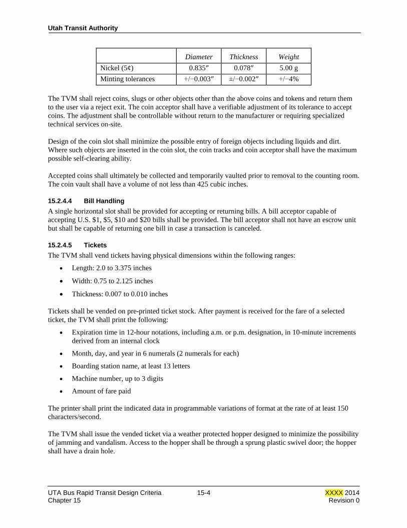
Utah Transit Authority
Diameter
Thickness
Weight
Nickel (5¢) 0.835″ 0.078″ 5.00 g Minting tolerances +/−0.003″ ±/−0.002″ +/−4%
The TVM shall reject coins, slugs or other objects other than the above coins and tokens and return them to the user via a reject exit. The coin acceptor shall have a verifiable adjustment of its tolerance to accept coins. The adjustment shall be controllable without return to the manufacturer or requiring specialized technical services on-site. Design of the coin slot shall minimize the possible entry of foreign objects including liquids and dirt. Where such objects are inserted in the coin slot, the coin tracks and coin acceptor shall have the maximum possible self-clearing ability. Accepted coins shall ultimately be collected and temporarily vaulted prior to removal to the counting room. The coin vault shall have a volume of not less than 425 cubic inches. 15.2.4.4 Bill Handling A single horizontal slot shall be provided for accepting or returning bills. A bill acceptor capable of accepting U.S. $1, $5, $10 and $20 bills shall be provided. The bill acceptor shall not have an escrow unit but shall be capable of returning one bill in case a transaction is canceled. 15.2.4.5 Tickets The TVM shall vend tickets having physical dimensions within the following ranges:
• Length: 2.0 to 3.375 inches
• Width: 0.75 to 2.125 inches
• Thickness: 0.007 to 0.010 inches Tickets shall be vended on pre-printed ticket stock. After payment is received for the fare of a selected ticket, the TVM shall print the following:
• Expiration time in 12-hour notations, including a.m. or p.m. designation, in 10-minute increments derived from an internal clock
• Month, day, and year in 6 numerals (2 numerals for each)
• Boarding station name, at least 13 letters
• Machine number, up to 3 digits
• Amount of fare paid The printer shall print the indicated data in programmable variations of format at the rate of at least 150 characters/second. The TVM shall issue the vended ticket via a weather protected hopper designed to minimize the possibility of jamming and vandalism. Access to the hopper shall be through a sprung plastic swivel door; the hopper shall have a drain hole.
UTA Bus Rapid Transit Design Criteria 15-4 XXXX 2014 Chapter 15 Revision 0

Utah Transit Authority
15.2.4.6 Protection Against Theft The design of the TVM shall provide separate secure locked access to the interior for maintenance and separately to the money. Each access on each TVM shall be by a lock designed to minimize vandalism and theft. The locks to each access on any TVM shall be keyed differently according to function. However, all TVMs shall be keyed alike. All keys shall be controlled and registered equivalent to level IV, Medeco Security Locks, Inc.1 All locks shall be flush mounted. Two coin and bill vaults shall be provided for each TVM. One vault shall normally be in service in each TVM. The second vault shall be used in rotation for revenue collections. Each vault shall have security from access such that, when removed from the TVM, it is automatically locked. Additional spare vaults shall be required for use during service and maintenance of the two base vaults. Each vault shall be fitted with a device that is encoded with a number unique to that container. The device shall be used by the TVM to automatically identify the vault serial number. In addition, each vault shall be individually identified by a unique, permanently inscribed serial number. The inscribed serial number shall be identical to the number automatically readable by the TVM. The total amount of money by denomination deposited into a vault shall be monitored from the time the vault is inserted in the TVM. This monitoring shall allow the contents to be reported when the vault is replaced and prevent the vault from overfilling without warning. The TVM shall be constructed to enhance protection against theft. All screws shall be covered over. All hinges shall be covered over or constructed so as to prevent entry by drilling. All exterior seams shall be overlapping. The design shall provide for a set of contacts to enable a local security alarm in the event unauthorized tampering opens any access door more than 0.08 in. An internal klaxon, or equivalent device, shall locally annunciate the security alarm. A switch shall be provided to select enablement or suppression of the klaxon. 15.2.4.7 Other Design Requirements The TVM shall have interlocks such that the coin and bill slots shall close and an out-of-service sign shall be shown or illuminated if the TVM detects a bill, coin or paper jam, runs out of paper, or any other malfunction which shall completely disable the TVM. The TVM shall be provided with an internal battery to operate its clock during a power interruption of up to 6 hours. The TVM shall accumulate and summarize data to enable audit of vending transactions occurring between vault replacements. These data shall include:
1Medeco Security Locks, P.O. Box 1075, Salem, Virginia 24153-1075.
UTA Bus Rapid Transit Design Criteria 15-5 XXXX 2014 Chapter 15 Revision 0
Utah Transit Authority
• The number of vended tickets by ticket class
• Revenue collected by ticket class
• The sum of all vended tickets and total revenue collected The TVM shall generate and imprint an audit ticket with these data. The audit ticket shall be suitable for inserting in the vaults removed when replaced for purposes of the counting room’s audit. As an alternative to inserting the audit ticket in the vault, the TVM shall automatically generate the serial identification number of the removed vault either during removal or immediately following removal and before the replacement vault is inserted. The TVMs shall have a system which shall automatically and independently transfer the indicated audit data from each TVM for subsequent reading and processing on UTA’s central processor. Construction materials for the TVM shall be as defined below:
• The TVM shall use stainless steel for the construction of the base and the enclosure.
• All pushbuttons, function keys, and numeric keys on the exterior of the TVM shall be metal and shall not be removable from the exterior of the machine.
• All displays on the exterior of the TVM are to be protected by shatter resistant plexiglass or polycarbonate covers.
• Any messages to be permanently affixed to display windows are to be applied by silk screening.
• Construction and installation shall be in accordance with the requirements of the NEC. 15.2.4.8 Failure Modes In general, unless for cause of security, or for a transaction of improper value, the TVM shall fail gracefully (i.e., the mode of failure shall permit as much of the TVM to function as possible). In the event there is a failure of the commercial power energizing the TVM, the TVM shall lose no data, nor require reset of the clock, and for any transaction in progress, the TVM shall either allow the transaction to conclude, or cancel the transaction at the point of interruption. 15.2.4.9 TVM Communications A fiber optic network connects all Ticket Vending Machines (TVM) on all station platforms of an LRT line to a fare collection server at UTA Headquarters. This server supports workstations which provide monitoring and control functions in support of credit card transactions as well as revenue administration and TVM maintenance operations. Refer to Chapter 14, Communications, Section 14.3.1.2 BRT Station I.T. Data Fiber Optic Cable and Chapter 8, Stations, Section 8.3.7 Communication and Power Conduits. 15.2.5 Functions of Card Readers 15.2.5.1 General The Card Readers shall be a standard production model which shall have a certifiable record of reliable, low maintenance operation on one or more existing transit systems under service conditions similar to
UTA Bus Rapid Transit Design Criteria 15-6 XXXX 2014 Chapter 15 Revision 0
Utah Transit Authority
those indicated herein for a period not less than the past 3 years. The components of the Card Readers shall be modules capable of field replacement. The Card Readers shall have a certifiable record of satisfactory performance reliability on similar types of installations. The failure rate shall not exceed 1.5 per Card Reader per month (i.e, the number of failures in each 3-month period divided by the number of Card Readers in the group shall yield a quotient not greater than 4.5), nor shall the failure rate exceed 1 per 8,000 uses (i.e., the number of failures in each 3-month period when multiplied by the number 8,000 and that product divided by the total number of uses by all Card Readers in the group, shall yield a quotient not greater than unity). Listing and labeling of the Card Reader shall conform to the following:
• For Card Readers of U.S. manufacture: The Card Readers shall comply with the standards of a testing organization nationally recognized in the United States, such as UL.
• Card Readers of foreign manufacture: A certificate or other evidence that the Card Reader is in
compliance with the standards of a testing organization which is nationally recognized in the country of manufacture.
15.2.5.2 Power Supply The Card Readers shall operate on primary power from a single phase, 120-V, 60-Hz service having a voltage variation of +10% and -15%. Power shall enter the base of the Card Reader. 15.2.5.3 Mounting The Card Reader shall include a base, either integral or separate as a pedestal, suitable for mounting to a concrete footing or floor. 15.2.5.4 Tariff The Card Reader shall charge user card accounts using the most current tariff schedule applicable to Electronic Fare Collection. The value of any fare in the Electronic Fare Collection tariff shall be adjustable by UTA to accommodate tariff revisions and expansions on each Card Reader installed and in service. The number of values in the Electronic Fare Collection tariff for Card Readers shall be adjusted from time to time to accommodate UTA business practices and the latest card technology. 15.2.5.5 Vending The Card Reader shall be capable of being certified to accept all major credit cards, specifically VISA, MasterCard, American Express, and Discover. The Card Reader shall also be capable of accepting all third party pre-paid cards issued by UTA partners such as employers, schools, and other third party card sources. The Card Reader shall be capable of downloading ‘hot lists’ and other developed front end processing software in order to properly screen or validate cards used in purchasing fares. Card Readers shall be capable of identifying single or multiple readings from the same card as separate and perhaps different fares as determined by the then current backend transaction processing in place. 15.2.5.6 Fare Validation The Card Readers shall not dispense pre-printed tickets. Validation of fare payment shall be accomplished by UTA Transit Police using a scanning device to scan the credit card used to pay the fare which will then display validation data on the scanner device.
UTA Bus Rapid Transit Design Criteria 15-7 XXXX 2014 Chapter 15 Revision 0

Utah Transit Authority
15.2.5.7 Protection Against Theft The design of the Card Reader shall provide secure locked access to the interior for maintenance. Access on each Card Reader shall be by a lock designed to minimize vandalism and theft. The locks to access any Card Reader shall be keyed differently from other equipment on the platform or station. However, all Card Readers shall be keyed alike. All keys shall be controlled and registered equivalent to level IV, Medeco Security Locks, Inc. All locks shall be flush mounted. The Card Reader shall be constructed to enhance protection against theft. All screws shall be covered over. All hinges shall be covered over or constructed so as to prevent entry by drilling. All exterior seams shall be overlapping. 15.2.5.8 Other Design Requirements The TVM shall be provided with an internal battery to operate its clock during a power interruption of up to 6 hours. Construction materials for the Card Reader shall be as defined below:
• The Card Reader shall use stainless steel for the construction of the base and the enclosure.
• Any push buttons, function keys, and numeric keys on the exterior of the Card Reader shall be metal and shall not be removable from the exterior of the machine.
• All displays on the exterior of the Card Reader are to be protected by shatter resistant Plexiglas or
polycarbonate covers.
• Any messages to be permanently affixed to display windows are to be applied by silk screening.
• Construction and installation shall be in accordance with the requirements of the NEC. 15.2.5.9 Failure Modes In general, unless for cause of security, or for a transaction of improper value, the Card Reader shall fail gracefully (i.e., the mode of failure shall permit as much of the Card Reader to function as possible). In the event there is a failure of the commercial power energizing the Card Reader, the Card Reader shall lose no data, nor require reset of the clock, and for any transaction in progress, the Card Reader shall either allow the transaction to conclude, or cancel the transaction at the point of interruption. 15.2.5.10 Card Reader Communications A fiber optic network connects all electronic fare collection card readers on all station platforms of an LRT line to a card reader server at UTA Headquarters. This server supports workstations which provide
UTA Bus Rapid Transit Design Criteria 15-8 XXXX 2014 Chapter 15 Revision 0
Utah Transit Authority
monitoring and control functions in support of credit card transactions as well as revenue administration and maintenance operations. Refer to Chapter 14, Communications, Section 14.3.1.2 BRT I.T. Data Fiber Optic Cable and Chapter 8, Stations, Section 8.3.7 Communication and Power Conduits. END OF CHAPTER 15.
UTA Bus Rapid Transit Design Criteria 15-9 XXXX 2014 Chapter 15 Revision 0

Design Criteria UTA Bus Rapid Transit
Rev No.
Prepared By
Approved By
Approval Date
Document Date
0 T.W. Jones 2014
Utah Transit Authority Bus Rapid Transit
Design Criteria
Chapter 20 Park and Ride Lots
XXXX 2014
Utah Transit Authority
Table of Contents
PARK AND RIDE LOTS ........................................................................................................................... 2
20.1 General ............................................................................................................................................ 2
20.1.1 Scope ................................................................................................................................................ 2
20.1.2 Codes and Standards ....................................................................................................................... 2
20.1.3 General Design Parameters ............................................................................................................. 2
20.2 Lighting ............................................................................................................................................ 3
20.3 General Park and Ride Site Design Guidelines ............................................................................... 3
20.3.1 Vehicular Entrances and Exits to Station Site Facilities .................................................................. 3
20.3.2 Kiss-and-Ride Facilities ................................................................................................................... 3
20.3.3 Park-and-Ride Facilities .................................................................................................................. 6
20.3.4 Motorcycle Parking .......................................................................................................................... 8
20.3.5 Bicycle Racks ................................................................................................................................... 8
20.3.6 Borders of Parking Areas ................................................................................................................. 8
20.3.7 Pedestrian Access ............................................................................................................................. 8
UTA Bus Rapid Transit Design Criteria 20-i XXXX 2014 Chapter 20 Revision 0
Utah Transit Authority
PARK AND RIDE LOTS
20.1 General
20.1.1 Scope
This section establishes specific guidelines and standards for the design of bus access, kiss-and-ride and park-and-ride facilities. Equipment, shelters, and signage used in Park and Ride Lots shall be the same system-wide and compatible with UTA’s identity. Deviations from standard design elements may be required for specific sites, but must be approved by UTA before design proceeds.
20.1.2 Codes and Standards
Applicable codes and standards include the most current edition of the following documents:
• American Public Works Association (APWA)
• American Association of State Highway and Transportation Officials (AASHTO)
o A Policy on Geometric Design of Highways and Streets
o Guide for the Development of Bicycle Facilities
o Guide for the Planning, Design, and Operation of Pedestrian Facilities
o Roadside Design Guide
• Utah Department of Transportation Standard and Supplemental Drawings and Specifications
• Applicable Local Jurisdictional Ordinances and Standard Drawings
• Americans with Disabilities Act (ADA) Where no provisions are made in the codes for particular features of the design the best civil engineering practice shall be followed, with the prior approval of UTA.
20.1.3 General Design Parameters The facilities must be able to serve the needs of patrons efficiently, economically, safely, conveniently, and comfortably. In designing the facilities, the anticipated growth and long-term life of the system shall be considered. Function and life cycle consideration are important, as are aesthetics and the overall quality and character of the facilities. Park and ride facility design shall be compatible in design with the immediate vicinity and reflective of the regional context of the Wasatch Front. In all segments, it is essential that great care be taken in coordinating final design with UTA, the affected communities and neighborhoods, adjacent property owners or developers, public agencies, or community groups having jurisdiction over or significant interest in the human environment and design of facilities at stations and along routes. Coordination with the development plans and master plans of local communities and neighborhoods is essential to blending the transit system into the urban fabric of the Wasatch Front, and in assuring that UTA needs and community needs are met.
UTA Bus Rapid Transit Design Criteria 20-2 XXXX 2014 Chapter 20 Revision 0

Utah Transit Authority
20.2 Lighting Refer to Chapter 8 of the UTA Bus Rapid Transit Design Criteria for the lighting design guidelines.
20.3 General Park and Ride Site Design Guidelines
20.3.1 Vehicular Entrances and Exits to Station Site Facilities
The design of entrances for motor vehicles shall take into consideration adjacent land uses by avoiding large unplanted, paved areas or dimensions that are out of scale compared to adjacent streets and structures. Curb cuts shall be minimized, while fulfilling the following requirements:
• Access is preferred from minor arterials and collectors.
• Access roadways to station sites should be designed to contain sufficient traffic storage capacity to meet expected transit patronage at peak times and to prevent backing up into public streets.
• Conflicts should be avoided between access roadways and large pedestrian movements.
• Access to a station site with more than 1,000 spaces should be from more than one street since the availability of several feeder routes is desirable.
• Access management shall be applied as much as possible. Access coordination with local jurisdictions and Utah Department of Transportation shall look to anticipate future road relocations or changes that can be anticipated within a reasonable time.
20.3.2 Kiss-and-Ride Facilities
Kiss-and-ride drop-off and short-term parking facilities in the station area shall:
• Allow easy movement to locations near the station platforms.
• Be separated from the long-term parking area.
• Have stall widths of 10 feet (min.) to ease quick vehicle movements in and out. Parking lot design and landscaping (see Chapter 9) may be subject to local jurisdictional requirements. Preferred parking arrangements for kiss-and-ride areas are in the following order of preference:
• Parallel to curb (see Figure 20-1)
• 45 degrees to the aisle (see Figure 20-2)
• 60 degrees to the aisle (see Figure 20-3) Figures 20-1 through 20-3 show recommended stall and aisle widths for the kiss-and ride area.
UTA Bus Rapid Transit Design Criteria 20-3 XXXX 2014 Chapter 20 Revision 0

Utah Transit Authority
Figure 20-1: Kiss-and-Ride Parking Arrangement Stall Layout Parallel to Curb
UTA Bus Rapid Transit Design Criteria 20-4 XXXX 2014 Chapter 20 Revision 0
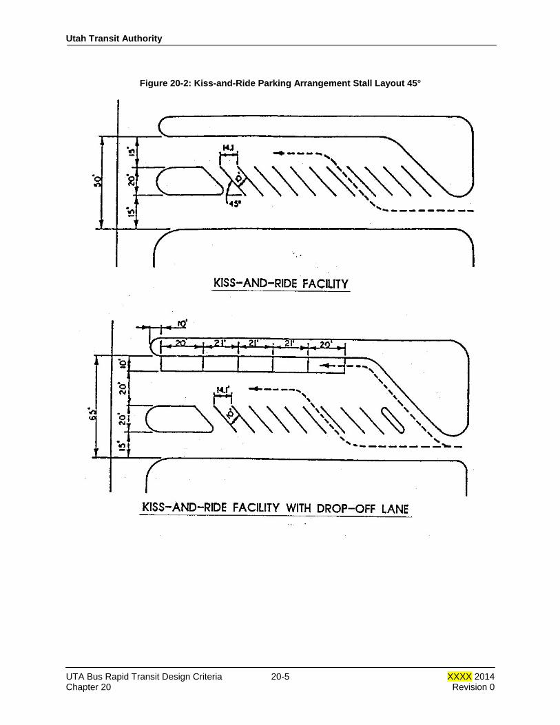
Utah Transit Authority
Figure 20-2: Kiss-and-Ride Parking Arrangement Stall Layout 45°
UTA Bus Rapid Transit Design Criteria 20-5 XXXX 2014 Chapter 20 Revision 0

Utah Transit Authority
Figure 20-3: Kiss-and-Ride Parking Arrangement Stall Layout 60°
20.3.3 Park-and-Ride Facilities
The park-and-ride areas shall be designed to optimize the site area allocated by using the concepts and dimensions shown on Figure 20-4, and outlined in the following sections. Design shall conform to local jurisdiction requirements. Refer to Chapter 5 of BRT Design Criteria to identify civil element criteria for the site work of the facility. Site work shall follow American Public Works Association or Utah Transit Authority standards and specifications wherever possible.
UTA Bus Rapid Transit Design Criteria 20-6 XXXX 2014 Chapter 20 Revision 0
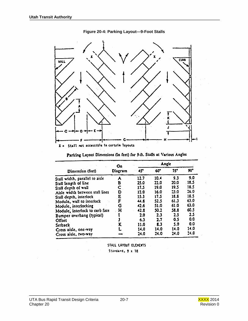
Utah Transit Authority
Figure 20-4: Parking Layout—9-Foot Stalls
UTA Bus Rapid Transit Design Criteria 20-7 XXXX 2014 Chapter 20 Revision 0
Utah Transit Authority
20.3.4 Motorcycle Parking Motorcycle parking stalls may be added in triangles and corners set off by the park-and-ride layout which are readily accessible to the station.
20.3.5 Bicycle Racks
Bicycle storage may be provided, as directed by UTA. Racks shall conform to the requirements listed below:
• Located so as to be readily visible
• Located to cause minimum interference with other station activities
• Provide a secure stanchion that allows bicycles to be locked Coordinate the location of the bicycle racks with UTA and the local jurisdiction.
20.3.6 Borders of Parking Areas
Parking lots should be designed to avoid the use of earth retaining structures, and to keep all work within UTA’s right-of-way lines. Curbs should be provided at all parking lot edges. Borders should be wide enough for landscaping and planting. Requirements for storm water management shall be considered in the design of the parking lot and border.
20.3.7 Pedestrian Access
Pedestrian circulation shall provide direct and convenient approaches to station platforms from off the site and from each of the individual sections of the lot. Parking aisle orientation shall be planned to consider pedestrian directness, lot capacity, and pedestrian safety. Pedestrian movements within the park-and-ride area will normally occur within the driving aisles. However, pedestrian walkways may be provided to minimize vehicular interference, to reduce the number of points where pedestrians cross the aisles, or to shorten irregular routes through successive aisles by a considerable distance. Pedestrian access to station platforms that cross train tracks shall conform to ADA requirements including providing a tactile warning surface. Storm water management shall conform to local jurisdiction requirements. END OF CHAPTER 20.
UTA Bus Rapid Transit Design Criteria 20-8 XXXX 2014 Chapter 20 Revision 0