Embed Size (px)
Citation preview
TRANSIT
RAPID TRANSIT SYSTEM EXTENSIONS COMPENDIUM OF DESIGN CRITERIA
VOLUME I SYSTEMWIDE DESIGN CRITERIA
CHAPTER 7
SYSTEM SAFETY DESIGN CRITERIA
INTERIM RELEASE REV 1
OCTOBER 30, 2008
PROGRAM MANAGEMENT CONSULTANT

– Intentionally Left Blank –

TRANSIT
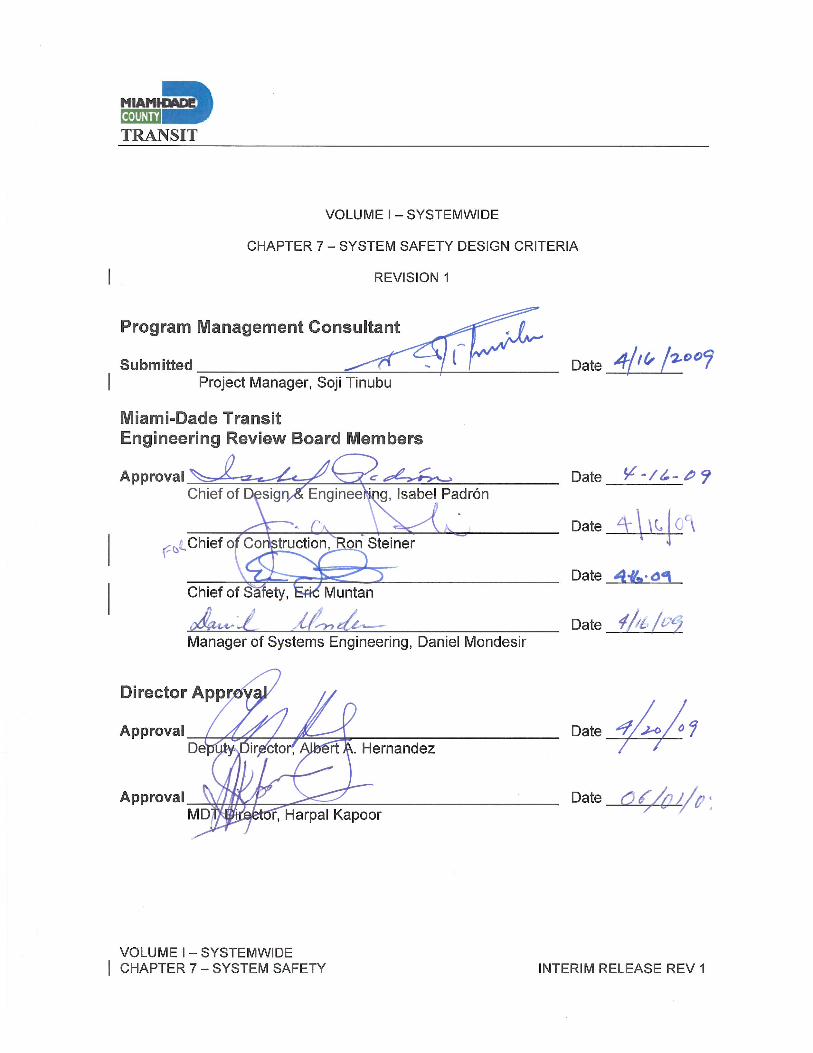
VOLUME I – SYSTEMWIDE CHAPTER 7 – SYSTEM SAFETY INTERIM RELEASE REV 1
– Intentionally Left Blank –
TRANSIT
VOLUME I – SYSTEMWIDE CHAPTER 7 – SYSTEM SAFETY INTERIM RELEASE REV 1
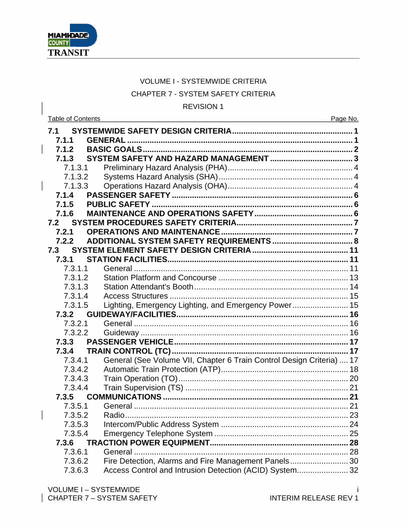
DOCUMENT REVISION RECORD
ISSUE NO. DATE REVISION DESCRIPTIONS
0 9-26-07 Interim Release
1 10-30-08 Revisions to incorporate MIC-EH design specifications that have been adopted by MDT.
ISSUE NO. SECTIONS CHANGED
1 7.1.1 Systemwide Safety - General
7.3.1.1 C System Element – Station Facilities – General
7.3.1.3 System Element – Station Facilities – Station Attendant’s Booth
7.3.5.1 Communications – General – Central Control Console
7.3.6.2 System Element – Station Facilities – Fire Detection Alarms and Fire Management Panels

TRANSIT
VOLUME I – SYSTEMWIDE CHAPTER 7 – SYSTEM SAFETY INTERIM RELEASE REV 1
– Intentionally Left Blank –
TRANSIT
VOLUME I – SYSTEMWIDE i CHAPTER 7 – SYSTEM SAFETY INTERIM RELEASE REV 1
VOLUME I - SYSTEMWIDE CRITERIA
CHAPTER 7 - SYSTEM SAFETY CRITERIA
REVISION 1 Table of Contents Page No.
7.1 SYSTEMWIDE SAFETY DESIGN CRITERIA...................................................... 1 7.1.1 GENERAL ..................................................................................................... 1 7.1.2 BASIC GOALS.............................................................................................. 2 7.1.3 SYSTEM SAFETY AND HAZARD MANAGEMENT ..................................... 3
7.1.3.1 Preliminary Hazard Analysis (PHA)........................................................ 4 7.1.3.2 Systems Hazard Analysis (SHA)............................................................ 4 7.1.3.3 Operations Hazard Analysis (OHA)........................................................ 4
7.1.4 PASSENGER SAFETY ................................................................................. 6 7.1.5 PUBLIC SAFETY .......................................................................................... 6 7.1.6 MAINTENANCE AND OPERATIONS SAFETY............................................ 6
7.2 SYSTEM PROCEDURES SAFETY CRITERIA.................................................... 7 7.2.1 OPERATIONS AND MAINTENANCE........................................................... 7 7.2.2 ADDITIONAL SYSTEM SAFETY REQUIREMENTS .................................... 8
7.3 SYSTEM ELEMENT SAFETY DESIGN CRITERIA ........................................... 11 7.3.1 STATION FACILITIES................................................................................. 11
7.3.1.1 General ................................................................................................ 11 7.3.1.2 Station Platform and Concourse .......................................................... 13 7.3.1.3 Station Attendant's Booth..................................................................... 14 7.3.1.4 Access Structures ................................................................................ 15 7.3.1.5 Lighting, Emergency Lighting, and Emergency Power ......................... 15
7.3.2 GUIDEWAY/FACILITIES............................................................................. 16 7.3.2.1 General ................................................................................................ 16 7.3.2.2 Guideway ............................................................................................. 16
7.3.3 PASSENGER VEHICLE.............................................................................. 17 7.3.4 TRAIN CONTROL (TC) ............................................................................... 17
7.3.4.1 General (See Volume VII, Chapter 6 Train Control Design Criteria) .... 17 7.3.4.2 Automatic Train Protection (ATP)......................................................... 18 7.3.4.3 Train Operation (TO) ............................................................................ 20 7.3.4.4 Train Supervision (TS) ......................................................................... 21
7.3.5 COMMUNICATIONS ................................................................................... 21 7.3.5.1 General ................................................................................................ 21 7.3.5.2 Radio.................................................................................................... 23 7.3.5.3 Intercom/Public Address System ......................................................... 24 7.3.5.4 Emergency Telephone System ............................................................ 25
7.3.6 TRACTION POWER EQUIPMENT.............................................................. 28 7.3.6.1 General ................................................................................................ 28 7.3.6.2 Fire Detection, Alarms and Fire Management Panels .......................... 30 7.3.6.3 Access Control and Intrusion Detection (ACID) System....................... 32
TRANSIT
VOLUME I – SYSTEMWIDE ii CHAPTER 7 – SYSTEM SAFETY INTERIM RELEASE REV 1
7.3.6.4 Closed Circuit Television System (CCTV)............................................ 34 7.3.7 TRACTION POWER EQUIPMENT.............................................................. 35
7.3.7.1 General (See Volume 7 Chapters 1, 2, and 3 – Traction Power Design Criterias) .............................................................................................. 35
7.3.7.2 Traction Power Substation ................................................................... 37 7.3.7.3 Auxiliary Power .................................................................................... 37
7.3.8 MAINTENANCE FACILITY ......................................................................... 38 7.3.8.1 General ................................................................................................ 38 7.3.8.2 Facilities ............................................................................................... 39 7.3.8.3 Yards.................................................................................................... 40
7.3.9 MAINTENANCE EQUIPMENT .................................................................... 40 7.3.9.1 General ................................................................................................ 40
7.3.10 ESCALATORS AND ELEVATORS............................................................. 41 7.3.10.1 General Escalators (See Volume II, Chapter 1 Station Architecture,
Section 1.5.2, Escalators) .................................................................... 41 7.3.10.2 Elevators (See Volume II, Chapter 1 Station Architecture, Section 1.5.3
Elevators)............................................................................................. 41 7.4 OTHER REFERENCE MATERIALS .................................................................. 43

TRANSIT
VOLUME I – SYSTEMWIDE 1 CHAPTER 7 – SYSTEM SAFETY INTERIM RELEASE REV 1
7.1 SYSTEMWIDE SAFETY DESIGN CRITERIA 7.1.1 GENERAL
These criteria describe the System Safety design requirements and
applicable management tools for Miami Dade Transit (MDT) projects.
Supplementing these criteria are the Standard, Directive and Project
Drawings. This document should be used concurrently with Chapter 8
Systems Security and Chapter 9 Fire/Life Safety Criteria.
Unless otherwise mandated the code of precedence shall be:
o National Fire Protection Association (NFPA) 130 Standard for Fixed
Guideway and Passenger Rail Systems.
Additional codes, standards, guidelines and regulations include, but are not
limited, to the following:
o Florida Building Code Chapter 11 Florida Accessibility Code for
Building Construction
o American National Standards Institute (ANSI) A17.1 Safety Code for
Elevators and Escalators
o Department of Homeland Security Publications
o Department of Transportation Hazard Analysis Guidelines for Transit
Projects (use MIL_STD 882C)
o Department of Transportation Handbook for Transit Safety and
Security Projects
o Department of Transportation Circular 5200.1.A Full Funding
Agreement Guidelines
o Florida Fire Protection Code
o Institute of Electrical and Electronic Engineers (IEEE)
TRANSIT
VOLUME I – SYSTEMWIDE 2 CHAPTER 7 – SYSTEM SAFETY INTERIM RELEASE REV 1
o Illumination Engineers Society (IES)
o Insulated Cable Engineers Association (ICEA)
o Miami Dade County Fire Prevention and Safety Code
o Miami Dade Transit Safety and Security Certification Plan
o Handbook for Safety and Security Certification
o National Electric Manufacturers Association (NEMA)
o National Electric Safety Code (NESC)
o National Fire Protection Association (NFPA) 13 Standard for
Installation of Sprinkler Systems
o NFPA 14 Standard for Installation of Wet Standpipe and Hose
Systems
o NFPA 70 National Electric Code
o NFPA 72 National Fire Alarm Code
o NFPA 101 Life Safety Code
o National Transportation Security Administration Publications
o Occupational Health and Safety Act (OSHA)
o Ordinances of the City of Miami, Miami Dade County, and other
Authorities Having Jurisdiction (AHJ)
o Florida Building Code (FBC)
The current version of codes, standards and regulations shall apply, and
unless otherwise directed, all addenda, interim supplements, revisions and
ordinances by the respective code body shall also apply. Where conflicts
exist between these requirements, and unless otherwise directed by MDT, the
more stringent requirement shall take precedence.
7.1.2 BASIC GOALS The design shall include provisions for building, operating and maintaining a
safe and secure transportation system as well as to promote uniformity and
TRANSIT
VOLUME I – SYSTEMWIDE 3 CHAPTER 7 – SYSTEM SAFETY INTERIM RELEASE REV 1
standardization in design and equipment. The criteria shall address and
comply with all applicable federal and state oversight requirements. These
include documentation, hazard management, planned response to varying
security levels and threats, procurement, testing, inspection, permitting
process and the issuance of certifications of operational readiness.
These criteria shall assist in the development of an integrated approach to
systems safety and security. This approach promotes a coordinated team
based effort to identify, report, and mitigate safety hazards commencing in the
design phase and beyond for MDT projects. Information will be shared,
solicited and incorporated into designs as appropriate from internal as well as
external sources. These sources shall include as a minimum: the Fire
Department, Police Department, Emergency Medical Services, Department of
Homeland Security and other related safety and security based organizations.
All elements incorporated into designs shall take into account compatibility
with existing and planned Miami Dade Transit facilities, systems, and
equipment. This includes stations, guideways, signals, power supplies,
communications, vehicles, track and Central Control Facility.
7.1.3 SYSTEM SAFETY AND HAZARD MANAGEMENT The purpose of System Safety is to identify potential hazards and mitigate or
eliminate them as part of the design process or control them to an acceptable
level through policies, procedures, programs, warning devices, safety
devices, drills and training. This includes applying engineering and
management principles, criteria, and analysis techniques to achieve
acceptable risk, within the constraints of operational effectiveness, time, and
cost throughout all phases of the System’s life cycle.
TRANSIT
VOLUME I – SYSTEMWIDE 4 CHAPTER 7 – SYSTEM SAFETY INTERIM RELEASE REV 1
The Systems Safety process for selection of design elements is typically
comprised of Hazard Analysis studies such as:
7.1.3.1 Preliminary Hazard Analysis (PHA)
The PHA is performed in the conceptual engineering stage and provides an
early assessment of safety hazards. The PHA takes into consideration the
potential frequency and severity of forecasted risks and eliminates any issues
that could result in a catastrophic condition. The study precludes against loss
of operating system and hazards to human life. It further contains generic
references and scenarios pertaining to potential hazards, locations,
equipment and possible corrective actions.
7.1.3.2 Systems Hazard Analysis (SHA)
The Systems Hazard Analysis deals with specific systems and components
as defined in the design criteria, MDT policy statements and other project
baseline documents. The SHA investigates how failures in one area could
lead to loss of service or diminished performance in other related systems.
Each identified hazard is reviewed with pertinent project personnel and a
recommended corrective action formulated. The SHA also investigates
incorporation of emerging technologies; interface with existing MDT systems
and upgrades; training; drills; plus operations and maintenance concerns. The
SHA will be updated during the continuing design process.
7.1.3.3 Operations Hazard Analysis (OHA)
The OHA identifies and evaluates hazards resulting from the implementation
of operations or tasks performed by persons; considering: the planned and
existent environments, the supporting tools or other equipment; software
controlled equipment and systems; biological factors; regulatory or
TRANSIT
VOLUME I – SYSTEMWIDE 5 CHAPTER 7 – SYSTEM SAFETY INTERIM RELEASE REV 1
contractual safety, security and health requirements; and the potential for
unplanned events including hazards introduced by operators, maintainers,
patrons and incidental occupants at all project locations.
The OHA provides the basis for corrective or preventive measures to be
taken to minimize the possibility that human error or procedure will result in
injury, death or loss of system capacities. The OHA includes inputs for
improvements in design procedures to improve efficiency and safety,
development of warning and cautionary notes included in operations and
maintenance manuals, and the requirements for drills, training and interfaces
for all operations and response personnel.
Human activities and interfaces have been considered as critical and dynamic
elements of the total system during the development of the analysis. The
OHA identifies the safety requirements, or alternatives, needed to eliminate or
control identified hazards or to reduce the associated risk to an acceptable
level mandated by contractual specification or by regulatory agencies. The
OHA will be updated during the continuing design process.
Corrective actions and counter measures to the above studies will be
included in the design drawings, specifications, emergency response
procedures, and operations and maintenance manuals.
All hazard management documentation will be utilized in the MDT Safety and
Security Certification Plan available under separate cover. This plan shall
include Certifiable Elements / Items; Checklists; Test Plans; Variances;
Certificates of Conformance and a final Safety and Security Verification
Report to attest to operational readiness.
TRANSIT
VOLUME I – SYSTEMWIDE 6 CHAPTER 7 – SYSTEM SAFETY INTERIM RELEASE REV 1
7.1.4 PASSENGER SAFETY Passenger Safety shall be equal or greater than that of any major rail rapid
transit system now operating in the United States.
7.1.5 PUBLIC SAFETY High safety standards and practices for major public works projects shall be
established and administered. The public's exposure to construction shall be
minimized. Safety specifications shall be established, as appropriate, for all
hardware procurement contracts.
7.1.6 MAINTENANCE AND OPERATIONS SAFETY Health and safety provisions for maintenance and operational personnel shall
at least be equal to those required by local, state and federal regulatory
authorities and shall exceed local, state and federal requirements if deemed
desirable and cost effective by MDT. This includes pertinent sections of the
OSHA standards and regulations.
TRANSIT
VOLUME I – SYSTEMWIDE 7 CHAPTER 7 – SYSTEM SAFETY INTERIM RELEASE REV 1
7.2 SYSTEM PROCEDURES SAFETY CRITERIA 7.2.1 OPERATIONS AND MAINTENANCE
Written directions shall be provided in the form of Rules and Standard
Operating Procedures governing a qualified operator aboard the train to
monitor its performance during automatic train operations. They shall also
provide for manual operation of the train if required or if the operator is
directed by proper authority to assume control of the train.
Directions shall be provided to enable the Train Operator to minimize risk to
passengers or equipment in the event of an emergency situation.
The skill levels of Train Operators and maintenance personnel shall be
maintained at the appropriate qualification level required for their specific
responsibilities.
Directions shall be provided by which the Train Operator may bypass specific
vehicle subsystems and safely resume revenue operations after a minor
malfunction.
The safety of personnel shall be provided during right-of-way maintenance on
a scheduled or unscheduled basis. A buddy system shall be used.
A procedure shall be developed whereby a safety critical malfunction
occurring on a passenger vehicle which has been annunciated and not
corrected shall be reported to Central Control.
Procedures shall be developed for evacuation of patrons from elevated
guideways in emergency or abnormal train/operation conditions.
TRANSIT
VOLUME I – SYSTEMWIDE 8 CHAPTER 7 – SYSTEM SAFETY INTERIM RELEASE REV 1
Emergency operating procedures shall be developed for termination of
operation of vehicles under excessive wind conditions.
Detailed emergency procedures shall be prepared for emergency assistance
response teams.
Procedures shall require that the Train Operator visually verify that all vehicle
doors are clear, to the extent possible, before the Train Operator closes the
doors and departs the station.
7.2.2 ADDITIONAL SYSTEM SAFETY REQUIREMENTS System safety requirements will also be identified in a Preliminary Hazard
Analysis (PHA), Systems Hazard Analysis (SHA) and the Operations Hazards
Analysis (OHA) described above. Elements and items will also be
incorporated into designs as part of the continuing process of Safety and
Security Certification.
Systems contractors/suppliers (e.g. signals, communications, and traction
electrification system etc.) are required to perform hazard analysis down to
the detailed subsystem level for their specific equipment.
Acceptance Criteria will be developed for each of the Safety Critical Items
with the purpose of providing and insuring the MDT trouble free and safe
operation of the new equipment and installations. The criteria will be
developed by MDT Engineering, Rail Operations, Facilities Maintenance and
Safety and Security. Acceptance Criteria will identify the performance tests,
drills, exercises and audits designed to verify the functional capability and
readiness of the system and compatibility between system elements.
TRANSIT
VOLUME I – SYSTEMWIDE 9 CHAPTER 7 – SYSTEM SAFETY INTERIM RELEASE REV 1
The Acceptance Criteria is a part of the Safety and Security Certification Plan
and provides the available tools to ensure that sub-systems are delivered,
tested and validated according to the safety aspects of the specifications and
documentation of the project

TRANSIT
VOLUME I – SYSTEMWIDE 10 CHAPTER 7 – SYSTEM SAFETY INTERIM RELEASE REV 1
– Intentionally Left Blank –
TRANSIT
VOLUME I – SYSTEMWIDE 11 CHAPTER 7 – SYSTEM SAFETY INTERIM RELEASE REV 1
7.3 SYSTEM ELEMENT SAFETY DESIGN CRITERIA 7.3.1 STATION FACILITIES 7.3.1.1 General
A. Adequate electrical grounding and lightning protection shall be provided
for structures and facilities. This protection shall be in accordance with
the Volume III Section 4.04 and Volume VII Section 1.4.
B. At least two emergency exits shall be provided in electrical equipment
and battery rooms in accordance with OSHA and NFPA regulations.
Design shall incorporate self illuminating exit lights. Battery rooms shall
have an eyewash station with body spray in close proximity, and positive
mechanical ventilation with fire and hydrogen gas monitoring in
accordance with Volume II Sections 1.07.5.1 and 5.02.43.
C. Traction Power Emergency Trip Station (ETS) (Also called Blue Light
Stations as defined by NFPA 130) locations shall be provided with
appropriate indicator lights and shall include a means whereby the
contact rail can be rapidly de-energized.
ETS operation shall provide for quick removal of traction power from
established power zones. Activation of ETS shall provide local alarms
via panel indicator lights to all impacted Station Attendant Booths and
the Central Control Facility (CCF). Re-energization will be controlled
from the CCF in accordance with Volume VII Section 3.03.1
requirements for power restoration. At least one form of emergency
voice communication will be located with the ETS box or in close
proximity.
The ETS (Blue Light Stations) shall (as a minimum) be located at:
TRANSIT
VOLUME I – SYSTEMWIDE 12 CHAPTER 7 – SYSTEM SAFETY INTERIM RELEASE REV 1
• Platform Ends
• Emergency Access Points
• Traction Power Substations
• Station Attendant’s and Rail Supervisor Booths
• High Rail Access Points
• Locations provided by Authority Having Jurisdiction
Also refer to Volume VII Section 3.3.3 for more information.
D. Sufficient structural integrity shall be provided to protect against
excessive wind force expected in hurricane and wind squalls.
Construction types shall be no less then Type I or Type II or
combinations of approved non-combustible materials.
E. All station entrances/exits shall be immediately recognizable and
appropriately marked with signage. Full site access shall be provided for
emergency vehicles and fire lanes shall be identified.
Bus, car and taxi access points shall be clearly marked using approved
signage.
F. Vehicles entering the site shall not hold up nor excessively interfere with
normal street traffic. This also applies to access to special parking
provided as part of the site design.
G. Patron bus/car and taxi drop-off zones shall be adjacent to the station so
patrons can move directly to the station entrance. If, because of the site
layout this is not possible, patron movement to the station entrance shall
TRANSIT
VOLUME I – SYSTEMWIDE 13 CHAPTER 7 – SYSTEM SAFETY INTERIM RELEASE REV 1
be as direct as possible while minimizing crossing vehicular traffic lanes.
If this occurs, the Designer shall identify the need for traffic signals. This
design shall be done by a traffic engineer in coordination with MDT,
Department of Public Works Traffic Engineering Department, and Florida
Department of Transportation (FDOT).
H. When public parking is provided, the marked wheelchair designated
spaces shall be as close to the station entrance as possible. Patrons in
the wheelchair shall not be required to move behind parked cars.
Compliance is mandatory for all requirements of the Florida Building
Code Chapter 11.
I. Bus traffic patterns to and around the station shall take into account the
bus route. For example, northbound buses should load/unload on the
side most convenient for continuing the route.
J. The patron flow patterns in the concourse shall maintain a right-hand
orientation where possible and still be simple.
K. All station cable raceways shall be grounded. All cables installed shall
be in accordance with applicable electrical codes and standards.
L. Maps shall be provided showing locations of water, gas or fuel line
shutoff valves which are available for emergency use.
7.3.1.2 Station Platform and Concourse
A. Platforms, concourse and other station walking surfaces shall have slip
resistant surfaces. Refer to Station Design Criteria.
TRANSIT
VOLUME I – SYSTEMWIDE 14 CHAPTER 7 – SYSTEM SAFETY INTERIM RELEASE REV 1
B. Adequate lighting of platform and concourse areas accessible by the
public shall be provided, free of glare and shadows.
C. The horizontal gap between the vehicle floor and finished platform shall
be no more than 3 inches. The vertical alignment shall be plus or minus
5/8 inches
D. An adequate platform edge shall be provided with a different color,
surface, or other means to identify it from main platform area. The edge
areas shall be electrically insulated to minimize touch potential. In
accordance with Volume II Section 1.04.6.4 and Volume III Section
4.05.3.1.
E. A "train approaching" warning method shall be provided.
F. Signage shall be placed on top of the third rail coverboards, with
appropriate high voltage warning for the 750 VDC power. The signage
will comply with NFPA 130 requirements.
Also see Volume VII Chapter 2 for additional Coverboard requirements.
7.3.1.3 Station Attendant's Booth
Where booths are provided they shall have:
o Monitoring capabilities for CCTV
o Monitoring capabilities for intrusion detection
o Emergency telephone and radio
o Microphone and keyboard access to the Public Address and VMS
System. The System shall have capability for announcements to be
TRANSIT
VOLUME I – SYSTEMWIDE 15 CHAPTER 7 – SYSTEM SAFETY INTERIM RELEASE REV 1
made from Central Control and the Fire Management Panels to the
patrons on the concourse and the platform level.
o Monitoring and alarm generation capabilities for fire detection
o Silent Alarms via ACID control panel indicator lights with CCF
monitoring
o Refer to Volume VII Chapter 7 for complete list of communication
equipment and Volume II Chapter 1 for other equipment.
7.3.1.4 Access Structures
A. Screening shall be provided on pedestrian bridges to deter any object
from being thrown or dropped by pedestrians onto persons, vehicles, or
guideway below.
B. Road and pedestrian approaches to, and exits from, stations and
parking lots shall be adequately designed with respect to grade and
traffic signal control.
7.3.1.5 Lighting, Emergency Lighting, and Emergency Power
A. Lighting levels shall be in accordance with the Illumination Engineers
Society levels.
B. Emergency lighting shall automatically activate upon a primary power
failure. Emergency lighting shall be at a level to provide adequate
illumination for patron safety on platforms, escalators, stairs, and any
other potentially hazardous location. Emergency lighting for stairs and
escalators shall be designed to emphasize illumination on the top and
bottom steps and landings.
TRANSIT
VOLUME I – SYSTEMWIDE 16 CHAPTER 7 – SYSTEM SAFETY INTERIM RELEASE REV 1
C. Emergency lighting shall be connected to the Emergency Power source
and have a minimum duration of 90 minutes.
D. Emergency lighting fixtures shall be wired to the emergency distribution
panels only.
E. Station lighting shall be shielded and/or located in such a manner as to
prevent safety hazards to train operation by glare on guideways or
interference with safe operation of adjacent railroad or roadway
operations. Refer to Volume II Stations Chapter 4 Electrical Design
Criteria.
7.3.2 GUIDEWAY/FACILITIES 7.3.2.1 General
A. Screening shall be provided on overpasses to deter objects falling or
being thrown from overpasses on the guideway below.
B. There shall be provisions as per NFPA-130 and the AHJ for access and
egress by emergency vehicles and crews at elevated below grade and
at-grade guideways.
7.3.2.2 Guideway
A. Handrails or acoustical barriers shall be installed along the outboard
edges of guideway elevated more than four feet. Top of handrail shall be
at least 3'-6" above the adjacent surface or walkway. Where handrails
are installed along center walkways, the 3'-6" height is applicable, and
the top of the handrail shall be below the side door threshold height of a
"worst-case" passenger vehicle. Stage 1 approach to handrails and
acoustical barriers shall also be acceptable. See paragraph B below.
TRANSIT
VOLUME I – SYSTEMWIDE 17 CHAPTER 7 – SYSTEM SAFETY INTERIM RELEASE REV 1
B. If approved by MDT, guideway fall protection methods, as provided in
Stage I Metrorail in non-walkway areas, may be used in the Line
Extension in lieu of the requirements of paragraph A. above.
7.3.3 PASSENGER VEHICLE For safety requirements for Passenger Vehicles refer to Volume VII Section
5.9.1.
7.3.4 TRAIN CONTROL (TC) 7.3.4.1 General (See Volume VII, Chapter 6 Train Control Design Criteria)
The Designer shall insure the TC system addresses the following safety
considerations:
A. Vital circuits on the mainline shall be failsafe, shall operate on closed
loop principles, and shall meet the requirements of the Association of
American Railroads (AAR) Signal Manual.
B. Broken rail detection capabilities shall be provided.
C. All wayside visual signal placements shall be clearly visible to the Train
Operator.
D. Upon interruption of utility supplied power, the transfer to backup power
and any associated switching shall not interrupt or effect in any way the
computers and Communications Network functions or cause loss of
communications and command transmission.
E. The design of all train control wayside and vehicle equipment shall
incorporate electromagnetic compatibility concepts to minimize potential
TRANSIT
VOLUME I – SYSTEMWIDE 18 CHAPTER 7 – SYSTEM SAFETY INTERIM RELEASE REV 1
interference from within the train control system and nearby systems.
The considerations shall include conductively coupled interference,
interference coupled through common impedance, and interference
coupled through radiated electric and magnetic fields.
7.3.4.2 Automatic Train Protection (ATP)
A. The vital ATP subsystem shall furnish safe train separation considering
safe braking distances (SBD), preclude improper positioning or
movement of switches, and prevent train overspeed.
B. By using safe braking distance considerations, the revenue service
portion of the system shall be sectioned into individual train control
blocks and provide continuous detection within the blocks of stopped or
moving trains or maintenance vehicles. Selection of train detection
frequencies shall preclude frequency interference and cross talk at an
unsafe level.
C. Any failure of the ATP train detection system shall furnish a block
occupied configuration and cause maximum service braking to all trains
in affected block zones.
D. Train direction and route interlocking through crossovers shall be
protected by ATP. Occupancy shall be indicated within the blocks on
either side of the crossovers, and two-direction operation may be carried
out when a section of the track is required to be isolated.
E. The vehicle ATP subsystem shall not generate a false speed command.
TRANSIT
VOLUME I – SYSTEMWIDE 19 CHAPTER 7 – SYSTEM SAFETY INTERIM RELEASE REV 1
F. Any aberration in wayside ATP speed commands shall cause automatic
braking.
G. The ATP summary logic shall prevent door opening until the train is
stopped, and the train cannot be started until all doors are closed and
latched.
H. All train control vital relays, filters, modules, etc. related to TC/ATP
subsystems shall not have an operating frequency within the harmonic
spectrum of dc traction power transformer rectifier harmonic output.
Selection of track circuit frequencies shall be based on a consideration
of the characteristics of the passenger vehicle propulsion system, or AC
propulsion system and harmonics produced by any operational or failure
of the propulsion system shall not be within the vital train detection or
cab signal frequencies.
I. The propulsion subsystem, brake subsystem and operator control
system on the vehicles shall be interlocked to prevent undesired
movement of the vehicle under any normal operating conditions.
J. A means shall be provided to prevent door opening on a moving vehicle
or on the side opposite the platform.
K. A means shall be provided for doors to open under normal conditions
only when the train is stopped within the platform limits.
L. Adequate Safe Braking Distances (SBD) in block system design shall be
based upon the "worst case" train. See Train Control Design Criteria.
TRANSIT
VOLUME I – SYSTEMWIDE 20 CHAPTER 7 – SYSTEM SAFETY INTERIM RELEASE REV 1
M. Command malfunctions from Central Control shall not be capable of
overriding the ATP subsystem.
7.3.4.3 Train Operation (TO)
A. All interlockings shall be capable of being controlled from a manual
mimic and switch panel in the local Train Control and Communications
(TCC) room.
B. Provision shall be made in local TCC rooms or Central Control for the
reduction of vehicle speed codes in sections of track where an abnormal
condition exists or maintenance is being performed on guideway during
revenue or pre-revenue service.
C. The following operations shall be capable of being performed
automatically by the train operation system, but shall be subordinate to
the ATP subsystem:
• Regulation of train speed limits which are imposed by the ATP
subsystem.
• Control of train movement with regard to speed, acceleration,
deceleration and jerk rate, taking into account all time delay
and lags within the TC system.
• Control of stopping trains at stations and terminal zones within
a fixed reference point (dependent upon train length)
regardless of variations in approach conditions including
grade, curves, train resistance, approach speed or
environmental conditions.
TRANSIT
VOLUME I – SYSTEMWIDE 21 CHAPTER 7 – SYSTEM SAFETY INTERIM RELEASE REV 1
• Control enabling of train doors which may only be opened if
the ATP system is detecting zero speed and doors are aligned
within the station platform limits.
D. In the Yard mode of operation, a speed limiting device shall limit
maximum train speed.
7.3.4.4 Train Supervision (TS)
A. The TC system, both wayside and in Central Control, shall have a
Uninterruptible Power Supply (UPS) system to support train control for a
time period to be established by MDT.
B. The following systems status display shall be provided as a minimum on
the Central Control mimic board:
• Train locations by block or group of blocks
• Interlock position and signal status
• Restricted speed command in effect
• Traffic direction
• Operating with ATP cutout in effect
C. There shall be a positive warning system on Yard Control Tower
consoles for interlock failure or improper routing.
7.3.5 COMMUNICATIONS 7.3.5.1 General
A dedicated communications system shall be provided for the use of transit
system personnel between various fixed facilities and locations of the Rapid
Transit System. See Volume VII, Chapter 7 Communications Design Criteria.
TRANSIT
VOLUME I – SYSTEMWIDE 22 CHAPTER 7 – SYSTEM SAFETY INTERIM RELEASE REV 1
The communications system design shall take into account the safety
considerations outlined within this criteria.
The objective of the communications system is to provide state of the art,
efficient and reliable service between all elements of MDT systems. Voice,
data and visual components are required. Communications service will be
provided for train operations, passenger station operation and security,
emergency responder operations, maintenance operations, and monitoring
and alarming of all areas for fire and unauthorized entry.
The design of the communications systems shall be coordinated with the
design of train control, traction power, fare collection, support facilities, car
equipment, guideway sections, and passenger stations. In areas of interface
with existing equipment, the MDT communications system shall be
compatible with other systems either currently in service or under design on
other portions of the network.
All equipment and systems shall be designed and constructed with
consideration given to physical and electrical environment such as
temperature and humidity, range of operation, vibration and shock, dust and
weather, electric and magnetic fields, electromagnetic coupling of conductors,
pairs and cables, transient peaks of electrical grounding, and voltage and
current.
Communication and TC consoles in Central Control Facility shall be designed
on a site specific basis to provide for efficient and safe operations.
TRANSIT
VOLUME I – SYSTEMWIDE 23 CHAPTER 7 – SYSTEM SAFETY INTERIM RELEASE REV 1
7.3.5.2 Radio
All radio wireless communications for planned expansions must be
compatible with present Miami Dade Transit applications. All radio/wireless
expansion shall be coordinated with Miami Dade’s ESTD Department.
A two-way voice communication capability shall be provided between Central
Control and the Train Operator for emergency and other purposes.
The existing mobile radio system for use in emergencies and for other
purposes shall be expanded, as needed, for the extensions. System
elements will be comprised of:
• Base stations as required in booths
• Multi-couplers, filters and associated equipment racks
• Amplifiers, pre-amplifiers, transmitters, receivers,
• Antennas (smart, directional, slotted cable) and repeaters in
locations of poor reception
• Couplers, audio circuits and site control consoles
• Radio chargers in booths with spare battery packs
Communication capabilities shall be provided for the following services:
• Train operations
• Start up and/or test track operations
• Maintenance
• Yard and shops
• Security
• Emergency
TRANSIT
VOLUME I – SYSTEMWIDE 24 CHAPTER 7 – SYSTEM SAFETY INTERIM RELEASE REV 1
Base station transmitters shall be provided with power to support the system
for a minimum of 90 minutes upon an electrical power failure, unless
otherwise directed by MDT, applicable codes or the AHJ.
All mobile radio support systems, such as transmitters/receivers, shall have
dedicated power supplies independent of any other subsystems power.
The radio subsystem between Central Control, trains and transit personnel
shall have a priority/emergency channel.
7.3.5.3 Intercom/Public Address System
The system will provide the capacity to distribute audio and visual
announcements in station public areas.
The PA audio and visual messages can be generated from remote locations
such as the CCF as well as local areas such as Station Attendant’s booths
and fire management panels.
Each passenger station shall be provided with a public address (PA) system
to be used by the Station Attendant or Central Control Facility (CCF) for
making voice announcements to the public. The system shall make extensive
use of pre-recorded digitally stored announcements for both audio and visual
messages. The majority of the non-emergency messages will be real time
train arrival messages created automatically. These types of normative
messages will be superseded by any emergency announcements. The
system shall be addressable for live announcements through selected use of
microphone inputs from local and remote sources. Messages shall likewise
be addressable to individual and or multiple coverage zones. A separate
fire/emergency announcement PA to be used by the emergency response
TRANSIT
VOLUME I – SYSTEMWIDE 25 CHAPTER 7 – SYSTEM SAFETY INTERIM RELEASE REV 1
personnel shall be included and linked to the public system so it will override
any lower priority public announcement.
Adequate methods of communication shall be provided between the Station
Attendant's booth and the elevator. Push button intercoms shall be provided.
All system elements shall comply with ADA requirements and display text as
well as graphic information. Refer to Chapter 11 of the Florida Building Code.
7.3.5.4 Emergency Telephone System
A communication system will be provided at stations, guideway, ancillary,
parking areas, yards and shops and other transit related locations as required
by the AHJ. The system design shall include automatic switch board recall
facilities, and party call capacity. The system shall also comply with the
following requirements:
A. The local system will be wired into the station communication room and
will provide redundant backup. Emergency communications capability
shall be provided in the following locations:
• Station Attendant Booth
• Fire Management Panels
• Elevator Rooms or as required by AHJ
• Traction Power Substations
• Train Control Rooms
• Communications Rooms
• Emergency Trip Stations (Blue Light Stations)
• Gap Tie Stations
• Areas of wayside access (in conjunction with ETS/Blue Light
Station)
TRANSIT
VOLUME I – SYSTEMWIDE 26 CHAPTER 7 – SYSTEM SAFETY INTERIM RELEASE REV 1
• Central Control Facilities
• Yards and Shops
• Parking Structures
• Select station and platform areas
• Rail Supervisor Booth
Intercom locations shall include:
• Elevator cabs
• Fire Hose cabinets (at stations)
• Areas of rescue
• Select station and platform areas
Also see Volume I Section 9.3.34 and Volume VII Chapter 7 Section
7.05.3 for more information
The emergency telephones or intercoms located at the TC room, station
attendant's booth, fire hose cabinets, and the emergency trip stations
may be combined into a summary system for transmission to central
control.
B. A call from an emergency position shall generate a priority alarm and
telephone location to CCF which will override all non-priority calls
C. An emergency radio channel shall be designated for use in emergency
conditions which may interface with emergency/rescue responding
agencies.
TRANSIT
VOLUME I – SYSTEMWIDE 27 CHAPTER 7 – SYSTEM SAFETY INTERIM RELEASE REV 1
D. A redundant capability, such as handheld radios, shall be provided for
emergency transmission in case of base station transmitter failure.
E. A monitoring and recording capability shall be provided in CCF for all
emergency transmissions.
F. The mobile radio system and Emergency Telephone System (EMT) shall
be independent, to prevent fault or failure in one from causing loss of
both systems and shall have a minimum 90 minute UPS battery backup.
G. The Metrorail Communications Network (MCN) shall carry data, voice
and video over a high speed, high bandwidth, fault tolerant redundant
fiber optic network within the MDT system. The system shall be
designed with an open architecture to accommodate multi-vendor
equipment and protocol interoperability. Sufficient excess capacity shall
be provided to eliminate bandwidth limitations to current and future
applications. Designs shall employ physically redundant fiber optic
transport media for both primary and secondary applications. This
includes dual physically separated paths within the network. An alarm
condition with visual and audio annunciation shall be transmitted to local
and remote panels when fault or trouble conditions are generated.
H. All major alarm indications in the station attendant’s booth shall also
alarm in the CCF and shall be logged in at the CCF.
I. All train control, communications, and support facilities control functions
shall have an alternate/back-up power source. Duration of the
alternate/backup power source shall be determined by MDT.
TRANSIT
VOLUME I – SYSTEMWIDE 28 CHAPTER 7 – SYSTEM SAFETY INTERIM RELEASE REV 1
J. All critical support facilities (such as traction power substations, gap-tie
stations, Central Control power, voice and data communications
systems) shall have subsystem status indications on the Central Control
mimic board or other MDT approved locations within the CCF.
K. They shall be alarmed when a fault condition occurs. Central Control
shall have the capability to isolate power at any faulted area via
supervisory controls.
L. The Yard Control Tower radio communications and emergency
telephone system shall be provided with a backup means of
communication.
7.3.6 TRACTION POWER EQUIPMENT 7.3.6.1 General
A. The traction power system design shall conform to the latest edition of
the following safety codes, standards, regulations or recommendations
as applicable:
o Urban Mass Transportation Administration (UMTA)
o National Electrical Code (NEC)
o National Electric Safety Code (NESC)
o Electrical Codes of the City of Miami and Miami-Dade County
o American National Standards Institute (ANSI)
o National Electrical Manufacturers Association (NEMA)
o Institute of Electrical and Electronic Engineers (IEEE)
o Insulated Power Cable Engineers Association (IPCEA)
o Occupational Safety and Health Act (OSHA)
o American Society for Testing and Materials (ASTM)
o South Florida Building Code
TRANSIT
VOLUME I – SYSTEMWIDE 29 CHAPTER 7 – SYSTEM SAFETY INTERIM RELEASE REV 1
o Underwriters' Laboratories Inc. (UL)
o National Fire Protection Association (NFPA)
B. Traction Power Emergency Trip Stations shall be provided at strategic
locations in the maintenance facility, test track facility, and at specific
locations along the guideway sections for rapid isolation of 700V traction
power from all contact rail in a power zone.
C. Remote control of the maintenance yard and shop traction power
substation and the test track substation shall be provided at the Yard
Control Tower. If "stingers" are used in locations such as the
maintenance shop and blowdown pit, they shall be of the failsafe
(deadman's switch) type.
D. Remote control of yard motorized disconnect switches (at transfer zone)
shall be provided in the Yard Control Tower.
E. Adequate electrical grounding and lightning protection shall be provided
for the traction power substations and gap-tie stations.
F. Door key locks shall be provided on all manual AC/DC breaker control
cabinets.
G. Transformer rectifier doors shall be provided with power interlock safety
switches.
H. The capability shall be provided for Central Control to operate and
control essential AC and DC switchgear functions including alarms and
TRANSIT
VOLUME I – SYSTEMWIDE 30 CHAPTER 7 – SYSTEM SAFETY INTERIM RELEASE REV 1
visual indication of status changes, faults, or other abnormal conditions
associated with traction power substations and gap-tie stations.
I. Gap-tie stations and traction power substations shall be provided with
the provisions outlined in paragraphs 7.03.6.2 and 7.03.6.3 as
appropriate.
J. Warning signs shall be provided at strategic locations on the contact rail
protective coverboard throughout the maintenance facility indicating the
hazard of the 700 VDC third rail power.
7.3.6.2 Fire Detection, Alarms and Fire Management Panels
Fire detectors and alarms shall provide annunciation (audio and visual) to
determine emergency response, evacuation of facilities, activation of
suppression equipment, and continued monitoring of developing situations.
The fire detection system shall be separately powered, contain a backup UPS
and have its various elements red color coded. Separate zones for each floor
of no greater than 10,000 square feet shall be established including separate
zones for Tie Breakers Stations, Traction Power Substation, Communications
Rooms and select ancillary areas. All systems and equipment shall be
compatible with MDTs existing Simplex 4100 fiber optic based system.
The fire detection system will be electronically supervised with alarms being
generated at the CCF, Station Attendant Booth, and Fire Management
Panels. Sensing devices shall include fixed temperature detectors, rate of
rise detectors, ionization smoke detectors, pneumatic tube detectors, ember
detectors and similar state of the art equipment. These devices will be
located in passenger stations, ancillary buildings, parking structures and
along the right of way as required.
TRANSIT
VOLUME I – SYSTEMWIDE 31 CHAPTER 7 – SYSTEM SAFETY INTERIM RELEASE REV 1
A manual pull type alarm system shall likewise be provided with local/visual
alarms and shall be located in hallways connecting passenger station service
rooms to public areas. The design shall include the recording of fire alarms of
any type including date, time and location at the Central Control Facility.
Interfaces for the fire detection and alarm system will include:
o The Metrorail Communications Network (MCN) for reporting to the
CCF (dedicated fibers in a ring configuration)
o All fire suppression systems and devices
o Commercial telephone system at the CCF for reporting to the fire
department
o Elevators to return the cars to street level and or code designated
location open doors
o Escalators to slow stop (or possibly reverse direction with CCTV
surveillance as per NFPA-130)
o Activation of fire doors and louvers as required
o Plant shut down or reversal
o Fare Gates
The system shall include a Fire Management Panel to provide for alarm
monitoring, tamper detection, accessing individual detectors, and providing
maintenance status. The panel displays shall show a schematic
representation of all detectors, sprinklers, wet stand pipes, gas suppression
systems and Heating Ventilation and Air Conditioning Systems (HVAC)
activation. This includes fluid and air flow monitoring, tamper alarms and
device status. ETS, radios and emergency phones shall also be provided at
each panel.
TRANSIT
VOLUME I – SYSTEMWIDE 32 CHAPTER 7 – SYSTEM SAFETY INTERIM RELEASE REV 1
A commercial telephone system at the CCF for reporting to the fire
department shall be include in accordance with NFPA 72.
Panel shall be capable of:
o Counting the number of addressable devices in alarm for a particular
zone
o Counting the number of addressable devices in alarm for the entire
system
o Counting the number of zones in alarm
o Differentiating between alarm types and addressable devices
o Prioritizing devices such as pull stations, flow switches, heat and
smoke detectors
o Receiving status reports every three seconds from all devices
o Initiating trouble alarms if addressable devices do not report on time
7.3.6.3 Access Control and Intrusion Detection (ACID) System
An Access Control and Intrusion Detection system shall be provided which
consists of intrusion detectors located in passenger station rooms and
equipment areas, ancillary buildings or outside areas located along the right
of way that are accessible to the public.
Intrusion detectors shall provide alarms to the CCF and Station
Attendant/Security booth indicating unauthorized entry for each of the
following conditions:
o A broken or open window connected to a public or outside area
TRANSIT
VOLUME I – SYSTEMWIDE 33 CHAPTER 7 – SYSTEM SAFETY INTERIM RELEASE REV 1
o A broken or open air duct cover, louver or grating connected to an
outside area
o A protected door when open such as in TPSS, Tie Gap Stations, etc
o Selected areas of the right of way
o A tamper alarm for ticket vending machines
The design will incorporate the latest state of the art intrusion detectors. The
latest issue of the following will be used:
o Trip wire and window tape shall be provided across louver openings
and windows
o Magnetic switches shall be used on grates and doors
o Contact pads and motion detectors shall be used in hallways and
access areas
o Infrared and photoelectric breaks shall be used in guideway areas
o Tamper resistant detectors for flow valves, cameras and TVMs
The ACID shall allow and record authorized access utilizing one or more of
the following methods:
o Magnetic Card Readers
o Magnetic Card Strikers
o Voice recognition systems
o Thumb print or palm print scanners
o Key Pad PIN entry
o Cyber Lock or compatible system
Refer to Volume I Sections 8.1.3.3 and 8.1.3.3.1.2 for coordination.
TRANSIT
VOLUME I – SYSTEMWIDE 34 CHAPTER 7 – SYSTEM SAFETY INTERIM RELEASE REV 1
The ACID will use the Metrorail Communications Network (MCN) for interface
with CCF.
The ACID will interface to the following:
o UPS backup power system
o Independent primary power –separate circuit breaker
o Self monitoring system for loss of power, etc.
o Provide a hardware status for non communicating devices
o Assignment of priority levels for various alarms
The ACID shall be compatible with MDT’s existing system.
7.3.6.4 Closed Circuit Television System (CCTV)
CCTV cameras will be strategically placed at selected locations in the stations
and parking structures to facilitate customer and operations safety, security
and convenience. Areas monitored may include platforms, mezzanines,
equipment rooms, elevator, escalator and access locations. Refer to Volume
VII Chapter 7 and Volume I Chapter 8 for further details. The specific number
of cameras and their locations shall be determined after coverage zones, field
of views and areas requiring surveillance have been determined.
CCTV equipment shall be housed in each station’s communications room and
be connected to the Metrorail communications network. Existing systems,
hardware and software shall be investigated to determine if there is sufficient
capacity to accommodate new designs and additional requirements. If
beneficial, new Artificial Intelligence Systems shall be proposed to MDT for
consideration.
TRANSIT
VOLUME I – SYSTEMWIDE 35 CHAPTER 7 – SYSTEM SAFETY INTERIM RELEASE REV 1
The system shall include but not be limited to the following: workstations at
monitoring locations (CCF, Station Attendant and Rail Supervisor booth, fire
management panels, etc.); cameras, lenses, housings, mounts, monitors,
digital video recording system, switchers and servers, software, power
supplies and backup, brackets, connectors and all associated equipment
which comprises a modern state of the art system.
Systems requirements include:
o Fixed or variable focal length color camera with low light capacity
o Optional Pan, Tilt, Zoom capacity from monitor’s position (select
locations to be approved by MDT)
o Weather and vandal resistant cameras mounted at 6’ 8’’ or higher
o Optional Digital motion detector
o A minimum of 90 minute UPS back-up, unless otherwise directed by
MDT
o Digital recorder with storage requirements determined by MDT’s Office
of Safety and Security
See Volume VII Chapter 7 Section 7.05.9 for further CCTV Information.
The CCTV system shall be compatible with MDT’s existing system.
7.3.7 TRACTION POWER EQUIPMENT 7.3.7.1 General (See Volume 7 Chapters 1, 2, and 3 – Traction Power Design
Criterias)
A. The traction power system design shall conform to the latest edition of
applicable safety codes, standards, and regulations. See Volume VII,
Chapter 1, Traction Power Equipment; Volume VII, Chapter 2, Contact
TRANSIT
VOLUME I – SYSTEMWIDE 36 CHAPTER 7 – SYSTEM SAFETY INTERIM RELEASE REV 1
Rail and Protective Coverboard; and Volume VII, Chapter 3, Traction
Power Installation Hardware.
B. Traction Power Emergency Trip Stations shall be provided at strategic
locations in the maintenance facility, test track facility, and at specific
locations along the guideway sections for rapid isolation of 750V traction
power from all contact rail in a power zone.
C. Remote control of the maintenance yard and shop traction power
substation and the test track substation shall be provided at the Yard
Control Tower. If "stingers" are used in locations such as the
maintenance shop and blowdown pit, they shall be of the failsafe
(deadman's switch) type.
D. Remote control of yard motorized disconnect switches (at transfer zone)
shall be provided in the Yard Control Tower.
E. Adequate electrical grounding and lightning protection shall be provided
for the traction power substations and gap-tie stations.
F. Door key locks shall be provided on all manual ac/dc breaker control
cabinets. See Volume VII, Section 1.2.6 for cabinet requirements.
G. Transformer rectifier doors shall be provided with power interlock safety
switches. See Volume VII, Section 1.2.6.16 for further information.
H. The capability shall be provided for Central Control to operate and
control essential ac and dc switchgear functions including alarms and
TRANSIT
VOLUME I – SYSTEMWIDE 37 CHAPTER 7 – SYSTEM SAFETY INTERIM RELEASE REV 1
visual indication of status changes, faults, or other abnormal conditions
associated with traction power substations and gap-tie stations.
I. Gap-tie stations and traction power substations shall be provided with
the provisions outlined in paragraphs 7.3.6.2 and 7.3.6.3 as appropriate.
J. Warning signs shall be provided at strategic locations on the contact rail
protective coverboard throughout the maintenance facility indicating the
hazard of the 750 Vdc third rail power.
7.3.7.2 Traction Power Substation
A. The substation battery rooms shall be provided with fan generated
positive pressure ventilation system with mechanical exhaust. Also see
Volume II Chapter 5.
B. Power "on" warning lights shall be provided on all main ac/dc circuit
breaker control switches.
C. The primary power to each TPSS shall be capable of being de-
energized and isolated without affecting any other TPSS. The traction
network shall be capable of maintaining a sufficient train voltage, and
minimizing touch potentials.
7.3.7.3 Auxiliary Power
A. The battery discharge capacity shall be sufficient to provide the
necessary power to the ac/dc breaker controls in case of failure of
primary ac power. Refer to Volume II Chapter 4 Station Electrical
Design Criteria.
TRANSIT
VOLUME I – SYSTEMWIDE 38 CHAPTER 7 – SYSTEM SAFETY INTERIM RELEASE REV 1
B. Electrical switches and components in battery room shall meet NEC
requirements.
C. Protection shall be provided against overcharging by battery chargers.
Also see Volume II Chapter 4 Station Electrical Design Criteria.
D. Adequate storage facilities shall be provided for battery acid containers.
E. Eye wash and body spray system shall be provided for personnel
decontamination.
F. Protective clothing shall be provided for use during battery maintenance.
G. Battery racks shall be provided for maximum protection against battery
damage.
7.3.8 MAINTENANCE FACILITY 7.3.8.1 General
A. Applicable OSHA and local building safety codes shall be incorporated
in the design of maintenance facilities.
B. Illumination levels shall be in accordance with Volume II Chapter 4
Station Electrical Design Criteria. Adequate lighting shall be provided
that is free from glare and shadows.
C. All electrical power distribution facilities shall be located above known
100 year flood levels.
TRANSIT
VOLUME I – SYSTEMWIDE 39 CHAPTER 7 – SYSTEM SAFETY INTERIM RELEASE REV 1
D. Maintenance facility site road grades, width and visibility shall be in
conformance with maintenance vehicles and other special vehicle
requirements.
E. Site road approaches and exits from maintenance facilities shall be
adequately controlled by level crossing gates or warning lights, and by
traffic signals if warranted where interfacing with main highways.
7.3.8.2 Facilities
A. Storage rooms and rooms containing combustible materials or high
energy sources/equipment shall be provided with emergency exits.
B. Water spray and eye bath facilities shall be available to personnel
working in battery rooms and battery service and storage areas.
C. Warning lights and signs shall be located at 750 Vdc power distribution
and on stingers in the vehicle maintenance facilities if applicable.
D. Protected or recessed overhead ac/dc power bus systems shall be
provided, to prevent their contact with movable maintenance platforms,
ladders, or mobile crane control switch cables.
E. Warning signs and/or barriers shall be provided at vehicle maintenance
pit areas in accordance with OSHA regulations.
F. Slip resistant surfaces shall be provided in all maintenance facilities
areas.
G. First aid facilities shall be provided.
TRANSIT
VOLUME I – SYSTEMWIDE 40 CHAPTER 7 – SYSTEM SAFETY INTERIM RELEASE REV 1
H. Visibility of the location of the pit area shall not be obscured by installed
fixtures.
I. An emergency power system for emergency lighting and power shall be
provided to maintenance facility critical subsystems.
J. Protective clothing, goggles, hard hats, etc. shall be provided for use in
the blowdown pit and other areas requiring special protection of
maintenance personnel.
7.3.8.3 Yards
A. There shall be maximum visibility of the Yard from the Control Tower.
B. The yard facility final design shall contain adequate provisions for
protection of personnel from third rail power (to include gaps for
personnel and vehicle access).
7.3.9 MAINTENANCE EQUIPMENT 7.3.9.1 General
A. Cranes, trucks, and light rail maintenance vehicles shall have adequate
lights, warning signals and a communication capability with the Yard
Control Tower.
B. All maintenance vehicles to be used on the running rails shall have
positive rail shunt capability for detection purposes; and detection shall
be possible on a revenue track, pocket, or crossover.
TRANSIT
VOLUME I – SYSTEMWIDE 41 CHAPTER 7 – SYSTEM SAFETY INTERIM RELEASE REV 1
7.3.10 ESCALATORS AND ELEVATORS 7.3.10.1 General Escalators (See Volume II, Chapter 1 Station Architecture, Section
1.5.2, Escalators)
Escalators are an essential element for both normal and emergency
movements and shall be designed per ANSI Standard A 17.1 Safety Code for
Elevators and Escalators and be constructed of noncombustible materials.
The following shall be addressed:
o Reversibility (or slow stop requirements in accordance with NFPA 130)
o Visual movement indicators in the handrail
o Safety edge and demarcation markings
o Complete demarcation, heat and light
o Accessibility for maintenance
o Skate/Skateboarding/Skidding deterrent devices
o Emergency Exiting procedures
o Fire suppression for steel truss areas
7.3.10.2 Elevators (See Volume II, Chapter 1 Station Architecture, Section 1.5.3
Elevators)
A. Elevator designs shall meet Florida Building Code Chapter 11
requirements, and American National Standards Institute (ANSI)
B. Fire department and maintenance controls are covered in Chapter 9,
Fire and Life Safety.
C. The emergency restart buttons and control indications shall be
addressed.
TRANSIT
VOLUME I – SYSTEMWIDE 42 CHAPTER 7 – SYSTEM SAFETY INTERIM RELEASE REV 1
D. Two-way communication between patrons in the elevator and the CCF
shall be provided. CCTV monitoring and recording shall also be
provided in elevator cab.
E. Provisions will be made to return elevators to dwell at street or code
designated level and remain with doors open during emergency
conditions. Restart will be through key access by Fire Department.
TRANSIT
VOLUME I – SYSTEMWIDE 43 CHAPTER 7 – SYSTEM SAFETY INTERIM RELEASE REV 1
7.4 OTHER REFERENCE MATERIALS The Designer shall consult the items listed below for additional information on
Security issues. Also, in Appendix C is a sample Threat and Vulnerability
Analysis Report:
o American National Standards Institute (ANSI) A17.1 Safety Code for
Elevators and Escalators
o American Public Transportation Association (APTA), Manual for the
Development of Rail Transit System Safety Program Plans
o APTA, Standard for Rail Transit System Emergency Management
o Construction and other applicable Chapters
o Department of Defense, MIL-STD-882 Systems Safety Standard
Procedures
o Department of Homeland Security Publications
o Department of Transportation, 49 CFR 659 Rail Fixed Guideway
System State
o Department of Transportation, Circular 5800.1 Safety and Security
Management
o Department of Transportation, Compliance Guidelines for States with
New Start Projects
o Department of Transportation, Handbook for Transit Safety and
Security Certification
o Department of Transportation, Hazard Analysis Guidelines for Transit
Projects
o Florida Building Code Chapter 11 Florida Accessibility Code for
Building
o Florida Fire Protection Code
o Guidelines for Major Capital Projects
o Illumination Engineers Society (IES) Publications
o Insulated Cable Engineers Association (ICEA) Publications
TRANSIT
VOLUME I – SYSTEMWIDE 44 CHAPTER 7 – SYSTEM SAFETY INTERIM RELEASE REV 1
o Institute of Electrical and Electronic Engineers (IEEE) Publications
o Miami Dade County Fire Prevention and Safety Code
o Miami Dade County Florida Fire Prevention and Safety Code
o Miami Dade Transit, Safety and Security Certification Plan
o Miami Dade Transit, Safety and Security Certification Plan
o National Electric Manufacturers Association (NEMA) Publications
o National Electric Safety Code (NESC) Publications
o NFPA 1 01, Life Safety Code
o NFPA 10, Portable Fire Extinguishers
o NFPA 13, Installation of Sprinkler Systems
o NFPA 130, Standard for Fixed Guideway Transit and Passenger Rail
Systems
o NFPA 14, Installation of Standpipe, Private Hydrant and Hose Systems
o NFPA 2001, Clean Agent Extinguishing Systems
o NFPA 70, National Electrical Code
o NFPA 72, National Fire Alarm Code
o Occupational Health and Safety Act (OSHA) Regulations
o Ordinances of the City of Miami, Miami Dade County, and other
Authorities Having Jurisdiction
o Oversight
o State of Florida, State Fire Marshal's Rules and Regulations
o Transportation Security Administration Publications