Embed Size (px)
Citation preview
TRANSIT
RAPID TRANSIT SYSTEM EXTENSIONS COMPENDIUM OF DESIGN CRITERIA
VOLUME II STATION DESIGN CRITERIA
CHAPTER 4
ELECTRICAL DESIGN CRITERIA
INTERIM RELEASE REV 1
OCTOBER 30, 2008
PROGRAM MANAGEMENT CONSULTANT

– Intentionally Left Blank –

TRANSIT
VOLUME II – STATION CHAPTER 4 – ELECTRICAL INTERIM RELEASE REV 1
– Intentionally Left Blank –
TRANSIT
VOLUME II – STATION CHAPTER 4 – ELECTRICAL INTERIM RELEASE REV 1
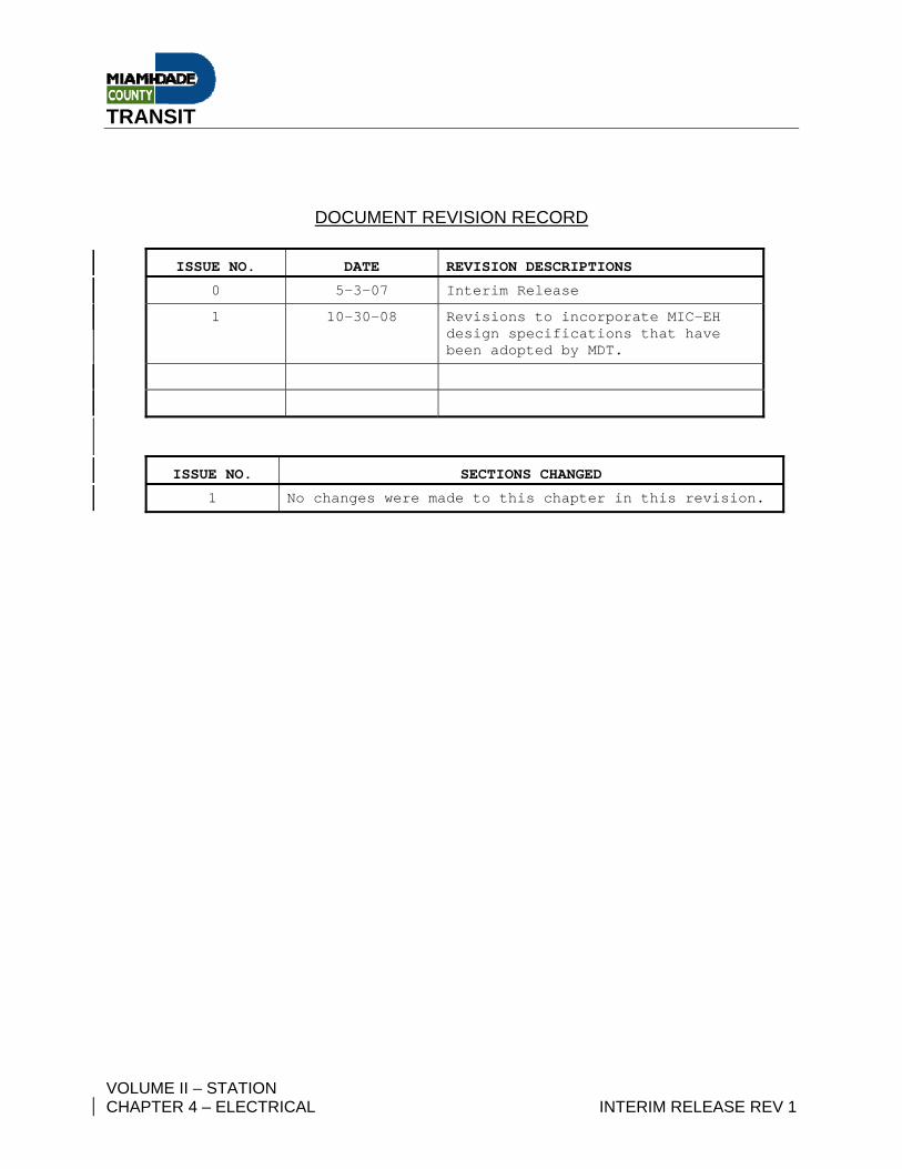
DOCUMENT REVISION RECORD
ISSUE NO. DATE REVISION DESCRIPTIONS
0 5-3-07 Interim Release
1 10-30-08 Revisions to incorporate MIC-EH design specifications that have been adopted by MDT.
ISSUE NO. SECTIONS CHANGED
1 No changes were made to this chapter in this revision.
TRANSIT
VOLUME II – STATION CHAPTER 4 – ELECTRICAL INTERIM RELEASE REV 1
– Intentionally Left Blank –
TRANSIT
VOLUME II – STATION i CHAPTER 4 – ELECTRICAL INTERIM RELEASE REV 1
VOLUME II - STATION
CHAPTER 4 – ELECTRICAL DESIGN CRITERIA
REVISION 1 Table of Contents Page No.
4.01 GENERAL............................................................................................................ 1 4.01.1 PURPOSE ..................................................................................................... 1 4.01.2 BASIC GOALS.............................................................................................. 1 4.01.3 SCOPE .......................................................................................................... 2 4.01.4 OTHER RELATED DESIGN CRITERIA........................................................ 2 4.01.5 INTERFACE DEFINITION AND CONTROL.................................................. 3 4.01.6 CODES, STANDARDS AND REGULATIONS.............................................. 4 4.01.7 PROCUREMENT AND INSTALLATION (RESERVED)................................ 6
4.02 ELECTRICAL SYSTEMS..................................................................................... 7 4.02.1 SCOPE .......................................................................................................... 7 4.02.2 POWER SUPPLY.......................................................................................... 8
4.02.2.1 Primary Power........................................................................................ 8 4.02.2.2 Concrete Encased Service Duct Banks ................................................. 9
4.02.3 INCOMING TELEPHONE SERVICE AND PUBLIC TELEPHONES........... 10 4.02.4 GENERAL ELECTRICAL CHARACTERISTICS......................................... 10 4.02.5 DEMAND FACTORS................................................................................... 12 4.02.6 PANELBOARDS ......................................................................................... 13
4.02.6.1 General ................................................................................................ 13 4.02.6.2 Panel board Designations .................................................................... 13
4.02.7 MOTORS ..................................................................................................... 14 TABLE 1 – MOTOR WIRING AND LOAD DATA - RESERVED .................................. 14
4.02.8 MOTOR CONTROLS .................................................................................. 15 4.02.8.1 General ................................................................................................ 15
4.02.9 EMERGENCY AND STANDBY SYSTEMS................................................. 16 4.02.9.1 Automatic Transfer Switches (ATS) ..................................................... 16 4.02.9.2 Uninterruptible Power Supply and Generator....................................... 16 4.02.9.3 Emergency Power................................................................................ 16 4.02.9.4 Standby Power..................................................................................... 17 4.02.9.5 Uninterruptible Power Supplies (UPS) ................................................. 17 4.02.9.6 UPS Management................................................................................ 17 4.02.9.8 Generator size...................................................................................... 18 4.02.9.9 Generator Startup ................................................................................ 18 4.02.9.10 Generator Operation Time ................................................................... 18 4.02.9.11 Restoration of Primary Power .............................................................. 19
4.02.10 WIRING METHODS..................................................................................... 19 4.02.11 MATERIAL .................................................................................................. 19 4.02.12 VOLTAGE DROP ........................................................................................ 24 4.02.13 HEATING, VENTILATION AND AIR CONDITIONING AND CONTROLS.. 24
TRANSIT
VOLUME II – STATION ii CHAPTER 4 – ELECTRICAL INTERIM RELEASE REV 1
4.02.14 ELEVATORS............................................................................................... 25 4.02.15 ESCALATORS ............................................................................................ 25 4.02.16 PUMP AND COMPRESSOR STATIONS.................................................... 25 4.02.17 TRAIN CONTROL AND COMMUNICATIONS ROOM................................ 25
4.02.17.1 Train Control ........................................................................................ 25 4.02.17.2 Communications .................................................................................. 26
4.02.18 CHANGE DISPENSING AND FARE COLLECTION EQUIPMENT ............ 26 4.02.19 TRACTION POWER SUBSTATION............................................................ 27 4.02.20 GAP TIE STATION...................................................................................... 27 4.02.21 BLUE LIGHT EMERGENCY TRIP STATIONS ........................................... 28 4.02.22 FIRE PUMPS............................................................................................... 28 4.02.23 PARKING STRUCTURES........................................................................... 28
4.03 FACILITIES SUPERVISORY CONTROL~ STATUS AND ALARM REQUIREMENTS............................................................................................... 31
4.03.1 SCOPE ........................................................................................................ 31 TABLE 4-2 – FACILITIES SUPERVISORY CONTROL, STATUS AND ALARM
REQUIREMENTS (EXAMPLE) .......................................................................... 35 4.04 GROUNDING AND LIGHTNING PROTECTION (Reserved) ............................ 65
4.04.1 SCOPE (Reserved)..................................................................................... 65 4.04.2 OBJECTIVE (Reserved) ............................................................................. 65 4.04.3 ABNORMAL CONDITIONS (Reserved) ..................................................... 65 4.04.4 GROUNDING ELECTRODE SYSTEM (Reserved) .................................... 65 4.04.5 TRACTION POWER GROUNDING (Reserved) ......................................... 65 4.04.6 SECONDARY POWER DISTRIBUTION SYSTEM GROUNDING
(Reserved) .................................................................................................. 65 4.04.7 GROUNDING NETWORKS (Reserved) ..................................................... 65 4.04.8 LIGHTNING PROTECTION (Reserved) ..................................................... 65
4.05 CORROSION CONTROL (Reserved) ............................................................... 67 4.05.1 SCOPE (Reserved)..................................................................................... 67 4.05.2 CONTROL OF ATMOSPHERIC CORROSION (Reserved) ....................... 67 4.05.3 STRAY CURRENT CORROSION CONTROL (Reserved) ......................... 67 4.05.4 CATHODIC PROTECTION (Reserved) ...................................................... 67 4.05.5 TEST STATIONS (Reserved) ..................................................................... 67 4.05.6 CORROSION CONTROL OF MECHANICAL EQUIPMENT (Reserved) ... 67 4.05.7 MISCELLANEOUS ITEMS (Reserved) ...................................................... 67
4.06 SYSTEMS-FACILITIES INTERFACE RACEWAY (Reserved) ......................... 69 4.06.1 SCOPE (Reserved)..................................................................................... 69 4.06.2 PHYSICAL RELATIONSHIP (Reserved).................................................... 69 4.06.3 PHYSICAL INSTALLATION (Reserved) .................................................... 69 4.06.4 MATERIALS OF CONSTRUCTION (Reserved)......................................... 69 4.06.5 RACEWAY IDENTIFICATION METHODS (Reserved) .............................. 69
4.07 LIGHTING DESIGN CRITERIA.......................................................................... 71 4.07.1 INTRODUCTION ......................................................................................... 71
TRANSIT
VOLUME II – STATION iii CHAPTER 4 – ELECTRICAL INTERIM RELEASE REV 1
4.07.2 DESIGN OBJECTIVES ............................................................................... 72 4.07.3 CALCULATIONS......................................................................................... 74 4.07.4 SITE AREAS ............................................................................................... 75
4.07.4.1 General ................................................................................................ 75 4.07.5 PASSENGER STATIONS ........................................................................... 76 4.07.6 TRACTION POWER SUBSTATIONS AND GAP TIE STATIONS .............. 78 4.07.7 ANCILLARY SPACES ................................................................................ 78 4.07.8 EMERGENCY LIGHTING............................................................................ 79 4.07.9 CONTROL OF LIGHTING SYSTEM ........................................................... 79
TABLE 4-3 – SITE AREA ILLUMINATION LEVELS.................................................... 81 TABLE 4-4 – PASSENGER STATION ILLUMINATION LEVELS ............................... 82 TABLE 4-5 - TRACTION POWER SUBSTATION & GAP TIE STATION
ILLUMINATION LEVELS................................................................................... 83 TABLE 4-6 – ANCILLARY SPACES ILLUMINATION LEVELS .................................. 84 TABLE 4-7 - EMERGENCY LIGHTING ILLUMINATION LEVELS .............................. 85 APPENDIX A (Reserved)............................................................................................. 86

TRANSIT
VOLUME II – STATION iv CHAPTER 4 – ELECTRICAL INTERIM RELEASE REV 1
– Intentionally Left Blank –
TRANSIT
VOLUME II – STATION 1 CHAPTER 4 – ELECTRICAL INTERIM RELEASE REV 1
4.01 GENERAL 4.01.1 PURPOSE
These criteria apply to the design of electric power, control, lighting and
supervisory subsystems for the Stations within the Metrorail Line Extension.
Within this document, the term “Stations” refer to Metrorail facilities, to
include; passenger stations, train control and communications rooms, traction
power stations, gap tie stations, parking structures or parking lots, guard
stations and other related structures unless otherwise noted. The Electrical
criteria applicable to the guideway structure are covered in Volume III -
Guideway, Chapter 4, Electrical Design Criteria, which should be used in
close conjunction with this design criteria. Also supplementing these criteria
are the Electrical Standard, Directive Drawings and other related design
criteria
4.01.2 BASIC GOALS 4.01.2.1 The design shall:
A. Provide for safe, economical, reliable and continuous operation of the
entire Metrorail system.
B. Promote uniformity and standardization in design and equipment.
C. Facilitate installation and maintenance of the equipment.
D. Provide reasonable spare capacity for future use, specifically spare
electrical service capacity, panel spaces and spare conduits.
TRANSIT
VOLUME II – STATION 2 CHAPTER 4 – ELECTRICAL INTERIM RELEASE REV 1
4.01.3 SCOPE The following shall be included in the scope of the Station’s electrical system
design:
A. The electrical power requirements for the Metrorail stations and related
facilities. The Station’s electrical design shall provide the necessary
electrical power, panels, raceways, conduits, conductors and cables to
support all Metrorail systems related to the Station.
B. A raceway system is required to provide pathways for all cables and
conductors between the station, facilities and equipment to include
wayside equipment. Raceway systems and interfaces from the stations
to the guideway structure are also covered in Volume III - Guideway,
Chapter 4, Electrical Design Criteria.
C. Supervisory monitoring of the facilities and equipment.
D. Lighting requirements.
4.01.4 OTHER RELATED DESIGN CRITERIA In addition to this Stations design criteria, other criteria, listed below, have
requirements related to the Station’s electrical design
4.01.4.1 The station’s electrical design must accommodate the Station’s Fire Alarm
System, CCTV Security System, Public Address System, Variable Message
Signs, and an Access Control System. Refer to:
Volume I – Systemwide
Chapter 7 – System Safety
Chapter 8 – System Security
TRANSIT
VOLUME II – STATION 3 CHAPTER 4 – ELECTRICAL INTERIM RELEASE REV 1
Chapter 9 - Fire/Life Safety
4.01.4.2 Grounding and lightning protection is required for all aerial and at grade fixed
facilities and equipment at the Stations to include rail, fences, and wayside
equipment. To avoid duplication, these criteria are now covered in Volume III
– Guideway, Chapter 4, Electrical Design Criteria
4.01.4.3 Corrosion control requirements exist for the Stations and related facilities for
monitoring, controlling and minimizing stray currents. To avoid duplication,
these criteria are now covered in Volume III – Guideway, Chapter 4, Electrical
Design Criteria.
4.01.4.4 Supervisory monitoring of the facilities and equipment is required. The
Station’s equipment alarms and control signal lines are required to interface
to the Metrorail Communications Network (MCN). Only the alarms and
control signals related to the Station’s electrical system are identified in this
criteria. Other Metrorail Systems within the Stations and their interfaces are
covered in separate criteria. Refer to:
Volume VII – Systemwide Equipment,
Chapter 1 – Traction Power Equipment
Chapter 3 – Traction Power Installation
Chapter 4 – Fare Collection
Chapter 6 – Train Control
Chapter 7 – Communications
4.01.5 INTERFACE DEFINITION AND CONTROL The Station's electrical subsystem interfaces with a number of other
subsystems and incorporates many interfaces between subsystems. In every
case of subsystem to subsystem interface (for example, Traction Power
TRANSIT
VOLUME II – STATION 4 CHAPTER 4 – ELECTRICAL INTERIM RELEASE REV 1
Substation / Passenger Station Interface) the interface will be defined by the
Designer, and approved by MDT. Changes shall only be made upon approval
by MDT. Section 4.06, Systems/Facilities Interface Raceway defines these
interfaces to a great extent. Electrical subsystem interfaces are defined within
these criteria and other related criteria and may change during the design
process by MDT directive.
Commentary: Since the phase I electrical design was performed by more than
one group, the design criteria attempted to define specific interface raceways
between subsystems in detail. Since it is anticipated the new extension
designs will be the responsibility of a single designer, and the interfaces and
conduits may vary from phase I, the raceway requirements provided within
this criteria should be used only as a guideline.
4.01.6 CODES, STANDARDS AND REGULATIONS 4.01.6.1 Unless otherwise indicated elsewhere, the Station’s electrical system design
shall conform to the latest edition of the following codes, standards and
regulations:
• National Electrical Code (NEC)
• National Electric Safety Code (NESC)
• Miami-Dade County, City of Miami, Coral Gables, Hialeah and
other Authorities Having Jurisdiction (AHD)
• American National Standards Institute (ANSI)
• National Electric Manufacturers Association (NEMA)
• Institute of Electrical and Electronic Engineers (IEEE)
• Insulated Power Cable Engineers Association (IPCEA)
• The Occupational Safety and Health Act (OSHA)
TRANSIT
VOLUME II – STATION 5 CHAPTER 4 – ELECTRICAL INTERIM RELEASE REV 1
• Florida Building Code (FBC)
• Lightning Protection Code (NFPA No. 780)
• Local Protective Signaling Systems (NFPA No. 72A)
• Proprietary Signaling Systems (NFPA No. 72D)
• Automatic Fire Detectors (NFPA No. 72E)
• Life Safety Code (NFPA 101)
• American Society for Testing and Materials (ASTM)
• Certified Ballast Manufacturers Association (CBM)
• Underwriters' Laboratories, Inc. (UL)
• Illuminating Engineering Society (IES)
• Florida Fire Prevention Code
• American with Disabilities Act (ADA)
The current version of these documents, and applicable codes, standards and
regulations shall apply, and unless otherwise directed, all addenda, interim
supplements, revisions and ordinances by the respective code body shall also
apply. Where conflicts exist between these documents, the more stringent
requirement shall take precedence, unless otherwise directed by MDT.
Electrical design work shall be performed in accordance with the rules and
regulations of the State of Florida, Department of Business Regulation, for
Professional Engineers (PE).
4.01.6.2 Where the requirements of more than one code or standard are applicable or
are in conflict, the Designer shall bring it to the attention of MDT in a timely
manner with a recommendation for resolution by MDT.
TRANSIT
VOLUME II – STATION 6 CHAPTER 4 – ELECTRICAL INTERIM RELEASE REV 1
4.01.7 PROCUREMENT AND INSTALLATION (RESERVED)
TRANSIT
VOLUME II – STATION 7 CHAPTER 4 – ELECTRICAL INTERIM RELEASE REV 1
4.02 ELECTRICAL SYSTEMS 4.02.1 SCOPE
This section defines the general design requirements for the electrical power,
control and communications of the facilities elements for the Metrorail Line
Extension. These elements include:
o Plumbing and irrigation
o Heating, ventilation and air conditioning
o Escalators and Elevators
o Change dispensing and fare collection equipment power supply
o Backup and Emergency power
o Facilites Lighting
o Utility receptacles & Inspection lighting
o Clocks
o Illuminated fixed signing
o Variable Message Signs
o Parking lot control gates
o Train control equipment power supply
o Communication equipment power supply
o Traction Power Substation auxiliaries
o Gap Tie Station auxiliaries
o Blue Light Station with Emergency Trip Station (ETS)
o CCTV System
o Public Address (PA) System
o Fire Alarm System
o Access Control and Intrusion Alarms
TRANSIT
VOLUME II – STATION 8 CHAPTER 4 – ELECTRICAL INTERIM RELEASE REV 1
4.02.2 POWER SUPPLY 4.02.2.1 Primary Power
A. Primary power at 13.2 kiloVolts (kV) shall be supplied to the Passenger
Station Electrical Equipment Room by the electrical utility provider by
means of two feeders. These feeder circuits will be terminated at the line
side of each three-pole, two-position (open-close) load break air
interrupter switch of each indoor type unit substation.
B. Each primary feeder shall be sized for a minimum of 150 percent of the
self-cooled rating of the transformer and to withstand the maximum
available short circuit current.
C. Each unit substation equipment shall consist of one metal enclosed 15
kV two-position load break air interrupter switch; one three-phase dry
type ventilated transformer, 13.2 kV-480Y/277 Volts; one 480 Volt main
power circuit breaker and necessary molded case feeder circuit
breakers. One of the substations shall have one 480 Volt tie power
circuit breaker. Each transformer shall be sized to handle the total
demand load of the Passenger Station and other auxiliaries without the
need of fan cooling. Transformers shall have provisions for fan cooling, if
needed in the future. The main circuit breakers shall be provided with
solid state long-and-short time trip devices and ground fault protection.
All feeder breakers shall be provided with long time and instantaneous
trips. Normally, both main breakers shall remain closed and the tie
breaker shall remain open. Main circuit breakers and the tie circuit
breaker shall be provided with an automatic throw over control which
operates in the following manner:
TRANSIT
VOLUME II – STATION 9 CHAPTER 4 – ELECTRICAL INTERIM RELEASE REV 1
In the event of loss of power on any of the incoming feeders, or loss of a
transformer, an under voltage relay shall sense the loss of voltage and
trip the respective main breaker after a time delay of five seconds. If the
normal voltage is restored during the time delay period, the main breaker
shall remain closed. Once a main breaker opens, the tie breaker shall
close after a time delay of five seconds thus restoring power to the dead
switchboard. Upon restoration of power to the failed feeder or after the
transformer has been properly refurbished, the breakers shall be
restored to their normal position manually. The above transfer operation
shall take place only for tripping of the main breaker due to under
voltage. For other tripping of the main breaker, such as short circuit or
ground fault, the tie breaker shall remain open.
For the extension design, the Designer shall investigate the suitability of
modern Intelligent Electronic Breakers with expanded control and
monitoring capabilities over the existing implementation and provide a
recommendation to MDT.
4.02.2.2 Concrete Encased Service Duct Banks
A. The Passenger Station incoming primary feeder duct bank shall consist
of a minimum of four each 4” diameter PVC conduits (two spares) and
two each 2” diameter PVC conduits (one 2” diameter conduit for 480V
feeder to Traction Power Substation and one 2” diameter spare conduit)
and shall extend from the passenger station Electrical Equipment Room
to the Traction Power Substation at a minimum of two feet below ground
level and identified. Duct bank concrete envelope and reinforcing shall
be as indicated on Electrical Standard Drawings.
TRANSIT
VOLUME II – STATION 10 CHAPTER 4 – ELECTRICAL INTERIM RELEASE REV 1
B. The Parking Structure service duct bank shall extend from the
passenger station Electrical Equipment Room to the Parking Structure
Main Electrical Closet. Duct bank configuration, number and size of PVC
conduits shall be determined taking into consideration both initial and
future level lighting loads; elevators and fire pump (if any), CCTV and
other systems. Refer to the other related design criteria for complete
parking structure electrical requirements.
4.02.3 INCOMING TELEPHONE SERVICE AND PUBLIC TELEPHONES 4.02.3.1 One 2” diameter PVC empty conduit shall be extended from the telephone
backboard in the passenger station Electrical Room to the station property
line and capped for telephone incoming service. Coordinate exact location of
stub out, hand holes and other requirements with the telephone service
provider selected by MDT; BellSouth or other.
Two 1” diameter PVC empty conduits shall be provided, one from each end of
the Fare Collection area, to the Telephone Backboard in the passenger
station Electrical Room for public telephones. Conduits in the Fare Collection
area shall be terminated in a flush outlet box four feet above finished floor in
the Public Telephone Booths.
ADA requirements shall be taken into consideration for public telephone
locations and access.
4.02.4 GENERAL ELECTRICAL CHARACTERISTICS Facilities distribution voltage shall be nominal 480Y/277 Volts, three phase,
four wire, 60 hertz. Voltage other than the distribution voltage shall be
obtained with dry type transformers. Utilization voltages for electrical devices

TRANSIT
VOLUME II – STATION 11 CHAPTER 4 – ELECTRICAL INTERIM RELEASE REV 1
and equipment requiring ac power shall conform to the following
characteristics:
• Fluorescent lighting 277 Volts, single phase
• Incandescent lighting 120 Volts, single phase
• High intensity discharge lighting 277 Volts, single phase
• Convenience receptacles 120 Volts, single phase
• Inspection lighting receptacles (in box structures) 120 Volts, single phase
• Motors 1/2 HP and above (Motor rating 460 v, three phase) 480 Volts, three phase
• Motors under 1/2 HP 120 Volts, single phase or 208 Volts, single phase
• Starter control power As required
• Hot water tank heaters & space heaters 120 Volts, single phase up to 1,000 watts 208 or 480 Volts, single above 1,000 watts or three phase
• Train Control and 120 Volts, single phase Communications equipment and 208Y/120 Volts, three Phase (Derived system through Isolation transformer)
• Change Dispensing and Fare Collection equipment 120 Volts, single phase
• Feeder to Traction Power 480Y/277 Volts, three Substations phase, four wire
• Feeder to Gap Tie Stations 277 Volts, single phase, two wire
• Emergency power As Required per NFPA and other applicable codes
• Special receptacles As Required
• Electric clocks As required
TRANSIT
VOLUME II – STATION 12 CHAPTER 4 – ELECTRICAL INTERIM RELEASE REV 1
• Dry type transformers 480 Volts delta to 208Y/120 Volts, three phase, four wire
• Incremental air conditioners 120 or 208 Volts, single phase
4.02.5 DEMAND FACTORS
The following demand factors shall be used for sizing unit substation
transformers:
Service Demand Factor • Lighting and signs per N.E.C.
• Emergency lighting per N.E.C.
• Fare collection equipment per N.E.C.
• Elevators per N.E.C.
• Escalators per N.E.C.
• Ventilation equipment per N.E.C.
• Air conditioning equipment per N.E.C.
• Drainage pumps and ejectors per N.E.C.
• Traction Power Substation per N.E.C. auxiliaries
• Gap Tie Station auxiliaries per N.E.C.
• Train control equipment per N.E.C.
• Communications equipment per N.E.C.
• Convenience receptacle per N.E.C.
One hundred percent demand factor shall be used for sizing feeder circuit
breakers and their respective feeders.
TRANSIT
VOLUME II – STATION 13 CHAPTER 4 – ELECTRICAL INTERIM RELEASE REV 1
4.02.6 PANELBOARDS 4.02.6.1 General
A. Panel boards shall be located in Electrical Equipment Rooms, Electrical
Rooms, Electrical Closets or suitable ancillary rooms located near the
loads to be served. All branch circuit homeruns shall be shown and
identified on the floor plans with the panel board designation and circuit
number for the individual circuit. Conduit and Feeder Schedules shall be
used to list all empty conduits and all feeders. Panel boards shall be
Equipped with a minimum of 20 percent spare breakers.
B. Ampacity and protection of panel board feeders shall be adequate for
the size of the panel boards based on the demand load, plus estimated
future load.
4.02.6.2 Panel Board Designations
Panel boards shall be designated depending on their function and service
Voltage as follows:
480Y/277 Volts Designation
Lighting panel L1, L2, L3, etc.
Distribution panel DI,D2,D3, etc.
Power panel P1,P2,P3, etc.
Motor control center MCCI,MCC2,MCC3, etc.
Motor starter panel MSPI,MSP2,MSP3, etc.
Emergency lighting panel EL1,EL2,EL3, etc.
Emergency power panel EP1, EP2, EP3, etc.
Emergency distribution panel ED1, ED2, ED3, etc.
TRANSIT
VOLUME II – STATION 14 CHAPTER 4 – ELECTRICAL INTERIM RELEASE REV 1
Standby lighting panel SL1,SL2,SL3, etc.
Standby power panel SP1, SP2, SP3, etc
Standby distribution panel SD1, SD2, SD3, etc.
208Y/120 Volts Designation
Lighting, receptacles and LL1, LL2, LL3, etc. miscellaneous power
Distribution panel DD1, DD2, DD3, etc.
Emergency lighting panel ELL1, ELL2, ELL3, etc.
Emergency power panel EPP1, EPP2, EPP3, etc.
Standby lighting panel SLL1,SLL2,SLL3, etc.
Standby power panel SPP1, SPP2, SPP3, etc
4.02.7 MOTORS
Integral horsepower motors for driven equipment shall be totally enclosed fan
cooled squirrel cage induction motors. They shall be High Efficient NEMA
Design B unless the application requires other torque-speed characteristics.
Fractional horsepower motors shall be totally enclosed fan cooled or non-
ventilated except where applications or environmental conditions dictate
otherwise.
TABLE 1 – MOTOR WIRING AND LOAD DATA - RESERVED
TRANSIT
VOLUME II – STATION 15 CHAPTER 4 – ELECTRICAL INTERIM RELEASE REV 1
4.02.8 MOTOR CONTROLS 4.02.8.1 General
A. Circuit breaker combination starters in motor control center type
construction shall be used for the 480 Volt motors. Motor control
centers shall be equipped with a main circuit breaker as part of the
equipment. Main busses shall be adequately braced for the available
short circuit. Motor control centers shall be NEMA Class II, Type B
wiring. However, individually mounted circuit breaker combination
starters may be used where practicable.
B. All starters shall be magnetic, full voltage start, single speed, non-
reversing type or reversing type except when the driven equipment
characteristics require other types. Each three phase starter shall be
equipped with 120 Volt control power transformer and three thermal
overload relays, and auxiliary contacts for remote monitoring. Each
single phase starter shall be equipped with 120 Volt coil and two thermal
overload relays.
C. Control stations having lockout type stop button and a start button or
hand-off-auto switch may be provided near each motor.
D. Enclosures for motor control centers, motor starters and control devices
shall be NEMA type 12 except where environmental conditions dictate
otherwise. Wiring for motors, size of starter and circuit breaker ratings
shall be per N.E.C.
TRANSIT
VOLUME II – STATION 16 CHAPTER 4 – ELECTRICAL INTERIM RELEASE REV 1
4.02.9 EMERGENCY AND STANDBY SYSTEMS 4.02.9.1 Automatic Transfer Switches (ATS)
The primary power feeders, one from each unit substation, shall be
connected to the line side of the necessary Automatic Transfer Switches
(ATS) installed at the station. The ATSs shall be a 4 wire units which also
switches the neutral.
4.02.9.2 Uninterruptible Power Supply and Generator
Backup power is required in the event of interruption of primary power- the
electrical power supplied by the utility. Backup power shall be supplied at the
station by a combination of a battery powered uninterruptible Power Supply
(UPS) and a LPG fueled generator.
The back power is intended to supply;
A. Emergency loads, and
B. Standby loads essential to station operations.
It is important to define these loads separately, since their specific power
requirements, durations, certifications and inspections vary.
4.02.9.3 Emergency Power
Emergency Power is defined as power needed to supply the equipment in
order to comply with life/safety requirements as determined by applicable
codes, the AHJ and MDT.
Emergency power shall be provided for operation of the following equipment:
A. Emergency lighting
B. Exit signs
C. Emergency audio-visual announcements (Horns, PA and VMS signs)
TRANSIT
VOLUME II – STATION 17 CHAPTER 4 – ELECTRICAL INTERIM RELEASE REV 1
D. Fire & Life Safety related loads
The Designer shall investigate other equipment which may require
emergency power in order to properly operate in an emergency situation,
such as;
A. Access Control equipment -gates and door locks
B. Fare collection equipment for emergency egress
4.02.9.4 Standby Power
Standby backup power shall be provided for operation of the following:
A. Select Non- Emergency station lighting
B. Access Control equipment
C. Train control equipment
D. Fare collection equipment
E. Communications equipment circuits (Refer to Vol VII, Chapter 7-
Communications Design Criteria).
4.02.9.5 Uninterruptible Power Supplies (UPS)
Uninterruptible Power Supplies (UPS) shall consist of pre-engineered
"packaged" stackable “smart” units. These units shall contain all components
necessary for the operation of the loads, to include; Batteries, transfer
system, charger, inverter, test switch, load centers, indicator lights and
meters. The UPS shall be “online” at all times, thereby filtering the power to
the loads and preventing an interruption of power upon a primary power
failure.
4.02.9.6 UPS Management
The UPS shall be provided with SNMP compatible management program with
an Ethernet interface for control and monitoring. UPS management interface
TRANSIT
VOLUME II – STATION 18 CHAPTER 4 – ELECTRICAL INTERIM RELEASE REV 1
will connect to the MDT communications network as defined in Volume 7,
Chapter 7 - Communications System Criteria.
4.02.9.7 The battery systems shall have sufficient capacity to:
A. Supply the emergency load continuously for 90 minutes, unless
otherwise dictated by other codes, the AHJ or as directed by the MDT
B. Supply the standby loads for 90 minutes, unless otherwise directed by
MDT
In the event of the station’s generator failure to start, the 90 minute battery
capacity will assure code compliance and an orderly shutdown of station
operations.
4.02.9.8 Generator size
The Generator when in operation shall be properly sized to provide power to;
A. The emergency loads,
B. The standby loads, and
C. To restore and maintain the charge on the UPS batteries.
4.02.9.9 Generator Startup
The generator shall be programmed to start within five minutes of a primary
power failure. The generator ATS shall switch the generator online, replacing
the utility as the primary source of power to the loads listed in 4.02.9.7.
4.02.9.10 Generator Operation Time
The generator’s fuel tank shall be sized to provide up to 72 hours of operation
while supplying power to the loads listed in 4.02.9.7.
TRANSIT
VOLUME II – STATION 19 CHAPTER 4 – ELECTRICAL INTERIM RELEASE REV 1
4.02.9.11 Restoration of Primary Power
Upon restoration of primary power from the utility, the load shall be
automatically transferred from the generator to the primary source. The UPS
will remain online, thereby providing uninterrupted filtered power to the loads.
4.02.10 WIRING METHODS Wiring within facility areas shall be in rigid metallic or non-metallic conduits as
described in Section 4.02.11. Cable trays may be used in specific areas
when approved by MDT. Expansion fittings shall be provided where conduits
pass through expansion joints.
Conduits shall be concealed within the station passenger areas where
possible.
Pull and junction boxes shall be accessible or preferably readily accessible as
defined by NEC.
4.02.11 MATERIAL 4.02.11.1 Materials used shall be listed by UL or other NRTL and conform to the
following:
A. Conduit
1) Minimum size of conduit shall be 3/4 inch for exposed work and
one inch conduits embedded within a column and for all embedded
applications in floor slabs. 1/2 inch conduits are acceptable for
small diameter low voltage communications and CCTV cables.
Conduit fill ratios shall not exceed NEC standards.
TRANSIT
VOLUME II – STATION 20 CHAPTER 4 – ELECTRICAL INTERIM RELEASE REV 1
2) Galvanized rigid steel conduit shall be used for exposed and
embedded work and concealed work in ceiling spaces or behind
walls.
3) Rigid non-metallic conduit shall be used for underground or under
floor applications, either direct burial or concrete encasement. An
example of the application is for enclosing primary feeder
conductors which run from the Traction Power Substations to
Passenger Station Electrical Equipment Rooms. Rigid non-metallic
conduit shall not be used for the support of lighting fixtures. A
continuous green bonding wire shall be provided in all non-metallic
conduit runs.
4) Flexible metal conduit (minimum 18 inch length) shall be used for:
a) Recessed lighting fixtures
b) Transformers
c) Vibrating electrical equipment in dry locations
d) Other electrical equipment in dry locations for maintenance
convenience.
5) Liquid-tight flexible metal conduit (minimum 18 inch length) shall be
used for:
a) All motors
b) Vibrating electrical equipment in wet locations
c) Other electrical equipment in wet locations for maintenance
convenience.
6) Conduit fittings shall be of materials similar to the adjoining conduit.
TRANSIT
VOLUME II – STATION 21 CHAPTER 4 – ELECTRICAL INTERIM RELEASE REV 1
B. Cable Trays (within Passenger Stations) shall be non-metallic ladder
type. Power cables and control cables shall be in separate channels.
C. Under floor Ducts: Separate, non-metallic under floor ducts shall be used
to facilitate the separate routing of power and control cables from the
Change Dispensing and Fare Collection equipment to the Change
Dispensing and Fare Collection equipment panel board in the Electrical
Room and the Station Attendant's Booth, respectively.
D. Conductors:
1) All conductor material shall be copper. Use of aluminum
conductors must be specifically approved by MDT for each
application.
2) Conductors shall be properly sized for ampacity and voltage
drop per NEC. In general, minimum conductor size shall be
No. 16 AWG for fixture wire, No. 14 AWG for control and No.
12 AWG for lighting or power branch circuits.
3) Conductors for 15 kV application shall have cross-linked
polyethylene insulation, shielded, with overall neoprene jacket.
4) Conductor insulation for system voltages up to 480 Volts shall
be 600 Volt class, THHN or XHHW. (90°C insulation)
5) Fixture wire shall be type SF-2 or AF (for 300 Volt indoor use
only).
TRANSIT
VOLUME II – STATION 22 CHAPTER 4 – ELECTRICAL INTERIM RELEASE REV 1
6) For cable tray application, multi-conductor cables with flexible
galvanized steel armor (or other shielding when so required)
and neoprene jacket shall be utilized. Proper grounding fittings
shall be applied at the ends of all flexible armored cables at
terminations, boxes or cabinets to assure continuity of
grounding conductor. All metal surfaces shall be bonded
together. Where necessary, additional bonds or ground
connections shall be provided.
7) All feeders shall be sized for future growth of the system.
Short wiring interconnections between switches or panels shall
be in conduit. Cable splices shall be avoided; however, where
more than one length is required, splices shall be made in
properly sized accessible junction boxes.
E. Wiring Devices
1) Receptacles: Convenience duplex receptacles shall not be on
lighting circuits. All receptacles in public areas shall be installed in a
weatherproof, lockable type box and shall be protected by a ground
fault (GFI) type circuit receptacle. Convenience receptacles shall
be sized for 20 Ampere service. Not more than six receptacles
shall be placed on each circuit.
Convenience duplex receptacles shall be located as follows:
a) Public areas of station structure: These shall be spaced so
that not more than 50 feet of cord will be required to reach any
point from the receptacles. These receptacles shall be located
flush in the walls or in the floors as required. Special attention
TRANSIT
VOLUME II – STATION 23 CHAPTER 4 – ELECTRICAL INTERIM RELEASE REV 1
shall be given to floor mounted receptacles such that no
tripping hazard is presented.
b) Ancillary Spaces: There shall be a minimum of one surface
mounted duplex receptacle for each wall or 30 feet of wall
inside the ancillary spaces. More shall be provided where
indicated by operational requirements.
c) Maintenance Outlets in Passenger Station: One convenience
duplex receptacle shall be provided at every hose bib location
within the passenger station public areas. A safe separation
shall be provided between hose bib and receptacle.
d) Receptacles for guideway box structure inspections;
receptacles shall be installed within each guideway structure
at each inspection entrance to provide electrical power for
portable lighting for inspection purposes. The electrical power
shall be supplied by the nearest MDT facility.
See Vol. III Guideway, Chapter 4 Electrical.
2) Switches: Surface mounted wall switches shall be installed inside
each room of the ancillary spaces to control the lighting. Switches
shall be rated 20 amps, 120-277 Volt ac.
F. Disconnect Switches
Where required by the National Electrical Code, motor circuits shall have
integral disconnect switches, plug-in devices or separately mounted non-
fusible disconnect switches within sight of the motor. These devices and
switches shall be heavy duty safety types having a NEMA 12 enclosure
TRANSIT
VOLUME II – STATION 24 CHAPTER 4 – ELECTRICAL INTERIM RELEASE REV 1
for indoor dry locations and NEMA 4 for wet locations both indoor and
outdoor. All branch circuit disconnect switches shall be heavy duty type,
fused or un-fused, as the application requires.
G. Transformers
Transformers shall be dry type with standard full capacity taps on high
voltage winding. Transformers shall be three phase, having a 480 Volt
high voltage winding and a 208Y/120 Volt low voltage winding. They
shall be wall mounted for ratings up to 30 KVA.
4.02.12 VOLTAGE DROP Voltage drop calculations shall be prepared for all Branch circuits and
feeders. Calculations for motor circuits shall be based on the N.E.C. The
total voltage drop from the 480 Volt switchboard to the point of utilization shall
not exceed the following:
• Fluorescent lighting 5 percent
• Incandescent lighting (Indoor) 5 percent
• High intensity discharge lighting (indoor) 5 percent
• High intensity discharge lighting (Outdoor & Parking lots) 5 percent
• Receptacles 5 percent
• Motors 5 percent
• Incandescent lighting (Outdoor) 5 percent
4.02.13 HEATING, VENTILATION AND AIR CONDITIONING AND CONTROLS
Electrical power feeders and branch circuits shall be provided at each
passenger station for heating, ventilation and air conditioning and control
equipment described in Volume II, Chapter 5, Mechanical, of this
compendium.
TRANSIT
VOLUME II – STATION 25 CHAPTER 4 – ELECTRICAL INTERIM RELEASE REV 1
4.02.14 ELEVATORS The power supply to each elevator shall be sized per the equipment’s
requirement. A separate 120 Volt, 20 ampere circuit and 120 Volt, 20 ampere
emergency power circuit shall be provided for the hoistway and pit lighting
and receptacles and to return the elevator cab to the ground level and open
the doors respectively in the event of a power failure. The circuits shall be
terminated in separate fusible disconnect switches in the Elevator Machine
Room.
4.02.15 ESCALATORS The power supply for each escalator shall be sized per the equipment’s
requirement. The feeder shall be sized as per N.E.C. A separate 120 Volt,
20 ampere circuit shall be provided for each escalator for maintenance lights
and receptacles and terminated in a fusible disconnect switch in the Escalator
Pit.
4.02.16 PUMP AND COMPRESSOR STATIONS A 480Y/277 Volt, three phase, four wire feeders shall be run from the unit
substation or from a power panel board to the pump or compressor station.
4.02.17 TRAIN CONTROL AND COMMUNICATIONS ROOM 4.02.17.1 Train Control
One 208Y/120 Volt, three phase, four wire feeders shall be provided for a
demand load of 15 KVA at non-interlocking stations and 30 KVA at
interlocking stations. The designer shall obtain equipment loads and perform
calculations to confirm feeder sizes are adequate.
The Train Control equipment contains two redundant dc power supplies, each
with independent 120/208 Volt input feeds. To avoid a possible single point
TRANSIT
VOLUME II – STATION 26 CHAPTER 4 – ELECTRICAL INTERIM RELEASE REV 1
of failure, the two power supplies should be fed from separate power sources.
The Train Control primary dc power supply should be fed from the backup
power source. The input power to the second power supply should come
from a separate fused disconnect connected to the load side of the “A” feeder
in the Train Control & Communications room. The intent of this second direct
feed is to bypass the ATS, UPS and other associated circuits if those circuits
are powered down for maintenance.
4.02.17.2 Communications
A. One 208Y/120 Volt, three phase, four wire feeders shall be provided for
a demand load of 25 KVA at non-interlocking stations and 30 KVA at
interlocking stations.
B. One 120 Volt, single phase, two wire feeder shall be provided at all
stations for a demand load of 7.5 KVA.
Train Control and Communications feeders shall be supplied from the backup
power supply and terminated in an individually mounted circuit breaker
located in the Train Control and Communications Room. The designer shall
obtain equipment loads and perform calculations to confirm feeder sizes are
adequate.
4.02.18 CHANGE DISPENSING AND FARE COLLECTION EQUIPMENT 120 Volt, 60 Hz power shall be supplied to change dispensing and fare
collection equipment in accordance with the Electrical Directive Drawing from
a 208Y/120 Volt, three phases, four wire panel located in the Electrical Room.
Panel rating and number of poles shall be determined based on equipment
load requirements.
TRANSIT
VOLUME II – STATION 27 CHAPTER 4 – ELECTRICAL INTERIM RELEASE REV 1
The equipment circuits shall be supplied from the back-up power supply.
4.02.19 TRACTION POWER SUBSTATION The auxiliary lighting and power requirements of each Traction Power
Substation shall be supplied from the adjacent passenger station with one
480Y/277 Volt, three phases, four wire feeder fed from the load side of the
automatic transfer switch located in the passenger station Electrical
Equipment Room and one spare conduit.
Distribution equipment including distribution and lighting panels, transformer,
120 Volt convenience receptacles, and self-contained battery operated
emergency lights shall be provided inside the Traction Power Substation. In
addition to the above lighting and power requirements, the following loads
shall apply to the Traction Power Substation equipment:
208Y/120 Volt System Load Type of Load Breaker Type Quantity (Watts)
Heaters for ac Switchgear 1P-15A 11 5500 Heaters for dc Switchgear 1P-15A 9 4500 Outdoor Lighting for ac equipment 1P-20A 1 500 Spares 1P-20A 6 5400
4.02.20 GAP TIE STATION Each Gap Tie Station shall be supplied with one 277 Volt, single phase, two
wire auxiliary power feeder from one of the unit substations in the nearest
passenger station for power and lighting requirements as indicated on the
Electrical Directive and Standard Drawings. Distribution equipment including
distribution and lighting panels, transformer, 120 Volt convenience
receptacles and self-contained battery operated emergency lights shall be
TRANSIT
VOLUME II – STATION 28 CHAPTER 4 – ELECTRICAL INTERIM RELEASE REV 1
provided. In addition to lighting and power requirements, the following loads
shall apply to the Gap Tie Station equipment:
208Y/120 Volt System
Load Type of Load Breaker Type Quantity (Watts)
Heaters for dc switchgear 1P-15A 5 2500 Battery charger 1P-50 1 4320 Spares 1P-20A 4 3600 Communications (120V.1 phase) 1P-30A 1 2400
4.02.21 BLUE LIGHT EMERGENCY TRIP STATIONS Blue Light Stations with Traction Power Emergency Trip Stations (ETS) shall
be installed as specified in Volume VII, Chapter 1 Traction Power Equipment
and Chapter 3 Traction Power Installation Hardware.
Pull boxes which are accessible for maintenance without entering the
guideway shall be provided for the Blue Light ETS Stations conductors.
4.02.22 FIRE PUMPS Service to electrically operated fire pumps shall be per the requirements of
the NFPA 20.
4.02.23 PARKING STRUCTURES Separate feeders shall be provided for the lighting load, elevators and fire
pump. Electrical closets shall be provided to house the panel boards and
shall be located such that the largest conductor size used for lighting branch
wiring does not exceed #10. Electrical closets shall be located on the ground
level. Lighting panel boards shall be sized taking into consideration the future
levels. Emergency lighting shall be provided by means of pre-engineered

TRANSIT
VOLUME II – STATION 29 CHAPTER 4 – ELECTRICAL INTERIM RELEASE REV 1
"package" units fed from the Emergency Distribution panel located in the
Electrical Equipment Room.
Parking structures also contain Metrorail subsystems. Refer to the other
related design criteria listed in Section 4.01.4 for electrical requirements of the
equipment and facilities at the parking structure and lot.

TRANSIT
VOLUME II – STATION 30 CHAPTER 4 – ELECTRICAL INTERIM RELEASE REV 1
– Intentionally Left Blank –
TRANSIT
VOLUME II – STATION 31 CHAPTER 4 – ELECTRICAL INTERIM RELEASE REV 1
4.03 FACILITIES SUPERVISORY CONTROL~ STATUS AND ALARM
REQUIREMENTS 4.03.1 SCOPE
The station’s PLC based SCADA system provides the ability to send status
and alarms of the station’s equipment over the Metrorail Communications
Network (MCN) to the Central Control Facility (CCF) for monitoring and
logging purposes, and to receive commands from the CCF to control the
equipment.
This section defines the Supervisory Control, Status and Alarm requirements
for various Facility Electrical Subsystem equipment items, Facility Mechanical
Subsystem equipment items.
To insure a common understanding of the terms Supervisory Control, Status
and Alarm, indicated below is a brief description of each one of them:
1. Supervisory Control: The status monitoring and controlling of a specific
function of a component or subsystem of a system from either a local or
remote location, or both.
2. Status: The monitoring of a specific function of a component or
subsystem of a system from a local or remote location or both, which
does not require or include controlling the function. This is a
unidirectional method of indication.
3. Alarm: The monitoring of a specific component or subsystem function
from a local or remote location or both, which in addition to indicating
status, provides audible personnel alerting until acknowledged when the
TRANSIT
VOLUME II – STATION 32 CHAPTER 4 – ELECTRICAL INTERIM RELEASE REV 1
component or subsystem function is creating or is in an abnormal
condition. This is a unidirectional method of indication combined with a
personnel alerting capability.
Supervisory Control, Status and Alarm Functions can be either analog
(amplitude) or discrete (on/off) in content.
The Station’s equipment elements and subsystem’s Facilities supervisory
control, status and alarm wiring shall be interfaced to the SCADA system by
connecting to the Input/Output modules of the Station’s PLC.
The design of the SCADA system, the Metrorail Communications Network,
and the subsystem equipment is not within the scope of this section. These
are covered in other related design criteria, as listed in Section 4.01.4.
The Facilities Supervisory Control, Status and Alarm Requirements are
enumerated in an example table in the Communications criteria – Vol VII,
Chap 7. The Extension Designer shall use this table to prepare the Facilities
Contract documents. In order to standardize on the size and locations of the
equipment cabinets and the terminal assignments, the Designers are directed
to follow the existing stations drawings, and modify them only with prior
approval from MDT. For maintenance purposes, to the maximum extent
possible MDT requires a uniform and consistent design with the existing
facilities.
The Phase I Fire and Intrusion Alarm system and Intrusion system were
designed as one system. For the extensions, they are required to be
separate systems, compatible with the updated systems presently installed.
TRANSIT
VOLUME II – STATION 33 CHAPTER 4 – ELECTRICAL INTERIM RELEASE REV 1
The Fire System shall operate independently of other Metrorail systems.
Electrical power with associated raceways, conduits and other related items
shall be provided within the electrical design for the Fire System. The Station
Electrical design shall provide all necessary conduits and conductors for the
Fire System including detectors, alarms, strobes, panels as specified within
the Fire System design criteria, to include connections to the Metrorail
Communications Network (MCN).
Dedicated fibers shall be used for the Fire System communication. Specific
Fibers to be used and connection to the existing Fire System communications
ring shall be coordinated with MDT.
The Access Control System with intrusion alarms shall operate independently
of other systems. Electrical power with associated raceways, conduits and
other related items shall be provided for the Access Control and intrusion
System. Electrical design shall provide all necessary conduits and
conductors for the Access Control System to include connections to the MDT
Communications Network.
For other station equipment, the Designers are directed to follow the PLC
terminal assignments indicated on the existing installations and modify them
only with prior approval from MDT.
For Supervisory Control, Status and Alarm signals from subsystems so
equipped, the discrete signals will be transmitted to the PLC’s input modules
either by means of a momentary pulse of 0.25 Sec. minimum appearing on a
set of auxiliary dry contacts rated for a maximum of 125Vdc or 120Vac, 0.25
amp., or by an analog signal.

TRANSIT
VOLUME II – STATION 34 CHAPTER 4 – ELECTRICAL INTERIM RELEASE REV 1
Use of “Smart” subsystems which contain a network interface and
management system is encouraged.
Coordination with the Communications system designer is required.
NOTE: The following Table 2 – FACILITIES SUPERVISORY CONTROL, STATUS, AND ALARM REQUIREMENTS are based on the phase I implementation. The new equipment design may vary from the phase I design, but the basic requirements of this section remain the same.
TRANSIT
VOLUME II – STATION 35 CHAPTER 4 – ELECTRICAL INTERIM RELEASE REV 1
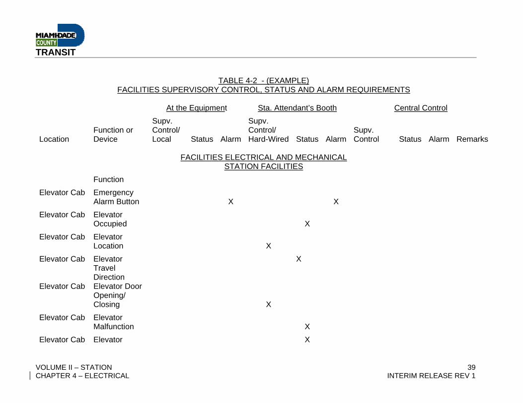
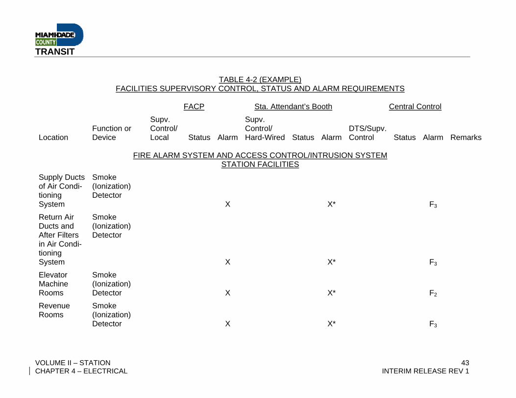
TABLE 4-2 – FACILITIES SUPERVISORY CONTROL, STATUS AND ALARM REQUIREMENTS (EXAMPLE)

TRANSIT
VOLUME II – STATION 36 CHAPTER 4 – ELECTRICAL INTERIM RELEASE REV 1
– Intentionally Left Blank –
TRANSIT
VOLUME II – STATION 37 CHAPTER 4 – ELECTRICAL INTERIM RELEASE REV 1
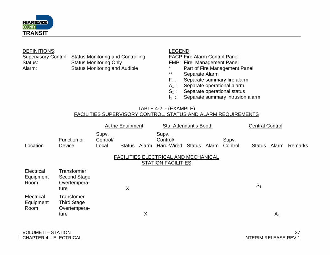
DEFINITIONS: LEGEND: Supervisory Control: Status Monitoring and Controlling FACP: Fire Alarm Control Panel Status: Status Monitoring Only FMP: Fire Management Panel Alarm: Status Monitoring and Audible * Part of Fire Management Panel ** Separate Alarm F1 : Separate summary fire alarm A1 : Separate operational alarm S1 : Separate operational status I1 : Separate summary intrusion alarm
TABLE 4-2 - (EXAMPLE) FACILITIES SUPERVISORY CONTROL, STATUS AND ALARM REQUIREMENTS
At the Equipment Sta. Attendant’s Booth Central Control
Location Function or Device
Supv. Control/ Local Status Alarm
Supv. Control/ Hard-Wired Status Alarm
Supv. Control Status Alarm Remarks
FACILITIES ELECTRICAL AND MECHANICAL
STATION FACILITIES Electrical Equipment Room
Transformer Second Stage Overtempera-ture
X
S1
Electrical Equipment Room
Transfomer Third Stage Overtempera-ture
X
A1
TRANSIT
VOLUME II – STATION 38 CHAPTER 4 – ELECTRICAL INTERIM RELEASE REV 1
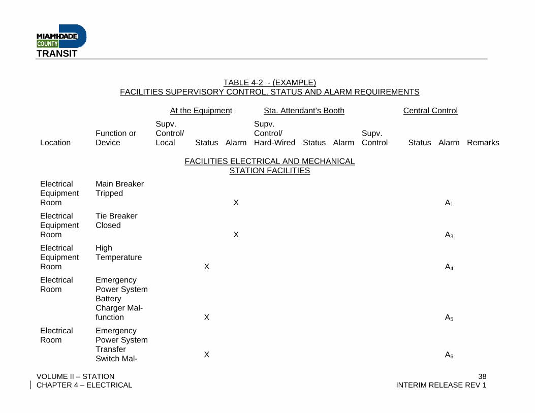
TABLE 4-2 - (EXAMPLE) FACILITIES SUPERVISORY CONTROL, STATUS AND ALARM REQUIREMENTS
At the Equipment Sta. Attendant’s Booth Central Control
Location Function or Device
Supv. Control/ Local Status Alarm
Supv. Control/ Hard-Wired Status Alarm
Supv. Control Status Alarm Remarks
FACILITIES ELECTRICAL AND MECHANICAL
STATION FACILITIES Electrical Equipment Room
Main Breaker Tripped
X
A1
Electrical Equipment Room
Tie Breaker Closed
X
A3
Electrical Equipment Room
High Temperature
X A4
Electrical Room
Emergency Power System Battery Charger Mal-function
X A5
Electrical Room
Emergency Power System Transfer Switch Mal-
X A6
TRANSIT
VOLUME II – STATION 39 CHAPTER 4 – ELECTRICAL INTERIM RELEASE REV 1
TABLE 4-2 - (EXAMPLE) FACILITIES SUPERVISORY CONTROL, STATUS AND ALARM REQUIREMENTS
At the Equipment Sta. Attendant’s Booth Central Control
Location Function or Device
Supv. Control/ Local Status Alarm
Supv. Control/ Hard-Wired Status Alarm
Supv. Control Status Alarm Remarks
FACILITIES ELECTRICAL AND MECHANICAL
STATION FACILITIES Function
Elevator Cab Emergency Alarm Button
X X
Elevator Cab Elevator Occupied
X
Elevator Cab Elevator Location
X
Elevator Cab Elevator Travel Direction
X
Elevator Cab Elevator Door Opening/ Closing
X
Elevator Cab Elevator Malfunction
X
Elevator Cab Elevator X
TRANSIT
VOLUME II – STATION 40 CHAPTER 4 – ELECTRICAL INTERIM RELEASE REV 1
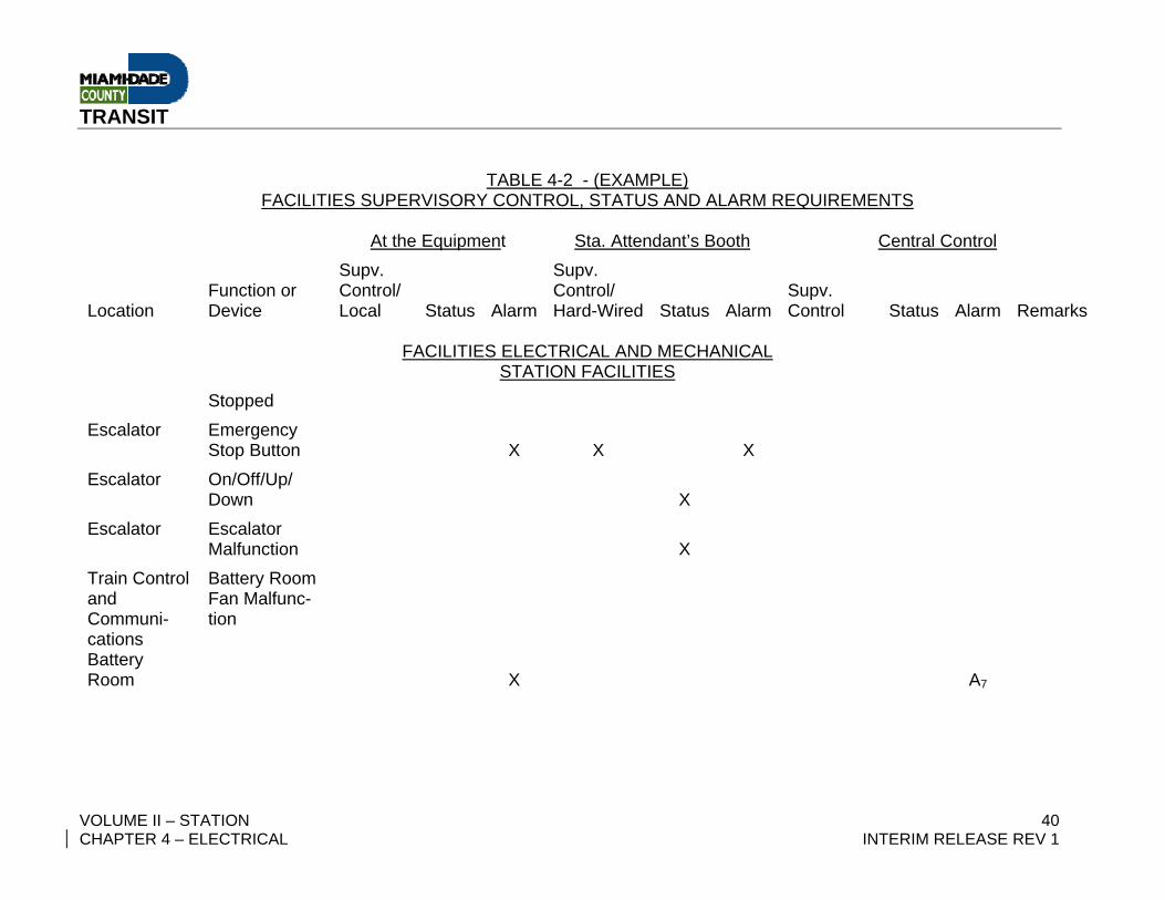
TABLE 4-2 - (EXAMPLE) FACILITIES SUPERVISORY CONTROL, STATUS AND ALARM REQUIREMENTS
At the Equipment Sta. Attendant’s Booth Central Control
Location Function or Device
Supv. Control/ Local Status Alarm
Supv. Control/ Hard-Wired Status Alarm
Supv. Control Status Alarm Remarks
FACILITIES ELECTRICAL AND MECHANICAL
STATION FACILITIES Stopped
Escalator Emergency Stop Button
X X X
Escalator On/Off/Up/ Down
X
Escalator Escalator Malfunction
X
Train Control and Communi-cations Battery Room
Battery Room Fan Malfunc-tion
X A7
TRANSIT
VOLUME II – STATION 41 CHAPTER 4 – ELECTRICAL INTERIM RELEASE REV 1
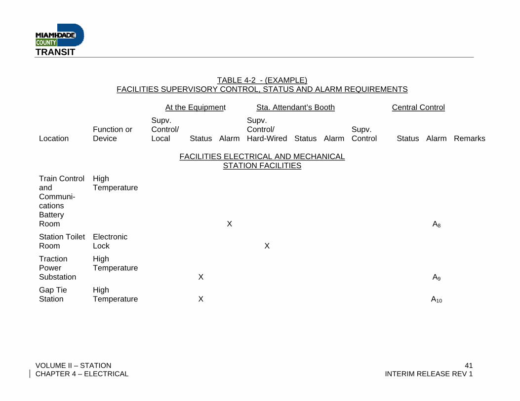
TABLE 4-2 - (EXAMPLE) FACILITIES SUPERVISORY CONTROL, STATUS AND ALARM REQUIREMENTS
At the Equipment Sta. Attendant’s Booth Central Control
Location Function or Device
Supv. Control/ Local Status Alarm
Supv. Control/ Hard-Wired Status Alarm
Supv. Control Status Alarm Remarks
FACILITIES ELECTRICAL AND MECHANICAL
STATION FACILITIES Train Control and Communi-cations Battery Room
High Temperature
X
A8
Station Toilet Room
Electronic Lock X
Traction Power Substation
High Temperature
X A9
Gap Tie Station
High Temperature X A10
TRANSIT
VOLUME II – STATION 42 CHAPTER 4 – ELECTRICAL INTERIM RELEASE REV 1
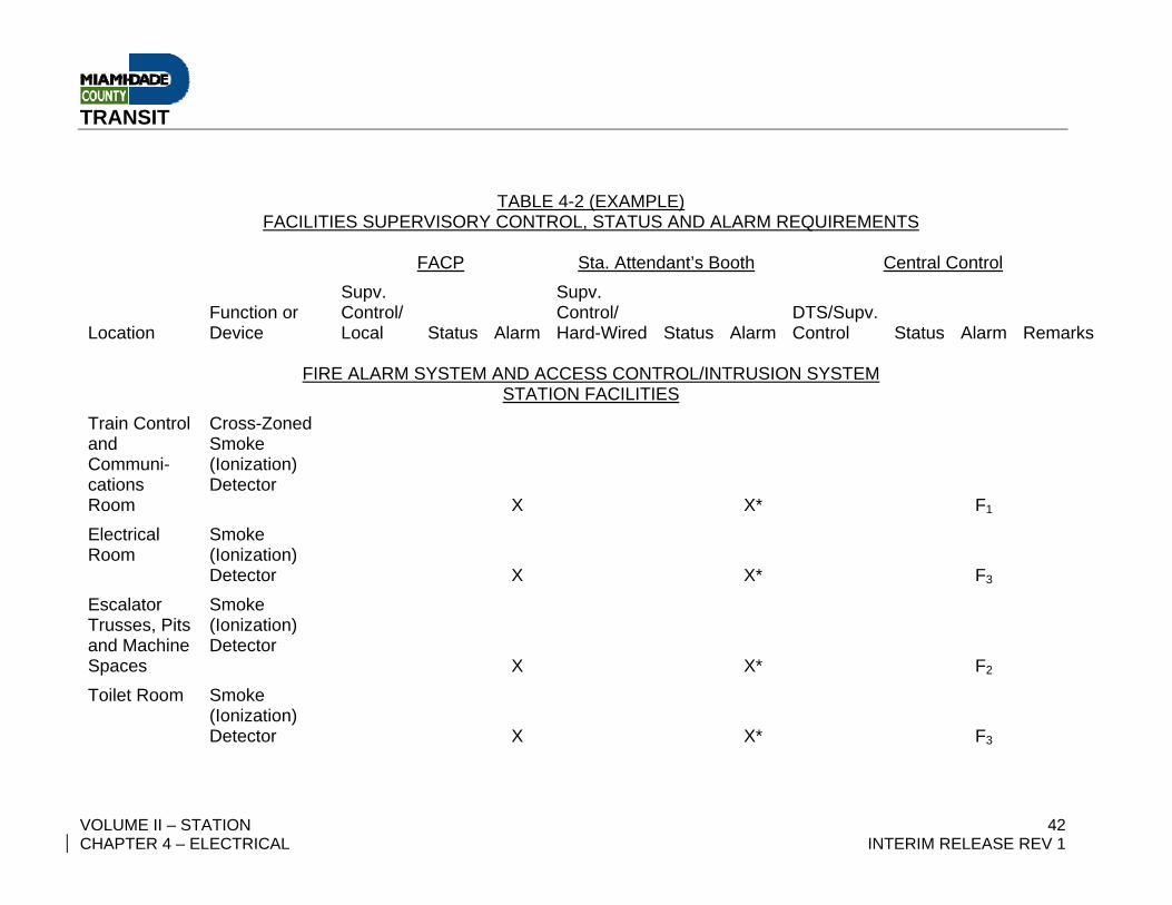
TABLE 4-2 (EXAMPLE)
FACILITIES SUPERVISORY CONTROL, STATUS AND ALARM REQUIREMENTS FACP Sta. Attendant’s Booth Central Control
Location Function or Device
Supv. Control/ Local Status Alarm
Supv. Control/ Hard-Wired Status Alarm
DTS/Supv. Control Status Alarm Remarks
FIRE ALARM SYSTEM AND ACCESS CONTROL/INTRUSION SYSTEM
STATION FACILITIES Train Control and Communi-cations Room
Cross-Zoned Smoke (Ionization) Detector
X X* F1
Electrical Room
Smoke (Ionization) Detector X X* F3
Escalator Trusses, Pits and Machine Spaces
Smoke (Ionization) Detector
X X* F2
Toilet Room Smoke (Ionization) Detector
X X*
F3
TRANSIT
VOLUME II – STATION 43 CHAPTER 4 – ELECTRICAL INTERIM RELEASE REV 1
TABLE 4-2 (EXAMPLE) FACILITIES SUPERVISORY CONTROL, STATUS AND ALARM REQUIREMENTS
FACP Sta. Attendant’s Booth Central Control
Location Function or Device
Supv. Control/ Local Status Alarm
Supv. Control/ Hard-Wired Status Alarm
DTS/Supv. Control Status Alarm Remarks
FIRE ALARM SYSTEM AND ACCESS CONTROL/INTRUSION SYSTEM
STATION FACILITIES Supply Ducts of Air Condi-tioning System
Smoke (Ionization) Detector
X X*
F3
Return Air Ducts and After Filters in Air Condi-tioning System
Smoke (Ionization) Detector
X X*
F3
Elevator Machine Rooms
Smoke (Ionization) Detector
X X*
F2
Revenue Rooms
Smoke (Ionization) Detector
X X*
F3
TRANSIT
VOLUME II – STATION 44 CHAPTER 4 – ELECTRICAL INTERIM RELEASE REV 1
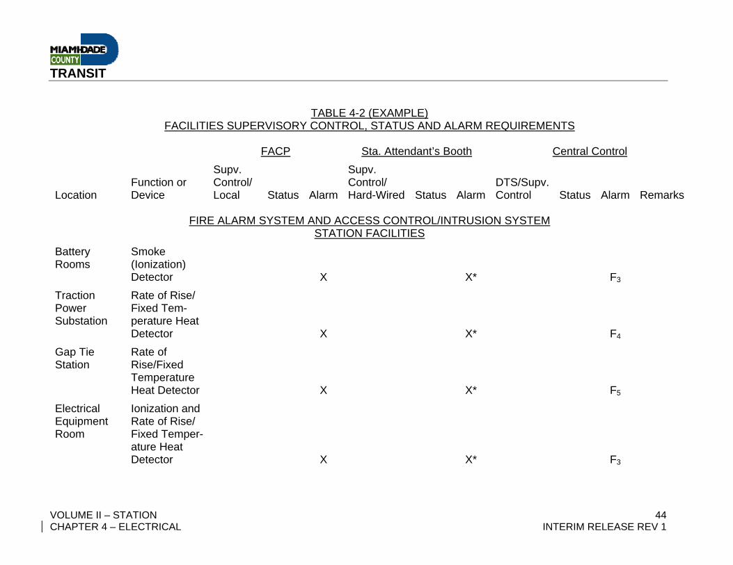
TABLE 4-2 (EXAMPLE) FACILITIES SUPERVISORY CONTROL, STATUS AND ALARM REQUIREMENTS
FACP Sta. Attendant’s Booth Central Control
Location Function or Device
Supv. Control/ Local Status Alarm
Supv. Control/ Hard-Wired Status Alarm
DTS/Supv. Control Status Alarm Remarks
FIRE ALARM SYSTEM AND ACCESS CONTROL/INTRUSION SYSTEM
STATION FACILITIES Battery Rooms
Smoke (Ionization) Detector
X X* F3
Traction Power Substation
Rate of Rise/ Fixed Tem-perature Heat Detector
X X* F4
Gap Tie Station
Rate of Rise/Fixed Temperature Heat Detector
X X* F5
Electrical Equipment Room
Ionization and Rate of Rise/ Fixed Temper-ature Heat Detector
X X* F3
TRANSIT
VOLUME II – STATION 45 CHAPTER 4 – ELECTRICAL INTERIM RELEASE REV 1
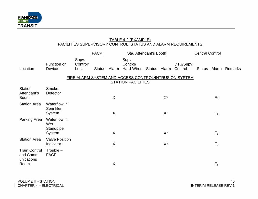
TABLE 4-2 (EXAMPLE) FACILITIES SUPERVISORY CONTROL, STATUS AND ALARM REQUIREMENTS
FACP Sta. Attendant’s Booth Central Control
Location Function or Device
Supv. Control/ Local Status Alarm
Supv. Control/ Hard-Wired Status Alarm
DTS/Supv. Control Status Alarm Remarks
FIRE ALARM SYSTEM AND ACCESS CONTROL/INTRUSION SYSTEM
STATION FACILITIES Station Attendant’s Booth
Smoke Detector
X X* F3
Station Area Waterflow in Sprinkler System
X X* F6
Parking Area Waterflow in Wet Standpipe System
X X* F6
Station Area Valve Position Indicator
X X* F7
Train Control and Comm-unications Room
Trouble – FACP
X F8
TRANSIT
VOLUME II – STATION 46 CHAPTER 4 – ELECTRICAL INTERIM RELEASE REV 1
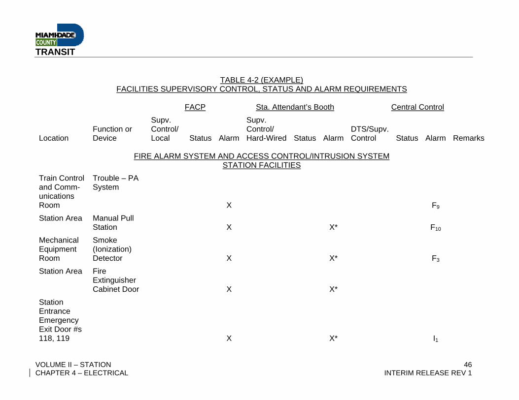
TABLE 4-2 (EXAMPLE) FACILITIES SUPERVISORY CONTROL, STATUS AND ALARM REQUIREMENTS
FACP Sta. Attendant’s Booth Central Control
Location Function or Device
Supv. Control/ Local Status Alarm
Supv. Control/ Hard-Wired Status Alarm
DTS/Supv. Control Status Alarm Remarks
FIRE ALARM SYSTEM AND ACCESS CONTROL/INTRUSION SYSTEM
STATION FACILITIES Train Control and Comm-unications Room
Trouble – PA System
X F9
Station Area Manual Pull Station
X X* F10
Mechanical Equipment Room
Smoke (Ionization) Detector
X X* F3
Station Area Fire Extinguisher Cabinet Door
X X*
Station Entrance Emergency Exit Door #s 118, 119
X X* I1
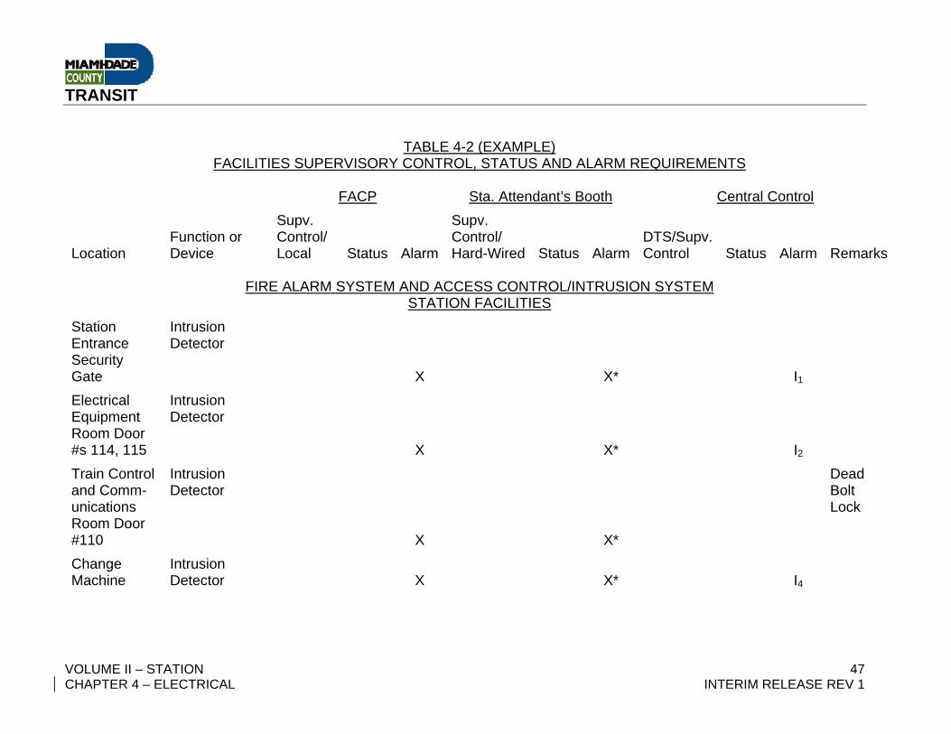
TRANSIT
VOLUME II – STATION 47 CHAPTER 4 – ELECTRICAL INTERIM RELEASE REV 1
TABLE 4-2 (EXAMPLE) FACILITIES SUPERVISORY CONTROL, STATUS AND ALARM REQUIREMENTS
FACP Sta. Attendant’s Booth Central Control
Location Function or Device
Supv. Control/ Local Status Alarm
Supv. Control/ Hard-Wired Status Alarm
DTS/Supv. Control Status Alarm Remarks
FIRE ALARM SYSTEM AND ACCESS CONTROL/INTRUSION SYSTEM
STATION FACILITIES Station Entrance Security Gate
Intrusion Detector
X X* I1
Electrical Equipment Room Door #s 114, 115
Intrusion Detector
X X* I2
Train Control and Comm-unications Room Door #110
Intrusion Detector
X X*
Dead Bolt Lock
Change Machine
Intrusion Detector
X X* I4
TRANSIT
VOLUME II – STATION 48 CHAPTER 4 – ELECTRICAL INTERIM RELEASE REV 1
TABLE 4-2 (EXAMPLE) FACILITIES SUPERVISORY CONTROL, STATUS AND ALARM REQUIREMENTS
FACP Sta. Attendant’s Booth Central Control
Location Function or Device
Supv. Control/ Local Status Alarm
Supv. Control/ Hard-Wired Status Alarm
DTS/Supv. Control Status Alarm Remarks
FIRE ALARM SYSTEM AND ACCESS CONTROL/INTRUSION SYSTEM
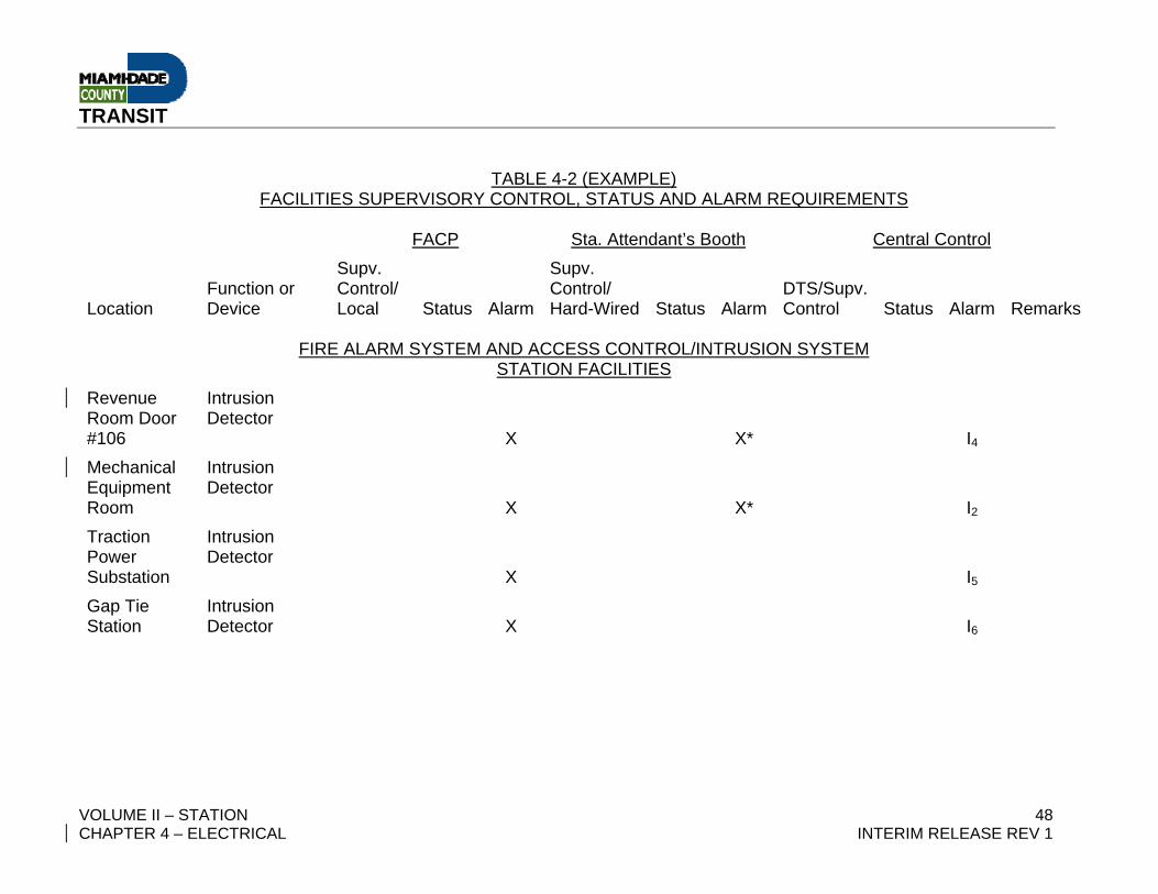
STATION FACILITIES Revenue Room Door #106
Intrusion Detector
X X* I4
Mechanical Equipment Room
Intrusion Detector
X X* I2
Traction Power Substation
Intrusion Detector
X I5
Gap Tie Station
Intrusion Detector
X I6
TRANSIT
VOLUME II – STATION 49 CHAPTER 4 – ELECTRICAL INTERIM RELEASE REV 1
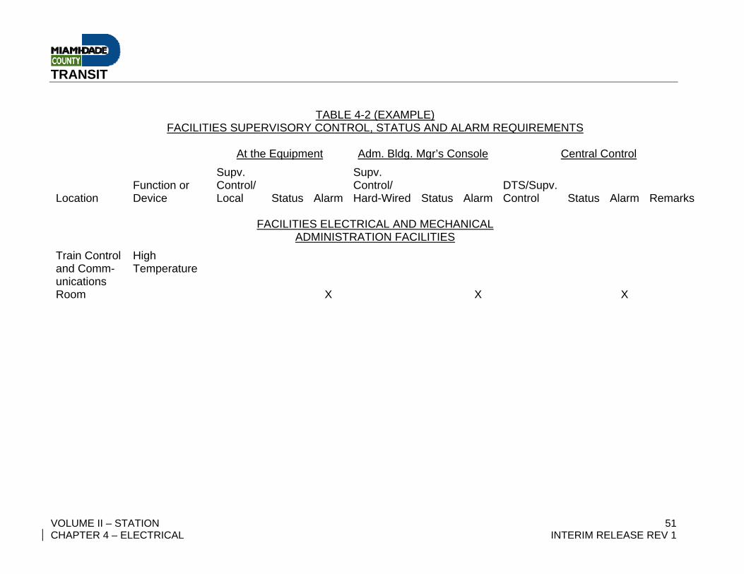
TABLE 4-2 (EXAMPLE)
FACILITIES SUPERVISORY CONTROL, STATUS AND ALARM REQUIREMENTS At the Equipment Adm. Bldg. Mgr’s Console Central Control
Location Function or Device
Supv. Control/ Local Status Alarm
Supv. Control/ Hard-Wired Status Alarm
DTS/Supv. Control Status Alarm Remarks
FACILITIES ELECTRICAL AND MECHANICAL
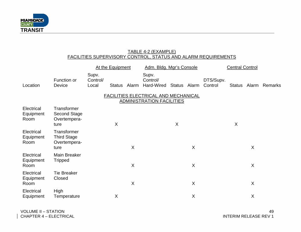
ADMINISTRATION FACILITIES Electrical Equipment Room
Transformer Second Stage Overtempera-ture
X
X
X
Electrical Equipment Room
Transformer Third Stage Overtempera-ture
X
X
X
Electrical Equipment Room
Main Breaker Tripped
X
X
X
Electrical Equipment Room
Tie Breaker Closed
X
X
X
Electrical Equipment
High Temperature
X
X
X
TRANSIT
VOLUME II – STATION 50 CHAPTER 4 – ELECTRICAL INTERIM RELEASE REV 1
TABLE 4-2 (EXAMPLE) FACILITIES SUPERVISORY CONTROL, STATUS AND ALARM REQUIREMENTS
At the Equipment Adm. Bldg. Mgr’s Console Central Control
Location Function or Device
Supv. Control/ Local Status Alarm
Supv. Control/ Hard-Wired Status Alarm
DTS/Supv. Control Status Alarm Remarks
FACILITIES ELECTRICAL AND MECHANICAL
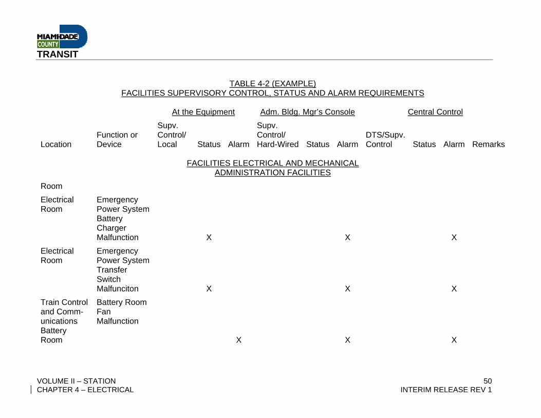
ADMINISTRATION FACILITIES Room Electrical Room
Emergency Power System Battery Charger Malfunction
X
X
X
Electrical Room
Emergency Power System Transfer Switch Malfunciton
X
X
X
Train Control and Comm-unications Battery Room
Battery Room Fan Malfunction
X
X
X
TRANSIT
VOLUME II – STATION 51 CHAPTER 4 – ELECTRICAL INTERIM RELEASE REV 1
TABLE 4-2 (EXAMPLE) FACILITIES SUPERVISORY CONTROL, STATUS AND ALARM REQUIREMENTS
At the Equipment Adm. Bldg. Mgr’s Console Central Control
Location Function or Device
Supv. Control/ Local Status Alarm
Supv. Control/ Hard-Wired Status Alarm
DTS/Supv. Control Status Alarm Remarks
FACILITIES ELECTRICAL AND MECHANICAL
ADMINISTRATION FACILITIES Train Control and Comm-unications Room
High Temperature
X
X
X
TRANSIT
VOLUME II – STATION 52 CHAPTER 4 – ELECTRICAL INTERIM RELEASE REV 1
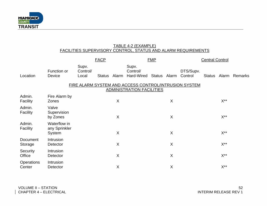
TABLE 4-2 (EXAMPLE)
FACILITIES SUPERVISORY CONTROL, STATUS AND ALARM REQUIREMENTS FACP FMP Central Control
Location Function or Device
Supv. Control/ Local Status Alarm
Supv. Control/ Hard-Wired Status Alarm
DTS/Supv. Control Status Alarm Remarks
FIRE ALARM SYSTEM AND ACCESS CONTROL/INTRUSION SYSTEM
ADMINISTRATION FACILITIES Admin. Facility
Fire Alarm by Zones
X
X
X**
Admin. Facility
Valve Supervision by Zones
X
X
X**
Admin. Facility
Waterflow in any Sprinkler System
X
X
X**
Document Storage
Intrusion Detector
X
X
X**
Security Office
Intrusion Detector
X
X
X**
Operations Center
Intrusion Detector
X
X
X**
TRANSIT
VOLUME II – STATION 53 CHAPTER 4 – ELECTRICAL INTERIM RELEASE REV 1
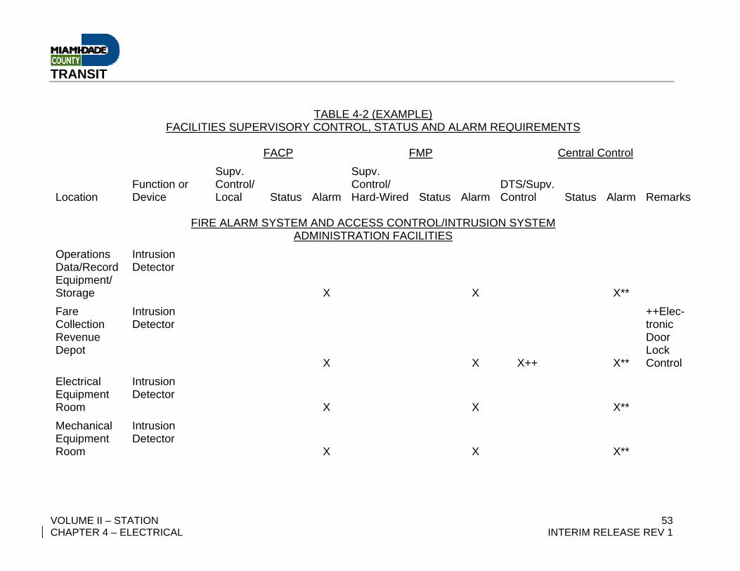
TABLE 4-2 (EXAMPLE) FACILITIES SUPERVISORY CONTROL, STATUS AND ALARM REQUIREMENTS
FACP FMP Central Control
Location Function or Device
Supv. Control/ Local Status Alarm
Supv. Control/ Hard-Wired Status Alarm
DTS/Supv. Control Status Alarm Remarks
FIRE ALARM SYSTEM AND ACCESS CONTROL/INTRUSION SYSTEM
ADMINISTRATION FACILITIES Operations Data/Record Equipment/ Storage
Intrusion Detector
X
X
X**
Fare Collection Revenue Depot
Intrusion Detector
X
X X++ X**
++Elec-tronic Door Lock Control
Electrical Equipment Room
Intrusion Detector
X
X X**
Mechanical Equipment Room
Intrusion Detector
X
X X**
TRANSIT
VOLUME II – STATION 54 CHAPTER 4 – ELECTRICAL INTERIM RELEASE REV 1
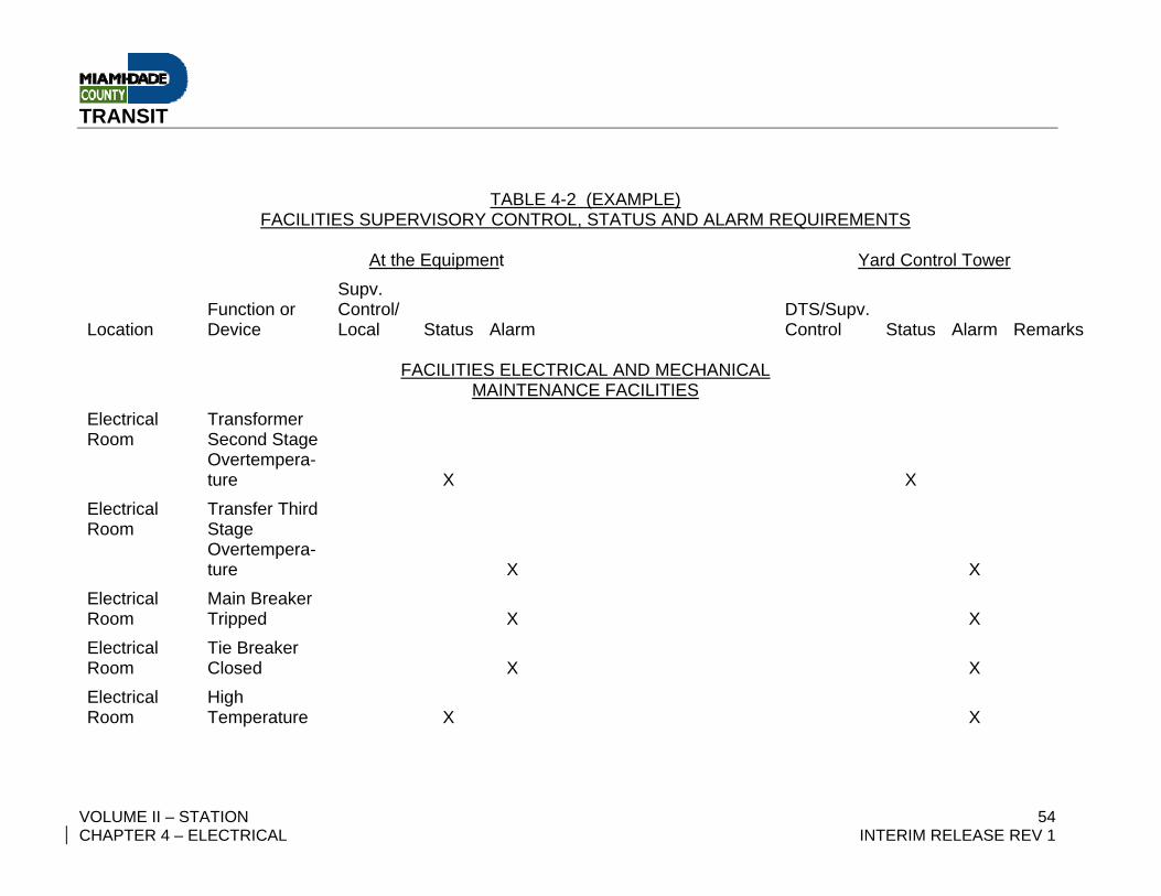
TABLE 4-2 (EXAMPLE)
FACILITIES SUPERVISORY CONTROL, STATUS AND ALARM REQUIREMENTS At the Equipment Yard Control Tower
Location Function or Device
Supv. Control/ Local Status Alarm
DTS/Supv. Control Status Alarm Remarks
FACILITIES ELECTRICAL AND MECHANICAL
MAINTENANCE FACILITIES Electrical Room
Transformer Second Stage Overtempera-ture
X
X
Electrical Room
Transfer Third Stage Overtempera-ture
X
X
Electrical Room
Main Breaker Tripped
X
X
Electrical Room
Tie Breaker Closed
X
X
Electrical Room
High Temperature
X
X
TRANSIT
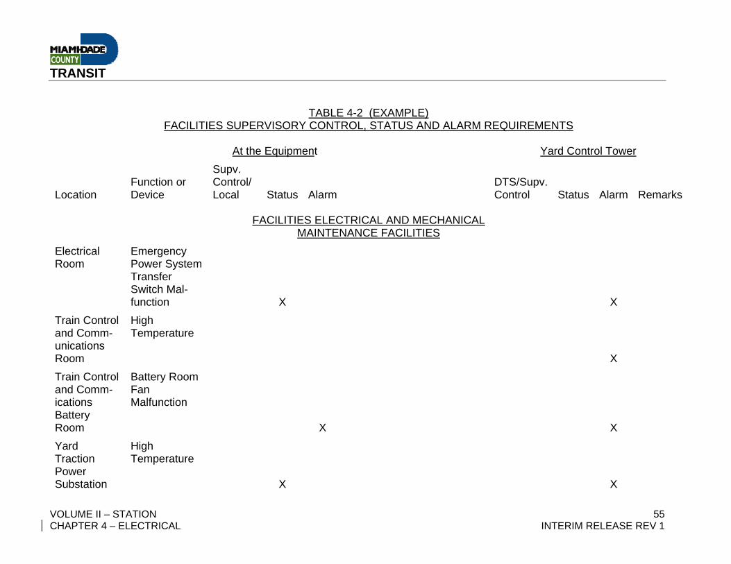
VOLUME II – STATION 55 CHAPTER 4 – ELECTRICAL INTERIM RELEASE REV 1
TABLE 4-2 (EXAMPLE) FACILITIES SUPERVISORY CONTROL, STATUS AND ALARM REQUIREMENTS
At the Equipment Yard Control Tower
Location Function or Device
Supv. Control/ Local Status Alarm
DTS/Supv. Control Status Alarm Remarks
FACILITIES ELECTRICAL AND MECHANICAL
MAINTENANCE FACILITIES Electrical Room
Emergency Power System Transfer Switch Mal-function
X
X
Train Control and Comm-unications Room
High Temperature
X
Train Control and Comm-ications Battery Room
Battery Room Fan Malfunction
X
X
Yard Traction Power Substation
High Temperature
X
X
TRANSIT
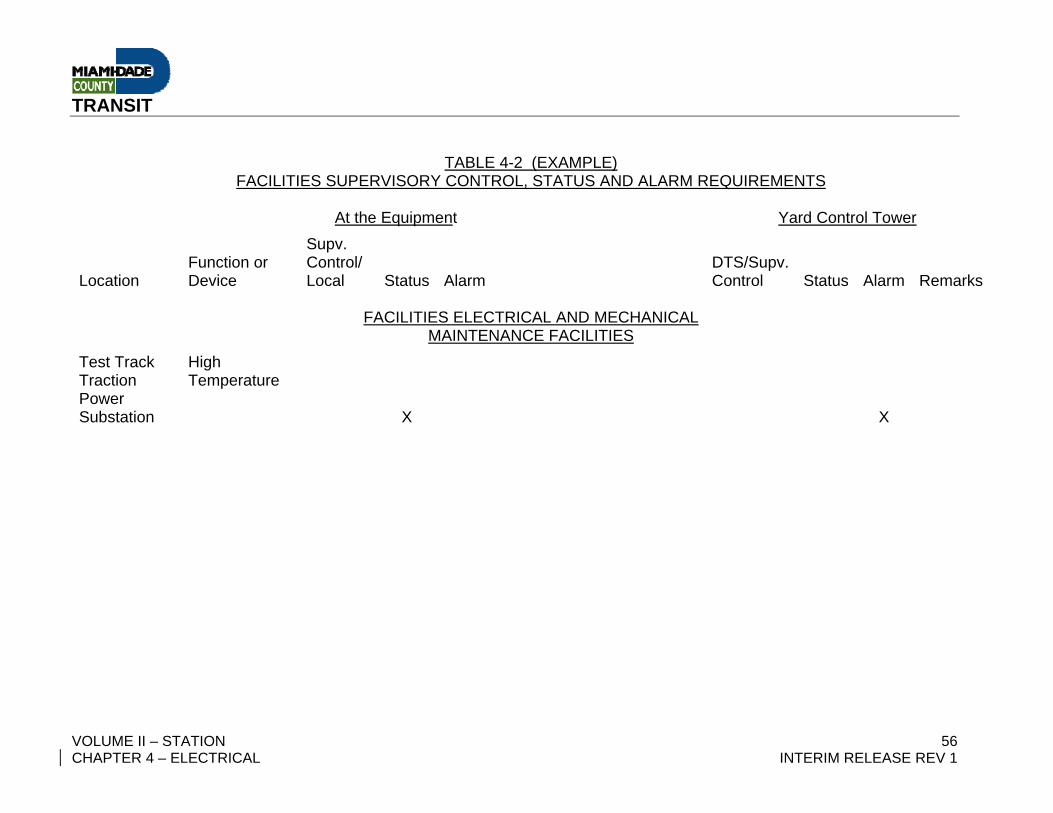
VOLUME II – STATION 56 CHAPTER 4 – ELECTRICAL INTERIM RELEASE REV 1
TABLE 4-2 (EXAMPLE) FACILITIES SUPERVISORY CONTROL, STATUS AND ALARM REQUIREMENTS
At the Equipment Yard Control Tower
Location Function or Device
Supv. Control/ Local Status Alarm
DTS/Supv. Control Status Alarm Remarks
FACILITIES ELECTRICAL AND MECHANICAL
MAINTENANCE FACILITIES Test Track Traction Power Substation
High Temperature
X
X
TRANSIT
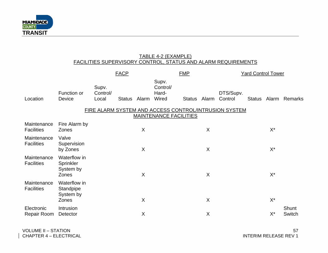
VOLUME II – STATION 57 CHAPTER 4 – ELECTRICAL INTERIM RELEASE REV 1
TABLE 4-2 (EXAMPLE)
FACILITIES SUPERVISORY CONTROL, STATUS AND ALARM REQUIREMENTS FACP FMP Yard Control Tower
Location Function or Device
Supv. Control/ Local Status Alarm
Supv. Control/ Hard-Wired Status Alarm
DTS/Supv. Control Status Alarm Remarks
FIRE ALARM SYSTEM AND ACCESS CONTROL/INTRUSION SYSTEM
MAINTENANCE FACILITIES Maintenance Facilities
Fire Alarm by Zones
X
X
X*
Maintenance Facilities
Valve Supervision by Zones
X
X
X*
Maintenance Facilities
Waterflow in Sprinkler System by Zones
X
X
X*
Maintenance Facilities
Waterflow in Standpipe System by Zones
X
X
X*
Electronic Repair Room
Intrusion Detector
X
X
X*
Shunt Switch
TRANSIT
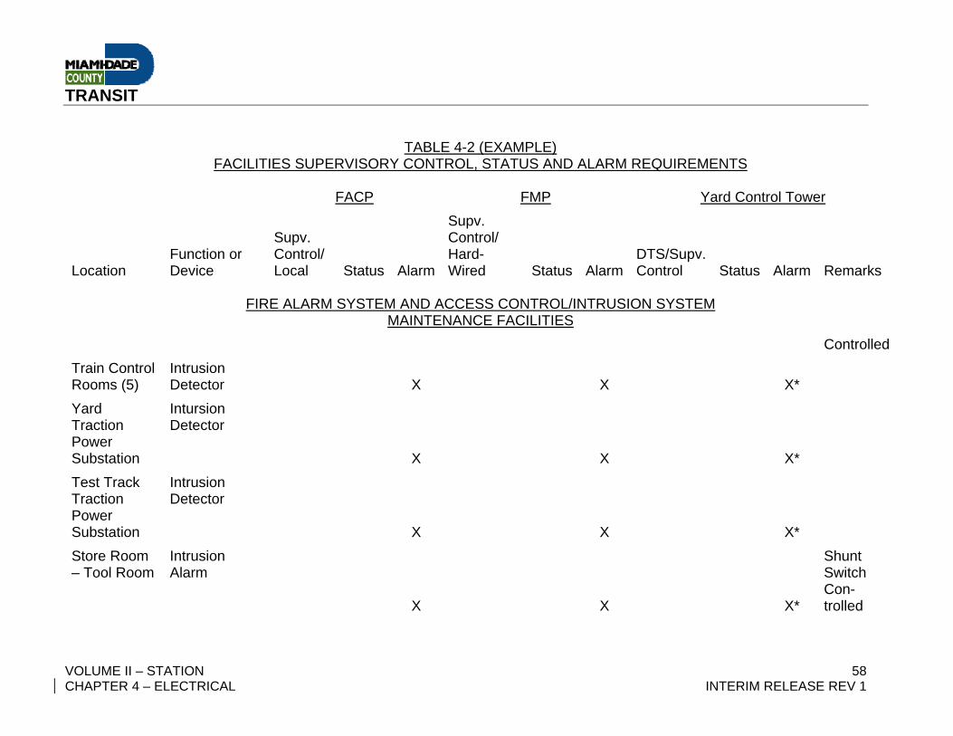
VOLUME II – STATION 58 CHAPTER 4 – ELECTRICAL INTERIM RELEASE REV 1
TABLE 4-2 (EXAMPLE) FACILITIES SUPERVISORY CONTROL, STATUS AND ALARM REQUIREMENTS
FACP FMP Yard Control Tower
Location Function or Device
Supv. Control/ Local Status Alarm
Supv. Control/ Hard-Wired Status Alarm
DTS/Supv. Control Status Alarm Remarks
FIRE ALARM SYSTEM AND ACCESS CONTROL/INTRUSION SYSTEM
MAINTENANCE FACILITIES Controlled
Train Control Rooms (5)
Intrusion Detector
X
X
X*
Yard Traction Power Substation
Intursion Detector
X X X*
Test Track Traction Power Substation
Intrusion Detector
X X X*
Store Room – Tool Room
Intrusion Alarm
X X X*
Shunt Switch Con-trolled

TRANSIT
VOLUME II – STATION 59 CHAPTER 4 – ELECTRICAL INTERIM RELEASE REV 1
TABLE 4-2 (EXAMPLE) FACILITIES SUPERVISORY CONTROL, STATUS AND ALARM REQUIREMENTS
FACP FMP Yard Control Tower
Location Function or Device
Supv. Control/ Local Status Alarm
Supv. Control/ Hard-Wired Status Alarm
DTS/Supv. Control Status Alarm Remarks
FIRE ALARM SYSTEM AND ACCESS CONTROL/INTRUSION SYSTEM
MAINTENANCE FACILITIES Electrical Equipment Room
Intrusion Detector
X X X*
TRANSIT
VOLUME II – STATION 60 CHAPTER 4 – ELECTRICAL INTERIM RELEASE REV 1
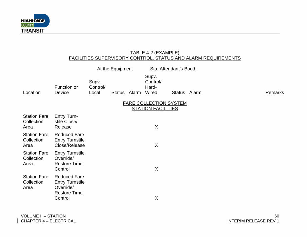
TABLE 4-2 (EXAMPLE)
FACILITIES SUPERVISORY CONTROL, STATUS AND ALARM REQUIREMENTS At the Equipment Sta. Attendant’s Booth
Location Function or Device
Supv. Control/ Local Status Alarm
Supv. Control/ Hard-Wired Status Alarm Remarks
FARE COLLECTION SYSTEM
STATION FACILITIES Station Fare Collection Area
Entry Turn-stile Close/ Release X
Station Fare Collection Area
Reduced Fare Entry Turnstile Close/Release X
Station Fare Collection Area
Entry Turnstile Override/ Restore Time Control X
Station Fare Collection Area
Reduced Fare Entry Turnstile Override/ Restore Time Control X
TRANSIT
VOLUME II – STATION 61 CHAPTER 4 – ELECTRICAL INTERIM RELEASE REV 1
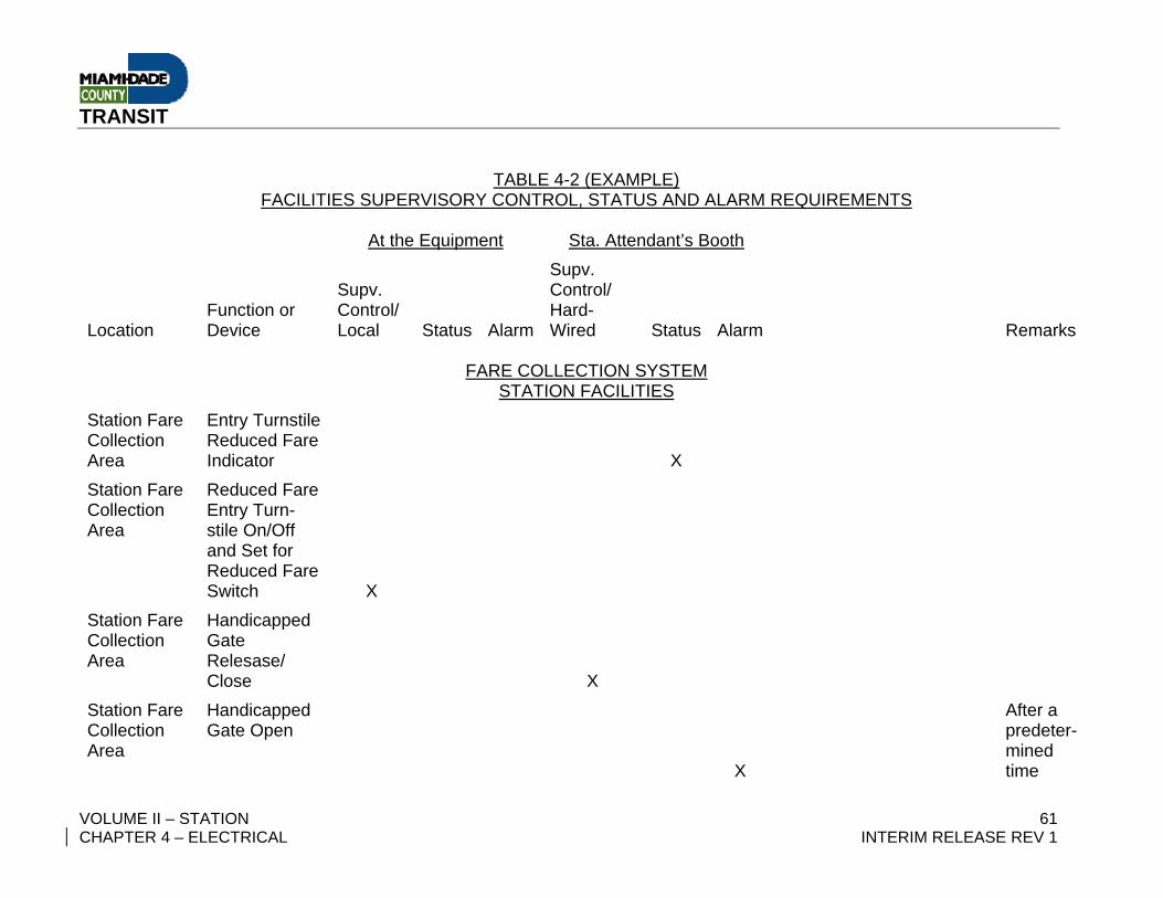
TABLE 4-2 (EXAMPLE) FACILITIES SUPERVISORY CONTROL, STATUS AND ALARM REQUIREMENTS
At the Equipment Sta. Attendant’s Booth
Location Function or Device
Supv. Control/ Local Status Alarm
Supv. Control/ Hard-Wired Status Alarm Remarks
FARE COLLECTION SYSTEM
STATION FACILITIES Station Fare Collection Area
Entry Turnstile Reduced Fare Indicator X
Station Fare Collection Area
Reduced Fare Entry Turn-stile On/Off and Set for Reduced Fare Switch X
Station Fare Collection Area
Handicapped Gate Relesase/ Close X
Station Fare Collection Area
Handicapped Gate Open
X
After a predeter-mined time
TRANSIT
VOLUME II – STATION 62 CHAPTER 4 – ELECTRICAL INTERIM RELEASE REV 1
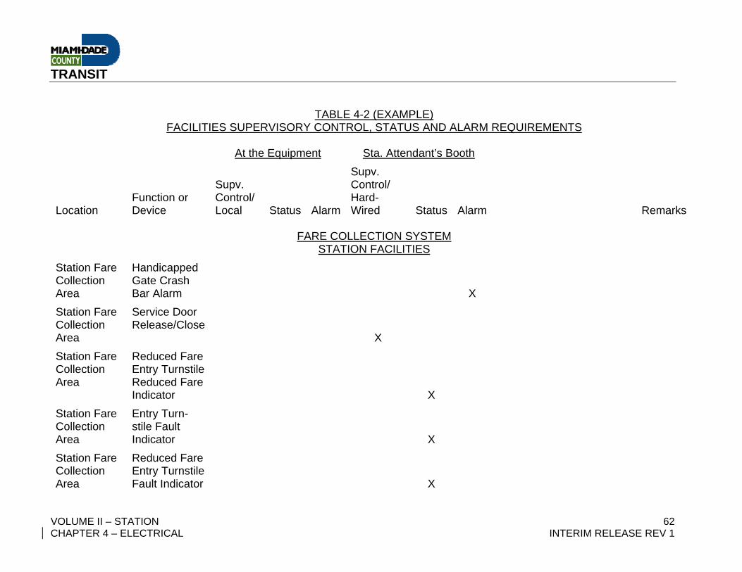
TABLE 4-2 (EXAMPLE) FACILITIES SUPERVISORY CONTROL, STATUS AND ALARM REQUIREMENTS
At the Equipment Sta. Attendant’s Booth
Location Function or Device
Supv. Control/ Local Status Alarm
Supv. Control/ Hard-Wired Status Alarm Remarks
FARE COLLECTION SYSTEM
STATION FACILITIES Station Fare Collection Area
Handicapped Gate Crash Bar Alarm X
Station Fare Collection Area
Service Door Release/Close
X
Station Fare Collection Area
Reduced Fare Entry Turnstile Reduced Fare Indicator X
Station Fare Collection Area
Entry Turn-stile Fault Indicator X
Station Fare Collection Area
Reduced Fare Entry Turnstile Fault Indicator X
TRANSIT
VOLUME II – STATION 63 CHAPTER 4 – ELECTRICAL INTERIM RELEASE REV 1
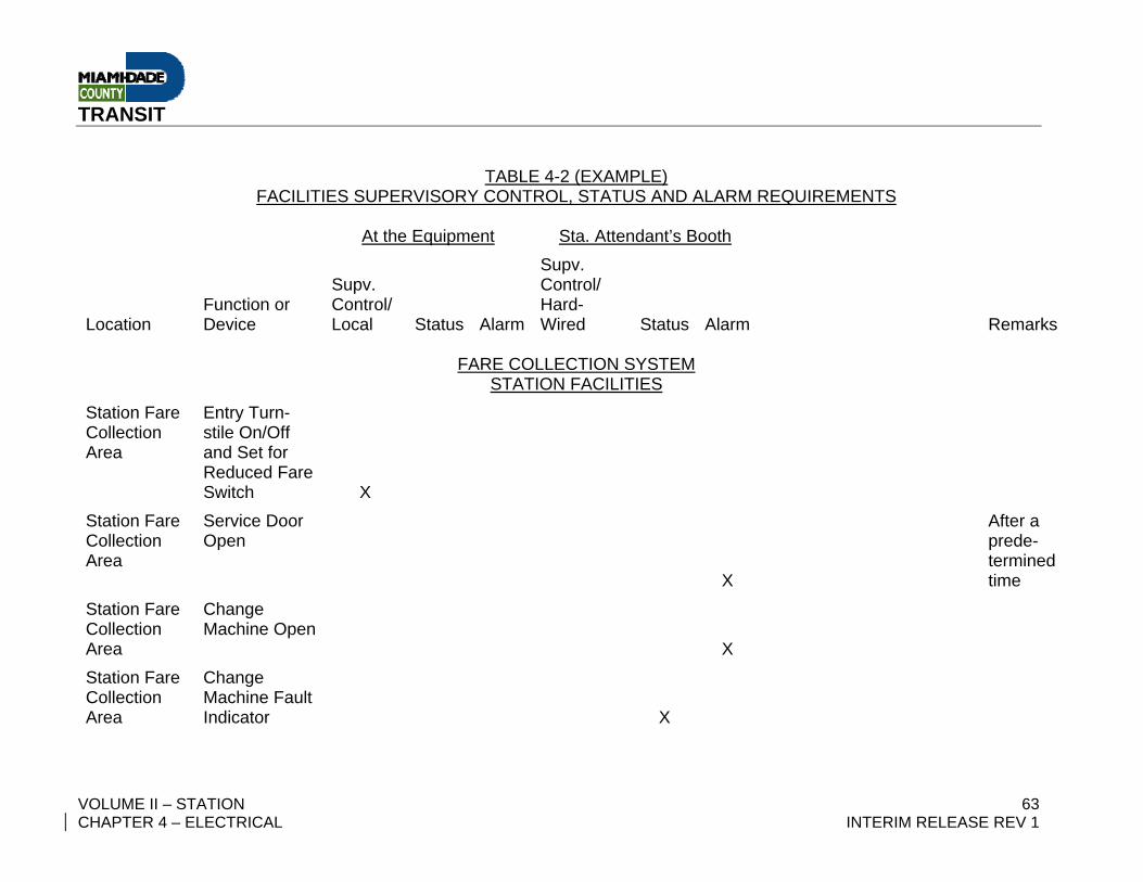
TABLE 4-2 (EXAMPLE) FACILITIES SUPERVISORY CONTROL, STATUS AND ALARM REQUIREMENTS
At the Equipment Sta. Attendant’s Booth
Location Function or Device
Supv. Control/ Local Status Alarm
Supv. Control/ Hard-Wired Status Alarm Remarks
FARE COLLECTION SYSTEM
STATION FACILITIES Station Fare Collection Area
Entry Turn-stile On/Off and Set for Reduced Fare Switch X
Station Fare Collection Area
Service Door Open
X
After a prede-termined time
Station Fare Collection Area
Change Machine Open
X
Station Fare Collection Area
Change Machine Fault Indicator X
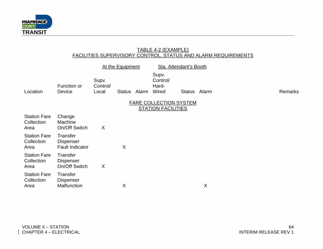
TRANSIT
VOLUME II – STATION 64 CHAPTER 4 – ELECTRICAL INTERIM RELEASE REV 1
TABLE 4-2 (EXAMPLE) FACILITIES SUPERVISORY CONTROL, STATUS AND ALARM REQUIREMENTS
At the Equipment Sta. Attendant’s Booth
Location Function or Device
Supv. Control/ Local Status Alarm
Supv. Control/ Hard-Wired Status Alarm Remarks
FARE COLLECTION SYSTEM
STATION FACILITIES Station Fare Collection Area
Change Machine On/Off Switch X
Station Fare Collection Area
Transfer Dispenser Fault Indicator X
Station Fare Collection Area
Transfer Dispenser On/Off Switch X
Station Fare Collection Area
Transfer Dispenser Malfunction X X
TRANSIT
VOLUME II – STATION 65 CHAPTER 4 – ELECTRICAL INTERIM RELEASE REV 1
4.04 GROUNDING AND LIGHTNING PROTECTION (Reserved) 4.04.1 SCOPE (Reserved)
Refer to: Volume III – Guideway Design, Chapter 4 – Guideway Electrical, for
the grounding and lightning protection systems design criteria applicable to
the Metrorail Line Extension.
4.04.2 OBJECTIVE (Reserved) Refer to: Volume III – Guideway Design, Chapter 4 – Guideway Electrical
4.04.3 ABNORMAL CONDITIONS (Reserved) Refer to: Volume III – Guideway Design, Chapter 4 – Guideway Electrical
4.04.4 GROUNDING ELECTRODE SYSTEM (Reserved) Refer to: Volume III – Guideway Design, Chapter 4 – Guideway Electrical
4.04.5 TRACTION POWER GROUNDING (Reserved) Refer to: Volume III – Guideway Design, Chapter 4 – Guideway Electrical
4.04.6 SECONDARY POWER DISTRIBUTION SYSTEM GROUNDING (Reserved) Refer to: Volume III – Guideway Design, Chapter 4 – Guideway Electrical
4.04.7 GROUNDING NETWORKS (Reserved) Refer to: Volume III – Guideway Design, Chapter 4 – Guideway Electrical
4.04.8 LIGHTNING PROTECTION (Reserved) Refer to: Volume III – Guideway Design, Chapter 4 – Guideway Electrical

TRANSIT
VOLUME II – STATION 66 CHAPTER 4 – ELECTRICAL INTERIM RELEASE REV 1
– Intentionally Left Blank –
TRANSIT
VOLUME II – STATION 67 CHAPTER 4 – ELECTRICAL INTERIM RELEASE REV 1
4.05 CORROSION CONTROL (Reserved) 4.05.1 SCOPE (Reserved)
Refer to: Volume III – Guideway Design, Chapter 4 – Guideway Electrical, for
the corrosion control design criteria applicable to the Metrorail Line Extension.
4.05.2 CONTROL OF ATMOSPHERIC CORROSION (Reserved) Refer to: Volume III – Guideway Design, Chapter 4 – Guideway Electrical
4.05.3 STRAY CURRENT CORROSION CONTROL (Reserved) Refer to: Volume III – Guideway Design, Chapter 4 – Guideway Electrical
4.05.4 CATHODIC PROTECTION (Reserved) Refer to: Volume III – Guideway Design, Chapter 4 – Guideway Electrical
4.05.5 TEST STATIONS (Reserved) Refer to: Volume III – Guideway Design, Chapter 4 – Guideway Electrical
4.05.6 CORROSION CONTROL OF MECHANICAL EQUIPMENT (Reserved) Refer to: Volume III – Guideway Design, Chapter 4 – Guideway Electrical
Refer also to: This Volume, Chapter 5, Mechanical Design Criteria
4.05.7 MISCELLANEOUS ITEMS (Reserved) Refer to: Volume III – Guideway Design, Chapter 4 – Guideway Electrical

TRANSIT
VOLUME II – STATION 68 CHAPTER 4 – ELECTRICAL INTERIM RELEASE REV 1
– Intentionally Left Blank –
TRANSIT
VOLUME II – STATION 69 CHAPTER 4 – ELECTRICAL INTERIM RELEASE REV 1
4.06 SYSTEMS-FACILITIES INTERFACE RACEWAY (Reserved)
Refer to: Volume III – Guideway Design, Chapter 4 – Guideway Electrical, for
the Systems-Facilities Interface Raceway design criteria.
4.06.1 SCOPE (Reserved) Refer to: Volume III – Guideway Design, Chapter 4 – Guideway Electrical
4.06.2 PHYSICAL RELATIONSHIP (Reserved) Refer to: Volume III – Guideway Design, Chapter 4 – Guideway Electrical
4.06.3 PHYSICAL INSTALLATION (Reserved) Refer to: Volume III – Guideway Design, Chapter 4 – Guideway Electrical
4.06.4 MATERIALS OF CONSTRUCTION (Reserved) Refer to: Volume III – Guideway Design, Chapter 4 – Guideway Electrical
4.06.5 RACEWAY IDENTIFICATION METHODS (Reserved) Refer to: Volume III – Guideway Design, Chapter 4 – Guideway Electrical

TRANSIT
VOLUME II – STATION 70 CHAPTER 4 – ELECTRICAL INTERIM RELEASE REV 1
– Intentionally Left Blank –
TRANSIT
VOLUME II – STATION 71 CHAPTER 4 – ELECTRICAL INTERIM RELEASE REV 1
4.07 LIGHTING DESIGN CRITERIA 4.07.1 INTRODUCTION
The Primary criterion for lighting is as follows:
"Lighting levels shall be established (by accepted standards and applicable
codes) to provide for comfort, safety and amenity of the system user. Lighting
shall be designed to be maintenance friendly, in a glare-free, orderly manner,
using long life, low power consumption, high lumen lamps whenever possible.
Emergency lighting shall also be provided to allow persons to safely exit the
system and facilities under prolonged primary outage conditions. Lighting
shall comply with the energy efficiency requirements of the Florida Building
Code. "
The lighting criteria contained herein is consistent with the above
requirements and is intended to provide the Section Designer with the
functional and aesthetic guidance necessary to design the lighting for site
areas, passenger stations, parking areas, walkways, traction power
substations, gap tie stations, and ancillary spaces.
See also Volume I, Systemwide Criteria - Chapter 7, System Safety Criteria;
Chapter 8, System Security Design Criteria; and Chapter 9, Fire/Life Safety
Criteria.
These documents supply specific solutions to repetitive problems of
illumination. The intent is to standardize components and mounting
configurations throughout the system. Adherence to these documents by all
lighting designers will insure consistent ambience for the system facilities, and
TRANSIT
VOLUME II – STATION 72 CHAPTER 4 – ELECTRICAL INTERIM RELEASE REV 1
provide the required maintainability, convenience, safety, and efficiency of the
transit system.
4.07.2 DESIGN OBJECTIVES The Extension Designer shall achieve the indicated illumination levels and
visual and functional clarity by using the selected standard design elements
provided by MDT, i.e., General Plans, Standard and Directive Drawings, and
applicable codes.
These standards unify the appearance and maintenance of the system, but
are not meant to preclude individual interpretation of interesting or stimulating
lighting treatments that may accent or reinforce particular architectural
features. The Designer shall be responsible for the applications of luminaries,
chosen from Luminary Palette, and their relationship to associated
environments, ceilings and supporting structures. Variation from standard
design elements is subject to review and specific prior approval by MDT.
The following guidelines are applicable to lighting design throughout the
transit system (specific area requirements are contained in subsequent
sections herein).
The lighting subsystem design and selection of lighting equipment shall be
made to minimize initial, maintenance and energy costs.
A High Intensity Discharge (H.I.D.) source shall be utilized for general site
and high-bay lighting. In general, fluorescent and H.I.D. sources shall provide
the required illumination for passenger stations, parking structures, and
interior spaces. Incandescent lamps shall be used to supplement pedestrian
TRANSIT
VOLUME II – STATION 73 CHAPTER 4 – ELECTRICAL INTERIM RELEASE REV 1
way illumination levels and for design accent but only with prior approval by
MDT.
The color rendering properties of the family of lamps chosen shall be used to
provide maximum color discrimination.
The illumination levels indicated shall define and differentiate between task
areas, decision and transition points, and areas of potential hazard. In
addition to quantity of light, it is essential that illumination for the system be
designed to minimize glare and provide uniform distribution. Luminaries shall
be so selected, located and/or aimed that, while accomplishing their primary
purpose, they shall produce a minimum of objectionable glare and/or
interference with task accuracy, vehicular traffic and neighboring areas.
Luminance in the visual field shall be as uniform as practicable with
brightness and contrast ratios minimized and veiling reflections eliminated or
effectively reduced. The following values shall apply as practical
standardization but are not applicable for small areas of lighting provided for
accent, design, interest or message purposes.
Brightness ratio
Wall to Floor 3:1
Wall to Ceiling 1:3
Luminaries to adjacent surfaces 20:1
Stairs and escalators to general
platform or concourse area 2:1
(in open area structures brightness ratios are undefined).
TRANSIT
VOLUME II – STATION 74 CHAPTER 4 – ELECTRICAL INTERIM RELEASE REV 1
The system shall provide a minimum Visual Comfort Probability (VCP) rating
of 75. VCP can be maximized through coordination with MDT on the selection
of ceiling, wall and floor finishes and colors. Generally, high reflectance
factors are desirable.
Ceilings 60 - 80%
Walls 40 - 60%
Floors 10 - 30%
4.07.3 CALCULATIONS The normal method of calculating illumination levels shall be as outlined in the
Illumination Engineering Society (IES) Lighting Handbook. The "lumen"
method shall be used in routine interior calculations. The IES "roadway"
method shall be used to calculate lighting levels for access lanes, open
parking areas and vehicle storage areas. The "point-by-point" method shall be
used for special locations as required.
Illumination levels for general interior spaces shall be in accordance with the
specified average maintained foot candle values on a horizontal plane 30
inches above the finished floor except emergency and parking structure
lighting, whose values shall be on a horizontal plane at the floor level.
Illumination uniformity will be acceptable if it is within 1/3 from the specified
average. Minimum site area illumination levels shall be calculated from the
"iso-foot candle" curves of the appropriate luminary. Uniformity for major site
lighting shall utilize the "average level-to-minimum point" method, and shall
not exceed a ratio of three to one. Coefficients of utilization shall be used to
determine the average level of illumination.
TRANSIT
VOLUME II – STATION 75 CHAPTER 4 – ELECTRICAL INTERIM RELEASE REV 1
Lighting used in small areas as a “Design Feature” shall be considered
supplementary to the required general illumination level for any particular
area. Such lighting design shall include backlit graphics, graphic and/or
advertising display units, and lighting intended to provide accent or sparkle
against the necessary background. Lighting used as a “Design Feature” shall
be subject to approval by MDT.
4.07.4 SITE AREAS 4.07.4.1 General
A. Site lighting provides for identification, unification, safety and security of
each facility. The lighting shall define the site organization by the
hierarchy of visual response through illumination levels, patterns, and
colors. For example, major traffic areas shall be strengthened by higher
intensity lighting, while subordinate elements such as walkways shall be
emphasized by visually subdued patterns of lighting and/or color,
thereby attracting and guiding both driver and pedestrian to the facility
entrance.
B. The standard site lighting elements shall distribute the output of
concealed sources efficiently over broad areas, creating a quickly,
recognizable "site identity" and "personality" of the site environment.
1. Station site lighting is concerned with internal site circulation and
access to station. The placement of luminaries shall not obstruct
the movement and parking of vehicles. Luminary placement shall
be coordinated with the landscape and parking plan to protect light
standards which may occur directly adjacent to parking stalls and to
ensure that plantings will not obscure the lighting distribution
pattern.
TRANSIT
VOLUME II – STATION 76 CHAPTER 4 – ELECTRICAL INTERIM RELEASE REV 1
2. Vehicular access lighting shall provide a natural lead in to the bus
loading/unloading, kiss-and-ride, and park-and-ride areas. The
illumination on all access and egress roads shall be graduated up
or down to the illumination level of the "feeder" street or highway.
3. Pedestrian access lighting shall define pedestrian walkways,
crosswalks, ramps, stairs and bridges.
4. Landscape lighting is an element which shall reinforce the variety,
color and texture of the landscape design, and is subject to
approval by MDT.
5. Park-and-Ride lighting shall be an extension of the access-way
lighting environment, but shall be made brighter by additional
lighting elements placed between the ranks of automobiles and in
pedestrian access-ways. Parking occupies the largest single area
of the transit station site and its lighting shall be used to define the
parking area perimeter, not only as the principal location of light
sources at night, but as a visible architectural element bounded by
regularly spaced standards during daylight hours.
For illumination levels, see Table 4-3.
4.07.5 PASSENGER STATIONS A. General
Station lighting shall be integrated with the structure to form a systematic
design within the total architectural concept. The station shall be
TRANSIT
VOLUME II – STATION 77 CHAPTER 4 – ELECTRICAL INTERIM RELEASE REV 1
provided with the highest illumination level in the transit site area
creating a destination focus. The lighting design shall preclude visual
clutter that may distract from the directional signing or cause disruption
of the normal traffic flow and shall anticipate the use of, and compatibility
with, CCTV surveillance, particularly at station elevator entrances and on
platforms.
1. Concourse area lighting shall define two distinct, related areas:
Paid and unpaid. The "unpaid area" lighting shall guide the patron
to informational messages, fare collection equipment, and the fare
gates. The "Paid Area" lighting shall direct the patron through the
concourse to the vertical elements that lead to the platform loading
area.
2. The Station Attendant's booth (or console) shall be provided with
illumination for reading control data and light report writing. The
attendant must have an unobstructed view of the concourse area,
free from specular reflections from the glass enclosure and control
equipment, and free from veiling reflections.
3. Platform area lighting shall be of higher intensity than the
concourse level and shall delimit the waiting and loading areas.
The multi-media elements shall extend the length of the platform
and shall integrate a general illumination source with speaker
systems, CCTV and graphic signage. These elements shall accent
the center platform and landings associated with escalators and
stairs. The platform edge where transition between station and
TRANSIT
VOLUME II – STATION 78 CHAPTER 4 – ELECTRICAL INTERIM RELEASE REV 1
transit vehicle occurs shall be emphasized by a change in
luminance.
4. Vertical circulation lighting shall be provided for efficient and safe
movement of patrons between levels.
5. Ancillary lighting is covered in Subsection 4.07.7.
For illumination levels, see Table 4-4.
4.07.6 TRACTION POWER SUBSTATIONS AND GAP TIE STATIONS Traction Power Substation and Gap Tie Station lighting shall be functional
and, when exposed to public view, as inconspicuous as possible. The lighting
design shall provide good vertical illumination on all equipment. Placement of
luminaries shall be coordinated with the electrification design to avoid
physical conflicts with traction power equipment, cable trays, bus ducts, etc.
Outside security lighting shall be provided for the transformer yard area of the
Traction Power Substation.
For illumination levels, see Table 4-5.
4.07.7 ANCILLARY SPACES Electrical and mechanical equipment room lighting shall provide illumination
for general inspection, meter and gauge reading.
Supplemental lighting is recommended to provide vertical illumination on
control panels, relay equipment, switchgear, and motor control centers.
Emergency lighting shall be provided as indicated.
TRANSIT
VOLUME II – STATION 79 CHAPTER 4 – ELECTRICAL INTERIM RELEASE REV 1
For illumination levels, see Table 4-6.
4.07.8 EMERGENCY LIGHTING Emergency lighting in transit facilities shall be supplied by a percentage of
normally burning luminaries to provide adequate lighting for the orderly
egress of patrons and employees under power failure. These luminaries,
including all exit, egress and essential directional signage, shall be powered
by an emergency power unit as described in Section 4.02.9, and shall provide
indicated illumination levels for a period of 90 minutes. During non-operating
hours, the emergency lighting luminaries shall serve as night lighting.
Illumination emphasis shall be required at all transition points and vertical
elements of circulation.
For illumination levels, see Table 4-7.
4.07.9 CONTROL OF LIGHTING SYSTEM Lighting control shall be designed to use energy efficiently automatic and
manual control arrangements shall insure efficient utilization of energy and
maintenance procedures. All exterior site areas shall be illuminated from dusk
until 30 minutes after revenue service stops. Provision shall be made for
manual and time clock (astronomic dial with skip-a-day feature) photocell
override.
Ancillary spaces shall be individually switched.

TRANSIT
VOLUME II – STATION 80 CHAPTER 4 – ELECTRICAL INTERIM RELEASE REV 1
All interior incandescent lighting shall be controlled by dimmers. All exterior
incandescent lighting shall be served at a reduced nominal voltage (allow six
to eight percent voltage drop).
Illumination provided by the emergency power source for the concourse and
platform areas shall be switched from the power source.
In general, all contactors, relays, time clocks, etc., shall be mounted in a
separate control cabinet adjacent to the lighting panel; however, control
equipment may be mounted within the lighting panel where space allows.
The emergency stair lighting at the end of the platform over the ancillary
facility roof shall be controlled from the Station Attendant's Booth.

TRANSIT
VOLUME II – STATION 81 CHAPTER 4 – ELECTRICAL INTERIM RELEASE REV 1
TABLE 4-3 – SITE AREA ILLUMINATION LEVELS
The following minimum levels of illumination shall be provided unless superseded by
more stringent Code requirements:
MINIMUM
AREA MAINTAINED ILLUMINATION
LEVELS IN FOOTCANDLES
Vehicular Access Roadways 1.0 FC
Bus Loading/Unloading 2 FC
Open Parking 1 FC
Parking Structures
Entrance 20 FC (average)
Vehicular/Pedestrian Intersections 20 FC (average)
General Parking 5 FC (average)
Pedestrian Ways
Walkways, Ramps and Bridges 2 FC
Tunnels and Passageways 5 FC
Landscape
General 1 FC
Highlight 5 FC
Focal Point 10-15 FC
Graphics
Internal Illumination/Surface Brightness 30 Foot Lamberts
External Illuminated Signs 50-100 FC
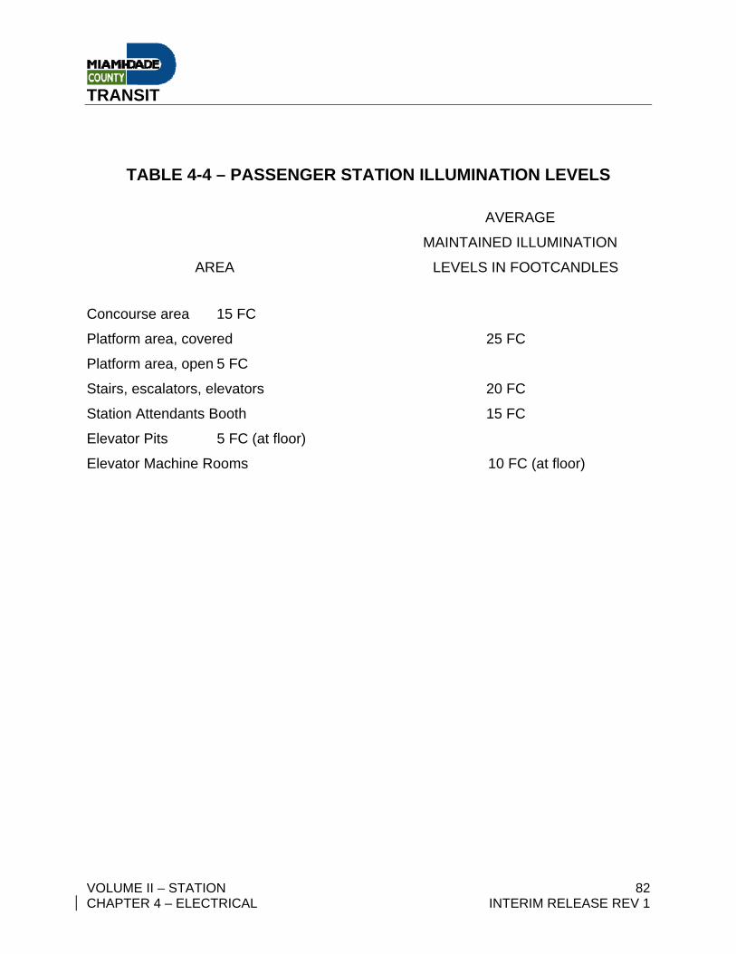
TRANSIT
VOLUME II – STATION 82 CHAPTER 4 – ELECTRICAL INTERIM RELEASE REV 1
TABLE 4-4 – PASSENGER STATION ILLUMINATION LEVELS
AVERAGE
MAINTAINED ILLUMINATION
AREA LEVELS IN FOOTCANDLES
Concourse area 15 FC
Platform area, covered 25 FC
Platform area, open 5 FC
Stairs, escalators, elevators 20 FC
Station Attendants Booth 15 FC
Elevator Pits 5 FC (at floor)
Elevator Machine Rooms 10 FC (at floor)
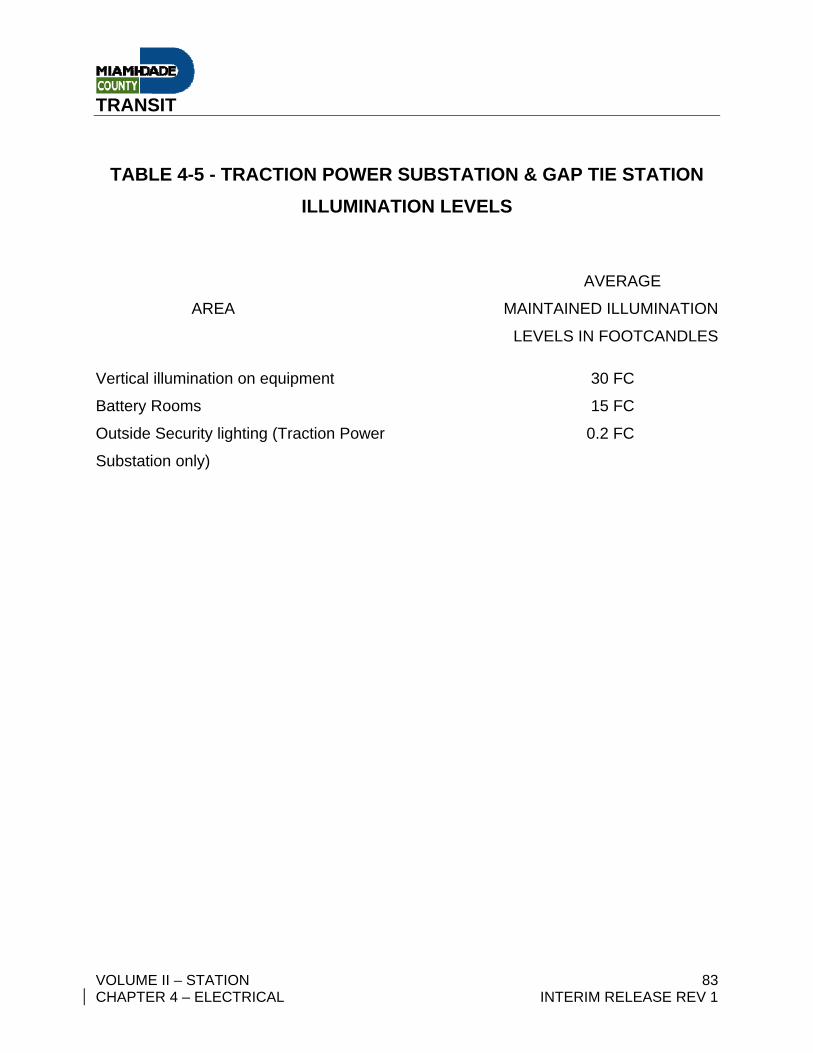
TRANSIT
VOLUME II – STATION 83 CHAPTER 4 – ELECTRICAL INTERIM RELEASE REV 1
TABLE 4-5 - TRACTION POWER SUBSTATION & GAP TIE STATION ILLUMINATION LEVELS
AVERAGE
AREA MAINTAINED ILLUMINATION
LEVELS IN FOOTCANDLES
Vertical illumination on equipment 30 FC
Battery Rooms 15 FC
Outside Security lighting (Traction Power 0.2 FC
Substation only)
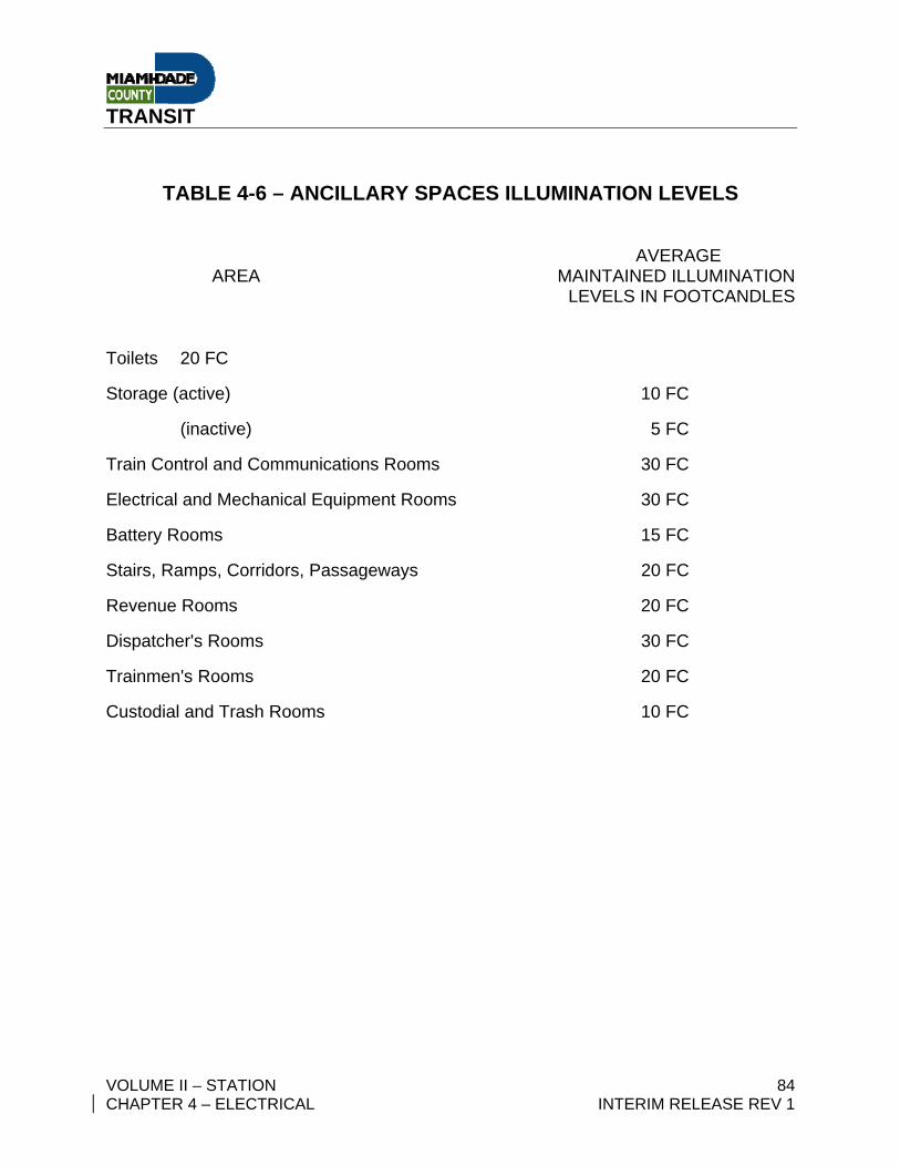
TRANSIT
VOLUME II – STATION 84 CHAPTER 4 – ELECTRICAL INTERIM RELEASE REV 1
TABLE 4-6 – ANCILLARY SPACES ILLUMINATION LEVELS AVERAGE AREA MAINTAINED ILLUMINATION LEVELS IN FOOTCANDLES
Toilets 20 FC
Storage (active) 10 FC
(inactive) 5 FC
Train Control and Communications Rooms 30 FC
Electrical and Mechanical Equipment Rooms 30 FC
Battery Rooms 15 FC
Stairs, Ramps, Corridors, Passageways 20 FC
Revenue Rooms 20 FC
Dispatcher's Rooms 30 FC
Trainmen's Rooms 20 FC
Custodial and Trash Rooms 10 FC
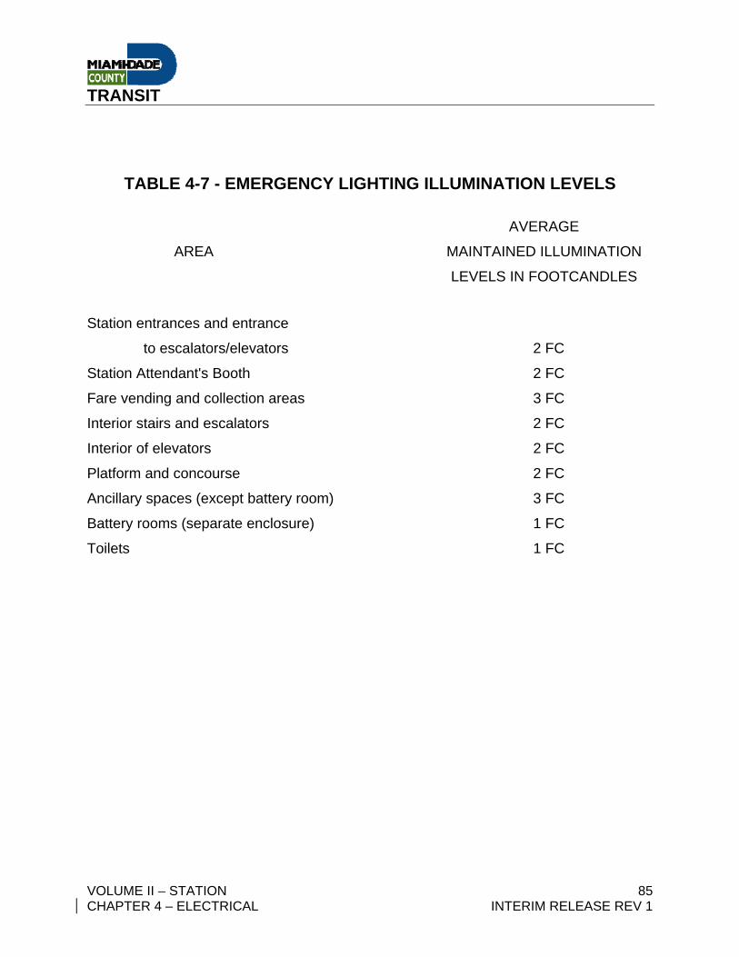
TRANSIT
VOLUME II – STATION 85 CHAPTER 4 – ELECTRICAL INTERIM RELEASE REV 1
TABLE 4-7 - EMERGENCY LIGHTING ILLUMINATION LEVELS
AVERAGE
AREA MAINTAINED ILLUMINATION
LEVELS IN FOOTCANDLES
Station entrances and entrance
to escalators/elevators 2 FC
Station Attendant's Booth 2 FC
Fare vending and collection areas 3 FC
Interior stairs and escalators 2 FC
Interior of elevators 2 FC
Platform and concourse 2 FC
Ancillary spaces (except battery room) 3 FC
Battery rooms (separate enclosure) 1 FC
Toilets 1 FC
TRANSIT
VOLUME II – STATION 86 CHAPTER 4 – ELECTRICAL INTERIM RELEASE REV 1
APPENDIX A (Reserved)
SYSTEMS-FACILITIES INTERFACE RACEWAY CRITERIA
GUIDE FOR DESIGNING WAYSIDE DUCT BANKS AND CONDUITS
Refer to: Volume III – Guideway Design, Chapter 4 – Guideway Electrical for Systems-Facilities Interface Raceway Criteria