Embed Size (px)
Citation preview
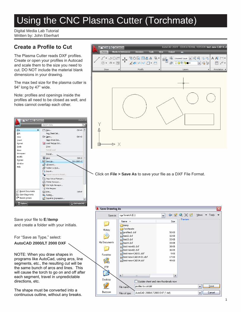
Using the CNC Plasma Cutter (Torchmate)Digital Media Lab TutorialWritten by: John Eberhart
The Plasma Cutter reads DXF profiles. Create or open your profiles in Autocad and scale them to the size you need to cut. DO NOT include the material blankdimensions in your drawing.
The max bed size for the plasma cutter is 94” long by 47” wide.
Note: profiles and openings inside the profiles all need to be closed as well, and holes cannot overlap each other.
Click on File > Save As to save your file as a DXF File Format.
Save your file to E:\temp and create a folder with your initials.
For “Save as Type,” select:AutoCAD 2000/LT 2000 DXF
Create a Profile to Cut
NOTE: When you draw shapes inprograms like AutoCad, using arcs, line segments, etc., the resulting cut will be the same bunch of arcs and lines. This will cause the torch to go on and off after each segment, travel in unpredictable directions, etc. The shape must be converted into a continuous outline, without any breaks.
1
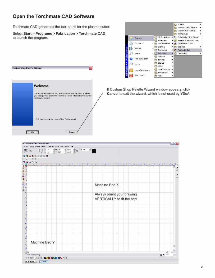
Open the Torchmate CAD Software
Torchmate CAD generates the tool paths for the plasma cutter.
Select Start > Programs > Fabrication > Torchmate CAD to launch the program.
If Custom Shop Palette Wizard window appears, click Cancel to exit the wizard, which is not used by YSoA.
Machine Bed X Always orient your drawing VERTICALLY to fit the bed.
Machine Bed Y
2
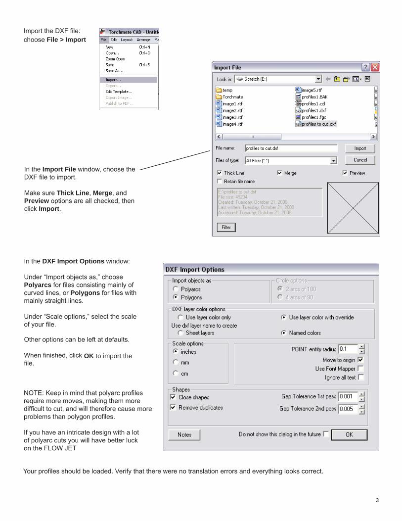
Import the DXF file:choose File > Import
In the Import File window, choose the DXF file to import.
Make sure Thick Line, Merge, and Preview options are all checked, then click Import.
In the DXF Import Options window:
Under “Import objects as,” choose Polyarcs for files consisting mainly of curved lines, or Polygons for files with mainly straight lines.
Under “Scale options,” select the scale of your file.
Other options can be left at defaults.
When finished, click OK to import the file.
NOTE: Keep in mind that polyarc profiles require more moves, making them moredifficult to cut, and will therefore cause more problems than polygon profiles. If you have an intricate design with a lotof polyarc cuts you will have better luckon the FLOW JET
Your profiles should be loaded. Verify that there were no translation errors and everything looks correct.
3
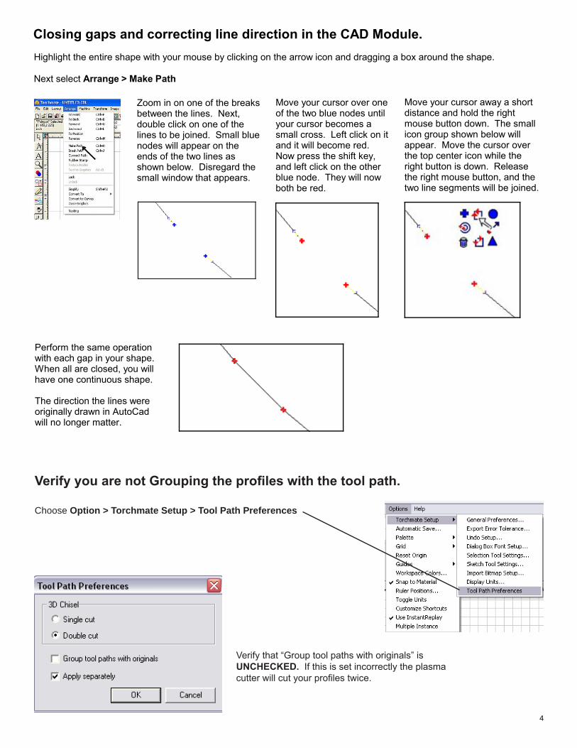
Verify you are not Grouping the profiles with the tool path.
Choose Option > Torchmate Setup > Tool Path Preferences
Verify that “Group tool paths with originals” is UNCHECKED. If this is set incorrectly the plasma cutter will cut your profiles twice.
Highlight the entire shape with your mouse by clicking on the arrow icon and dragging a box around the shape. Next select Arrange > Make Path
Closing gaps and correcting line direction in the CAD Module.
Zoom in on one of the breaks between the lines. Next, double click on one of the lines to be joined. Small blue nodes will appear on the ends of the two lines as shown below. Disregard the small window that appears.
Move your cursor over one of the two blue nodes until your cursor becomes a small cross. Left click on it and it will become red. Now press the shift key, and left click on the other blue node. They will now both be red.
Move your cursor away a short distance and hold the right mouse button down. The small icon group shown below will appear. Move the cursor over the top center icon while the right button is down. Release the right mouse button, and the two line segments will be joined.
Perform the same operation with each gap in your shape. When all are closed, you will have one continuous shape. The direction the lines were originally drawn in AutoCad will no longer matter.
4
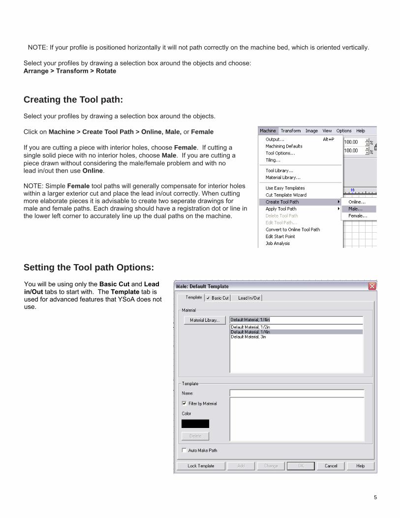
Creating the Tool path:Select your profiles by drawing a selection box around the objects.
Click on Machine > Create Tool Path > Online, Male, or Female
If you are cutting a piece with interior holes, choose Female. If cutting a single solid piece with no interior holes, choose Male. If you are cutting a piece drawn without considering the male/female problem and with nolead in/out then use Online. NOTE: Simple Female tool paths will generally compensate for interior holeswithin a larger exterior cut and place the lead in/out correctly. When cuttingmore elaborate pieces it is advisable to create two seperate drawings for male and female paths. Each drawing should have a registration dot or line inthe lower left corner to accurately line up the dual paths on the machine.
Setting the Tool path Options:
You will be using only the Basic Cut and Lead in/Out tabs to start with. The Template tab is used for advanced features that YSoA does not use.
NOTE: If your profile is positioned horizontally it will not path correctly on the machine bed, which is oriented vertically.
Select your profiles by drawing a selection box around the objects and choose: Arrange > Transform > Rotate
5
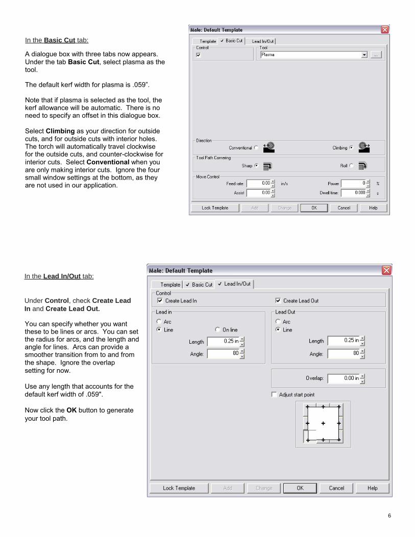
In the Basic Cut tab:
In the Lead In/Out tab:
Under Control, check Create Lead In and Create Lead Out.
A dialogue box with three tabs now appears. Under the tab Basic Cut, select plasma as the tool. The default kerf width for plasma is .059”. Note that if plasma is selected as the tool, the kerf allowance will be automatic. There is no need to specify an offset in this dialogue box. Select Climbing as your direction for outside cuts, and for outside cuts with interior holes. The torch will automatically travel clockwise for the outside cuts, and counter-clockwise for interior cuts. Select Conventional when you are only making interior cuts. Ignore the four small window settings at the bottom, as they are not used in our application.
You can specify whether you want these to be lines or arcs. You can set the radius for arcs, and the length and angle for lines. Arcs can provide a smoother transition from to and from the shape. Ignore the overlap setting for now. Use any length that accounts for thedefault kerf width of .059". Now click the OK button to generateyour tool path.
6
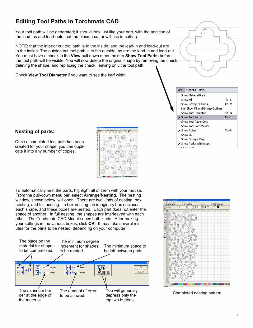
Editing Tool Paths in Torchmate CAD Your tool path will be generated; it should look just like your part, with the addition of the lead-ins and lead-outs that the plasma cutter will use in cutting. NOTE: that the interior cut tool path is to the inside, and the lead-in and lead-out are to the inside. The outside cut tool path is to the outside, as are the lead-in and lead-out. You must have a check in the View pull down menu next to Show Tool Paths before the tool path will be visible. You will now delete the original shape by removing the check, deleting the shape, and replacing the check, leaving only the tool path. Check View Tool Diameter if you want to see the kerf width.
Nesting of parts: Once a completed tool path has been created for your shape, you can dupli-cate it into any number of copies.
Completed nesting pattern
To automatically nest the parts, highlight all of them with your mouse. From the pull-down menu bar, select Arrange/Nesting. The nesting window, shown below, will open. There are two kinds of nesting, box nesting, and full nesting. In box nesting, an imaginary box encloses each shape, and these boxes are nested. Each part does not enter the space of another. In full nesting, the shapes are interleaved with each other. The Torchmate CAD Module does both kinds. After making your settings in the various boxes, click OK. It may take several min-utes for the parts to be nested, depending on your computer.
The place on the material for shapes to be compressed.
The minimum degree increment for shapes to be rotated.
The minimum space to be left between parts.
The minimum bor-der at the edge of the material.
The amount of error to be allowed.
You will generally depress only the top two buttons.
7
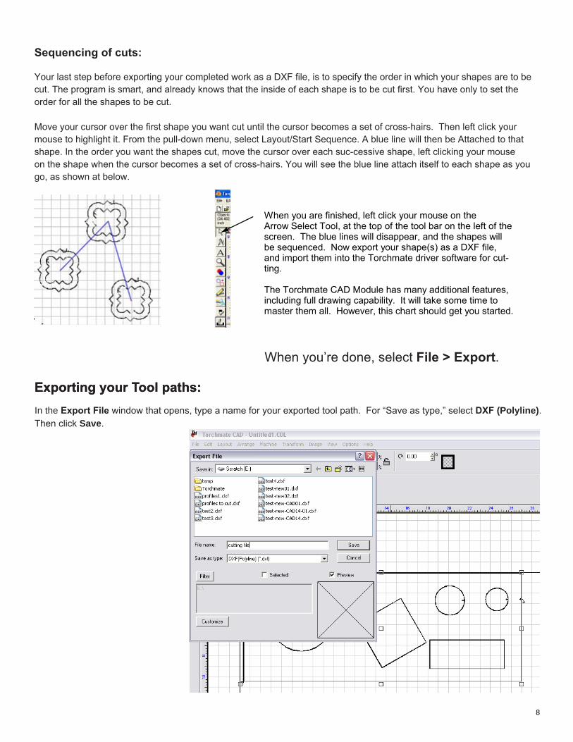
Exporting your Tool paths:In the Export File window that opens, type a name for your exported tool path. For “Save as type,” select DXF (Polyline). Then click Save.
When you’re done, select File > Export.
Exporting your Tool paths:
Sequencing of cuts: Your last step before exporting your completed work as a DXF file, is to specify the order in which your shapes are to be cut. The program is smart, and already knows that the inside of each shape is to be cut first. You have only to set the order for all the shapes to be cut. Move your cursor over the first shape you want cut until the cursor becomes a set of cross-hairs. Then left click your mouse to highlight it. From the pull-down menu, select Layout/Start Sequence. A blue line will then be Attached to that shape. In the order you want the shapes cut, move the cursor over each suc-cessive shape, left clicking your mouse on the shape when the cursor becomes a set of cross-hairs. You will see the blue line attach itself to each shape as you go, as shown at below.
When you are finished, left click your mouse on the Arrow Select Tool, at the top of the tool bar on the left of the screen. The blue lines will disappear, and the shapes will be sequenced. Now export your shape(s) as a DXF file, and import them into the Torchmate driver software for cut-ting. The Torchmate CAD Module has many additional features, including full drawing capability. It will take some time to master them all. However, this chart should get you started.
8
Cutting the Job: Starting the Machine, Loading a File, and Running the Machine
Place and Ground your Material
Place the material you wish to cut on the Torchmate bed.
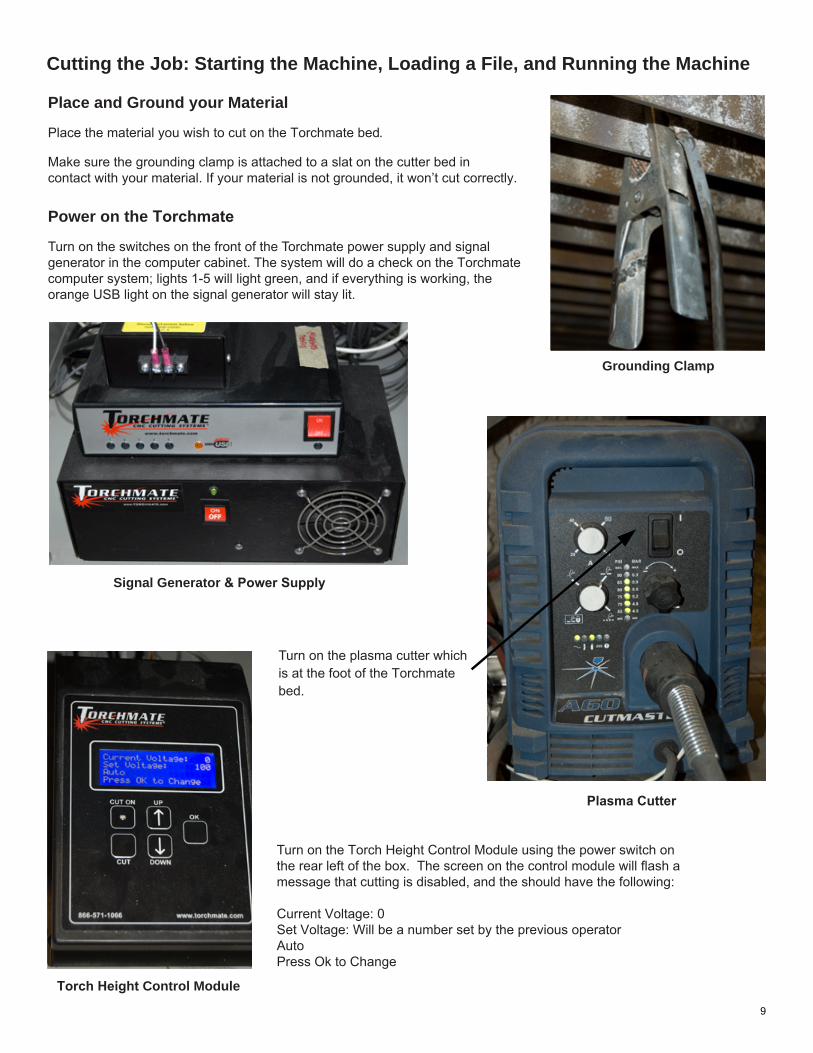
Make sure the grounding clamp is attached to a slat on the cutter bed in contact with your material. If your material is not grounded, it won’t cut correctly.
Power on the Torchmate
Turn on the switches on the front of the Torchmate power supply and signal generator in the computer cabinet. The system will do a check on the Torchmatecomputer system; lights 1-5 will light green, and if everything is working, the orange USB light on the signal generator will stay lit.
Turn on the Torch Height Control Module using the power switch on the rear left of the box. The screen on the control module will flash a message that cutting is disabled, and the should have the following: Current Voltage: 0Set Voltage: Will be a number set by the previous operatorAutoPress Ok to Change
Turn on the plasma cutter whichis at the foot of the Torchmatebed.
Grounding Clamp
Plasma Cutter
Signal Generator & Power Supply
Torch Height Control Module
9
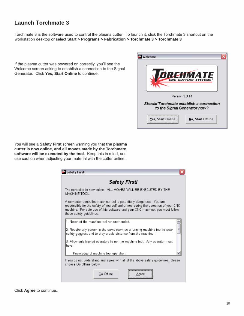
If the plasma cutter was powered on correctly, you’ll see the Welcome screen asking to establish a connection to the Signal Generator. Click Yes, Start Online to continue.
You will see a Safety First screen warning you that the plasma cutter is now online, and all moves made by the Torchmate software will be executed by the tool. Keep this in mind, and use caution when adjusting your material with the cutter online.
Click Agree to continue..
Launch Torchmate 3
Torchmate 3 is the software used to control the plasma cutter. To launch it, click the Torchmate 3 shortcut on the workstation desktop or select Start > Programs > Fabrication > Torchmate 3 > Torchmate 3
10
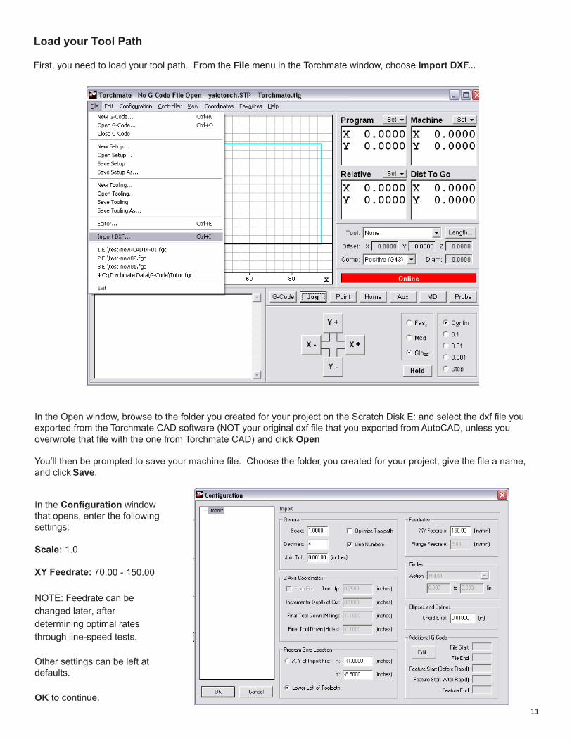
Load your Tool Path
First, you need to load your tool path. From the File menu in the Torchmate window, choose Import DXF...
In the Open window, browse to the folder you created for your project on the Scratch Disk E: and select the dxf file you exported from the Torchmate CAD software (NOT your original dxf file that you exported from AutoCAD, unless you overwrote that file with the one from Torchmate CAD) and click Open
. You’ll then be prompted to save your machine file. Choose the folder you created for your project, give the file a name, and click Save.
In the Configuration window that opens, enter the following settings:
Scale: 1.0
XY Feedrate: 70.00 - 150.00 NOTE: Feedrate can be changed later, after determining optimal rates through line-speed tests. Other settings can be left at defaults.
OK to continue.11
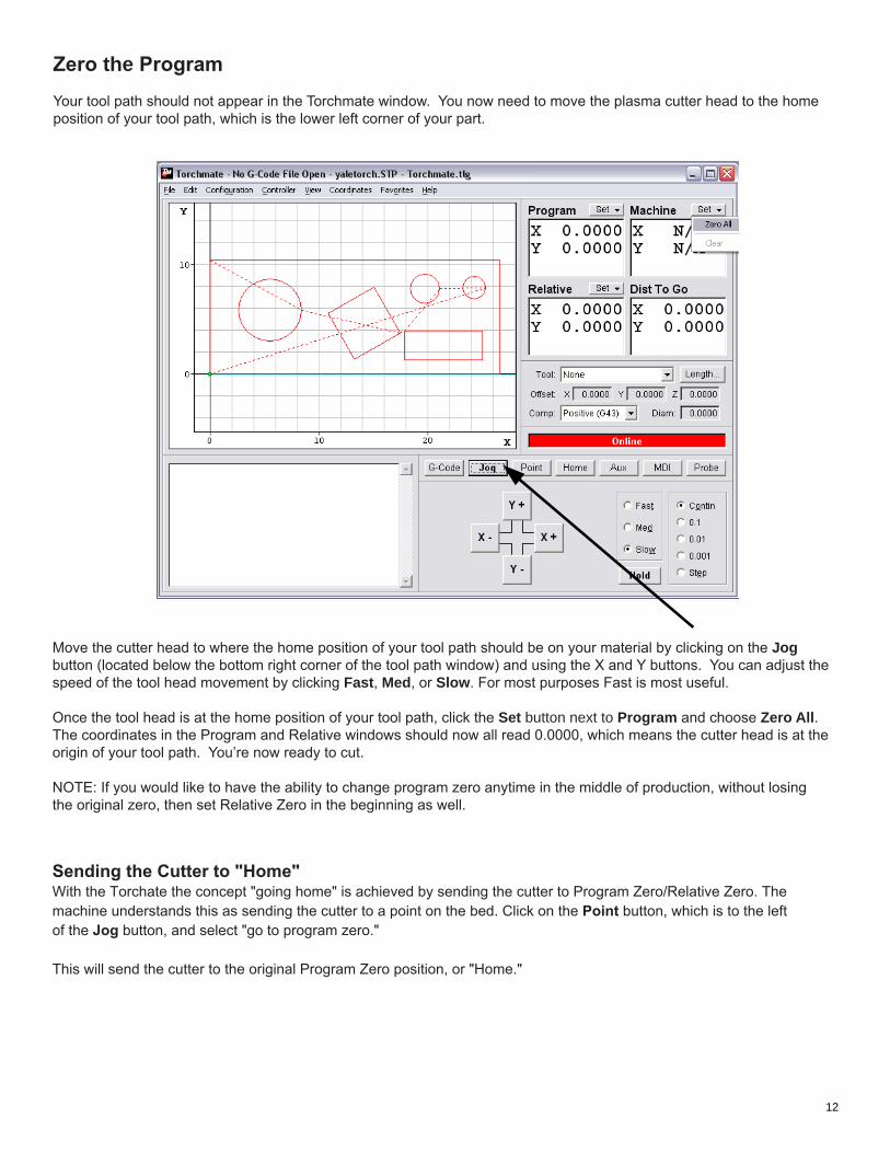
Zero the ProgramYour tool path should not appear in the Torchmate window. You now need to move the plasma cutter head to the home position of your tool path, which is the lower left corner of your part.
Move the cutter head to where the home position of your tool path should be on your material by clicking on the Jog button (located below the bottom right corner of the tool path window) and using the X and Y buttons. You can adjust the speed of the tool head movement by clicking Fast, Med, or Slow. For most purposes Fast is most useful.
Once the tool head is at the home position of your tool path, click the Set button next to Program and choose Zero All. The coordinates in the Program and Relative windows should now all read 0.0000, which means the cutter head is at the origin of your tool path. You’re now ready to cut. NOTE: If you would like to have the ability to change program zero anytime in the middle of production, without losingthe original zero, then set Relative Zero in the beginning as well.
Sending the Cutter to "Home"With the Torchate the concept "going home" is achieved by sending the cutter to Program Zero/Relative Zero. The machine understands this as sending the cutter to a point on the bed. Click on the Point button, which is to the left of the Jog button, and select "go to program zero." This will send the cutter to the original Program Zero position, or "Home."
12
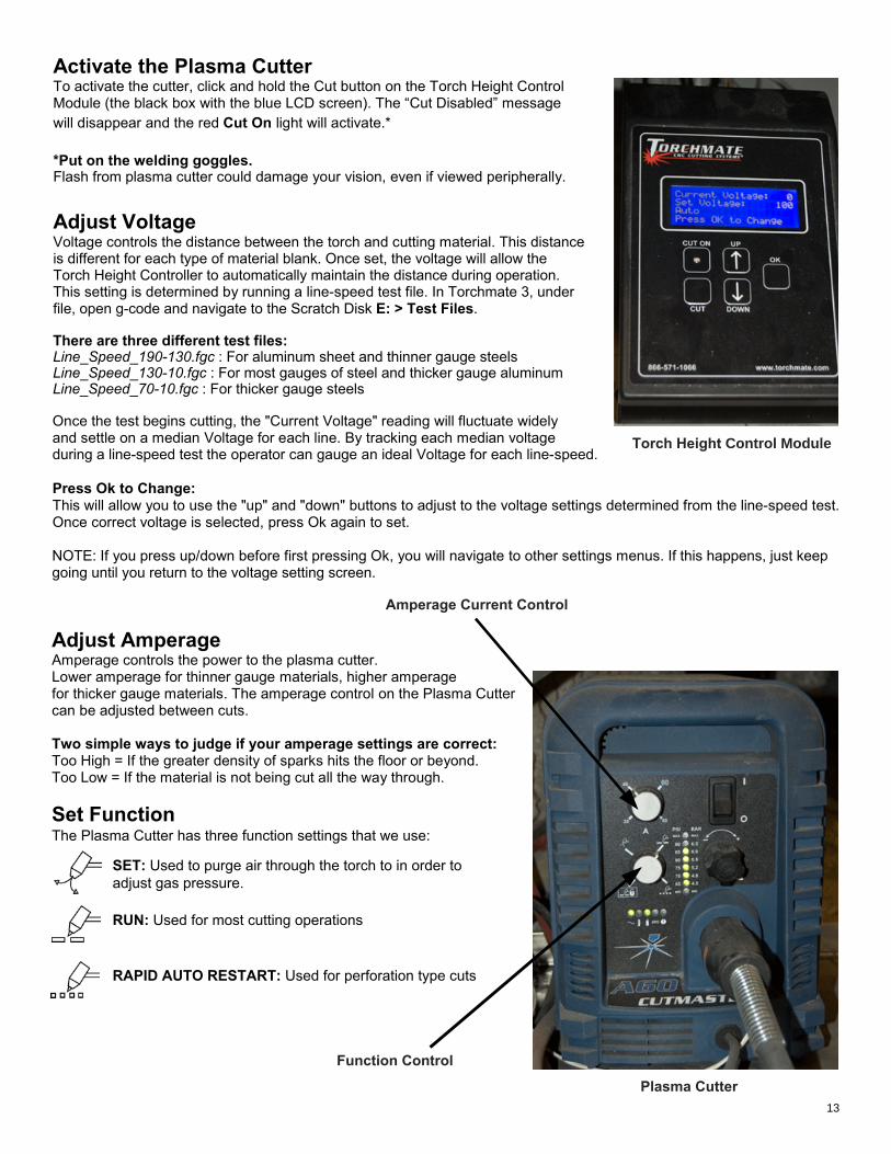
Activate the Plasma Cutter To activate the cutter, click and hold the Cut button on the Torch Height Control Module (the black box with the blue LCD screen). The “Cut Disabled” messagewill disappear and the red Cut On light will activate.* *Put on the welding goggles. Flash from plasma cutter could damage your vision, even if viewed peripherally. Adjust Voltage Voltage controls the distance between the torch and cutting material. This distanceis different for each type of material blank. Once set, the voltage will allow the Torch Height Controller to automatically maintain the distance during operation.This setting is determined by running a line-speed test file. In Torchmate 3, under file, open g-code and navigate to the Scratch Disk E: > Test Files. There are three different test files:Line_Speed_190-130.fgc : For aluminum sheet and thinner gauge steelsLine_Speed_130-10.fgc : For most gauges of steel and thicker gauge aluminumLine_Speed_70-10.fgc : For thicker gauge steels Once the test begins cutting, the "Current Voltage" reading will fluctuate widely and settle on a median Voltage for each line. By tracking each median voltage during a line-speed test the operator can gauge an ideal Voltage for each line-speed. Press Ok to Change: This will allow you to use the "up" and "down" buttons to adjust to the voltage settings determined from the line-speed test. Once correct voltage is selected, press Ok again to set. NOTE: If you press up/down before first pressing Ok, you will navigate to other settings menus. If this happens, just keep going until you return to the voltage setting screen. Adjust Amperage Amperage controls the power to the plasma cutter. Lower amperage for thinner gauge materials, higher amperage for thicker gauge materials. The amperage control on the Plasma Cutter can be adjusted between cuts. Two simple ways to judge if your amperage settings are correct: Too High = If the greater density of sparks hits the floor or beyond. Too Low = If the material is not being cut all the way through. Set FunctionThe Plasma Cutter has three function settings that we use: SET: Used to purge air through the torch to in order to adjust gas pressure. RUN: Used for most cutting operations RAPID AUTO RESTART: Used for perforation type cuts
Plasma Cutter
Amperage Current Control
Function Control
Torch Height Control Module
13
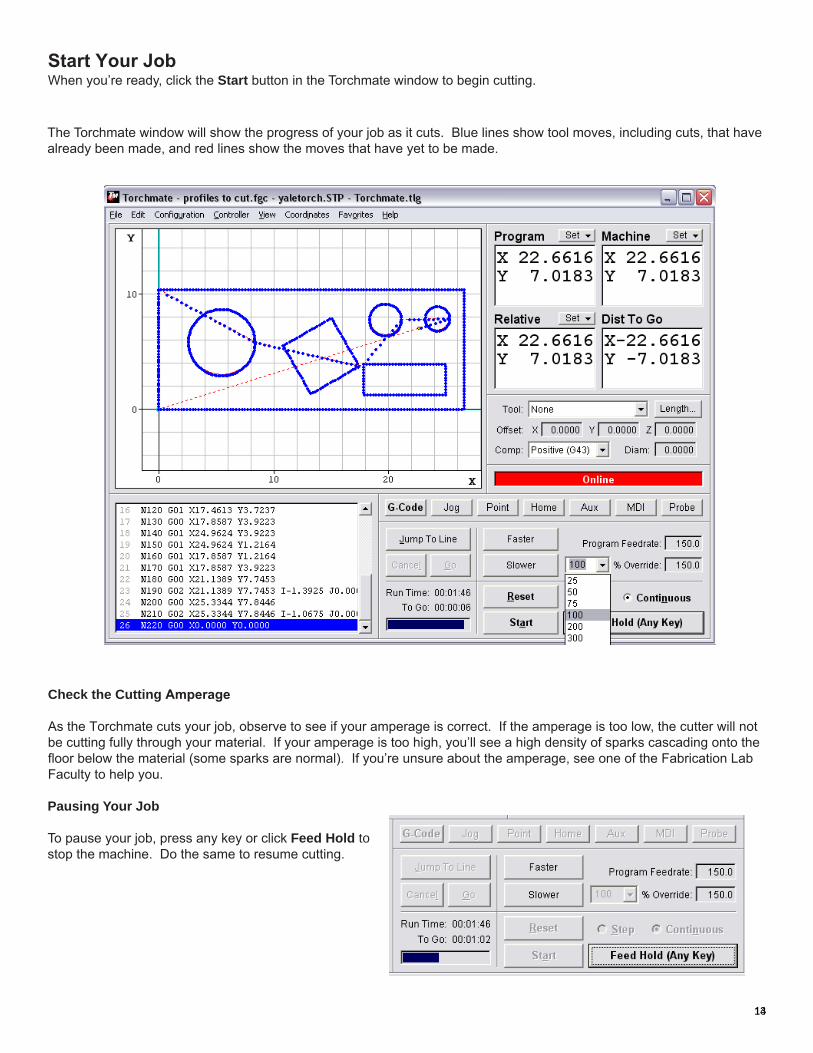
Start Your JobWhen you’re ready, click the Start button in the Torchmate window to begin cutting.
Check the Cutting Amperage
As the Torchmate cuts your job, observe to see if your amperage is correct. If the amperage is too low, the cutter will not be cutting fully through your material. If your amperage is too high, you’ll see a high density of sparks cascading onto the floor below the material (some sparks are normal). If you’re unsure about the amperage, see one of the Fabrication Lab Faculty to help you.
13
The Torchmate window will show the progress of your job as it cuts. Blue lines show tool moves, including cuts, that have already been made, and red lines show the moves that have yet to be made.
Pausing Your Job
To pause your job, press any key or click Feed Hold to stop the machine. Do the same to resume cutting.
14
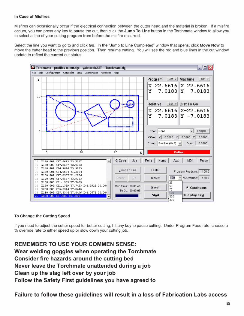
In Case of Misfires
Misfires can occasionally occur if the electrical connection between the cutter head and the material is broken. If a misfire occurs, you can press any key to pause the cut, then click the Jump To Line button in the Torchmate window to allow you to select a line of your cutting program from before the misfire occurred.
Select the line you want to go to and click Go. In the “Jump to Line Completed” window that opens, click Move Now to move the cutter head to the previous position. Then resume cutting. You will see the red and blue lines in the cut window update to reflect the current cut status.
To Change the Cutting Speed
If you need to adjust the cutter speed for better cutting, hit any key to pause cutting. Under Program Feed rate, choose a % override rate to either speed up or slow down your cutting job. REMEMBER TO USE YOUR COMMEN SENSE:Wear welding goggles when operating the Torchmate Consider fire hazards around the cutting bedNever leave the Torchmate unattended during a jobClean up the slag left over by your job Follow the Safety First guidelines you have agreed to Failure to follow these guidelines will result in a loss of Fabrication Labs access 1415