Embed Size (px)
Citation preview
9
INSTRUCTION MANUAL FOR PLASMA CUTTER
IMPORTANT: BEFORE STARTING THE EQUIPMENT, READ THE CONTENTS OF THIS MANUAL, WHICH MUST BE STORED IN A PLACE FAMILIAR TO ALL US-ERS FOR THE ENTIRE OPERATIVE LIFE-SPAN OF THE MACHINE.THIS EQUIPMENT MUST BE USED SOLELY FOR WELD-ING OPERATIONS.
1 SAFETY PRECAUTIONS
WELDING AND ARC CUTTING CAN BE HARM-FUL TO YOURSELF AND OTHERS. The user
must therefore be educated against the hazards, sum-marized below, deriving from welding operations. For more detailed information, order the manual code 3.300.758
NOISEThis machine does not directly produce noise ex-ceeding 80dB. The plasma cutting/welding pro-cedure may produce noise levels beyond said
limit; users must therefore implement all precautions re-quired by law.
ELECTRIC AND MAGNETIC FIELDS - May be dangerous.· Electric current following through any con-ductor causes localized Electric and Mag-netic Fields (EMF). Welding/cutting current creates EMF fields around cables and pow-er sources.
· The magnetic fields created by high currents may affect the operation of pacemakers. Wearers of vital electronic equipment (pacemakers) shall consult their physician be-fore beginning any arc welding, cutting, gouging or spot welding operations.· Exposure to EMF fields in welding/cutting may have other health effects which are now not known.· All operators should use the followingprocedures in or-der to minimize exposure to EMF fields from the welding/cutting circuit:- Route the electrode and work cables together - Secure
them with tape when possible.- Never coil the electrode/torch lead around your body.- Do not place your body between the electrode/torch
lead and work cables. If the electrode/torch lead cable is on your right side, the work cable should also be on your right side.
- Connect the work cable to the workpiece as close as possible to the area being welded/cut.
- Do not work next to welding/cutting power source.
EXPLOSIONS.· Do not weld in the vicinity of containers under pressure, or in the presence of explosive dust, gases or fumes. · All cylinders and pressure reg-
ulators used in welding operations should be handled with care.
ELECTROMAGNETIC COMPATIBILITYThis machine is manufactured in compliance with the in-structions contained in the standard IEC 60974-10 (CL. A), and must be used solely for professional purposes in an industrial environment. There may be potential difficulties in ensuring electromagnetic compatibility in non-industrial environments.
DISPOSAL OF ELECTRICAL AND ELECTRONIC EQUIPMENTDo not dispose of electrical equipment togeth-er with normal waste!In observance of European
Directive 2002/96/EC on Waste Electrical and Electron-ic Equipment and its implementation in accordance with national law, electrical equipment that has reached the end of its life must be collected separately and returned to an environmentally compatible recycling facility. As the owner of the equipment, you should get information on approved collection systems from our local representa-tive. By applying this European Directive you will improve the environment and human health!
IN CASE OF MALFUNCTIONS, REQUEST ASSISTANCE FROM QUALIFIED PERSONNEL.
1.1 WARNING LABEL
?
OFF
Gklaxm
zx, h
j x j
g b
nnsxm
ksksk
ghxnnm
zxkxsk
gasuwencm
c
tghsdhjsjksdjkxc
Ghgopglòdfòxlc òkvfàlxcvò l+dòvòùx
Sm,nxcv,mzx.c ierlòdfb-.èeì’,c mdlò
hsjkklasjlòsòlxc,òz
jhgfjksdhfjksdklcsmkldc
1 1.1 1.2 1.3
2 2.1 2.2 2.3
3 3.1 3.2 3.3
4 4.1 4.2 4.3
5 5.1
6 7
3098464
10
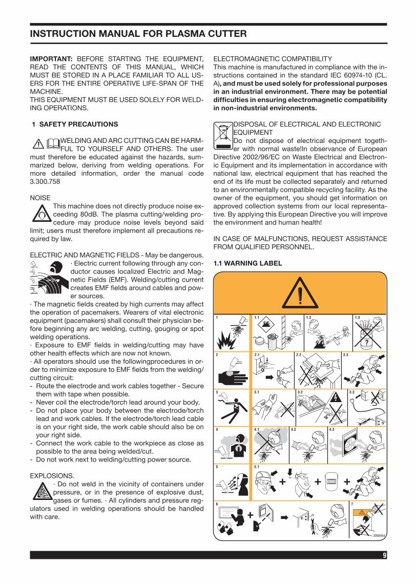
The following numbered text corresponds to the label numbered boxes.
1. Cutting sparks can cause explosion or fire. 1.1 Keep flammable materials away from cutting. 1.2 Cutting sparks can cause fires. Have a fire extin-
guisher nearby, and have a watchperson ready to use it.
1.3 Do not cut on drums or any closed container. 2. The plasma arc can cause injury and burns. 2.1 Turn off power before disassembling torch. 2.2 Do not grip material near cutting path.2.3 Wear complete body protection. 3. Electric shock from torch or wiring can kill. 3.1 Wear dry insulating gloves. Do not wear wet or dam-
aged gloves. 3.2 Protect yourself from electric shock by insulating
yourself from work and ground. 3.3 Disconnect input plug or power before working on
machine.4 Breathing cutting fumes can be hazardous to your
health. 4.1 Keep your head out of fumes. 4.2 Use forced ventilation or local exhaust to remove
fumes. 4.3 Use ventilating fan to remove fumes. 5 Arc rays may injure the eyes and burn the skin. Op-
erators should therefore shield their eyes with lens-es with a protection rating equal to or greater than DIN11 and adequately protect their face.
5.1 Wear hat and safety glasses. Use ear protection and button shirt collar. Use welding helmet with correct shade of filter. Wear complete body protection.
6 Become trained and read the instructions before working on the machine or cutting.
7 Do not remove or paint over (cover) the label.
2 GENERAL DESCRIPTION
This equipment is a direct current continuous power source designed for plasma arc cutting of electro-con-
ducting materials (metals and alloys). The plasma gas can be air or nitrogen.
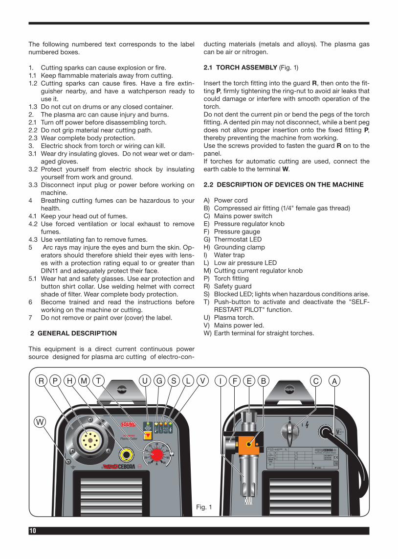
2.1 TORCH ASSEMBLY (Fig. 1)
Insert the torch fitting into the guard R, then onto the fit-ting P, firmly tightening the ring-nut to avoid air leaks that could damage or interfere with smooth operation of the torch.Do not dent the current pin or bend the pegs of the torch fitting. A dented pin may not disconnect, while a bent peg does not allow proper insertion onto the fixed fitting P, thereby preventing the machine from working.Use the screws provided to fasten the guard R on to the panel. If torches for automatic cutting are used, connect the earth cable to the terminal W.
2.2 DESCRIPTION OF DEVICES ON THE MACHINE A) Power cordB) Compressed air fitting (1/4" female gas thread)C) Mains power switchE) Pressure regulator knobF) Pressure gaugeG) Thermostat LEDH) Grounding clampI) Water trapL) Low air pressure LEDM) Cutting current regulator knobP) Torch fittingR) Safety guardS) Blocked LED; lights when hazardous conditions arise.T) Push-button to activate and deactivate the "SELF-
RESTART PILOT" function.U) Plasma torch.V) Mains power led.W) Earth terminal for straight torches.
W
Fig. 1
11
2.3 SAFETY DEVICES
This system comes equipped with the following safety devices:Overload cutout:
To avoid overloads. It is evidenced by the G led con-tinuosly on (see fig.1).
Pneumatic: Located on the torch inlet to prevent low air pres-sure. The LED L lights when tripped (see fig.1).
The blinking L led means that the pressure has temporar-ily gone below 3.2 ÷ 3.5 bar.Electrical:Located on the torch body, to prevent hazardous voltag-es from occurring on the torch when, swirl ring, electrode or nozzle holder are replaced;• Do not remove or short-circuit the safety devices.• Use only original spare parts.• Always replace any damaged parts of the machine
with original materials.• Do not run the machine without its housings. This
would be dangerous to the operator and anyone else in the work area, and would prevent the ma-chine from being cooled properly.
2.4 EXPLANATION OF TECHNICAL SPECIFICATIONS
This machine is manufactured according to the follow-ing international standards: IEC 60974.1 - IEC 60974.3 - IEC 60974.7 - IEC 60974.10 CL. A - IEC 61000-3-11 - IEC 61000-3-12 (61000-3-12 (see note 2).N°. Serial number. Must be indicated on any type of request re-
garding the device. Three-phase static transformer-rectifier fre-
quency converter. Downslope.
Suitable for plasma cutting.torch type Type of torch that may be used with this ma-
chine to form a safe system.U0. Secondary open-circuit voltage. X. Duty cycle percentage. The duty cycle expresses the percentage
of 10 minutes during which the welding ma-chine may run at a certain current I2 and voltage U2 without overheating.
I2. Cutting current. Art. 359: 60A @ 208/220/230/400/440V Art. 361: a) 100A @ 400/440V b) 80A @ 208/220/230VU2 Secondary conventional voltage with weld-
ing current I2 This voltage depends on the distance between the contact tip and the workpiece.
If this distance increases, the cutting voltage also increases and the duty cycle X% may decrease.
U1. Rated supply voltage for 208/220/230V - 400/440V with automatic voltage change.
3~ 50/60Hz 50- or 60-Hz three-phase power supply
I1 Max Max. absorbed current at the correspond-ing current I2 and voltage U2.
I1 eff This is the maximum value of the actual cur-rent absorbed, considering the duty cycle.
This value usually corresponds to the capa-city of the fuse (delayed type) to be used as a protection for the equipment.
IP23 S. Protection rating for the housing. Grade 3 as the second digit means that this
equipment may be stored, but it is not suit-able for use outdoors in the rain, unless it is protected.
S Suitable for use in high-risk environments.
NOTE:1- The machine has also been designed for use in envi-
ronments with a pollution rating of 1. (See IEC 60664).2- This equipment complies with IEC 61000-3-12 provid-
ed that the maximum permissible system impedance Zmax is less than or equal to 0,146 (Art. 359)-0,088 (Art. 361) at the interface point between the user's supply and the public system. It is the responsibility of the installer or user of the equipment to ensure, by consultation with the distribution network operator if necessary, that the equipment is connected only to a supply with maximum permissible system impedance Zmax less than or equal to 0,146 (Art. 359)-0,088 (Art. 361).
2.5 START-UP
The machine must be installed by qualified person-nel. All connections must be made in compliance with current safety standards and full observance of safety regulations (see CEI 26-23 - IEC TS 62081).Connect the air supply to the fitting B. If the air supply comes from a pressure regulator of a compressor or centralized system, the regulator must be set to an output pressure of no more than 8 bar (0.8 Mpa). If the air supply comes from a compressed air cylinder, the cylinder must be equipped with a pressure regula-tor. Never connect a compressed air cylinder directly to the regulator on the machine! The pressure could exceed the capacity of the regulator, which might ex-plode!Connect the power cord A: the yellow-green cable wire must be connected to an efficient grounding socket on the system. The remaining wires must be connected to the power supply line by means of a switch placed as close as possible to the cutting area, to allow it to be shut off quickly in case of emergency.The capacity of the cut-out switch or fuses installed in series with the switch must be equal to the current I1eff. absorbed by the machine.The absorbed current I1eff. may be determined by read-ing the technical specifications shown on the machine under the available supply voltage U1.Any extension cords must be sized appropriately for the absorbed current I1max.
12
3 USE
Make sure the trigger has not been pressed.Turn the machine on using the switch C. The warning lamp V will light to indicate that the machine is on.By pressing for an instant the welding torch button com-pressed air flow is opened. Under this condition set the pressure shown by the pressure gauge F, at 5 bar (0.5 MPa) for 6 m long torches and 0.55 bar (0.55 MPa) for 12 m long torches by means of the reducer knob E, and then lock the knob by pushing it down.Connect the grounding clamp to the workpiece.The cutting circuit must not be deliberately placed in di-rect or indirect contact with the protective wire except in the workpiece.If the workpiece is deliberately grounded using the pro-tective conductor, the connection must be as direct as possible and use a wire of at least the same size as the cutting current return wire, and connected to the work-piece at the same point as the return wire using the re-turn wire clamp or a second grounding clamp placed in the immediate vicinity. Every precaution must be taken to avoid stray currents.
3.1 CUTTING (“CUT” OPERATING MODE)
Use the knob M to select the cutting current.Cebora CP101 welding torch: with nozzle ø 1.2 and 45 to 60 A currents use the two faces spacer Art. 1404.Cebora CP161 welding torch: With a 20 to 40A cutting current and a 0.8 mm diameter nozzle a cut can be made by placing the noz-zle directly on the workpiece (drag cut).For currents higher than 40A a spring spacer or a 2-end spacer must be used to avoid to put into direct contact the nozzle or the nozzle protection with the workpiece to be cut.With the welding torch in automatic mode, keep a dis-tance of approximately 4mm between the nozzle protec-tion and the workpiece, as indicated in the cutting tables.
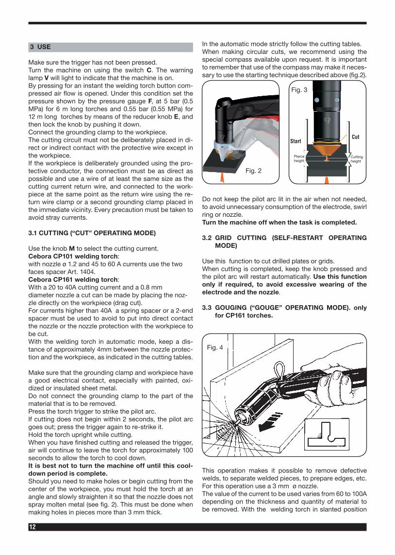
Make sure that the grounding clamp and workpiece have a good electrical contact, especially with painted, oxi-dized or insulated sheet metal.Do not connect the grounding clamp to the part of the material that is to be removed.Press the torch trigger to strike the pilot arc.If cutting does not begin within 2 seconds, the pilot arc goes out; press the trigger again to re-strike it. Hold the torch upright while cutting.When you have finished cutting and released the trigger, air will continue to leave the torch for approximately 100 seconds to allow the torch to cool down. It is best not to turn the machine off until this cool-down period is complete.Should you need to make holes or begin cutting from the center of the workpiece, you must hold the torch at an angle and slowly straighten it so that the nozzle does not spray molten metal (see fig. 2). This must be done when making holes in pieces more than 3 mm thick.
In the automatic mode strictly follow the cutting tables.When making circular cuts, we recommend using the special compass available upon request. It is important to remember that use of the compass may make it neces-sary to use the starting technique described above (fig.2).
Fig. 2
Fig. 3
Do not keep the pilot arc lit in the air when not needed, to avoid unnecessary consumption of the electrode, swirl ring or nozzle.Turn the machine off when the task is completed.
3.2 GRID CUTTING (SELF-RESTART OPERATING MODE)
Use this function to cut drilled plates or grids. When cutting is completed, keep the knob pressed and the pilot arc will restart automatically. Use this function only if required, to avoid excessive wearing of the electrode and the nozzle.
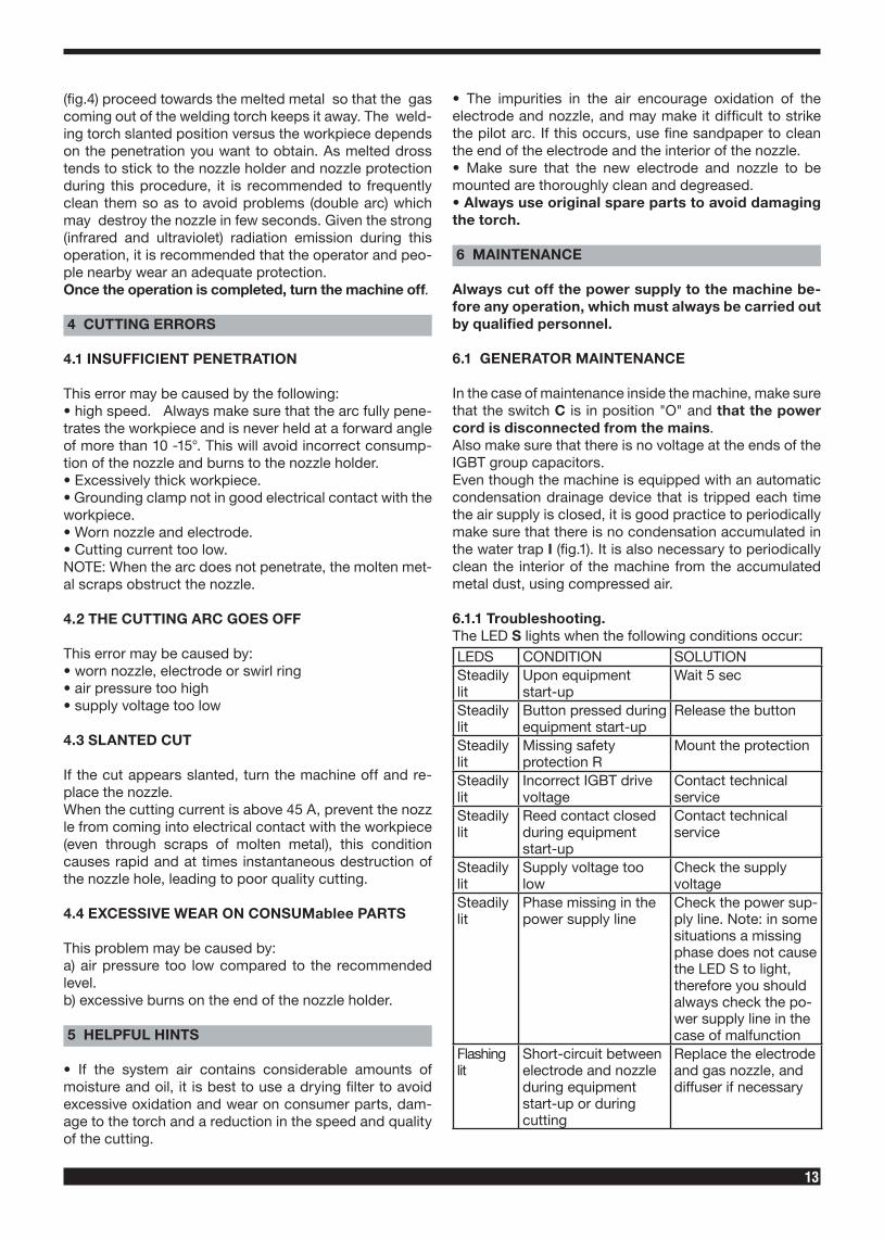
3.3 GOUGING (“GOUGE” OPERATING MODE). only for CP161 torches.
Fig. 4
This operation makes it possible to remove defective welds, to separate welded pieces, to prepare edges, etc. For this operation use a 3 mm ø nozzle. The value of the current to be used varies from 60 to 100A depending on the thickness and quantity of material to be removed. With the welding torch in slanted position
13
(fig.4) proceed towards the melted metal so that the gas coming out of the welding torch keeps it away. The weld-ing torch slanted position versus the workpiece depends on the penetration you want to obtain. As melted dross tends to stick to the nozzle holder and nozzle protection during this procedure, it is recommended to frequently clean them so as to avoid problems (double arc) which may destroy the nozzle in few seconds. Given the strong (infrared and ultraviolet) radiation emission during this operation, it is recommended that the operator and peo-ple nearby wear an adequate protection. Once the operation is completed, turn the machine off.
4 CUTTING ERRORS
4.1 INSUFFICIENT PENETRATION
This error may be caused by the following:• high speed. Always make sure that the arc fully pene-trates the workpiece and is never held at a forward angle of more than 10 -15°. This will avoid incorrect consump-tion of the nozzle and burns to the nozzle holder.• Excessively thick workpiece.• Grounding clamp not in good electrical contact with the workpiece.• Worn nozzle and electrode.• Cutting current too low.NOTE: When the arc does not penetrate, the molten met-al scraps obstruct the nozzle.
4.2 THE CUTTING ARC GOES OFF
This error may be caused by:• worn nozzle, electrode or swirl ring• air pressure too high• supply voltage too low
4.3 SLANTED CUT
If the cut appears slanted, turn the machine off and re-place the nozzle.When the cutting current is above 45 A, prevent the nozzle from coming into electrical contact with the workpiece (even through scraps of molten metal), this condition causes rapid and at times instantaneous destruction of the nozzle hole, leading to poor quality cutting.
4.4 EXCESSIVE WEAR ON CONSUMablee PARTS
This problem may be caused by:a) air pressure too low compared to the recommended level.b) excessive burns on the end of the nozzle holder.
5 HELPFUL HINTS
• If the system air contains considerable amounts of moisture and oil, it is best to use a drying filter to avoid excessive oxidation and wear on consumer parts, dam-age to the torch and a reduction in the speed and quality of the cutting.
• The impurities in the air encourage oxidation of the electrode and nozzle, and may make it difficult to strike the pilot arc. If this occurs, use fine sandpaper to clean the end of the electrode and the interior of the nozzle.• Make sure that the new electrode and nozzle to be mounted are thoroughly clean and degreased.• Always use original spare parts to avoid damaging the torch.
6 MAINTENANCE
Always cut off the power supply to the machine be-fore any operation, which must always be carried out by qualified personnel.
6.1 GENERATOR MAINTENANCE
In the case of maintenance inside the machine, make sure that the switch C is in position "O" and that the power cord is disconnected from the mains.Also make sure that there is no voltage at the ends of the IGBT group capacitors. Even though the machine is equipped with an automatic condensation drainage device that is tripped each time the air supply is closed, it is good practice to periodically make sure that there is no condensation accumulated in the water trap I (fig.1). It is also necessary to periodically clean the interior of the machine from the accumulated metal dust, using compressed air.
6.1.1 Troubleshooting.The LED S lights when the following conditions occur:LEDS CONDITION SOLUTIONSteadily lit
Upon equipment start-up
Wait 5 sec
Steadily lit
Button pressed during equipment start-up
Release the button
Steadily lit
Missing safety protection R
Mount the protection
Steadily lit
Incorrect IGBT drive voltage
Contact technical service
Steadily lit
Reed contact closed during equipment start-up
Contact technical service
Steadily lit
Supply voltage too low
Check the supply voltage
Steadily lit
Phase missing in the power supply line
Check the power sup-ply line. Note: in some situations a missing phase does not cause the LED S to light, therefore you should always check the po-wer supply line in the case of malfunction
Flashing lit
Short-circuit between electrode and nozzle during equipment start-up or during cutting
Replace the electrode and gas nozzle, and diffuser if necessary
14
6.2 TORCH MAINTENANCE
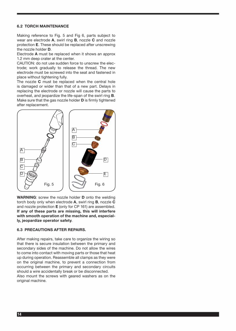
Making reference to Fig. 5 and Fig 6, parts subject to wear are electrode A, swirl ring B, nozzle C and nozzle protection E. These should be replaced after unscrewing the nozzle holder D.Electrode A must be replaced when it shows an approx 1.2 mm deep crater at the center. CAUTION: do not use sudden force to unscrew the elec-trode; work gradually to release the thread. The new electrode must be screwed into the seat and fastened in place without tightening fully.The nozzle C must be replaced when the central hole is damaged or wider than that of a new part. Delays in replacing the electrode or nozzle will cause the parts to overheat, and jeopardize the life-span of the swirl ring B. Make sure that the gas nozzle holder D is firmly tightened after replacement.
Fig. 5 Fig. 6
A
A
B
B
D
D
E
C
C
WARNING: screw the nozzle holder D onto the welding torch body only when electrode A, swirl ring B, nozzle C and nozzle protection E (only for CP 161) are assembled. If any of these parts are missing, this will interfere with smooth operation of the machine and, especial-ly, jeopardize operator safety.
6.3 PRECAUTIONS AFTER REPAIRS.
After making repairs, take care to organize the wiring so that there is secure insulation between the primary and secondary sides of the machine. Do not allow the wires to come into contact with moving parts or those that heat up during operation. Reassemble all clamps as they were on the original machine, to prevent a connection from occurring between the primary and secondary circuits should a wire accidentally break or be disconnected.Also mount the screws with geared washers as on the original machine.
73
QUESTA PARTE È DESTINATA ESCLUSIVAMENTE AL PERSONALE QUALIFICATO.
THIS PART IS INTENDED SOLELY FOR QUALIFIED PERSONNEL.
DIESER TEIL IST AUSSCHLIESSLICH FÜR DAS FACHPERSONAL BESTIMMT.
CETTE PARTIE EST DESTINEE EXCLUSIVEMENT AU PERSONNEL QUALIFIE.
ESTA PARTE ESTÁ DESTINADA EXCLUSIVAMENTE AL PERSONAL CUALIFICADO.
ESTA PARTE È DEDICADA EXCLUSIVAMENTE AO PESSOAL QUALIFICADO.
TÄMÄ OSA ON TARKOITETTU AINOASTAAN AMMATTITAITOISELLE HENKILÖKUNNALLE.
DETTE AFSNIT HENVENDER SIG UDELUKKENDE TIL KVALIFICERET PERSONALE.
DIT DEEL IS UITSLUITEND BESTEMD VOOR BEVOEGD PERSONEEL.
DENNA DEL ÄR ENDAST AVSEDD FÖR KVALIFICERAD PERSONAL.
AUTO V TO TMH VMA PROORI VZETAI APOKLEISTIKAV GIA TO EIDIKEUME VNO PROSWPIKO. V
74
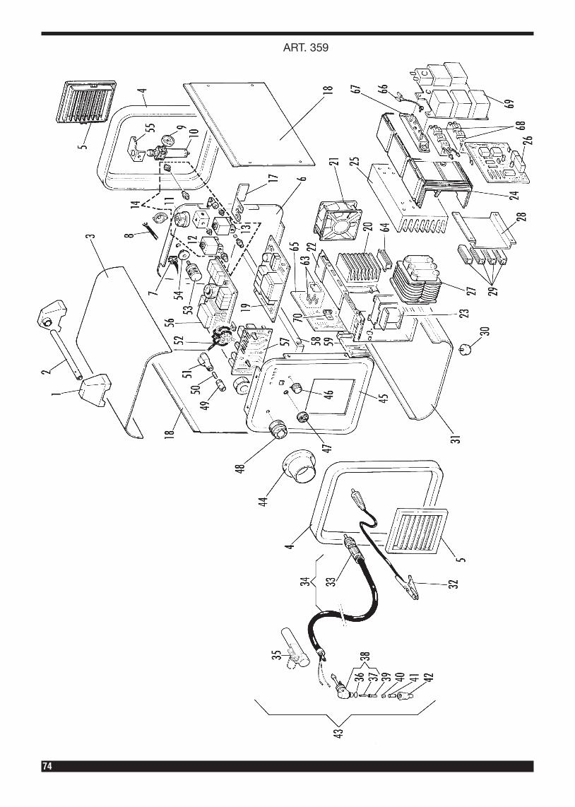
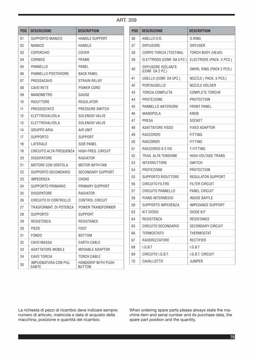
ART. 359
75
La richiesta di pezzi di ricambio deve indicare sempre: numero di articolo, matricola e data di acquisto della macchina, posizione e quantità del ricambio.
When ordering spare parts please always state the ma-chine item and serial number and its purchase data, the spare part position and the quantity.
POS DESCRIZIONE DESCRIPTION
01 SUPPORTO MANICO HANDLE SUPPORT
02 MANICO HANDLE
03 COPERCHIO COVER
04 CORNICE FRAME
05 PANNELLO PANEL
06 PANNELLO POSTERIORE BACK PANEL
07 PRESSACAVO STRAIN RELIEF
08 CAVO RETE POWER CORD
09 MANOMETRO GAUGE
10 RIDUTTORE REGULATOR
11 PRESSOSTATO PRESSURE SWITCH
12 ELETTROVALVOLA SOLENOID VALVE
13 ELETTROVALVOLA SOLENOID VALVE
14 GRUPPO ARIA AIR UNIT
17 SUPPORTO SUPPORT
18 LATERALE SIDE PANEL
19 CIRCUITO ALTA FREQUENZA HIGH-FREQ. CIRCUIT
20 DISSIPATORE RADIATOR
21 MOTORE CON VENTOLA MOTOR WITH FAN
22 SUPPORTO SECONDARIO SECONDARY SUPPORT
23 IMPEDENZA CHOKE
24 SUPPORTO PRIMARIO PRIMARY SUPPORT
25 DISSIPATORE RADIATOR
26 CIRCUITO DI CONTROLLO CONTROL CIRCUIT
27 TRASFORMAT. DI POTENZA POWER TRANSFORMER
28 SUPPORTO SUPPORT
29 RESISTENZA RESISTANCE
30 PIEDE FOOT
31 FONDO BOTTOM
32 CAVO MASSA EARTH CABLE
33 ADATTATORE MOBILE MOVABLE ADAPTOR
34 CAVO TORCIA TORCH CABLE
35 IMPUGNATURA CON PUL-SANTE
HANDGRIP WITH PUSH BUTTON
POS DESCRIZIONE DESCRIPTION
36 ANELLO O.R. O.RING
37 DIFFUSORE DIFFUSER
38 CORPO TORCIA (TESTINA) TORCH BODY (HEAD)
39 ELETTRODO (CONF. DA 5 PZ.) ELECTRODE (PACK. 5 PCS.)
40 DIFFUSORE ISOLANTE (CONF. DA 2 PZ.) SWIRL RING (PACK 2 PCS.)
41 UGELLO (CONF. DA 5PZ.) NOZZLE ( PACK. 5 PCS.)
42 PORTAUGELLO NOZZLE HOLDER
43 TORCIA COMPLETA COMPLETE TORCHE
44 PROTEZIONE PROTECTION
45 PANNELLO ANTERIORE FRONT PANEL
46 MANOPOLA KNOB
47 PRESA SOCKET
48 ADATTATORE FISSO FIXED ADAPTOR
49 RACCORDO FITTING
50 RACCORDO FITTING
51 RACCORDO A 3 VIE T-FITTING
52 TRAS. ALTA TENSIONE HIGH-VOLTAGE TRANS
53 INTERRUTTORE SWITCH
54 PROTEZIONE PROTECTION
55 SUPPORTO RIDUTTORE REGULATOR SUPPORT
56 CIRCUITO FILTRO FILTER CIRCUIT
57 CIRCUITO PANNELLO PANEL CIRCUIT
58 PIANO INTERMEDIO INSIDE BAFFLE
59 SUPPORTO IMPEDENZA IMPEDANCE SUPPORT
63 KIT DIODO DIODE KIT
64 RESISTENZA RESISTANCE
65 CIRCUITO SECONDARIO SECONDARY CIRCUIT
66 TERMOSTATO THERMOSTAT
67 RADDRIZZATORE RECTIFIER
68 I.G.B.T I.G.B.T
69 CIRCUITO I.G.B.T. I.G.B.T. CIRCUIT
70 CAVALLOTTO JUMPER
ART. 359
76
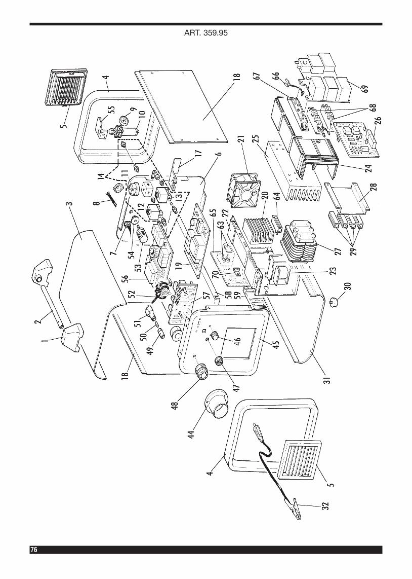
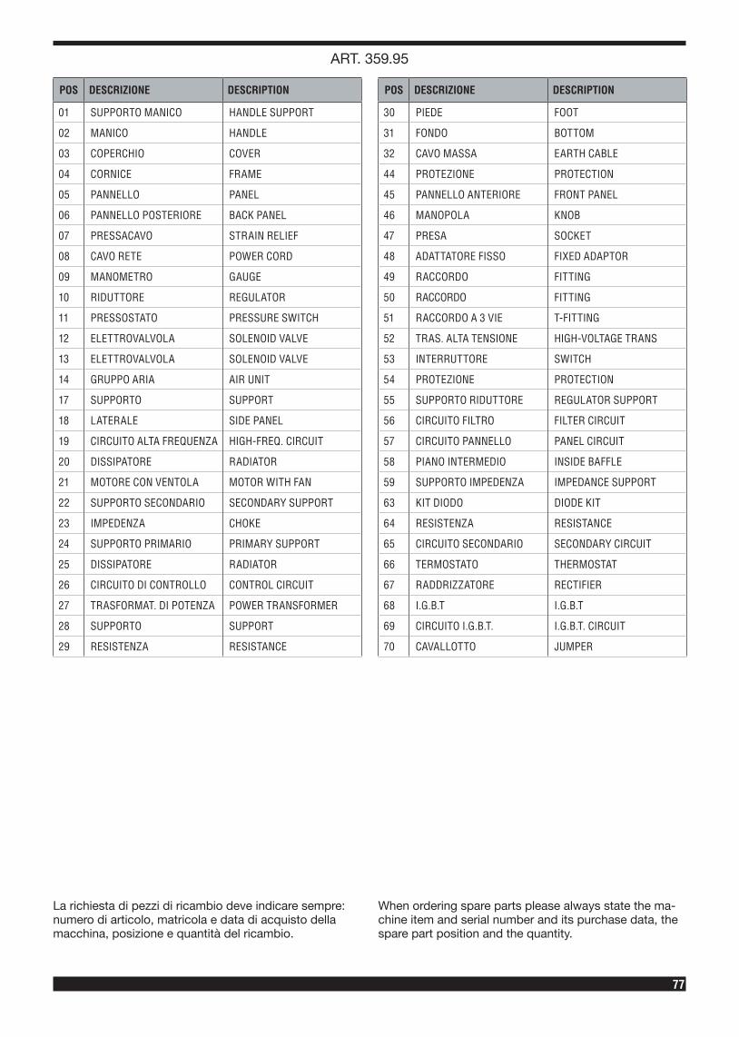
ART. 359.95
77
La richiesta di pezzi di ricambio deve indicare sempre: numero di articolo, matricola e data di acquisto della macchina, posizione e quantità del ricambio.
When ordering spare parts please always state the ma-chine item and serial number and its purchase data, the spare part position and the quantity.
POS DESCRIZIONE DESCRIPTION
01 SUPPORTO MANICO HANDLE SUPPORT
02 MANICO HANDLE
03 COPERCHIO COVER
04 CORNICE FRAME
05 PANNELLO PANEL
06 PANNELLO POSTERIORE BACK PANEL
07 PRESSACAVO STRAIN RELIEF
08 CAVO RETE POWER CORD
09 MANOMETRO GAUGE
10 RIDUTTORE REGULATOR
11 PRESSOSTATO PRESSURE SWITCH
12 ELETTROVALVOLA SOLENOID VALVE
13 ELETTROVALVOLA SOLENOID VALVE
14 GRUPPO ARIA AIR UNIT
17 SUPPORTO SUPPORT
18 LATERALE SIDE PANEL
19 CIRCUITO ALTA FREQUENZA HIGH-FREQ. CIRCUIT
20 DISSIPATORE RADIATOR
21 MOTORE CON VENTOLA MOTOR WITH FAN
22 SUPPORTO SECONDARIO SECONDARY SUPPORT
23 IMPEDENZA CHOKE
24 SUPPORTO PRIMARIO PRIMARY SUPPORT
25 DISSIPATORE RADIATOR
26 CIRCUITO DI CONTROLLO CONTROL CIRCUIT
27 TRASFORMAT. DI POTENZA POWER TRANSFORMER
28 SUPPORTO SUPPORT
29 RESISTENZA RESISTANCE
POS DESCRIZIONE DESCRIPTION
30 PIEDE FOOT
31 FONDO BOTTOM
32 CAVO MASSA EARTH CABLE
44 PROTEZIONE PROTECTION
45 PANNELLO ANTERIORE FRONT PANEL
46 MANOPOLA KNOB
47 PRESA SOCKET
48 ADATTATORE FISSO FIXED ADAPTOR
49 RACCORDO FITTING
50 RACCORDO FITTING
51 RACCORDO A 3 VIE T-FITTING
52 TRAS. ALTA TENSIONE HIGH-VOLTAGE TRANS
53 INTERRUTTORE SWITCH
54 PROTEZIONE PROTECTION
55 SUPPORTO RIDUTTORE REGULATOR SUPPORT
56 CIRCUITO FILTRO FILTER CIRCUIT
57 CIRCUITO PANNELLO PANEL CIRCUIT
58 PIANO INTERMEDIO INSIDE BAFFLE
59 SUPPORTO IMPEDENZA IMPEDANCE SUPPORT
63 KIT DIODO DIODE KIT
64 RESISTENZA RESISTANCE
65 CIRCUITO SECONDARIO SECONDARY CIRCUIT
66 TERMOSTATO THERMOSTAT
67 RADDRIZZATORE RECTIFIER
68 I.G.B.T I.G.B.T
69 CIRCUITO I.G.B.T. I.G.B.T. CIRCUIT
70 CAVALLOTTO JUMPER
ART. 359.95
78
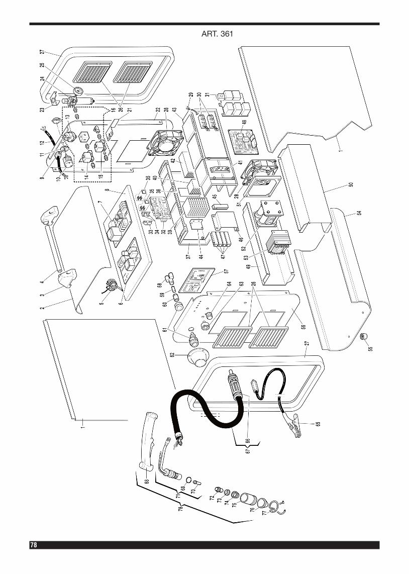
ART. 361

79
La richiesta di pezzi di ricambio deve indicare sempre: numero di articolo, matricola e data di acquisto della macchina, posizione e quantità del ricambio.
When ordering spare parts please always state the ma-chine item and serial number and its purchase data, the spare part position and the quantity.
POS DESCRIZIONE DESCRIPTION
01 LATERALE SIDE PANEL
02 COPERCHIO COVER
03 SUPPORTO MANICO HANDLE SUPPORT
04 MANICO HANDLE
05 TRAS. ALTA TENSIONE HIGH-VOLTAGE TRANS.
06 CORCUITO ALTA FREQUENZA HIGH-FREQ. CIRCUIT
07 CIRCUITO FILTRO FILTER CIRCUIT
08 PIANO INTERMEDIO INSIDE BAFFLE
09 PRESSACAVO STRAIN RELIEF
10 INTERRUTTORE REGULATOR
11 PROTEZIONE PROTECTION
12 CAVO RETE POWER CORD
13 PRESSOSTATO PRESSURE SWITCH
14 ELETTROVALVOLA SOLENOID VALVE
15 ELETTROVALVOLA SOLENOID VALVE
16 GRUPPO ARIA AIR UNIT
21 SUPPORTO SUPPORT
22 PANNELLO POSTERIORE BACK PANEL
23 SUPPORTO RIDUTTORE REGULATOR SUPPORT
24 RIDUTTORE REGULATOR
25 MANOMETRO GAUGE
26 PANNELLO PANEL
27 CORNICE FRAME
28 MOTORE CON VENTOLA MOTOR WITH FAN
29 TERMOSTATO THERMOSTAT
30 I.G.B.T. I.G.B.T.
31 CIRCUITO I.G.B.T. I.G.B.T. CIRCUIT
32 CIRCUITO SECONDARIO SECONDARY CIRCUIT
33 CAVALLOTTO POSITIVO POSITIVE JUMPER
34 CAVALLOTTO NEGATIVO NEGATIVE JUMPER
35 KIT DIODI DIODE KIT
37 SUPPORTO SECONDARIO SECONDARY SUPPORT
38 ISOLAMENTO INSULATION
39 DISSIPATORE RADIATOR
40 DISSIPATORE RADIATOR
41 RADDRIZZATORE RECTIFIER
42 DISSIPATORE RADIATOR
43 SUPPORTO PRIMARIO PRIMARY SUPPORT
POS DESCRIZIONE DESCRIPTION
44 SUPPORTO RESISTENZA RESISTANCE SUPPORT
45 RESISTENZA RESISTANCE
46 SUPPORTO RESISTENZA RESISTANCE SUPPORT
47 RESISTENZA RESISTANCE
48 CIRCUITO DI CONTROLLO CONTROL CIRCUIT
49 SUPPORTO CENTRALE SX. LEFT CENTRAL SUPPORT
50 SUPPORTO CENTRALE DX. RIGHT CENTRAL SUPPORT
51 SUPPORTO MOTORE MOTOR SUPPORT
52 TRASFORMAT. DI POTENZA POWER TRANSFORMER
53 IMPEDENZA CHOKE
54 FONDO BOTTOM
55 PIEDE FOOT
56 PANNELLO ANTERIORE FRONT PANEL
57 CIRCUITO PANNELLO PANEL CIRCUIT
58 RACCORDO FITTING
59 RACCORDO FITTING
60 RACCORDO FITTING
61 ADATTATORE FISSO FIXED ADAPTOR
62 PROTEZIONE PROTECTION
63 PRESA SOCKET
64 MANOPOLA KNOB
65 CAVO MASSA EARTH CABLE
66 ADATTATORE MOBILE MOVABLE ADAPTOR
67 CAVO TORCIA TORCH CABLE
68 IMPUGNATURA CON PULSANTE
HANDGRIP WITH PUSHBUTTON
69 ANELLO O.R O.RING
70 DIFFUSORE DIFFUSER
71 CORPO TORCIA (TESTINA) TORCH BODY (HEAD)
72 ELETTRODO (CONF. DA 5 PZ.)
ELECTRODE (PACK. 5 PCS.)
73 DIFFUSORE ISOLANTE (CONF. DA 1 PZ.)
SWIRL RING (PACK 1 PCS.)
74 UGELLO (CONF. DA 5 PZ.) NOZZLE ( PACK. 5 PCS.)
75 PORTAUGELLO NOZZLE HOLDER
76 PROTEZIONE UGELLO NOZZLE PROTECTION
77 MOLLA DISTANZIALE SPACING SPRING
78 TORCIA COMPLETA COMPLETE TORCHE
ART. 361
80
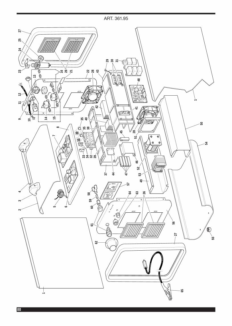
ART. 361.95
1
23
4
5 6
78
1514
2616
10911
1224
23
13
25
21
27
22 28 43
29 30 31
4757
4437
4953
5246
45
5128
4148
42
4038
3933 34 32
3535
50
1
54
55
6160
5958
62
64 63 26
5627
65
81
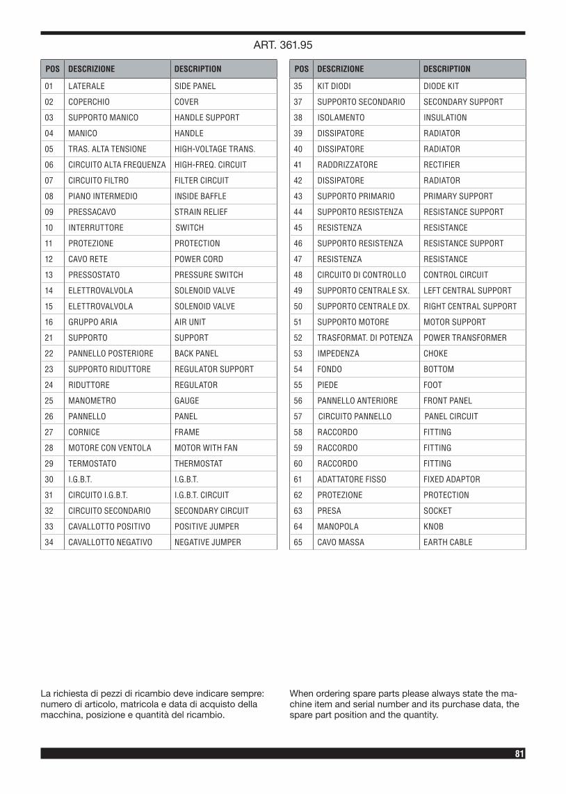
La richiesta di pezzi di ricambio deve indicare sempre: numero di articolo, matricola e data di acquisto della macchina, posizione e quantità del ricambio.
When ordering spare parts please always state the ma-chine item and serial number and its purchase data, the spare part position and the quantity.
POS DESCRIZIONE DESCRIPTION
01 LATERALE SIDE PANEL
02 COPERCHIO COVER
03 SUPPORTO MANICO HANDLE SUPPORT
04 MANICO HANDLE
05 TRAS. ALTA TENSIONE HIGH-VOLTAGE TRANS.
06 CIRCUITO ALTA FREQUENZA HIGH-FREQ. CIRCUIT
07 CIRCUITO FILTRO FILTER CIRCUIT
08 PIANO INTERMEDIO INSIDE BAFFLE
09 PRESSACAVO STRAIN RELIEF
10 INTERRUTTORE SWITCH
11 PROTEZIONE PROTECTION
12 CAVO RETE POWER CORD
13 PRESSOSTATO PRESSURE SWITCH
14 ELETTROVALVOLA SOLENOID VALVE
15 ELETTROVALVOLA SOLENOID VALVE
16 GRUPPO ARIA AIR UNIT
21 SUPPORTO SUPPORT
22 PANNELLO POSTERIORE BACK PANEL
23 SUPPORTO RIDUTTORE REGULATOR SUPPORT
24 RIDUTTORE REGULATOR
25 MANOMETRO GAUGE
26 PANNELLO PANEL
27 CORNICE FRAME
28 MOTORE CON VENTOLA MOTOR WITH FAN
29 TERMOSTATO THERMOSTAT
30 I.G.B.T. I.G.B.T.
31 CIRCUITO I.G.B.T. I.G.B.T. CIRCUIT
32 CIRCUITO SECONDARIO SECONDARY CIRCUIT
33 CAVALLOTTO POSITIVO POSITIVE JUMPER
34 CAVALLOTTO NEGATIVO NEGATIVE JUMPER
POS DESCRIZIONE DESCRIPTION
35 KIT DIODI DIODE KIT
37 SUPPORTO SECONDARIO SECONDARY SUPPORT
38 ISOLAMENTO INSULATION
39 DISSIPATORE RADIATOR
40 DISSIPATORE RADIATOR
41 RADDRIZZATORE RECTIFIER
42 DISSIPATORE RADIATOR
43 SUPPORTO PRIMARIO PRIMARY SUPPORT
44 SUPPORTO RESISTENZA RESISTANCE SUPPORT
45 RESISTENZA RESISTANCE
46 SUPPORTO RESISTENZA RESISTANCE SUPPORT
47 RESISTENZA RESISTANCE
48 CIRCUITO DI CONTROLLO CONTROL CIRCUIT
49 SUPPORTO CENTRALE SX. LEFT CENTRAL SUPPORT
50 SUPPORTO CENTRALE DX. RIGHT CENTRAL SUPPORT
51 SUPPORTO MOTORE MOTOR SUPPORT
52 TRASFORMAT. DI POTENZA POWER TRANSFORMER
53 IMPEDENZA CHOKE
54 FONDO BOTTOM
55 PIEDE FOOT
56 PANNELLO ANTERIORE FRONT PANEL
57 CIRCUITO PANNELLO PANEL CIRCUIT
58 RACCORDO FITTING
59 RACCORDO FITTING
60 RACCORDO FITTING
61 ADATTATORE FISSO FIXED ADAPTOR
62 PROTEZIONE PROTECTION
63 PRESA SOCKET
64 MANOPOLA KNOB
65 CAVO MASSA EARTH CABLE
ART. 361.95
82
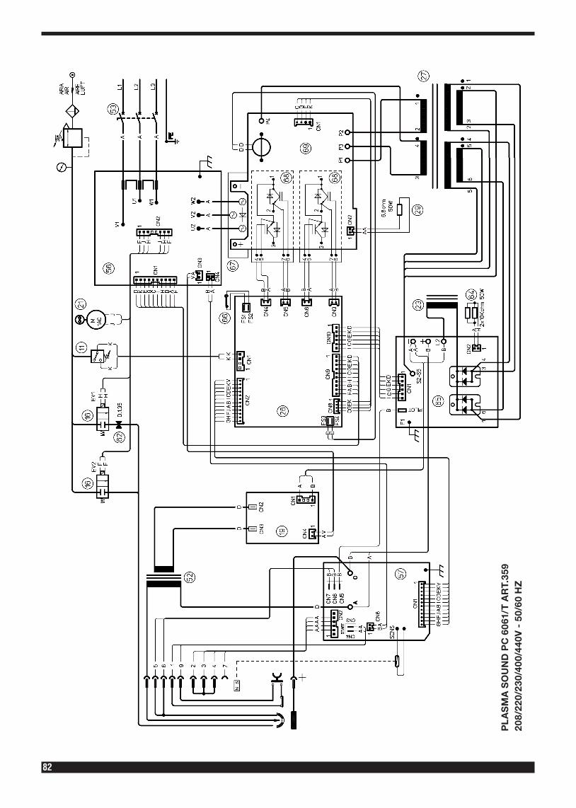
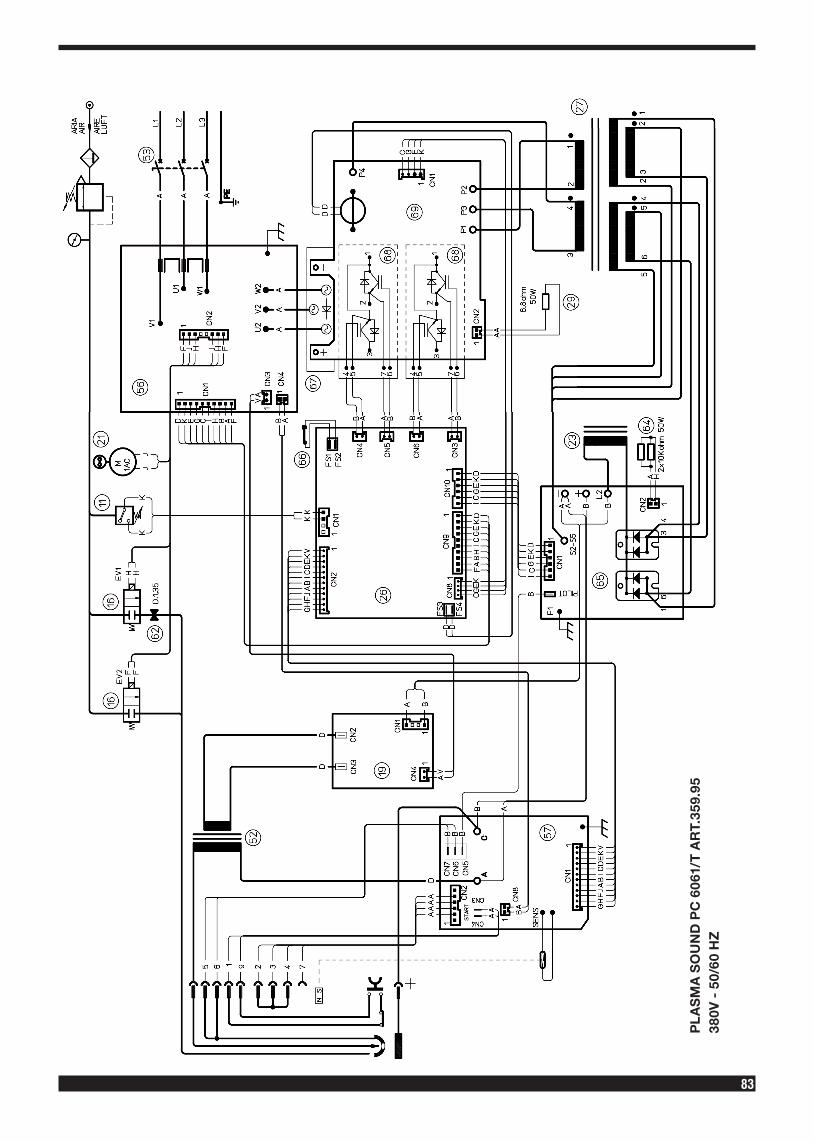
PL
AS
MA
SO
UN
D P
C 6
061/
T A
RT.
359
208/
220/
230/
400/
440V
- 5
0/60
HZ
83
PL
AS
MA
SO
UN
D P
C 6
061/
T A
RT.
359.
9538
0V -
50/
60 H
Z
84
PL
AS
MA
SO
UN
D P
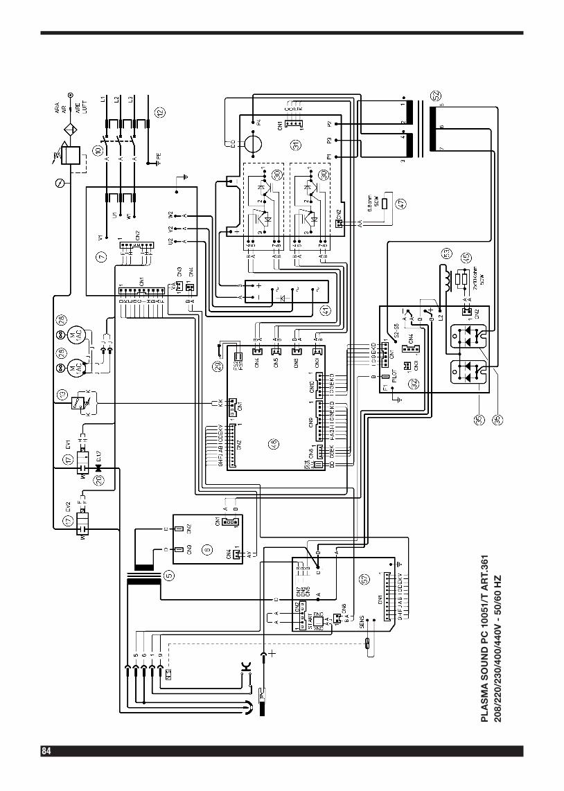
C 1
0051
/T A
RT.
361
208/
220/
230/
400/
440V
- 5
0/60
HZ
85
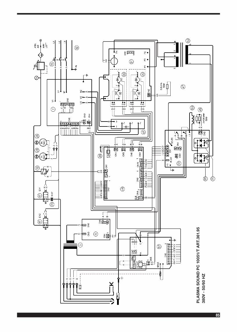
PL
AS
MA
SO
UN
D P
C 1
0051
/T A
RT.
361.
9538
0V -
50/
60 H
Z
86
TABELLE DI TAGLIOCUTTING CHARTS
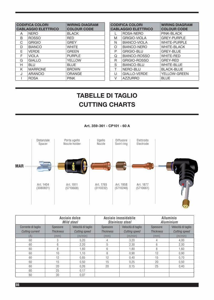
CODIFICA COLORI CABLAGGIO ELETTRICO
WIRING DIAGRAM COLOUR CODE
A NERO BLACKB ROSSO REDC GRIGIO GREYD BIANCO WHITEE VERDE GREENF VIOLA PURPLEG GIALLO YELLOWH BLU BLUEK MARRONE BROWNJ ARANCIO ORANGEI ROSA PINK
CODIFICA COLORI CABLAGGIO ELETTRICO
WIRING DIAGRAM COLOUR CODE
L ROSA-NERO PINK-BLACKM GRIGIO-VIOLA GREY-PURPLEN BIANCO-VIOLA WHITE-PURPLEO BIANCO-NERO WHITE-BLACKP GRIGIO-BLU GREY-BLUEQ BIANCO-ROSSO WHITE-REDR GRIGIO-ROSSO GREY-REDS BIANCO-BLU WHITE-BLUET NERO-BLU BLACK-BLUEU GIALLO-VERDE YELLOW-GREENV AZZURRO BLUE
Art. 359-361 - CP101 - 60 A
Acciaio dolce Mild steel
Acciaio inossidabile Stainless steel
Alluminio Aluminium
Corrente di taglioCutting current
SpessoreThickness
Velocità di taglioCutting speed
SpessoreThickness
Velocità di taglioCutting speed
SpessoreThickness
Velocità di taglioCutting speed
(A) (mm) (m/min) (mm) (m/min) (mm) (m/min)60 3 5,20 4 3,20 4 4,0060 6 2,20 5 2,30 6 2,3060 8 1,60 6 1,80 8 1,6060 10 1,10 8 0,90 12 0,9060 12 0,85 12 0,40 15 0,7060 15 0,50 15 0,25 20 0,5060 20 0,26 20 0,15 25 0,4060 25 0,1760 30 0,07
Art. 1765(3110232)
Art. 1958(5710248)
Art. 1877(5710661)
Art. 1911(5710668)
UgelloNozzle
DiffusoreSwirl ring
ElettrodoElectrode
Porta ugelloNozzle holder
Art. 1404(3080821)
MAR
DistanzialeSpacer
87
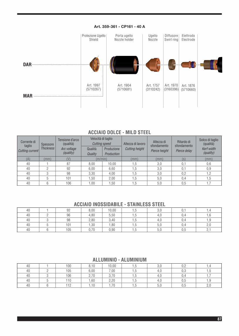
Art. 359-361 - CP161 - 40 A
Art. 1757 (3110242)
Art. 1970 (3160396)
Art. 1876 (5710660)
Art. 1904 (5710681)
UgelloNozzle
DiffusoreSwirl ring
ElettrodoElectrode
Porta ugelloNozzle holder
Protezione UgelloShield
Art. 1997 (5710267)
DAR
MAR
Corrente di taglio
Cutting current
Spessore Thickness
Tensione d’arco (qualità)
Arc voltage (quality)
Velocità di taglioCutting speed Altezza di lavoro
Cutting height
Altezza di sfondamentoPierce height
Ritardo di sfondamentoPierce delay
Solco di taglio (qualità)
Kerf width (quality)
QualitàQuality
ProduzioneProduction
(A) (mm) (V) (m/min) (mm) (mm) (s) (mm)40 1 87 8,00 10,00 1,5 3,0 0,1 0,640 2 92 6,00 6,60 1,5 3,0 0,1 0,940 3 98 3,30 4,00 1,5 3,0 0,2 1,240 5 101 1,50 2,00 1,5 5,0 0,4 1,540 6 106 1,00 1,50 1,5 5,0 0,5 1,7
40 1 92 8,00 10,00 1,5 3,0 0,1 1,440 2 96 4,80 5,50 1,5 4,0 0,4 1,640 3 98 2,80 3,40 1,5 4,0 0,4 1,940 5 101 1,30 1,80 1,5 5,0 0,4 2,040 6 105 0,70 0,90 1,5 5,0 0,5 2,1
40 1 100 8,10 10,00 1,5 3,0 0,2 1,440 2 105 6,00 7,00 1,5 4,0 0,3 1,540 3 106 2,70 3,70 1,5 4,0 0,4 1,740 5 110 1,60 2,20 1,5 4,0 0,5 1,940 6 112 1,10 1,70 1,5 5,0 0,5 2,0
ACCIAIO DOLCE - MILD STEEL
ACCIAIO INOSSIDABILE - STAINLESS STEEL
ALLUMINIO - ALUMINIUM
88
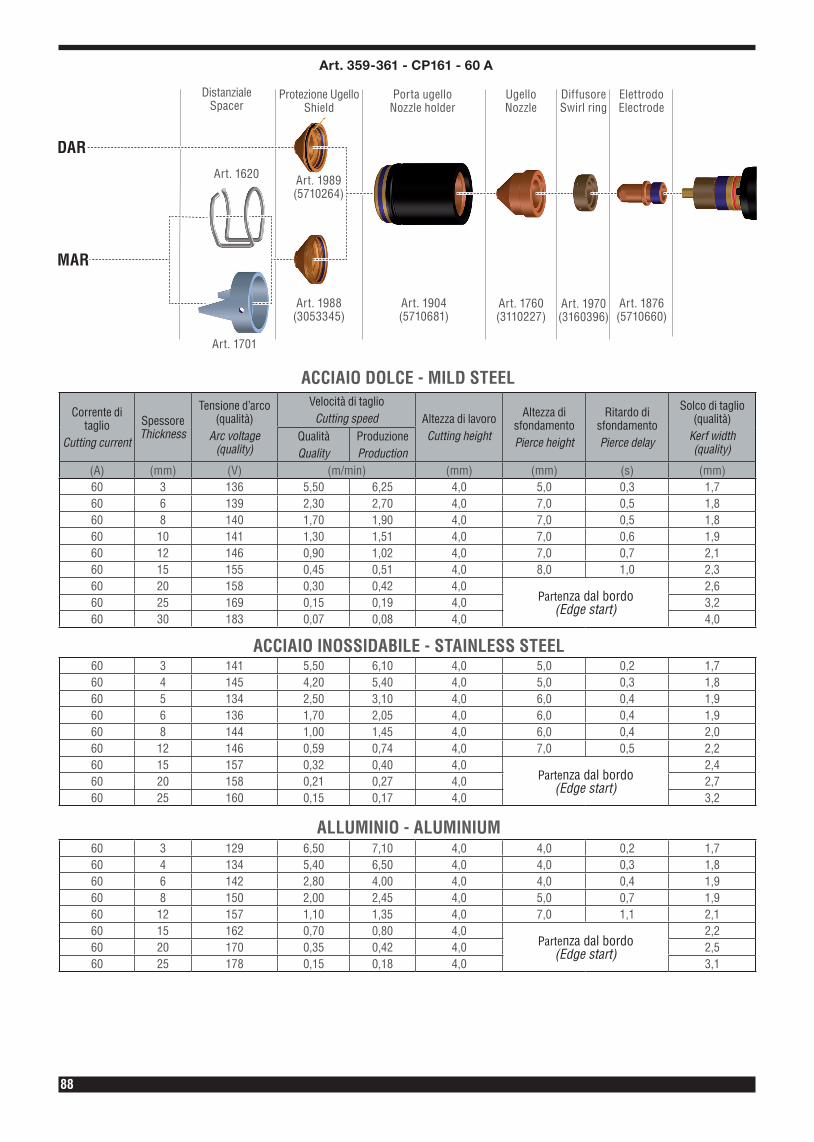
Art. 1760 (3110227)
Art. 1970 (3160396)
Art. 1876 (5710660)
Art. 1904 (5710681)
UgelloNozzle
DiffusoreSwirl ring
ElettrodoElectrode
Porta ugelloNozzle holder
Protezione UgelloShield
Art. 1988 (3053345)
Art. 1620
Art. 1701
Art. 1989 (5710264)
MAR
DAR
DistanzialeSpacer
Art. 359-361 - CP161 - 60 A
Corrente di taglio
Cutting current
Spessore Thickness
Tensione d’arco (qualità)
Arc voltage (quality)
Velocità di taglioCutting speed Altezza di lavoro
Cutting height
Altezza di sfondamentoPierce height
Ritardo di sfondamentoPierce delay
Solco di taglio (qualità)
Kerf width (quality)
QualitàQuality
ProduzioneProduction
(A) (mm) (V) (m/min) (mm) (mm) (s) (mm)60 3 136 5,50 6,25 4,0 5,0 0,3 1,760 6 139 2,30 2,70 4,0 7,0 0,5 1,860 8 140 1,70 1,90 4,0 7,0 0,5 1,860 10 141 1,30 1,51 4,0 7,0 0,6 1,960 12 146 0,90 1,02 4,0 7,0 0,7 2,160 15 155 0,45 0,51 4,0 8,0 1,0 2,360 20 158 0,30 0,42 4,0
Partenza dal bordo(Edge start)
2,660 25 169 0,15 0,19 4,0 3,260 30 183 0,07 0,08 4,0 4,0
60 3 141 5,50 6,10 4,0 5,0 0,2 1,760 4 145 4,20 5,40 4,0 5,0 0,3 1,860 5 134 2,50 3,10 4,0 6,0 0,4 1,960 6 136 1,70 2,05 4,0 6,0 0,4 1,960 8 144 1,00 1,45 4,0 6,0 0,4 2,060 12 146 0,59 0,74 4,0 7,0 0,5 2,260 15 157 0,32 0,40 4,0
Partenza dal bordo(Edge start)
2,460 20 158 0,21 0,27 4,0 2,760 25 160 0,15 0,17 4,0 3,2
60 3 129 6,50 7,10 4,0 4,0 0,2 1,760 4 134 5,40 6,50 4,0 4,0 0,3 1,860 6 142 2,80 4,00 4,0 4,0 0,4 1,960 8 150 2,00 2,45 4,0 5,0 0,7 1,960 12 157 1,10 1,35 4,0 7,0 1,1 2,160 15 162 0,70 0,80 4,0
Partenza dal bordo(Edge start)
2,260 20 170 0,35 0,42 4,0 2,560 25 178 0,15 0,18 4,0 3,1
ACCIAIO DOLCE - MILD STEEL
ACCIAIO INOSSIDABILE - STAINLESS STEEL
ALLUMINIO - ALUMINIUM
89
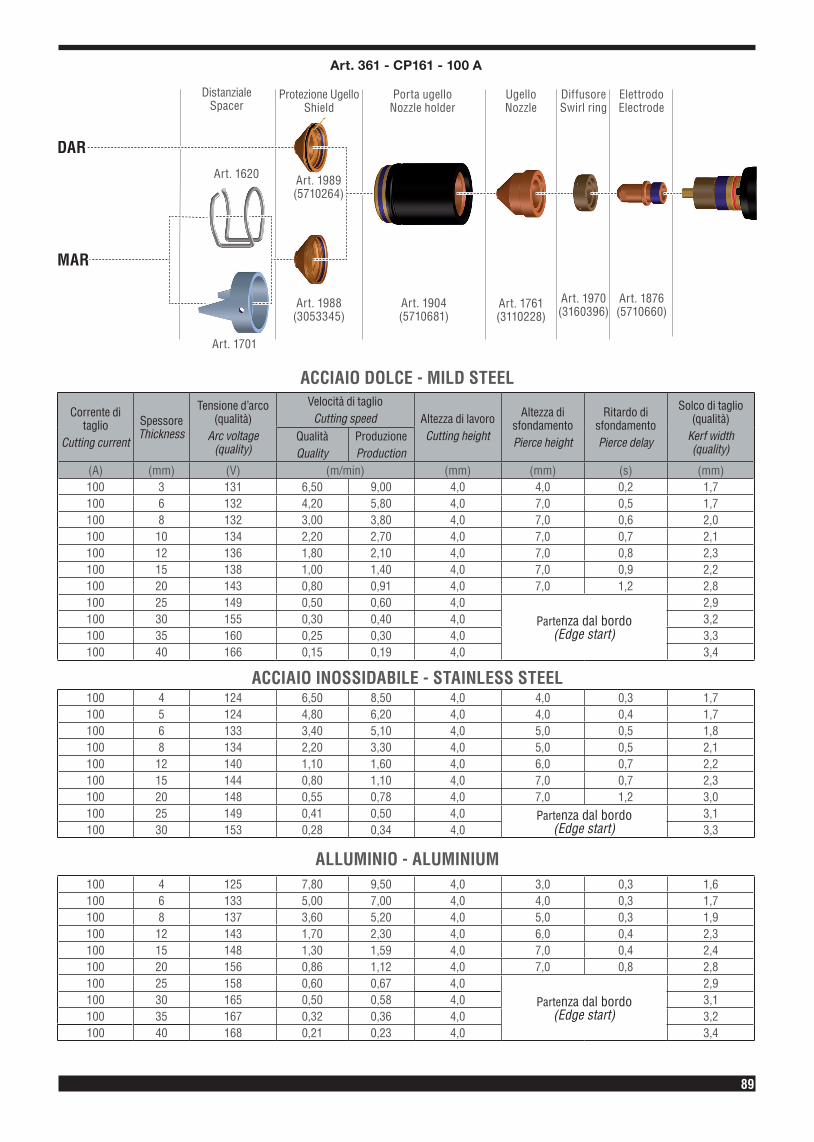
Art. 1761 (3110228)
Art. 1970 (3160396)
Art. 1876 (5710660)
Art. 1904 (5710681)
UgelloNozzle
DiffusoreSwirl ring
ElettrodoElectrode
Porta ugelloNozzle holder
Protezione UgelloShield
Art. 1988 (3053345)
Art. 1620
Art. 1701
Art. 1989 (5710264)
MAR
DAR
DistanzialeSpacer
Art. 361 - CP161 - 100 A
Corrente di taglio
Cutting current
Spessore Thickness
Tensione d’arco (qualità)
Arc voltage (quality)
Velocità di taglioCutting speed Altezza di lavoro
Cutting height
Altezza di sfondamentoPierce height
Ritardo di sfondamentoPierce delay
Solco di taglio (qualità)
Kerf width (quality)
QualitàQuality
ProduzioneProduction
(A) (mm) (V) (m/min) (mm) (mm) (s) (mm)100 3 131 6,50 9,00 4,0 4,0 0,2 1,7100 6 132 4,20 5,80 4,0 7,0 0,5 1,7100 8 132 3,00 3,80 4,0 7,0 0,6 2,0100 10 134 2,20 2,70 4,0 7,0 0,7 2,1100 12 136 1,80 2,10 4,0 7,0 0,8 2,3100 15 138 1,00 1,40 4,0 7,0 0,9 2,2100 20 143 0,80 0,91 4,0 7,0 1,2 2,8100 25 149 0,50 0,60 4,0
Partenza dal bordo(Edge start)
2,9100 30 155 0,30 0,40 4,0 3,2100 35 160 0,25 0,30 4,0 3,3100 40 166 0,15 0,19 4,0 3,4
100 4 124 6,50 8,50 4,0 4,0 0,3 1,7100 5 124 4,80 6,20 4,0 4,0 0,4 1,7100 6 133 3,40 5,10 4,0 5,0 0,5 1,8100 8 134 2,20 3,30 4,0 5,0 0,5 2,1100 12 140 1,10 1,60 4,0 6,0 0,7 2,2100 15 144 0,80 1,10 4,0 7,0 0,7 2,3100 20 148 0,55 0,78 4,0 7,0 1,2 3,0100 25 149 0,41 0,50 4,0 Partenza dal bordo
(Edge start)3,1
100 30 153 0,28 0,34 4,0 3,3
100 4 125 7,80 9,50 4,0 3,0 0,3 1,6100 6 133 5,00 7,00 4,0 4,0 0,3 1,7100 8 137 3,60 5,20 4,0 5,0 0,3 1,9100 12 143 1,70 2,30 4,0 6,0 0,4 2,3100 15 148 1,30 1,59 4,0 7,0 0,4 2,4100 20 156 0,86 1,12 4,0 7,0 0,8 2,8100 25 158 0,60 0,67 4,0
Partenza dal bordo(Edge start)
2,9100 30 165 0,50 0,58 4,0 3,1100 35 167 0,32 0,36 4,0 3,2100 40 168 0,21 0,23 4,0 3,4
ACCIAIO INOSSIDABILE - STAINLESS STEEL
ALLUMINIO - ALUMINIUM
ACCIAIO DOLCE - MILD STEEL

92
CEBORA S.p.A - Via Andrea Costa, 24 - 40057 Cadriano di Granarolo - BOLOGNA - ItalyTel. +39.051.765.000 - Fax. +39.051.765.222
www.cebora.it - e-mail: [email protected]


![Branden Hale- Plasma Cutter[1]](https://img.pdfslide.us/doc/110x75/55cf9871550346d03397aacb/branden-hale-plasma-cutter1.jpg)